COORDINATING RESEARCH COUNCIL, INC. 5755 NORTH POINT PARKWAY ● SUITE 265 ● ALPHARETTA, GA 30022 CRC Report No. AV-26-17 DEVELOPMENT OF INDUSTRY REFERENCE FLUIDS FOR ASTM D3241 TESTING Final Report December 2020
Transcript
COORDINATING RESEARCH COUNCIL, INC.
5755 NORTH POINT PARKWAY ● SUITE 265 ● ALPHARETTA, GA 30022
CRC Report No. AV-26-17
DEVELOPMENT OF INDUSTRY REFERENCE FLUIDS FOR ASTM
D3241 TESTING
Final Report
December 2020
The Coordinating Research Council, Inc. (CRC) is a non-profit
corporation supported by the petroleum and automotive
equipment industries. CRC operates through the committees
made up of technical experts from industry and government
who voluntarily participate. The four main areas of research
within CRC are: air pollution (atmospheric and engineering
studies); aviation fuels, lubricants, and equipment
performance; heavy-duty vehicle fuels, lubricants, and
equipment performance (e.g., diesel trucks); and light-duty
vehicle fuels, lubricants, and equipment performance (e.g.,
passenger cars). CRC’s function is to provide the mechanism
for joint research conducted by the two industries that will
help in determining the optimum combination of petroleum
products and automotive equipment. CRC’s work is limited to
research that is mutually beneficial to the two industries
involved. The final results of the research conducted by, or
under the auspices of, CRC are available to the public.
LEGAL NOTICE
This report was prepared by CONTRACTOR as an account of
work sponsored by the Coordinating Research Council (CRC).
Neither the CRC, members of the CRC, CONTRACTOR, nor
any person acting on their behalf: (1) makes any warranty,
express or implied, with respect to the use of any information,
apparatus, method, or process disclosed in this report, or (2)
assumes any liabilities with respect to use of, inability to use, or
damages resulting from the use or inability to use, any
information, apparatus, method, or process disclosed in this
report. In formulating and approving reports, the appropriate
committee of the Coordinating Research Council, Inc. has not
investigated or considered patents which may apply to the
subject matter. Prospective users of the report are responsible
for protecting themselves against liability for infringement of
patents.
Fuels & Combustion Division | Fuel Science Group
300 College Park, Dayton OH 45469-8211 | udri.udayton.edu
UDR-TR-2020-81
Development of Industry Reference Fluids for ASTM D3241 Testing Submitted to: Coordinating Research Council, Inc. 5755 North Point Parkway, Suite 265 Alpharetta, GA 30022 Submitted by: Z. J. West, S. S. Mueller, S. Zabarnick University of Dayton Research Institute
December 2020
LEGAL NOTICE
This report was prepared by the University of Dayton Research Institute (UDRI) as an account of work by the Coordinating Research Council (CRC). Neither the CRC, members of the CRC, UDRI nor any person acting on their behalf: (1) makes any warranty, express or implied, with respect to the use of any information, apparatus, method, or process disclosed in this report, or (2) assumes any liabilities with respect to use of, inability to use, or damages resulting from the use or inability to use, any information, apparatus, method, or process disclosed in this report.
2
EXECUTIVE SUMMARY Assurance of aviation turbine fuel thermal stability is a necessary check for today’s modern aircraft. While many methods exist to examine jet fuel thermal stability, the only allowed method for assessing jet fuel thermal stability—for most internationally recognized jet fuel specifications—is ASTM D3241. A confluence of recent events, such as: introduction of metrological methods of heater tube rating, reported variations between D3241 instrument versions, and observed variability of D3241 results during the ASTM Interlaboratory Crosscheck Program, has given rise to a desire for a means of verifying the test equipment used for thermal stability evaluation. In an effort to improve thermal stability evaluations, we report on the development of a robust and consistent thermal stability reference fluid. The candidate fluid contains organo-nitrogen and organo-sulfur species to closely replicate actual jet fuel thermal instability issues often encountered in commercial fuels. It was found that the chemical formulation (both the choice of instigating chemical species and the concentration of the species), as well as the ASTM D3241 operating temperature strongly influence the magnitude and location of surface deposition on heater tube specimens and the magnitude of system pressure drop. Accelerated storage stability results indicate a candidate reference fluid could be shelf stable for at least 12 months. Preliminary interlaboratory (pre-ILS) results are provided for both a high depositing and low depositing fluid. The pre-ILS results indicate excellent agreement for pass/fail surface deposit results, however, absolute deposit values vary.
Appendix A: Pre-ILS Participant Instructions and Results Template ............................................. 37
Appendix B: Draft Safety Data Sheet (SDS) ................................................................................... 39
4
INTRODUCTION Thermal stability of aviation turbine fuel—that is, the propensity of a fuel to produce nuisance carbonaceous deposits due to oxidative pathways at elevated temperatures—is an important performance property. The long approved quality assurance/quality control (QA/QC) method for assessing the thermal stability of aviation turbine fuels has been ASTM D3241 (and the technically equivalent IP 323). It is known that the precision of D3241 deposition ratings, as evaluated using the visual rating method or VTR (Annex A1), have the highest uncertainty around the most common pass/fail specification point, i.e., less than 3 color code [ASTM International, 1993]. Additionally, recent results from an ASTM Crosscheck Study have shown that metrological methods of heater tube evaluation, i.e., ellipsometric tube rating (ETR, Annex A3) and interferometric tube rating (ITR, Annex A2), also show high uncertainty for a fuel at or near “failing” status [Bower, 2016; Bower, 2019]. That is to say that D3241 has the lowest uncertainty, i.e., highest confidence, for assessing fuels of very “high” and very “low” stability, but the opposite is true for assessing fuels that are of “marginal” stability where D3241 has high uncertainty, i.e., low confidence. While these observations may give industry participants pause about the interpretation of D3241 results, especially for marginal fuels, the longevity and pervasiveness of the method itself means it would be difficult to transition to a completely different method of thermal stability assessment. It is therefore important to assess the precision of not only current instrumentation and consumables, but also future iterations of the apparatus itself. Observations of D3241 repeatability and reproducibility have always been made using real aviation turbine fuels, which are in either limited or finite quantity and so means they cannot be reproduced over long periods of time. Real commercial fuels tend to be poorly characterized with respect to their trace composition and the thermal stability performance of real fuels can change over time due to storage and handling conditions. Fuel trace composition is known to be a significant cause of thermal instability in fuels [Hazlett, 1991; Zabarnick et al., 2019], however, the exact chemical composition of poor fuels is variable and often difficult to monitor without highly sophisticated research analysis techniques [Kuprowicz et al., 2007]. There is no consistent thermal stability reference fluid that is both well characterized and reproducible over long periods of time. Therefore, it is difficult to identify specific instrumentation factors that might contribute to high method uncertainty. With these concepts in mind, the Coordinating Research Council (CRC) initiated a program to develop one or more thermal stability reference fluid(s) for use with ASTM D3241 and/or IP 323. The initial program objectives were twofold: 1) develop a reference fluid that produces a consistent surface deposit on D3241 heater tube specimen, and 2) develop a reference fluid that produces a consistent D3241 pressure
5
differential response. Both objectives were to be met using chemistry that proceeds via known thermal-oxidative pathways, in an effort to more closely represent fouling experienced by real fuel samples. It was originally specified that the D3241 testing
should be conducted between 250 to 300C (preferably at either 260 or 275C) and that the pressure differential should reach 100 mmHg within 60 to 90 minutes of test duration under similar temperature conditions. A single fluid to achieve both tasks was desirable, however, multiple reference fluids could also be used. After starting the program and reporting of initial results, the CRC project panel (i.e., the industry panel overseeing this work) relaxed the pressure differential requirements, and emphasized
the use of the preferred temperatures, i.e., 260 or 275C, for the surface deposit reference fluid. However, based on recent thermal stability issues reported in the field, a reference fluid for differential pressure remains a valid interest. Additionally, it was never the intent of this project to produce a finished test fluid, but rather to provide a test fluid that would then be subjected to interlaboratory study (ILS) procedures before being added to ASTM D3241 or IP 323. We present our findings on the development of such reference fluids herein.
6
EXPERIMENTAL Reference fluid candidates were subjected to thermal stress according to the ASTM D3241 method using a single ALCOR Mark III JFTOT® apparatus. Heater tube specimen were generated using clean (new) standard aluminum Falex heater tubes (P/N: 400-560-001) in accord with ASTM D3241. The heater tube specimens were evaluated after testing using both a Falex Model 430 ellipsometer and an AD Systems DR10 interferometer according to D3241 Annex 3 and Annex 2, respectively. Table 1 lists the chemicals used as instability instigating compounds in this study. All chemicals were 98% pure (or greater) and were procured from Sigma-Aldrich; chemicals were used as received from the manufacturer. Table 2 lists the products used as base solvent; base solvents were used as received from the manufacturer unless otherwise specified. Mixtures of N and S compounds, in an aliphatic solvent, were hand prepared in small batches. All N and S compounds were readily dissolvable at ambient conditions with the exception of phenyl disulfide (PhS2Ph) which was a solid that required about 5 minutes of mixing in an ultrasonic bath to dissolve.
Table 1. List of Instigating Compounds Compound Name
Exxsol™ D80 Fluid n/a ExxonMobil Chemical Co. Exxsol™ D110 Fluid n/a ExxonMobil Chemical Co.
Deodorized 175 Solvent VS-DEO175 Rock Valley Oil & Chemical ShellSol™ D80 Q7722 Shell Chemical LP
LPA®-170 Solvent n/a Sasol Chemicals LLC
Accelerated Storage Testing Accelerated aging of selected solvents/samples at 43°C over a period of 12 weeks was performed in an effort to simulate long-term (i.e., 12 month) ambient storage. Candidate solvents were stored either with or without deposit instigating additives, and either in the presence or absence of oxygen (i.e., air). For solvent stored without N & S compounds, the instigating chemicals were added after storage, just prior to D3241
7
testing. Samples stored in the absence of oxygen were nitrogen sparged for about 15 minutes (at a gentle rate) to displace oxygen (dissolved and in the container ullage) prior to sealing the one gallon, epoxy lined metal container. No active gas sparging was performed on samples stored air saturated since it was assumed that normal handling of the samples (e.g., pouring/transferring between containers) provided sufficient air saturation. Samples were tested according to ASTM D3241 prior to aging and after both 6 and 12 weeks of accelerated aging. Control samples of each fluid were stored at ambient laboratory conditions throughout the 12-week period and were tested at coincident time intervals as the aged samples. Table 3 shows the number of replicate samples run for each test condition; data were collected on a total of 36 D3241 runs.
Table 3. Accelerated Aging Test Matrix, Number of Replicate Samples per Storage Treatment
RESULTS AND DISCUSSION Previous research has shown that combinations of S, N, and O containing heteroatomic species (dissolved in either fuel or solvent) can cause thermal-oxidative deposition at 140°C in a quartz crystal microbalance (QCM) apparatus (ASTM D7739) in a matter of hours [Zabarnick et al., 2017]. Additional studies have demonstrated that these S, N, and O heteroatomic species, in combination, can cause deposition using a D3241 apparatus, even though temperatures and residence times are considerably different in D3241 than those of D7739, e.g., fuel experiences non-isothermal conditions in D3241 with a maximum wetted wall temperature of typically 235−325°C and residence times of seconds [Zabarnick et al., 2019]. In addition to sulfur and nitrogen containing compounds, the original request for proposal from the CRC suggested other potential deposit instigating components for exploration such as: nitrate type Cetane improver, low molecular weight polyisobutylene succinimides (PIBSI) [Reid & Barker, 2013], zinc neodecanoate [Lacey et al., 2016], and 2-methylindole and/or copper [Taylor, 2002]. However, our decision to pursue S, N, and O as instigating compounds is due to our extensive research on real aviation turbine fuels [Kuprowicz et al., 2007; Zabarnick et al., 2016; Zabarnick et al., 2017; Zabarnick et al., 2019]. We believe these heteroatomic compounds are the frequent cause of thermal instabilities in jet fuel and thus represent realistic pathways to deposit during D3241 testing.
Preliminary Studies One challenge with this program is the very large parameter space that can be explored to achieve the desired outcome. Based on our past experiences, we chose to limit the number of organo-nitrogen and organo-sulfur containing compounds to a few each, while exploring other factors such as set point temperature (that is the maximum wetted wall temperature), species combinations, and instigating material concentration. Figure 1 shows some of the preliminary work investigating instigating species mixtures. This figure shows deposition profiles, i.e., circumferentially averaged ETR deposit thickness versus axial length along a heater tube specimen, for the neat solvent (Exxsol D80) and four different mixture combinations of possible instigating compounds. The neat solvent presents no measurable deposit, however, with the addition of appropriate N and S compounds significant levels of deposition are formed between about 35 to 55 mm along the tube. As reported elsewhere, the maximum heater tube wetted wall temperature occurs between about 30 to 40 mm with sharp declines in temperature as the heater tube entrance and exit points are approached [Sander et al., 2015]. The nature of the heater tube wall temperature is due to the cooled bus bars (near the entrance and exit) along with the resistive heating of the aluminum heater tube. The drastic rise in surface deposits seen on these tube specimens (Figure 1) appears connected to the maximum wetted wall temperature. Additionally, dissolved oxygen
9
concentrations, both before and after the heater tube section, were monitored for some of the initial candidate reference fluids using an InPro 6850i polarogaphic oxygen sensor (Mettler-Toledo, LLC, Columbus, OH). The resulting changes in the dissolved oxygen showed complete oxygen consumption for the cases measured (data not shown), thus the measurements were discontinued for subsequent trials. These observations combined, i.e., oxygen consumption and temperature sensitivity, demonstrate that the observed surface and bulk deposition products are due to known thermal-oxidative chemical pathways.
Figure 1. D3241 heater tube profiles, via ETR, of average circumferential deposit thickness with various mixtures of N and S compounds in Exxsol D80 at either 275 or 280°C; all N and S compounds added at 200 mg/L each (nominal). Having established that deposits could be produced using an aliphatic solvent with a few compounds added at low levels, a study was conducted to vary the concentration of the instigating compounds for the following two mixture blends: 1) HA + Ph2S2, and 2) DMA
+ HS. The resulting D3241 data, taken with a set point temperature of 300C, are listed in Table 4. As the table shows, the deposit max spot thickness increases as concentration increases for both mixture sets. And while the DMA + HS mixture shows
no P at either concentration, the HA + Ph2S2 mixture gives a moderate amount of P,
6.5 mmHg, at the lower concentration and a maximum amount of P, 280 mmHg, at the higher concentration tested. These results demonstrate that the choice of instigating compounds in the mixture influence both the surface deposition and pressure drop
Fuel Flow
10
magnitude. Additionally, the concentration of a given mixture seems to influence deposition in a proportional manner.
Table 4. D3241 Results for Mixtures of Exxsol D80 and Various Compounds at 300C
Species Concentrations (mg/L) ETR Max Spot (nm)
Max P (mmHg) HA DMA Ph2S2 HS
100 - 100 - 107 6.5
200 - 200 - 157 280
- 200 - 200 40 0
- 300 - 300 77 0
It is clear that low levels of organo-nitrogen and organo-sulfur containing compounds can be combined to produce both surface deposits and pressure drop in D3241 studies, with the amounts and profiles of products being concentration and mixture specific. It was also of interest to explore what effect set point temperature had on the method results. Figure 2 shows replicate runs of a mixture of Exxsol D80 with HA 200 mg/L and Ph2S2 200 mg/L as a function of temperature. As this figure shows, the onset of deposition within the tube shifts further upstream as the set point temperature increases. This makes intuitive sense as reaction rates accelerate significantly with temperature thus forcing oxidation and deposition reactions to occur earlier within the heated portion of the tube. Similarly, Figure 3 shows pressure drop profiles for the same
set of replicate runs with respect to temperature. As these data show, the 300C runs
produce a maximum level of P, 280 mmHg, between about 90 to 100 minutes within the run, thereby initiating the filter by-pass. This level, and rate, of pressure drop
satisfies the original P target (shown on Figure 3 with red box); however, this target P could not be attained at lower operating temperatures. Significantly less pressure drop
is exhibited at 275C and even less still at 260C. These data indicate that meeting the
originally prescribed differential pressure objective is possible when operating at 300C with 200 mg/L each of HA and Ph2S2. Table 5 lists the max spot thickness and max pressure drop for each of the replicates shown in Figure 2 and Figure 3 along with average values. As these data show, higher
variability was observed for both surface deposits and P values from the 275C set
point experiments opposed to the 260 and 300C runs. It is possible that deposits
produced at 275C caused ETR detector saturation (around 180 to 220 nm), thus
increasing variability in the data. It stands to reason that at 300C the temperature is sufficiently great to force the chemistry to take place—to completion—in a narrow window of time and space along the heater tube, thus providing repeatable deposition profiles (see Figure 2). A similar explanation applies to bulk insoluble product formation at the higher temperature for the chemistry used in these experiments, therefore
11
leading to repeatable P observations at 300C. In contrast, experiments conducted at
260C might be sufficiently low in temperature for the chemical kinetic rates to produce an incipient—or near incipient—level of deposit within the allowed residence time of the D3241 apparatus. This is demonstrated by examination of the deposition profiles in Figure 2, whereby deposits are forming very near the end of the heater tube. As is the case for all of the temperature runs shown, the onset of deposit appears to be relatively consistent with this chemistry.
Figure 2. Profiles of average circumferential deposit along D3241 heater tubes with respect to set point temperature for mixtures of Exxsol D80 with HA 200 mg/L and Ph2S2 200 mg/L; orange/brown-circle
markers are at 300°C (n=3), blue-triangle markers are at 275C (n=5), and grey/black-square markers are
at 260C (n=3).
Table 5. Maximum D3241 Values for a Mixture of Exxsol D80 with HA 200 mg/L and Ph2S2 200 mg/L
T (°C) ETR Max Spot Thickness
(nm) per Replicate Avg Std Dev
1 2 3 4 5
260 141 144 132 139 7
275 154 150 208 216 153 176 33
300 157 160 161 159 2
T (°C)
Max Pressure Drop (mmHg) per Replicate Avg
Std Dev
1 2 3 4 5
260 1 3 3 2 1
275 68 14 39 34 17 34 22
300 280 280 280 280 0
Fuel Flow
12
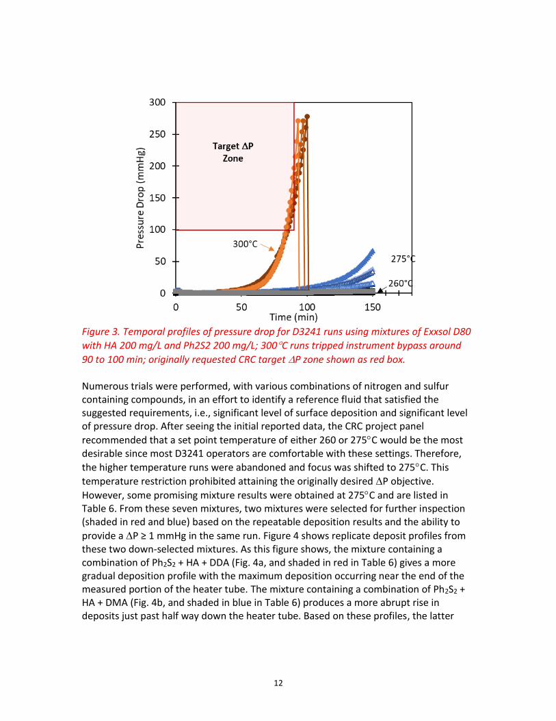
Figure 3. Temporal profiles of pressure drop for D3241 runs using mixtures of Exxsol D80
with HA 200 mg/L and Ph2S2 200 mg/L; 300C runs tripped instrument bypass around
90 to 100 min; originally requested CRC target P zone shown as red box. Numerous trials were performed, with various combinations of nitrogen and sulfur containing compounds, in an effort to identify a reference fluid that satisfied the suggested requirements, i.e., significant level of surface deposition and significant level of pressure drop. After seeing the initial reported data, the CRC project panel
recommended that a set point temperature of either 260 or 275C would be the most desirable since most D3241 operators are comfortable with these settings. Therefore,
the higher temperature runs were abandoned and focus was shifted to 275C. This
temperature restriction prohibited attaining the originally desired P objective.
However, some promising mixture results were obtained at 275C and are listed in Table 6. From these seven mixtures, two mixtures were selected for further inspection (shaded in red and blue) based on the repeatable deposition results and the ability to
provide a P ≥ 1 mmHg in the same run. Figure 4 shows replicate deposit profiles from these two down-selected mixtures. As this figure shows, the mixture containing a combination of Ph2S2 + HA + DDA (Fig. 4a, and shaded in red in Table 6) gives a more gradual deposition profile with the maximum deposition occurring near the end of the measured portion of the heater tube. The mixture containing a combination of Ph2S2 + HA + DMA (Fig. 4b, and shaded in blue in Table 6) produces a more abrupt rise in deposits just past half way down the heater tube. Based on these profiles, the latter
13
combination (shown in Fig. 4b) appears to be more favorable as a reference fluid and thus was advanced as the primary candidate fluid for additional robustness testing.
Figure 4. D3241 heater tube profiles at 275C of Exxsol D80 with a) Ph2S2 150 mg/L + HA 50 mg/L + DDA 100 mg/L or b) Ph2S2 150 mg/L + HA 100 mg/L + DMA 100 mg/L.
a) b)
14
Table 6. Deposit Thickness and Max Pressure Drop Results for Select Samples at 275°C via D3241 (Shaded Rows Are Recommended Formulations)
Nominal Concentrations (mg/L)
ETR Max Spot Thickness (nm)
Max DP (mmHg)
Ph2S2 HA DDA DMA Value Avg Value Avg
100
100
122
132 23
0.6
0.8 0.5
103 1.8
- - 124 0.5
153 0.7
158 0.6
- 100 - 41
42 2 -
0.0 n/a 44 -
150
150 191
191 0 3.9
41 53 191 78.7
100 -
137
131 9
7.1
11 11
141 5.2
50 122 31.1
123 7.9
135 4.5
200
200
154
173 27
68.0
33 18
150 14.4
208 38.6
- - 216 33.9
153 17.0
174 37.1
159 20.4
200
90
83 15
0.3
0.2 0.2 - - 93 0.3
66 -
100
100
145
150 10
33.8
31 38
159 13.7
- 134 23.3
152 105.5
161 1.5
153 8.2
Note: mixture shaded in blue is referred to as “Fluid A” later in this report.
15
Fluid Parameter Studies Assessment of the “ruggedness and sensitivity” of parameters that might impact reference fluid results will now be addressed. The critical parameters of material/chemical sourcing and storage/handling are outlined in the following sub-sections.
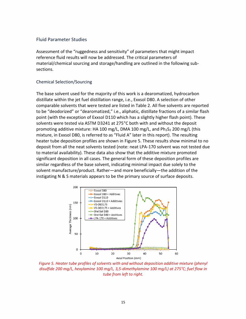
Chemical Selection/Sourcing The base solvent used for the majority of this work is a dearomatized, hydrocarbon distillate within the jet fuel distillation range, i.e., Exxsol D80. A selection of other comparable solvents that were tested are listed in Table 2. All five solvents are reported to be “deodorized” or “dearomatized,” i.e., aliphatic, distillate fractions of a similar flash point (with the exception of Exxsol D110 which has a slightly higher flash point). These solvents were tested via ASTM D3241 at 275°C both with and without the deposit promoting additive mixture: HA 100 mg/L, DMA 100 mg/L, and Ph2S2 200 mg/L (this mixture, in Exxsol D80, is referred to as “Fluid A” later in this report). The resulting heater tube deposition profiles are shown in Figure 5. These results show minimal to no deposit from all the neat solvents tested (note: neat LPA-170 solvent was not tested due to material availability). These data also show that the additive mixture promoted significant deposition in all cases. The general form of these deposition profiles are similar regardless of the base solvent, indicating minimal impact due solely to the solvent manufacture/product. Rather—and more beneficially—the addition of the instigating N & S materials appears to be the primary source of surface deposits.
Figure 5. Heater tube profiles of solvents with and without deposition additive mixture (phenyl disulfide 200 mg/L, hexylamine 100 mg/L, 3,5-dimethylamine 100 mg/L) at 275°C; fuel flow in
tube from left to right.
16
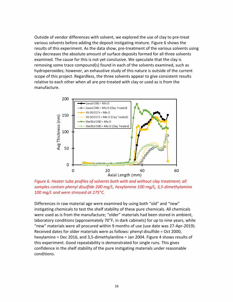
Outside of vendor differences with solvent, we explored the use of clay to pre-treat various solvents before adding the deposit instigating mixture. Figure 6 shows the results of this experiment. As the data show, pre-treatment of the various solvents using clay decreases the absolute amount of surface deposits formed for all three solvents examined. The cause for this is not yet conclusive. We speculate that the clay is removing some trace compound(s) found in each of the solvents examined, such as hydroperoxides; however, an exhaustive study of this nature is outside of the current scope of this project. Regardless, the three solvents appear to give consistent results relative to each other when all are pre-treated with clay or used as is from the manufacture.
Figure 6. Heater tube profiles of solvents both with and without clay treatment; all samples contain phenyl disulfide 200 mg/L, hexylamine 100 mg/L, 3,5-dimethylamine 100 mg/L and were stressed at 275°C. Differences in raw material age were examined by using both “old” and “new” instigating chemicals to test the shelf stability of these pure chemicals. All chemicals were used as is from the manufacture; “older” materials had been stored in ambient, laboratory conditions (approximately 70°F, in dark cabinets) for up to nine years, while “new” materials were all procured within 9 months of use (use date was 27-Apr-2019). Received dates for older materials were as follows: phenyl disulfide = Oct 2000, hexylamine = Dec 2016, and 3,5-dimethylaniline = Jan 2004. Figure 4 shows results of this experiment. Good repeatability is demonstrated for single runs. This gives confidence in the shelf stability of the pure instigating materials under reasonable conditions.
17
Figure 7. Heater tube profiles using “old” and “new” lots of heteroatomic materials; all samples contain phenyl disulfide 200 mg/L, hexylamine 100 mg/L, 3,5-dimethylamine 100 mg/L and were stressed at 275°C.
Accelerated Aging Study Additional “ruggedness” testing involved the accelerated aging of solvents at 43°C over a period of 12 weeks. Candidate solvents were stored both with and without deposit instigating additives, and in the presence and absence of oxygen. For solvent stored without N & S chemicals, the instigating mixture was added after storage, just prior to D3241 testing. Samples stored in the absence of oxygen were nitrogen sparged for about 15 minutes (at a gentle rate) prior to sealing the one-gallon container. Table 3 shows the number of replicate samples run for each test condition; data were collected on a total of 36 runs. The three ambient temperature replicates, for each sample and headspace condition, were run over the course of 12 weeks, while the accelerated aging samples were run in triplicate shortly upon completion of being aged. Average deposit profiles (with error bars depicting one standard deviation) for these data are shown in Figure 8 through Figure 10. Figure 8 shows average deposition profiles for the four different sample preparations in the accelerated aging study stored at ambient temperature (control samples). Ultimately, each sample contains the same concentration of instigating compounds upon test, i.e., Exxsol D80 with Ph2S2 200 mg/L, HA 100 mg/L, and DMA 100 mg/L, and the difference is in when the instigating compounds are added and whether or not the mixture is stored in the presence of oxygen. As these data show, there is excellent agreement in deposition profiles regardless of sample preparation treatment, and
18
relatively low variance within the data over the course of 12 weeks. These results are not surprising considering the prior data collected on this mixture and maintains confidence in our ability to replicate results under well controlled conditions over time.
Figure 8. Average deposit profiles (conducted over a 12-week period) of reference Fluid A (see Table 6) stored at ambient temperature; error bars show one standard deviation with n=3. Figure 9 shows average (n=3) deposit profiles of samples after 12 weeks of accelerated storage at 43°C. These elevated temperature conditions are designed to simulate storage over the course of approximately 12 months under typical ambient conditions. These data show that deposition profiles are qualitatively similar regardless of the sample treatment, and that deposit values are within the given uncertainty of the test. Finally, Figure 10 shows the progression of a single sample treatment, i.e., stored with instigating compounds in the presence of air, over the full 12 week period. This treatment is considered to be the most severe as the instigating materials could be susceptible to oxidation reactions during storage that could change the response of the compounds when tested using D3241. However, like the results shown in Figure 8 and Figure 9, the data shown in Figure 10 demonstrate there is excellent agreement of deposition profiles over the full 12 weeks of aging. These data increase our confidence that the candidate reference fluid, with instigating material, is reasonably “shelf stable.” That is to say, we observe no evidence of degradation in performance, even under accelerated storage conditions.
19
Figure 9. Average deposit profiles of reference Fluid A (see Table 6) after 12 weeks of storage at 43°C; error bars show one standard deviation.
Figure 10. Average deposit profiles of reference Fluid A (see Table 6) samples after 0, 6, and 12 weeks of accelerated storage at 43°C.
20
Repeatability Assessment The previous section demonstrates that the sample treatment, e.g., storage condition, seems to be an insignificant factor on the resulting deposition profile of candidate reference Fluid A. Therefore, if we consider all 36 of these runs as replicates we can start to develop a more robust assessment of variability and uncertainty for this test fluid (on a single instrument). Table 7 lists average values, standard deviations, and ranges for both the max spot thickness and pressure difference measurements for these replicate runs, while Figure 11 shows histograms of the same data set to aid with visualization of the recorded value distribution. These data indicate a relative standard deviation of about 14% for max spot thickness and about 91% for the pressure difference. Although the pressure difference data values give significant variability, most values measure between about 2 to 17 mmHg. That is, in every case a pressure drop of at least 2 mmHg was recorded.
Table 7. Results of n=36 Observations for Exxsol D80 with Ph2S2 200 mg/L, HA 100 mg/L, and DMA 100
mg/L at 275C
Max Spot
Thickness (nm) P
(mmHg) Mean 168 11
Standard Deviation 23 10 Max 219 58 Min 136 2
Figure 11. Histograms of max deposit thickness and pressure difference measured for n=36 observations of
Exxsol D80 with Ph2S2 200 mg/L, HA 100 mg/L, and DMA 100 mg/L at 275C.
21
Reproducibility Assessment A preliminary interlaboratory (pre-ILS) study was conducted to assess the reproducibility of the candidate fluid(s). Nine laboratories, in addition to our own laboratory, agreed to participate and provide anonymized data. The instructions sent to participant laboratories can be found in Appendix A. Based on feedback from the CRC project panel, and the broader fuels community partners, it seemed desirable to further formulate a reference fluid that produced a measurable amount of deposit, but was still of ‘passing’ level, i.e., having a max spot thickness between about 30 to 85 nm. Therefore, UDRI distributed two separate reference fluids to the various laboratories (see Table 8 for fluid formulations); Fluid A is the same formulation reported in the preceding Fluid Parameter Studies and Repeatability Assessment sections and is highlighted in blue in Table 6 (representing a high concentration and corresponding high depositing fluid), while Fluid B contains the same instigating compounds as Fluid A but in lower concentrations (with corresponding lower deposition). Fluid A and Fluid B were both generated gravimetrically in single batch quantities of 36.8 kg and 29.6 kg, respectively; concentrations reported in Table 8 were calculated based on a solvent density of 0.8006 kg/L and took into account compound purity. The Ph2S2, HA, and DMA were weighed and dissolved in a small (ca. 100 mL) amount of Exxsol D80 prior to combining in a clean, epoxy-lined drum; solvent was metered to the total mass, then the entire drum was vigorously blended. Aliquots of each batch were metered into commercially available UN rated, aluminum sample containers approved for jet fuel transportation; volumes shipped to individual laboratories varied based on the number of tests each participant agreed to perform.
Table 8. Single Batch Reference Fluid Formulations Used for Distribution
Fluid A Purity Measured Mass (g)
PPM (mg/kg)
Concentration (mg/L)
Ph2S2 99% 9.2930 250. 200.
HA 99% 4.6467 125. 100.
DMA 98% 4.6936 125. 100.
Total Massa 36,800
Fluid B Purity Measured Mass (g)
PPM (mg/kg)
Concentration (mg/L)
Ph2S2 99% 7.4756 250. 200.
HA 99% 0.7477 25.0 20.0
DMA 98% 0.7561 25.0 20.0
Total Massa 29,600 aTotal mass includes mass of instigating compounds and Exxsol D80 solvent.
22
A variety of test equipment was used during this phase of the study. Variables included both D3241 test apparatus (manufacturer and model) as well as heater tube manufacturer; the number of test setups for each combination of variables is listed in Table 9. Participating laboratories were asked to perform testing in triplicate for each test setup they offered to conduct; therefore, a total of 63 heater tubes were generated using test Fluid A and 44 heater tubes were generated using Fluid B. Two of the Fluid A
experiments were conducted at 260C rather than 275C, which provided interesting data points for comparison, however, those two samples will be treated as outliers and will not be reported with the aggregate data set (therefore reducing the total number of Fluid A heater tube samples to 61). Another complicating factor with this study is the reliance upon the participant’s method for heater tube rating. All laboratories rated tubes visually (VTR), but use of metrology methods varied. Since we requested heater tube specimens be return shipped to UDRI, we were able to rate the heater tubes using our own ETR and/or ITR device. When a laboratory reported responses for ITR, ETR, and multi-wavelength ellipsometric tube rating (MWETR) they were always used/reported. However, in cases when a laboratory was unable to report ETR or ITR data, UDRI tube ratings were reported to supplement the data accordingly (these supplemental data are reported in red typeset in Table 12 and Table 13).
Table 9. Number of Test Setups Based on Fluid Type, Tube Manufacture, and Instrument Manufacture
Fluid A Fluid B
Tube
Mnfr: Falex Alcor Falex Alcor
Instrument Mnfr
Alcor Mark II 1 0 0 0
Alcor Mark III 4 4 3 3
Alcor Mark IV 3 4 2 3
Falex 400 2 2 2 1
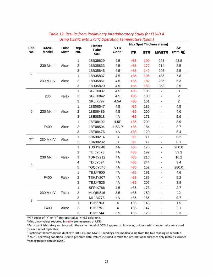
Table 12 and Table 13 list the complete set of data collected from the reporting laboratories for reference Fluids A and B, respectively (Laboratory number zero is UDRI, all other laboratory identities have been blinded for reporting purposes). There are a few striking observations from these data: 1) all but five of the 61 heater tubes
generated at 275C using Fluid A (Table 12) produce a failing rating from all reported methods (VTR, ITR, ETR, and MWETR), and those five heater tubes only pass using the
ITR (they fail via VTR and ETR); 2) all 44 heater tubes generated at 275C using Fluid B (Table 13) produce a passing rating from at least one evaluation technique. That is to say that Fluid A produces a consistent heater tube failing result and Fluid B produces a consistent passing heater tube result across all laboratories and all apparatus types; Figure 12 through Figure 15 emphasize and characterize these points in more detail.
23
Figure 12 shows a box and whisker chart of metrology results for Fluid A heater tubes. Quartile calculations were performed using an exclusive median, and the mean value is shown on the chart as an ‘X’. Ranges of the reported maximum spot thickness, with respect to analytical technique, are variable for the Fluid A results (Figure 12 and Table 10). Some of this variance is due to the fact that 42 (out of 61) of the heater tubes were given a non-numeric rating value of >85 nm via the ITR; and therefore, higher thickness deposits were excluded in the numeric ranges (thus skewing the distribution to lower values for the ITR). Similarly, we have experienced detector saturation with the ETR between about 180 to 220 nm; therefore, thick deposits (≥220 nm) become under reported and can again skew the average value. Results for the MWETR assessment gave both the highest average value, but also the greatest range of values. It is unclear from these data which metrology method produces the most accurate result, nevertheless, rating values for Fluid A were consistently well above the typical failure value of 85 nm regardless of rating technique used.
Figure 12. Box and whisker plot of results for Fluid A; 42 tubes produced an ITR value of >85 nm which are excluded from the plot data.
Table 10. Statistical D3241 Results at 275C for Fluid A
In a similar fashion, Figure 13 and Table 11 show metrology results for Fluid B. What is immediately apparent from these data is how similar the rating results are using ETR, ITR, and even the MWETR (note the small sample population) when the max spot thickness is less than 85 nm. The mean max spot thickness values, and standard deviations, for Fluid B listed in Table 11 show equivalency of the aggregated values among the three metrology methods with the average max spot value being reported between about 50 to 60 nm.
Figure 13. Box and whisker plot of results for Fluid B; one heater tube produced an ITR value of >85 nm which is excluded from the plot data.
Table 11. Statistical D3241 Results at 275C of Fluid B
The agreement demonstrated by the heater tube mean values from multiple metrology methods should not overshadow the overall range of values recorded for the individual samples in this study. In fact, an attempt to capture potential factors involved in test variability, e.g., heater tube manufacture, instrument make/model, reference fluid deposit level, and laboratory, was built into the pre-ILS sample matrix. While it is outside
25
the scope of this project to analyze these data (see Table 12 and Table 13) in terms of characterizing the variability of D3241 itself, we submit that future efforts could use the data contained in this report to investigate the influence of these potential sources of variability. Instead, Figure 14 and Figure 15 show parity plots of numeric heater tube ratings for ETR versus ITR and ETR versus VTR, respectively, to demonstrate the breadth of values recorded. In theory, all of the data should collapse onto two points, i.e., singular values for Fluid A and Fluid B. In both Figure 14 and Figure 15, tubes that were rated as abnormal (A) or peacock (P) are highlighted in green. Again, since 42 heater tubes for Fluid A were rated as >85 nm using the ITR these values could not be plotted. While these two figures both demonstrate the positive correlation between rating techniques, the primary observation we are highlighting is the overall range of values for each identical batch of sample fluid. While the overwhelming majority of heater tube samples conform to Fluid A = Fail and Fluid B = Pass—independent of the rating method—the actual values recorded span a significant range of thicknesses. The cause of the large range in thicknesses (for both Fluid A and Fluid B) is believed to be due to both instrument/test specific factors and the stochastic nature of thermal stability deposition processes.
Figure 14. Parity plot of metrology rating results for heater tubes with numeric values; single abnormal (A) tube rating—with numeric results—highlighted in green.
26
Figure 15. Numeric heater tube results via ETR versus VTR codes for both Fluids A and B; A and P visual ratings—with numeric results—highlighted in green, “<” and “>” codes recorded as –/+ 0.5. While surface deposition of D3241 tests was given as a primary concern, evaluation of pressure drop was a secondary item of interest for the candidate reference fluid(s).
Figure 16 shows histograms of P values (listed in Table 12 and Table 13) for Fluid A and Fluid B. Fluid A provides a pressure drop of >1 mmHg for all but one run and five runs
gave P values >25 mmHg. Fluid B produces significantly less pressure drop with the
overwhelming majority of samples giving less than 1 mmHg P (the reason for the Fluid
B outlier of 250.1 mmHg remains unknown). Based on these observations, if higher P values are desired then it is recommended that higher temperatures or alternative formulations be further explored (see for example Figure 3 and Table 5).
27
Figure 16. Histogram of pressure difference, P, measurements for: a) Fluid A, and b)
Fluid B for ASTM D3241 runs at 275C (data tabulated in Table 12 and Table 13).
A B
28
Table 12. Results from Preliminary Interlaboratory Study for FLUID A
Using D3241 with 275C Operating Temperature
Lab No.
D3241 Model
Tube Mnfr
Rep. No.
Heater Tube S/N
VTR Code1
Max Spot Thickness2 (nm) ΔP
(mmHg) ITR ETR MWETR
0 230 Mk III Falex
1 SIFIX148 4.5 >85 208 - 5.5
2 SIFIX051 4 >85 197 - 10.1
3 SIBIX387 4 >85 190 - 9.0
4 SIFIX133 3.5 >85 216 - 21.1
1
230 Mk III Falex
1 TAKIX293 3.5 >85 131 - 5.3
2 TAKIX292 3.5 87 116 - 4.6
3 TAJIX258 3.5 60 142 - 5.0
230 Mk IV Alcor
1 20A02188 3.5 79 104 - 1.9
2 20A02204 3.5 64 151 - 1.9
3 20A02165 3.5 76 107 - 1.9
F400 Falex
1 SLUIX976 4 >85 155 - 4.0
2 SLUIX192 3.5 64 121 - 4.3
3 SLUIX407 3.5 85 117 - 2.6
2
230 Mk III3 Alcor
1 18B40762 4 >85 216 - 3.7
2 19F23837 4 >85 213 - 5.8
3 19F23855 4 >85 210 - 3.1
230 Mk III3 Alcor
1 19F24150 4 >85 213 - 3.3
2 19F24183 4 >85 212 - 3
3 19F24180 4 >85 219 - 6.6
3†
230 Mk III Alcor
1 19G38323 4 105 181 222 8.2
2 19G38245 3.5 87 127 196 2.5
3 19G38274 3A 89 146 151 3.1
230 Mk III Falex
1 GENEU076 3A >85 189 349 1.3
2 GENEU028 3 103 195 474 1.5
3 GELEU214 3.5 218 207 276 2.4
4
230 Mk IV3 Alcor
1 19I60711 4 160 178 - 195.8
2 19I60682 4 158 188 - 24.6
3 19I60677 4 184 228 - 7.1
4 19J74473 4 112 172 - 6.6
230 Mk IV3 Alcor
1 19I60679 4 144 209 - 9.1
2 19I60694 4 159 210 - 6.4
3 19I60674 4 152 217 - 7.4
29
Table 12. Results from Preliminary Interlaboratory Study for FLUID A
Using D3241 with 275C Operating Temperature (Cont.)
Lab No.
D3241 Model
Tube Mnfr
Rep. No.
Heater Tube S/N
VTR Code1
Max Spot Thickness2 (nm) ΔP
(mmHg) ITR ETR MWETR
5
230 Mk III Alcor
1 18B35629 4.5 >85 190 226 43.8
2 18B35833 4.5 >85 172 214 2.5
3 18B35845 4.5 >85 149 206 2.5
230 Mk IV Alcor
1 18B35837 4.5 >85 196 435 7.8
2 18B35851 4.5 >85 182 286 5.3
3 18B35820 4.5 >85 183 358 2.5
6
230 Falex
1 SGLIX037 4.5 >85 185 - 3
2 SGLIX842 4.5 >85 180 - 2
3 SKLIX797 4.5A >85 161 - 2
230 Mk III Alcor
1 18E08547 4.5 >85 189 - 4.5
2 18E08486 4.5 >85 200 - 4.6
3 18E08518 4A >85 171 - 5.9
F400 Alcor
1 18E08492 4.5P >85 209 - 8.9
2 18E08504 4.5A,P >85 184 - 8.7
3 18E08476 4A >85 120 - 5.4
7†† 230 Mk IV Alcor 1 19A38214 3 90 80 - 0.2
2 19A38232 3 89 88 - 0.1
8
230 Mk III Falex
1 TDXJY840 4A >85 175 - 280.0
2 TEIJY073 4A >85 199 - 53.3
3 TDRJY212 4A >85 216 - 16.2
4 TDIJY694 4A >85 244 - 3.4
5 TGQJY646 4A >85 152 - 280.0
F400 Falex
1 TEJJY900 4A >85 191 - 4.6
2 TEHJY207 4A >85 189 - 5.2
3 TEJJY525 4A >85 206 - 3.8
9
230 Mk IV Falex
1 SFRIX786 4.5 >85 173 - 2.7
2 MLQBI816 3.5 >85 159 - 12
3 MLJBI778 4A >85 185 - 0.7
F400 Alcor
1 19I62763 4 >85 143 - 1.5
2 19I62751 4 >85 147 - 2.1
3 19I62744 3.5 >85 123 - 2.3 1 VTR codes of “<” or “>” are reported as -/+ 0.5 color unit. 2 Metrology values reported in red were measured at UDRI. 3 Participant laboratory ran tests with the same model of D3241 apparatus, however, unique serial number units were used for each set of replicates. † Participant laboratory ran duplicate ITR, ETR, and MWETR readings, the median value from the two readings is reported. †† 260C operating condition used to generate data; values included in table for informational purposes only (data is excluded from aggregate data analysis).
30
Table 13. Results from Preliminary Interlaboratory Study for FLUID B
Using D3241 with 275C Operating Temperature
Lab No.
D3241 Model
Tube Mnfr
Rep. No.
Heater Tube S/N
VTR Code1
Max Spot Thickness2 (nm) ΔP
(mmHg) ITR ETR MWETR
0 230 Mk III Falex
1 SIFIX207 1.5 45 58 0.8
2 SIBIX562 1 42 54 3.4
3 SIBIX377 1 40 53 1.5
4 SIAIX397 1 52 74 1.4
1
230 Mk III Falex
1 SLUIX227 2.5 34 36 0.6
2 SLUIX693 2.5 31 30 0.3
3 SLUIX136 2 21 32 0.2
230 Mk IV Alcor
1 20A02287 1.5 37 45 0.0
2 20A02292 1.5 36 35 0.6
3 20A02314 1.5 34 31 0.0
F400 Falex
1 SLUIX460 2.5 40 67 0.7
2 SLUIX691 3 68 63 0.5
3 SLUIX619 2 18 41 0.8
2
230 Mk III3 Alcor
1 19F23847 1 36 33 0
2 19F23861 1 39 42 0
3 19F23849 0.5 41 47 0
230 Mk III3 Alcor
1 19F24186 1 45 50 0
2 19F24221 0.5 62 58 0
3 19F24192 0.5 71 52 0
3†
230 Mk III Alcor
1 19G38246 1 38 43 54 0
2 19G38269 1.5 38 52 57 0
3 19G38342 1 57 71 65 0
230 Mk III Falex
1 QENEU244 2.5 76 77 73 0
2 QENEU160 2.5 66 72 57 0
3 QENEU563 2.5 64 69 58 0
4
230 Mk IV3 Alcor
1 19I60685 2 73 150 0.0
2 19I60684 2 73 187 0.0
3 19J74466 2 75 67 0.0
230 Mk IV3 Alcor
1 19I60686 2 73 68 250.1
2 19I60688 2 74 82 2.7
3 19I60681 2 73 73 2.5
4 19J74464 2 77 77 1.0
31
Table 13. Results from Preliminary Interlaboratory Study for FLUID B
Using D3241 with 275C Operating Temperature (Cont.)
Lab No.
D3241 Model
Tube Mnfr
Rep. No.
Heater Tube S/N
VTR Code1
Max Spot Thickness2 (nm) ΔP
(mmHg) ITR ETR MWETR
8
230 Mk III Falex
1 TGWJY112 2 47 47 0.0
2 TJZJY145 1.5 52 44 0.7
3 TKUJY138 2 58 74 0.2
F400 Falex
1 TGWJY768 1.5 46 57 2.3
2 TGAJY185 1.5 36 58 0.5
3 TGQJY832 1.5 32 40 0.5
9
230 Mk IV Falex
1 SFYIX055 1 37 37 0.1
2 SFRIX372 1 36 46 0
3 SGAIX195 3 79 85 0
F400 Alcor
1 19I62801 1A >85 54 0.1
2 19I62764 1.5 36 40 0.8
3 19I62762 1 46 46 0 1 VTR codes of “<” or “>” are reported as -/+ 0.5 color unit. 2 Metrology values reported in red were measured at UDRI. 3 Participant laboratory ran tests with the same model of D3241 apparatus, however, unique serial number units were used for each set of replicates. † Participant laboratory ran duplicate ITR, ETR, and MWETR readings, the median value from the two readings is reported.
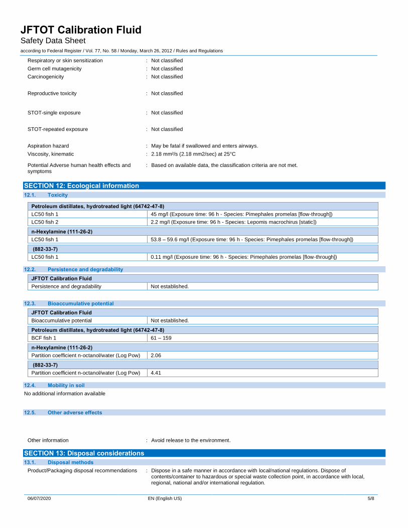
Environmental, Health, and Safety Assessment It was requested that UDRI make a first attempt at characterizing the environmental, health, and safety (EHS) aspects of the candidate reference fluid(s). Haltermann Solutions was consulted and kindly produced a draft safety data sheet (SDS) for Fluids A and B, which are the most promising candidate mixtures, i.e., Exxsol D80 with hexylamine, dimethyl aniline, and diphenyl disulfide. A copy of the SDS can be found in Appendix B of this report.
Transition Plan The original RFP requested the development of a transition plan for any potential reference fluid(s). Again, UDRI consulted with Haltermann Solutions—a trusted manufacture of specialty fuels and test/reference fuels for industry—with regard to product feasibility. Haltermann Solutions believe it is feasible to produce a reference fluid(s) according to the specifications give in this report. Their assessment is based on prior experience and includes consideration of: the procurement of aliphatic solvent, blending the instigating mixture with the solvent, and containerizing the reference fluid blend at appropriate volumes (~1 L) for market. None of our discussions addressed cost
32
analysis, e.g., pricing and market analysis, as this is outside the scope of CRC and this project. In addition to commercial production of the reference fluid, it is suggested that the concept of a reference fluid be brought before an appropriate commercial standards organization, e.g., ASTM and EI, so that consensus can be achieved within the industry. While UDRI does not currently intend to bring this concept to ASTM or EI directly, we are open to working with parties who would like to further the concept of a reference fluid for commercial standard approval.
33
CONCLUSIONS We have reported on the development of a reference fluid for use with ASTM D3241. The original observations and development, conducted by UDRI, were performed using a single Mark III Alcor JFTOT® with Falex heater tubes. Results indicate that a mixture of nitrogen and sulfur containing heteroatomic compounds can be added to an aliphatic solvent to produce a consistent, and reproducible level of deposition—and a detectible
amount of pressure difference with the same solution—at 275C using the ASTM D3241 method. The instigating heteroatomic compounds, i.e., hexylamine, dimethyl aniline, and diphenyl disulfide, and solvents, e.g., Exxsol D80, are easily obtainable at laboratory quantities and at the appropriate purity for direct use. The mixture appears to be stable over an extended period of storage (12 weeks at 43°C). Preliminary interlaboratory study of both a high (Fluid A) and low (Fluid B) concentration reference fluids indicates excellent agreement for pass/fail surface deposit results; however, absolute deposit thickness vary significantly. While outside the scope of this work, the data collected in the pre-ILS could be used to help determine repeatability (r) and reproducibility (R) of the D3241 method directly. Regardless, the high concentration fluid consistently produced failing results >>85 nm deposit thickness, while the low concentration fluid produced deposits over a range of about 30 to 70 nm. Pressure drop results were more significant for the high concentration reference fluid. Alternatively, it was found that significant pressure drop could be generated using an N & S mixture at
300C.
34
ACKNOWLEDGEMENTS The authors thank the following list of individuals and corporations for their support in the preliminary interlaboratory study:
Company Individuals
Air BP Alisdair Clark Michael Zahnhausen Chevron Doug Cyr Krege Christison
DLA-E Mike Domen ExxonMobil Research and Engineering Dan Kadlecek
NAVAIR Andy McDaniel Kevin Bowes Nobil Petroleum Testing Madi Mohtadi
PAC Gordon Chiu David Anderson QETE, Canada Nathalie Gaudet Marie Robichaud
SwRI Tim Kidwell
The authors thank the valuable discussions and SDS contribution of Indresh Mathur of Haltermann Solutions. The authors thank the CRC technical panel for useful suggestions and feedback. Finally, the authors thank Erik Weber, Tim Edwards, and Paul Wrzesinski of the Fuels and Energy Branch (RQTF) of the Air Force Research Laboratory (AFRL) for use of AFRL facilities throughout this project (CRADA No. 10-223-RZ-01).
35
REFERENCES ASTM International. Interlaboratory Study to Establish Precision Statements for ASTM D3241, Standard Test Method for Thermal Oxidation Stability of Aviation Turbine Fuels; Research Report D02-1309; ASTM: West Conshohocken, PA, August 1993. Bower, K. JF1603 Crosscheck Thermal Stability. Presented at the ASTM D02 Meeting, Lake Buena Vista, FL, December 2016. Bower, K. Presented at the UK MoD Aviation Fuels Committee Meeting, London, UK, March 19, 2019. Hazlett, R.N. Thermal Oxidation Stability of Aviation Turbine Fuels; Monograph 1; ASTM International: Ann Arbor, MI, 1991. Kuprowicz, N.J.; Zabarnick, S.; West, Z.J.; Ervin, J.S. The Use of Measured Species Class Concentrations with Chemical Kinetic Modeling for the Prediction of Autoxidation and Deposition of Jet Fuels. Energy & Fuels. 2007, 21 (2), 530–544. DOI:10.1021/ef060391o Lacey, P.; Gail, S.; Grinstead, D.; Daveau, C.; Caprotti, R.; Dallanegra, R.; Pigeon, D. Use of a Laboratory Scale Test to Study Internal Diesel Injector Deposits; SAE Technical Paper 2016-01-2247; SAE International, 2016. DOI: 10.4271/2016-01-2247. Reid, J.; Barker, J. Understanding Polyisobutylene Succinimides (PIBSI) and Internal Diesel Injector Deposits; SAE Technical Paper 2013-01-2682; SAE International, 2013. DOI: 10.4271/2013-01-2682
Sander, Z.H.; West, Z.J.; Ervin, J.S.; Zabarnick, S. Experimental and Modeling Studies of Heat Transfer, Fluid Dynamics, and Autoxidation Chemistry in the Jet Fuel Thermal Oxidation Tester (JFTOT). Energy & Fuels. 2015, 29 (11), 7037–7047. DOI: 10.1021/acs.energyfuels.5b01679
Taylor, S.E. An Alternative View of the Thermal Oxidative Stability of Jet Fuels. Petroleum Chemistry Division Preprints. 2002, 47(3), 165–169. Zabarnick, S.; West, Z.J.; Shafer, L.; Striebich, R.C.; Mueller, S.S.; Griesenbrock, M.M. Role of Nitrogen and Sulfur Species in Jet Fuel Thermal Stability. Presented at the CRC Aviation Meeting, Alexandria, VA, 2–5 May 2016.
36
Zabarnick, S.; West, Z.; Shafer, L.; Striebich, R.; Mueller, S.; Griesenbrock, M. Role of Heteroatomic Species in Jet Fuel Thermal Stability – Real Fuel Studies. Presented at the CRC Aviation Meeting, Portland, OR, May 2017. Zabarnick, S.; West, Z.J.; Shafer, L.M.; Mueller, S.S.; Striebich, R.C.; Wrzesinski, P.J. Studies of the Role of Heteroatomic Species in Jet Fuel Thermal Stability: Model Fuel Mixtures and Real Fuels. Energy & Fuels. 2019, 33, 8557–8565. DOI: 10.1021/acs.energyfuels.9b02345
37
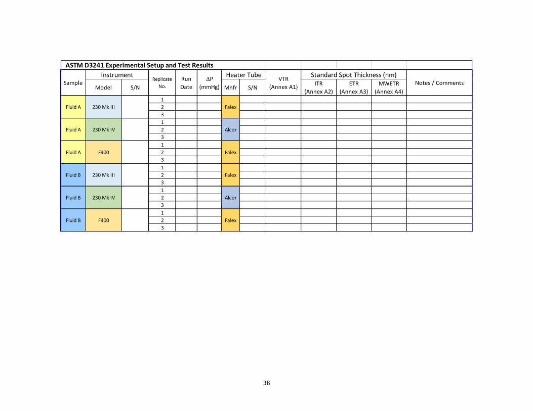
APPENDIX A: PRE-ILS PARTICIPANT INSTRUCTIONS AND RESULTS TEMPLATE
Participant Instructions:
1) Please fill in all information regarding experimental setup and test results on the "User Data" worksheet of this file (see example below).
2) Each fluid shall be run in triplicate using the same experimental setup, i.e., on the same instrument, using a new heater tube of the same manufacture for each run.
3) Instrument operating conditions (for all runs) are as follows:
Temperature = 275°C
Flow Rate = 3.0 mL/min
Test Duration = 150 minutes (2.5 hours)
4) Evaluate heater tubes using as many evaluation techniques as are available to you and report the results in the provided spreadsheet.
5) Please ship all heater tube specimens back to UDRI once you have finished performing all testing. (Ship to: ATTN: Zach West, UDRI, 1529 Brown St., Dayton, OH USA 45469-0043)
Thank you for participating in this pre-ILS study. As a participant you will receive up to two candidate fluids (labeled 'Fluid A' and 'Fluid B'); note that
not all participants will receive both fluids. These fluids contain different levels of active ingredient, so please do not co-mingle different fluid types,
i.e., do not combined Fluid A and Fluid B. Please run all fluid samples according to ASTM D3241-19 using the operating conditions given below. If
there are any questions about this study, or your role in it, please direct any inquiries to: Dr. Zach West ([email protected], ph: (937)-255-4062).
Standard Spot Thickness (nm)Notes / Comments
Fluid A 230 Mk III 741-0000 Falex
Run DateSampleInstrument
Replicate
No.P (mmHg)
Heater TubeVTR
(Annex A1)
38
Model S/N Mnfr S/NITR
(Annex A2)
ETR
(Annex A3)
MWETR
(Annex A4)1
2
3
1
2
3
1
2
3
1
2
3
1
2
3
1
2
3
ASTM D3241 Experimental Setup and Test Results
230 Mk III
230 Mk IV
F400
Instrument
Fluid A
Fluid A
Fluid A
Run
Date
Alcor
Falex
SampleReplicate
No.
P
(mmHg)
Heater Tube
Falex
Alcor
Fluid B
230 Mk III
230 Mk IV
F400
Fluid B
Fluid B
Falex
Standard Spot Thickness (nm)Notes / Comments
Falex
VTR
(Annex A1)
39
APPENDIX B: DRAFT SAFETY DATA SHEET (SDS)
JFTOT Calibration Fluid Safety Data Sheet according to Federal Register / Vol. 77, No. 58 / Monday, March 26, 2012 / Rules and Regulations
Issue date: 06/07/2020
06/07/2020 EN (English US) Page 1
SECTION 1: Identification
1.1. Identification Product form : Mixture
Trade name : JFTOT Calibration Fluid
1.2. Recommended use and restrictions on use No additional information available
1.3. Supplier Haltermann Solutions™ 15600 West Hardy Rd. Houston, TX 77060 - USA
1.4. Emergency telephone number Emergency number : 24 HR CHEMTREC: 1-800-424-9300; Emergency Assistance: 1-800-969-2542 (8 AM to 5 PM
CDT)
SECTION 2: Hazard(s) identification
2.1. Classification of the substance or mixture
GHS US classification Flammable liquids Category 4 H227 Combustible liquid
Aspiration hazard Category 1 H304 May be fatal if swallowed and enters airways
Full text of H statements : see section 16
2.2. GHS Label elements, including precautionary statements GHS US labeling
Hazard pictograms (GHS US) :
Signal word (GHS US) : Danger
Hazard statements (GHS US) : H227 - Combustible liquid H304 - May be fatal if swallowed and enters airways
Precautionary statements (GHS US) : P210 - Keep away from heat, hot surfaces, sparks, open flames and other ignition sources. No smoking.
P280 - Wear protective gloves/protective clothing/eye protection/face protection. P301+P310 - If swallowed: Immediately call a poison center or doctor. P331 - Do NOT induce vomiting.
P370+P378 - In case of fire: Use media other than water to extinguish. P403+P235 - Store in a well-ventilated place. Keep cool. P405 - Store locked up.
P501 - Dispose of contents/container to hazardous or special waste collection point, in accordance with local, regional, national and/or international regulation.
2.3. Other hazards which do not result in classification No additional information available
2.4. Unknown acute toxicity (GHS US) Not applicable
SECTION 3: Composition/Information on ingredients
3.1. Substances Not applicable
3.2. Mixtures
Name Product identifier % Petroleum distillates, hydrotreated light
JFTOT Calibration Fluid Safety Data Sheet according to Federal Register / Vol. 77, No. 58 / Monday, March 26, 2012 / Rules and Regulations
06/07/2020 EN (English US) 2/8
Name Product identifier %
(CAS-No.) 882-33-7 0.00125 – 0.0025
3,5-Dimethylaniline
(CAS-No.) 108-69-0 0.00125 – 0.0025
Full text of hazard classes and H-statements : see section 16
SECTION 4: First-aid measures
4.1. Description of first aid measures First-aid measures general : Never give anything by mouth to an unconscious person. If you feel unwell, seek medical
advice (show the label where possible).
First-aid measures after inhalation : Allow affected person to breathe fresh air. Allow the victim to rest.
First-aid measures after skin contact : Remove affected clothing and wash all exposed skin area with mild soap and water, followed by warm water rinse.
First-aid measures after eye contact : Rinse immediately with plenty of water. Obtain medical attention if pain, blinking or redness persists.
First-aid measures after ingestion : Rinse mouth. Do NOT induce vomiting. Immediately call a poison center or doctor/physician.
4.2. Most important symptoms and effects (acute and delayed) Potential Adverse human health effects and symptoms
: Based on available data, the classification criteria are not met.
4.3. Immediate medical attention and special treatment, if necessary No additional information available
SECTION 5: Fire-fighting measures
5.1. Suitable (and unsuitable) extinguishing media Suitable extinguishing media : Foam. Dry powder. Carbon dioxide. Water spray. Sand.
Unsuitable extinguishing media : Do not use a heavy water stream.
5.2. Specific hazards arising from the chemical Fire hazard : Combustible liquid.
Explosion hazard : May form flammable/explosive vapor-air mixture.
5.3. Special protective equipment and precautions for fire-fighters Firefighting instructions : Use water spray or fog for cooling exposed containers. Exercise caution when fighting any
chemical fire. Prevent fire-fighting water from entering environment.
Protection during firefighting : Do not enter fire area without proper protective equipment, including respiratory protection.
SECTION 6: Accidental release measures
6.1. Personal precautions, protective equipment and emergency procedures General measures : Remove ignition sources. Use special care to avoid static electric charges. No open flames. No
smoking.
6.1.1. For non-emergency personnel Emergency procedures : Evacuate unnecessary personnel.
6.1.2. For emergency responders Protective equipment : Equip cleanup crew with proper protection.
Emergency procedures : Ventilate area.
6.2. Environmental precautions Prevent entry to sewers and public waters. Notify authorities if liquid enters sewers or public waters.
6.3. Methods and material for containment and cleaning up Methods for cleaning up : Soak up spills with inert solids, such as clay or diatomaceous earth as soon as possible. Collect
spillage. Store away from other materials.
6.4. Reference to other sections See Heading 8. Exposure controls and personal protection.
SECTION 7: Handling and storage
7.1. Precautions for safe handling Additional hazards when processed : Handle empty containers with care because residual vapors are flammable. Keep away from
heat/sparks/open flames/hot surfaces. - No smoking.
JFTOT Calibration Fluid Safety Data Sheet according to Federal Register / Vol. 77, No. 58 / Monday, March 26, 2012 / Rules and Regulations
06/07/2020 EN (English US) 3/8
Precautions for safe handling : Wash hands and other exposed areas with mild soap and water before eating, drinking or smoking and when leaving work. Provide good ventilation in process area to prevent formation of vapor. No open flames. No smoking.
7.2. Conditions for safe storage, including any incompatibilities Technical measures : Proper grounding procedures to avoid static electricity should be followed.
Storage conditions : Keep only in the original container in a cool, well ventilated place away from : Heat sources,
Ignition sources, Incompatible materials. Keep container closed when not in use. Keep in fireproof place.
Proper Shipping Name (DOT) : Combustible liquid, n.o.s.
DISTILLATES (PETROLEUM), HYDROTREATED LIGHT
Class (DOT) : Comb Liq - Combustible liquid
Packing group (DOT) : III - Minor Danger
DOT Packaging Non Bulk (49 CFR 173.xxx) : 203
DOT Packaging Bulk (49 CFR 173.xxx) : 241
DOT Symbols : D - Proper shipping name for domestic use only, or to and from Canada,G - Identifies PSN
requiring a technical name
DOT Special Provisions (49 CFR 172.102) : 148 - Except for transportation by aircraft, when transported as a limited quantity or a consumer commodity, the maximum net capacity specified in §173.150(b)(2) of this subchapter for inner packaging may be increased to 5 L (1.3 gallons).
IB3 - Authorized IBCs: Metal (31A, 31B and 31N); Rigid plastics (31H1 and 31H2); Composite (31HZ1 and 31HA2, 31HB2, 31HN2, 31HD2 and 31HH2). Additional Requirement: Only liquids with a vapor pressure less than or equal to 110 kPa at 50 C (1.1 bar at 122 F), or 130 kPa at 55
C (1.3 bar at 131 F) are authorized, except for UN2672 (also see Special Provision IP8 in Table 2 for UN2672). T1 - 1.5 178.274(d)(2) Normal............. 178.275(d)(2)
TP1 - The maximum degree of filling must not exceed the degree of filling determined by the following: Degree of filling = 97 / 1 + a (tr - tf) Where: tr is the maximum mean bulk temperature during transport, and tf is the temperature in degrees celsius of the liquid during filling.
DOT Quantity Limitations Cargo aircraft only (49 CFR 175.75)
: 220 L
DOT Vessel Stowage Location : A - The material may be stowed ‘‘on deck’’ or ‘‘under deck’’ on a cargo vessel and on a passenger vessel.
Other information : Transportation Notes: Material is not regulated by the U.S. DOT for ground transportation within
the U.S. if shipped in non-bulk packaging (<119 gallons).
Transport by sea
Not regulated
Air transport
Not regulated
SECTION 15: Regulatory information
15.1. US Federal regulations
All components of this product are listed, or excluded from listing, on the United States Environmental Protection Agency Toxic Substances Control Act (TSCA) inventory
This product or mixture is not known to contain a toxic chemical or chemicals in excess of the applicable de minimis concentration as specified in 40 CFR §372.38(a) subject to the reporting requirements of section 313 of Title III of the Superfund Amendments and Reauthorization Act of
1986 and 40 CFR Part 372.
15.2. International regulations
CANADA
JFTOT Calibration Fluid Safety Data Sheet according to Federal Register / Vol. 77, No. 58 / Monday, March 26, 2012 / Rules and Regulations
06/07/2020 EN (English US) 7/8
Petroleum distillates, hydrotreated light (64742-47-8) Listed on the Canadian DSL (Domestic Substances List)
n-Hexylamine (111-26-2) Listed on the Canadian DSL (Domestic Substances List)
(882-33-7) Listed on the Canadian DSL (Domestic Substances List)
3,5-Dimethylaniline (108-69-0) Listed on the Canadian NDSL (Non-Domestic Substances List)
EU-Regulations
Petroleum distillates, hydrotreated light (64742-47-8) Listed on the EEC inventory EINECS (European Inventory of Existing Commercial Chemical Substances)
n-Hexylamine (111-26-2) Listed on the EEC inventory EINECS (European Inventory of Existing Commercial Chemical Substances)
(882-33-7) Listed on the EEC inventory EINECS (European Inventory of Existing Commercial Chemical Substances)
3,5-Dimethylaniline (108-69-0) Listed on the EEC inventory EINECS (European Inventory of Existing Commercial Chemical Substances)
National regulations
Petroleum distillates, hydrotreated light (64742-47-8) Listed on the AICS (Australian Inventory of Chemical Substances) Listed on IECSC (Inventory of Existing Chemical Substances Produced or Imported in China) Listed on KECL/KECI (Korean Existing Chemicals Inventory)
Listed on NZIoC (New Zealand Inventory of Chemicals) Listed on PICCS (Philippines Inventory of Chemicals and Chemical Substances) Listed on INSQ (Mexican National Inventory of Chemical Substances)
Listed on the TCSI (Taiwan Chemical Substance Inventory)
n-Hexylamine (111-26-2) Listed on the AICS (Australian Inventory of Chemical Substances) Listed on IECSC (Inventory of Existing Chemical Substances Produced or Imported in China)
Listed on the Japanese ENCS (Existing & New Chemical Substances) inventory Listed on the Japanese ISHL (Industrial Safety and Health Law) Listed on KECL/KECI (Korean Existing Chemicals Inventory)
Listed on NZIoC (New Zealand Inventory of Chemicals) Listed on PICCS (Philippines Inventory of Chemicals and Chemical Substances) Listed on the TCSI (Taiwan Chemical Substance Inventory)
(882-33-7) Listed on the AICS (Australian Inventory of Chemical Substances)
Listed on IECSC (Inventory of Existing Chemical Substances Produced or Imported in China) Listed on the Japanese ENCS (Existing & New Chemical Substances) inventory Listed on the Japanese ISHL (Industrial Safety and Health Law)
Listed on KECL/KECI (Korean Existing Chemicals Inventory) Listed on NZIoC (New Zealand Inventory of Chemicals) Listed on PICCS (Philippines Inventory of Chemicals and Chemical Substances)
Listed on INSQ (Mexican National Inventory of Chemical Substances) Listed on the TCSI (Taiwan Chemical Substance Inventory)
3,5-Dimethylaniline (108-69-0) Listed on the AICS (Australian Inventory of Chemical Substances) Listed on IECSC (Inventory of Existing Chemical Substances Produced or Imported in China)
Listed on the Japanese ENCS (Existing & New Chemical Substances) inventory Listed on the Japanese ISHL (Industrial Safety and Health Law) Listed on KECL/KECI (Korean Existing Chemicals Inventory)
Listed on the TCSI (Taiwan Chemical Substance Inventory)
15.3. US State regulations
California Proposition 65 - This product does not contain any substances known to the state of California to cause cancer, developmental and/or reproductive harm
JFTOT Calibration Fluid Safety Data Sheet according to Federal Register / Vol. 77, No. 58 / Monday, March 26, 2012 / Rules and Regulations
06/07/2020 EN (English US) 8/8
Component State or local regulations
n-Hexylamine(111-26-2) U.S. - Massachusetts - Right To Know List; U.S. - New Jersey - Right to Know Hazardous Substance List; U.S. - Pennsylvania - RTK (Right to Know) List
SECTION 16: Other information
according to Federal Register / Vol. 77, No. 58 / Monday, March 26, 2012 / Rules and Regulations
Other information : None.
Full text of H-phrases:
H227 Combustible liquid
H304 May be fatal if swallowed and enters airways
SDS US (GHS HazCom 2012)
This information is furnished without warranty, expressed or implied except that it is accurate to the best knowledge of Haltermann Solutions™. The data on this sheet are re lated only to the specific material herein. Haltermann Solutions™ assumes no responsibility for the use or reliance upon these data.