Published in SMTA Int’l Proceedings, Orlando, FL, Oct. 2007. CREEP CORROSION ON LEAD-FREE PRINTED CIRCUIT BOARDS IN HIGH SULFUR ENVIRONMENTS Randy Schueller, Ph.D. Dell Inc., Austin, Texas [email protected]ABSTRACT The material and process changes required to eliminate lead from electronics as required by Restriction of Hazardous Substance (RoHS) legislation was likely to result in new quality and reliability issues. The industry had over 50 years experience with tin-lead solders. Changing to different solder alloys, fluxes, termination plating materials, PCB surface finishes and soldering temperatures in a span of 1-2 years was a high risk undertaking. Although many potential issues were uncovered and resolved, one new failure mechanism was not foreseen by the industry. Immersion silver (ImAg) was widely adopted to replace hot air solder level (HASL) as the surface finish on PCBs. ImAg was known to tarnish when exposed to sulfur, but it was a surprise to find that it suffers extensive creep corrosion when the sulfur and humidity levels are high enough. Failures can occur in as little as a few weeks in industries such as rubber manufacturing, water treatment, paper mills or fertilizer production, among others. This paper uncovers the root cause of the creep corrosion mechanism and shows how to eliminate it. Corrosive environments were measured and the results of field testing of various surface finishes in these environments is shared. Also presented are some more effective corrosion test methods currently under development. Keywords: immersion silver, creep, corrosion, Pb-free, corrosion testing. INTRODUCTION Many millions of lead-free desktop and notebook systems, and related peripherals, have been put into service by Dell starting in 2005, a year prior to the effective date of the RoHS legislation. A large amount of resources were invested in optimizing and qualifying lead-free (LF) assemblies. Testing to failure (with use of HALT, shock & vibration, torsion, and thermal cycling) followed by detailed failure analysis enabled implementation of risk mitigation strategies to compensate for the strain sensitivity of high modulus lead-free solder alloys. In addition, various techniques were implemented to minimize the risk of tin whiskers (another known risk with LF products). As a result of these efforts, field data shows the overall quality of Dell’s lead-free products to be as good, and in some cases, better than the previous generation of tin-lead products. However, one new failure mechanism caused by the LF transition was not foreseen by Dell or the industry. It was discovered that lead-free (LF) products with immersion silver (ImAg) surface finish will creep corrode in high sulfur industrial environments. Creep corrosion is when a corrosion product (most notably copper or silver sulfide) creeps along a non-corroding surface such as a noble metal or in this case a dielectric. SnPb HASL was the most common surface finish prior to RoHS implementation and this surface finish did not result in creep corrosion in these same environments. ImAg was selected as the replacement by many electronic suppliers because it was readily available, provided good solderability, and was easy to probe (for high in-circuit test yields). It was expected that ImAg would tarnish in the presence of sulfur (Ag 2 S forms on the surface) but this was only a cosmetic concern. Previous studies showed that electrochemical migration was not a problem [1]. Typical mixed flowing gas (MFG) testing also did not show creep corrosion [2]. Thus it was a surprise to the industry when electronics in high sulfur industrial environments would fail rather quickly, some within 4 weeks of being put in service; replacement systems would do the same. Most failures would occur in 2-4 months. Product tracking indicated that if failures did not take place within 6 months, they typically would not fail later from this mechanism. Thus there seemed to be a threshold of sulfur and humidity below which creep corrosion did not occur. High airflow appears to increase creep corrosion, as it is most severe in the direct path of air intake (likely due to more sulfur being made available for reaction). Analysis of creep failures revealed the corrosion product to be fairly resistive, so bridging of two conductors does not cause immediate failure. As the corrosion product increases in thickness, the resistance decreases until functional shorting occurs. For this reason, there are a multitude of symptoms that can take place as a result of creep corrosion (depending on which two conductors are the first to bridge). Additionally, it was found that many corrosion failures passed electrical testing upon arrival from the field (termed CND – cannot duplicate). Upon exposure to high humidity, the failure symptom would reoccur. Resistance measurements showed that when exposed to high humidity, the resistance of the corrosion product dropped from over 10 Mohm to below 1 Mohm. Due to the nature of this failure mechanism it is difficult to identify corrosion failures without close inspection of each board. The majority of creep corrosion failures occurred on hard disk drives (HDD), graphic cards, and motherboards in
Transcript
Published in SMTA Int’l Proceedings, Orlando, FL, Oct. 2007.
CREEP CORROSION ON LEAD-FREE PRINTED CIRCUIT BOARDS IN HIGH SULFUR ENVIRONMENTS
ABSTRACT The material and process changes required to eliminate lead from electronics as required by Restriction of Hazardous Substance (RoHS) legislation was likely to result in new quality and reliability issues. The industry had over 50 years experience with tin-lead solders. Changing to different solder alloys, fluxes, termination plating materials, PCB surface finishes and soldering temperatures in a span of 1-2 years was a high risk undertaking. Although many potential issues were uncovered and resolved, one new failure mechanism was not foreseen by the industry. Immersion silver (ImAg) was widely adopted to replace hot air solder level (HASL) as the surface finish on PCBs. ImAg was known to tarnish when exposed to sulfur, but it was a surprise to find that it suffers extensive creep corrosion when the sulfur and humidity levels are high enough. Failures can occur in as little as a few weeks in industries such as rubber manufacturing, water treatment, paper mills or fertilizer production, among others. This paper uncovers the root cause of the creep corrosion mechanism and shows how to eliminate it. Corrosive environments were measured and the results of field testing of various surface finishes in these environments is shared. Also presented are some more effective corrosion test methods currently under development. Keywords: immersion silver, creep, corrosion, Pb-free, corrosion testing. INTRODUCTION Many millions of lead-free desktop and notebook systems, and related peripherals, have been put into service by Dell starting in 2005, a year prior to the effective date of the RoHS legislation. A large amount of resources were invested in optimizing and qualifying lead-free (LF) assemblies. Testing to failure (with use of HALT, shock & vibration, torsion, and thermal cycling) followed by detailed failure analysis enabled implementation of risk mitigation strategies to compensate for the strain sensitivity of high modulus lead-free solder alloys. In addition, various techniques were implemented to minimize the risk of tin whiskers (another known risk with LF products). As a result of these efforts, field data shows the overall quality of Dell’s lead-free products to be as good, and in some cases, better than the previous generation of tin-lead products. However, one new failure mechanism caused by the LF transition was not foreseen by Dell or the industry. It was discovered that lead-free (LF) products with immersion
silver (ImAg) surface finish will creep corrode in high sulfur industrial environments. Creep corrosion is when a corrosion product (most notably copper or silver sulfide) creeps along a non-corroding surface such as a noble metal or in this case a dielectric. SnPb HASL was the most common surface finish prior to RoHS implementation and this surface finish did not result in creep corrosion in these same environments. ImAg was selected as the replacement by many electronic suppliers because it was readily available, provided good solderability, and was easy to probe (for high in-circuit test yields). It was expected that ImAg would tarnish in the presence of sulfur (Ag2S forms on the surface) but this was only a cosmetic concern. Previous studies showed that electrochemical migration was not a problem [1]. Typical mixed flowing gas (MFG) testing also did not show creep corrosion [2]. Thus it was a surprise to the industry when electronics in high sulfur industrial environments would fail rather quickly, some within 4 weeks of being put in service; replacement systems would do the same. Most failures would occur in 2-4 months. Product tracking indicated that if failures did not take place within 6 months, they typically would not fail later from this mechanism. Thus there seemed to be a threshold of sulfur and humidity below which creep corrosion did not occur. High airflow appears to increase creep corrosion, as it is most severe in the direct path of air intake (likely due to more sulfur being made available for reaction). Analysis of creep failures revealed the corrosion product to be fairly resistive, so bridging of two conductors does not cause immediate failure. As the corrosion product increases in thickness, the resistance decreases until functional shorting occurs. For this reason, there are a multitude of symptoms that can take place as a result of creep corrosion (depending on which two conductors are the first to bridge). Additionally, it was found that many corrosion failures passed electrical testing upon arrival from the field (termed CND – cannot duplicate). Upon exposure to high humidity, the failure symptom would reoccur. Resistance measurements showed that when exposed to high humidity, the resistance of the corrosion product dropped from over 10 Mohm to below 1 Mohm. Due to the nature of this failure mechanism it is difficult to identify corrosion failures without close inspection of each board. The majority of creep corrosion failures occurred on hard disk drives (HDD), graphic cards, and motherboards in
Published in SMTA Int’l Proceedings, Orlando, FL, Oct. 2007.
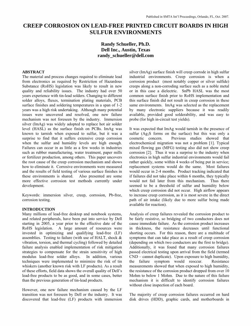
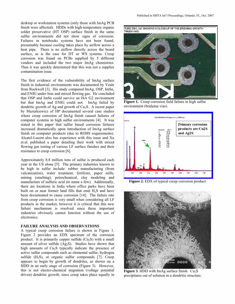
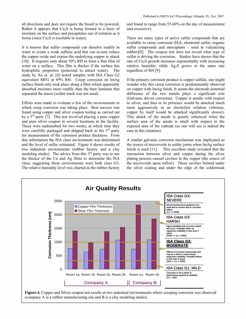
desktop or workstation systems (only those with ImAg PCB finish were affected). HDDs with high-temperature organic solder preservative (HT OSP) surface finish in the same sulfur environments did not show signs of corrosion. Failures in notebooks systems have not been found, presumably because cooling takes place by airflow across a heat pipe. There is no airflow directly across the board surface, as is the case for DT or WS systems. Creep corrosion was found on PCBs supplied by 5 different vendors and included the two major ImAg chemistries. Thus it was quickly determined that this was not a supplier contamination issue. The first evidence of the vulnerability of ImAg surface finish in industrial environments was documented by Veale from Rockwell [3]. His study compared ImAg, OSP, ImSn, and ENIG under bias and mixed flowing gas. He concluded that OSP and ImSn could survive an ISA G2 environment but that ImAg and ENIG could not. ImAg failed by dendritic growth of Ag and growth of Cu2S. A recent paper by Mazurkiewicz of HP documented several case studies where creep corrosion of ImAg finish caused failures of computer systems in high sulfur environments [4]. It was stated in this paper that sulfur based corrosion failures increased dramatically upon introduction of ImAg surface finish on computer products (due to ROHS requirements). Alcatel-Lucent also has experience with this issue and Xu et.al. published a paper detailing their work with mixed flowing gas testing of various LF surface finishes and their resistance to creep corrosion [6]. Approximately 8.8 million tons of sulfur is produced each year in the US alone [5]. The primary industries known to be high in sulfur include: rubber manufacturing (from vulcanization), water treatment, fertilizer, paper mills, mining (smelting), petrochemical, clay modeling and manufacture of sulfuric acid (to name a few). Additionally, there are locations in India where office parks have been built on or near former land fills that emit H2S and have been documented to cause corrosion [14]. The failure rate from creep corrosion is very small when considering all LF products in the market, however it is critical that this new failure mechanism is resolved since these important industries obviously cannot function without the use of electronics. FAILURE ANALYSIS AND OBSERVATIONS A typical creep corrosion failure is shown in Figure 1. Figure 2 provides an EDX spectrum of the corrosion product. It is primarily copper sulfide (Cu2S) with a small amount of silver sulfide (Ag2S). Studies have shown that high amounts of Cu2S typically indicate the presence of active sulfur compounds such as elemental sulfur, hydrogen sulfide (H2S), or organic sulfur compounds [7]. Creep appears to begin by growth of dendrites, as shown on a HDD in an early stage of corrosion (Figure 3). However, this is not electro-chemical migration (voltage potential driven) dendritic growth, since creep takes place equally in
Figure 1. Creep corrosion field failure in high sulfur environment (bridging vias).
Figure 2. EDX of typical creep corrosion product.
Figure 3. HDD with ImAg surface finish. Cu2S precipitates out of solution in a dendritic structure.
Published in SMTA Int’l Proceedings, Orlando, FL, Oct. 2007.
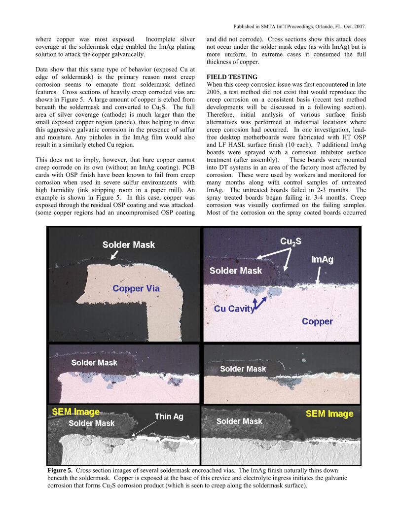
all directions and does not require the board to be powered. Rather it appears that Cu2S is being formed in a layer of moisture on the surface and precipitates out of solution as it forms (since Cu2S is insoluble in water). It is known that sulfur compounds can dissolve readily in water to create a weak sulfuric acid that can in-turn reduce the copper oxide and expose the underlying copper to attack [10]. It requires only about 50% RH to form a thin film of water on a surface. This film is thicker if the surface has hydrophilic properties (polarized to attract water). The study by Xu et. al. [6] tested samples with ISA Class G2 equivalent MFG at 69% RH. Creep corrosion on ImAg surface finish only took place along a fiber which apparently absorbed moisture more readily than the bare laminate that separated the traces (solder mask was not used). Efforts were made to evaluate a few of the environments in which creep corrosion was taking place. Best success was found using copper and silver coupon testing as carried out by a 3rd party [7]. This test involved placing a pure copper and pure silver coupon in several locations in the facility. These were undisturbed for two weeks, at which time they were carefully packaged and shipped back to the 3rd party for measurement of the corrosion product thickness. From this information the ISA class environment was determined and the level of sulfur estimated. Figure 4 shows results of two industrial environments (rubber factory and a clay modeling studio). The advice from this 3rd party was to use the thicker of the Cu and Ag films to determine the ISA class; suggesting these environments were both class G3. The relative humidity level was charted in the rubber factory
and found to range from 55-60% on the day of measurement (not excessive). There are many types of active sulfur compounds that are available to cause corrosion (H2S, elemental sulfur, organic sulfur compounds and mercaptans – used in vulcanizing rubber)[8]. The coupon test does not reveal what type of sulfur is driving the corrosion. Studies have shown that the rate of Cu2S growth increases exponentially with increasing relative humidity while Ag2S grows at the same rate regardless of RH [9]. If the primary corrosion product is copper sulfide, one might wonder why this creep corrosion is predominantly observed on copper with ImAg finish. It seems the electrode potential difference of the two metals plays a significant role (Galvanic driven corrosion). Copper is anodic with respect to silver, and thus in its presence would be attacked much more aggressively in an electrolyte solution (whereas, copper by itself would be attacked significantly slower). This attack of the anode is greatly enhanced when the surface area of the anode is small with respect to the exposed area of the cathode (as one will see is indeed the case in this situation). A similar galvanic corrosion mechanism was implicated as the source of microvoids in solder joints when ImAg surface finish is used [11]. This excellent study revealed that the interaction between silver and copper during the silver plating process caused cavities in the copper (the source of the microvoids upon reflow). These cavities formed under the silver coating and under the edge of the soldermask
Air Quality Results
0
500
1000
1500
2000
2500
WitchitawRm East
WitchitawRm West
Zone 2Office A
Zone 2Office B
ClayStudio A
ClayStudio B
Cor
rosi
on T
hick
ness
(um
)
Copper Film ThicknessSilver Film Thickness
ISA Class GX: SEVEREElectronic/electrical equipment not expected to survive due to corrosive attack.(Cu >= 2000)
ISA Class G3: HARSHHigh probability that corrosive attack will occur. Probable effect on equipment reliability in less than 5 years.(1000 <= Cu < 2000)
ISA Class G2: MODERATEEffects of corrosion measurable and may be a factor in determining equipment reliability. Possible effects in less than 5 years.(300 <= Cu < 1000)
ISA Class G1: MILDCorrosion is not a factor in determining equipment reliability.(Cu < 300)
Company A Company B
Room 1a Room 1b Room 2a Room 2b Room 1a Room 1b
Figure 4. Copper and Silver coupon test results at two industrial environments where creeping corrosion was observed (company A is a rubber manufacturing site and B is a clay modeling studio).
Published in SMTA Int’l Proceedings, Orlando, FL, Oct. 2007.
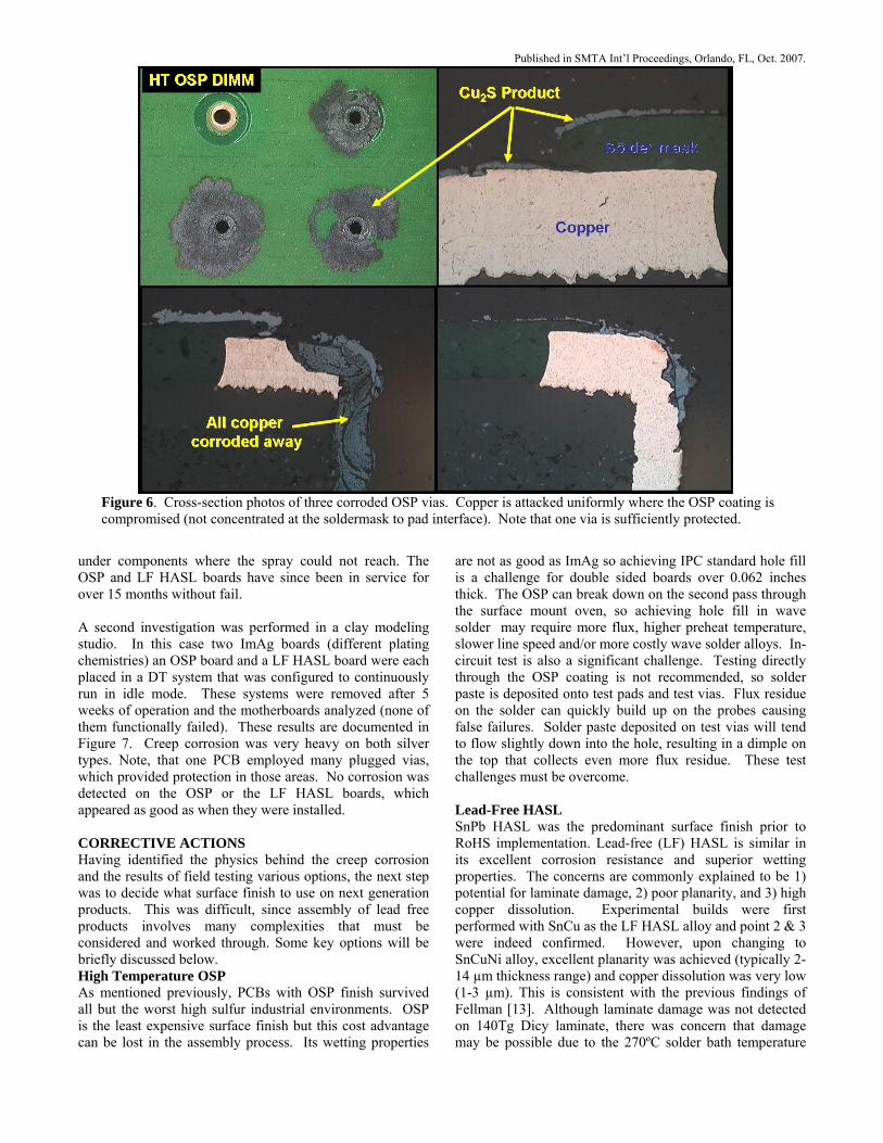
where copper was most exposed. Incomplete silver coverage at the soldermask edge enabled the ImAg plating solution to attack the copper galvanically. Data show that this same type of behavior (exposed Cu at edge of soldermask) is the primary reason most creep corrosion seems to emanate from soldermask defined features. Cross sections of heavily creep corroded vias are shown in Figure 5. A large amount of copper is etched from beneath the soldermask and converted to Cu2S. The full area of silver coverage (cathode) is much larger than the small exposed copper region (anode), thus helping to drive this aggressive galvanic corrosion in the presence of sulfur and moisture. Any pinholes in the ImAg film would also result in a similarly etched Cu region. This does not to imply, however, that bare copper cannot creep corrode on its own (without an ImAg coating). PCB cards with OSP finish have been known to fail from creep corrosion when used in severe sulfur environments with high humidity (ink stripping room in a paper mill). An example is shown in Figure 5. In this case, copper was exposed through the residual OSP coating and was attacked. (some copper regions had an uncompromised OSP coating
and did not corrode). Cross sections show this attack does not occur under the solder mask edge (as with ImAg) but is more uniform. In extreme cases it consumed the full thickness of copper. FIELD TESTING When this creep corrosion issue was first encountered in late 2005, a test method did not exist that would reproduce the creep corrosion on a consistent basis (recent test method developments will be discussed in a following section). Therefore, initial analysis of various surface finish alternatives was performed at industrial locations where creep corrosion had occurred. In one investigation, lead-free desktop motherboards were fabricated with HT OSP and LF HASL surface finish (10 each). 7 additional ImAg boards were sprayed with a corrosion inhibitor surface treatment (after assembly). These boards were mounted into DT systems in an area of the factory most affected by corrosion. These were used by workers and monitored for many months along with control samples of untreated ImAg. The untreated boards failed in 2-3 months. The spray treated boards began failing in 3-4 months. Creep corrosion was visually confirmed on the failing samples. Most of the corrosion on the spray coated boards occurred
Figure 5. Cross section images of several soldermask encroached vias. The ImAg finish naturally thins down beneath the soldermask. Copper is exposed at the base of this crevice and electrolyte ingress initiates the galvanic corrosion that forms Cu2S corrosion product (which is seen to creep along the soldermask surface).
Published in SMTA Int’l Proceedings, Orlando, FL, Oct. 2007.
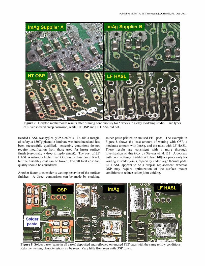
under components where the spray could not reach. The OSP and LF HASL boards have since been in service for over 15 months without fail. A second investigation was performed in a clay modeling studio. In this case two ImAg boards (different plating chemistries) an OSP board and a LF HASL board were each placed in a DT system that was configured to continuously run in idle mode. These systems were removed after 5 weeks of operation and the motherboards analyzed (none of them functionally failed). These results are documented in Figure 7. Creep corrosion was very heavy on both silver types. Note, that one PCB employed many plugged vias, which provided protection in those areas. No corrosion was detected on the OSP or the LF HASL boards, which appeared as good as when they were installed. CORRECTIVE ACTIONS Having identified the physics behind the creep corrosion and the results of field testing various options, the next step was to decide what surface finish to use on next generation products. This was difficult, since assembly of lead free products involves many complexities that must be considered and worked through. Some key options will be briefly discussed below. High Temperature OSP As mentioned previously, PCBs with OSP finish survived all but the worst high sulfur industrial environments. OSP is the least expensive surface finish but this cost advantage can be lost in the assembly process. Its wetting properties
are not as good as ImAg so achieving IPC standard hole fill is a challenge for double sided boards over 0.062 inches thick. The OSP can break down on the second pass through the surface mount oven, so achieving hole fill in wave solder may require more flux, higher preheat temperature, slower line speed and/or more costly wave solder alloys. In-circuit test is also a significant challenge. Testing directly through the OSP coating is not recommended, so solder paste is deposited onto test pads and test vias. Flux residue on the solder can quickly build up on the probes causing false failures. Solder paste deposited on test vias will tend to flow slightly down into the hole, resulting in a dimple on the top that collects even more flux residue. These test challenges must be overcome. Lead-Free HASL SnPb HASL was the predominant surface finish prior to RoHS implementation. Lead-free (LF) HASL is similar in its excellent corrosion resistance and superior wetting properties. The concerns are commonly explained to be 1) potential for laminate damage, 2) poor planarity, and 3) high copper dissolution. Experimental builds were first performed with SnCu as the LF HASL alloy and point 2 & 3 were indeed confirmed. However, upon changing to SnCuNi alloy, excellent planarity was achieved (typically 2-14 µm thickness range) and copper dissolution was very low (1-3 µm). This is consistent with the previous findings of Fellman [13]. Although laminate damage was not detected on 140Tg Dicy laminate, there was concern that damage may be possible due to the 270ºC solder bath temperature
Figure 6. Cross-section photos of three corroded OSP vias. Copper is attacked uniformly where the OSP coating is compromised (not concentrated at the soldermask to pad interface). Note that one via is sufficiently protected.
Published in SMTA Int’l Proceedings, Orlando, FL, Oct. 2007.
(leaded HASL was typically 255-260ºC). To add a margin of safety, a 150Tg phenolic laminate was introduced and has been successfully qualified. Assembly conditions do not require modification from those used for ImAg surface finish (essentially a drop in replacement). The cost of LF HASL is naturally higher than OSP on the bare board level, but the assembly cost can be lower. Overall total cost and quality should be considered. Another factor to consider is wetting behavior of the surface finishes. A direct comparison can be made by studying
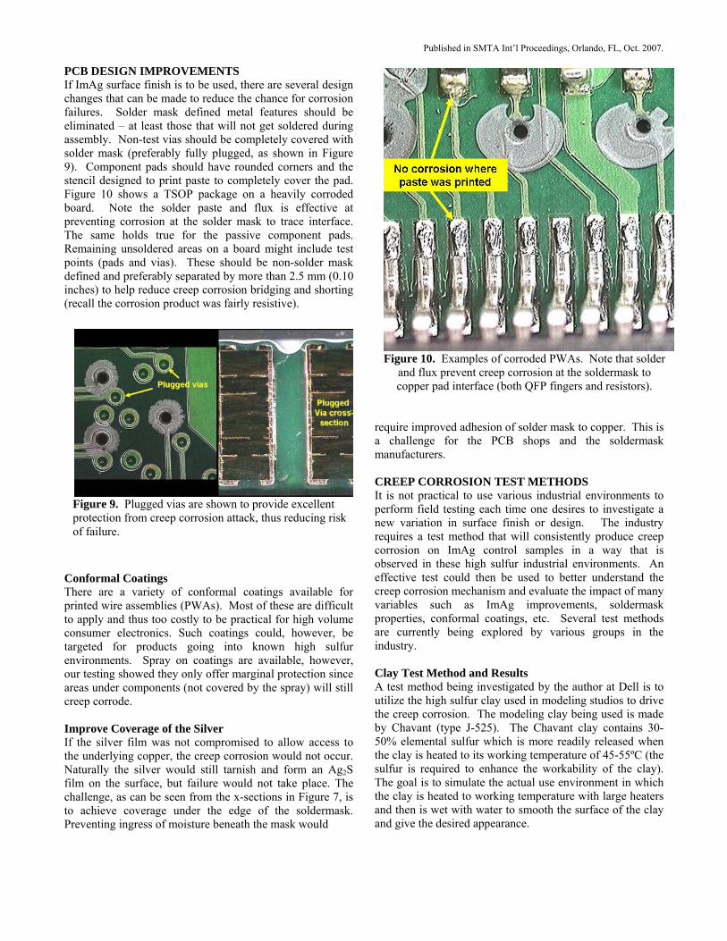
solder paste printed on unused FET pads. The example in Figure 8 shows the least amount of wetting with OSP, a moderate amount with ImAg, and the most with LF HASL. These results are consistent with a more thorough investigation on this topic by Stevens et. al. [12]. A concern with poor wetting (in addition to hole fill) is a propensity for voiding in solder joints, especially under large thermal pads. LF HASL appears to be a drop-in replacement; whereas OSP may require optimization of the surface mount conditions to reduce solder joint voiding.
Figure 7. Desktop motherboard results after running continuously for 5 weeks in a clay modeling studio. Two types of silver showed creep corrosion, while HT OSP and LF HASL did not.
Figure 8. Solder paste (same in all cases) deposited and reflowed on unused FET pads with the same reflow conditions. Relative wetting characteristics can be seen. Very little flow seen with OSP finish.
Published in SMTA Int’l Proceedings, Orlando, FL, Oct. 2007.
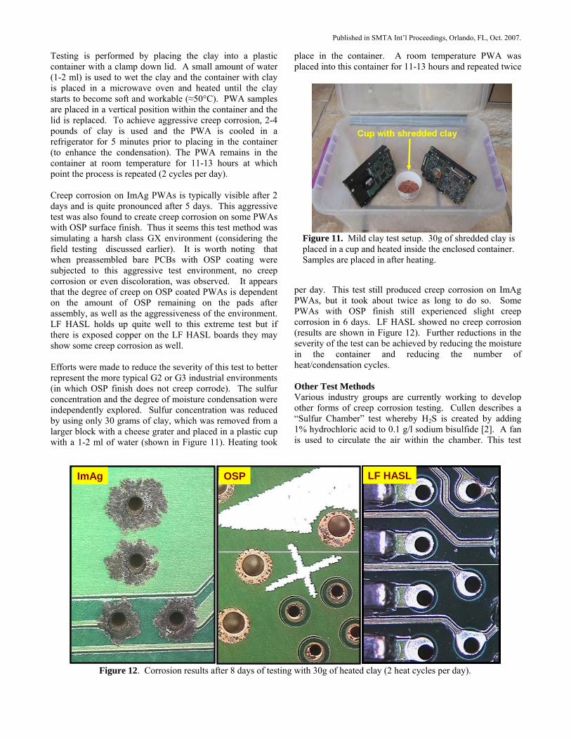
PCB DESIGN IMPROVEMENTS If ImAg surface finish is to be used, there are several design changes that can be made to reduce the chance for corrosion failures. Solder mask defined metal features should be eliminated – at least those that will not get soldered during assembly. Non-test vias should be completely covered with solder mask (preferably fully plugged, as shown in Figure 9). Component pads should have rounded corners and the stencil designed to print paste to completely cover the pad. Figure 10 shows a TSOP package on a heavily corroded board. Note the solder paste and flux is effective at preventing corrosion at the solder mask to trace interface. The same holds true for the passive component pads. Remaining unsoldered areas on a board might include test points (pads and vias). These should be non-solder mask defined and preferably separated by more than 2.5 mm (0.10 inches) to help reduce creep corrosion bridging and shorting (recall the corrosion product was fairly resistive).
Conformal Coatings There are a variety of conformal coatings available for printed wire assemblies (PWAs). Most of these are difficult to apply and thus too costly to be practical for high volume consumer electronics. Such coatings could, however, be targeted for products going into known high sulfur environments. Spray on coatings are available, however, our testing showed they only offer marginal protection since areas under components (not covered by the spray) will still creep corrode. Improve Coverage of the Silver If the silver film was not compromised to allow access to the underlying copper, the creep corrosion would not occur. Naturally the silver would still tarnish and form an Ag2S film on the surface, but failure would not take place. The challenge, as can be seen from the x-sections in Figure 7, is to achieve coverage under the edge of the soldermask. Preventing ingress of moisture beneath the mask would
require improved adhesion of solder mask to copper. This is a challenge for the PCB shops and the soldermask manufacturers. CREEP CORROSION TEST METHODS It is not practical to use various industrial environments to perform field testing each time one desires to investigate a new variation in surface finish or design. The industry requires a test method that will consistently produce creep corrosion on ImAg control samples in a way that is observed in these high sulfur industrial environments. An effective test could then be used to better understand the creep corrosion mechanism and evaluate the impact of many variables such as ImAg improvements, soldermask properties, conformal coatings, etc. Several test methods are currently being explored by various groups in the industry. Clay Test Method and Results A test method being investigated by the author at Dell is to utilize the high sulfur clay used in modeling studios to drive the creep corrosion. The modeling clay being used is made by Chavant (type J-525). The Chavant clay contains 30-50% elemental sulfur which is more readily released when the clay is heated to its working temperature of 45-55ºC (the sulfur is required to enhance the workability of the clay). The goal is to simulate the actual use environment in which the clay is heated to working temperature with large heaters and then is wet with water to smooth the surface of the clay and give the desired appearance.
Figure 10. Examples of corroded PWAs. Note that solder and flux prevent creep corrosion at the soldermask to copper pad interface (both QFP fingers and resistors).
Figure 9. Plugged vias are shown to provide excellent protection from creep corrosion attack, thus reducing risk of failure.
Published in SMTA Int’l Proceedings, Orlando, FL, Oct. 2007.
Testing is performed by placing the clay into a plastic container with a clamp down lid. A small amount of water (1-2 ml) is used to wet the clay and the container with clay is placed in a microwave oven and heated until the clay starts to become soft and workable (≈50°C). PWA samples are placed in a vertical position within the container and the lid is replaced. To achieve aggressive creep corrosion, 2-4 pounds of clay is used and the PWA is cooled in a refrigerator for 5 minutes prior to placing in the container (to enhance the condensation). The PWA remains in the container at room temperature for 11-13 hours at which point the process is repeated (2 cycles per day). Creep corrosion on ImAg PWAs is typically visible after 2 days and is quite pronounced after 5 days. This aggressive test was also found to create creep corrosion on some PWAs with OSP surface finish. Thus it seems this test method was simulating a harsh class GX environment (considering the field testing discussed earlier). It is worth noting that when preassembled bare PCBs with OSP coating were subjected to this aggressive test environment, no creep corrosion or even discoloration, was observed. It appears that the degree of creep on OSP coated PWAs is dependent on the amount of OSP remaining on the pads after assembly, as well as the aggressiveness of the environment. LF HASL holds up quite well to this extreme test but if there is exposed copper on the LF HASL boards they may show some creep corrosion as well. Efforts were made to reduce the severity of this test to better represent the more typical G2 or G3 industrial environments (in which OSP finish does not creep corrode). The sulfur concentration and the degree of moisture condensation were independently explored. Sulfur concentration was reduced by using only 30 grams of clay, which was removed from a larger block with a cheese grater and placed in a plastic cup with a 1-2 ml of water (shown in Figure 11). Heating took
place in the container. A room temperature PWA was placed into this container for 11-13 hours and repeated twice
per day. This test still produced creep corrosion on ImAg PWAs, but it took about twice as long to do so. Some PWAs with OSP finish still experienced slight creep corrosion in 6 days. LF HASL showed no creep corrosion (results are shown in Figure 12). Further reductions in the severity of the test can be achieved by reducing the moisture in the container and reducing the number of heat/condensation cycles. Other Test Methods Various industry groups are currently working to develop other forms of creep corrosion testing. Cullen describes a “Sulfur Chamber” test whereby H2S is created by adding 1% hydrochloric acid to 0.1 g/l sodium bisulfide [2]. A fan is used to circulate the air within the chamber. This test
Figure 11. Mild clay test setup. 30g of shredded clay is placed in a cup and heated inside the enclosed container. Samples are placed in after heating.
ImAg OSP LF HASLImAg OSP LF HASL
Figure 12. Corrosion results after 8 days of testing with 30g of heated clay (2 heat cycles per day).
Published in SMTA Int’l Proceedings, Orlando, FL, Oct. 2007.
produced creep corrosion on many different surface finishes. The same study investigated Class 3 MFG testing in which RH levels over 93% were used to create condensation. Achieving condensation was the only way to generate creep corrosion with MFG, however this can damage the expensive chamber. As previously mentioned, Veale of Rockwell performed MFG testing under electrical bias and electrochemical migration occurred with ImAg finish (different than creep corrosion). A test to replicate the conditions of a rubber factory is being developed by MacDermid and has been successful in producing creep corrosion. Sulfur powder is mixed with mercaptobenzothiazol in a 5:1 ratio and added to water. Samples are hung above the solution and thermal cycling is used to drive condensation. FUTURE WORK ImAg suppliers are actively working on methods to improve the resistance of this finish to creep corrosion. Improvements in solder mask adhesion or photolithography could also be effective in reducing the crevice under the soldermask and should be explored. Dell has discontinued use of ImAg surface finish on PCBs targeted toward industrial environments. Such newly released products utilize a HT OSP or LF HASL surface finish to reduce the chance for failure in high sulfur environments. An industry accepted corrosive environment test method is needed, and should be implemented, to ensure typical industrial environments can deploy lead-free consumer electronic systems without failure. Copper coupon exposure should be used to calibrate the test method to specific ISA class and to user environments. CONCLUSIONS The transition away from SnPb HASL surface finish toward ImAg on high volume electronic products has resulted in creep corrosion when these products are exposed to high sulfur environments under elevated humidity. The creep corrosion product is primarily Cu2S which is produced by galvanic driven attack of the copper beneath the edge of the soldermask. Test methods are being developed to replicate this creep corrosion so the mechanism can be better understood and the effectiveness of corrective actions can be tested prior to their implementation. Testing shows that LF HASL is very resistant to this creep corrosion and HT OSP also appears to be effective in most industrial environments. In the event that ImAg needs to be used, the chance for failure can be reduced through changes in the PCB layout. Design recommendations include: plugging all non-test vias with soldermask, use of non-soldermask defined test vias and pads, spacing these sufficiently apart, and using solder paste to cover all remaining metal features on the PCB. ACKNOWLEDGMENTS Mary Nailos deserves much thanks and credit for preparing the cross section photos and EDX analysis in this paper.
REFERENCES [1] D. Cullen and G. O’Brien, “Underwriters Labs Compliance of ImAg PCB Finish”, OnBoard-Technology, October, 2004. [2] D. Cullen, “Surface Tarnish and Creeping Corrosion on Pb-free Circuit Board Surface Finishes”, IPC Works, 2005. [3] R. Veale, “Reliability of PCB Alternate Surface Finishes in a Harsh Industrial Environments”, SMTA, 2005. [4] P. Mazurkiewicz, “Accelerated Corrosion of PCBs due to High Levels of Reduced Sulfur Gasses in Industrial Environments”, Proc. of the 32nd Int’l Symposium for Testing and Failure Analysis, Nov. 12-16, 2006, Austin, TX. [5] J. Ober, Sulfur Data ]http://minerals.usgs.gov/minerals/pubs/commodity/sulfur/sulfumcs06.pdf [6] C. Xu, D. Flemming, K. Demerkin, G. Derkits, J. Franey, W. Reents, “Corrosion Resistance of PWB Surface Finishes”, Alcatel-Lucent, Apex, 2007. [7] C. Muller, “The Use of Reactivity Monitoring as an Alternative to Direct Gas Monitoring for Environmental Assessment in Cleanrooms”, Purafil Inc., Doraville, GA. [8] ISA 71.04, Environmental Conditions for Process Measurement & Control Systems, 1985. [9] D.W. Rice, P. Peterson, E.B. Rigby, P.Phipps, R Cappell and R. Tremoureux, “Atmospheric Corrosion of Copper and Silver”, J. Electrochem. Soc, Feb. 1981. [10] W.H. Vernon, Trans. Faraday Soc., vol 23, pp 113, 1921, vol 31, pp1668, 1935. [11] M. Mukadam, N. et. al, “Planar Microvoiding in Lead-Free Second Level Interconnect Solder Joints”, Intel, SMTA Proceedings, pg 293, Chicago, 2006. [12] H. Stevens and N. Liyanage, “Is HAL Viable for LF Assemblies”, Circuits Assembly, Oct. 2006. [13] J. Fellman, Printed Circuit Design and Manuf, p. 26, October, 2005. [14] S. Nair, “Malad Malfunction”, The Times of India, Mumbai, April 3, 2007.