Page 1
1
CREEPING LINE SEARCH
PROCEDURE
Garmin Integrated Flight Deck Trainer Version 12.00
AND
Updated G1000 aircraft software
FOR
G1000 MISSION PILOTS
MISSION CO-PILOTS
AND
MISSION OBSERVERS
FOR A
CREEPING LINE SEARCH
MHT 315 deg Radial – 18 nm to 23 nm
8 nm Leg Length – 0.5 nm Track Spacing
Start Northeast Corner
USING
G1000 GARMIN SAR
FROM
Concord Municipal Airport (KCON)
New Hampshire
Page 2
2
G1000 CREEPING LINE SEARCH
MHT VOR 315 RADIAL @ 18nm
MHT 315 radial, 18 to 23 nm, 8 nm legs, 0.5 nm spacing, start NE
A0 = MHT 315 radial @ 18 nm
A1 = A0 045 radial @ 4 nm = CSP A2 = A0 225 radial @ 4 nm
A3 = A2 315 radial @ 5 nm, A4 = A1 315 radial @ 5 nm
The search perimeter defined by above XTK FPL method waypoints.
G1000 GARMIN SAR uses the same A1 waypoint based on the same A0.
Page 3
3
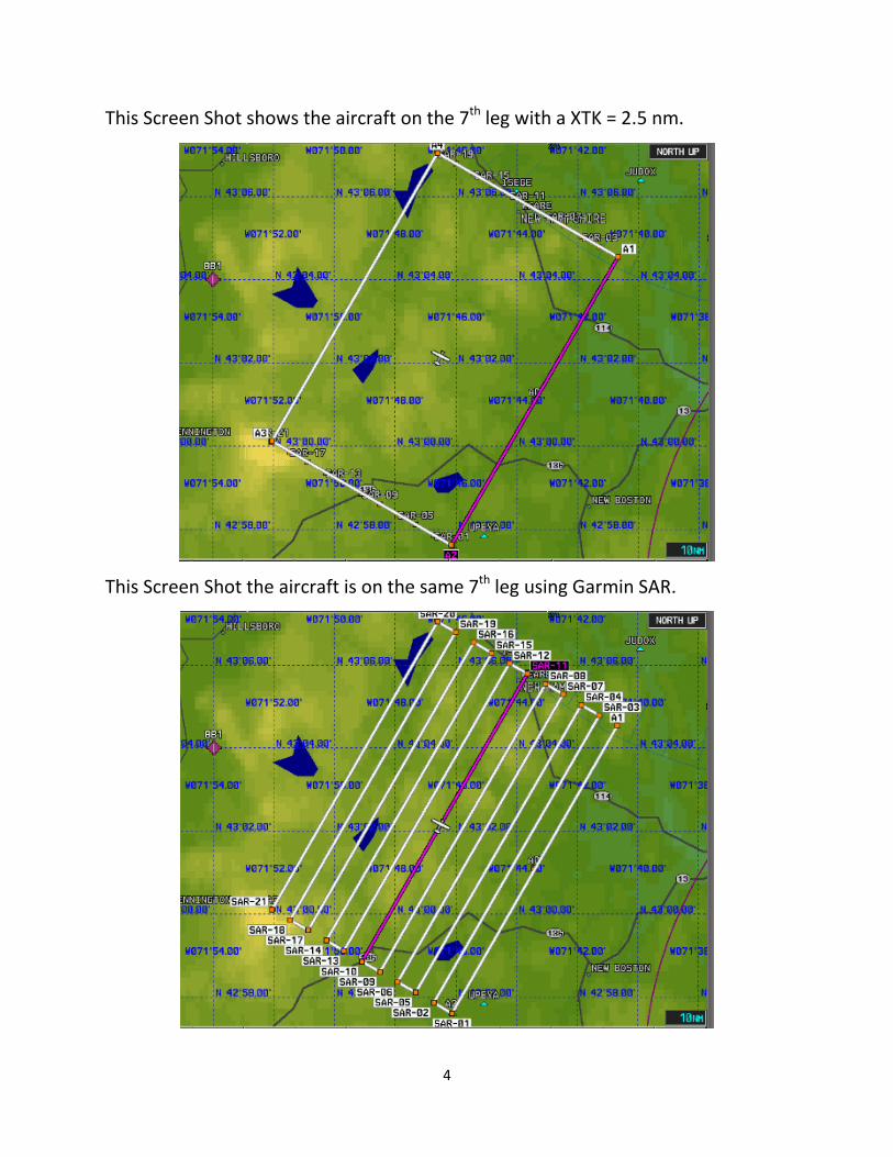
The search area is shown with G1000 MFD Screen Shot using XTK FPL method.
The same search area is shown with G1000 MFD Screen Shot using Garmin SAR.
Page 4
4
This Screen Shot shows the aircraft on the 7th
leg with a XTK = 2.5 nm.
This Screen Shot the aircraft is on the same 7th
leg using Garmin SAR.
Page 5
5
TRAINER:
Press the MENU Key twice, enter KCON in waypoint, and press ENTER key twice.
G1000 Garmin SAR requires the Commence Search Point (CSP) be a waypoint.
For this tutorial the CSP is the User Waypoint A1. Where the A is arbitrary, and
can be any unused letter or letter combination. The number 1 always
corresponds to the CSP. The User Waypoint A0 locates the Creeping Line along
the route line, and used to build User Waypoint A1. The number 0 is used to
locate creeping lines, and to build the user waypoint 1 for both the G1000 Garmin
SAR and the XTK FPL methods and the user waypoint 2 for the XTK FPL method.
Creeping Line Specification:
MHT 315 radial, 18 to 23 nm, 8 nm legs, 0.5 nm spacing, start NE
Build the following user waypoints:
A0 = MHT 315 radial @ 18 nm A1 = A0 045 radial @ 4 nm = CSP
Page 6
6
Press the FPL Key to bring up the Active Flight Plan Panel.
Press the MENU Key to bring up the flight plan options.
Page 7
7
If Garmin SAR is installed, press the ENTER Key. If not, Garmin SAR not available.
Load WAYPOINT: First turn the Inner (Small) FMS Knob counter-clockwise (CCW).
Page 8
8
Then turn the Inner FMS Knob clockwise (CW) until USER drop down list.
Turn the Outer (Large) FMS Knob CW until the waypoint A1 is highlighted.
Page 9
9
OR: Stop on the RECENT drop down list, and highlight the A1 waypoint.
Press the ENTER key twice to load waypoint A1.
Page 10
10
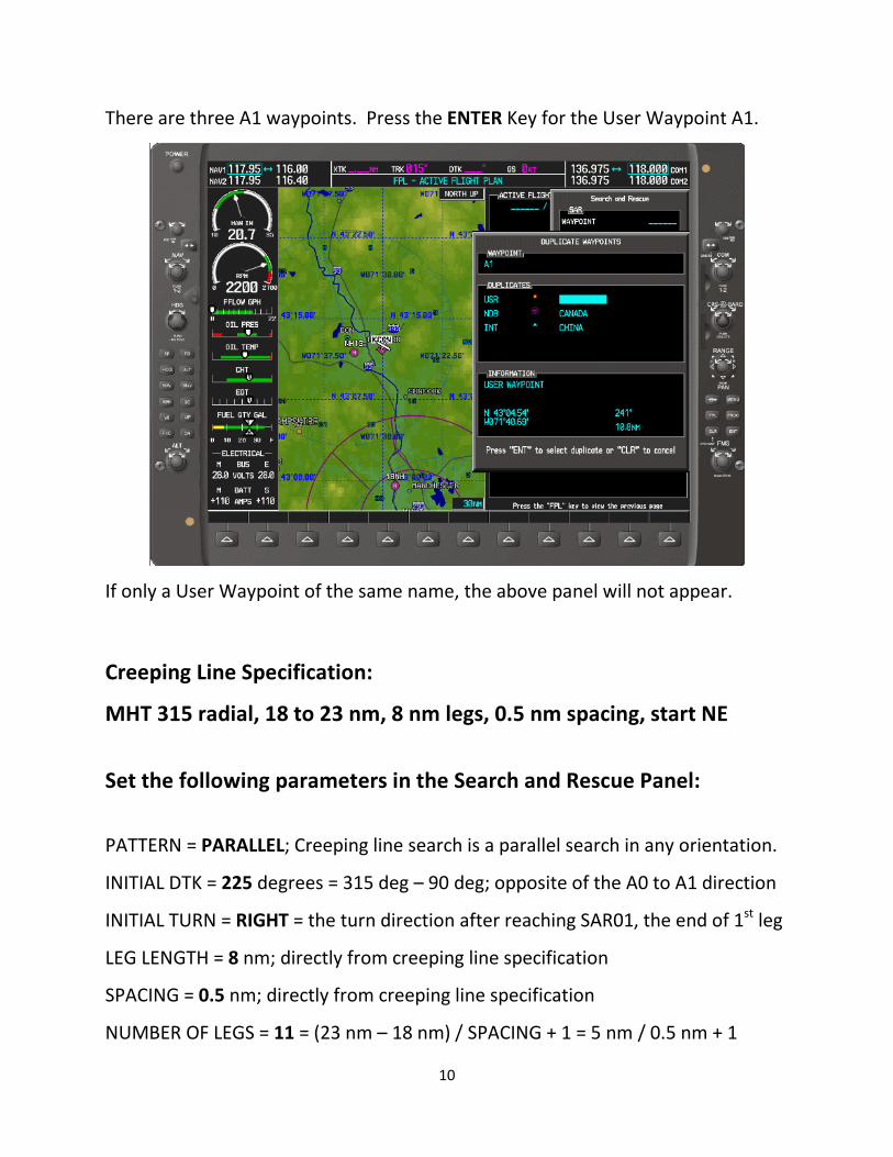
There are three A1 waypoints. Press the ENTER Key for the User Waypoint A1.
If only a User Waypoint of the same name, the above panel will not appear.
Creeping Line Specification:
MHT 315 radial, 18 to 23 nm, 8 nm legs, 0.5 nm spacing, start NE
Set the following parameters in the Search and Rescue Panel:
PATTERN = PARALLEL; Creeping line search is a parallel search in any orientation.
INITIAL DTK = 225 degrees = 315 deg – 90 deg; opposite of the A0 to A1 direction
INITIAL TURN = RIGHT = the turn direction after reaching SAR01, the end of 1st
leg
LEG LENGTH = 8 nm; directly from creeping line specification
SPACING = 0.5 nm; directly from creeping line specification
NUMBER OF LEGS = 11 = (23 nm – 18 nm) / SPACING + 1 = 5 nm / 0.5 nm + 1
Page 11
11
After entering parameters, high light ‘ACTIVATE SAR?’, and press the ENTER Key.
Note the computer generated waypoints, and the DTK. Since the turn at A1 is
very shallow, we will activate the A1 to SAR-01 leg prior to take off. We will
depart the KCON airport on a 270 degree track to intercept the A1 to SAR01 leg
outside of A1. The 270 deg TRK will intercept the SAR-01 leg (DTK=225) at 45 deg.
Page 12
12
Press the Inner FMS Knob to bring up the cursor, and high light SAR-01.
Press the MENU Key to bring up FPL Options, and the Activate Leg is highlighted.
Press the ENTER key to change the active leg from A1 to SAR-01.
Page 13
13
The flight plan leg to SAR-01 is shown active. Note the flight plan leg from KCON
to A1, the CSP. If this leg crossed the search area, we would want to remove it.
Since this leg is no longer necessary, let us remove it anyways.
Using the Outer FMS Knob highlight KCON, and press the CLR Key.
Page 14
14
Press the ENTER Key to confirm removing the KCON to A1 flight plan leg.
The KCON to A1 leg is shown removed. Press the FPL Key to remove the FPL Panel.
Page 15
15
The aircraft is shown at KCON, the A1 to SAR-01 leg active, and the KCON to A1
leg removed. Mission Pilots, Mission Observers, and Mission Co-Pilots must be
able to accomplish all tasks to this point. The balance of this procedure is
required for G1000 Mission Pilots.
We will be taking off of KCON RW 35, and turning to 270 degrees to intercept the
extended A1 to SAR=01 course line before reaching A1, the CSP.
Page 16
16
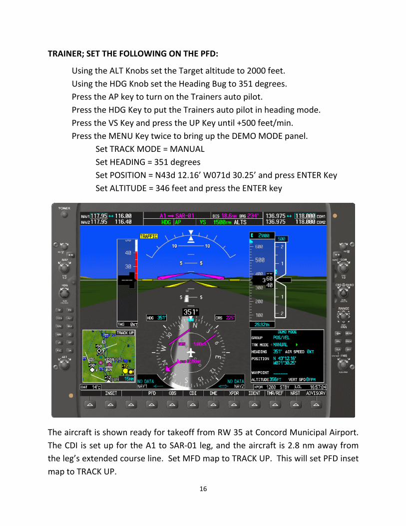
TRAINER; SET THE FOLLOWING ON THE PFD:
Using the ALT Knobs set the Target altitude to 2000 feet.
Using the HDG Knob set the Heading Bug to 351 degrees.
Press the AP key to turn on the Trainers auto pilot.
Press the HDG Key to put the Trainers auto pilot in heading mode.
Press the VS Key and press the UP Key until +500 feet/min.
Press the MENU Key twice to bring up the DEMO MODE panel.
Set TRACK MODE = MANUAL
Set HEADING = 351 degrees
Set POSITION = N43d 12.16’ W071d 30.25’ and press ENTER Key
Set ALTITUDE = 346 feet and press the ENTER key
The aircraft is shown ready for takeoff from RW 35 at Concord Municipal Airport.
The CDI is set up for the A1 to SAR-01 leg, and the aircraft is 2.8 nm away from
the leg’s extended course line. Set MFD map to TRACK UP. This will set PFD inset
map to TRACK UP.
Page 17
17
From the DEMO MODE panel set the AIR SPEED to 100 knots, and press ENTER.
Above, the aircraft is shown on takeoff roll. After reaching 1000 feet, turn HDG
knob to 270 degrees, and arm the Auto Pilot in NAV mode.
Page 18
18
The aircraft is shown having intercepted the extended A1 to SAR-01 course line
Before the DIS gets down to 1 nm, press the FPL key, use Outer FMS Knob to the
next odd waypoint, SAR-03, sync the HDG bug, and press the auto pilot HDG key.
Page 19
19
Turn the HDG Knob to 180 deg for a procedure turn, and press the MENU Key
Press the ENT Key to activate the next search leg.
Page 20
20
When the new XTK is over 1 nm, turn the HDG Knob CW from 180 deg to 360 deg.
After completing the 180 deg turn, arm the autopilot in NAV mode.
Page 21
21
The aircraft is shown on the second search leg with the autopilot in NAV mode.
Before the DIS gets down to 1 nm, press the FPL key, use Outer FMS Knob to the
next odd waypoint, SAR-05, sync the HDG bug, and press the auto pilot HDG key.
Page 22
22
Turn the HDG Knob to 090 deg for a procedure turn, and press the MENU Key
Press the ENT Key to activate the next search leg.
Page 23
23
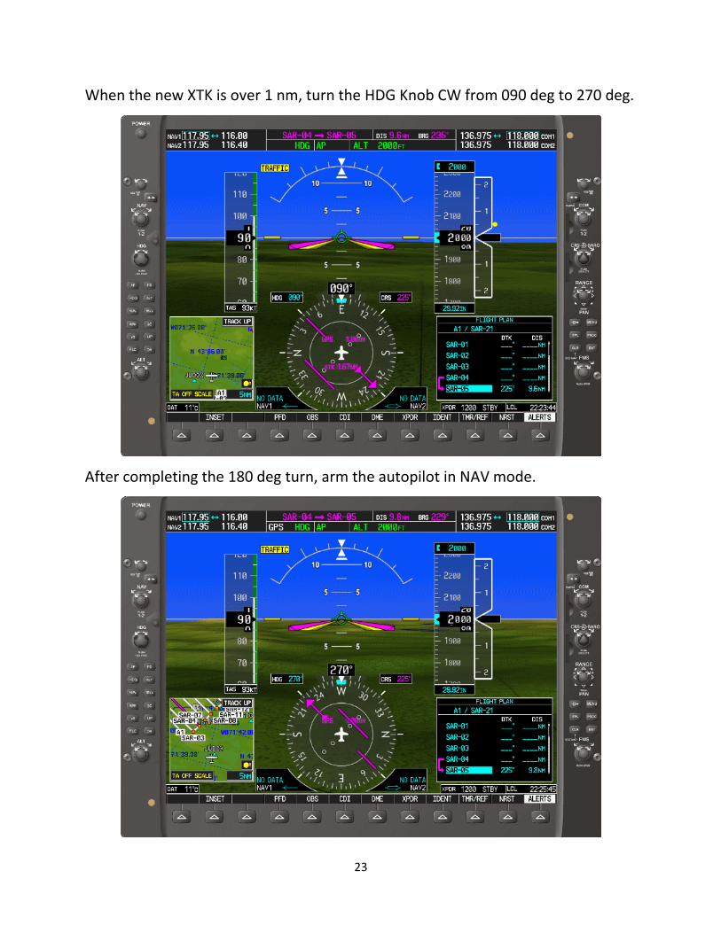
When the new XTK is over 1 nm, turn the HDG Knob CW from 090 deg to 270 deg.
After completing the 180 deg turn, arm the autopilot in NAV mode.
Page 24
24
The aircraft is shown on the third search leg with the autopilot in NAV mode.
TRAINER: Press MENU key twice, highlight AIR SPEED, press the CLR key, and
press the ENTER Key to keep the simulated aircraft from continuing on.
Page 25
25
When 1.0 nm SPACING is chosen, the complete search area can be flown on
autopilot at 90 knots without performing procedure turns at the end of each
search track. When 0.5 nm SPACING is chosen, aircraft with GFC700 autopilots
have CWS (Control Wheel Steering), and the autopilot can be interrupted to
perform 30+ deg bank turns to perform a continuous 180 degree turn in 0.5 nm.
When the CWS button is released the GFC700 autopilot will resume operation. To
perform the same continuous 180 degree turn in 0.5 nm using aircraft equipped
with a KAP140 autopilot, the autopilot will have to be disengaged and reengaged
after the turn is completed. The procedure turn was chosen for this tutorial,
because it is more difficult conceptually, and the G1000 Trainer only does
standard rate turns. The procedure turn is the best way to turn an aircraft in an
effective 180 degree turn in 0.5 nm using standard rate turns at 90 knots.