CROSS CONNECTION CONTROL POLICY “BACKFLOW PREVENTION BY CONTAINMENT” POLICY AND PROCEDURES FOR CLEVELAND UTILITIES WATER and WASTEWATER DIVISION CITY OF CLEVELAND, TENNESSEE PREPARED BY CLEVELAND UTILITIES Revised 11/25/15 2450 Guthrie Drive, NW PO Box 2730 Cleveland, TN 37320
Transcript
CROSS CONNECTION CONTROL POLICY
“BACKFLOW PREVENTION BY CONTAINMENT”
POLICY AND PROCEDURES
FOR CLEVELAND UTILITIES
WATER and WASTEWATER DIVISION CITY OF CLEVELAND, TENNESSEE
PREPARED BY CLEVELAND UTILITIES
Revised 11/25/15
2450 Guthrie Drive, NW
PO Box 2730 Cleveland, TN 37320
2
INDEX SECTION PAGE I. INTRODUCTION 3 II. LOCAL ORDINANCE 3 III. INTENT, PURPOSE, AND CONTROL 3 IV. RESPONSIBILITIES 4 V. IMPLEMENTATION AND ENFORCEMENT 5 VI. INSPECTION OF FACILITIES 5 VII. WATER FROM OTHER SOURCES 6 VIII. SELECTION OF DEVICES 6 IX. APPROVAL OF DEVICES 7 X LOCATION AND INSTALLATION OF DEVICES 7 XI. TESTS, MAINTENANCE, AND REPAIRS 9 XII. CUSTOMER’S DUE PROCESS AND ADDITIONAL INFORMATION 11 XIII. FIRE PROTECTION SYSTEMS 11 APPENDIX A ‐ REFERENCES 13 APPENDIX B ‐ TERMINOLOGY FOR BACKFLOW‐PREVENTION PROGRAM 14 APPENDIX C ‐ TYPICAL CROSS CONNECTION HAZARDS 17 APPENDIX D ‐ REDUCED PRESSURE BACKFLOW PREVENTION DEVICE ‐ INSTALLATION CRITERIA & DRAWINGS 19 APPENDIX E ‐ DOUBLE CHECK AND DOUBLE CHECK DETECTOR ASSEMBLIES – INSTALLATION CRITERIA & DRAWING 20 APPENDIX F ‐ ANNUAL TESTING LETTERS 21 APPENDIX G ‐ REPAIR AND RETEST LETTERS 23 APPENDIX H ‐ CROSS CONNECTION CONTROL ORDINANCE 25 APPENDIX I ‐ TDEC APPROVED BACKFLOW PREVENTION ASSLEMBLIES 29
3
SECTION I. INTRODUCTION
In an alarming number of cases, water is sometimes used in a way that creates a threat to the health and safety of those depending upon the public water supply. Such hazardous water uses are defined as cross‐connections, inter‐connections, by‐passes, and auxiliary intakes by Section 68‐221‐703 of the Tennessee Code Annotated. Section 68‐221‐711(6) of the Tennessee Code Annotated as well as the rules and regulations for public water supplies expressly prohibits the existence of cross‐connections, inter‐connections, by‐passes, and auxiliary intakes. For convenience, all hazards and illegal connections, as defined by Tennessee Law, are referred to simply as cross‐connections. Such illegal connections endanger the health and safety of all those depending upon the public water supply. With such cross‐connections in existence, there is no way to insure that the customer receives safe water at all times. Cleveland Utilities, therefore, recognizes the necessity of maintaining a program to detect and eliminate such hazardous cross‐connections from the distribution system as a necessary means of protecting the quality of water being distributed.
Cleveland Utilities recognizes that it is not reasonable to produce safe water at the treatment plant and then allow cross‐connections to exist which could contaminate the water being distributed to the customers. Cleveland Utilities is dedicated to see that nothing happens to degrade the quality of the water within the distribution system. Cleveland Utilities is also dedicated to supplying safe water to each and every customer under all foreseeable circumstances. The possibility of backflow due to improper use of water within the customer’s premises is especially significant because, when this occurs, the potable water supply may become a transmitter of diseases, toxic materials, and other hazardous substances. The only proper precaution is to eliminate all possible links whereby such contamination may occur. The officials of Cleveland Utilities and the City of Cleveland are committed to take every reasonable precaution possible to see that cross‐connections are not allowed to contaminate the public water supply being distributed to its customers. To do this, it is deemed necessary that a thorough, ongoing program for the detection and elimination of cross‐connections, as well as the prevention of the creation of new cross‐connections, be maintained. The following plan is adopted for administering a program to effectively control cross‐connections.
SECTION II. LOCAL ORDINANCE (OR POLICY)
The City of Cleveland Code; Title 18, Chapter 2 prohibits the existence of cross‐connections within the public water supply. This ordinance to this plan is attached as Appendix F. It is resolved that provisions of this ordinance are to be strictly enforced.
SECTION III. INTENT, PURPOSE, AND CONTROL
1. INTENT: To recognize that all Consumer’s water systems have connections to apparatus, vessels, etc., that could have impurities in varying degrees and, if not properly controlled and contained, could contaminate or pollute both the Consumer’s water system and the Public Potable Water Supply/System. It is also the intent to apply the principle that the type of protection required shall be commensurate with the degree of hazard as determined by Cleveland Utilities.
2. PURPOSE:
(a) To assist the Consumer in protecting his own potable water system against actual or potential backflow and/or backsiphonage of any contamination or pollution by controlling each Cross‐Connection or potential Cross‐Connection within the Consumer’s premises. REFERRED TO AS ‘THE FIRST LINE OF DEFENSE.”
4
(b) To protect the Cleveland Utilities public potable water supply/system against actual or potential
backflow by containing, within a Consumer’s premises, any contamination or pollution that has entered, or may enter, the Consumer’s potable water system through an undiscovered or uncontrolled Cross‐Connection on said premises. REFERRED TO AS “THE SECOND LINE OF DEFENSE.”
(c) To eliminate uncontrolled Cross‐Connections to nonpotable systems as well as uncontrolled
interconnections to any potable water system that is not a part of the Cleveland Utilities, by installing an appropriate Backflow‐Prevention Device(s) to isolate such system(s) from that of Cleveland Utilities.
(d) To establish, coordinate, execute, and maintain a total Cross Connection Control Program.
3. CONTROL:
Requires cooperation between Cleveland Utilities, the City of Cleveland and Bradley County Plumbing Inspection Departments, and the Consumer in the execution of and the adherence to the duties and responsibilities of each as set forth by this Policy and Procedures, and other applicable codes and regulations.
SECTION IV. RESPONSIBILITIES
1. CLEVELAND UTILITIES (PURVEYOR):
Cleveland Utilities is primarily responsible for preventing the contamination and pollution of the Water System’s public potable water supply/system by instituting a program of “Backflow Prevention by Containment.” Such responsibility begins at the point of origin of the potable water supply and includes all of the distribution system, and the service‐connection/water meter to the consumer’s water system. The required consumer‐supplied backflow‐prevention device at the service‐connection/water meter shall provide maximum (Reduced Pressure Zone – RPZ) or minimum (Double Check Valve – DCV) protection as determined by Cleveland Utilities’ Cross Connection Control Coordinator. The required consumer supplied backflow prevention device at the service connection/water meter on all new commercial buildings shall provide maximum (Reduced Pressure Zone – RPZ) protection. In addition, the Coordinator shall exercise reasonable vigilance to ensure that the consumer adheres to this Policy and the Procedures as stated and outlined herein. NOTE: In order for Cleveland Utilities to downgrade the above to minimum protection, a certification of plumbing code compliance, plus annual recertification, will be required.
2. THE PLUMBING INSPECTION DEPARTMENT (INSPECTOR)
The Plumbing Inspection Department is primarily responsible for enforcing the plumbing code to prevent contamination and pollution within the consumer’s water system through a program of “Cross‐Connection Control” requiring that all plumbing outlets terminate through an approved air gap or be controlled by an approved mechanical backflow‐prevention device. Such responsibility begins at the service‐connection/water meter to the premises and extends to the extremities of the consumer’s potable water system.
3. THE CONSUMER (CUSTOMER)
The consumer has the dual responsibility for protecting the potable water in his own system from degradation due to conditions originating on his premises, by complying with the plumbing code, and also for protecting the quality of water in Cleveland Utilities’ system against any potential or actual
5
health hazard(s) generated on or from his premises through uncontrolled cross‐connections, by backflow‐prevention at the service‐connection/water meter. Therefore, after the Coordinator has determined the type of backflow protection that is required at a consumer’s service‐connection/water meter, the consumer is responsible for the cost of procurement, installation, and maintenance of said device.
SECTION V. IMPLEMENTATION AND ENFORCEMENT
1. This policy and these procedures shall be implemented immediately for backflow‐prevention by containment, in conjunction with existing requirements on Backflow‐Prevention by cross‐connection control, for all new potable water and fire protection system installations.
2. Implementation of this policy and these procedures shall also commence immediately on existing
installations. Priority schedules shall be established and evaluations made by Cleveland Utilities for the consumer’s retrofit requirement at the service‐connection/water meter, beginning with those consumers whose premises represent the greatest potential threat to the Public Potable Water Supply/System. Cleveland Utilities, however, shall not be responsible for abatement of cross‐connections which may exist within a consumer’s premises. As a minimum, the evaluation shall consider: the existence of cross‐connections; the nature of the materials handled on the property; the probability of a backflow occurring; the degree of piping system complexity; and the potential for system modification.
3. Enforcement of this policy and these procedures shall be administered by Cleveland Utilities’ Cross
Connection Control Coordinator, in cooperation with Plumbing Inspection, Environmental Health, and Fire Departments of the City of Cleveland and Bradley County.
SECTION VI. INSPECTION OF FACILITIES
1. The consumer, upon request, shall furnish to Cleveland Utilities, any pertinent information regarding
the consumer’s water system on such premises where backflow and/or backsiphonage are deemed possible through uncontrolled plumbing connections and/or cross‐connections.
2. Nothing herein shall relieve the consumer of the responsibility for conducting or causing to be
conducted periodic surveys of water‐use practices on his premises to determine whether there are actual or potential uncontrolled cross‐connections within the consumer’s water system through which contaminants or pollutants could flow back into his own or Cleveland Utilities’ Public Potable Water Supply/System. If the premises are classified, restricted, or high security with no admittance, maximum (RPZ) protection at the service‐connection/water meter is required.
3. Facilities considered to pose an actual or potential contamination and/or pollution threat to the Water
System’s Public Potable Water Supply/System will be subject to inspection by an authorized representative(s) of Cleveland Utilities Water System and, when deemed necessary, in accompaniment with a representative(s) from the plumbing inspection, health, and/or fire departments. Inspections will focus on plumbing outlets and potential contaminating or polluting substances within a facility. Inspections will be scheduled at a time mutually agreeable with the consumer’s representative and the Cleveland Utilities’ representative(s). Using information gathered, the Water System’s representative will determine the degree of potential backflow hazard and specify the type of backflow protection required at the consumer’s service‐connection/water meter.
4. If, upon inspection, a facility is found not to be in full compliance with the plumbing code, maximum
protection will be required. If the owner brings the facility up to full code compliance within a ninety (90) day period, minimum protection will be allowed at the service‐connection/water meter provided potential hazards within the premises are low.
6
5. While in the course of a routine inspection or special investigation, the Inspector(s) discovers a
condition of imminent or actual high hazard system contamination; Cleveland Utilities will immediately discontinue service to the facility. Service will not be restored until the hazardous condition has been corrected and reinspected.
6. In the event of accidental contamination or pollution of the Public Potable Water Supply/System, the
consumer, if he is so aware, shall immediately notify Cleveland Utilities so that appropriate measures may be taken to contain and isolate the contaminant or pollutant.
NOTE: Cost liabilities are the consumer’s responsibility.
7. After reasonable notice to the consumer, of a violation of this policy and/or procedure existing on the premises, water service will be discontinued, and any other such precautionary measures taken that are deemed necessary to protect the quality of the water in Cleveland Utilities. Water service shall not be restored until the danger has been eliminated in compliance with the provisions of this procedure.
SECTION VII. WATER FROM OTHER SOURCES
1. When any premises are served by Cleveland Utilities, and the owner of said premises continues to have a well or any other source of water, it shall be in violation of these procedures for the plumbing on said premises to be installed or so interconnected that water in the Cleveland Utilities Water System and the private water supply can, in any way, become intermingled.
2. Upon discovery of an uncontrolled interconnection on any premises being furnished water through
Cleveland Utilities’ water system, as in Item (1) above, the owner of said premises shall be notified that the interconnection must be removed or controlled by a backflow‐prevention device within thirty (30) days, and that failure to remove or correct the interconnection will result in removal of the meter. It the correction is not made within the thirty (30) day period, the meter will be removed and will not be reinstalled until the maximum‐type backflow protection is installed at the service‐connection/water meter, and the owner has paid for all associated costs.
3. Booster pumps installed on the service line to or within any premises shall be equipped with a low‐
pressure cut‐off device designed to shut off the booster pump when the pressure in the service line on the suction side of the pump drops to 20 PSI or below. It shall be the duty of the water consumer to maintain the low‐pressure cut‐off device in proper working order at all times.
NOTE: Consumer shall assume all liabilities.
SECTION VIII. SELECTION OF DEVICES
1. Vacuum breakers and backflow preventers shall be selected on the basis of the impurities involved and the type of cross‐connection. The impurities shall be classified as contaminants (hazardous) and pollutants (nonhazardous); the type of cross‐connection by whether it is nonpressure or pressure as follows:
(a) CROSS‐CONNECTION, NONPRESSURE TYPE: This type of connection, when not protected by a
minimum air gap, shall be protected by an appropriate vacuum breaker or an appropriate backflow preventer (BFP).
(b) CROSS‐CONNECTION, PRESSURE TYPE: This type of connection shall be protected by an
appropriate RPZ only. CAUTION: A pressure vacuum breaker shall not be used alone on a pressure‐type cross‐connection.
7
NOTE: Because an irrigation system serves an environment that is open to atmosphere, it would not be classified as a pressure‐type cross‐connection. However, due to the special nature of the installation, minimum protection against backflow shall include a double check valve backflow preventer. If chemicals are injected into the system or the system stays pressurized, maximum protection shall include a reduced pressure zone backflow preventer.
2. Vacuum breakers shall be corrosion resistant. Other backflow‐prevention devices, including accessories, components, and fittings in sizes 2 inch and smaller shall be bronze with threaded connections. Sizes 2 ½ inch and larger shall be bronze or fused epoxy‐coated iron inside and out, with flanged connections.
3. Each device shall have a brass identification tag, securely attached with corrosion‐resistant mechanical fasteners, and include the manufacturer’s name, serial number, and maximum working pressure and temperature.
SECTION IX. APPROVAL OF DEVICES All backflow‐prevention devices shall be approved in accordance with the applicable standard of the American Society of Sanitary Engineering, the National Standards Institute, the American Water Works Association, and the University of Southern California Foundation for Cross‐Connection Control and Hydraulic Research.
SECTION X. LOCATION AND INSTALLATION OF DEVICES
1. Location of all backflow‐prevention devices shall be in an area that provides a safe working environment for testing and maintenance. This area shall be readily accessible and free from extreme cold, heat, and/or electrical hazards.
2. Installation of all backflow‐prevention devices shall be in accordance with Cleveland Utilities’ CCC specifications and other applicable codes and regulations. Installations for containment shall be by a duly licensed plumbing, mechanical, and/or utility contractor.
(a) When a dual or double check valve backflow preventer is used in the containment concept, it
shall be installed at or as close to the service‐connection/water meter as practical, in an approved below ground enclosure. See Appendix F.
(b) When a reduced pressure zone backflow preventer is installed at the sevice‐connection, it shall
be above ground in a structure that is protected from freezing. The enclosure shall not cause a confined space. In lieu of the above ground installation at the service‐connection/water meter, and at the owner’s request, the water purveyor and the plumbing official may allow the RPZ to be installed immediately inside the building, in which case the device would remain under the jurisdiction of Cleveland Utilities and subject to inspections, and testing by its authorized representative. See Appendix D.
NOTE: When a backflow preventer is installed in a service pipe inside a structure on any premises for the purpose of containing said premises, it shall be unlawful to tap into such service pipe between the BFP and the service‐connection/water meter. Any branch connection(s) on an existing service pipe shall be permanently disconnected or equipped with a backflow preventer(s) commensurate with the degree(s) of hazard.
3. Facilities that must have continuous uninterrupted water supply shall install backflow‐prevention devices in parallel for testing and maintenance purposed. In no case shall a bypass arrangement be installed or maintained unless also equipped with an approved backflow‐prevention device.
8
4. Vacuum breakers and backflow preventers equipped with atmospheric vents or with relief openings,
shall be so installed and so located as to prevent any vent or any relief opening from being submerged. They shall be installed in the position as recommended by the manufacturer, and as prescribed in the following:
(a) VACUUM BREAKER, ATMOSPHERIC TYPE (AVB): This device shall be at least 6 inches above the
highest outlet or the overflow level on the nonpotable system. It shall be installed downstream of the last shut‐off valve.
(b) VACUUM BREAKER, PRESSURE TYPE (PVB): This device shall be installed at least 12 inches above
the highest outlet or the overflow level on the nonpotable system. It may be installed upstream of the last shut‐off valve.
(c) VACUUM BREAKER, HOSE TYPE (HVB): This device shall be installed directly on the hose threads,
if not an integral part of the valve. It may not be subjected to continuous pressure, static or flowing. Nor shall it be attached to a freezeless‐ type hydrant unless it is a model specifically designed for this service.
CAUTION: Freezeless hydrants require manual winterization except those models with integral vacuum breaker and automatic drainage feature.
(d) BACKFLOW PREVENTER, DUAL CHECK (DUC): This device shall not be buried in earth but may be installed below ground as in a meter box. A positive shut‐off valve and union shall be near the inlet and outlet sides.
EXCEPTION: When the device is attached directly to a meter, and both are intended to be removed as a unit, one union is required on the device. Except when a meter or other device with bronze strainer, integral or attached, is immediately upstream of the backflow preventer, a bronze strainer shall be provided between the inlet shut‐off and the device.
(e) BACKFLOW PREVENTER, DOUBLE CHECK VALVE (DCV) and DOUBLE CHECK DETECTOR CHECK VALVE (DCDCV): This device can be installed in a vault below ground level. Above ground level installations are also acceptable and must be in an approved enclosure. A full port ball valve in sizes through 2”, and a ball or resilient‐seated gate valve in sizes above 2”, shall be near the inlet and outlet sides of the device. The device shall be provided with three ball valve test cocks and a fourth test cock shall be provided on the upstream side of the inlet shut‐off valve. No intervening connection(s) shall be between the shut‐off valves and the backflow preventer except when a meter or other device with bronze strainer, integral, or attached, is immediately upstream of the backflow preventer.
(f) BACKFLOW PREVENTER WITH INTERMEDIATE ATMOSPHERIC VENT (IAV): This device shall not
be installed below ground. Where relief valve discharge could cause water damage, it shall be piped via an air gap, or a funnel, at the vent/relief port to a floor drain or other approved location. A positive shut‐off valve and union shall be near the inlet and outlet sides of the device. A strainer shall be included as in Paragraph (d) above.
(g) BACKFLOW PREVENTER, REDUCED PRESSURE ZONE (RPZ): This device shall not be installed
below ground. Where relief valve discharge could cause water damage, it shall be piped via an air gap, or a funnel, at the vent/relief port to a floor drain or other approved location. Positive shut‐off valves, test cocks, and strainer are to be provided as in Paragraph (e) above. No intervening branch connection(s) shall be between the shut‐offs and the backflow preventer.
9
NOTE: When a reduced pressure zone device is installed in a line subject to periodic no‐flow conditions, and supply pressure subject to fluctuations, an auxiliary directional check with soft discs capable of functioning in any position of the RPZ may be installed. The device shall be placed between the inlet shut‐off valve and the RPZ head to lock the supply pressure in, and prevent unnecessary discharges through the vent/relief port. Make‐up lines to chilled water systems and hydronic heating systems are examples of installations where a drop in supply pressure may occur during no‐flow conditions. When a water pressure reducing valve is required in the same line with the RPZ device, it is usually possible to locate the reducing valve upstream of the device and take advantage of the check valve effect of the reducing valve. In such case, the auxiliary directional check would not be required.
*****SPECIAL CAUTION*****
THERMAL EXPANSION – When water is heated and stored in a distribution system or a branch of the system that has been closed by the installation of a backflow‐prevention device or any other checking device, an approved auxiliary relief valve, or expansion chamber shall be installed to limit thermal expansion of the water being heated to not more than 80 PSI no‐flow pressure at any fixture on the system.
SECTION XI. TESTS, MAINTENANCE, AND REPAIRS
1. All backflow‐prevention devices, both existing and new, and all parts thereof, shall be maintained in a safe condition and in good working order.
2. The consumer shall be responsible for the cost of testing, maintenance, and repair of all backflow‐prevention devices downstream of the service‐connection/water meter within the premises and on his own private system.
3. The consumer is responsible for backsiphoned material or contamination and/or pollution through backflow and, if contamination or pollution of Cleveland Utilities’ Public Potable Water Supply/System occurs through an illegal cross‐connection and/or an improperly installed, maintained, or repaired device, or a device that has been bypassed, he is liable for all associated costs of clean‐up of the Public Potable Water Supply/System.
4. Tests, maintenance, and repairs are to be made in accordance with the following schedule or more
frequently where inspections indicate a need or are specified in the manufacturer’s instructions:
(a) FIXED AIR GAP SEPARATIONS – shall be inspected at the time of installation and at least annually thereafter.
(b) PRESSURE VACUUM BREAKERS – shall be inspected and tested at the time of installation and at
least annually thereafter.
(c) DUAL CHECK VALVES – shall be inspected and tested at time of installation and at least annually thereafter.
(d) DOUBLE CHECK VALVE BACKFLOW PREVENTERS – shall be inspected and tested at time of
installation and at least annually thereafter.
(e) REDUCED PRESSURE ZONE BACKFLOW PREVENTERS – shall be inspected and tested at time of installation and at least annually thereafter.
10
(f) SYNTHETIC COMPONENTS WITHIN A DEVICE – shall be replaced every five (5) years or sooner if required.
5. All backflow‐prevention devices will be tested according to the Tennessee Backflow Prevention
Association’s testing procedures.
6. Testing must be performed by an individual(s) who is certified by the Tennessee Department of Environment and Certification and trained to understand the design and intended operation of the device(s) being tested, and has proved his competency to Cleveland Utilities. All certified testers shall submit a copy of their current certification to Cleveland Utilities and are required to maintain their certification with the Tennessee Department of Environment and Conservation. No test results will be accepted by Cleveland Utilities without a copy of the current certification on file.
7. Testers must use kits that have been certified annually by a lab approved (or certified) by the
manufacturer of the test kit. A copy of the test kit certification shall be submitted to Cleveland Utilities annually following the kit certification. No test results will be accepted by Cleveland Utilities without a copy of the current kit certification on file.
8. A test and maintenance log for each RPZ, DCV, and PVB device shall be maintained by the consumer. Following each test or repair, a report must be sent to Cleveland Utilities, and include the following information:
(a) Date of installation and location; (b) Manufacturer’s name and serial number;
(c) Date of each test or visual inspection;
(d) Name of authorized person performing test;
(e) Test results;
(f) Description of repairs or servicing required;
(g) Date repairs completed.
9. Testing shall be performed and all results shall be submitted to Cleveland Utilities within 30 calendar
days of being requested by Cleveland Utilities. If the test is not been performed within 30 calendar days following the request, a certified letter will be sent to the customer notifying them that if testing is not performed within the next 30 calendar days the President/CEO may be notified to begin termination procedures. The customer will be given 10 calendar days to comply. If the customer completes the testing prior to the deadline, termination procedures will be halted.
10. All backflow‐prevention devices and logs shall be subject to periodic inspection by Cleveland Utilities’ Cross Connection Control Coordinator. If a device is found to be inoperative or malfunctioning, the consumer will be given 30 calendar days to complete corrections required by the Coordinator. With the exception of cases involving actual or imminent system contamination, the time allotted for corrections will be determined by the degree of potential hazard posed to the Public Potable Water Supply System.
11. If the corrective measures have not been taken within 30 calendar days, then a certified letter will be sent to the consumer notifying them that if corrections are not taken within the next 30 days, the General Manager will be notified and recommended to begin termination of water service procedures.
11
The consumer will be given 10 calendar days to comply. If the consumer completes the corrections prior to the deadline, termination procedures will be halted.
SECTION XII. CUSTOMER’S DUE PROCESS AND ADDITIONAL INFORMATION
Any decision to terminate a customer’s service may be appealed per the Customer’s Due Process Procedure as described in the Cleveland Utilities Schedule of Rules and Regulations. Any questions regarding this policy and/or these procedures may be directed to Cleveland Utilities’ Cross Connection Control Coordinator.
SECTION XIII. FIRE PROTECTION SYSTEMS
1. For purpose of backflow‐prevention, fire protection systems shall be classified as sprinkler, standpipe, or combined. Sprinkler systems shall be further classified as follows:
Class 1 – Directly supplied from public water mains only; no pumps, tanks, or reservoirs; no physical connection from other water supplies; no antifreeze or additives of any kind; all sprinkler drains discharging to atmosphere, dry wells, or other safe outlets. Class 2 – Directly supplied from public water mains, same as Class 1, except that authorization has been obtained for a booster pump to be installed in the supply line. NOTE: Requires special approval and permit from Cleveland Utilities. Class 3 – Directly supplied from public water mains, same as Class 1, plus one or more of the following: elevated storage tanks or pressure tanks; fire pumps taking suction from above ground covered reservoirs or tanks. All storage facilities shall be filled from the potable water supply and maintained in a potable condition. Class 4 – Directly supplied from public water mains, similar to Classes 1 and 2, and with an auxiliary water supply on or available to the premises; or an auxiliary water supply located within approximately 1, 700 feet of the pumped connection. Class 5 – Directly supplied from public water mains, and interconnected with auxiliary supplies, such as: pumps taking suction from reservoirs exposed to contamination, or rivers and ponds; driven wells; mills or other industrial water systems; or where antifreeze or other additives are used. Class 6 – Directly supplied from public water mains only, with or without gravity storage or pump suction tanks, and interconnected with industrial systems.
2. Standpipe systems shall be further classified as nonhazardous (impurities equal Class 3 or lower sprinklers), and hazardous (impurities equal Class 4 or higher sprinklers).
3. Fire Protection systems shall be contained from the Public Potable Water Supply/System by backflow‐
prevention devices that have approvals as required under Section VII of this procedure and classified or listed by the Underwriters Laboratories and Factory Mutual Insurance, as follows:
Class 1, 2, and 3 SPRINKLER SYSTEMS and NONHAZARDOUS STANDPIPE SYSTEMS: shall be contained by the installation of double check detector check backflow preventer. Class 4, 5, and 6 SPRINKLER SYSTEMS and HAZARDOUS STANDPIPE SYSTEMS: shall be contained by reduced pressure backflow preventers.
4. Combined sprinkler and standpipe systems shall be contained from the Public Water mains by procedures applicable to the component that requires the higher degree of protection.
12
5. The purpose of certain checking devices used, or likely to be used, with fire protection systems is outlined below to call attention to those that are approved for backflow‐prevention and those that are not:
(a) DIRECTIONAL CHECK – to provide directional flow only. This is not a backflow‐prevention device. (b) ALARM CHECK – to signal an alarm; to summon the fire department, etc., when a sprinkler head
flows water; and on wet‐pipe systems, to provide directional flow.
(c) DETECTOR CHECK – to detect unauthorized use of water for other than fire service; to detect leaks in fire protection systems; and with by‐pass check, to provide directional flow.
(d) DOUBLE CHECK – to prevent backflow of polluted water from fire protection systems into the potable water system; and to provide directional flow.
(e) DOUBLE DETECTOR CHECK – to prevent backflow of polluted water from fire protection systems
into a potable water system; to detect unauthorized use of water; to detect leaks in fire protection systems; and to provide directional flow.
(f) REDUCED PRESSURE ZONE CHECK – to prevent backflow of contaminated water from fire
protection systems into the potable water system; and to provide directional flow.
(g) REDUCED PRESSURE DETECTOR CHECK – to prevent backflow of contaminated water from fire protection systems into the potable water system; to detect unauthorized use of water; to detect leaks in the fire protection system; and to provide directional flow.
6. Single detector checks that are used on standpipes, Class 3 or higher sprinklers, or combined systems
may not be considered as a component part of a DDC backflow preventer unless approved by the Coordinator having jurisdiction. Specifically, the addition of a second detector check to one of these devices may not be substituted for a double detector check, that is approved for backflow‐prevention, unless such addition results in a device identical to that furnished by the manufacturer, and the resulting assembly qualifies for the appropriate backflow preventer label.
7. It is intended that an approved double check detector check backflow preventer be in lieu of; not in
addition to, the two checking devices already required in the supply to Class 1 and 2 sprinklers, or the double check detector check valve BFP already required on Class 3 sprinklers, nonhazardous standpipes, and combined systems; or that an approved reduced pressure detector check be substituted for the RPZ already required on hazardous systems. In such cases the net additional device(s) intended are the detector meter and backflow preventer in the bypass.
8. The two shut‐off valves required for periodic testing of a backflow preventer, whether supplied by the
backflow preventer manufacturer or the fire protection contractor, shall be listed for fire protection service by Underwriters Laboratories and Factory Mutual Insurance, and the inlet valve shall include an approved test cock on the upstream side.
9. To distinguish between systems used exclusively for fire service, and those used for both fire service
and potable water service, the following terminology shall apply:
(a) COMBINED SYSTEM – bulks and expresses risers that supply both standpipe and sprinkler systems. This system is for fire service only.
(b) COMBINATION SYSTEM – standpipe risers that supply both fire service and potable water
service. This system is relatively new.
13
APPENDIX A
REFERENCES a) Manuals
1. “Recommended practice for backflow prevention and Cross‐Connection Control.” AWWA Manual M14, 1966, 1990
2. “Manual of Cross‐Connection Control.” Foundation for Cross‐Connection Control and Hydraulic Research,
University of Southern California, 1985.
3. “Cross‐Connection Control Manual.” Division of Sanitary Engineering, Tennessee Dept. of Public Health, 1985.
4. “Cross‐Connection Control Manual.” U.S. Environmental Protection Agency, 1985.
b) Device Standards
1. AWWA c506‐78‐, “AWWA Standard for Backflow Prevention Device, Reduced Pressure Principle and Double Check Valve Types.” 1978.
2. ASSE Standard #1001, “Pipe Applied Atmospheric Type Vacuum Breakers.” 1980.
3. ASSE Standard #1011, “Hose Connection Vacuum Breakers.” 1976.
5. ASSE Standard #1015, Double Check Valve Type Back Pressure Backflow Preventers.” 1980.
c) Regulations, Laws, and Codes
1. Public Law 93‐523, “Safe Drinking Water Act.” Dec. 16, 1974. 2. Rules of the Department of Environmental Regulation, Chapter 17‐22, “Water Supplies.” Nov. 9, 1977.
3. Southern Building Code Congress International, Standard Plumbing Code, 1979, (with Amendments).
4. The National Fire Protection Association, Installation of Sprinkler System, NFPA No. 13.
Abbreviation: AWWA – American Water Works Association ASSE – American Society of Sanitary Engineering USC – University of Southern California
14
APPENDIX B
TERMINOLOGY FOR
BACKFLOW‐PREVENTION PROGRAM BACKFLOW– a reverse flow in a water system from the normal or intended direction. BACKFLOW PREVENTER (BFP) – a device designed to prevent reverse flow in a water system. The term should normally be used where backpressure‐type backflow is implied. BACKFLOW PREVENTER, DOUBLE CHECK VALVE (DCV) – a backpressure‐type backflow‐prevention device designed for continuous or intermittent pressure, including backpressure, where pollutants are involved. BACKFLOW PREVENTER, DOUBLE DETECTOR CHECK (DDC) – a backpressure‐type backflow‐prevention device designed to serve also as a detector check on fire protection systems where pollutants are involved. It includes a line‐size approved double check valve backflow preventer with a metered bypass, into which has also been incorporated an approved double check valve backflow preventer. BACKFLOW PREVENTER, DUAL CHECK (DUC) – a backpressure‐type backflow‐prevention device designed especially for containing water systems to residences, mobile homes, etc., as the "second line of defense," and for isolating residential lawn sprinkler systems, etc., where pollutants only are involved. BACKFLOW PREVENTER WITH INTERMEDIATE ATMOSPHERIC VENT (IAV) – a backpressure and backsiphonage‐type backflow‐prevention device designed to operate under continuous pressure, including backpressure, where low‐degree contaminants are involved. BACKFLOW PREVENTER, REDUCED PRESSURE ZONE (RPZ) – a backpressure and backsiphonage‐type backflow‐prevention device designed to operate under continuous pressure, including backpressure, where contaminants are involved. BACKFLOW PREVENTER, REDUCED PRESSURE DETECTOR CHECK (RPDC) – a backpressure and backsiphonage‐type backflow‐prevention device designed to serve also as a detector check on fire protection systems where contaminants are involved. It includes a line‐size reduced pressure zone backflow preventer with a metered bypass, into which has also been incorporated an approved reduced pressure zone backflow preventer. BACKFLOW‐PREVENTION – a program, an ordinance, a code, a policy; designed to discover, to eliminate, to prevent all unauthorized and uncontrolled backflow and cross‐connections. BACKFLOW‐PREVENTION BY CROSS‐CONNECTION CONTROL – the installation of a backflow‐prevention device at each cross‐connection on a premises to protect both the premises and the Public Water Supply main ("The First Line of Defense"). BACKFLOW‐PREVENTION BY CONTAINMENT – the installation of a backflow preventer at the service‐connection to the premises to protect the Public Water Supply Main only ("The Second Line of Defense"). BACKPRESSURE – an increase in pressure in a Consumer's water system, or a branch of the systems, above that at the service‐connection. It is generally caused by pumps, thermal expansion, or reasons other than a reduction or loss of the incoming pressure. Backpressure is generally more evident in a closed water system.
15
BACKSIPHONAGE – a reverse flow in a water system caused by a negative pressure in the incoming pipe, when the point of use is at atmospheric pressure. Backsiphonage is generally more evident in an open water system. BACKSIPHONAGE PREVENTER – a device designed to prevent reverse flow in a water system. The term should be used only where a negative supply pressure is implied. CERTIFIED TESTER – a person qualified to test and repair backflow‐prevention and cross‐connection control devices; and who has proved his competency to the Cleveland Utilities. CLOSED WATER SYSTEM – one with a checking device installed in the service pipe. A check valve, backflow preventer, or pressure reducing valve would create a closed system. CONSUMER'S WATER SYSTEM – all potable water piping, valves, fittings, and appurtenances on the premise side of the service‐connection. CONTAMINANT – any substance that, if introduced into the potable water system, could create a health hazard. CROSS‐CONNECTION – a physical connection or arrangement between two otherwise separate piping systems; one of which contains potable water, the other a nonpotable fluid, or water or unknown quality, where there could be backflow into the potable system unless it is protected by an appropriate backflow‐prevention device. CROSS‐CONNECTION, NONPRESSURE TYPE – a low‐inlet installation where a potable water pipe is connected or extended below the overflow rim of a receptacle, or an environment, that contain a nonpotable fluid, and is at atmospheric pressure. CROSS‐CONNECTION, PRESSURE TYPE – an installation where a potable water pipe is connected to a closed vessel, or a piping system, that contains nonpotable fluid, and is above atmospheric pressure. HAZARD, DEGREE OF – a danger or potential danger to health, due to contaminants entering the potable water system via uncontrolled cross‐connections, which can range in severity from mildly toxic to lethal. INSPECTOR – an individual qualified and authorized to make inspections, interpret codes, regulations, and procedures. OPEN WATER SYSTEM – one with no checking device installed in the service pipe. Water from the Consumer's system is free to backflow into the main, for whatever reason. POLLUTANT – any substance that, if introduced into potable water system, could be objectionable but could not create a health hazard. POTABLE WATER – any water that, according to recognized standards, is safe for human consumption. PUBLIC WATER SUPPLY/SYSTEM – a water system (including but not limited to supply, treatment, transmission, and distribution facilities, and appurtenances) operated as a Public Utility that supplies potable water to the service‐connection of the Consumer's water system. (Herein defined Cleveland Utilities). REPRESENTATIVE – a person authorized to represent the Manager of the Cleveland Utilities. SERVICE‐CONNECTION – the point of delivery of water to a premise: the normal location of the meter. It is the end of the water purveyor's jurisdiction and the beginning of the plumbing official's and the consumer's. VACUUM BREAKER (VB) – a backsiphonage‐prevention device that introduces air into the potable water system when the system pressure approaches zero. It is designed for use where the receptacle or environment being served is subject to atmospheric pressure only.
16
VACUUM BREAKER, ATMOSPHERIC TYPE (AVB) – a backsiphonage‐prevention device designed for use under flow conditions only, not to exceed 12 consecutive hours, and where it will be subject to no static pressure, and no backpressure. VACUUM BREAKER, PRESSURE TYPE (PVB) – a backsiphonage‐prevention device designed to operate under continuous pressure; static or flowing, but no backpressure. VACUUM RELIEF VALVE – a device designed to limit the degree of vacuum in a vessel or pipe, but not for cross‐connection control.
17
APPENDIX C
TYPICAL CROSS CONNECTION HAZARDS
The following type premises or facilities that usually require a reduced pressure backflow preventer in the main water service line before any branch connections:
1. Agricultural Processing Facilities 2. Aircraft and Missile Plants 3. Amusement Parks 4. Animal Hospitals and Clinics 5. Apartments – single and multi‐structures (4 stores or more) 6. Automotive Plants 7. Autopsy Facilities 8. Auxiliary Water Systems 9. Beauty Schools and Colleges 10. Beverage bottling plants 11. Breweries 12. Buildings – public and private (4 stories or more) 13. Cannery 14. Car Wash 15. Chemical Plants (manufacturing, processing, compounding, or treatment) 16. Chemically contaminated water systems 17. Clinics 18. Cold Storage Plants 19. Condominium – single and multi‐structures (4 stories or more) 20. Dairies and Creameries 21. Dental Buildings 22. Dry Cleaners 23. Dye Works 24. Fertilizer Plants 25. Fertilizer (liquid) and spray distributors 26. Film Laboratory 27. Fire Systems 28. Food Processing Plant 29. Funeral Homes 30. Greenhouse 31. Hospital (human or animal) 32. Hotels and Motels (single and multi‐structure – 4 stories or more) 33. Laboratory 34. Laundry – Laundromats 35. Lawn Sprinkler Systems, public or private 36. Manufacturing Plants (toxics used in plant) 37. Meat Packing House and Rendering Plants 38. Medical Buildings 39. Metal Plating Plant 40. Morgue, Mortuary, or Autopsy Facility 41. Multi‐story buildings 42. Multiple services – interconnected 43. Nursery, Botanical 44. Nursing Homes or Convalescent Homes
18
45. Office Buildings (single and multi‐structure – 4 stories or more) 46. Oil and Gas Production, Storage or Transmission Facilities 47. Oil Refineries 48. Paper and Paper Product Plants 49. Penal Institutions and Jails 50. Petroleum processes and storage plant 51. Power Plants 52. Printing Company 53. Private Wells 54. Radioactive materials or substances – plants or facilities that process or use radioactive materials 55. Railroad Terminal 56. Restaurants 57. Restricted Establishments 58. Rubber Plants 59. Sand and Gravel Plants 60. Sanitarium 61. Schools and Colleges 62. Sewage Treatment Plants 63. Sewage Pumping Stations 64. Shopping Center (Occupancy unknown) 65. Stockyard 66. Swimming Pools, Ponds and Fountains 67. Tanneries of all kinds 68. Therapeutic tanks and hot tubs 69. Travel trailer park or trailers 70. Vegetable and Food Processing Facilities 71. Waterfront Facilities and Industries 72. Water Treatment Plants 73. Wastewater Treatment Plants
1. A licensed plumber will be required to install all devices pursuant to Cleveland’s Plumbing Code and Cleveland Utilities’ Cross Connection Control Plan. The Tennessee Department of Environment and Conservation, Division of Drinking Water must certify testers or repairmen. Evidence of certification will be required.
2. All devices shall be installed in accordance with the manufacturer’s installation instructions.
3. The entire device including test cocks and valves shall be easily accessible for testing and
repair.
4. The device shall be located a minimum of twelve inches (12”) plus the nominal diameter of the device above the floor surface. Maximum height above floor surface shall not be more than sixty inches (60”).
5. Clearance from all wall surfaces or other obstructions shall be a minimum of six (6”) inches.
6. Devices shall be protected from freezing, vandalism, mechanical abuse, and from any corrosive, sticky,
greasy, abrasive, or other damaging environment.
7. Devices shall be positioned where discharge from relief port will not create undesirable conditions.
8. An approved air‐gap shall separate the relief port from any drainage system.
9. An approved strainer, fitted with a test cock, shall be installed on the immediate upstream side of the device.
10. Devices shall be located in an area free from submergence or flood potential.
11. Gravity drainage is required for all installations. Generally, below ground installations are not permitted.
On slopes where below ground installations are permitted, a single or multiple drain system shall be used provided that the single drain is at least four (4) times the area of the relief port or that the multiple drains are two and one half (2 ½) times the area.
12. Duplicate units, installed in parallel, shall be provided in cases where the water supply cannot be
interrupted for routine testing and maintenance of a single unit installation.
20
21
22
23
24
APPENDIX E
Double Check, and Double Check Detector Assemblies Installation Criteria
1. A licensed plumber will be required to install all devices pursuant to Cleveland’s Plumbing Code and Cleveland Utilities’ Cross Connection Control Plan. The Tennessee Department of Environment and Conservation, Division of Drinking Water must certify testers or repairmen. Evidence of certification will be required.
2. All devices shall be installed in accordance with the manufacturer’s installation instructions. 3. The entire device including test cocks shall be easily accessible for testing and repair.
4. The device shall be located no more than sixty inches (60”) above the floor surface and shall be located a
minimum of twenty four inches (24’) from all wall surfaces/obstructions.
5. Device shall be protected from freezing, vandalism, mechanical abuse, and from any corrosive, sticky, greasy, abrasive, or other damaging environment.
6. Device shall be installed prior to any branching and/or fire connections (siamese).
7. The by‐pass meter shall be supplied and installed by the customer. The bypass line on the assembly shall
include a double check valve and shall be fitted to accept a 5/8” x ¾” Schlumberger (T‐10) water meter with male couplings on both ends and a laying length of 7 ¾”. If the assembly is purchased with a water meter, the meter shall be as described above and calibrated to register in cubic feet.
8. If the device is to be located within a facility building, a post indicator valve shall be placed on the main
supply at the premises property line. Devices may be located on fire risers only if recommended by the device manufacturer.
9. If the device is to be located in a valve pit, the pit shall be water‐tight and shall include a concrete bottom
and sump. If the pit accumulates water, a sump pump will be additionally required. Entry into the pit shall be provided by a 3’ by 3’ “Bilco” or equivalent door. Provisions for full pit access shall also be provided to allow for repair or removal or the device.
10. A ¼” diameter cable entry hole through the outside wall shall be provided to allow for placement of a
“TouchPad” module. This “Touch‐Read” meter reading system will be supplied and installed by the Department. Wiring conduit may be required on longer cable runs.
11. Specifications and detail drawings shall be submitted to and approved by the Department prior to the
installation of any device.
25
26
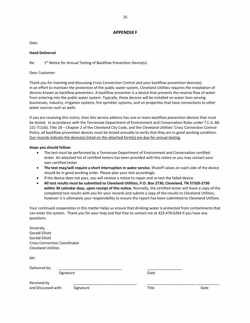
APPENDIX F Date Hand Delivered Re: 1st Notice for Annual Testing of Backflow Prevention Device(s) Dear Customer: Thank you for meeting and discussing Cross Connection Control and your backflow prevention device(s). In an effort to maintain the protection of the public water system, Cleveland Utilities requires the installation of devices known as backflow preventers. A backflow preventer is a device that prevents the reverse flow of water from entering into the public water system. Typically, these devices will be installed on water lines serving businesses, industry, irrigation systems, fire sprinkler systems, and on properties that have connections to other water sources such as wells. If you are receiving this notice, then this service address has one or more backflow prevention devices that must be tested. In accordance with the Tennessee Department of Environment and Conservation Rules under T.C.A. 68‐221‐711(6), Title 18 – Chapter 2 of the Cleveland City Code, and the Cleveland Utilities’ Cross Connection Control Policy; all backflow prevention devices must be tested annually to verify that they are in good working condition. Our records indicate the device(s) listed on the attached form(s) are due for annual testing. Steps you should follow:
The test must be performed by a Tennessee Department of Environment and Conservation certified tester. An attached list of certified testers has been provided with this notice or you may contact your own certified tester.
The test may/will require a short interruption in water service. Shutoff valves on each side of the device should be in good working order. Please plan your test accordingly.
If the device does not pass, you will receive a notice to repair and re‐test the failed device.
All test results must be submitted to Cleveland Utilities, P.O. Box 2730, Cleveland, TN 37320‐2730 within 30 calendar days, upon receipt of this notice. Normally, the certified tester will leave a copy of the completed test results with you for your records and submit a copy of the results to Cleveland Utilities; however it is ultimately your responsibility to ensure the report has been submitted to Cleveland Utilities.
Your continued cooperation in this matter helps us ensure that drinking water is protected from contaminants that can enter the system. Thank you for your help and feel free to contact me at 423‐478‐6264 if you have any questions. Sincerely, Gerald Elliott Gerald Elliott Cross Connection Coordinator Cleveland Utilities Att. Delivered by: _______________________________ _________________ Signature Date Received by _______________________________ ________________________ ___________ and Discussed with: Signature Title Date
27
Date Certified Mail (Name of Addressee) (Title of Addressee) (Name of Business) (Mailing Address of Business) Cleveland, TN (Zip Code) Re: 2nd Notice for Annual Testing of Backflow Prevention Device Dear (Addressee): In accordance with Cleveland Utilities’ Cross Connection Control Policy and the requirements of the Tennessee Department of Environment and Conservation, all backflow prevention devices must be tested annually to ensure that they are in good working condition. A notice for testing was given on (date) for the device(s) listed on the attached form(s). As of this date, Cleveland Utilities has not received the results of the annual test. If the results of the annual test(s) are not received by Cleveland Utilities within 30 calendar days upon receipt of this letter, termination of water service will be recommended to the Vice President of Water/Wastewater. I have enclosed the forms to be given to the tester to complete or the tester may use their own form. Please understand that these measures are put in place to protect the drinking water supply for all of our customers. Feel free to contact Gerald Elliott (Cross Connection Coordinator) at 423‐478‐6264 or myself at 423‐478‐0698 to discuss this matter further or if you have any questions. Sincerely, Steve Barger Environmental / Regulatory Compliance Department Supervisor Cleveland Utilities Att. Email: Mr. Ken Webb, President/CEO, Cleveland Utilities Mr. Craig T. Mullinax, Vice President of Water/Wastewater, Cleveland Utilities Mr. D. Byron Maples, P.E., Manager of Treatment Facilities, Cleveland Utilities Mr. Gerald Elliott, Cross Connection Coordinator, Cleveland Utilities
28
APPENDIX G
October 12, 2016 Hand Delivered Re: 1st Notice for Repair and Retest of Backflow Prevention Device To Whom It May Concern: In accordance with Cleveland Utilities’ Cross Connection Control Policy and the requirements of the Tennessee Department of Environment and Conservation, all backflow prevention devices must be tested annually to ensure that they are in good working condition. The annual test conducted on the device(s) listed on the attached form(s) indicated a failure which requires a repair and retest. The repair and retest must be conducted and all retest results must be submitted to Cleveland Utilities within 30 calendar days upon receipt of this notice. Your continued cooperation in this matter helps us ensure that the drinking water is protected from contaminants that can enter the system. Thank you for your help and feel free to contact me at 423‐478‐6264 if you have any questions. Sincerely, Cross Connection Coordinator Cleveland Utilities Att. Delivered by: _______________________________ Date: _________________ Signature Received by: _______________________________ Date: _________________ Signature
_______________________________ Title
October 12, 2016
29
Certified Mail (Name of Addressee) (Title of Addressee) (Name of Business) (Mailing Address of Business) Cleveland, TN (Zip Code) Re: 2nd Notice for Repair and Retest of Backflow Prevention Device(s) Dear (Addressee): In accordance with Cleveland Utilities’ Cross Connection Control Policy and the requirements of the Tennessee Department of Environment and Conservation, all backflow prevention devices must be tested annually to ensure that they are in good working condition. A notice for repair and retesting was given on (date) for the device(s) listed on the attached form(s): As of this date, Cleveland Utilities has not received the results of the retest(s). If the results of the retest(s) are not received by Cleveland Utilities within 30 calendar days upon receipt of this letter, termination of water service will be recommended to the Vice President of Water/Wastewater. I have enclosed the forms to be given to the tester to complete or the tester may use their own form. Please understand that these measures are put in place to protect the drinking water supply for all of our customers. Feel free to contact Gerald Elliott (Cross Connection Coordinator) at 423‐478‐6264 or myself at 423‐478‐0698 to discuss this matter further or if you have any questions. Sincerely, Steve Barger Environmental / Regulatory Compliance Department Supervisor Cleveland Utilities Att. Email: Mr. Ken WebbPresident/CEO, Cleveland Utilities Mr. Craig T. Mullinax, Vice President of Water/Wastewater, Cleveland Utilities Mr. D. Byron Maples, P.E., Manager of Treatment Facilities, Cleveland Utilities Mr. Gerald Elliott, Cross Connection Coordinator, Cleveland Utilities
30
APPENDIX H
CHAPTER 2
CROSS‐CONNECTIONS, ETC.
SECTION 18‐201. Definitions. 18‐202. Standards. 18‐203. Approval of state department of health required. 18‐204. Required statement from consumers with other supply sources. 18‐205. Inspection of cross‐connections. 18‐206. Utility's right‐of‐entry for inspection purposes. 18‐207. Correction of defects, etc. 18‐208. Protective devices. 18‐209. Labeling of water outlet not supplied by potable system.
18‐201. Definitions. The following definitions and terms shall apply in the interpretation and enforcement of this chapter:
(1) "Auxiliary intake." Any piping connection or other device whereby water may be secured from a source other than that normally used.
(2) "By‐pass." Any system of piping or other arrangement whereby the water may be diverted around any part or portion of a water purification plant.
(3) "Cross‐connection." Any physical connection whereby the public water supply is connected with any other water supply system, whether public or private, either inside or outside of any building or buildings, in such manner that a flow of water into the public water supply is possible either through the manipulation of valves or because of ineffective check or back‐pressure valves, or because of any other arrangement.
(4) "General Manager." Shall mean the general manager of the utility or officials or employees of the utility as may be designated by the general manager.
(5) "Interconnection." Any system of piping or other arrangement whereby the public water supply is connected directly with a sewer, drain, conduit, pool, storage reservoir or other device which does or may contain sewage or other waste or liquid which would be capable of imparting contamination to the public water supply.
(6) "Person." Any and all persons, natural or artificial, including any individual firm or association, and any municipal or private corporation organized or existing under the laws this or any other state or country.
(7) "Public water supply." The Cleveland utilities‐water division furnishing to the city and the surrounding areas of the county for general use and which supply is recognized as the public water supply by the state department of public health.
(8) "Utility." Shall mean the Cleveland utilities, a department of the city or duly appointed officials or representatives of Cleveland utilities. (1981Code, § 23‐135)
18‐202. Standards. The Cleveland utilities public water supply is to comply with
31
Tennessee Code Annotated, § 68‐221‐101 and § 68‐221‐104 as well as the rules and regulations for public water supplies, legally adopted in accordance with this code, which pertain to cross‐connections, auxiliary intakes, by‐passes and interconnections, and establish an effective ongoing program to control these undesirable water uses. (1981 Code, § 23‐136)
18‐203. Approval of state department of health required. It shall be unlawful for any person to cause a cross‐connection, auxiliary intake, by‐pass or interconnection to be made, or allow one to exist for any purpose whatsoever, unless the construction and operation of same has been approved by the state department of health, and the operation of such cross‐connection, auxiliary, intake, by‐pass or interconnection is at all times under the direct supervision of the general manager of the utility. (1981 Code, § 23‐137)
18‐204. Required statement from consumers with other supply sources. Any person whose premises are supplied with water from the public water supply, and who also has on the same premises a separate source of water supply or stores water in an uncovered or unsanitary storage reservoir from which the water stored therein is circulated through a piping system, shall file with the general manager of the utility a statement of the nonexistence of unapproved or unauthorized cross‐connections, auxiliary intakes, by‐passes or interconnections. Such statement shall also contain an agreement that no cross‐connection, auxiliary intake, by‐pass or interconnection will be permitted upon the premises. (1981 Code, § 23‐138)
18‐205. Inspection of cross‐connections. It shall be the duty of the utility to cause inspections to be made of all properties served by the public water supply where cross‐connections with the public water supply are deemed possible. The frequency of inspections and reinspections based on potential health hazards involved shall be as established by the utility and as approved by the state department of health. (1981 Code, § 23‐139)
18‐206. Utility's right‐of‐entry for inspection purposes. The officials of the utility, or its authorized representative, shall have the right to enter at any reasonable time, any property served by a connection to the utility for the purpose of inspecting the piping system or systems thereof for cross‐connections, auxiliary intakes, by‐passes, or interconnections. On request, the owner, lessee, or occupant of any property so served shall furnish to the utility any pertinent information regarding the piping system or systems on such property. The refusal of such information or refusal of access, when requested, shall be deemed evidence of the presence of cross‐connections. (1981Code, § 23‐140)
18‐207. Correction of defects, etc. (1) Any person who had cross‐connections, auxiliary intakes, by‐passes or interconnections in violation of the provisions of this chapter on November 28, 1977, shall be allowed a reasonable time within which to comply with the provisions of this chapter. After a thorough investigation of existing conditions and an appraisal of the time required to complete the work, the amount of time shall be designated by the utility.
(2) The failure to correct conditions threatening the safety of the public water system as prohibited by this chapter and Tennessee Code Annotated, § 68‐221‐104, within a reasonable time and within the time limits set by the utility, shall be grounds for denial of water service. If
32
proper protection has not been provided after a reasonable time, the utility shall give the customer legal notification that water service is to be discontinued, and then physically separate the public water supply from the customer's on‐site piping system in such a manner that the two (2) systems cannot again be connected by an unauthorized person.
(3) Where cross‐connections, interconnections, auxiliary intakes, or by‐passes are found which constitute an extreme hazard of immediate concern of contaminating the public water system, the general manager of the utility shall require that immediate corrective action be taken to eliminate the threat to the public water system. Immediate steps shall be taken to disconnect the public water supply from the on‐site piping system unless the eminent hazard is corrected immediately. (1981 Code, § 23‐141)
18‐208. Protective devices. (1) Where the nature of use of the water supplied a premises by the utility is such that is deemed:
(a) Impractical to provide an effective air‐gap separation; (b) That the owner and/or occupant of the premises cannot or is not willing to
demonstrate to the official in charge of the utility, or his designated representative, that the water use and protective features of the plumbing are such as to propose no threat to the safety or potability of the water supply;
(c) That the nature and mode of operation within a premises are such that frequent alterations are made to the plumbing;
(d) There is a likelihood that protective measures may be subverted, altered or disconnected;
The utility shall require the use of an approved protective device on the service line serving the premises to assure that any contamination that may originate in the customer's premises is contained therein. The protective devices shall be a reduced pressure zone type backflow preventer approved by the state department of health as to the manufacturer, model and size. The method of installation of the backflow protective devices shall be approved by the utility prior to installation and shall comply with the criteria set forth by the state department of health. The installation shall be at the expense of the owner or occupant of the premises.
(2) The utility shall have the right to inspect and test the device or devices on an annual basis or whenever deemed necessary. Water service shall not be disrupted to test the service without the knowledge of the occupant of the premises.
(3) Where the use of water is critical to the continuance of normal operations or protection of life, property, or equipment, duplicate units shall be provided to avoid the necessity of discontinuing water service to test or repair the protective device or devices. Where only one unit is installed and the continuance of service is critical, the utility shall notify, in writing, the occupant of the premises of plans to discontinue water service and arrange for a mutually acceptable time to test and/or repair the device. The utility shall require the occupant of the premises to make all repairs indicate promptly, and the expense of such repairs shall be borne by the owner or occupant of the premises. These repairs shall be made by qualified personnel, acceptable to the utility.
(4) If necessary, water service shall be discontinued (following legal notification) for failure to maintain backflow prevention devices in proper working order. Likewise the removal, by‐passing or altering of the protective devices in such a manner as to make them ineffective shall constitute grounds for discontinuance of water service. Water service to such premises
33
shall not be restored until the customer has corrected or eliminated such conditions or defects to the satisfaction of the utility. (1981 Code, § 23‐142)
18‐209. Labeling of water outlet not supplied by potable system. The potable water supply made available on the properties served by the public water supply shall be protected from possible contamination as specified herein. Any water outlet which could be used for potable or domestic purposes and which is not supplied by the potable system must be labeled in a conspicuous manner as:
W A T E R U N S A F E F O R D R I N K I N G
A minimum acceptable sign shall have white letters one‐inch high located on a red background. (1981 Code, § 23‐143)