50
Crude&RefinedProductSampler S Y S T E M S U P P O R T M A N U A L CNR-2LM-6M
Crude & Refined Product SamplerS Y S T E M S U P P O R T M A N U A L
CNR-2LM-6M

CNR-2LM-6MINSTRUCTION & OPERATING
MANUALVersion: 01122005


YZ Systems, Inc. • 3101 Pollok Drive • Conroe, Texas • USA • 77303 • P: 936.788.5593 • F: 936.788.5720Page ICNR-LM-6M ver.01122005
CNR-2LM-6 M TCNR-2LM-6 M TCNR-2LM-6 M TCNR-2LM-6 M TCNR-2LM-6 M TABLEABLEABLEABLEABLE OFOFOFOFOF C C C C CONTENTSONTENTSONTENTSONTENTSONTENTS
CNR-2LM-6M Table of Contents ...................................................................................................... I
Section 1: First Things To Know ....................................................................................................1How to Use this Manual .......................................................................................................................1Typographic Conventions ....................................................................................................................1Getting Help .........................................................................................................................................1Operation Specifications .....................................................................................................................2Theory of Operation ............................................................................................................................3System Accessories ...........................................................................................................................3
Section 2: System Installation.........................................................................................................5Standard System Components ...........................................................................................................5System Flow Schematic .....................................................................................................................6Standard System Mounting .................................................................................................................7
Section 3: System Control & Electronics ......................................................................................9Overview .............................................................................................................................................9
Section 4: Programming for Proportional-to-Flow Operation ................................................... 11Setting Operator Input Parameters ................................................................................................... 11
Section 5: Programming for Proportional-to-Time Operation ..................................................15Setting Operator Input Parameters ...................................................................................................15
Section 6: Mechanical System ......................................................................................................17Overview ...........................................................................................................................................17Sample Pump/Balance Valve Assembly ...........................................................................................18Filter Regulator ..................................................................................................................................18Pneumatic Relay ...............................................................................................................................185-Way Cross .....................................................................................................................................19DuraSite Portable Sample Vessel .....................................................................................................20
Section 7: System Operation ........................................................................................................21Preparing The System for Operation ................................................................................................21Sample Pump Priming ......................................................................................................................21Product Line Test ..............................................................................................................................21Portable Sample Vessel Connection .................................................................................................21
Section 8: System Maintenance ...................................................................................................23Preventative Maintenance Schedule .................................................................................................23
Recommended Maintenance Schedule ......................................................................................23Monthly Inspection ....................................................................................................................23Annual Inspection .....................................................................................................................23Bi-Annual Inspection .................................................................................................................23
Recommended Spare Parts List .................................................................................................23
Section 9: System Troubleshooting .............................................................................................. 25How to Use This Section ...................................................................................................................25
For Additional Help .......................................................................................................................25Step-by-Step Resolution ..............................................................................................................25
Actuation Gas System.......................................................................................................................26Actuation Gas System Troubleshooting Steps ............................................................................26
Z-65 Controller ...................................................................................................................................26Controller Electrical Power Troubleshooting Steps .....................................................................27Controller Counter Mode Troubleshooting Steps .........................................................................28Controller Timer Mode Troubleshooting Steps .............................................................................30
Pump Performance ...........................................................................................................................31Pump Performance Troubleshooting Steps ................................................................................31
Appendix A: Illustrations ................................................................................................................33CNR-2P Sample Pump, Assembled .................................................................................................33CNR-2P Balance Valve Assembly, Exploded View ............................................................................345-Way Cross Assembly.....................................................................................................................35DuraSite ............................................................................................................................................36Filter Regulator, Assembled ..............................................................................................................37Filter Regulator, Exploded View .........................................................................................................38Pneumatic Relay ...............................................................................................................................39Electroinic Control Components .......................................................................................................40Electroinic Wiring Control Document ................................................................................................41

YZ Systems, Inc. • 3101 Pollok Drive • Conroe, Texas • USA • 77303 • P: 936.788.5593 • F: 936.788.5720Page 1CNR-LM-6M ver.01122005
SSSSSECTIONECTIONECTIONECTIONECTION 1: F 1: F 1: F 1: F 1: FIRSTIRSTIRSTIRSTIRST T T T T THINGSHINGSHINGSHINGSHINGS T T T T TOOOOO K K K K KNOWNOWNOWNOWNOW A A A A ABOUTBOUTBOUTBOUTBOUT T T T T THEHEHEHEHE CNR-2 CNR-2 CNR-2 CNR-2 CNR-2
How to Use this Manual
The CNR-LM-6M Operations Manual is a step-by-step guide containing the procedures needed towork with the CNR-LM-6M System.
The CNR-2LM System Series of samplers implementthe most advanced technology available in theindustry. It is recommended that the techniciansworking with the CNR-2LM Systems study themanual prior to initiating work on the system for thefirst time.
Typographic Conventions
To aide in readability, this manual uses severaltypographic conventions. References to illustrations,photographs, and other related content will appear initalicized text along with the location of where to find theitem in the manual. Digital versions of the manual,available in Adobe Acrobat™ PDF format, will behighlighted further in blue italic text indicating the copyretains a hyperlink to the referenced item.
Measurement units are listed in italic parenthesis textfollowing their US standard equivalent. As an example,for defining a distance, 15' (4.5 meters), is how the textwill appear throughout the manual.
Items that require action, for example the pressing of a keyfor programming the controller, will feature the action item insentence case Bold Text followed in normal text by theitem such as, the Up Arrow key or Main Power switch.
™ Adobe Acrobat & Acrobat Reader are trademarks of Adobe Systems, Inc.
Getting Help
This manual provides solutions to typical questionsabout the CNR-LM-6 system. If the answer can notbe found within this manual, contact YZ Systems at:
T: 1.936.788.5593T: 1.800.653.9435F: 1.936.788.5720Em: [email protected]
When calling, have this manual close at hand.Whether calling or writing, please include in yourcommunique the following information:
• The serial number of the CNR-2LM System andthe version number of this manual. The serialnumber is located on the inside of the enclosuredoor. The version number of this manual islocated at the bottom of each page.
• A description of the problem and, if applicable theactions of the technical personnel when the problemoccurred.

YZ Systems, Inc. • 3101 Pollok Drive • Conroe, Texas • USA • 77303 • P: 936.788.5593 • F: 936.788.5720Page 2 CNR-LM-6M ver.01122005
SSSSSECTIONECTIONECTIONECTIONECTION 1: F 1: F 1: F 1: F 1: FIRSTIRSTIRSTIRSTIRST T T T T THINGSHINGSHINGSHINGSHINGS T T T T TOOOOO K K K K KNOWNOWNOWNOWNOW A A A A ABOUTBOUTBOUTBOUTBOUT T T T T THEHEHEHEHE CNR-2 CNR-2 CNR-2 CNR-2 CNR-2
1
Operation Specifications
Maximum Output: 6.8 gallons/day (25.3 liters/day)
Maximum Operating Pressure: 1,800 psig(124 Bar (g)
Pump Displacement: .25 - 1.8 cc/StrokeOperating Temp Range: 0 to 140 degrees F.
(17°C to 60°C)Power Supply: Battery PackActuation Gas; 100 psi Instrument
Quality GasProduct Sample Input Signal: Dry Contact Pulse
Note: at temperatures below 32º F (0º C), condition-ing of the actuation gas supply may be required.Where the actuation gas supply has a high watercontent and/or a low hydrocarbon dew point, addi-tional actuation gas filtration or heating of the actua-tion gas supply may be necessary. Bottled nitrogencan also be used during cold operating conditions toavoid condensation in the actuation gas supply line.In addition, operation at extreme temperatures mayaffect system performance. To enhance the perfor-mance of this system, adequate heat should beprovided to maintain an operating environmentabove 30° F (-1º C).
YZ Systems, Inc. • 3101 Pollok Drive • Conroe, Texas • USA • 77303 • P: 936.788.5593 • F: 936.788.5720Page 3CNR-LM-6M ver.01122005
SSSSSECTIONECTIONECTIONECTIONECTION 1: F 1: F 1: F 1: F 1: FIRSTIRSTIRSTIRSTIRST T T T T THINGSHINGSHINGSHINGSHINGS T T T T TOOOOO K K K K KNOWNOWNOWNOWNOW A A A A ABOUTBOUTBOUTBOUTBOUT T T T T THEHEHEHEHE CNR-2 CNR-2 CNR-2 CNR-2 CNR-2
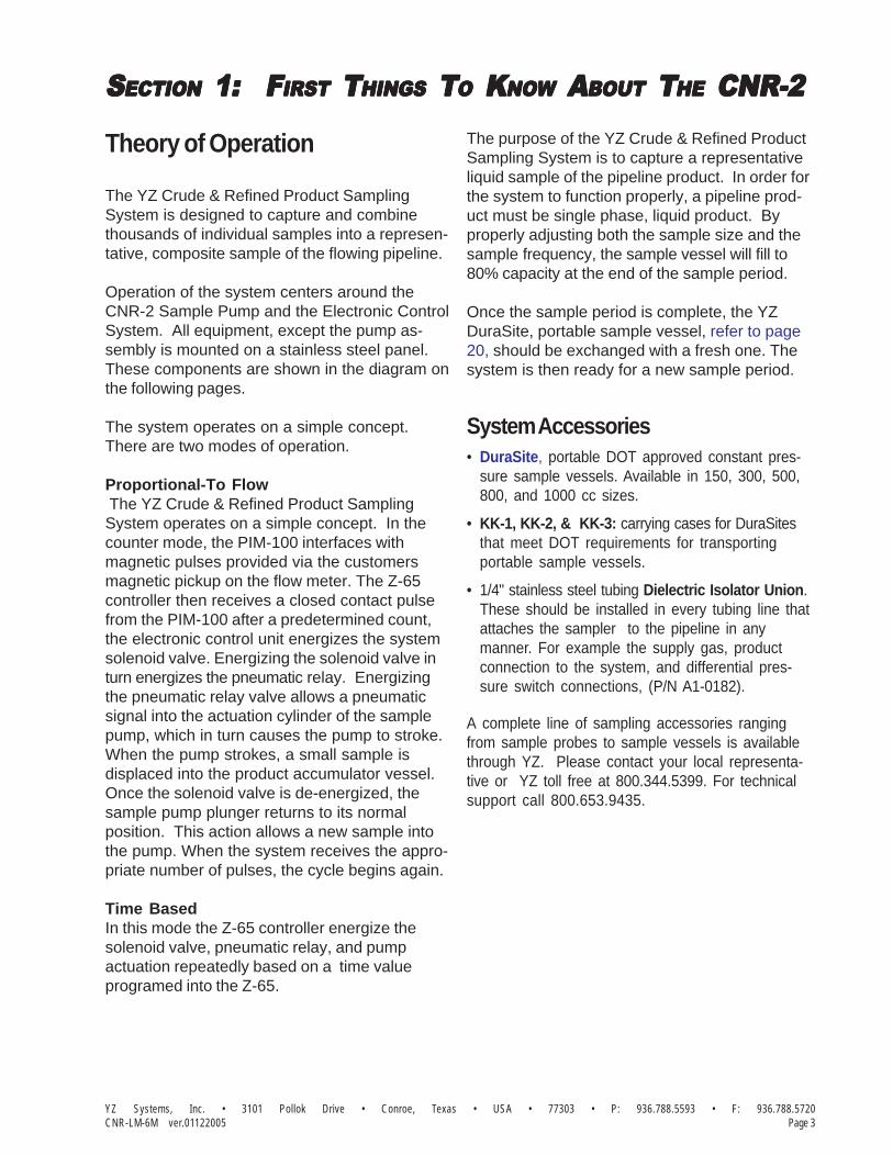
Theory of Operation
The YZ Crude & Refined Product SamplingSystem is designed to capture and combinethousands of individual samples into a represen-tative, composite sample of the flowing pipeline.
Operation of the system centers around theCNR-2 Sample Pump and the Electronic ControlSystem. All equipment, except the pump as-sembly is mounted on a stainless steel panel.These components are shown in the diagram onthe following pages.
The system operates on a simple concept.There are two modes of operation.
Proportional-To Flow The YZ Crude & Refined Product SamplingSystem operates on a simple concept. In thecounter mode, the PIM-100 interfaces withmagnetic pulses provided via the customersmagnetic pickup on the flow meter. The Z-65controller then receives a closed contact pulsefrom the PIM-100 after a predetermined count,the electronic control unit energizes the systemsolenoid valve. Energizing the solenoid valve inturn energizes the pneumatic relay. Energizingthe pneumatic relay valve allows a pneumaticsignal into the actuation cylinder of the samplepump, which in turn causes the pump to stroke.When the pump strokes, a small sample isdisplaced into the product accumulator vessel.Once the solenoid valve is de-energized, thesample pump plunger returns to its normalposition. This action allows a new sample intothe pump. When the system receives the appro-priate number of pulses, the cycle begins again.
Time BasedIn this mode the Z-65 controller energize thesolenoid valve, pneumatic relay, and pumpactuation repeatedly based on a time valueprogramed into the Z-65.
The purpose of the YZ Crude & Refined ProductSampling System is to capture a representativeliquid sample of the pipeline product. In order forthe system to function properly, a pipeline prod-uct must be single phase, liquid product. Byproperly adjusting both the sample size and thesample frequency, the sample vessel will fill to80% capacity at the end of the sample period.
Once the sample period is complete, the YZDuraSite, portable sample vessel, refer to page20, should be exchanged with a fresh one. Thesystem is then ready for a new sample period.
System Accessories• DuraSite, portable DOT approved constant pres-
sure sample vessels. Available in 150, 300, 500,800, and 1000 cc sizes.
• KK-1, KK-2, & KK-3: carrying cases for DuraSitesthat meet DOT requirements for transportingportable sample vessels.
• 1/4" stainless steel tubing Dielectric Isolator Union.These should be installed in every tubing line thatattaches the sampler to the pipeline in anymanner. For example the supply gas, productconnection to the system, and differential pres-sure switch connections, (P/N A1-0182).
A complete line of sampling accessories rangingfrom sample probes to sample vessels is availablethrough YZ. Please contact your local representa-tive or YZ toll free at 800.344.5399. For technicalsupport call 800.653.9435.

YZ Systems, Inc. • 3101 Pollok Drive • Conroe, Texas • USA • 77303 • P: 936.788.5593 • F: 936.788.5720Page 4 CNR-LM-6M ver.01122005
SSSSSECTIONECTIONECTIONECTIONECTION 1: F 1: F 1: F 1: F 1: FIRSTIRSTIRSTIRSTIRST T T T T THINGSHINGSHINGSHINGSHINGS T T T T TOOOOO K K K K KNOWNOWNOWNOWNOW A A A A ABOUTBOUTBOUTBOUTBOUT T T T T THEHEHEHEHE CNR-2 CNR-2 CNR-2 CNR-2 CNR-2
Notes

YZ Systems, Inc. • 3101 Pollok Drive • Conroe, Texas • USA • 77303 • P: 936.788.5593 • F: 936.788.5720Page 5CNR-LM-6M ver.01122005
SSSSSECTIONECTIONECTIONECTIONECTION 2: 2: 2: 2: 2: S S S S SYYYYYSTEMSTEMSTEMSTEMSTEM I I I I INSTNSTNSTNSTNSTALLAALLAALLAALLAALLATIONTIONTIONTIONTION
Standard System ComponentsStandard primary components of the CNR-2LM includethe following:
• Sample Pump/Balance Valve, figure 1. Probemounted, pneumatically actuated CNR-2P SamplePump.
• System Enclosure, figure 2. Five-Way Cross,Pneumatic Control Components, System ControlElectronics.
• System Vessel Support Rack, figure 2. StainlessSteel support rack for customer’s 2” DuraSite portableSample Vessel.
• Five-Way Cross, figure 2. mounts the PressureGage, Relief Valve, Product Isolation, and ProductRemoval Valves.
figure 1
ISOLATION VALVE
FLOW
SUPPLY PROBE
(FROM CONTROL PANEL)PNEUMATIC SUPPLY
(TO CONTROL PANEL)PRODUCT OUT
figure 2
VALVEPNEUMATIC RELAY
19 7/8"
PIM-100
PSI
Z-65 TIMERMODEL
Factory
ApprovedSystem
REGULATORFILTER
CABLE ENTRY)(7/16" Max.
LIQUID TIGHTFITTING
Pulse Input Module
4096
Input Adj.
32
PIM-100
21 4 8 16
512
256
12864
1024
2048
Mutual
IG 1
-SIG 2
655
36
163
8481
92
327
68
13
1072
PO
WE
R2
621
44
Red-1
White-3
Black-5
15 3/8"
RELIEF VALVE
SOLENOID VALVE
(1/8" TUBING)OUT TO DURASITEPRODUCT SAMPLE
VESSEL RACK
(BY CUSTOMER)
(1/4" FNPT)ROB VALVE
1000
500
psi
1500
2000

YZ Systems, Inc. • 3101 Pollok Drive • Conroe, Texas • USA • 77303 • P: 936.788.5593 • F: 936.788.5720Page 6 CNR-LM-6M ver.01122005
SSSSSECTIONECTIONECTIONECTIONECTION 2: 2: 2: 2: 2: S S S S SYYYYYSTEMSTEMSTEMSTEMSTEM I I I I INSTNSTNSTNSTNSTALLAALLAALLAALLAALLATIONTIONTIONTIONTION
System Flow Schematicfigure 3
PRESSURE GAUGE
AIR RELAY VALVE
Z-65 CONTROLLER
PIM-100
ISOLATIONVALVE
SAMPLING
L E G E N D
PUMP
CNR-2
RELIEF VALVE
INSTRUMENT AIR IN100 PSI
PULSED VOLTAGE ORDRY CONTACT OR
DPS SIGNAL INTO Z-65 CONTROLLER
(BY CUSTOMER)
(BY CUSTOMER)UP SIGNAL
MAGNETIC PICK
(BY CUSTOMER)
ENCLOSURE
S
Inp ut Adj.
Pulse Input Module
321 16
PIM-100
42 8
1024
12864
512
256
4096
2048
163
8481
92
2
1
-SIG
+SIG
1310
726
5536
PO
WE
R26
2144
Bla ck-5
Whi te-3
Red-1
SYSTEMCONTROL
PRODUCT LINE(BY CUSTOMER)
CNR-2 PROBE
ROB VALVE
ISOLATION VALVESAMPLE VESSEL
PI
(BY CUSTOMER)PRECHARGE IN
DURASITE
DURASITE
PI
DURASITE
PI
327
68
Mutual
Approved
System
Factory
PIPELINE
NORMALLY CLOSED VALVE
NORMALLY OPEN VALVE
PRESSURE REGULATOR
SOLENOID VALVE
PRODUCT
ELECTRICAL
RUPTURE DISC
S
PNEUMATIC
Pulse Input Module
102
4
Inpu t Adj.
PIM-100
1
32
1642 8
128
64
512
256
+SIG 1
2-SIG
3276
8
204
84
096
1638
48
192
131
072
6553
6
PO
WE
R2
621
44
Black-5
White-3
Re d-1
PI
MutualApprove dSystem
Factory

YZ Systems, Inc. • 3101 Pollok Drive • Conroe, Texas • USA • 77303 • P: 936.788.5593 • F: 936.788.5720Page 7CNR-LM-6M ver.01122005
SSSSSECTIONECTIONECTIONECTIONECTION 2: 2: 2: 2: 2: S S S S SYYYYYSTEMSTEMSTEMSTEMSTEM I I I I INSTNSTNSTNSTNSTALLAALLAALLAALLAALLATIONTIONTIONTIONTION
ACTUATION GAS IN(BY CUSTOMER)(1/4" FNPT)
4 1/4"
DPS SIGNAL IN
(BY CUSTOMER)TO Z-65 CONTROLLER
PULSED VOLTAGE ORDRY CONTACT OR
2" NOM. PIPEU-BOLT ASSY. (2)
Standard System Mountingfigure 4
Panel InstallationThe sampling system should be located as close aspossible to the pipeline. 2" U-bolt assemblies areprovided to mount the panel to a 2" vertical pole.
Pneumatic SupplyA 1/4" connection on the panel is provided for acontinuous pneumatic supply (100 psi). Thenecessary regulator, solenoid valve, etc. isprovided on the sampling panel.
Pump InstallationThe CNR-2 sample pump is designed to bemounted directly to a threaded connection on thepipeline. The probe should be installed such thatthe tip of the probe will be located in the center 1/3of the pipeline after installation. Next you mustinstall 1/4" stainless steel tubing between theconnection on the back of the panel marked forpump actuation, and the connection at the top ofthe pump. Finally connect 1/4" stainless steeltubing from the discharge connection of the pumpbalance valve to the connection on the back of thepanel marked for product.
ISOLATION VALVE
FLOW
SUPPLY PROBE
CACACACACAUTION:UTION:UTION:UTION:UTION:Excessive tubing lengths should be avoided. Installa-tion of the sample system enclosure should be asclose to the point of sample removal and the samplepump as possible. If longer tubing lengths are requiredconsult YZ Systems Technical Services at;800.653.9435 or 1.936.788.5593.
Pump Sample SizeThe sample size of the CNR-2 is adjustablefrom 0.25 to 1.8 cc/stroke. The sample grabsize of the pump is adjusted by loosening thelock/seal nut on top of the pump and turningthe volume adjustment screw in to decreasethe sample volume or out to increase thesample volume. Once the new sample size hasbeen set, the lock/seal nut should be retight-ened, refer to Appendix A, page33.

YZ Systems, Inc. • 3101 Pollok Drive • Conroe, Texas • USA • 77303 • P: 936.788.5593 • F: 936.788.5720Page 8 CNR-LM-6M ver.01122005
SSSSSECTIONECTIONECTIONECTIONECTION 2: 2: 2: 2: 2: S S S S SYYYYYSTEMSTEMSTEMSTEMSTEM I I I I INSTNSTNSTNSTNSTALLAALLAALLAALLAALLATIONTIONTIONTIONTION
Notes

YZ Systems, Inc. • 3101 Pollok Drive • Conroe, Texas • USA • 77303 • P: 936.788.5593 • F: 936.788.5720Page 9CNR-LM-6M ver.01122005
SSSSSECTIONECTIONECTIONECTIONECTION 3: 3: 3: 3: 3: S S S S SYYYYYSTEMSTEMSTEMSTEMSTEM C C C C CONTRONTRONTRONTRONTROLOLOLOLOL & E & E & E & E & ELECTRLECTRLECTRLECTRLECTRONICSONICSONICSONICSONICS
Overview
The electronic control package provided withyour sampling system consists of a Z-65/6.1Timer/Counter, and a PIM-100 pulse interfacemodule. The Z-65 drives a low power solenoidthat in turn drives a pneumatic relay valvecapable of actuating a large volume pump.
In the timer mode, the Z-65 can be programmedto act a recycling timer and actuates the pumpafter a preset amount of time passes. This timeis set with the rotary and mode switches on theface of the Z-65 and the jumper located underthe faceplate.
In the counter mode, the Z-65 can be set up tocount a dry contact pulse provided by PIM-100,which is generated after a configured number ofmagnetic pulses from the customers flow meterhave arrived. After the unit receives a specifiednumber of pulses, it will stroke the pump. Thetime is set with the rotary and mode switches onthe face of the Z-65 and the jumper locatedunder the faceplate.
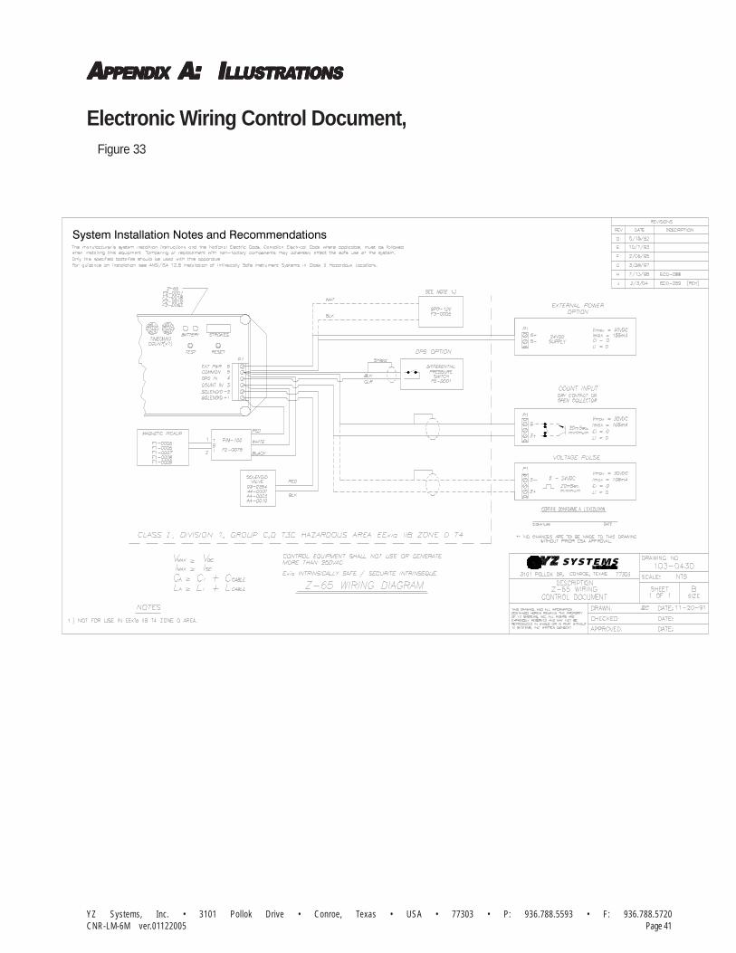
The control package is powered by an on-boardbattery pack. You are also required to providedry contacts at terminals 3 and 5 if you will beoperating the unit in counter mode without thePIM-100 interface. All electronics are certifiedintrinsically safe and are rated for use in Class I,Division 1, Groups C and D hazardous locations,refer to electronic control document, on page 41.
SAFETY NOSAFETY NOSAFETY NOSAFETY NOSAFETY NOTESTESTESTESTES• Always use extreme care when performing mainte-
nance on Sampling Systems. Always take necessarymeasures to assure that electrical classification in thearea is considered, before, and during all repairs, andthat necessary steps are taken to maintain properelectrical procedures for the classification of the area.

YZ Systems, Inc. • 3101 Pollok Drive • Conroe, Texas • USA • 77303 • P: 936.788.5593 • F: 936.788.5720Page 10 CNR-LM-6M ver.01122005
SSSSSECTIONECTIONECTIONECTIONECTION 3: 3: 3: 3: 3: S S S S SYYYYYSTEMSTEMSTEMSTEMSTEM C C C C CONTRONTRONTRONTRONTROLOLOLOLOL & E & E & E & E & ELECTRLECTRLECTRLECTRLECTRONICSONICSONICSONICSONICS
Notes
YZ Systems, Inc. • 3101 Pollok Drive • Conroe, Texas • USA • 77303 • P: 936.788.5593 • F: 936.788.5720Page 11CNR-LM-6M ver.01122005
SSSSSECTIONECTIONECTIONECTIONECTION 44444::::: P P P P PRRRRROGRAMMINGOGRAMMINGOGRAMMINGOGRAMMINGOGRAMMING FORFORFORFORFOR P P P P PRRRRROPOROPOROPOROPOROPORTIONTIONTIONTIONTIONALALALALAL-----TTTTTOOOOO-F-F-F-F-FLLLLLOOOOOWWWWW O O O O OPERAPERAPERAPERAPERATIONTIONTIONTIONTION
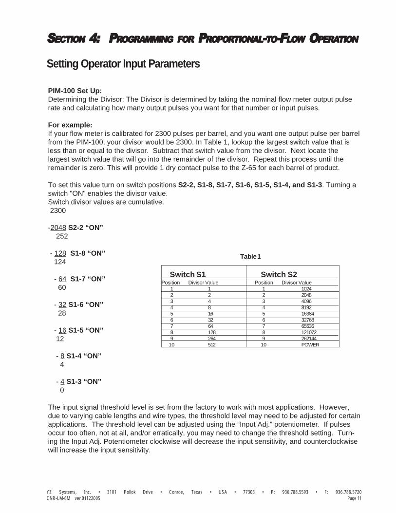
PIM-100 Set Up:Determining the Divisor: The Divisor is determined by taking the nominal flow meter output pulserate and calculating how many output pulses you want for that number or input pulses.
For example:If your flow meter is calibrated for 2300 pulses per barrel, and you want one output pulse per barrelfrom the PIM-100, your divisor would be 2300. In Table 1, lookup the largest switch value that isless than or equal to the divisor. Subtract that switch value from the divisor. Next locate thelargest switch value that will go into the remainder of the divisor. Repeat this process until theremainder is zero. This will provide 1 dry contact pulse to the Z-65 for each barrel of product.
To set this value turn on switch positions S2-2, S1-8, S1-7, S1-6, S1-5, S1-4, and S1-3. Turning aswitch "ON" enables the divisor value.Switch divisor values are cumulative. 2300
-2048 S2-2 “ON” 252
- 128 S1-8 “ON” 124
- 64 S1-7 “ON” 60
- 32 S1-6 “ON” 28
- 16 S1-5 “ON” 12
- 8 S1-4 “ON” 4
- 4 S1-3 “ON” 0
The input signal threshold level is set from the factory to work with most applications. However,due to varying cable lengths and wire types, the threshold level may need to be adjusted for certainapplications. The threshold level can be adjusted using the “Input Adj.” potentiometer. If pulsesoccur too often, not at all, and/or erratically, you may need to change the threshold setting. Turn-ing the Input Adj. Potentiometer clockwise will decrease the input sensitivity, and counterclockwisewill increase the input sensitivity.
Switch S1 Switch S2Position Divisor Value Position Divisor Value 1 1 1 1024 2 2 2 2048 3 4 3 4096 4 8 4 8192 5 16 5 16384 6 32 6 32768 7 64 7 65536 8 128 8 121072 9 264 9 262144 10 512 10 POWER
Table 1
Setting Operator Input Parameters

YZ Systems, Inc. • 3101 Pollok Drive • Conroe, Texas • USA • 77303 • P: 936.788.5593 • F: 936.788.5720Page 12 CNR-LM-6M ver.01122005
SSSSSECTIONECTIONECTIONECTIONECTION 44444::::: P P P P PRRRRROGRAMMINGOGRAMMINGOGRAMMINGOGRAMMINGOGRAMMING FORFORFORFORFOR P P P P PRRRRROPOROPOROPOROPOROPORTIONTIONTIONTIONTIONALALALALAL-----TTTTTOOOOO-F-F-F-F-FLLLLLOOOOOWWWWW O O O O OPERAPERAPERAPERAPERATIONTIONTIONTIONTION
Setting Operator Input Parameters
Z-65 Controller Set UpProportional To Flow Mode
The Mode Switches should be set as follows:#1 Power "On"
#2 Timer/Counter
#3 DPS Bypass
#4 Count Dry
SystemMutual
Approved
Factory
figure 5

YZ Systems, Inc. • 3101 Pollok Drive • Conroe, Texas • USA • 77303 • P: 936.788.5593 • F: 936.788.5720Page 13CNR-LM-6M ver.01122005
SSSSSECTIONECTIONECTIONECTIONECTION 44444::::: P P P P PRRRRROGRAMMINGOGRAMMINGOGRAMMINGOGRAMMINGOGRAMMING FORFORFORFORFOR P P P P PRRRRROPOROPOROPOROPOROPORTIONTIONTIONTIONTIONALALALALAL-----TTTTTOOOOO-F-F-F-F-FLLLLLOOOOOWWWWW O O O O OPERAPERAPERAPERAPERATIONTIONTIONTIONTION
The two orange time/count totalization knobsshould be set to achieve the desired number ofinput pulses to count before initiating a strokeof the pump. This number should be determinedusing the example on the following page.
Sample Vessel Size x 80% = Grabs Required/Sample Cycle. Sample Grab Size
ie: 500cc Vessel x 80% = 400cc = 444 Grabs Required .9 cc/Grab
Pulse/Metered Volume (from PIM-100) x Monthly Average Flow =Pulses/Sample Cycle
ie: 1 Pulse/BBL x 15,000 BBL/Month = 15,000 Pulses/Sample Cycle
Pulses/Sample Cycle = Pulses/Grab (Z-65 Counter Setting) Grabs Required
ie: 15,000 Pulses/Sample Cycle = 33.78 Pulses/Grab 444 Grabs Required
Round The Pulses/Grab calculation up to thenext whole number and enter in the Z-65 countersetting. The two orange time/count totalizationknobs should be set to achieve the desirednumber of input pulses to count before initiatinga stroke of the pump.
Verify switch positions & Press the TEST Buttonto begin sampling.
NOTE: The counter setting (34 pulses)corresponds to the dial setting shown forthe Z65 model with the counter rangesetting in the factory position (jumperon the two left pins).
Z-65 Controller Set Up
34 pulses
Example
32
09
6
87
1
32
5 4
09 1
678
5 4
figure 6
Setting Operator Input Parameters
YZ Systems, Inc. • 3101 Pollok Drive • Conroe, Texas • USA • 77303 • P: 936.788.5593 • F: 936.788.5720Page 14 CNR-LM-6M ver.01122005
SSSSSECTIONECTIONECTIONECTIONECTION 44444::::: P P P P PRRRRROGRAMMINGOGRAMMINGOGRAMMINGOGRAMMINGOGRAMMING FORFORFORFORFOR P P P P PRRRRROPOROPOROPOROPOROPORTIONTIONTIONTIONTIONALALALALAL-----TTTTTOOOOO-F-F-F-F-FLLLLLOOOOOWWWWW O O O O OPERAPERAPERAPERAPERATIONTIONTIONTIONTION
Notes

YZ Systems, Inc. • 3101 Pollok Drive • Conroe, Texas • USA • 77303 • P: 936.788.5593 • F: 936.788.5720Page 15CNR-LM-6M ver.01122005
SSSSSECTIONECTIONECTIONECTIONECTION 5: 5: 5: 5: 5: P P P P PRRRRROGRAMMINGOGRAMMINGOGRAMMINGOGRAMMINGOGRAMMING FORFORFORFORFOR P P P P PRRRRROPOROPOROPOROPOROPORTIONTIONTIONTIONTIONALALALALAL-----TTTTTOOOOO-T-T-T-T-TIMEIMEIMEIMEIME O O O O OPERAPERAPERAPERAPERATIONTIONTIONTIONTION
Setting Operator Input Parameters
SystemMutual
Approved
Factory
Z-65 Controller Set UpProportional To Time Mode
The Mode Switches should be set as follows
#1 Power "On"
#2 Timer/Counter
#3 DPS Bypass
#4 Count Dry
figure 7

YZ Systems, Inc. • 3101 Pollok Drive • Conroe, Texas • USA • 77303 • P: 936.788.5593 • F: 936.788.5720Page 16 CNR-LM-6M ver.01122005
SSSSSECTIONECTIONECTIONECTIONECTION 5: 5: 5: 5: 5: P P P P PRRRRROGRAMMINGOGRAMMINGOGRAMMINGOGRAMMINGOGRAMMING FORFORFORFORFOR P P P P PRRRRROPOROPOROPOROPOROPORTIONTIONTIONTIONTIONALALALALAL-----TTTTTOOOOO-T-T-T-T-TIMEIMEIMEIMEIME O O O O OPERAPERAPERAPERAPERATIONTIONTIONTIONTION
= # of Pump Strokes Required/Sample Cycle
= Time in Minutes Between Strokes
= 1600 Pump Strokes Required/Sample Cycle
= 6.3 Minutes Between Strokes (Round up to the next whole minute.)
Z-65 Controller Set UpProportional To Time Mode
Calculating Time-
Sample Volume DesiredPump Displacement
Number of Minutes/Sample Cycle# of Pump Strokes Required/Sample Cycle
Example400 cc(500cc DuraSite filled to 80% Volume).25cc Pump Displacement/Stroke
10,080 (Minutes in Week)1600 Pump Strokes Required/Sample Cycle
The two orange time/count totalization knobsshould be set to achieve the desired time be-tween strokes to initiate a stroke of the pump.
NOTE: The time (7 minutes) above correspondsto the dial setting shown for the Z65 model withthe timer range setting in the factory position(jumper on the two left pins).
7 minutes
Example
32
09
6
87
1
32
5 4
09 1
678
5 4
figure 8
YZ Systems, Inc. • 3101 Pollok Drive • Conroe, Texas • USA • 77303 • P: 936.788.5593 • F: 936.788.5720Page 17CNR-LM-6M ver.01122005
SSSSSECTIONECTIONECTIONECTIONECTION 6: 6: 6: 6: 6: M M M M MECHANICALECHANICALECHANICALECHANICALECHANICAL S S S S SYYYYYSTEMSTEMSTEMSTEMSTEM
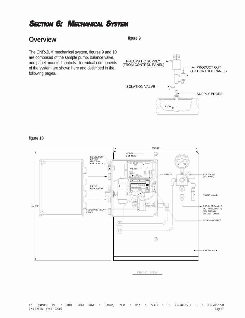
Overview
The CNR-2LM mechanical system, figures 9 and 10are composed of the sample pump, balance valve,and panel mounted controls. Individual componentsof the system are shown here and described in thefollowing pages.
figure 9
figure 10
ISOLATION VALVE
FLOW
SUPPLY PROBE
(FROM CONTROL PANEL)PNEUMATIC SUPPLY
(TO CONTROL PANEL)PRODUCT OUT
VALVEPNEUMATIC RELAY
19 7/8"
PIM-100
PSI
Z-65 TIMERMODEL
Factory
ApprovedSystem
REGULATORFILTER
CABLE ENTRY)(7/16" Max.
LIQUID TIGHTFITTING
Pulse Input Module
4096
Input Adj.
32
PIM-100
21 4 8 16
512
256
12864
1024
2048
Mutual
IG 1
-SIG 2
655
36
163
8481
92
327
68
13
1072
PO
WE
R2
621
44
Red-1
White-3
Black-5
15 3/8"
RELIEF VALVE
SOLENOID VALVE
(1/8" TUBING)OUT TO DURASITEPRODUCT SAMPLE
VESSEL RACK
(BY CUSTOMER)
(1/4" FNPT)ROB VALVE
1000
500
psi
1500
2000

YZ Systems, Inc. • 3101 Pollok Drive • Conroe, Texas • USA • 77303 • P: 936.788.5593 • F: 936.788.5720Page 18 CNR-LM-6M ver.01122005
SSSSSECTIONECTIONECTIONECTIONECTION 6: 6: 6: 6: 6: M M M M MECHANICALECHANICALECHANICALECHANICALECHANICAL S S S S SYYYYYSTEMSTEMSTEMSTEMSTEM
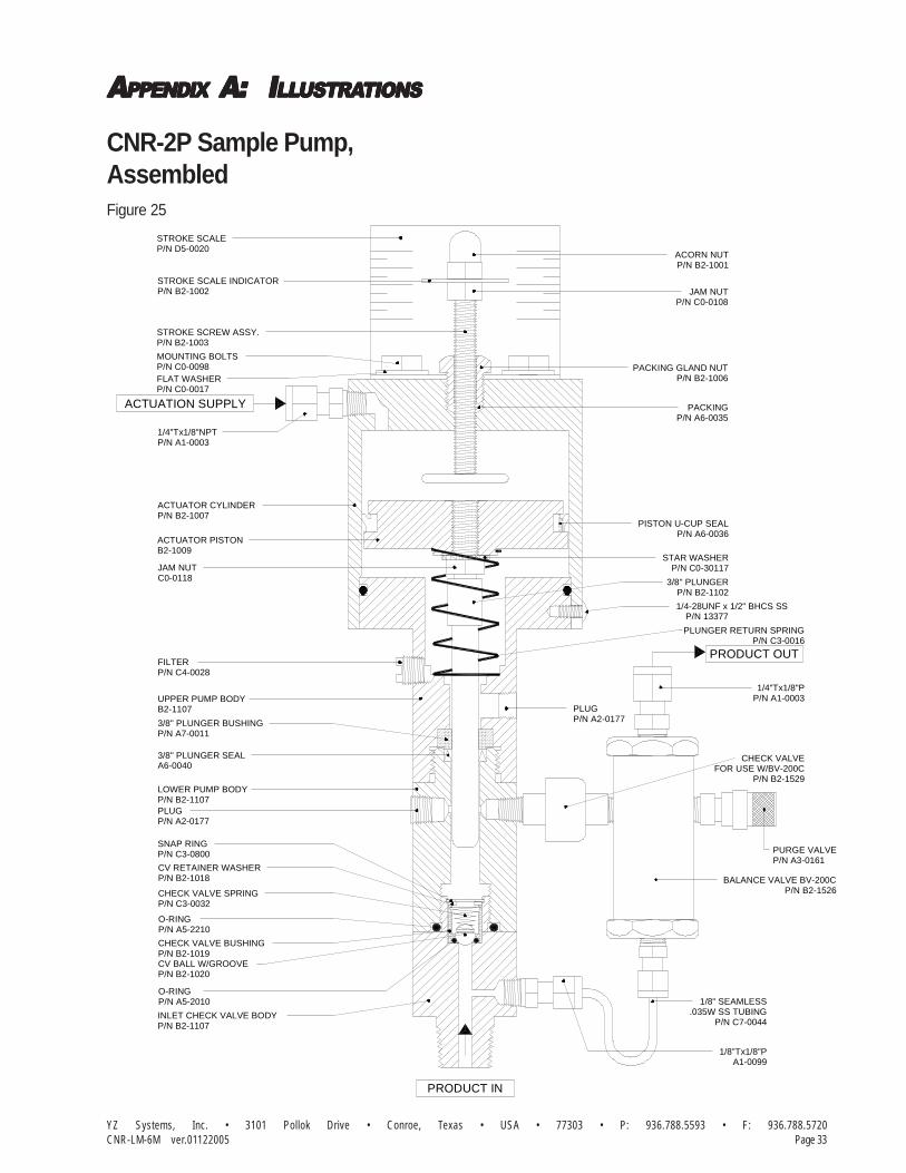
CNR-2P Sample Pump & Balance Valve
The CNR-2P Sample Pump, refer to AppendixA, page 33, is a positive displacement plungerpump designed to be mounted directly on thepipeline. It has an adjustable displacement of0.25 to 1.8cc and achieves proportional-to-flowsampling through adjustment of the systemelectronic control discussed in Section 4, page 11.
As the plunger returns upward after completing astroke, the pump chamber fills with productthrough the inlet check valve. The inlet checkvalve is a ball type check valve designed to seaton an o-ring. The inlet check valve is springloaded to ensure a positive seating action afterevery stroke. When the pump is actuated , theplunger moves downward, displacing productthrough the discharge check valve known as thebalance valve.
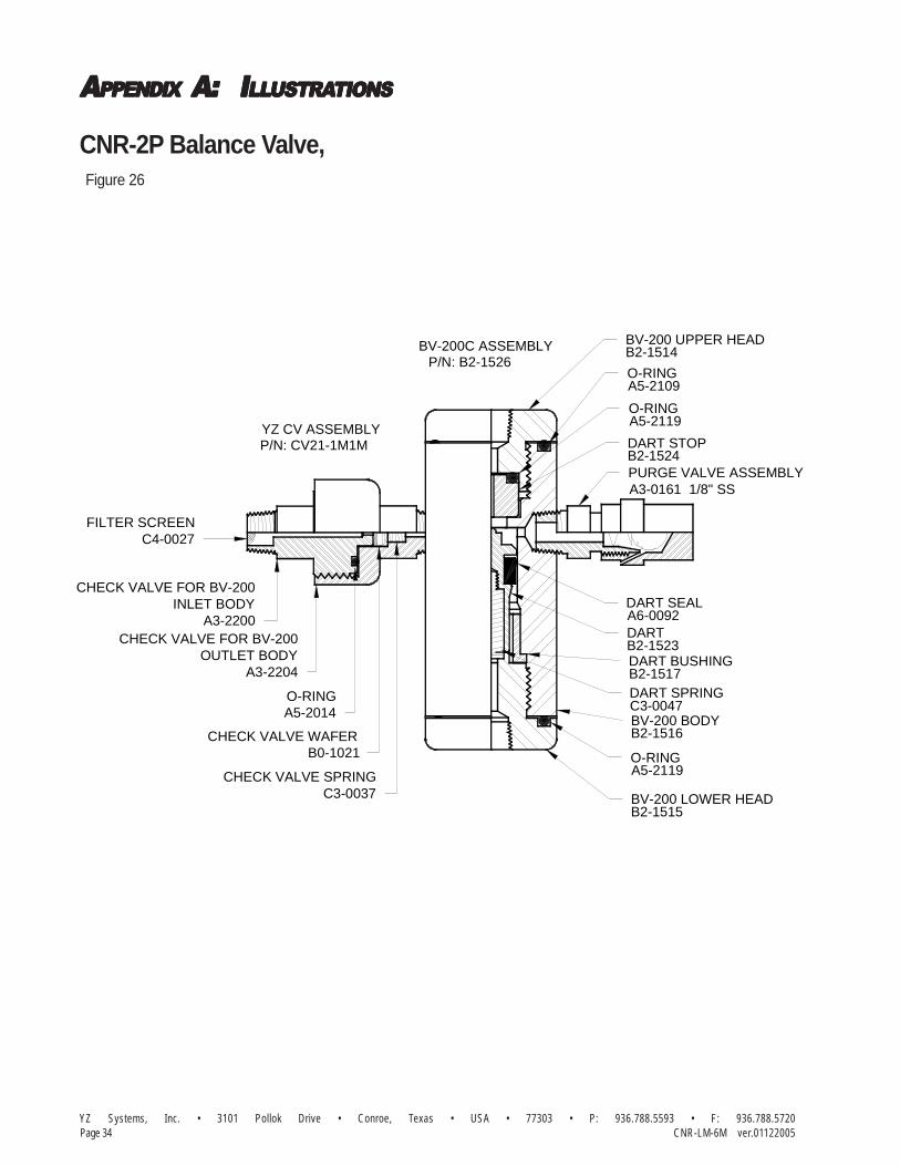
The Balance Valve, refer to Appendix A, page34, automatically senses pipeline pressure andadjusts to ensure that product is not allowed tofree flow to the product vessel. When thepipeline pressure is greater than the prechargepressure on the accumulator vessel, the balancevalve dart is pushed up against the seat and thetop head of the balance valve. As the pumpstrokes, the pressure created in the pumpchamber forces the balance valve dart off theseat, allowing product to be pumped to theDuraSite portable sample vessel. Once thepump completes its stroke, the pressure acrossthe balance valve equalizes and the dart isreturned to a sealing position by its spring.
In the event that the DuraSite portable samplevessel, precharge pressure is greater than thepipeline pressure, the balance valve dart andseat are pushed apart by the product pressure inthe DuraSite portable sample vessel. In thissituation the check valve wafer located betweenthe balance valve and the sample pump acts asa back check to prevent the escape of productpreviously captured in the DuraSite portable
sample vessel. As the pump strokes, the pres-sure created in the pump chamber forces thecheck valve wafer off the seat, allowing productto be pumped to the DuraSite portable samplevessel. Once the pump completes its stroke, thepressure across the check valve equalizes andthe wafer is returned to a sealing position by itsspring.
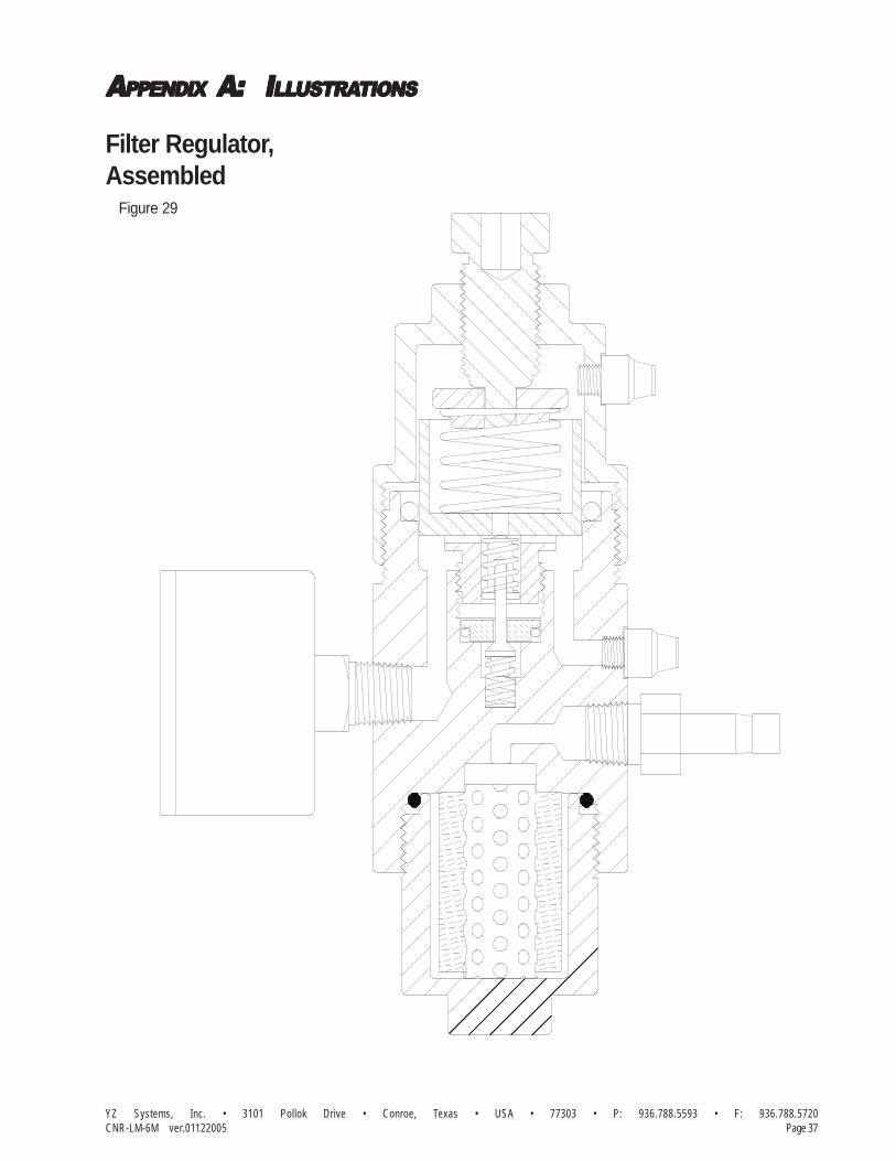
Filter Regulator
The YZ stainless steel Filter Regulator, refer toAppendix A, page 37, is capable of taking inputpressures of up to 1500 psi, and regulating to adischarge pressure of as low as 20 psi. Mosttypical installations will need a 30 psi dischargepressure setting. A debris filter is built into thebase of the filter regulator to assist in providing aclean supply of actuation gas to your low pow-ered solenoid, and pneumatic relay valve. Thisgas is ultimately used to provide the pneumaticactuation of the Sample Pump.
Pneumatic Relay
The YZ pneumatic relay, refer to Appendix A,page 39, works in conjunction with the lowpowered solenoid to provide the pneumaticactuation of the Sample Pump. The very lowpower available from the controller in the intrinsi-cally safe electrical environment, restricts thesize of solenoid that may be operated. The lowpowered solenoid provides a very low volume ofgas, which is not capable of stroking the samplepump, but works well as a pneumatic trigger forthe pneumatic relay. The pneumatic relay thenallows the pump to receive sufficient gas volumein a very short period of time to allow the pumpto make a complete stroke.

YZ Systems, Inc. • 3101 Pollok Drive • Conroe, Texas • USA • 77303 • P: 936.788.5593 • F: 936.788.5720Page 19CNR-LM-6M ver.01122005
SSSSSECTIONECTIONECTIONECTIONECTION 6: 6: 6: 6: 6: M M M M MECHANICALECHANICALECHANICALECHANICALECHANICAL S S S S SYYYYYSTEMSTEMSTEMSTEMSTEM
5-Way Cross
The Five-way Cross Assembly, refer to Appen-dix A, page 35, is located on the front of thepanel and includes the following items: productinlet tubing fitting, pressure gauge, relief valve,rob valve, accumulator vessel isolation valve/discharge tubing fitting, and the five-way cross.
The pressure gauge is used during normaloperation to indicate the pressure within theaccumulator vessel. During start-up andtroubleshooting procedures it is used in conjunc-tion with the accumulator vessel isolation valveto check pump performance.
The YZ relief valve is a reseating type valvewhich is factory set to relieve at 1800 psi. Alsoincorporated into the relief valve design is apositive indication feature which indicates that ithas relieved. If the system reaches a pressuregreater than the relief valve setting, the resultingrelease of product pushes the black relief valveindicator outside the relief valve body. Thisinforms the system operator during his nextsystem check that an over pressure conditionhas occurred. The indicator is reset by pushingit back into the relief valve body.
The rob valve is a YZ needle valve which is usedto remove product from the accumulator vesselat the end of the sample period. This valve isnormally closed.
The accumulator vessel isolation valve is usedto isolate the accumulator vessel from the rest ofthe product carrying portion of the samplingsystem. This valve is normally open.

YZ Systems, Inc. • 3101 Pollok Drive • Conroe, Texas • USA • 77303 • P: 936.788.5593 • F: 936.788.5720Page 20 CNR-LM-6M ver.01122005
SSSSSECTIONECTIONECTIONECTIONECTION 6: 6: 6: 6: 6: M M M M MECHANICALECHANICALECHANICALECHANICALECHANICAL S S S S SYYYYYSTEMSTEMSTEMSTEMSTEM
DuraSite Portable Sample VesselThe DuraSite Portable Sample Vessel permits theuser to remove a liquid or gas hydrocarbon samplefrom a pipeline or a sampling device. This is ac-complished without changing the pressure of theproduct or exposing it to a contaminant fluid. Ifproperly used and maintained the DuraSite will pro-vide many years of safe, accurate and clean sam-pling.
Use: The DuraSite is a very safe device to use.As with any equipment dealing with flammableproducts, it is mandatory that a good, thorough op-erator training procedure be established prior to use.
Typical use of the cylinder would be as follows:
Step 1: (In The Lab) Connect a regulated inertgas supply to the pre-charge valve. The productvalve should be open. By carefully controlling thepre-charge valve and the regulator, the cylindercan be slowly charged with pre-charge gas (NOTE:This should be done slowly to prevent slammingthe piston down to the opposite end). The pres-sure on the pre-charge pressure gauge should bebrought to a reading of 10-50 psi above the ex-pected pressure of the product in the field . Closethe pre-charge valve and disconnect the gas sup-ply. Check the pre-charge valve, relief device, andthe pre-charge pressure gauge for leaks. Any leaksshould be stopped before continuing. The vesselshould be placed in a padded carrying case and madeready for field use.
STEP 2: DIRECT CONNECTION TO SAMPLER.2a: Connect the sampler discharge port to theproduct inlet port to the DuraSite using 1/8" stain-less steel tubing.
2b: Pre-charge the DuraSite as indicated in Step1, then install a pressure relief valve to the pre-charge port and open the pre-charge valve on theDuraSite. (The pressure relief valve should have arelief pressure setting of approximately 100 psi aboveline pressure.)
2c: Open the product inlet valve of the DuraSiteand the purge valve on the sampler. Next openthe purge valve on the product end of the Dur-aSite and allow product to purge all lines and con-nections out.
2d: Close purge valves and begin sample cycle.
2e: At the end of sample cycle, close product inletvalve on the DuraSite and remove the DuraSite. Packthe DuraSite in appropriate carrying case to meet D.O.T.guideline, with D.O.T. paperwork and transport to labfor analysis.
Step 3: (In The Lab)Prior to analysis, the product should be mixed. Thisis accomplished simply and efficiently by invertingthe cylinder end-over-end, causing the mixing ballto fall through the product. Approximately 10-12trips of the mixing ball through the product assuresa homogenous solution.
Step 4: Purging a small amount of product fromthe vessel removes unmixed product from the tee,relief device, gauge, etc. The unit can now beconnected to a chromatograph and the productanalyzed.
Step 5: After analyzing, the remainder of the prod-uct should be dumped and the vessel properlycleaned. Normal cleaning can be accomplished byrinsing the product end with a petroleum solvent andflushing with acetone. If a more thorough cleaningis required, the vessel should be disassembled.
WARNING: A portable sample vessel should neverbe filled to more than 80%. This allows a 20%pre-charge cushion to absorb thermal expansionof the product.Shipping: Extreme care should be taken whenpreparing a vessel for shipment. Both valvesshould be capped to prevent possible leakage. Thevessel should be placed in a snug-fitting, well-pad-ded and durable case. All applicable DOT regula-tions should be adhered to.
YZ Systems, Inc. • 3101 Pollok Drive • Conroe, Texas • USA • 77303 • P: 936.788.5593 • F: 936.788.5720Page 21CNR-LM-6M ver.01122005
SSSSSECTIONECTIONECTIONECTIONECTION 7: 7: 7: 7: 7: S S S S SYYYYYSTEMSTEMSTEMSTEMSTEM O O O O OPERAPERAPERAPERAPERATIONTIONTIONTIONTION
Preparing The System for Operation
Sample Pump PrimingBefore the pump begins normal operation afterinitial installation or maintenance, the samplepump must be purged of all air in the samplechamber. The purge valve on the SamplePump/Balance Valve, refer to Apendix A, page 33,is used to evacuate the air from the chamberand to make sure the pump is liquid-packed. Ifthe pump is not purged before being placed intooperation, it will not function properly.
To purge the pump, open the purge valve lo-cated on the side of the CNR-2 Sample Pump/Balance Valve assembly. The product supplyvalve can then be opened to allow pipelineproduct to purge the air within the pump. Onceproduct begins exiting the purge valve, close thepurge valve. The sample pump is now ready tobegin operation.
Product Line TestClose the isolation valve located on the bottomof the Five-way Cross Assembly, refer toApendix A, page 35. Stroke the sample pumpuntil the system pressure reaches 1800 psi onthe Five-way Cross Assembly Gauge. Thepressure should hold steady between pumpstrokes. Once the system is at 1800 psi, leaktest all connections. Once the system has beentested, open the isolation valve located on thebottom of the Five-way Cross Assembly.
Sample Vessel ConnectionConnect a constant pressure portable samplevessel (DuraSite) to the product sample toDurasite connection on the bottom of the 5-wayCross Assembly, refer to Apendix A, page 35using a short section of 1/8" or 1/4" stainlesssteel tubing. The portable sample vessel mustalso be precharged to 100-150 psi above thevapor pressure of the product, and a pressurerelief valve installed, on the pre-charge end ofthe DuraSite, refer to page 36. Open the Dur-aSite product valve, pre-charge valve, and theisolation valve on the bottom of the 5-way crossassembly.

YZ Systems, Inc. • 3101 Pollok Drive • Conroe, Texas • USA • 77303 • P: 936.788.5593 • F: 936.788.5720Page 22 CNR-LM-6M ver.01122005
SSSSSECTIONECTIONECTIONECTIONECTION 7: 7: 7: 7: 7: S S S S SYYYYYSTEMSTEMSTEMSTEMSTEM O O O O OPERAPERAPERAPERAPERATIONTIONTIONTIONTION
Notes
YZ Systems, Inc. • 3101 Pollok Drive • Conroe, Texas • USA • 77303 • P: 936.788.5593 • F: 936.788.5720Page 23CNR-LM-6M ver.01122005
SSSSSECTIONECTIONECTIONECTIONECTION 8: 8: 8: 8: 8: S S S S SYYYYYSTEMSTEMSTEMSTEMSTEM M M M M MAINTENAINTENAINTENAINTENAINTENANCEANCEANCEANCEANCE
Preventative MaintenanceSchedule
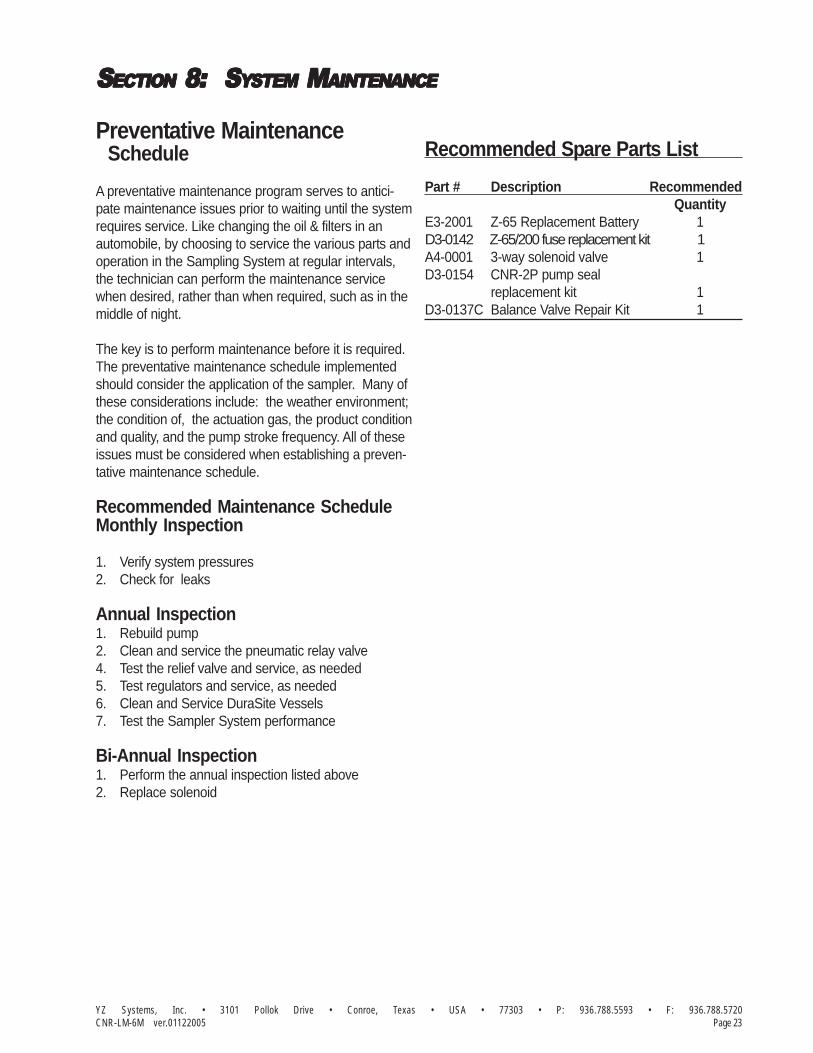
A preventative maintenance program serves to antici-pate maintenance issues prior to waiting until the systemrequires service. Like changing the oil & filters in anautomobile, by choosing to service the various parts andoperation in the Sampling System at regular intervals,the technician can perform the maintenance servicewhen desired, rather than when required, such as in themiddle of night.
The key is to perform maintenance before it is required.The preventative maintenance schedule implementedshould consider the application of the sampler. Many ofthese considerations include: the weather environment;the condition of, the actuation gas, the product conditionand quality, and the pump stroke frequency. All of theseissues must be considered when establishing a preven-tative maintenance schedule.
Recommended Maintenance ScheduleMonthly Inspection
1. Verify system pressures2. Check for leaks
Annual Inspection1. Rebuild pump2. Clean and service the pneumatic relay valve4. Test the relief valve and service, as needed5. Test regulators and service, as needed6. Clean and Service DuraSite Vessels7. Test the Sampler System performance
Bi-Annual Inspection1. Perform the annual inspection listed above2. Replace solenoid
Recommended Spare Parts List
Part # Description RecommendedQuantity
E3-2001 Z-65 Replacement Battery 1D3-0142 Z-65/200 fuse replacement kit 1A4-0001 3-way solenoid valve 1D3-0154 CNR-2P pump seal
replacement kit 1D3-0137C Balance Valve Repair Kit 1
YZ Systems, Inc. • 3101 Pollok Drive • Conroe, Texas • USA • 77303 • P: 936.788.5593 • F: 936.788.5720Page 24 CNR-LM-6M ver.01122005
SSSSSECTIONECTIONECTIONECTIONECTION 8: 8: 8: 8: 8: S S S S SYYYYYSTEMSTEMSTEMSTEMSTEM M M M M MAINTENAINTENAINTENAINTENAINTENANCEANCEANCEANCEANCE
Notes

YZ Systems, Inc. • 3101 Pollok Drive • Conroe, Texas • USA • 77303 • P: 936.788.5593 • F: 936.788.5720Page 25CNR-LM-6M ver.03072002
SSSSSECTIONECTIONECTIONECTIONECTION 9: 9: 9: 9: 9: S S S S SYYYYYSTEMSTEMSTEMSTEMSTEM TTTTTRRRRROUBLESHOOOUBLESHOOOUBLESHOOOUBLESHOOOUBLESHOOTINGTINGTINGTINGTING
How to Use This Section
The recommendations contained in this section should beused as a preliminary information resource to remedy opera-tional issues with the CNR-2LM Sampling System. It isimportant to read all of the definitions and notes prior to initiatingwork.
Each subsection contains a description of the indicatorsfollowed by a step-by-step trouble shooting procedure.
For Additional Help
Any issue that can not be resolved through the use ofthis reference, please contact YZ Technical Service at:
T: 1.800.653.9435T: 1.936.788.5526, International CallsF: 1.936.788.5720Em: [email protected]
SAFETY NOSAFETY NOSAFETY NOSAFETY NOSAFETY NOTESTESTESTESTES• Always use extreme care when performing mainte-
nance on Sampling Systems. Always take necessarymeasures to assure that electrical classification in thearea is considered, before, and during all repairs, andthat necessary steps are taken to maintain properelectrical procedures for the classification of the area.
• Take special care when disconnecting any fitting, toassure that product and/or pressure will not bereleased when the connection is broken. This systemmay contain liquid and/or gas at high pressures.
Step-by-Step Resolution
Using a step-by-step method to resolve issues on theSampling System will reduce maintenance time andassist in returning the system to service quicker.
The following represent the recommended chronology toresolve issues:
Resolve issues to the following order:a. Actuation Gas System, page 26b. Controller Electrical Power, page 26c. Controller Counter Mode, page 27d. Controller Timer Mode, page 30e. Pump, page 31
YZ Systems, Inc. • 3101 Pollok Drive • Conroe, Texas • USA • 77303 • P: 936.788.5593 • F: 936.788.5720Page 26 CNR-LM-6M ver.03072002
SSSSSECTIONECTIONECTIONECTIONECTION 9: 9: 9: 9: 9: S S S S SYYYYYSTEMSTEMSTEMSTEMSTEM TTTTTRRRRROUBLESHOOOUBLESHOOOUBLESHOOOUBLESHOOOUBLESHOOTINGTINGTINGTINGTING
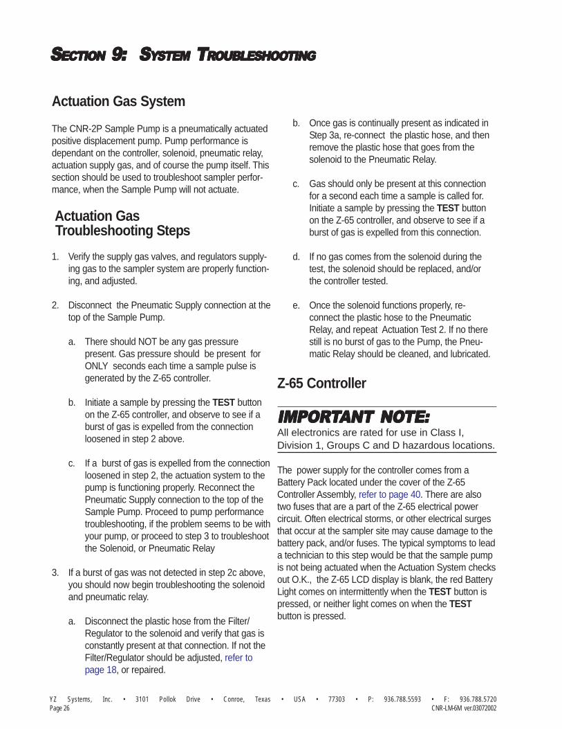
Actuation Gas System
The CNR-2P Sample Pump is a pneumatically actuatedpositive displacement pump. Pump performance isdependant on the controller, solenoid, pneumatic relay,actuation supply gas, and of course the pump itself. Thissection should be used to troubleshoot sampler perfor-mance, when the Sample Pump will not actuate.
Actuation Gas Troubleshooting Steps
1. Verify the supply gas valves, and regulators supply-ing gas to the sampler system are properly function-ing, and adjusted.
2. Disconnect the Pneumatic Supply connection at thetop of the Sample Pump.
a. There should NOT be any gas pressurepresent. Gas pressure should be present forONLY seconds each time a sample pulse isgenerated by the Z-65 controller.
b. Initiate a sample by pressing the TEST buttonon the Z-65 controller, and observe to see if aburst of gas is expelled from the connectionloosened in step 2 above.
c. If a burst of gas is expelled from the connectionloosened in step 2, the actuation system to thepump is functioning properly. Reconnect thePneumatic Supply connection to the top of theSample Pump. Proceed to pump performancetroubleshooting, if the problem seems to be withyour pump, or proceed to step 3 to troubleshootthe Solenoid, or Pneumatic Relay
3. If a burst of gas was not detected in step 2c above,you should now begin troubleshooting the solenoidand pneumatic relay.
a. Disconnect the plastic hose from the Filter/Regulator to the solenoid and verify that gas isconstantly present at that connection. If not theFilter/Regulator should be adjusted, refer topage 18, or repaired.
Z-65 Controller
IMPORIMPORIMPORIMPORIMPORTTTTTANT NOANT NOANT NOANT NOANT NOTE:TE:TE:TE:TE:All electronics are rated for use in Class I,Division 1, Groups C and D hazardous locations.
The power supply for the controller comes from aBattery Pack located under the cover of the Z-65Controller Assembly, refer to page 40. There are alsotwo fuses that are a part of the Z-65 electrical powercircuit. Often electrical storms, or other electrical surgesthat occur at the sampler site may cause damage to thebattery pack, and/or fuses. The typical symptoms to leada technician to this step would be that the sample pumpis not being actuated when the Actuation System checksout O.K., the Z-65 LCD display is blank, the red BatteryLight comes on intermittently when the TEST button ispressed, or neither light comes on when the TESTbutton is pressed.
b. Once gas is continually present as indicated inStep 3a, re-connect the plastic hose, and thenremove the plastic hose that goes from thesolenoid to the Pneumatic Relay.
c. Gas should only be present at this connectionfor a second each time a sample is called for.Initiate a sample by pressing the TEST buttonon the Z-65 controller, and observe to see if aburst of gas is expelled from this connection.
d. If no gas comes from the solenoid during thetest, the solenoid should be replaced, and/orthe controller tested.
e. Once the solenoid functions properly, re-connect the plastic hose to the PneumaticRelay, and repeat Actuation Test 2. If no therestill is no burst of gas to the Pump, the Pneu-matic Relay should be cleaned, and lubricated.

YZ Systems, Inc. • 3101 Pollok Drive • Conroe, Texas • USA • 77303 • P: 936.788.5593 • F: 936.788.5720Page 27CNR-LM-6M ver.03072002
SSSSSECTIONECTIONECTIONECTIONECTION 9: 9: 9: 9: 9: S S S S SYYYYYSTEMSTEMSTEMSTEMSTEM TTTTTRRRRROUBLESHOOOUBLESHOOOUBLESHOOOUBLESHOOOUBLESHOOTINGTINGTINGTINGTING
Controller Electrical Power Troubleshooting Steps
1. Battery Test:
a. Set the mode switches as follows:Mode Switch Position 1, 2 and 3 ON.
b. Set the time switches to the 01 posi-tion. This will set the solenoid outputrate to one actuation every one minute(based on the factory set time range forthe Z-65 model).
NONONONONOTE:TE:TE:TE:TE:• Time switches must not be in 00 position to test the
battery.• The solenoid must be connected to test the battery
condition. Battery condition cannot be testedwith a volt meter.
c. Depress the test switch to test thebattery. A green LED will illuminate ifthe battery is good and a red LED willilluminate if the battery is low.
2. Replacing a Depleted Battery:
a. Remove the four thumb screws, coverplate and orange terminal connector.
b. The battery is located in the lower lefthand corner of the Z-65 controllerassembly.
c. Unclip the battery plug from the batteryreceptacle.
d. Replace the depleted battery with a freshbattery pack (part No. E3-2001).
e. Return the mode switches to theiroriginal positions.
Battery Pack
NONONONONOTE:TE:TE:TE:TE:• Follow the illustration to assure proper battery wire
placement in the Z-65 enclosure.• Send your depleted battery to:
YZ Systems, Inc.206 Lubbock Hwy.Snyder, TX 79549 USA
figure 11
figure 12

YZ Systems, Inc. • 3101 Pollok Drive • Conroe, Texas • USA • 77303 • P: 936.788.5593 • F: 936.788.5720Page 28 CNR-LM-6M ver.03072002
SSSSSECTIONECTIONECTIONECTIONECTION 9: 9: 9: 9: 9: S S S S SYYYYYSTEMSTEMSTEMSTEMSTEM TTTTTRRRRROUBLESHOOOUBLESHOOOUBLESHOOOUBLESHOOOUBLESHOOTINGTINGTINGTINGTING
Controller Counter Mode Troubleshooting Steps
1. Input Pulse Test
a. Set the mode switches as follows: Position 1 and 3 ON, 2 and 4 OFF.
b. Set the count switches to 00 to enter the diagnostic mode. This mode enables the user to determine if the proper input pulses are being received at the count input (ter. #3).
2. Dry Contact Input: mode switch 4 should be in the off position. Depress the test switch and hold. A red LED should illuminate. When the dry contact input is received at the counter input (ter. #3) the green LED will turn on and off and the red LED will illuminate again. This will normally occur very quickly and give the appearance that the green LED blinks on when the pulse input is received and removed.
3. Voltage Pulse Input: move mode switch 4 to the on position. Depress the test switch and hold. A green LED should illuminate. When the voltage pulse input is received at the count input (ter. #3) the red LED will turn on and off and the green LED will illuminate again. This will normally occur very quickly and give the appearance that the red LED blinks on when the pulse input is received and removed.
dry contactopen collector(20 mSec duration min.) +
Ter. #5Ter. #3
-
voltage pulse-+
Ter. #5Ter. #3
5-24 VDC(20 mSec duration min.)
Factory
SystemApproved
Mutual
figure 13
figure 14
figure 15
figure 16

YZ Systems, Inc. • 3101 Pollok Drive • Conroe, Texas • USA • 77303 • P: 936.788.5593 • F: 936.788.5720Page 29CNR-LM-6M ver.03072002
SSSSSECTIONECTIONECTIONECTIONECTION 9: 9: 9: 9: 9: S S S S SYYYYYSTEMSTEMSTEMSTEMSTEM TTTTTRRRRROUBLESHOOOUBLESHOOOUBLESHOOOUBLESHOOOUBLESHOOTINGTINGTINGTINGTING
4. Mechanical Operation Test: a. Set the mode switches as follows:
Positions 1, 2 and 3 ON. Position 4 OFF.
b. Set the time switches to 00 to enter the diagnostic mode. This mode enables the user to increase the solenoid output rate to one pulse every two seconds.
5. LCD Stroke Indicator Test Mode: a. To test the stroke counter, set the mode switches as follows:
Positions 1, 2 and 3 ON. Position 4 OFF.
b. Set the time switches to 00.
c. Unscrew the thumbscrews and remove the six position terminal strip and cover. This will expose the battery pack and the three position configuration jumper (located in the lower right corner of the Z-65 controller assembly).
d. Set the configuration jumper to the far right position marked stroke indicator test.
e. This will cause all six digits to become active on the stroke counter. Depress the reset. The stroke counter should incre- ment 000000, 111111, etc., up to 999999 each time the solenoid fires. When the counter display reads 999999, the test is complete.
12.3 d - Jumper switch location
������Approved
Factory
System
Factory
Approved
MutualSystem
Factory
SystemApproved
Mutual
NONONONONOTE:TE:TE:TE:TE:• When the test is complete, move the jumper back to
the factory position (far left position)factory positioned
for 1 - 99 counts (xx)Jumper switch location
MutualSystemApproved
Factory
figure 17
figure 18
figure 19
figure 20
figure 21
figure 22

YZ Systems, Inc. • 3101 Pollok Drive • Conroe, Texas • USA • 77303 • P: 936.788.5593 • F: 936.788.5720Page 30 CNR-LM-6M ver.03072002
SSSSSECTIONECTIONECTIONECTIONECTION 9: 9: 9: 9: 9: S S S S SYYYYYSTEMSTEMSTEMSTEMSTEM TTTTTRRRRROUBLESHOOOUBLESHOOOUBLESHOOOUBLESHOOOUBLESHOOTINGTINGTINGTINGTING
6. Timer Range Setting There are two Z-65 models: the Z-65/6.1 and Z-65/6.03. Each Z-65 timer has two ranges for the timer setting dials.
a. Z-65/6.1 Range Setting: xx minutes: set the configuration jumper to the far left position (factory setting). x.x minutes: set the configuration jumper to the center position.
Note: To obtain maximum battery life, choose thelongest solenoid stroke rate possible.
b. Z-65/6.03 Range Setting: x.x minutes: set the configuration jumper to the far left position (factory setting). .xx minutes: set the configuration jumper to the center position.
Note: To obtain maximum battery life, choose thelongest solenoid stroke rate possible.
MutualSystemApproved
Factory
factory positionedfor .1 - 9.9 counts (x.x)Jumper switch location
Jumper switch locationfor .03 - .99 counts (.xx)
MutualSystemApproved
Factory
Controller Timer Mode Troubleshooting Steps figure 23
figure 24

YZ Systems, Inc. • 3101 Pollok Drive • Conroe, Texas • USA • 77303 • P: 936.788.5593 • F: 936.788.5720Page 31CNR-LM-6M ver.03072002
SSSSSECTIONECTIONECTIONECTIONECTION 9: 9: 9: 9: 9: S S S S SYYYYYSTEMSTEMSTEMSTEMSTEM TTTTTRRRRROUBLESHOOOUBLESHOOOUBLESHOOOUBLESHOOOUBLESHOOTINGTINGTINGTINGTING
Pump Performance
There are many factors that affect pump performance.Some are within the pump, while others are outsidefactors that affect pump performance.
Pump Performance Troubleshooting Steps
1. Actual performance of the Actuation Gas, andElectrical Power issues should have already beendealt with, If not , perform those troubleshootingsteps before proceeding to step 2.
2. Close the isolation valve located on the bottom ofthe Five-way Cross Assembly. Stroke the samplepump while observing the pressure reading on theFive-way Cross Assembly Gauge. The systempressure should steadily build to 1800 psi . Thepressure should hold steady between pumpstrokes. Once the system is at 1800 psi, leak testall connections. Once the system has been tested,open the isolation valve located on the bottom ofthe Five-way Cross Assembly. Completion of thistest verifies the pump performance is O.K.
3. The next step, if the pump did not pass the test instep 2, is to verify that the pump is fully liquidpacked with liquid product to be pumped. TheSample Pump must be purged of all air in thesample chamber, before it can pump liquid product.The purge valve on the sample pump is used toevacuate the air from the chamber and to makesure the pump is liquid-packed. If the pump is notpurged properly, it will not function properly.
a. Open the purge valve located on the left side ofthe CNR-2 sample pump.
b. Next open the product supply valve to allowpipeline product to purge the air within thepump.
c. Once product begins exiting the purge valve,close the purge valve. The sample pump isnow ready to begin operation. Perform pumptest #2 again. If your product is not consistentlyin a single phase liquid state the pump willvapor lock again, and repriming will be neces-sary, repeatedly, till the phase condition of theproduct is resolved.
4. If during the pump troubleshooting step 2, youobserved the pressure on the Five-way CrossAssembly Gauge jumping from pipeline pressure toa higher pressure, during the pump stroke, butimmediately returning to pipeline pressure after thestroke, the Balance Valve Assembly should berebuilt using a YZ Repair Kit P/N D3-0137C.
5. If during the pump troubleshooting step 2, youobserved the pressure on the Five-way CrossAssembly Gauge build steadily to pipeline pressure,then stop building at pipeline pressure, the SamplePump inlet check is not holding. Typically installing aYZ Repair Kit P/N D3-0154, will resolve this situa-tion.
YZ Systems, Inc. • 3101 Pollok Drive • Conroe, Texas • USA • 77303 • P: 936.788.5593 • F: 936.788.5720Page 32 CNR-LM-6M ver.03072002
SSSSSECTIONECTIONECTIONECTIONECTION 9: 9: 9: 9: 9: S S S S SYYYYYSTEMSTEMSTEMSTEMSTEM TTTTTRRRRROUBLESHOOOUBLESHOOOUBLESHOOOUBLESHOOOUBLESHOOTINGTINGTINGTINGTING
Notes
YZ Systems, Inc. • 3101 Pollok Drive • Conroe, Texas • USA • 77303 • P: 936.788.5593 • F: 936.788.5720Page 33CNR-LM-6M ver.01122005
AAAAAPPENDIXPPENDIXPPENDIXPPENDIXPPENDIX A: A: A: A: A: IIIIILLLLLLLLLLUSTRAUSTRAUSTRAUSTRAUSTRATIONSTIONSTIONSTIONSTIONS
CNR-2P Sample Pump,AssembledFigure 25
O-RING
O-RING
P/N A5-2210
CV BALL W/GROOVEP/N B2-1020
P/N A5-2010
P/N B2-1107
P/N B2-1019
INLET CHECK VALVE BODY
CHECK VALVE BUSHING
FILTER
A6-0040
UPPER PUMP BODYB2-1107
P/N A7-0011
3/8" PLUNGER SEAL
P/N C4-0028
PLUGP/N B2-1107LOWER PUMP BODY
P/N A2-0177
SNAP RINGP/N C3-0800
P/N B2-1018
P/N C3-0032
3/8" PLUNGER BUSHING
CV RETAINER WASHER
CHECK VALVE SPRING
FLAT WASHER
1/4"Tx1/8"NPTP/N A1-0003
P/N C0-0017
B2-1009
C0-0118
ACTUATOR PISTON
JAM NUT
P/N B2-1007
ACTUATION SUPPLY
ACTUATOR CYLINDER
STROKE SCALE
P/N B2-1002
P/N B2-1003
MOUNTING BOLTSP/N C0-0098
P/N D5-0020
STROKE SCALE INDICATOR
STROKE SCREW ASSY.
PRODUCT OUT
PRODUCT IN
A1-00991/8"Tx1/8"P
P/N C7-0044.035W SS TUBING
1/8" SEAMLESS
PURGE VALVE
BALANCE VALVE BV-200CP/N B2-1526
P/N B2-1529
P/N A3-0161
CHECK VALVEFOR USE W/BV-200C
1/4"Tx1/8"PP/N A1-0003
3/8" PLUNGER
STAR WASHER
PISTON U-CUP SEAL
PACKING GLAND NUT
1/4-28UNF x 1/2" BHCS SS
PLUNGER RETURN SPRING
P/N B2-1102
P/N 13377
P/N A6-0036
P/N C0-30117
P/N C3-0016
P/N A6-0035PACKING
ACORN NUT
P/N B2-1006
P/N C0-0108JAM NUT
P/N B2-1001
PLUGP/N A2-0177
YZ Systems, Inc. • 3101 Pollok Drive • Conroe, Texas • USA • 77303 • P: 936.788.5593 • F: 936.788.5720Page 34 CNR-LM-6M ver.01122005
AAAAAPPENDIXPPENDIXPPENDIXPPENDIXPPENDIX A: A: A: A: A: IIIIILLLLLLLLLLUSTRAUSTRAUSTRAUSTRAUSTRATIONSTIONSTIONSTIONSTIONS
CNR-2P Balance Valve, Figure 26
O-RING
DART STOP
PURGE VALVE ASSEMBLYA3-0161 1/8" SS
DART SEAL
DART
DART SPRING
O-RING
BV-200 LOWER HEAD
P/N: B2-1526BV-200C ASSEMBLY
YZ CV ASSEMBLYP/N: CV21-1M1M
DART BUSHING
BV-200 BODY
O-RING
BV-200 UPPER HEADB2-1514
A5-2109
A5-2119
B2-1524
A6-0092
B2-1523
B2-1517
C3-0047
B2-1516
B2-1515
A5-2119
FILTER SCREENC4-0027
CHECK VALVE FOR BV-200INLET BODY
A3-2200CHECK VALVE FOR BV-200
OUTLET BODYA3-2204
O-RINGA5-2014
CHECK VALVE WAFERB0-1021
CHECK VALVE SPRINGC3-0037

YZ Systems, Inc. • 3101 Pollok Drive • Conroe, Texas • USA • 77303 • P: 936.788.5593 • F: 936.788.5720Page 35CNR-LM-6M ver.01122005
AAAAAPPENDIXPPENDIXPPENDIXPPENDIXPPENDIX A: A: A: A: A: IIIIILLLLLLLLLLUSTRAUSTRAUSTRAUSTRAUSTRATIONSTIONSTIONSTIONSTIONS
1000
5-Way CrossBody
To ProductAccumulator Vessel
psi2000
1500500
PressureGauge
Product Removal Valve(1/4" FNPT Connection)
Product Accumulator VesselIsolation Valve
Relief Valve(1800 PSI)
From Sample Pump
5-Way Cross Assembly, Figure 27

YZ Systems, Inc. • 3101 Pollok Drive • Conroe, Texas • USA • 77303 • P: 936.788.5593 • F: 936.788.5720Page 36 CNR-LM-6M ver.01122005
AAAAAPPENDIXPPENDIXPPENDIXPPENDIXPPENDIX A: A: A: A: A: IIIIILLLLLLLLLLUSTRAUSTRAUSTRAUSTRAUSTRATIONSTIONSTIONSTIONSTIONS
DuraSite, Figure 28
Seat Retaining Washer
P/N A6-0023
P/N A3-0347
Pre-Charge HeadYZ UniValve
P/N C6-1001
P/N A3-0156Rupture Disc
P/N C6-1500 (DS-800)
Rupture Disc Nut
P/N C6-1201 (DS-150)
P/N C6-1601 (DS-1000)P/N C6-1501 (DS-800)P/N C6-1401 (DS-500)P/N C6-1301 (DS-300)
P/N C6-1600 (DS-1000)
Tie Rod
P/N C6-1400 (DS-500)P/N C6-1300 (DS-300)P/N C6-1200 (DS-150)
P/N C3-0901
Cylinder
O-RingP/N A5-1021
Snap Ring
Valve SeatP/N A3-0063
P/N A3-0062
P/N C6-1005Mixing Ball
Piston Seal
O-RingP/N A5-1222
Stainless Steel
Back-Up WasherP/N A5-4222B
Hex NutsP/N C0-0048
P/N C6-1000Product HeadYZ UniValve
Purge Valve NutP/N A3-0080
P/N A3-0063Valve Seat
P/N C6-1003 (Ser. #4608+)
P/N 12-1006 (Ser. #0321 and Prior)P/N 12-1007 (Ser. #0322 - #0613)P/N 12-1008 (Ser. #0614 - #4087)P/N C6-1002 (Ser. #4088+)
Piston WasherP/N C6-1004
Piston
P/N 12-1018 (Ser. #0613 and Prior)P/N 12-1019 (Ser. #0614 - #4607)
Magnetic Volume Indicator
Gauge
P/N C6-1603 (DS-1000)P/N C6-1503 (DS-800)P/N C6-1403 (DS-500)P/N C6-1303 (DS-300)P/N C6-1203 (DS-150)
P/N A8-0036
Magnet Assembly
O-Ring Bonnet AssemblyP/N A3-0095
Knob (Black)P/N A3-0251
Set ScrewC0-0099
YZ Systems, Inc. • 3101 Pollok Drive • Conroe, Texas • USA • 77303 • P: 936.788.5593 • F: 936.788.5720Page 37CNR-LM-6M ver.01122005
AAAAAPPENDIXPPENDIXPPENDIXPPENDIXPPENDIX A: A: A: A: A: IIIIILLLLLLLLLLUSTRAUSTRAUSTRAUSTRAUSTRATIONSTIONSTIONSTIONSTIONS
Filter Regulator,Assembled
Figure 29

YZ Systems, Inc. • 3101 Pollok Drive • Conroe, Texas • USA • 77303 • P: 936.788.5593 • F: 936.788.5720Page 38 CNR-LM-6M ver.01122005
AAAAAPPENDIXPPENDIXPPENDIXPPENDIXPPENDIX A: A: A: A: A: IIIIILLLLLLLLLLUSTRAUSTRAUSTRAUSTRAUSTRATIONSTIONSTIONSTIONSTIONS
Figure 30
Filter Regulator,Exploded View
* Filter/Regulator Repair Kit P/N D3-0003
Pressure Gauge
P/N C3-0009
P/N C3-0011Lower Spring
Lower Dart *A3-0073
O-Ring (012) *
Retaining Nut
P/N A5-1012
Seat *P/N A3-0072
Upper Dart *P/N A3-0071
Upper SpringP/N C3-0010
P/N A3-0070
PistonP/N A3-0069
Piston Spring
Spring CapP/N A3-0068
P/N A3-0067Bonnet
PneumaticFittingP/N A1-0113
P/N A8-0016
Adjustment ScrewP/N A3-0066
O-Ring (120) *
Filter HousingP/N A3-0076
Filter Element *P/N C4-0004
Filter TubeP/N C4-0003
P/N A5-1120
P/N A3-0074Body
Tubing FittingP/N A1-0117
Pneumatic
P/N A1-0113Fitting
O-Ring (214) *P/N A5-1214

YZ Systems, Inc. • 3101 Pollok Drive • Conroe, Texas • USA • 77303 • P: 936.788.5593 • F: 936.788.5720Page 39CNR-LM-6M ver.01122005
AAAAAPPENDIXPPENDIXPPENDIXPPENDIXPPENDIX A: A: A: A: A: IIIIILLLLLLLLLLUSTRAUSTRAUSTRAUSTRAUSTRATIONSTIONSTIONSTIONSTIONS
Pneumatic Relay,Figure 31
PNEUMATIC RELAY TOP PLUG
PNEUMATIC RELAY PISTON
PNEUMATIC RELAY BOTTOM PLUG
PNEUMATIC RELAY PUSHROD
BILL OF MATERIALS
PNEUMATIC RELAY BODY
'K' SEAL, 1" #KP-125-01.000 C-44 ACT.
NJEX RELAY VALVE WAFER
7 A3-0291
FV-3 SPRING
OR -016 NITRILE9
8
11
12
13
10
A5-2016
B0-0113
C3-0048
A6-0099
B0-0115
A1-0236 MELBOW 5/32T x #10-32
DESCRIPTION
OR -020 NITRILE
REF.
1
2
4
3
B0-0112
A5-2020
B0-0111
C0-0350
PART NO.
6 A6-0113
5 B0-0074 CV WAFER - 1/2" STD.
10-32 HEX NY-LOCK NUT
1
1
1
1
1
1
1
1
1
1
1
QTY.
1
1

YZ Systems, Inc. • 3101 Pollok Drive • Conroe, Texas • USA • 77303 • P: 936.788.5593 • F: 936.788.5720Page 40 CNR-LM-6M ver.01122005
AAAAAPPENDIXPPENDIXPPENDIXPPENDIXPPENDIX A: A: A: A: A: IIIIILLLLLLLLLLUSTRAUSTRAUSTRAUSTRAUSTRATIONSTIONSTIONSTIONSTIONS
Electronic -6 Control,
3
8
4
7
6
1
10
5
9
2
Repair Kit* D3-0005 112 Z-65/200 Fuse Replacement Kit D3-0142 1
12
(2 Fuses Per Kit)
Ref. No. Description Part No. Qty.
Z-65/6 Controller Assembly1 1Model Z-65/6.1 F2-0001Model Z-65/6.03 F2-0018
2 Battery Pack E3-2001 13* Stroke Counter Assembly G1-0001 14* Terminal Strip, 6 Position H1-0001 15* BCD Switch E1-0001 26* Mode Switch E1-0002 17 Face Plate 1
Model Z-65/6.1 A9-3001Model Z-65/6.03 A9-3029
8 Thumb Screw A9-1001 49 Cable Assembly G2-0001 1
10 Solenoid Valve A4-0001 111
Figure 32
YZ Systems, Inc. • 3101 Pollok Drive • Conroe, Texas • USA • 77303 • P: 936.788.5593 • F: 936.788.5720Page 41CNR-LM-6M ver.01122005
AAAAAPPENDIXPPENDIXPPENDIXPPENDIXPPENDIX A: A: A: A: A: IIIIILLLLLLLLLLUSTRAUSTRAUSTRAUSTRAUSTRATIONSTIONSTIONSTIONSTIONS
Electronic Wiring Control Document,Figure 33
System Installation Notes and Recommendations

Notes:


3101 Pollok Drive
Conroe, Texas 77303
800.653.9435
P: 936.788.5593
F: 936.788.5698
Web: www.yzsystems.com
YZ Systems, Inc. represents and warrants that for a period of 1 year from receipt of the product: (1) the product will be free from defects in materials and workmanship; and (2)the product will perform substantially in accordance with product manuals, literature, or documentation. Any written or oral information or advice given by YZ representatives,agents, or employees will in no way increase the scope of this warranty. If the product fails to comply with the warranty set forth herein, YZ's entire liability and the customer'sexclusive remedy will be replacement of the product(s) or, at YZ's option, YZ's reasonable effort to make the product meet the warranty set forth herein. YZ disclaims all otherwarranties, either expressed or implied, including but not limited to, implied warranties or merchantability and fitness for a particular purpose, with respect to the product.This limited warranty gives you specific legal rights. You may have others, which vary from state to state. These remedies are not available outside of the United States andCanada. In no event shall YZ or its suppliers be liable for any damages whatsoever (including, without limitation, damages for loss of profits, business interruption, loss ofinformation, or other pecuniary loss) arising out of the use of or inability to use the product, even if YZ has been advised of the possibility of such damages. Information containedin this document is subject to change without notice and does not represent a commitment on the part of YZ Systems, Inc. All prices quoted are in U.S. dollars, F.O.B. Snyder, Texas.LINC, LINC Chemical Pumps, and LINC Level & Flow Switches are trademarks of YZ Systems, Inc. All other product names and/or registered trademarks are the property of theirrespective holders. YZ support services are subject to YZ's then-current prices, terms, and conditions, which are subject to change without notice. All prices and specifications, ifpublished, are subject to change without notice.
YZ Systems, Inc. represents and warrants that for a period of 3 years from receipt of the product: (1) the product will be free from defects in materials andworkmanship; and (2) the product will perform substantially in accordance with product manuals, literature, or documentation. Any written or oral information oradvice given by YZ representatives, agents, or employees will in no way increase the scope of this warranty. If the product fails to comply with the warrantyset forth herein, YZ's entire liability and the customer's exclusive remedy will be replacement of the product(s) or, at YZ's option, YZ's reasonable effort to makethe product meet the warranty set forth herein. YZ disclaims all other warranties, either expressed or implied, including but not limited to, impliedwarranties or merchantability and fitness for a particular purpose, with respect to the product. This limited warranty gives you specific legal rights.You may have others, which vary from state to state. These remedies are not available outside of the United States and Canada. In no event shall YZor its suppliers be liable for any damages whatsoever (including, without limitation, damages for loss of profits, business interruption, loss of information, or otherpecuniary loss) arising out of the use of or inability to use the product, even if YZ has been advised of the possibility of such damages. Information containedin this document is subject to change without notice and does not represent a commitment on the part of YZ Systems, Inc. All prices quoted are in U.S. dollars,F.O.B. Snyder, Texas. All other product names and/or registered trademarks are the property of their respective holders. YZ support services are subject toYZ's then-current prices, terms, and conditions, which are subject to change without notice. All prices and specifications, if published, are subject to changewithout notice.


