Cruise Plan for R/V Kilo Moana KM1116: ALOHA Cabled Observatory / Ka‘ena Ridge 24 April 2011 Version 0.2 Bruce Howe, Chief Scientist Department of Ocean and Resources Engineering School of Ocean and Earth Science and Technology University of Hawaii Department Office: 2540 Dole Street, Holmes Hall 402 Office: 1680 East-West Road, POST 105G Honolulu, HI 96822 Tel: 808-956-0466 Mobile: 808-469-0553 [email protected]Table of Contents 1. Introduction ................................................................................................................ 3 2. ALOHA Cabled Observatory.................................................................................... 4 3. Ka‘ena Ridge............................................................................................................. 10 4. Jason/Medea.............................................................................................................. 14 5. Navigation ................................................................................................................. 14 6. Deck Layout .............................................................................................................. 17 7. Mobilization .............................................................................................................. 19 8. Responsibilities ......................................................................................................... 20 9. Cruise Timeline......................................................................................................... 21 Appendix A – ACO Diagrams ........................................................................................ 22 Appendix B – ACO – Cable Termination Detail .......................................................... 24 Appendix C – ACO Operations ..................................................................................... 27 Appendix D – TAAM Mooring ...................................................................................... 33 Appendix E – Ka‘ena Ridge Operations ....................................................................... 35 Appendix F – Bathymetry in the ALOHA area............................................................ 36 Appendix G – Cruise Participants and Contacts List .................................................. 37 Appendix H – Berthing Plan .......................................................................................... 39 Appendix I – Acronyms and abbreviations .................................................................. 40
Transcript
Cruise Plan for R/V Kilo Moana KM1116: ALOHA Cabled Observatory / Ka‘ena Ridge
24 April 2011 Version 0.2
Bruce Howe, Chief Scientist
Department of Ocean and Resources Engineering School of Ocean and Earth Science and Technology
University of Hawaii Department Office: 2540 Dole Street, Holmes Hall 402
Office: 1680 East-West Road, POST 105G Honolulu, HI 96822
Table of Contents 1. Introduction ................................................................................................................3 2. ALOHA Cabled Observatory....................................................................................4 3. Ka‘ena Ridge.............................................................................................................10 4. Jason/Medea..............................................................................................................14 5. Navigation .................................................................................................................14 6. Deck Layout ..............................................................................................................17 7. Mobilization ..............................................................................................................19 8. Responsibilities .........................................................................................................20 9. Cruise Timeline.........................................................................................................21 Appendix A – ACO Diagrams........................................................................................22 Appendix B – ACO – Cable Termination Detail ..........................................................24 Appendix C – ACO Operations .....................................................................................27 Appendix D – TAAM Mooring ......................................................................................33 Appendix E – Ka‘ena Ridge Operations .......................................................................35 Appendix F – Bathymetry in the ALOHA area............................................................36 Appendix G – Cruise Participants and Contacts List..................................................37 Appendix H – Berthing Plan ..........................................................................................39 Appendix I – Acronyms and abbreviations ..................................................................40
List of Figures Figure 1-1 Map of area and nominal cruise lines. [inset of ALOHA] ........................................3 Figure 2-1 ACO – composite photo from October 2008.............................................................6 Figure 2-2 ACO seafloor layout ..................................................................................................6 Figure 2-3 ACO JBOX, top view................................................................................................7 Figure 2-4 JBOX side view showing ODI NRH connector (top left) .........................................7 Figure 2-5 OBS frame .................................................................................................................8 Figure 2-6 AMM seafloor secondary seafloor node ...................................................................8 Figure 2-7 Camera.......................................................................................................................9 Figure 2-8 TAAM anchor with cable spools...............................................................................9 Figure 2-9 The cable termination in 2008, with umbilical to the junction box...........................9 Figure 2-10 A snubber for additional in-line compliance .........................................................10 Figure 3-1 Bathymetry of Ka‘ena Ridge showing possible Jason dives (wiggly red lines) .....12 Figure 3-2 Approximate Geophysical Survey Lines (Ka‘ena Ridge) .......................................13 Figure 4-1 Jason ........................................................................................................................14 Figure 4-2 Medea ......................................................................................................................14 Figure 5-1 Sonardyne homer beacon.........................................................................................15 Figure 5-2 USBL transducer head.............................................................................................16 Figure 5-3 Octans inertial motion unit (left) and Moxa comms unit (right) .............................16 Figure 5-4 USBL mounting pictures .........................................................................................17 Figure 6-1 Main deck layout [Vic – need updated – HPU?].....................................................18 Figure 6-2 01 deck layout [Vic - need] .....................................................................................18 Figure A-1 ACO interconnection diagram................................................................................22 Figure A-2 ACO configuration, JBOX only .............................................................................23 Figure A-3 ACO configuration, JBOX and OBS......................................................................23 Figure B-1 ACO cable termination frame in Lab, top view......................................................24 Figure B-2 ACO cable termination frame in Lab, end-on view................................................25 Figure B-3 ACO cable termination frame in Lab, side view ....................................................26 Figure D-1 TAAM mooring diagram........................................................................................34 Figure D-2 TAAM thermistors..................................................................................................34 Figure D-3 TAAM fluorometer (FLNTU) ................................................................................34 Figure D-4 TAAM WHOI micro-modem .................................................................................34 Figure D-5 TAAM cable spacers ..............................................................................................34 Figure E-1 Locations of possible cables in the Ka‘ena Ridge region .......................................35 Figure F-1 Bathymetry around Station ALOHA (red star). Circles denote sill areas. ..............36
List of Tables Table 1-1 Coordinates of waypoints and stations ...........................................................................4 Table 3-1 Approximate Geophysical Survey Lines (Ka‘ena Ridge) ............................................14
1. Introduction The purpose of this NSF-funded cruise on the R/V Kilo Moana is twofold:
• Install the ALOHA Cabled Observatory (ACO) and,
• Survey portions of the Ka‘ena Ridge and collect rock samples. The remotely operated vehicle (ROV) Jason is essential to performing the required tasks.
The cruise is 18 days long, from 20 May to 7 June 2011. The ACO work is allocated 12 days, and the Ka‘ena Ridge 4 days. The ship will depart Honolulu at 0800 and proceed directly to Ka‘ena Ridge (the underwater extension of Oahu to the northwest) to conduct a Jason engineering dive, hopefully combining this with science work. Then we proceed to Station Aloha, 100 km north, to perform the ACO work. See Figure 1-1 for a map with nominal cruise lines. Table 1-1 gives coordinates of relevant points. The balance of the Ka‘ena Ridge work will come either at the end of the cruise, or, if there are problems with the ACO (e.g., bad weather), we will come back to Ka‘ena Ridge to work.
I’ll get to doing this soon with google earth…
Figure 1-1 Map of area and nominal cruise lines. [inset of ALOHA]
In this Plan, we first describe the ACO system and give an overview of the installation steps. This is followed by a description of the Ka‘ena Ridge work. The Jason / Medea system is described, including the navigation system. The ship and deck configuration is described followed by a (summary) timeline of operations and then a section on responsibilities. The very detailed, ACO step-by-step installation plan is given in Appendix C. Similarly, the details of the Ka‘ena Ridge work are given in Appendix C. Other appendices have information on the ACO cable termination, possible bathymetry mapping locations if time permits, personnel/contacts, berthing, and acronyms.
2. ALOHA Cabled Observatory The ACO is a prototypical example of a deep ocean observatory system that uses a retired cable. The ACO architecture uses highly reliable existing transoceanic cable systems to provide power and communications bandwidth. Since the cable is already in-place and is designed to operate for well beyond its commercial lifetime, costs of conversion to scientific use (as here) are substantially lower than for new systems. In the simplest terms, we want to provide power and communications ports for users to plug into on the seafloor for arbitrary instrumentation. Here, in addition we include sensors for scientific measurements of water properties, video and acoustics.
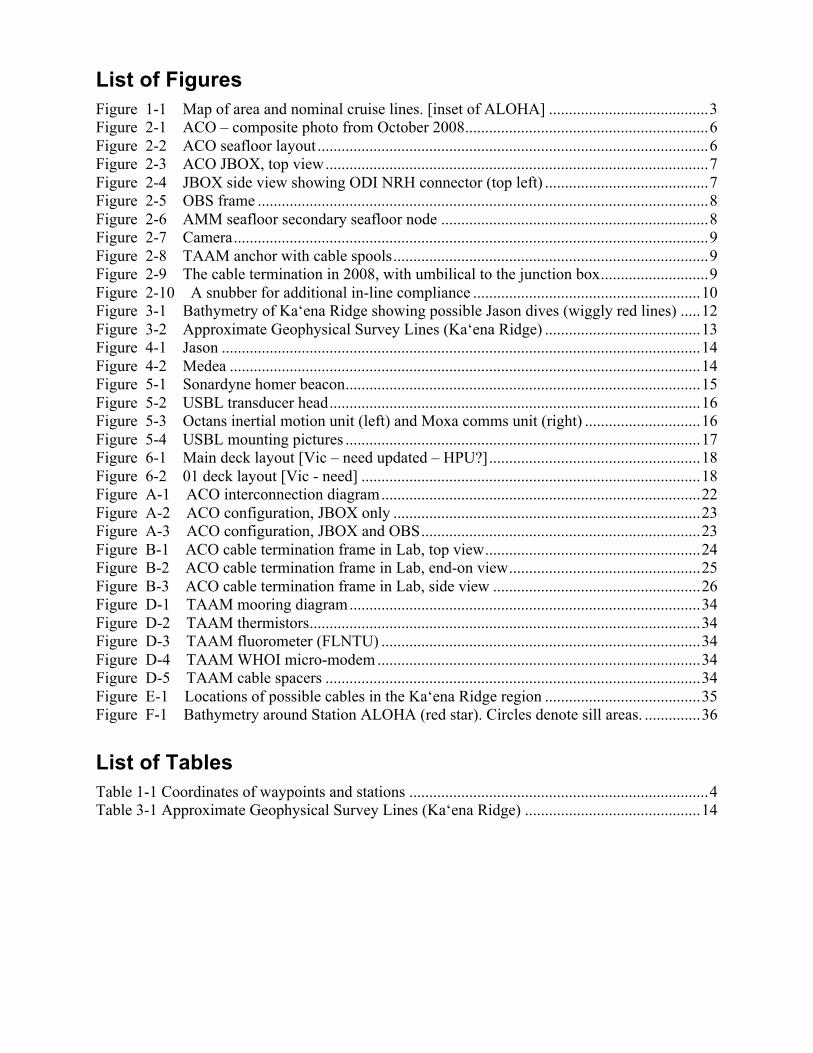
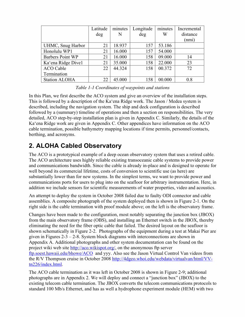
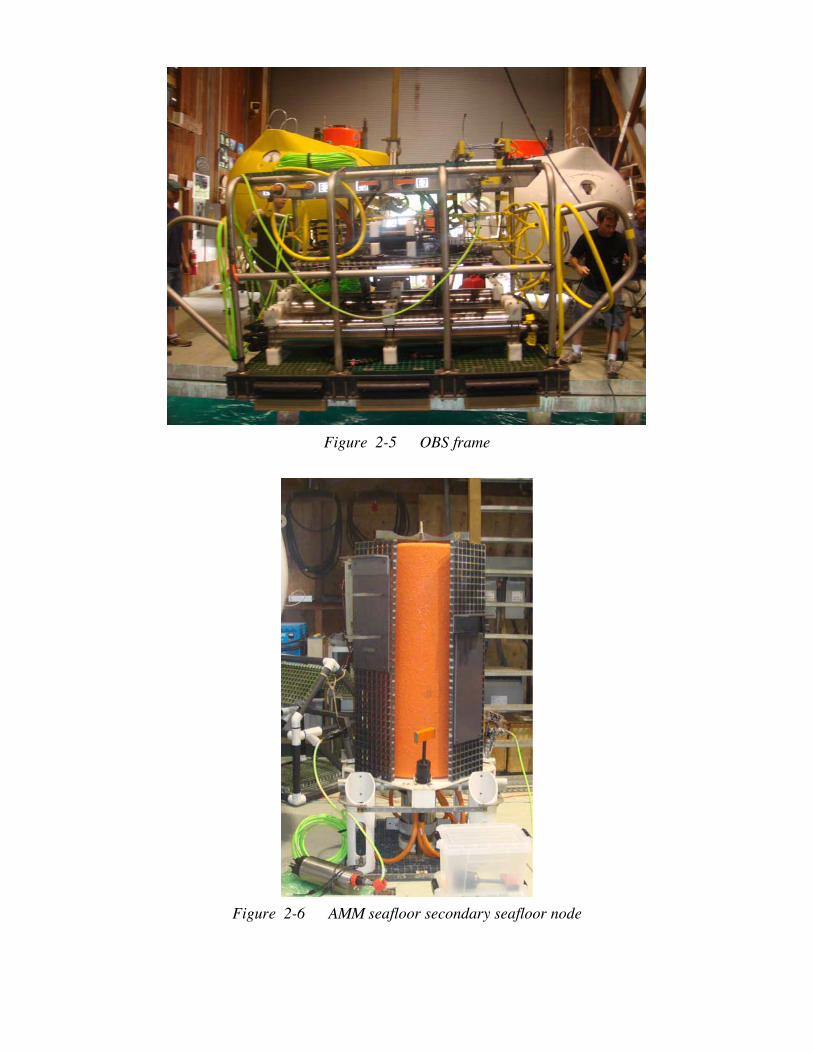
An attempt to deploy the system in October 2008 failed due to faulty ODI connector and cable assemblies. A composite photograph of the system deployed then is shown in Figure 2-1. On the right side is the cable termination with proof module above; on the left is the observatory frame. Changes have been made to the configuration, most notably separating the junction box (JBOX) from the main observatory frame (OBS), and installing an Ethernet switch in the JBOX, thereby eliminating the need for the fiber optic cable that failed. The desired layout on the seafloor is shown schematically in Figure 2-2. Photographs of the equipment during a test at Makai Pier are given in Figures 2-3 – 2-8. System block diagrams with interconnections are shown in Appendix A. Additional photographs and other system documentation can be found on the project wiki web site http://aco.wikispot.org/, on the anonymous ftp server ftp.soest.hawaii.edu/bhowe/ACO and yyy. Also see the Jason Virtual Control Van videos from the R/V Thompson cruise in October 2008 http://4dgeo.whoi.edu/webdata/virtualvan/html/VV-tn226/index.html. The ACO cable termination as it was left in October 2008 is shown in Figure 2-9; additional photographs are in Appendix 2. We will deploy and connect a “junction box” (JBOX) to the existing telecom cable termination. The JBOX converts the telecom communications protocols to standard 100 Mb/s Ethernet, and has as well a hydrophone experiment module (HEM) with two
hydrophones and a pressure sensor. Then the “observatory” (OBS) is connected to the JBOX. The OBS converts the dc current on the cable to 48 V and 400 V, and distributes this, the Ethernet, and timing signals to eight user ports. On the observatory are two acoustic Doppler profilers, a temperature/conductivity instrument, and a light (not on picture yet). Additional modules will be installed and connected. First, two modules will be free-falled to the seafloor: the AMM (Aloha-Mars Mooring) seafloor secondary node and the camera. The AMM node provides four additional user ports and has two CTDs and a fluorometer. The camera with two lights and a hydrophone is connected to the AMM node. Lastly, the 200 m tall thermistor array/acoustic modem (TAAM) mooring system will be deployed anchor first under Medea (? Tbd). This mooring system has 10 thermistors spaced vertically and a fluorometer at the top; these are battery operated but communicate along the jacketed wire rope (JWR) with a Seabird inductive modem unit at the base, which is then connected to the observatory. The WHOI acoustic micro-modem at the top of the mooring has its dedicated electromechanical cable that is married to the JWR.
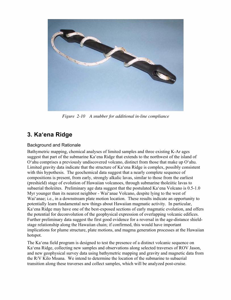
There has been considerable discussion regarding the reducing the risks associated with the deployment of ACO components. The current plan is to deploy the JBOX and OBS beneath Medea with Jason accompanying. There are two known risks. The first is snap loading. If the ship heaves down faster than the package can descend slack in the connecting line will develop, which could snap depending on how the ship continues to move. Three things mitigate this risk. First, the Kilo Moana is a swath ship and therefore pitches relatively little compared to monohulls. Second, we will use ¾-inch nylon with 30 percent elongation at its 13,500 lb breaking strength (rather than Yalex with 14 percent elongation at a breaking strength of 12,500 lb). Third, we will use a “snubber” – to provide additional in-line compliance. Figure 2-10 shows this; its usual use is as a mooring compensator for small to medium boats at marinas.
During the first deployment, before Jason is attached, we will observe the performance of the JBOX beneath Medea with the video when lowered a few 10s of meters. If it appears that additional weight would improve the motion of the JBOX (akin but in an opposite sense to pre-stressing concrete), it will be recovered and weight added.
During descent with three bodies, it is possible for Jason to fail and become fouled with the other bodies (Medea and the ACO package in question). This risk is mitigated by having a small way on (1/4 kt) so that Jason is always streaming aft of Medea and the third body. If Jason’s power should fail, it will drop somewhat, but will continue to remain aft.
We will be prepared to be able to lower the ACO packages in one of three possible ways: 3 bodies (Medea, Jason, and package), 2 bodies (Medea and package), or just one body. The TAAM mooring will likely be deployed using one of the latter twos scenarios. During deployment of the JBOX and OBS, personnel from UH will be at the AT&T Makaha Cable Station to turn power on and off and to control the overall system after connection. If all is working well, command and control can then be done at UH, or anywhere in the world with an IP connection. If all goes according to the plan laid out in detail in Appendix C, the entire operation should take 5 days (???) and x dives (???).
Figure 2-1 ACO – composite photo from October 2008
Figure 2-2 ACO seafloor layout
Figure 2-3 ACO JBOX, top view
Figure 2-4 JBOX side view showing ODI NRH connector (top left)
Figure 2-5 OBS frame
Figure 2-6 AMM seafloor secondary seafloor node
Figure 2-7 Camera
Figure 2-8 TAAM anchor with cable spools
Figure 2-9 The cable termination in 2008, with umbilical to the junction box
Figure 2-10 A snubber for additional in-line compliance
3. Ka‘ena Ridge Background and Rationale Bathymetric mapping, chemical analyses of limited samples and three existing K-Ar ages suggest that part of the submarine Ka‘ena Ridge that extends to the northwest of the island of O‘ahu comprises a previously undiscovered volcano, distinct from those that make up O‘ahu. Limited gravity data indicate that the structure of Ka‘ena Ridge is complex, possibly consistent with this hypothesis. The geochemical data suggest that a nearly complete sequence of compositions is present, from early, strongly alkalic lavas, similar to those from the earliest (preshield) stage of evolution of Hawaiian volcanoes, through submarine tholeiitic lavas to subaerial tholeiites. Preliminary age data suggest that the postulated Ka‘ena Volcano is 0.5-1.0 Myr younger than its nearest neighbor - Wai‘anae Volcano, despite lying to the west of Wai‘anae; i.e., in a downstream plate motion location. These results indicate an opportunity to potentially learn fundamental new things about Hawaiian magmatic activity. In particular, Ka‘ena Ridge may have one of the best-exposed sections of early magmatic evolution, and offers the potential for deconvolution of the geophysical expression of overlapping volcanic edifices. Further preliminary data suggest the first good evidence for a reversal in the age-distance shield-stage relationship along the Hawaiian chain; if confirmed, this would have important implications for plume structure, plate motions, and magma generation processes at the Hawaiian hotspot.
The Ka‘ena field program is designed to test the presence of a distinct volcanic sequence on Ka‘ena Ridge, collecting new samples and observations along selected traverses of ROV Jason, and new geophysical survey data using bathymetric mapping and gravity and magnetic data from the R/V Kilo Moana. We intend to determine the location of the submarine to subaerial transition along these traverses and collect samples, which will be analyzed post-cruise.
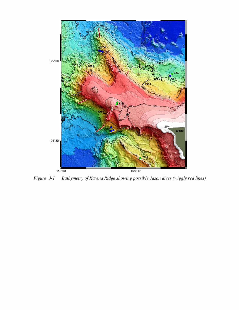
Jason Dives In four days we propose to conduct at least 4 Jason dives to be selected from the possible tracks shown on Figure 3-1. The three highest priority dive targets are one dive along the NW-trending Waialu Ridge < 2000m, and two dives comprising a transect up the SSW side of the lava shield marked by the previous Tiburon dive T325. All dives will be conducted in an up-slope direction. Additional dive tracks will be selected from among the other candidate dive targets depending on results from the first three dives and time remaining.
The first dive will constitute a test of Jason systems and will be done upon initial arrival out of Honolulu. Estimated travel time from Honolulu to first Jason dive area ~5.5 hours. The first dive will be along the ridge just east of dredge track KM-6 (see Figure 3-1). Note 200 meter contours. There are some quite steep scarps but our most important targets are the gentler, probably volcanic constructional slopes. The latter have regional slopes of ~10 degrees so there will almost certainly be local areas with slopes up to at least 30 degrees.
First Jason dive: Launch 158° 41.875’ 21° 37.052’, depth ~1950 m WP 158° 40.914’ 21° 38.872’, depth ~1680m WP 158° 39.464’ 21° 43.035’, depth ~900m Following the first Jason dive we expect to transit to Station Aloha for beginning of ACO operations. We propose running one of the geophysical survey lines (Line D?, see below) from south to north en route to Station Aloha.
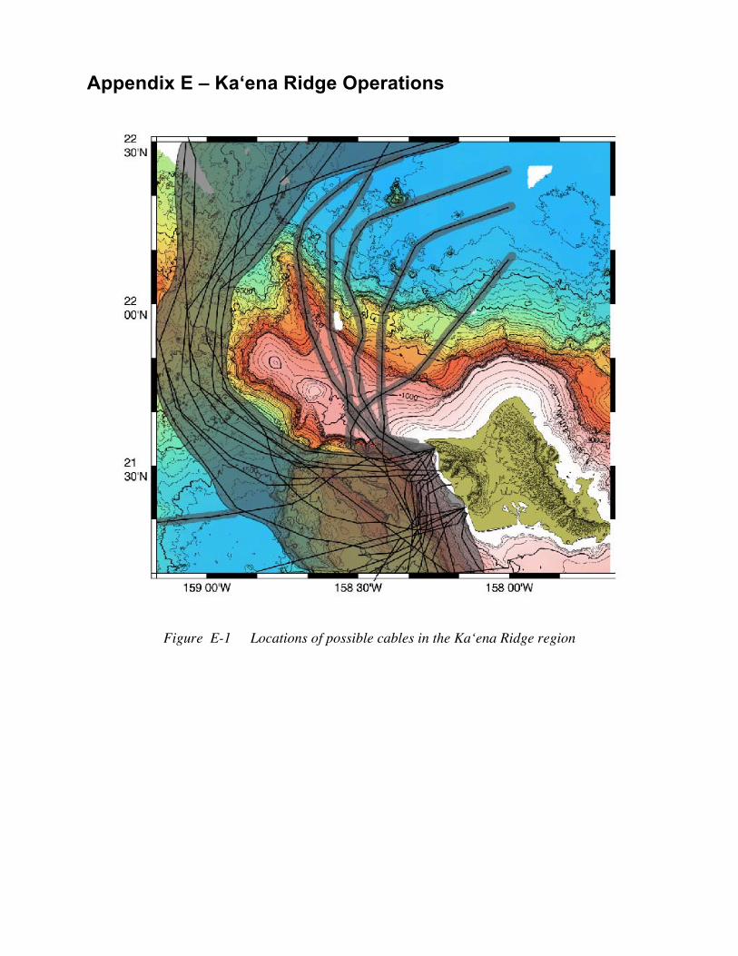
A possible complication to Jason dive operations is the presence of multiple telecommunication cables in the area. In Appendix E, a figure shows some possible cable locations. These locations are not known to be accurate nor necessarily complete.
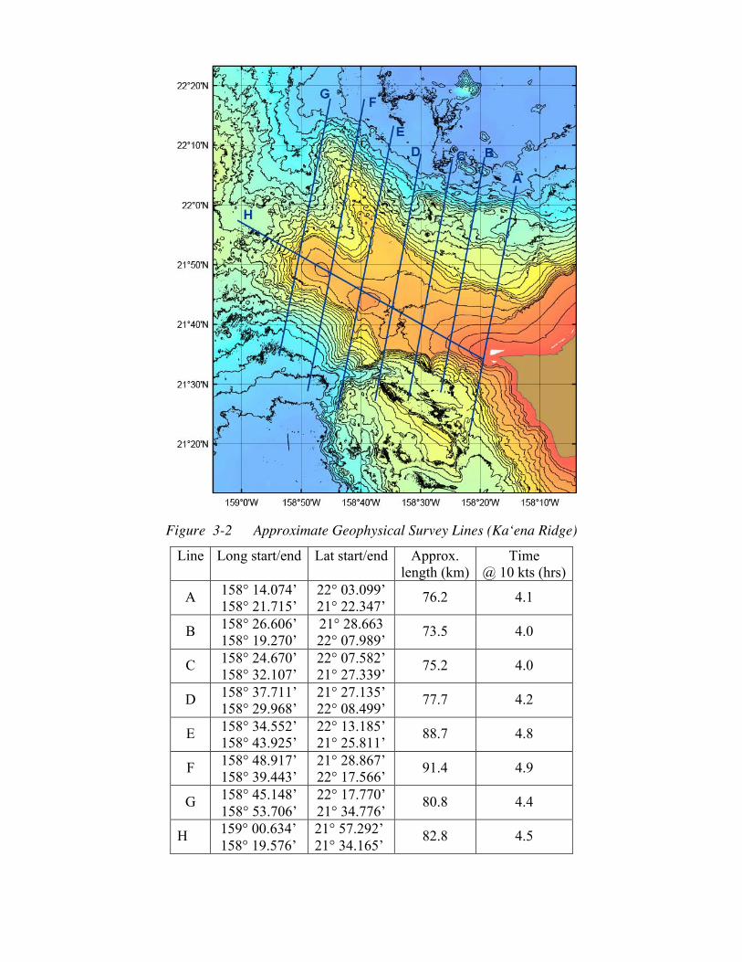
Geophysical Surveys Geophysical surveys will be run for crossings of opportunity across Ka‘ena Ridge and during turn-around times between Jason dives. Possible new geophysical survey lines are shown on figure 3. These survey lines will record gravity (shipboard gravimeter) and magnetics (towed magnetometer) run along straight lines at relatively high speed (to be determined but preferably at least 10 kts). Potential survey lines are described in Table 1, and shown on Fig. 3.3. These lines can be run in either direction, but must run without turns.
Figure 3-1 Bathymetry of Ka‘ena Ridge showing possible Jason dives (wiggly red lines)
4. Jason/Medea Jason is a two-body ROV system (Figures 4-1 and 4-2). A fiber-optic tether delivers electrical power and commands from the ship through Medea and down to Jason, which then returns data and live video imagery. Medea serves as a shock absorber, buffering Jason from the movements of the ship, while providing lighting and a bird’s eye view of the ROV during seafloor operations. On this cruise, the ship’s 0.681-inch electro-optical-mechanical cable is used as the main umbilical to Medea. Navigation is discussed in the next section.
Figure 4-1 Jason
Figure 4-2 Medea
5. Navigation Jason will navigate in three ways. First and simplest when within 200 m of the bottom, Jason uses a Doppler velocity log that gives, when integrated to obtain position, very good relative positioning within 200 m - 300 m of the seafloor. Second, some of the bottom packages will have Sonardyne “homer” beacons (35–55 kHz; Figure 4-3) and Jason can navigate relative to these, using measured roundtrip travel times.
Figure 5-1 Sonardyne homer beacon
Lastly, for large area coverage, a Sonardyne ultra-short-baseline (USBL) system will be installed on the ship. A transducer pole (actually a triangular truss “radio mast”, see next section) mounted in the forward starboard transducer well will be used to lower the USBL sensor head 6-ft below the bottom of the hull. It will measure range and 2-d angle to beacons on Medea, Jason, and our packages. Early in the cruise a fixed beacon on the bottom will be surveyed in to determine offsets, so that absolute position can then be obtained. There is also an inertial motion unit on the transducer pole to directly measure angular motion and accelerations. The ultra-short baseline transducer is a Sonardyne Marksman LUSBL Model 8023 with a 50° wide downward looking beam. The accuracy specification is 0.27 percent 1 Drms Slant Range, i.e., 63 per cent of fixes lie within 13.5 meter radius in 5,000 meters water depth.
The USBL transducer pole will be installed forward in the starboard instrument well. Pictures taken during the fabrication process are shown below (Figure x-y). The pole is inserted through he weather deck above the galley storeroom. A chain fall will be attached to the ceiling of the room above the transducer well to raise and lower it. An inertial motion unit will be mounted directly to the top of the pole. When not being moved, a cap plate will be installed on the top of the well, surrounding the pole (when up) or covering the well when down. Electronics will be set up next to the well (???) so only an Ethernet cable needs to run to the Jason control van.
Figure 5-2 USBL transducer head
Figure 5-3 Octans inertial motion unit (left) and Moxa comms unit (right)
Figure 5-4 USBL mounting pictures
6. Deck Layout The main and O1 deck layouts are shown in Figures 5-1 and 5-2. Jason and its crane reside on the port quarter. Medea will normally resides on the centerline under the A-frame. The TSE winch, used for the ACO package over boarding as well as for the TAAM mooring deployment, sits off-center, lined up with the starboard outboard block on the A-frame. The TAAM mooring anchor sits just aft of the TSE winch. The Jason tool van sits on the starboard quarter as close to the rails as possible (room for chain binders on corners). In the staging bay, the JBOX, OBS and AMM packages reside, connected up to electronics in Lab 2. Interior space is allocated as follows: Lab 2 is divided between Howe (ACO command and control electronics; electronics) and Lukas (sensor preparation and monitoring, mooring). Sinton will use the wet lab and the hydro lab for cataloging and storing rock samples, as well as cutting rock samples (in wet lab, with 208V from the deck socket). The Jason crew will use Lab 1 and the Chem lab for data and electronics, respectively.
On the O1 level, the Jason control vans will be sited on the port side; the rigging van will be opposite on the starboard side (Figure 6-2). The magnetometer winch will be sited just starboard of the aft control station house. Specific locations for the elevator (used to transfer rock samples from the bottom during Ka‘ena Ridge operations – one or two or three??), the camera tripod, and wire baskets for mooring glass balls and hardware are yet to be determined.
Figure 6-1 Main deck layout [Vic – need updated – HPU?]
Figure 6-2 01 deck layout [Vic - need]
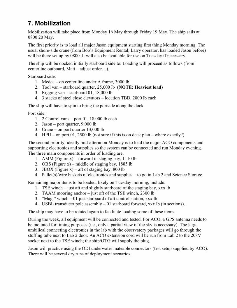
7. Mobilization Mobilization will take place from Monday 16 May through Friday 19 May. The ship sails at 0800 20 May.
The first priority is to load all major Jason equipment starting first thing Monday morning. The usual shore-side crane (from Bob’s Equipment Rental; Larry operator, has loaded Jason before) will be there set up by 0800. It will also be available for use on Tuesday if necessary. The ship will be docked initially starboard side to. Loading will proceed as follows (from centerline outboard, Matt – adjust order…). Starboard side:
1. Medea – on center line under A frame, 3000 lb 2. Tool van – starboard quarter, 25,000 lb (NOTE: Heaviest load) 3. Rigging van – starboard 01, 18,000 lb 4. 3 stacks of steel close elevators – location TBD, 2800 lb each
The ship will have to spin to bring the portside along the dock. Port side:
1. 2 Control vans – port 01, 18,000 lb each 2. Jason – port quarter, 9,000 lb 3. Crane – on port quarter 13,000 lb 4. HPU – on port 01, 2500 lb (not sure if this is on deck plan – where exactly?)
The second priority, ideally mid-afternoon Monday is to load the major ACO components and supporting electronics and supplies so the system can be connected and run Monday evening. The three main components in order of loading are:
1. AMM (Figure x) – forward in staging bay, 1110 lb 2. OBS (Figure x) – middle of staging bay, 1885 lb 3. JBOX (Figure x) – aft of staging bay, 800 lb 4. Pallet(s)/wire baskets of electronics and supplies – to go in Lab 2 and Science Storage
Remaining major items to be loaded, likely on Tuesday morning, include: 1. TSE winch – just aft and slightly starboard of the staging bay, xxx lb 2. TAAM mooring anchor – just oft of the TSE winch, 2300 lb 3. “Magi” winch – 01 just starboard of aft control station, xxx lb 4. USBL transducer pole assembly – 01 starboard forward, xxx lb (in sections).
The ship may have to be rotated again to facilitate loading some of these items. During the week, all equipment will be connected and tested. For ACO, a GPS antenna needs to be mounted for timing purposes (i.e., only a partial view of the sky is necessary). The large umbilical connecting electronics in the lab with the observatory packages will go through the stuffing tube next to Lab 2 door. An ACO extension cord will be run from Lab 2 to the 208V socket next to the TSE winch; the ship/OTG will supply the plug. Jason will practice using the ODI underwater mateable connectors (test setup supplied by ACO). There will be several dry runs of deployment scenarios.
8. Responsibilities The ACO science team is responsible for all the ACO packages, testing and preparing these for deployment, and providing science direction to the Jason crew during operations.
Good communications with the shore party will be essential. ACO will bring two Iridium phones. The ship will provide a third. The ship will provide Internet connectivity.
The Jason team will operate Jason and Medea, and be in charge of the deck [correct?] during all deployment operations that involve their equipment. Others?
Jason will supply all bridles and lines associated with packages under Medea. ACO will bring two working acoustic releases with dualing hardware and/or a strong back. Jason will bring 1 acoustic release as a backup. [models?] ACO, Jason, and OTG will each bring a DS-7000 deck box or equivalent.
Jason will provide two deep homer beacons. These will supplement the two UH ones (one is on a 10-ft mini-mooring next to the cable termination frame, likely dead now, and one is in-hand, along with three new alkaline battery packs, one lithium battery pack, and 3 (?) spare compression seals).
ACO will supply holsters suitable for homer beacons and ODI connectors on all frames. Jason will provide at least three USBL beacons with holsters that can be deployed on ACO (and other) packages. Jason will bring 1 (or 2?) elevators for rock samples. ?
Jason will provide spare steel weights (20 lb pieces) – how much? ACO will have 8 “spelter sockets” – old cable terminations each ~80 lb. Other steel/lead? Chain, shackles?
Jason will bring its sediment suction system for ACO to test/see in action for future use with the aragonite/calcite on the seawater return.
The ship will operate much of the time in dynamic positioning. Given recent past problems with the bow thruster, this needs to be inspected and tested prior to this cruise. The after steering station must be operational. This entire system must be checked out before the cruise and it must be fully operational with all backup and redundant systems operational.
The ship and OTG will provide deep and shallow water multibeam swath bathymetry, sub-bottom echosounders (3.5 kHz and 12 kHz), acoustic Doppler current profiler data/plots (using 38 kHz and 300 KHz instruments), marine gravimeter, and magnetometer and winch, two air tuggers, pallet jack, …
The TSE winch needs to be fully inspected, maintained per manufacturers requirements and tested prior to the cruise. The testing should include at a minimum a pull test when installed on deck to 8000 lb (?) at the drum. More …
9. Cruise Timeline At this point, this table is a strawman schedule. I am awaiting Grant’s detail timeline for the ACO ops that will be in Appendix C.
There are additional tasks being called out to accomplish if we are so fortunate to have extra time: bathymetry surveying around the ALOHA site, and on and around the Ka‘ena Ridge (Appendix F and Figure 3-2, respectively).
Appendix A – ACO Diagrams The following diagrams show components of ACO in a schematic form, naming frames, connectors and cables, pressure cases and endcaps, sensors, etc.
Figure A-1 ACO interconnection diagram
Figure A-2 ACO configuration, JBOX only
Figure A-3 ACO configuration, JBOX and OBS
Appendix B – ACO – Cable Termination Detail One of the more crucial operations is the connection of the hybrid fiber optic/electrical ODI NRH umbilical from the JBOX to the corresponding mating connector on the sea cable termination frame on the seafloor.
Following are pictures of this SL280 cable termination with dimensional details. (from Dave Harris, 5 June 2010.)
Figure B-1 ACO cable termination frame in Lab, top view
Figure B-2 ACO cable termination frame in Lab, end-on view
Figure B-3 ACO cable termination frame in Lab, side view
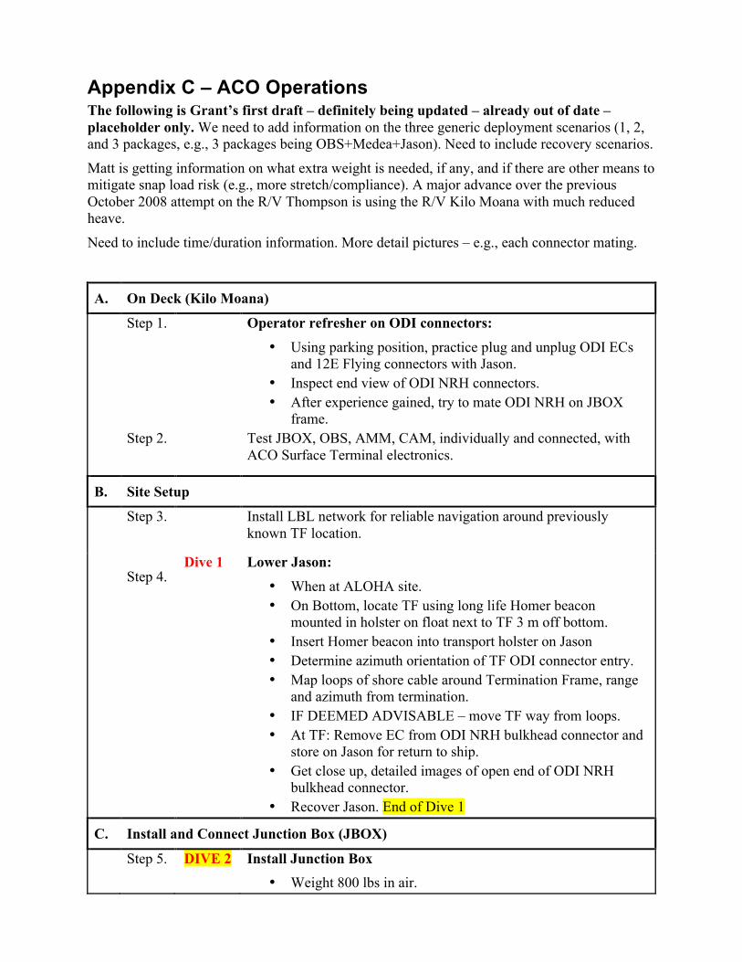
Appendix C – ACO Operations The following is Grant’s first draft – definitely being updated – already out of date – placeholder only. We need to add information on the three generic deployment scenarios (1, 2, and 3 packages, e.g., 3 packages being OBS+Medea+Jason). Need to include recovery scenarios.
Matt is getting information on what extra weight is needed, if any, and if there are other means to mitigate snap load risk (e.g., more stretch/compliance). A major advance over the previous October 2008 attempt on the R/V Thompson is using the R/V Kilo Moana with much reduced heave.
Need to include time/duration information. More detail pictures – e.g., each connector mating.
A. On Deck (Kilo Moana)
Step 1. Operator refresher on ODI connectors: • Using parking position, practice plug and unplug ODI ECs
and 12E Flying connectors with Jason. • Inspect end view of ODI NRH connectors. • After experience gained, try to mate ODI NRH on JBOX
frame. Step 2. Test JBOX, OBS, AMM, CAM, individually and connected, with
ACO Surface Terminal electronics.
B. Site Setup
Step 3. Install LBL network for reliable navigation around previously known TF location.
Step 4. Dive 1 Lower Jason:
• When at ALOHA site. • On Bottom, locate TF using long life Homer beacon
mounted in holster on float next to TF 3 m off bottom. • Insert Homer beacon into transport holster on Jason • Determine azimuth orientation of TF ODI connector entry. • Map loops of shore cable around Termination Frame, range
and azimuth from termination. • IF DEEMED ADVISABLE – move TF way from loops. • At TF: Remove EC from ODI NRH bulkhead connector and
store on Jason for return to ship. • Get close up, detailed images of open end of ODI NRH
bulkhead connector. • Recover Jason. End of Dive 1
C. Install and Connect Junction Box (JBOX)
Step 5. DIVE 2 Install Junction Box • Weight 800 lbs in air.
• Weight 350 lbs in water. • Add 500 lbs of releaseable chain for lowering. • Install Homer beacon in JBOX holster for recovery in case
of fall. • Lower under Medea. • Position JBOX 4-7 meters from the TF (relative direction?). • Using Medea thrusters, orient bow of JBOX toward TF
connector. This can be done later by JASON. • Release JBOX lifting sling from Medea. • Document JBOX position and orientation. • Recover Medea. – end of Dive 2
Step 6. Dive 3 Connect Junction Box • Lower Jason to JBOX. • At JBOX: Remove Homer beacon from holster and put in
Jason basket. • Remove ODI NRH flying connector on cable JT2 from
parking position on JBOX. • Carry connector and cable to TF. • Verify from Makaha that HV power is OFF. • Insert ODI NRH flying connector into TF bulkhead
connector. (THIS IS THE MOST CRITICAL OPERATION OF THE DEPLOYMENT). Note that excessive force (excessive would be if TF moved) cannot be used. Connector must be lined up correctly to be inserted fully.
• Advise Makaha that connection has been made. • Wait for Makaha to report connection successful. Repeat
mating cycle if necessary. • When good connection reported, recover Jason. End Dive 3
D. Install and Connect Observatory (OBS)
Step 7. Dive 4 Install Observatory Frame • Weight 1885 lbs in air. • Weight 890 lbs in water. • Add 800 lbs of releasable (?) chain to increase weight • Install Homer beacon in OBS holster for recovery case of
fall. • Lower under Medea. • Position bow of OBS between 3 and 5 meters from the stern
of JBOX in line with TF. • Orient bow of OBS toward Stern of JBOX. • Release OBS lifting strap from Medea. • Document position and orientation. • Recover Medea. End of Dive 4
Step 8. Dive 5 Connect Observatory
• Lower Jason. • Locate OBS and JBOX. • At OBS: Remove Homer beacon from holster and put in
Jason basket. • Verify from Makaha that HV power is OFF. • At JBOX: Remove EC from bulkhead labeled PG2 and store
on Jason for return to ship. • At JBOX: Remove ODI connector on cable PG2 from
bulkhead labeled JP1and insert in adjacent parking position (labeled PG2 Park).
• At OBS: Remove EC from ODI connector E5 and store on Jason for later reuse.
• At JBOX: Remove ODI flying connector on cable HE1 from JB1 bulkhead on JB.
• Carry connector and cable to OBS and connect to E5. • At OBS: Remove ODI flying connector JB2 from parking
position on OBS (labeled JB2 Park). • Carry connector and cable to JBOX and connect to JB1
bulkhead (where HE1 was). • At OBS: Install EC from Jason on parking position labeled
JB2 Park. • At OBS: Remove ODI flying connector JP2 from parking
position on OBS (labeled JP2 Park). • Carry JP2 connector and cable to JBOX and connect to JP1
bulkhead (where PG2 was). • Advise Makaha connection has been made. • Wait for Makaha to report successful connection. Adjust
cables and connectors if necessary. • At OBS: When good connection reported, remove ADP
covers and store on Jason for return to ship. • At OBS: Swing CTD arm up and over to port side of OBS. • At OBS: Swing Camera light arm up and over to port side of
OBS. • Recover Jason. End of Dive 5
E. Install ALOHA-MARS Mooring Secondary Node
Step 9. Install AMM • Weight 1110 lbs in air. • Weight 155 lbs in water. • Add 500 lbs of chain for weight. • Install Homer beacon in AMM holster for location after
free fall. • Lower AMM over the side and release when ship is at TF
position.
Step 10. Install CAM • Weight 290 lbs in air. • Weight 110 lbs in water. • Add 500 lbs of chain for weight. [too much for frame?] • Install Homer beacon in CAM holster for location after
free fall. • Lower CAM over the side and release when ship is at TF
position. Step 11. Dive 6 Connect AMM
• Lower Jason. • Locate AMM with Homer beacon. • Disconnect chain from AMM. • Move AMM to 5 meters from stern of OBS along same
line as TF to JBOX to OBS. • Orient Bulkhead J1 toward Stern of OBS. • At AMM: Remove Homer beacon from holster and put on
Jason for return to surface. • Verify from Makaha that Observatory Port 8 power is
OFF. • At OBS: Remove ODI flying connector on cable J1 from
parking position on OBS (Labeled J1 Park). • Carry connector and cable to AMM. • Insert ODI flying connector on cable J1 into AMM ODI
Bulkhead connector J1. • Advise Makaha/Manoa that connection has been made. • Wait for Makaha/Manoa to report successful connection.
Repeat mating cycle if necessary. • When good connection reported, begin Camera Connection
(next)
F. Connect Camera Tripod (CAM)
Step 12. Dive 6 (contd)
Connect CAM • Locate CAM using Homer beacon. • Remove chain weight. • Lift and move CAM to a position 3 m from port beam of
OBS. • Rotate until side between Leg 1 and Leg 2 faces OBS. • At CAM: Remove Homer beacon from holster and put in
Jason basket. • Verify from Makaha/Manoa that the power from
Observatory Port E8 is OFF • At AMM: Remove EC from J5 and store on Jason for
return to ship. • At CAM: Remove ODI flying connector on CAM cable
from parking position on CAM. • Carry connector and cable to AMM. • Insert ODI flying connector on CAM cable into AMM
ODI Bulkhead connector J5. • Advise Makaha/Manoa that CAM is connected. • Wait for Makaha/Manoa to report successful connection.
Repeat mating cycle if necessary. • When good connection reported, coordinate Jason actions
with Makaha/Manoa while camera records action for PR purposes.
• When done with video recording, recover Jason. End of Dive 6
H. Install Thermistor Array/Acoustic Modem (TAAM) Mooring
Step 13. Install TAAM • Weight ??? lbs in air. • Weight ??? lbs in water. • Install Homer beacon in TAMM holster for location in
case of fall. • Pay out TAAM array anchor first and connect top of
mooring to trawl wire with acoustic release. • Attach LBL beacon to trawl wire above release for
tracking while lowering. • Lower with trawl winch about 200 meters on starboard
beam of OBS position. • Track during Lowering with LBL. • When anchor 10 m above bottom, move to 50 m from OBS • When in position, activate release. • Recover trawl wire with release and LBL beacon.
Step 14. Dive 7 Connect TAAM • Lower Jason. • At OBS: Remove EC from ODI Bulkhead E1 and store on
Jason for return to ship. • Locate TAAM. • At TAAM: Remove Homer beacon from holster and put in
Jason basket. • Verify from Makaha/Manoa that power for Observatory
Port 1 is OFF. • At TAAM: Remove ODI flying connector on cable T1
from stored position inside cable reel. • Move up and directly away from reel to pay out full cable
length, flying backwards with Jason observing the cable • When cable tension how measured? Catenary? Distance?
indicates all cable is off reel, fly constant arc to OBS. • At OBS: Insert ODI flying connector on T1 cable into OBS
ODI Bulkhead connector E1. • At OBS: Remove EC from ODI Bulkhead E3 and store on
Jason for return to surface. • At TAAM: Remove ODI flying connector on cable T3
from stored position inside cable reel. • Move up and directly away from reel (opposite direction
from T1 cable) to pay out full cable length. • When cable tension indicates all cable is off reel, fly
constant arc to OBS. • Carry connector and cable to OBS. • Verify from Makaha/Manoa that power to Observatory
port 3 is OFF. • At OBS: Insert ODI flying connector on T3 cable into OBS
ODI Bulkhead connector E3. • Wait for Makaha/Manoa to report successful connection.
Repeat mating cycle if necessary. • When good connection reported, recover Jason. • End of Dive 7
H. PAU HANA (on the ship, at least)
Appendix D – TAAM Mooring This drawing will be updated to include the fluorometer and the acoustic modem.
Figure D-1 TAAM mooring diagram
Figure D-2 TAAM thermistors
Figure D-3 TAAM fluorometer (FLNTU)
Figure D-4 TAAM WHOI micro-modem
Figure D-5 TAAM cable spacers
Appendix E – Ka‘ena Ridge Operations
Figure E-1 Locations of possible cables in the Ka‘ena Ridge region
Appendix F – Bathymetry in the ALOHA area If there is time available during the cruise, additional deep multibeam bathymetry data may be collected. There are several areas where this would be useful. Collecting this data will naturally depend on evaluating other competing tasks and priorities, on time available, ship location, etc. See Figure F-1 for reference.
The first priority would be to refine the map of the northeast Kauai ridge to determine the controlling sill depth on that side of the Kauai Deep. The controlling sill depth is the shallowest point along the deepest channel connecting the neighboring basins. In other words, we would like to find the location, extent and depth of the saddle point.
The two sill areas of interest are north of Kauai and around the Oahu Seamounts (red circles in Figure F-1). In the latter area, we would like to know the passages through which cold Maui Deep water finds it way into the Kauai Deep. In some places, there are no multi-beam data. In some others, the data are sparse and you can see on more detailed charts with the raw data the ship tracks with offsets. The high-resolution bathymetry that is available in some places arises from multiples sources and sophisticated merging analysis, with uncertain uncertainties.
Of secondary importance would be to fill in the few obvious, larger areas with no swath data.
Figure F-1 Bathymetry around Station ALOHA (red star). Circles denote sill areas.
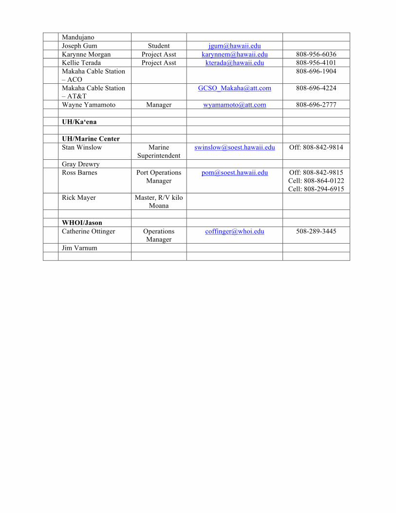
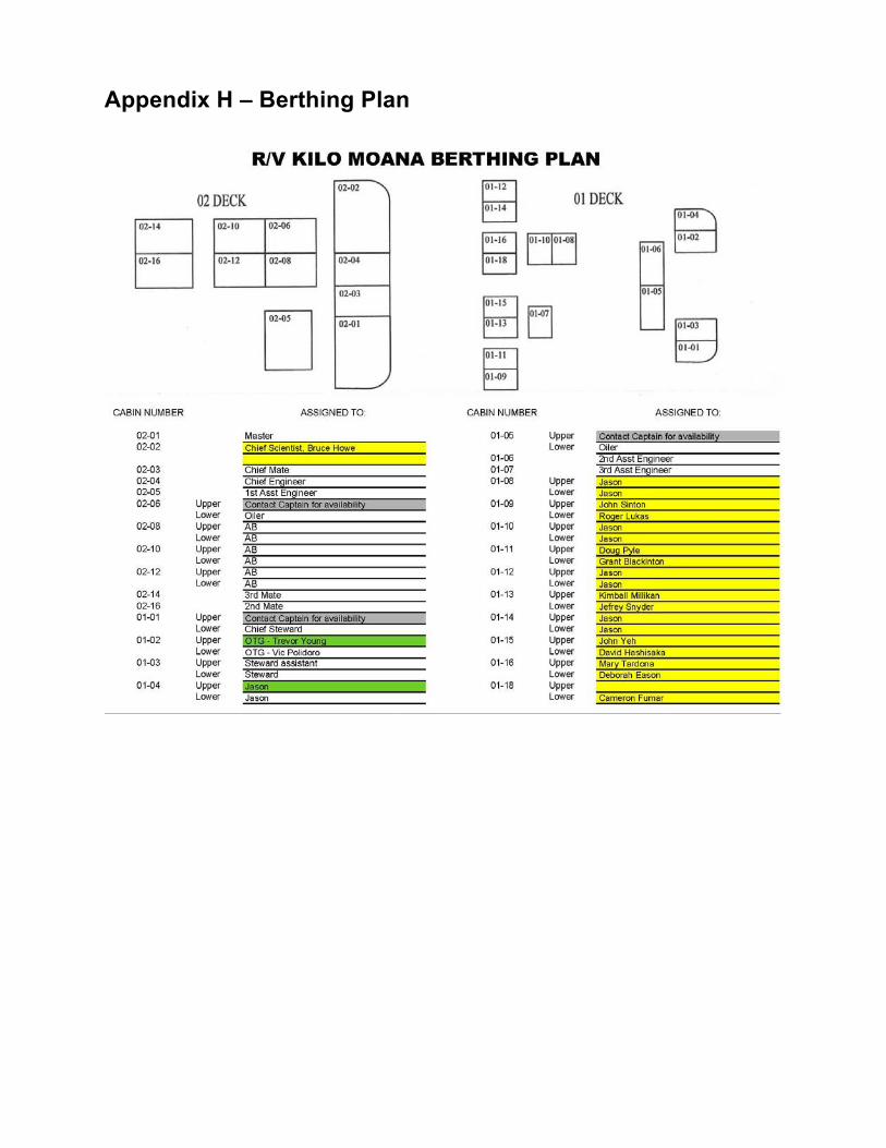
Appendix G – Cruise Participants and Contacts List
Name Position Email Phone Cruise Participants UH/ACO
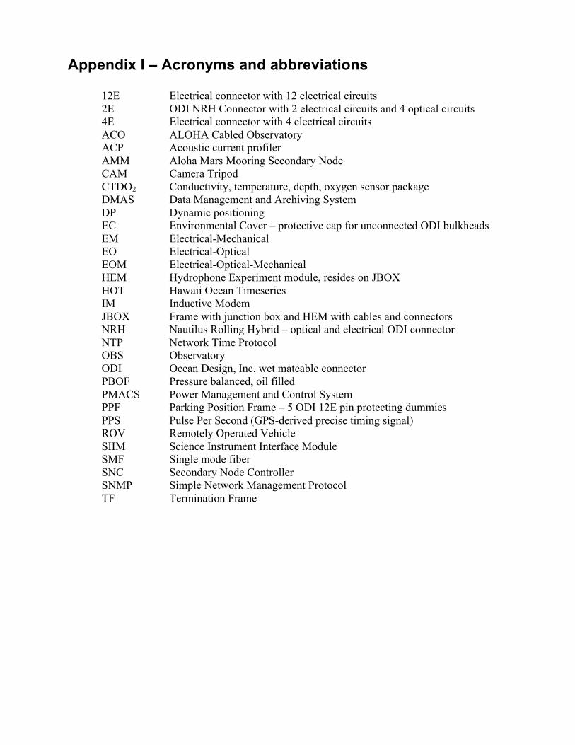
Appendix I – Acronyms and abbreviations 12E Electrical connector with 12 electrical circuits 2E ODI NRH Connector with 2 electrical circuits and 4 optical circuits 4E Electrical connector with 4 electrical circuits ACO ALOHA Cabled Observatory ACP Acoustic current profiler AMM Aloha Mars Mooring Secondary Node CAM Camera Tripod CTDO2 Conductivity, temperature, depth, oxygen sensor package DMAS Data Management and Archiving System DP Dynamic positioning EC Environmental Cover – protective cap for unconnected ODI bulkheads EM Electrical-Mechanical EO Electrical-Optical EOM Electrical-Optical-Mechanical HEM Hydrophone Experiment module, resides on JBOX HOT Hawaii Ocean Timeseries IM Inductive Modem JBOX Frame with junction box and HEM with cables and connectors NRH Nautilus Rolling Hybrid – optical and electrical ODI connector NTP Network Time Protocol OBS Observatory ODI Ocean Design, Inc. wet mateable connector PBOF Pressure balanced, oil filled PMACS Power Management and Control System PPF Parking Position Frame – 5 ODI 12E pin protecting dummies PPS Pulse Per Second (GPS-derived precise timing signal) ROV Remotely Operated Vehicle SIIM Science Instrument Interface Module SMF Single mode fiber SNC Secondary Node Controller SNMP Simple Network Management Protocol TF Termination Frame