107
Cryogenic Safety with Emphasis on Overpressure Protection of Low Temperature Helium Vessels Tom Peterson, SLAC USPAS January, 2017

Cryogenic Safety with Emphasis on Overpressure Protection of
Low Temperature Helium Vessels
Tom Peterson, SLAC
USPAS
January, 2017
Two MRI system event videos
• http://www.youtube.com/watch?v=1R7Ksfo
sV-o
• http://www.youtube.com/watch?v=sceO38i
djic&feature=related
USPAS,
January, 2017 Cryogenic Safety, Tom Peterson and John Weisend 2
USPAS,
January, 2017 Cryogenic Safety, Tom Peterson and John Weisend
3
• Introduction
• The basic hazards – selections from a general cryogenic safety training class
• Lessons learned from accidents
• Cryogenic pressure safety
• ODH analysis
Outline

Introduction
• The purpose of this lecture is to provide a review of
cryogenic safety and pressurized gas hazards
• Most commonly used cryogenic fluids in accelerator work
are argon (Ar), nitrogen (N2), helium (He) and hydrogen
(H2). These fluids are used in liquid and gaseous form.
• These low temperature fluids have the potential for
creating dangerous working environments.
• Everyone who works with cryogenic fluids must know
their hazards and how to work safely with them.
USPAS,
January, 2017 Cryogenic Safety, Tom Peterson and John Weisend
4
4

USPAS,
January, 2017 Cryogenic Safety, Tom Peterson and John Weisend
5
The basic hazards due to helium
and nitrogen • Freezing, extreme cold
– Burns skin, eyes
– Embrittlement of material
• Pressure, force of blast, propelled objects
– Dust, debris
– Pipe cap, valve stem and bonnet
– Expansion in a closed volume
• Noise
– Compressors
– Gas vents
• ODH--Oxygen Deficiency Hazard
– Nitrogen
– Helium
• Fire -- hydrogen burns easily and with a clear flame
• Oxygen enriched air -- enhanced burning of flammable materials

USPAS,
January, 2017 Cryogenic Safety, Tom Peterson and John Weisend
6
Oxygen Deficiency Hazard (ODH)
• Oxygen Deficiency Hazard (ODH) is caused due to oxygen displacement.
• ODH is a serious hazard usually occur without any warning
• ODH is addressed by Fermilab’s FESHM 5064, which is available via the Fermilab
web site.
• The cold, heavy gas from evaporating cryogenic liquid does not disperse very well
and can group together in surrounding areas and will displace air.
• Some gases (He, H2) while cold may be lighter than air. They may partially mix
with surrounding air, or stratify as they warm up.
• A hazard with helium and other inert gases is to have a pockets of trapped gas up
high in a building, which may cause ODH. (A concern is that a person could pass out
and fall off a ladder when replacing a lamp, for example.)
• Be aware of the hazards associated with large volumes of cryogens in a small space
(for example, rolling a 160 liter LN2 dewar into a small room)
6

Extreme cold hazard
• Cryogenic liquids and cold vapors can cause a
thermal burn injuries
• Brief exposures may damage delicate tissues
(eyes, skin, etc).
• The skin, when not protected, can stick to metal
that is cooled by cryogenic liquids and when
pulled away the skin can tear
• Even non-metallic materials are very dangerous to
touch at cryogenic temperatures
USPAS,
January, 2017 Cryogenic Safety, Tom Peterson and John Weisend
7
7

Fire Hazard • Flammable cryogenic gases like H2 can burn or explode
• Hydrogen is colorless, odorless, non-toxic, highly
flammable and explosive in the presence of air or oxygen
in the right concentration. It forms a flammable mixture
when it exists at 4 to 74%. Hydrogen, since it is lighter
than air, will tend to form pockets of gas along ceilings,
which can lead to an explosion or fire hazard.
• A flashing or rotating blue light is used at Fermilab to
indicate that hydrogen is present in experimental apparatus
in the area. Typically other institutions will also provide
similar warning signals.
• Further training is required for qualification for working
with hydrogen USPAS,
January, 2017 Cryogenic Safety, Tom Peterson and John Weisend
8
8

Oxygen Enriched Air
• Cryogenic fluids like LHe, LN2 and LH2 can
easily liquefy the air they come in contact with.
• Liquid air can condense on a surface cooled LHe,
LN2 and LH2 .
• N2 has smaller latent heat than Oxygen (O2), thus
evaporates more rapidly than oxygen from the
liquid air. This action leaves behind a liquid air
mixture which, when evaporated, gives a high
concentration of oxygen.
• This O2 enriched air presents highly flammable
atmosphere.
USPAS,
January, 2017 Cryogenic Safety, Tom Peterson and John Weisend
9
9
Over Pressurization or Explosion
due to rapid expansion • Without adequate venting or pressure-relief
devices on the containers, enormous pressures can
build up which can cause an explosion.
• Unusual or accidental conditions such as an
external fire, or a break in the vacuum which
provides thermal insulation, may cause a very
rapid pressure rise.
• The pressure relief valve must be properly
installed and free from obstruction.
USPAS,
January, 2017 Cryogenic Safety, Tom Peterson and John Weisend
10 1/5/2017 10

Protection from cryogenic hazards
• Always wear personal protective equipment while handling cryogenic liquids.
This includes: gloves, face shields, hearing protection, loose fitting thermal
insulated or leather long sleeve shirts, trousers, safety shoes
• Only trained and qualified personal should be allowed to handle, transport or
storing liquefied gases.
• Proper storage is essential for cryogenic fluids
• Depressurize system
• Stand aside from vent
• Be aware of closed volumes into which liquid cryogens might leak
• Do not leave open mouth dewars open
• Purge and evacuate all equipment before operation
• Use cryogens in a properly ventilated areas only
USPAS,
January, 2017 Cryogenic Safety, Tom Peterson and John Weisend
11
11

Lessons Learned
• The following are a set of “lessons learned” which
have been compiled from various sources. One
primary source of lessons learned is the American
Industrial Hygiene Association, which has a
section of their website describing several
cryogenic accidents:
http://www2.umdnj.edu/eohssweb/aiha/accidents/c
ryogens.htm has been used as a source of some
different examples of cryogenic hazards.
USPAS,
January, 2017 Cryogenic Safety, Tom Peterson and John Weisend
12

Lessons Learned • Empty 55 gallon drum (1999)
– At the Nevada Test Site, a waste handler was opening new, empty
55 gallon open-top drums. Upon removing the bolt from the drum
lid clamp, the ring blew off and the lid was ejected approximately
5 to 10 feet in the air, just missing the Waste Handler's face. The
drum did not hiss or show signs of pressurization.
– Because the Waste Handler had been properly trained to stand
away from the drum while opening it, he was not injured.
– The event was caused by the drums being manufactured and sealed
at sea level in Los Angeles and subsequently shipped to a much
higher elevation of approximately 6,000 feet at the Nevada Test
Site. The increased elevation, combined with the midday heat,
created sufficient pressure buildup to cause the lid to blow off
when the ring was being released.
– Lesson -- large force with small pressure times large area USPAS,
January, 2017 Cryogenic Safety, Tom Peterson and John Weisend
13

USPAS,
January, 2017 Cryogenic Safety, Tom Peterson and John Weisend
14
Lessons learned (continued) • 50 liter LN2 laboratory dewar explosion
– Transfer of LN2 from 160 liter dewar to 50 liter “laboratory” dewar
– Flex hose end from 160 l dewar would not fit in lab dewar neck
(normally a “wand” is inserted for filling), so a connection was made
with rubber hose over the OUTSIDE of the lab dewar neck and transfer
hose end
– “Slot” cut in rubber hose for vent
– Failure not initially caused by overpressure, but by cooling of upper part
of neck during fill! Seal between neck and vacuum jacket broke due to
differential thermal contraction.
– Seal to vacuum jacket broke after lab dewar nearly full, subsequent
overpressure with lack of sufficient vent caused explosion of lab dewar
– One person badly injured
– Lesson -- rupture of insulating vacuum with restricted venting resulted in
explosion

USPAS,
January, 2017 Cryogenic Safety, Tom Peterson and John Weisend
15
Lessons learned (continued) • Two workers at a Union Carbide plant were inspecting a flange surface
on a 48” diameter pipe with an ultraviolet light.
• They draped black plastic over the end of the pipe to create shade for seeing any glow from material in the ultraviolet.
• The workers did not know there were some sources of nitrogen connected to the pipe. In fact, one of the workers had helped to start a purge on another section of pipe. But the system was so complex, he did not know they were connected.
• When they went under the cover to do the inspection, both workers quickly passed out from lack of oxygen. One died; the other was seriously injured.
• OSHA ultimately cited the company for violation of the confined space entry standard.
• Lesson -- be aware of potentially confined spaces, possible unlabeled ODH hazards

Topics in cryogenic pressure safety • ASME pressure vessel code, ASME pressure piping code
– We will not discuss vessel or piping code details, just provide some references to relevant sections
• Sources of pressure
• Thermodynamics of cryogen expansion and venting
• Analytical methods for vent line and relief sizing
• Relief devices
• Example of a venting system analysis
• Examples of the impact on cryostat design
• Oxygen Deficiency Hazard (ODH) analysis
• Conclusions and references
USPAS,
January, 2017 Cryogenic Safety, Tom Peterson and John Weisend 16

Pressure vessel and piping codes
• ASME Boiler and Pressure Vessel Code and ASME B31 Piping Codes
– I will not go into detail about the design of pressure vessels or piping per ASME code
• Will focus on emergency venting and system issues
– In general, we try to purchase vessels built to the code from code-authorized shops
– Where code-stamping is not possible, we design (or specify designs) to the intent of the code and note implications of exceptions to the code
• Fermilab’s ES&H Manual (FESHM) pressure vessel standard, FESHM 5031, is available online at http://esh-docdb.fnal.gov/cgi-bin/ShowDocument?docid=456
USPAS,
January, 2017 Cryogenic Safety, Tom Peterson and John Weisend 17

ASME pressure vessel code --
Section VIII, Division 1 • “Div. 1 is directed at the economical design of basic
pressure vessels, intending to provide functionality and safety with a minimum of analysis and inspection. Rules are presented which, if applicable, must be used. Common component geometries can be designed for pressure entirely by these rules. Adherence to specified details of attachment eliminates the need for detailed analysis of these features for pressure loading. NDE of welds can typically be avoided by taking a penalty in overall thickness of a component.”
• Quoted from “Guidelines for the Design, Fabrication, Testing and Installation of SRF Nb Cavities,” Fermilab Technical Division Technical Note TD-09-005
USPAS,
January, 2017 Cryogenic Safety, Tom Peterson and John Weisend 18

ASME pressure vessel code --
Section VIII, Division 2 • “Div. 2 is directed at engineered pressure vessels, which
can be thought of as vessels whose performance
specifications justify the more extensive analysis and
stricter material and fabrication controls and NDE required
by this Division. Thus, while a Div. 2 vessel is likely to be
more efficient than a Div. 1 vessel in terms of total
material used, this efficiency is accompanied by increased
design and fabrication cost.”
• Quoted from “Guidelines for the Design, Fabrication,
Testing and Installation of SRF Nb Cavities,” Fermilab
Technical Division Technical Note TD-09-005
USPAS,
January, 2017 Cryogenic Safety, Tom Peterson and John Weisend 19
Pressure protection • Vessel and piping have a Maximum Allowable Working
Pressure (MAWP) defined by the design of the vessel or system
– A venting system and relief devices must be in place to prevent any event from pressurizing the vessel or piping above the MAWP (plus whatever code allowance may be available)
• Evaluate all pressure sources and possible mass flow rates
• Size the vent line to the relief device
– Temperature and pressure of flow stream
– Typically a pressure drop analysis for turbulent subsonic flow
• Size the relief device
• Size downstream ducting, if any – Downstream piping may be necessary to carry inert gas safely
away from an occupied area or sensitive equipment USPAS,
January, 2017 Cryogenic Safety, Tom Peterson and John Weisend 20

ASME pressure vessel code --
relief devices
• Section VIII of the ASME Code provides
fundamental guidance regarding pressure relief
requirements.
– ASME Section VIII, Division 1, UG-125 through
UG133, for general selection, installation and valve
certification requirements
– ASME Section VIII, Appendix 11 for flow capacity
conversions to SCFM-air
• For Div. 2, relevant information is found in Part 9.
USPAS,
January, 2017 Cryogenic Safety, Tom Peterson and John Weisend 21

Compressed Gas Association publication,
CGA S-1.3, “Pressure Relief Device Standards”
• Extensive guidance on requirements for
relief devices consistent with ASME code
– Applicable where MAWP and venting pressure
exceed 15 psig
• I will not provide a detailed discussion of
CGA S-1.3, but rather just point to a few
key issues and most useful elements of the
standard
USPAS,
January, 2017 Cryogenic Safety, Tom Peterson and John Weisend 22

Note: we take exception to
paragraph 2.2 in CGA S-1.3 • “CGA believes that reclosing PRDs on a container shall be
able to handle all the operational emergency conditions except fire, for which reclosing or nonreclosing PRDs shall be provided. The operational emergency conditions referred to shall include but not be limited to loss of vacuum, runaway fill, and uncontrolled operation of pressure buildup devices.”
• Exception: we treat loss of insulating vacuum to air, with the very high heat flux resulting from condensation on the liquid helium temperature surface of a container, like the fire condition and may use nonreclosing relief devices for
that situation
USPAS,
January, 2017 Cryogenic Safety, Tom Peterson and John Weisend 23
Compressed Gas Association publication,
CGA S-1.3, “Pressure Relief Device Standards”
• From CGA S-1.3: Among the particular issues which must be addressed for low temperature vacuum jacketed helium containers are
– the temperature at which liquid-to-gas evolution should be estimated for the supercritical fluid at its venting pressure (CGA S-1.3 is very useful here; I’ll discuss this)
– the warming of the cold fluid passing through a long vent line (CGA S-1.3 also provides useful practical approximation methods here which I will discuss)
– the volume generated per unit heat added (we have data from lab tests about this which provide useful numbers)
USPAS,
January, 2017 Cryogenic Safety, Tom Peterson and John Weisend 24

Evaluating the venting flow rate
and conditions • Berkeley MRI magnet quench
• https://www.youtube.com/watch?v=QRahB
usouRs
USPAS,
January, 2017 Cryogenic Safety, Tom Peterson and John Weisend 25
Sources of pressure -- mechanical
• Compressors, pumps
– Screw compressors are positive displacement devices
– Worst case flow may be with high suction pressure as limited by
inlet-side reliefs or pump/compressor motor power
• Calculate worst-case flow as highest inlet density combined with
known displacement volume
• Or consider power limitations of pump or compressor motor
• Connection to a higher pressure source, such as a tube
trailer
– Evaluate the mass flow as determined by the pressure drop from
the highest possible source pressure to the MAWP of vessel to be
protected
USPAS,
January, 2017 Cryogenic Safety, Tom Peterson and John Weisend 26

Sources of pressure -- heat • Trapped volume, slow warm-up and pressurization with normal heat
inleak
– All possible volumes which may contain “trapped” (closed off by valves or by other means) cold fluid require small reliefs
– Rate of warm-up may be evaluated, generally slow enough that trapped volume reliefs are not individually analyzed.
• Loss of vacuum to helium with convection and conduction through helium gas
• Sudden large heat influx to a liquid-helium temperature container due to condensation of nitrogen or air on the surface
– Either through MLI or, worst-case, on a bare metal surface
• Stored energy of a magnetic field
– May provide a larger flow rate than loss of insulating vacuum
• Fire, with heat transport through the gas-filled insulation space
USPAS,
January, 2017 Cryogenic Safety, Tom Peterson and John Weisend 27
Nominal heat loads
• Working numbers for making heat load
estimates
– ~1.5 W/m2 from 300 K to MLI-insulated
(typically about 30 layers) cold surface
– ~50 mW/m2 from 80 K to MLI-insulated
(typically about 10 layers) 4.5 K or 2 K surface
• Note that support structures and “end
effects” may dominate the total heat load
USPAS,
January, 2017 Cryogenic Safety, Tom Peterson and John Weisend 28

Heat flux due to loss of insulating
vacuum as a source of pressure
• W. Lehman and G. Zahn, “Safety Aspects for LHe Cryostats and LHe
Transport Containers,” ICEC7, London, 1978
• G. Cavallari, et. al., “Pressure Protection against Vacuum Failures on
the Cryostats for LEP SC Cavities,” 4th Workshop on RF
Superconductivity, Tsukuba, Japan, 14-18 August, 1989
• M. Wiseman, et. al., “Loss of Cavity Vacuum Experiment at CEBAF,”
Advances in Cryogenic Engineering, Vol. 39, 1994, pg. 997.
• T. Boeckmann, et. al., “Experimental Tests of Fault Conditions During
the Cryogenic Operation of a XFEL Prototype Cryomodule,” DESY.
USPAS,
January, 2017 Cryogenic Safety, Tom Peterson and John Weisend 29

Heat flux conclusions
• Lehman and Zahn
– 0.6 W/cm2 for the superinsulated tank of a bath cryostat
– 3.8 W/cm2 for an uninsulated tank of a bath cryostat
• Cavallari, et. al.
– 4 W/cm2 maximum specific heat load with loss of
vacuum to air
• Wiseman, et. al.
– 3.5 W/cm2 maximum peak heat flux
– 2.0 W/cm2 maximum sustained heat flux
USPAS,
January, 2017 Cryogenic Safety, Tom Peterson and John Weisend 30
Other heat flux comments
• T. Boeckmann, et. al. (DESY)
– Air inflow into cavity beam vacuum greatly damped by RF cavity structures
• Various authors also comment about layer of ice quickly reducing heat flux
• Heat flux curves for liquid helium film boiling with a delta-T of about 60 K agree with these heat flux numbers (next slide)
• I use 4 W/cm2 for bare metal surfaces
USPAS,
January, 2017 Cryogenic Safety, Tom Peterson and John Weisend 31

E. G. Brentari, et. al., NBS Technical Note 317
USPAS,
January, 2017 Cryogenic Safety, Tom Peterson and John Weisend 32

Atmospheric air rushing into a vacuum space and condensing
on a surface deposits about 11 kW per cm2 of air hole inlet area.
In many cases, heat flux will be limited by this air hole inlet
size rather than low-temperature surface area.
USPAS,
January, 2017 Cryogenic Safety, Tom Peterson and John Weisend 33

Conversion of heat to mass flow
• Low pressures, below the critical pressure
– Latent heat of vaporization
– Net flow out is vapor generated by the addition
of heat minus the amount of vapor left behind
in the volume of liquid lost
• High pressures, above the critical pressure
– Heat added results in fluid expelled
– A “pseudo latent heat” can be evaluated
USPAS,
January, 2017 Cryogenic Safety, Tom Peterson and John Weisend 34

Supercritical fluid -- energy
added per unit mass expelled The pressure of a liquid helium container during venting will
often exceed the critical pressure of helium (2.3 bar)
USPAS,
January, 2017 Cryogenic Safety, Tom Peterson and John Weisend 35
Relief venting
• Up to now, we have discussed estimation of
the venting flow rate
• In summary
– We have a vessel or piping MAWP
– We have a mass flow rate provided either by
compressors/pumps or heating of low
temperature fluid which must be removed from
that vessel at or below the MAWP
USPAS,
January, 2017 Cryogenic Safety, Tom Peterson and John Weisend 36

Venting flow analyses
• Size piping to the relief device
• Size the relief device
– Typically using the vendor-provided or
standard relief device formulas and charts
• Size piping downstream of the relief device
• A somewhat different venting flow analysis
-- estimate flow from a rupture or open
valve into a room for an ODH analysis
USPAS,
January, 2017 Cryogenic Safety, Tom Peterson and John Weisend 37

Constraints and assumptions
• For relief and vent pipe sizing
– Typically flow driven by a Maximum Allowable Working Pressure (MAWP, as defined by code requirements) at the vessel
– Pipe size and relief device size are the free parameters
• Perhaps also pipe routing
– Flow rate may be determined by a compressor or pump capacity or heat flux to a low temperature vessel
USPAS,
January, 2017 Cryogenic Safety, Tom Peterson and John Weisend 38

Constraints and assumptions
• For ODH analysis
– Pipe size may not be a free parameter
• Analyses are often done for existing systems
– A flow estimate is based on worst-case pressures and rupture or open valve assumptions
• Worst-case in terms of maximum flow of inert gas
USPAS,
January, 2017 Cryogenic Safety, Tom Peterson and John Weisend 39

Venting and relief sizing analysis
• Conservative, err on the safe side
– Venting is typically not steady-state, very dynamic
– Make simplifying assumptions on the safe side
• For example, flow rate estimate should be safely on the high side for relief sizing
• Reviewable
– Simplest and most straightforward analysis which demonstrates requirement
– Of course, more sophisticated analysis (such as FEM fluid dynamic simulation may be necessary for a system with sever constraints)
USPAS,
January, 2017 Cryogenic Safety, Tom Peterson and John Weisend 40

Vent sizing vs ODH flow estimate
• Vent sizing goal is to show that venting system (piping and relief devices) carry flow which starts at or below MAWP
– So pressure drop estimate may be conservatively high so as to end with a conservatively low flow rate and verify safely large vent system size
• ODH venting analysis may be to estimate flow of inert gas into a space
– So pressure drop estimate may be conservatively low so as to end with a conservatively high flow rate and verify safely large room ventilation
USPAS,
January, 2017 Cryogenic Safety, Tom Peterson and John Weisend 41
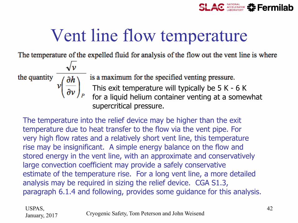
Vent line flow temperature
The temperature into the relief device may be higher than the exit temperature due to heat transfer to the flow via the vent pipe. For very high flow rates and a relatively short vent line, this temperature rise may be insignificant. A simple energy balance on the flow and stored energy in the vent line, with an approximate and conservatively large convection coefficient may provide a safely conservative estimate of the temperature rise. For a long vent line, a more detailed analysis may be required in sizing the relief device. CGA S1.3, paragraph 6.1.4 and following, provides some guidance for this analysis.
This exit temperature will typically be 5 K - 6 K for a liquid helium container venting at a somewhat supercritical pressure.
USPAS,
January, 2017 Cryogenic Safety, Tom Peterson and John Weisend 42
Vent line pressure drop
evaluation
USPAS,
January, 2017 Cryogenic Safety, Tom Peterson and John Weisend 43
USPAS,
January, 2017 Cryogenic Safety, Tom Peterson and John Weisend 44

USPAS,
January, 2017 Cryogenic Safety, Tom Peterson and John Weisend 45
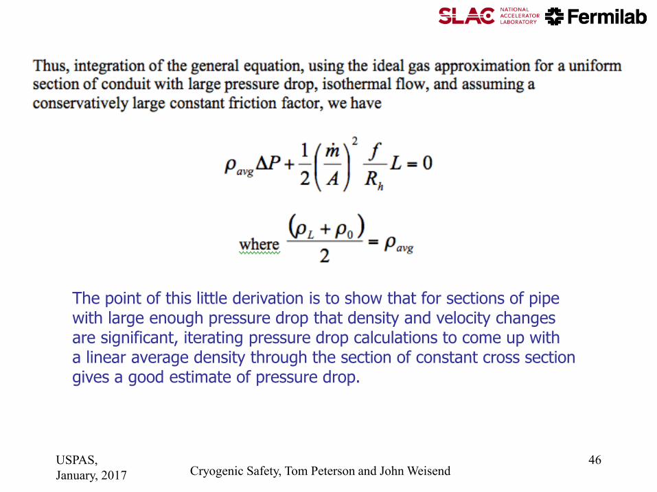
The point of this little derivation is to show that for sections of pipe with large enough pressure drop that density and velocity changes are significant, iterating pressure drop calculations to come up with a linear average density through the section of constant cross section gives a good estimate of pressure drop.
USPAS,
January, 2017 Cryogenic Safety, Tom Peterson and John Weisend 46

Pressure drop analysis,
working formula for round pipes
This is a form of the D'Arcy-Weisbach formula. With pressure drop
expressed as head loss, this is sometimes called simply the Darcy formula. (Note that delta-P changed signs here, to a positive number.)
USPAS,
January, 2017 Cryogenic Safety, Tom Peterson and John Weisend 47

Rupture disk and
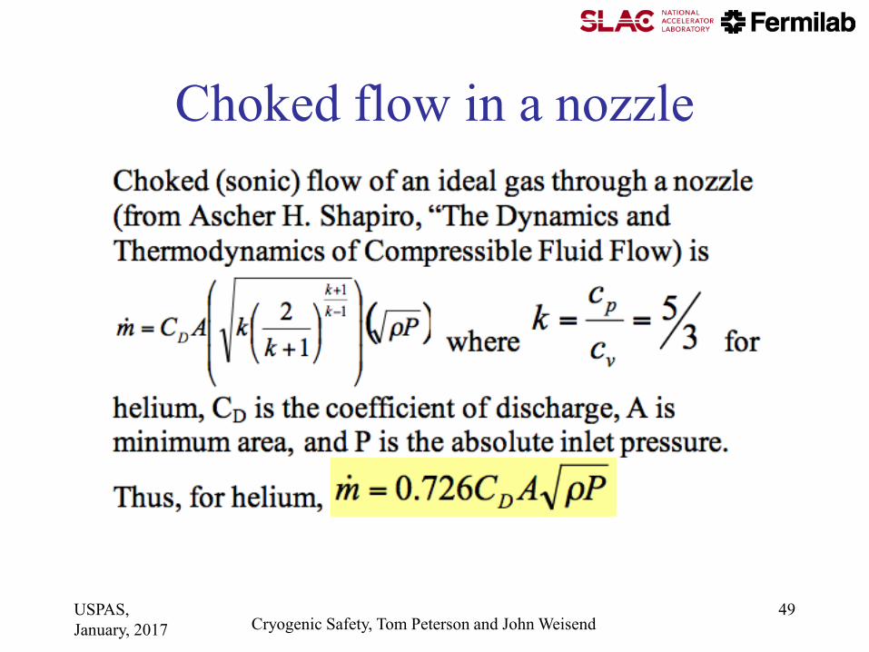
relief valve sizing • Flow will typically be choked (sonic) or nearly
choked in a relief valve or rupture disk
– Inlet pressure is at least 15 psig (1 atm gauge) for
ASME approved relief devices
– Discharge is to atmosphere
• This makes analysis relatively simple
– Relief valve catalogues and rupture disk catalogues
have good, practical working formulas and charts for
sizing relief devices
USPAS,
January, 2017 Cryogenic Safety, Tom Peterson and John Weisend 48
Choked flow in a nozzle
USPAS,
January, 2017 Cryogenic Safety, Tom Peterson and John Weisend 49
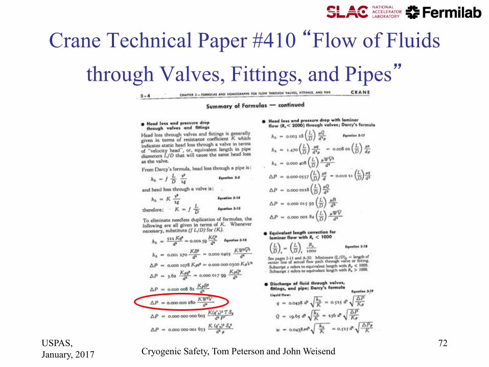
Crane Technical Paper #410
• Crane Technical Paper #410 “Flow of Fluids through Valves, Fittings, and Pipes”
• A classic reference, still available in updated forms
• Contains many forms of Bernoulli Equation and other formulas for both compressible and incompressible flow
• Relief valve and rupture disk catalogue formulas often reference Crane Technical Paper #410
• My only criticism (and strictly my personal opinion) -- I do not like the incorporation of unit conversions into formulas, which is too common in these engineering
handbooks
USPAS,
January, 2017 Cryogenic Safety, Tom Peterson and John Weisend 50

Relief devices
• For cracking pressures of 15 psig or higher,
ASME-approved (UV- or UD-stamped)
pressure relief devices may be used.
• For vessels with a differential pressure of
more than 15 psid within the vacuum jacket
but a gauge pressure of less than 15 psig,
ASME-approved reliefs are not available.
USPAS,
January, 2017 Cryogenic Safety, Tom Peterson and John Weisend 51

From the
BS&B
rupture
disk
catalogue
USPAS,
January, 2017 Cryogenic Safety, Tom Peterson and John Weisend 52

Rupture disks
• Various types, some pre-etched or with knife edge, or failure in collapse (pressure on the dome) and other designs and materials
– Difficult to set a precise opening pressure
• A last resort device since they do not close
– You don’t want these opening in normal operations
– Switching valves available for dual disks such that one can be replaced while the other holds pressure and provides protection
• Inexpensively provide very large capacity, so typical for the worst-case loss of vacuum
– Operational reclosing relief valves set at a safely lower pressure
(80% of RD or less) prevent accidental opening of the rupture disk
USPAS,
January, 2017 Cryogenic Safety, Tom Peterson and John Weisend 53
Relief valves
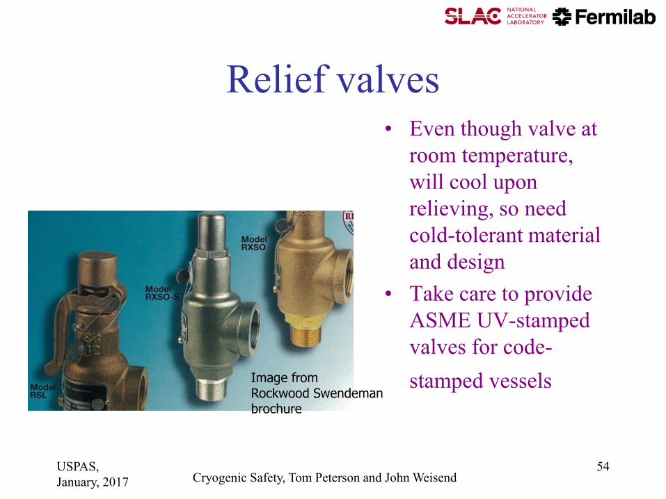
Image from Rockwood Swendeman brochure
• Even though valve at
room temperature,
will cool upon
relieving, so need
cold-tolerant material
and design
• Take care to provide
ASME UV-stamped
valves for code-
stamped vessels
USPAS,
January, 2017 Cryogenic Safety, Tom Peterson and John Weisend 54

Relief valves
• Sizing best done via valve manufacturer
information
– Shape of valve body, type of plug make sizing
unique to the valve design
– Manufacturers certify flow capacity for UV-
stamped (ASME approved) valves
USPAS,
January, 2017 Cryogenic Safety, Tom Peterson and John Weisend 55

Venting system analysis example
• The following spreadsheet shows a stepwise pressure drop analysis through a venting system
– Piping to a rupture disk via various straight lengths and fittings
– Rupture disk
– Piping downstream of the rupture disk
• A piecewise analysis such as in this Excel spreadsheet can be quite good since isothermal flow and the use of average density are good assumptions for analysis within each piece of conduit, which tend to be relatively short
USPAS,
January, 2017 Cryogenic Safety, Tom Peterson and John Weisend 56

Sample spreadsheet for large pressure drop
USPAS,
January, 2017 Cryogenic Safety, Tom Peterson and John Weisend 57

More examples • We have talked about relief systems
• Venting for the loss of vacuum to air incident with associated high heat flux and venting flow rate, combined with a low MAWP, can be the determining factor for pipe sizes all the way into the cryostat (not just the pipes connecting to the reliefs)
• Superconducting RF cavity helium vessels have these traits
– Low MAWP of as little as 1 bar gauge due to the delicate nature of the RF cavity
– Large bare metal surface area for air condensation within the
cavity vacuum, on the RF cavity surface
• The following examples illustrate some of these design issues
USPAS,
January, 2017 Cryogenic Safety, Tom Peterson and John Weisend 58

Cryomodule Pipe Sizing Criteria • Heat transport from cavity to 2-phase pipe
– 1 Watt/sq.cm. is a conservative rule for a vertical pipe (less heat flux with horizontal lengths)
• Two phase pipe size
– 5 meters/sec vapor “speed limit” over liquid
– Not smaller than nozzle from helium vessel
• Gas return pipe (also serves as the support pipe in TESLA-style CM)
– Pressure drop < 10% of total pressure in normal operation
– Support structure considerations
• Loss of vacuum venting P < cold MAWP at cavity
– Path includes nozzle from helium vessel, 2-phase pipe, may include gas return pipe, and any external vent lines
USPAS,
January, 2017 Cryogenic Safety, Tom Peterson and John Weisend 59

9-cell niobium
RF cavity
Cavity vacuum Helium space
Titanium
helium vessel
Helium port
Particle
beam
Tuning
bellows NbTi
transition
Superconducting RF Helium Vessel
USPAS,
January, 2017 Cryogenic Safety, Tom Peterson and John Weisend 60

Dressed cavity 650 MHz.
(proposal) with MC cold-part
Ti Helium vessel OD- 450.0 mm
Ti 2-Phase pipe ID- 161.5 mm
Ti 2-Phase chimney ID- 95.5 mm
USPAS,
January, 2017 Cryogenic Safety, Tom Peterson and John Weisend 61

Stand-alone
cryomodule
schematic
USPAS,
January, 2017 Cryogenic Safety, Tom Peterson and John Weisend 62
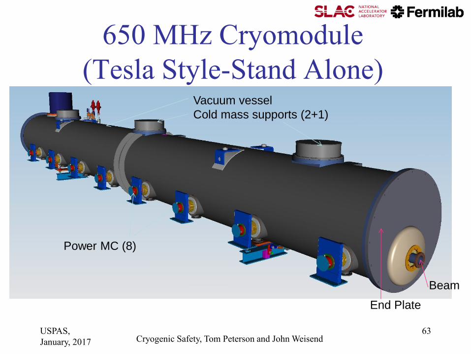
End Plate
Beam
650 MHz Cryomodule
(Tesla Style-Stand Alone)
Power MC (8)
Vacuum vessel
Cold mass supports (2+1)
USPAS,
January, 2017 Cryogenic Safety, Tom Peterson and John Weisend 63

Page 64
-48” vacuum vessel
300 mm pipe
-80K shield, pipes:
(Nom: 35mm-ID)
-Warm up-cool down
pipe (nom 25mm ID)
-4K return pipe
(nom 25mm ID)
-650 MC
-Thermal intercept
to MC 80k & 4K
-2-Phase pipe
(161mm-ID)
-80K Forward pipe
-4K Forward pipe
(?)
-Thermal intercept
2-phase pipe to
300mm pipe (?)
X-Y section
USPAS,
January, 2017 Cryogenic Safety, Tom Peterson and John Weisend 64

Page 65
Heat exchanger
(Location on the
middle of CM650??)
300mm pipe
Cryo-feed snout with
cryogenic connections
(Location on the
middle of CM650??)
Gate Valve
650 MHz cryomodule.
End plate not shown.
Access to bayonet
connections
Access to
HX and U-turn
connections
USPAS,
January, 2017 Cryogenic Safety, Tom Peterson and John Weisend 65

Cryomodule requirements --
vessel and piping pressures
USPAS,
January, 2017 Cryogenic Safety, Tom Peterson and John Weisend 66

325 MHz loss of vacuum venting
Just a note from our design effort. We would like
for mechanical space reasons to use a
5-inch OD tube in our 325 MHz CM.
The practical limit then is 8 cavities
in series for emergency venting flow.
USPAS,
January, 2017 Cryogenic Safety, Tom Peterson and John Weisend 67

Note: a 3-inch air inlet hole results in a mass flow equivalent to ~ 8 beta=0.9 650 MHz
cavities. Checking the feasibility of venting a CM string of cavities with a large 2-phase
pipe. Looks OK but still need frequent cross-connects to a larger pipe.
USPAS,
January, 2017 Cryogenic Safety, Tom Peterson and John Weisend 68

650 MHz Cryomodule Design, 21 Feb 2011 Page 69 USPAS,
January, 2017 Cryogenic Safety, Tom Peterson and John Weisend 69
A comment about engineering
• Note that the previous slides showing some
examples of cryomodule pipe sizing for
emergency venting situations could have
been placed in the cryomodule design
lecture.
• Off-design allowances and safety
considerations are part of the design
process!
USPAS,
January, 2017 Cryogenic Safety, Tom Peterson and John Weisend 70

Subatmospheric systems
• In cases where normal operation is
subatmospheric, a rupture disk is generally
preferred, since a valve may allow air to
leak back into the system.
• Back leakage must be prevented not only to
avoid contamination of the helium during
normal operation, but because frozen air in
a vent line could block the relief flow path.
USPAS,
January, 2017 Cryogenic Safety, Tom Peterson and John Weisend 71
Crane Technical Paper #410 “Flow of Fluids
through Valves, Fittings, and Pipes”
USPAS,
January, 2017 Cryogenic Safety, Tom Peterson and John Weisend 72

Where P is pressure drop in psi, V is the specific volume (in3/lbm),
K is the total resistance coefficient = fL/d so is dimensionless, W is
the mass flow rate (lbm/hr), and d is the pipe inner diameter (in).
For example from previous list
Compare to
from slide 34 -- no unit conversions, and a different definition of
friction factor. Note! Some sources define f based on hydraulic
radius and some on diameter, a factor 4 difference for pipes!
USPAS,
January, 2017 Cryogenic Safety, Tom Peterson and John Weisend 73

An example from CGA S-1.3—2005 for evaluation of
the discharge temperature and
effective latent heat
(or “pseudo latent heat”)
USPAS,
January, 2017 Cryogenic Safety, Tom Peterson and John Weisend 74

Maximum, so venting temperature is about 5.40 K and effective latent heat is 15.1 J/g
USPAS,
January, 2017 Cryogenic Safety, Tom Peterson and John Weisend 75

Another source of
pseudo latent heat -- a
plot of effective latent
heat of helium as a
function of temperature
and pressure from R.H.
Kropschot, et. al.,
“Technology of Liquid
Helium,” NBS
Monograph 111
USPAS,
January, 2017 Cryogenic Safety, Tom Peterson and John Weisend 76

Fire relief sizing (CGA S-1.3—2005
paragraph 6.3.2) -- a suggestion • I received a suggestion from an engineering note
review panel at Fermilab with which I agree:
– “For the fire condition, it is suggested that the argument be made that this case is identical to the loss of cryostat vacuum since it is an uninsulated vessel. For an uninsulated vessel, the heat load to the vessel is driven by air condensation/freezing as opposed to insulated vessels considering a temperature gradient across the insulation resulting gas conduction. The fact that there is a fire externally does not affect the vessel since it is shielded from the radiation; only the resulting letting up of the cryostat vacuum and resulting condensation and/or freezing drives the relieving requirements.”
USPAS,
January, 2017 Cryogenic Safety, Tom Peterson and John Weisend 77

Example from an engineering
note analysis for a
superconducting RF cavity
vertical test dewar
USPAS,
January, 2017 Cryogenic Safety, Tom Peterson and John Weisend 78

Vertical Test System (VTS)
USPAS,
January, 2017 Cryogenic Safety, Tom Peterson and John Weisend 79

From CGA S-1.3
From an analysis like on slide 75
to obtain effective latent heat
Note comparison of loss of cavity vacuum with condensation on smaller area of bare metal to loss of insulating vacuum with smaller heat flux on larger area.
USPAS,
January, 2017 Cryogenic Safety, Tom Peterson and John Weisend 80

Fermilab parallel plate vacuum relief
USPAS,
January, 2017 Cryogenic Safety, Tom Peterson and John Weisend 81
Vacuum relief
• Typically very low pressure
– Vacuum vessel not a code-stamped pressure vessel, so < 0.5 - 1 atm MAWP
– Flow may be subsonic
– Valve not officially approved
– Sizing may be difficult, must be conservative
• But the most difficult task may be deciding on the worst-case incident for which the vacuum valve must be sized
USPAS,
January, 2017 Cryogenic Safety, Tom Peterson and John Weisend 82
ODH analysis
• Reference: Fermilab ES&H manual
(FESHM) Chapter 5064
USPAS,
January, 2017 Cryogenic Safety, Tom Peterson and John Weisend 83
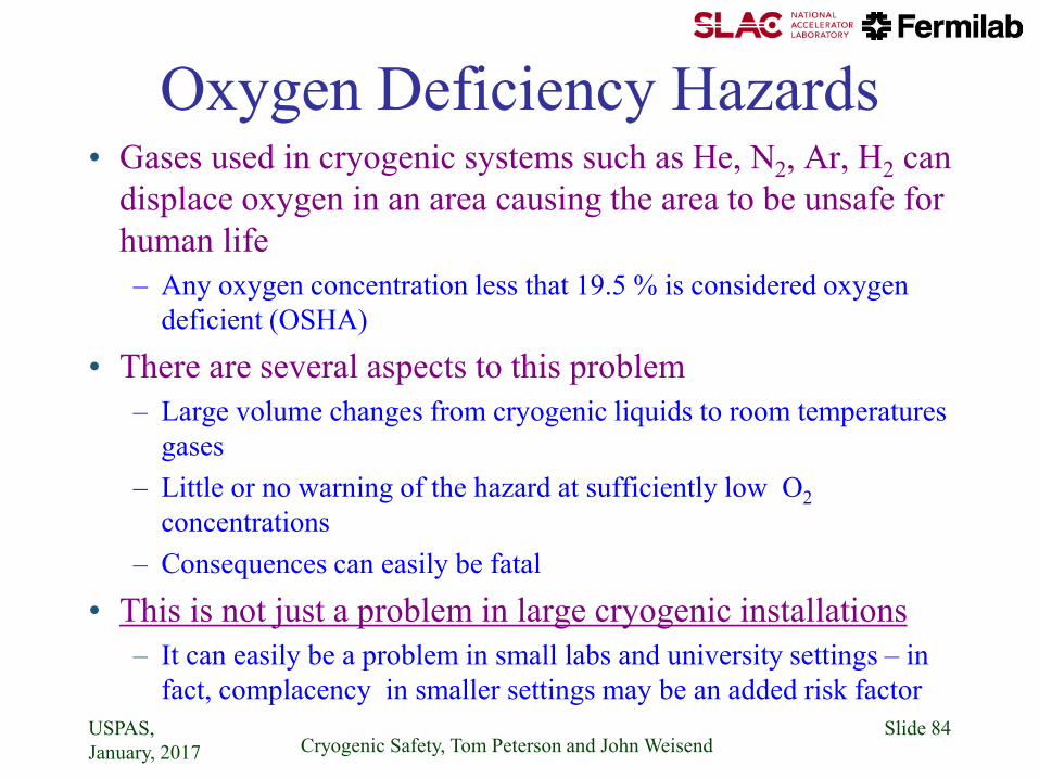
Oxygen Deficiency Hazards • Gases used in cryogenic systems such as He, N2, Ar, H2 can
displace oxygen in an area causing the area to be unsafe for
human life
– Any oxygen concentration less that 19.5 % is considered oxygen
deficient (OSHA)
• There are several aspects to this problem
– Large volume changes from cryogenic liquids to room temperatures
gases
– Little or no warning of the hazard at sufficiently low O2
concentrations
– Consequences can easily be fatal
• This is not just a problem in large cryogenic installations
– It can easily be a problem in small labs and university settings – in
fact, complacency in smaller settings may be an added risk factor
USPAS,
January, 2017 Cryogenic Safety, Tom Peterson and John Weisend Slide 84

Oxygen Deficiency Hazards
• Recall the large volume increase between a
cryogenic liquid and its gas at 300 K and 1
atmosphere • Even small amounts of liquid can be a hazard is the if
released into a small enough volume e.g. small rooms,
elevators or cars
• For example 160 liters of LN2 is sufficient to completely
replace all the air in a 19 x 19 x 10 ft room
USPAS,
January, 2017 Cryogenic Safety, Tom Peterson and John Weisend Slide 85

Volume Changes for Cryogenic Fluids
from normal boiling point to 300 K & 1 atm
USPAS,
January, 2017 Cryogenic Safety, Tom Peterson and John Weisend Slide 86
Substance Vgas/Vliquid
Helium 701
Parahydrogen 788
Neon 1341
Nitrogen 646
Argon 779
CO2 762
Oxygen 797

Consequences of Oxygen Deficiency
Cryogenic Safety, Tom Peterson and John Weisend Slide 87 USPAS,
January, 2017
Volume
% Oxygen
(at sea level)
Effect
17 Night vision reduced
Increased breathing volume
Accelerated heartbeat
16 Dizziness
Reaction time for novel tasks doubled
15 Impaired attention
Impaired judgment
Impaired coordination
Intermittent breathing
Rapid fatigue
Loss of muscle control
12 Very faulty judgment
Very poor muscular coordination
Loss of consciousness
Permanent brain damage
10 Inability to move
Nausea
Vomiting
6 Spasmodic breathing
Convulsive movements
Death in 5-8 minutes

Approximate time of useful consciousness
for a seated subject at sea level vs % O2
Cryogenic Safety, Tom Peterson and John Weisend Slide 88 USPAS,
January, 2017
At low enough
concentrations you can
be unconscious in less
that a minute with NO
warning
This is one of the things
that makes ODH so
dangerous & frequently
results in multiple
fatalities
Its also why inhaling He
from balloons is
dangerous

ODH Safety Basics
• Understand the problem: This lecture
• Determine level of risk
• Apply mitigations to reduce the risk
• Have a plan to respond to emergencies
• ALL users of cryogenic fluids no matter how
small should analyze their risk and consider
mitigations
– At a minimum, everyone should be trained to
understand the hazard
USPAS,
January, 2017 Cryogenic Safety, Tom Peterson and John Weisend Slide 89
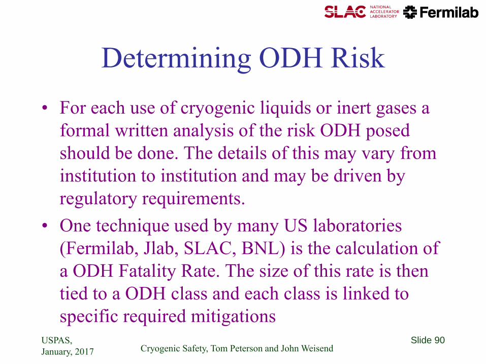
Determining ODH Risk
• For each use of cryogenic liquids or inert gases a
formal written analysis of the risk ODH posed
should be done. The details of this may vary from
institution to institution and may be driven by
regulatory requirements.
• One technique used by many US laboratories
(Fermilab, Jlab, SLAC, BNL) is the calculation of
a ODH Fatality Rate. The size of this rate is then
tied to a ODH class and each class is linked to
specific required mitigations
USPAS,
January, 2017 Cryogenic Safety, Tom Peterson and John Weisend Slide 90

ODH Fatality Rates
USPAS,
January, 2017 Cryogenic Safety, Tom Peterson and John Weisend Slide 91
i
n
i
iFP
1
where: = the ODH fatality rate (per hour)
Pi = the expected rate of the ith event (per
hour), and
Fi = the probability of a fatality due to event i.
Sum up for all n possible events

ODH Fatality Rates
• Probability of an event ( Pi ) may be based
on institutional experience or on more
general data (see handouts)
• Probability of a given event causing a
fatality ( Fi ) is related to the lowest possible
oxygen concentration that might result from
the event
USPAS,
January, 2017 Cryogenic Safety, Tom Peterson and John Weisend Slide 92

Fi vs. Oxygen Concentration (note limits) from “Cryogenic and Oxygen Deficiency Hazard Safety: ODH Risk Assessment
Procedures” SLAC ES&H Manual
USPAS,
January, 2017 Cryogenic Safety, Tom Peterson and John Weisend Slide 93
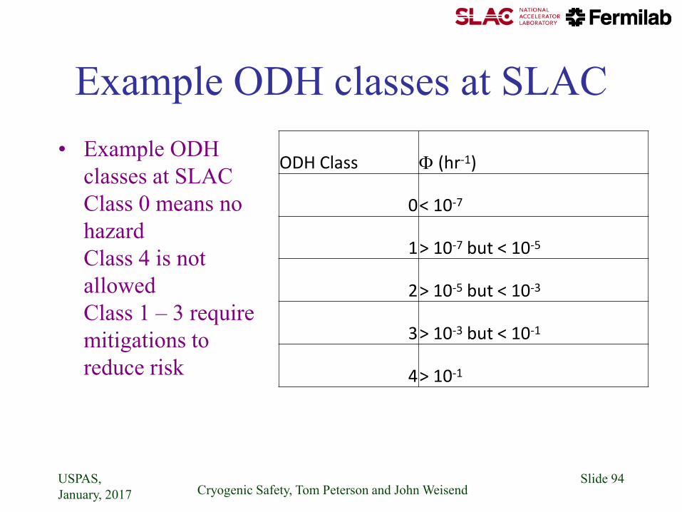
Example ODH classes at SLAC
• Example ODH
classes at SLAC
Class 0 means no
hazard
Class 4 is not
allowed
Class 1 – 3 require
mitigations to
reduce risk
USPAS,
January, 2017 Cryogenic Safety, Tom Peterson and John Weisend Slide 94
ODH Class (hr-1)
0 < 10-7
1 > 10-7 but < 10-5
2 > 10-5 but < 10-3
3 > 10-3 but < 10-1
4 > 10-1
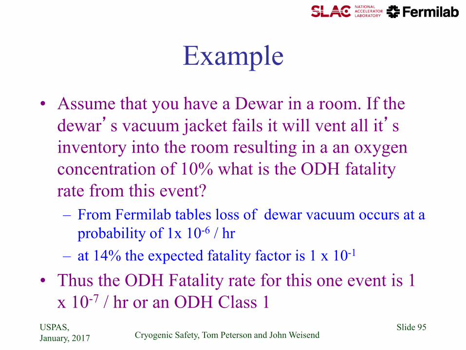
Example
• Assume that you have a Dewar in a room. If the
dewar’s vacuum jacket fails it will vent all it’s
inventory into the room resulting in a an oxygen
concentration of 10% what is the ODH fatality
rate from this event?
– From Fermilab tables loss of dewar vacuum occurs at a
probability of 1x 10⁻⁶ / hr
– at 14% the expected fatality factor is 1 x 10⁻¹
• Thus the ODH Fatality rate for this one event is 1
x 10-7 / hr or an ODH Class 1
USPAS,
January, 2017 Cryogenic Safety, Tom Peterson and John Weisend Slide 95

ODH Mitigations • Best solution: Eliminate the hazard by design choices
– Reduce inventory of cryogenic fluids & compressed gases
– Don’t conduct cryogenic activities in small spaces
– Don’t use LN2 underground
• Training
– Everyone working in a possible ODH area should be made aware
of the hazard and know what to do in the event of an incident or
alarm
• This includes periodic workers such as security staff, custodial staff
and contractors
• Visitors should be escorted
• Signs
– Notify people of the hazard and proper response
– Indicate that only trained people are authorized to be there
USPAS,
January, 2017 Cryogenic Safety, Tom Peterson and John Weisend Slide 96

Example 2: Summary Analysis for Fermilab MTA Hall
USPAS,
January, 2017 Cryogenic Safety, Tom Peterson and John Weisend Slide 97
Table 1 MTA Hall ODH Risk Analysis Revision 2008with fan in FAST and available for ventilation
Volume, V, cubic feet Ventilation, Q, cfm
14063 1800
CV or TYPE OF P GROUP Fan Availability R Q O2 F Ø ODH
ITEM Comment Size FAILURE # FAIL RATE FAIL RATE RATE leak rate vent rate Conc. Fatality Factor ODH Rate Class
(in.) (events/hr) (events/hr) (events/hr) (scfm) (scfm) (%) (fatality/event) (fatality/hr)
1 Helium circuit
a. LHe Supply Line piping/tubing N/A Rupture Fluid line 1 2.00E-08 2.00E-08 9.99E-01 1859 1800 0.00 1 2.00E-08 0
b. LHe Venting Line piping/tubing N/A Rupture pipe 1 1.00E-09 1.00E-09 9.99E-01 596 1800 14.05 6.67626E-05 6.67E-14 0
c. Solenoid magnet Helium Vessel piping/tubing N/A Rupture Dewar 1 1.00E-06 1.00E-06 9.99E-01 818 1800 11.46 0.006207737 6.20E-09 0
d. Transfer line cool-down Valve PVC1 2.3 Leakage or failure 1 1.00E-08 1.00E-08 9.99E-01 1859 1800 0.00 1 9.99E-09 0
e. Transfer line cool-down by-pass Valve PVC2 2.3 Leakage or failure 1 1.00E-08 1.00E-08 9.99E-01 1859 1800 0.00 1 9.99E-09 0
f. LHe Isolation Ball Valve on Solenoid MV1 34 Leakage or failure 1 1.00E-08 1.00E-08 9.99E-01 1859 1800 0.00 1 9.99E-09 0
g. Solenoid Liquid Helium Vent Valve EVVT 3.8 Leakage or failure 1 1.00E-08 1.00E-08 9.99E-01 530 1800 14.82 1.73514E-05 1.73E-13 0
h. Helium Vessel Rupture Disk Relief RD1 Leakage or rupture 1 2.00E-08 2.00E-08 9.99E-01 582 1800 14.21 5.01649E-05 1.00E-12 0
i. Helium Vessel Relief SV1 & SV2 Leakage or rupture 2 2.00E-08 4.00E-08 9.99E-01 259 1800 17.98 6.86225E-08 2.74E-15 0
j. Helium Vent Check Valve CVH1 Leakage or rupture 1 1.00E-08 1.00E-08 9.99E-01 140 1800 19.37 0 0.00E+00 0
k. Helium Cool-down Check Valve CVH2 Leakage or rupture 1 1.00E-08 1.00E-08 9.99E-01 140 1800 19.37 0 0.00E+00 0
l. Helium Energy Saver Relief Valve SV8 N/A Leakage or rupture 1 2.00E-08 2.00E-08 9.99E-01 174 1800 18.97 0 0.00E+00 0
m. Check Valve - acoustic osci. CV4 Leakage or rupture 1 1.00E-08 1.00E-08 9.99E-01 1859 1800 0.00 1 9.99E-09 0
1.17E-06 6.62E-08
2 Nitrogen circuit
a. LN2 Supply Line piping/tubing Rupture Fluid line 1 2.00E-08 2.00E-08 9.99E-01 676 1800 13.11 0.000341874 6.83E-12 0
b. N2 Return Line piping/tubing Rupture pipe 1 1.00E-09 1.00E-09 9.99E-01 480 1800 15.40 6.25173E-06 6.25E-15 0
c. Magnet Nitrogen Vessel piping/tubing Rupture Dewar 1 1.00E-06 1.00E-06 9.99E-01 11 1800 20.87 0 0.00E+00 0
d. N2 vent Check Valve CVN2 Leakage or rupture 1 1.00E-08 1.00E-08 9.99E-01 65 1800 20.24 0 0.00E+00 0
1.03E-06 6.84E-12
3 Instrument gas circuit
a. N2 instrument Supply Line Rupture 1 1.00E-08 1.00E-08 9.99E-01 11 1800 20.87 0 0.00E+00 0
b. Solenoid Valve for PVC1 EVC1 Leakage or failure 1 5.00E-07 5.00E-07 9.99E-01 57 1800 20.34 0 0.00E+00 0
c. Solenoid Valve for PVC2 EVC2 Leakage or failure 1 3.42E-07 3.42E-07 9.99E-01 57 1800 20.34 0 0.00E+00 0
8.52E-07 0.00E+00
TOTAL 3.05E-06 ODH Class = 6.62E-08 0
M. Geynisman, AD/CRYO
The probability of ventilation failure is a summation of probabilities of components responsible for
turning the fan ON to FAST. We assume probabilities of failures:
P (power outage) = 1.0E-4 /hr per demand
P (ODH sensor) = 1.1E-4 /hr per demand
P (ODH chassis) = 3.0E-4 /hr per demand
P (motor fail to start) = 3.0E-4 /hr per demand
Thus the combined probability of failure to start the fan in FAST is 8.1E-4 /hr per demand. Thus fan
availability is (1-8.1E-4) = 0.9992 (close to 1).
1
n
i i
i
P F
ODH Mitigations --Ventilation • Ventilation systems to increase air exchange
and reduce the possibility of an oxygen
deficient atmosphere forming
– Warning If this approach is taken, the
ventilation system must now be treated as a
safety system with appropriate controls and
redundancies
• What happens during maintenance or equipment
failure?
• How do you know ventilation system is working?
USPAS,
January, 2017 Cryogenic Safety, Tom Peterson and John Weisend Slide 98
ODH Mitigations -- Monitors and Alarms
• A very common and effective mitigation. Commercial devices exist.
• Indicates when a hazard exists
• Very valuable in showing if a area has become dangerous during off hours
• Alarms generally set to trip at 19.5% Oxygen
• Alarms should include lights & horn as well as an indicator at entrance to area
• Alarms should register in a remote center (control room or fire dept) as well
• As a safety system it requires appropriate controls & backups (UPS, redundancy etc)
• In some cases personal monitors will add additional safety
USPAS,
January, 2017 Cryogenic Safety, Tom Peterson and John Weisend 99

Response to Alarms & Emergencies
• In the event of an alarm or other indication of a
hazard immediately leave the area
• Do not reenter the area unless properly trained and
equipped (e.g. supplementary air tanks)
– Don’t just run in to see what the problem is
• Only properly trained and equipped professionals
should attempt a rescue in an ODH situation
• Response to alarms should be agreed upon in
advance, documented and be part of training
USPAS,
January, 2017 Cryogenic Safety, Tom Peterson and John Weisend Slide 100
ODH Summary • Oxygen Deficiency is a significant hazard in cryogenic
installations both large and small. It must be taken
seriously
• Lethal conditions can exist without prior warning or
symptoms
• ODH can managed by awareness, analysis of risk and
appropriate mitigations
• Everyone working in a cryogenic facility should be aware
of the risk and know what to do in the event of a problem
• There is a significant amount of experience & help
available from laboratories and industry to reduce the
ODH risk
USPAS,
January, 2017 Cryogenic Safety, Tom Peterson and John Weisend Slide 101

Conclusions • Cryogenic vessels and piping generally fall under the scope of the
ASME pressure vessel and piping codes
• Protection against overpressure often involves not only sizing a rupture
disk or relief valve but sizing vent piping between those and the vessel,
and also perhaps further ducting downstream of the reliefs
• Loss of vacuum to air with approximately 4 W/cm2 heat flux on bare
metal surfaces at liquid helium temperatures can drive not only the
design of the venting system but pipe sizes within the normally
operational portions of the cryostat
• Piping stability due to forces resulting from pressure around expansion
joints is sometimes overlooked and may also significantly influence
mechanical design
USPAS,
January, 2017 Cryogenic Safety, Tom Peterson and John Weisend 102
References -- 1
• ASME Boiler & Pressure Vessel Code, 2007 Edition, July 1, 2007
– Primarily Section VIII, Division 1 and Division 2
• ASME B31.3-2008, Process Piping, ASME Code for Pressure Piping
• R. Byron Bird, Warren E. Stewart, Edwin N. Lightfoot, “Transport Phenomena,” John Wiley &Sons, 1960.
• S. W. VanSciver, “Helium Cryogenics,” Plenum Press, 1986.
• CGA S-1.3, “Pressure Relief Device Standards”, Compressed Gas Association, 2005.
USPAS,
January, 2017 Cryogenic Safety, Tom Peterson and John Weisend 103

References -- 2
• Fermilab’s ES&H Manual (FESHM) pressure vessel
standard, FESHM 5031
– http://esh-docdb.fnal.gov/cgi-bin/ShowDocument?docid=456
• FESHM Chapter 5031.6 - Dressed Niobium SRF Cavity
Pressure Safety
– And associated document: “Guidelines for the Design,
Fabrication, Testing and Installation of SRF Nb Cavities,”
Fermilab Technical Division Technical Note TD-09-005
– http://esh-docdb.fnal.gov/cgi-bin/ShowDocument?docid=1097
USPAS,
January, 2017 Cryogenic Safety, Tom Peterson and John Weisend 104

References -- 3 • W. Lehman and G. Zahn, “Safety Aspects for LHe
Cryostats and LHe Transport Containers,” ICEC7, London, 1978
• G. Cavallari, et. al., “Pressure Protection against Vacuum Failures on the Cryostats for LEP SC Cavities,” 4th Workshop on RF Superconductivity, Tsukuba, Japan, 14-18 August, 1989
• M. Wiseman, et. al., “Loss of Cavity Vacuum Experiment at CEBAF,” Advances in Cryogenic Engineering, Vol. 39, 1994, pg. 997.
• T. Boeckmann, et. al., “Experimental Tests of Fault Conditions During the Cryogenic Operation of a XFEL
Prototype Cryomodule,” DESY.
USPAS,
January, 2017 Cryogenic Safety, Tom Peterson and John Weisend 105

References -- 4 • E. G. Brentari, et. al., “Boiling Heat Transfer for Oxygen,
Nitrogen, Hydrogen, and Helium,” NBS Technical Note
317, 1965.
• NBS Technical Note 631, “Thermophysical Properties of
Helium-4 from 2 to 1500 K with Pressures to 1000
Atmospheres”, 1972.
• Vincent D. Arp and Robert D. McCarty, “Thermophysical
Properties of Helium-4 from 0.8 to 1500 K with Pressures
to 2000 Atmospheres,” National Institute of Standards and
Technology (NIST) Technical Note 1334, 1989.
• HEPAK (by Cryodata, Inc.)
USPAS,
January, 2017 Cryogenic Safety, Tom Peterson and John Weisend 106

References -- 5
• “Flow of Fluids through Valves, Fittings, and
Pipes,” Crane Technical Paper #410.
• R.H. Kropschot, et. al., “Technology of Liquid
Helium,” NBS Monograph 111
• Ascher H. Shapiro, “The Dynamics and
Thermodynamics of Compressible Fluid Flow,”
Wiley, 1953.
USPAS,
January, 2017 Cryogenic Safety, Tom Peterson and John Weisend 107


