Page 1
1
MM 396: B.Tech Seminar
Cryogenic Treatment of Tool Steel
By
Tushar Mamodia
Roll No. 11D110015
Rahul Maghanti
Roll No. 110110061
Supervisor
Prof. Dipti Gupta
Department of Metallurgical Engineering and Materials Science
INDIAN INSTITUTE OF TECHNOLOGY BOMBAY
(March 2014)
Page 2
2
INDEX
CERTIFICATE 1
ABSTRACT 3
CHAPTER-1 TOOL STEEL & HIGH SPEED STEEL
1.1 Background 4
1.2 Technological development 4
1.3 Surface treatments 5
CHAPTER-2 CRYOGENICS
2.1 Introduction 6
2.2 History 6
2.3 Cryogenic Processing 6
CHAPTER-3 CRYOGENIC TREATMENT
3.1 Introduction
3.1.1 Classification of Cryogenic Treatment 7
3.1.2 Theories behind Cryogenic Treatment 7
3.2 The making of liquid Nitrogen 9
3.3 Cryogenic treatment procedure
3.3.1 Experimental Procedure 10
3.3.2 Typical Cryogenic Cycle 11
CHAPTER-4 METALLURGICAL EVOLUTIONS
4.1 Microstructure
4.1.1 Experiments 12
4.1.2 Results and Discussions 12
4.2 Crystallographic Textures 19
4.2.1 Introduction 14
4.2.2 Polycrystalline Plasticity background
4.2.2.1 Single Crystal Constitutive Equation 14
4.2.2.2 Linking Assumption 14
CHAPTER-5 EXPERIMENTAL DETAILS
5.1 Effects of Cryogenic Treatment
5.1.1 Microstructural Evaluation 15
5.1.2 Mechanical Properties 18
5.2 Laboratory tests
5.2.1 Flank Wear Test 19
5.2.2 Sliding Wear Test 20
5.2.3 Hardness Test 21
CHAPTER-7 CONCLUSION 22
REFERENCES 23
DECLARATION 25
Page 3
3
ABSTRACT
We look into brief introduction of cryogenic treatment. Our focus throughout the report is
more on cryogenic treatment of tool steel and high speed steel. In metal forming industry
tools are exposed to very complex and rough surface conditions, which are the result of
different effects (mechanical, thermal and chemical) and thus require well defined
mechanical properties. Different approaches are followed to increase the surface properties of
tool steels. The surface hardening treatments of steel has shown significant improvement of
various properties including wear and fatigue resistance.
Cryogenic treatment is yet another approach acknowledged by some to extend the tool life of
many cutting tools. We will describe the complete procedure and investigate the effects on
the metallurgical changes in the tool steel. However real mechanisms behind the better
performance of tools are still in doubt. Studies in the given references on cryogenically
treated tool steel shows microstructural changes in material that can influence the tool life.
However little is gained from the experimental results showing involvement of carbide
precipitations. Cryogenic treatments of carbides has yet to be extensively studied.
Page 4
4
CHAPTER-1 TOOL STEEL
1.1 Background
Metal cutting process form the basis of engineering industry and is involved either
directly or indirectly in the manufacture of nearly every product we use in our daily life. Over
the years of demand and economic competition a lot of research is done leading to the
increased performance of tools and increase in overall productivity.
As manufacturers always need new materials that are lighter, stronger and more fuel
efficient, it is clear that such materials must be so developed to give highest productivity. The
most important part of designing of such cutting tools is material construction by careful
selection. The properties that these tool materials must have are as follows-
Performance at elevated temperatures during high speed cutting operations
High resistance to brittle fracture
Resistance to thermal and mechanical shock
Easily fabricated and Cost effective
Development in the field of cutting tools is more focused by the extreme conditions of
stress and temperature produced at the tool-work piece interface. Due to the presence of tool
at such conditions wear and tear of tool occurs by complex mechanisms ie. Abrasive wear,
chipping at the cutting edge, thermal cracking, etc.
1.2 Technological Developments
Tool materials have improved rapidly during last few decades. Development includes
from manufacturing of carbon tool steels, High speed steels and cast alloys to carbides and
ceramics. Till 1990 machining was done by plain carbon steel, shortly after 1990 high speed
steel were introduced. Ceramic tools exhibit very high hardness and wear resistance
facilitating the use of higher cutting speeds.
UCON a new tool material consisting of columbium, tungsten, titanium permits 60%
increase in the cutting speed when compared with tungsten carbide. Cubic Boron Nitride with
hardness next to diamond which is claimed to give speed 5 to 8 times that of carbide can be
used to cut hardened materials. Polycrystalline diamond bonded to tungsten carbide substrate
has been successfully employed for machining non-ferrous materials. [19]
Tradition material such as high speed steel continue to undergo improvement in
properties by modification in the compositions and processing techniques. As a result of these
technological advances the high speed steel is still surviving the competition from ceramics
and carbides. Carbide because of ability to retain strength at high temperature more hardness
and an economical price is a much logical choice of many industries. However with some
outer surface treatments the life and surface properties can be enhanced to a new level.
Page 5
5
1.3 Surface Treatments
Due to advances in the manufacturing technologies there is a parallel growth of
surface treatments for cutting tools. No single treatment will solve every problem and thus
their use should be restricted to the application as well. These treatments will change the
surface of tool materials to:
Control friction and wear
Improve corrosion resistance
Change physical properties
Vary appearance (texture)
Reduce manufacturing cost
Common surface treatments can be divided into two major categories:
a) Treatments that cover surfaces
b) Treatments that alter surfaces
Treatments covering surfaces:
Organic coatings such as paints, cements, laminates and fused powders
Inorganic coatings such as electroplating or coating of thin film using CVD(chemical
vapor deposition) or PVD(physical vapor deposition)
Treatments altering surfaces:
High energy treatments such as ion implanting and laser fusion
Diffusion treatments such as nitriding, carburizing and thermal diffusion
Special treatments such as cryogenic, magnetic and sonic treatment
Cryogenic treatment is an inexpensive permanent treatment which follows the conventional
heat treatment cycle. It is found that the life span of the cutting tool is increased along with
the hardness and toughness by the cryogenic treatment. [18] Over the past few years the
research interest has changed to the effect change of parameters (cutting speed, depth of cut
and feed) during cryogenic treatment.
Page 6
6
CHAPTER-2 CRYOGENICS
2.1 Introduction
Cryogenics is defined as the branches of physics and engineering that study very low
temperatures, how to produce them, and how materials behave at those temperatures. The
word Cryogenics is derived from the Greek words 'Kryos" (meaning cold) and "Genes"
(meaning born). The word cryogenics literally means "the production of icy cold".
2.2 History
The field of cryogenics advanced during World War II when scientists found that
metals frozen to low temperatures showed more resistance to wear [10, 22, 34]. Until the end
of 1960s, attempts made to perform cryogenic processing resulted in cracking of components.
The cryogenic treatment system developed by Ed Busch in the late 1960s with a temperature
feedback control on cooling and heating rates allows to perform it effectively. The research
about Cryogenics has been validated during the 1980s by the first request in machine tools.
[17] [16]
Latter with research and development, computerized temperature control systems
have been developed to get crack less cryogenic treated components to achieve maximum
benefits. [15] [14] In 1942, researchers at the Massachusetts Institute of Technology found
that a certain favorable combination of properties could be achieved only by including a cold
treatment in the processing cycle of a tool steel. Several years later, moderate to large
improvements in tool steel performance were reported when cold treatments were used.
2.3 Cryogenic Processing
The cryogenic processing is modification of a material or component using cryogenic
temperatures. The workers at the National Institute of Standards and Technology at Boulder,
Colorado have chosen to consider the field of cryogenics as that involving temperatures
below –180C(93.15 K) [13]. Cryogenic processing makes changes to the crystal structure of
materials.
Deep sub-zero (much below 0C) processing of metals and alloys is a deep stress
relieving technology. The third law of thermodynamics states that entropy is zero at absolute
zero temperature. Cryogenic processing uses this principle to relieve stresses in the material.
The materials are subjected to extremely low temperatures for long period of time leading to
development of equilibrium. This leads to decrease in defects in the material and it attains a
minimum entropy state. [12]
Cryogenic processing will not in itself harden metal like quenching and tempering. It
is not a substitute for heat-treating. It is an addition to heat-treating. Most alloys will not
show much of a change in hardness due to cryogenic processing. The material will have to be
cryogenically treated followed by tempering to gain the hardness and toughness.
Page 7
7
CHAPTER-3 CRYOGENIC TREATMENT
3.1 Introduction
The thermal treatment of metals must certainly be regarded as one of the most
important developments of the industrial age. One of the modern processes being used to
treat metals (as well as other materials) is cryogenic tempering. Cryogenic treatment is a one-
time permanent treatment process and it affects the entire cross-section of the material.
Usually done at the end of conventional heat treatment process but before tempering. [11]
Also it is not a substitute process but rather a supplement to conventional heat treatment
process.
3.1.1 Classification of Cryogenic Treatment
Cryogenic treatment has been classified into shallow cryogenic treatment (SCT) and
deep cryogenic treatment (DCT) depending upon the temperatures in which the material is
treated: [10]
SCT- tool steel is keep in freezer at 193K for 5 h and then exposed to RT
DCT- material is brought down to 77K at 1.26 K/min, held there for 24 h and brought
back to RT at 0.63 K/min.
3.1.2 Theories for Cryogenic Treatment
The researchers have devised following possible theories responsible for the changes
in properties of tool steel after cryogenically treated:
Complete transformation of retained austenite into martensite [8] [9]
Precipitation of microscopic carbides into martensite [4] [7]
Fig 1. Microstructures showing transformation of retained austenite to martensite [20]
The martensite formed is darkened by subsequent tempering, the light areas are martensite plus retained
austenite. Steel M-182, etched with 1% nital + 1 % zephiran chloride. X750.
(a) transformed at 265 C, 62% martensite;
(b) transformed at 240 C, 81% martensite;
(c) transformed at 210 C, 93% martensite
Page 8
8
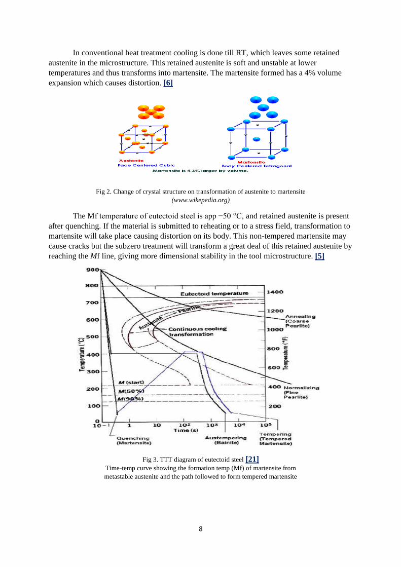
In conventional heat treatment cooling is done till RT, which leaves some retained
austenite in the microstructure. This retained austenite is soft and unstable at lower
temperatures and thus transforms into martensite. The martensite formed has a 4% volume
expansion which causes distortion. [6]
Fig 2. Change of crystal structure on transformation of austenite to martensite (www.wikepedia.org)
The Mf temperature of eutectoid steel is app −50 °C, and retained austenite is present
after quenching. If the material is submitted to reheating or to a stress field, transformation to
martensite will take place causing distortion on its body. This non-tempered martensite may
cause cracks but the subzero treatment will transform a great deal of this retained austenite by
reaching the Mf line, giving more dimensional stability in the tool microstructure. [5]
Fig 3. TTT diagram of eutectoid steel [21] Time-temp curve showing the formation temp (Mf) of martensite from
metastable austenite and the path followed to form tempered martensite
Page 9
9
The influence of precipitated particles is shown by yet another research done on M2
steel by varying the cryogenic cycles. Their research involved seven steel samples, each of
them submitted to different heating and cooling (up to −70 °C) cycles. The microstructure
was analyzed and the carbide particles quantified using SEM, X-ray difractometer,
quantitative metallography and differential dilatometer. The results confirmed an increase in
carbide precipitation (from 6.9% to 17.4%), a reduction of the retained austenite (from 42.6%
to 0.9%) and an increase in the martensite content (from 66% to 81.7%). [4]
Barron compared the improvement in wear resistance after cryogenically treating M2
high speed steel at −84C (for 24 h) and at -196C and observed small change in amount of
retained austenite, but large increment in the wear resistance. Here the untreated
microstructure showed large carbides (20 μm) dispersed in the matrix which converted to
small particles (5 μm) after treatment. This suggests the presence of hard and small carbide
particles well distributed among the larger carbide particles within the martensite matrix
increases the wear resistance. [3]
3.2 Making of Liquid Nitrogen
Liquefied gases, such as liquid nitrogen and liquid helium, are used in many cryogenic
applications. Liquid nitrogen is the most commonly used element in cryogenics and is legally
purchasable around the world. Liquid helium is also commonly used and allows for the
lowest attainable temperatures to be reached. [2]
Table 1. Boiling temp of different cryogens [22]
S No Element Boiling Temp 1 Oxygen –183 ◦C 2 Nitrogen –196 ◦C 3 Neon –247 ◦C 4 Hydrogen –253 ◦C 5 Helium –269 ◦C 6 Carbon dioxide –80 ◦C
A common method for production of liquid nitrogen is the liquefaction (phase change from
gaseous to liquid) of air. In the liquid nitrogen compressors air is compressed, expanded and
cooled via the Joule-Thompson’s effect.
Fig.4 Difference in the boiling temperature of oxygen and nitrogen distilled out of the liquid air [1]
Page 10
10
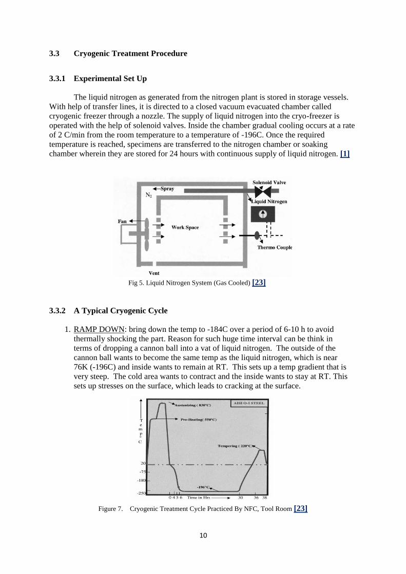
3.3 Cryogenic Treatment Procedure
3.3.1 Experimental Set Up
The liquid nitrogen as generated from the nitrogen plant is stored in storage vessels.
With help of transfer lines, it is directed to a closed vacuum evacuated chamber called
cryogenic freezer through a nozzle. The supply of liquid nitrogen into the cryo-freezer is
operated with the help of solenoid valves. Inside the chamber gradual cooling occurs at a rate
of 2 C/min from the room temperature to a temperature of -196C. Once the required
temperature is reached, specimens are transferred to the nitrogen chamber or soaking
chamber wherein they are stored for 24 hours with continuous supply of liquid nitrogen. [1]
Fig 5. Liquid Nitrogen System (Gas Cooled) [23]
3.3.2 A Typical Cryogenic Cycle
1. RAMP DOWN: bring down the temp to -184C over a period of 6-10 h to avoid
thermally shocking the part. Reason for such huge time interval can be think in
terms of dropping a cannon ball into a vat of liquid nitrogen. The outside of the
cannon ball wants to become the same temp as the liquid nitrogen, which is near
76K (-196C) and inside wants to remain at RT. This sets up a temp gradient that is
very steep. The cold area wants to contract and the inside wants to stay at RT. This
sets up stresses on the surface, which leads to cracking at the surface.
Figure 7. Cryogenic Treatment Cycle Practiced By NFC, Tool Room [23]
Page 11
11
2. SOAK: soak segment will hold the temperature at 123K (-150C) for 8-40 h. Crystal
structure of the metal changes at this temp at a slower rate. One of the changes is
the precipitation of fine carbides. In theory a perfect crystal lattice, structure is in
the lowest energy state. The total energy in the structure is higher with vacancies
and dislocations. By keeping the part at a low temperature for a long period of
time, we get some energy out of the lattice and make a more perfect and therefore
stronger crystal structure
3. RAMP UP: A typical ramp up segment brings the temperature back up to room
temperature in 8-20 h. The ramp up cycle is very important to the process.
Ramping up too fast can cause problems with the part being treated as happens by
dropping an ice cube into a glass of warm water, it cracks.
4. TEMPER RAMP UP: temper segment ramps the temp above the ambient to a
predetermined level over a period of time. Tempering is important with ferrous
metals. The cryogenic temperature will convert almost all retained austenite into
primary martensite, which is brittle. To reduce the brittleness it is tempered back
using the same tempering process as is used in a quench and temper cycle in heat
treatment. We ramp up the temp slowly to assure the temp gradients within the part
are kept low. Typically, tempering temp are from 422K (149C) on up to 866K
(593C), depending on the metal and required hardness
5. TEMPER HOLD: Holding the elevated temperature for a specific time. The temper
hold segment assures the entire part has had the benefit of the tempering
temperatures. A typical temper hold time is about 3 hours. This time depends on
the thickness and mass of the part. There may be more than one temper sequence
for a given part or metal. We have found that certain metals perform better if
tempered several times.
Page 12
12
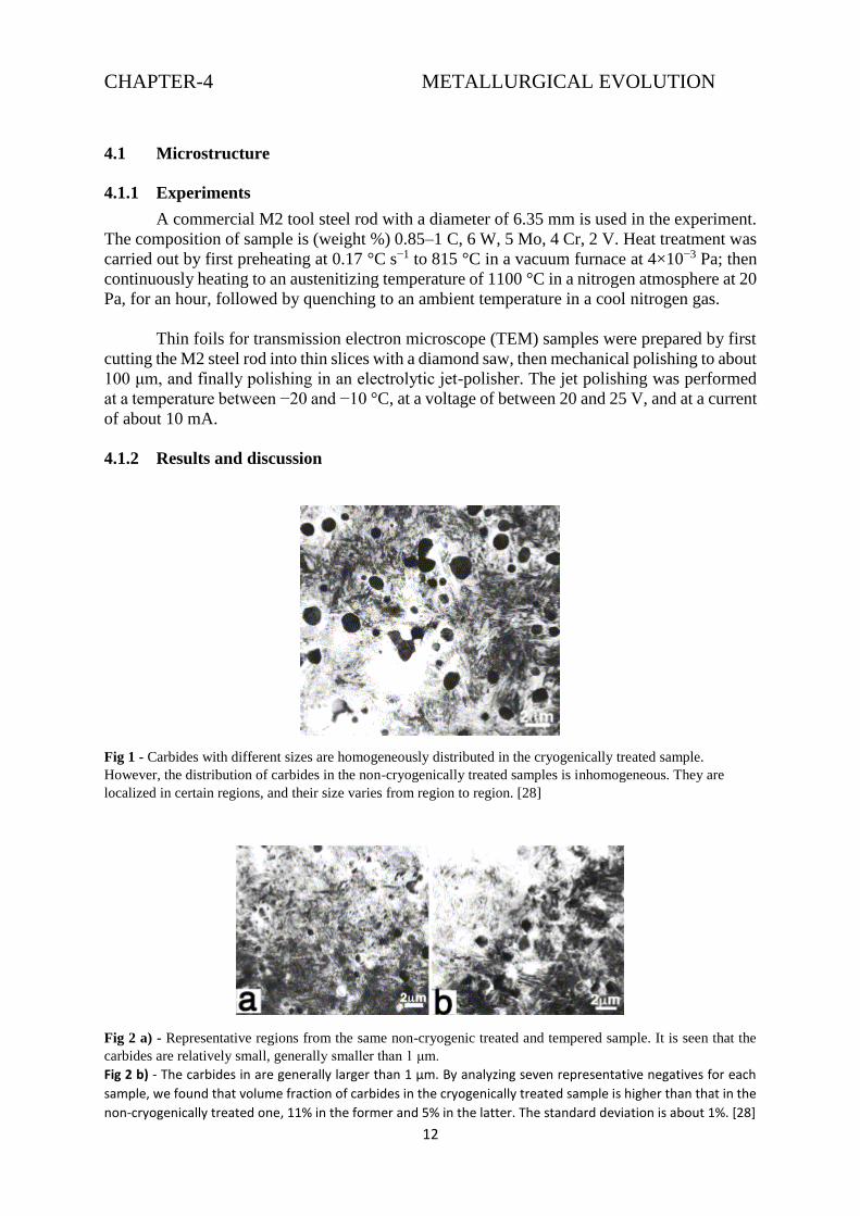
CHAPTER-4 METALLURGICAL EVOLUTION
4.1 Microstructure
4.1.1 Experiments
A commercial M2 tool steel rod with a diameter of 6.35 mm is used in the experiment.
The composition of sample is (weight %) 0.85–1 C, 6 W, 5 Mo, 4 Cr, 2 V. Heat treatment was
carried out by first preheating at 0.17 °C s−1 to 815 °C in a vacuum furnace at 4×10⁻³ Pa; then
continuously heating to an austenitizing temperature of 1100 °C in a nitrogen atmosphere at 20
Pa, for an hour, followed by quenching to an ambient temperature in a cool nitrogen gas.
Thin foils for transmission electron microscope (TEM) samples were prepared by first
cutting the M2 steel rod into thin slices with a diamond saw, then mechanical polishing to about
100 μm, and finally polishing in an electrolytic jet-polisher. The jet polishing was performed
at a temperature between −20 and −10 °C, at a voltage of between 20 and 25 V, and at a current
of about 10 mA.
4.1.2 Results and discussion
Fig 1 - Carbides with different sizes are homogeneously distributed in the cryogenically treated sample.
However, the distribution of carbides in the non-cryogenically treated samples is inhomogeneous. They are
localized in certain regions, and their size varies from region to region. [28]
Fig 2 a) - Representative regions from the same non-cryogenic treated and tempered sample. It is seen that the
carbides are relatively small, generally smaller than 1 μm.
Fig 2 b) - The carbides in are generally larger than 1 μm. By analyzing seven representative negatives for each
sample, we found that volume fraction of carbides in the cryogenically treated sample is higher than that in the
non-cryogenically treated one, 11% in the former and 5% in the latter. The standard deviation is about 1%. [28]
Page 13
13
Fig 3 - The microstructure and lattice parameter of the carbide were determined by selected area electron
diffraction patterns [28]
Fig 4 - And the composition of the carbide was obtained by energy dispersive X-ray spectrum [28]
Fig 5 - The particle size ranges from 0.3 to 2 μm, and the particle size distributions in the cryogenic treated and
non-cryogenic treated samples are very similar. However, the population, volume fraction and distribution of
carbides in the two samples are different. The carbides are distributed more homogeneously in the cryogenic
treated sample than in the non-cryogenically treated one. [28]
Page 14
14
4.2. Crystallographic textures
4.2.1 Introduction
The texture evolution of metals is an interesting way in forming operations because it
largely dictates the mechanical anisotropy of the final products. As texture induces anisotropic
plastic flow, a good numerical description of forming operations requires establishing a
relationship between texture and constitutive laws, especially when free surfaces exist.
The integration of crystallographic textures into the modeling of metal forming requires
to perform at least two length scale transitions. The first one relates the process boundary
conditions to the local thermal and mechanical conditions of the material, supposed to be
homogeneous. A second length scale transition then partitions the strain and stress fields among
the various grains or crystals representing the microstructure of the material (at the integration
point), according to linking assumptions.
4.2.2. Polycrystalline plasticity background:
4.2.2.1. Single crystal constitutive equation:
The grain constitutive law is derived from the slip system constitutive law and from the single
crystal elastic constants [24]. At high temperatures or under large strains, rigid–visco plastic
laws are usually high, i.e. elastic deformations are neglected with respect to plastic
deformation. A power law is then often chosen to relate the applied resolved shear stress on
the slip or twinning system (s). Each deformation (slip or twinning) system is characterized by
a unit vector n (s), normal to the slip or twinning plane, and a unit vector b (s), the Burgers vector
in the case of slip and the twin shear direction in the case of twinning.
4.2.2.2. Linking assumption
An accurate description of the polycrystalline nature of the material requires a minimum of a
few hundred representative grains. The polycrystalline models used to partition stress and strain
among the crystals differ among each other by their linking assumptions. The polycrystal
stress is computed as the volumetric average of the individual crystal stresses.
Taylor-type linking assumptions of homogeneous deformations through the aggregate are
pertinent for cubic metals, but no longer describe accurately the behavior of lower symmetry
alloys [25]. They usually describe viscoplastic or elastic–viscoplastic behaviors; other
formulations based on an elastic–plastic behavior indeed suffer from discontinuous
relationships between stress and strain.
Page 15
15
CHAPTER-5 EXPERIMENTAL DETAILS
5.1 Effects of Cryogenic Treatment:
5.1.1 Microstructural evaluation:
This treatment results in significant amount of retained austenite which has some damaging
effects on mechanical properties of tool steels such as machinability, wear, hardness and most
important of all on dimensional stability of tool steels. The latter could be a very significant
factor in the case of using the tool steels for die material applications. Thus different treatment
cycles were applied on the samples to study the effects of low temperature treatments on tool
steel. This was done by cooling the samples at temperatures well below the M f temperature of
the tool steel and holding the samples in this temperature range.
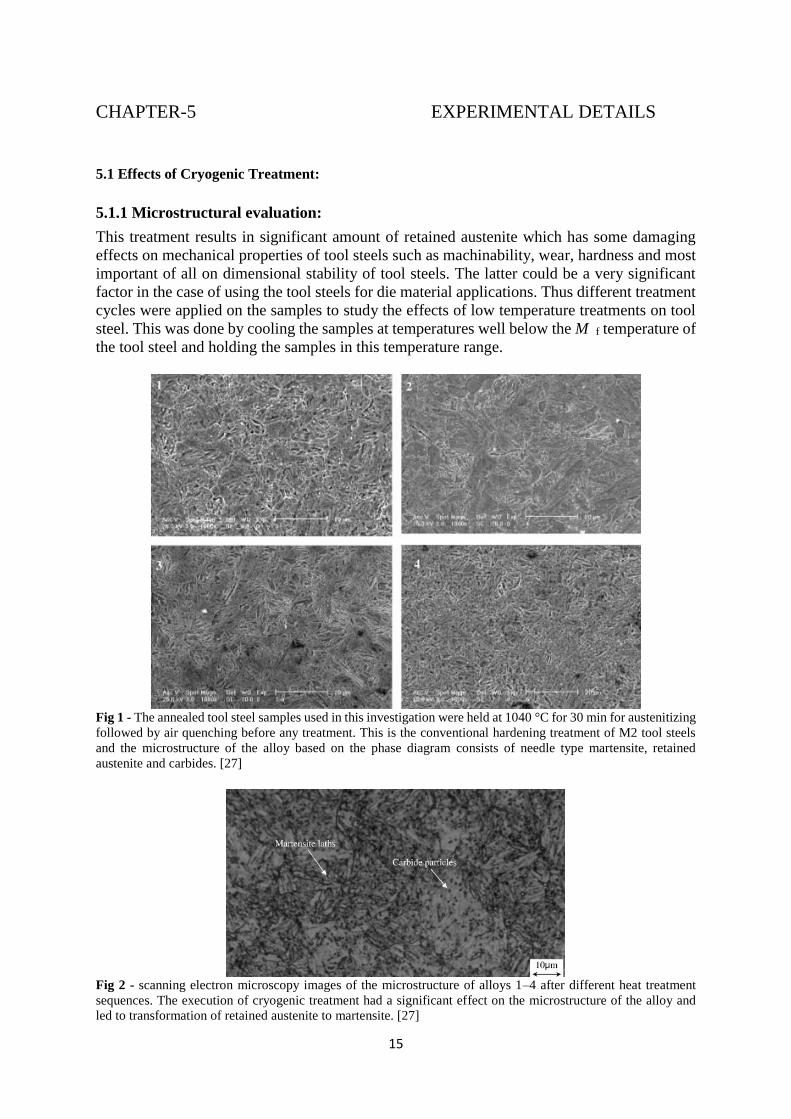
Fig 1 - The annealed tool steel samples used in this investigation were held at 1040 °C for 30 min for austenitizing
followed by air quenching before any treatment. This is the conventional hardening treatment of M2 tool steels
and the microstructure of the alloy based on the phase diagram consists of needle type martensite, retained
austenite and carbides. [27]
Fig 2 - scanning electron microscopy images of the microstructure of alloys 1–4 after different heat treatment
sequences. The execution of cryogenic treatment had a significant effect on the microstructure of the alloy and
led to transformation of retained austenite to martensite. [27]
Page 16
16
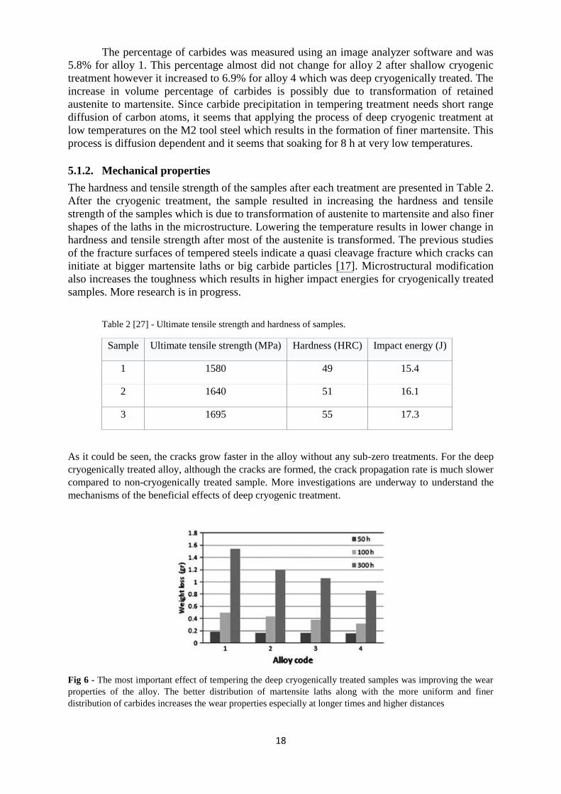
Fig 3 - As the cryogenic temperature is lowered, more austenite is transformed to martensite. X-ray pattern of the
alloy after conventional treatment is shown in the figure. [27]
For the calculations, peaks (2 0 0) and (2 1 1) of martensite and (3 1 1) and (2 2 0) of austenite
were employed. The lower angle peaks (1 1 0) of martensite and (1 1 1) of austenite were neglected
because they appear very close to each other which could introduce errors in the evaluation of their
integrated intensities[26]. The measurement of percentage retained austenite in the microstructure
(Table 1) also verifies the transformation of retained austenite to martensite. Furthermore, the
transformation of austenite to martensite results in the volume increase which causes tensile stress on
austenite.
Table 1. [27] Retained austenite volume content after different treatment cycles.
Sample Retained austenite percent (%)
1 8.1
2 7.4
3 4.5
4 3.8
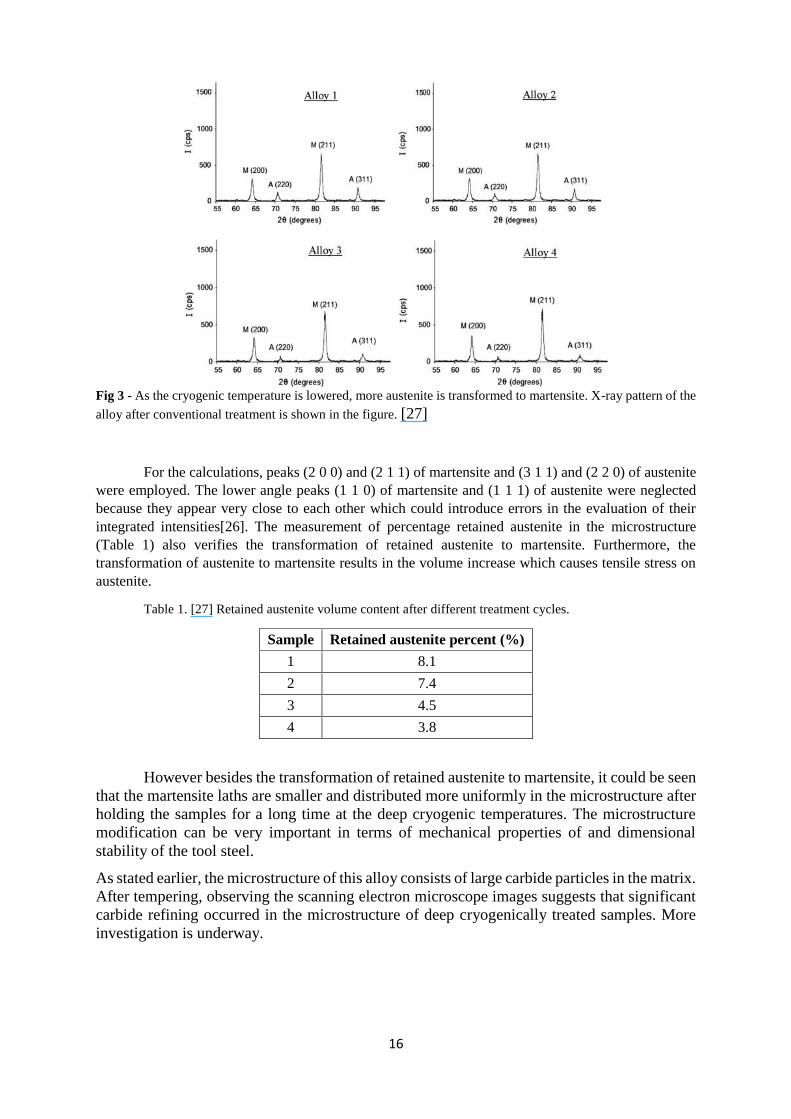
However besides the transformation of retained austenite to martensite, it could be seen
that the martensite laths are smaller and distributed more uniformly in the microstructure after
holding the samples for a long time at the deep cryogenic temperatures. The microstructure
modification can be very important in terms of mechanical properties of and dimensional
stability of the tool steel.
As stated earlier, the microstructure of this alloy consists of large carbide particles in the matrix.
After tempering, observing the scanning electron microscope images suggests that significant
carbide refining occurred in the microstructure of deep cryogenically treated samples. More
investigation is underway.
Page 17
17
. Fig 4 - Further examination of the microstructure indicates that there are mainly two different kinds of carbides,
chromium (black) and molybdenum (white) carbides is shown. The cryogenic treatment at a very low temperature
and holding the samples for a long time result in precipitation of very fine and more uniform distribution of carbide
particles in the microstructure after tempering. [27]
Fig 5 - The chromium carbides are the dominant carbides in the microstructure. The energy dispersive X-ray
analysis of both kinds of carbides is shown. [27]
Page 18
18
The percentage of carbides was measured using an image analyzer software and was
5.8% for alloy 1. This percentage almost did not change for alloy 2 after shallow cryogenic
treatment however it increased to 6.9% for alloy 4 which was deep cryogenically treated. The
increase in volume percentage of carbides is possibly due to transformation of retained
austenite to martensite. Since carbide precipitation in tempering treatment needs short range
diffusion of carbon atoms, it seems that applying the process of deep cryogenic treatment at
low temperatures on the M2 tool steel which results in the formation of finer martensite. This
process is diffusion dependent and it seems that soaking for 8 h at very low temperatures.
5.1.2. Mechanical properties
The hardness and tensile strength of the samples after each treatment are presented in Table 2.
After the cryogenic treatment, the sample resulted in increasing the hardness and tensile
strength of the samples which is due to transformation of austenite to martensite and also finer
shapes of the laths in the microstructure. Lowering the temperature results in lower change in
hardness and tensile strength after most of the austenite is transformed. The previous studies
of the fracture surfaces of tempered steels indicate a quasi cleavage fracture which cracks can
initiate at bigger martensite laths or big carbide particles [17]. Microstructural modification
also increases the toughness which results in higher impact energies for cryogenically treated
samples. More research is in progress.
Table 2 [27] - Ultimate tensile strength and hardness of samples.
Sample Ultimate tensile strength (MPa) Hardness (HRC) Impact energy (J)
1 1580 49 15.4
2 1640 51 16.1
3 1695 55 17.3
As it could be seen, the cracks grow faster in the alloy without any sub-zero treatments. For the deep
cryogenically treated alloy, although the cracks are formed, the crack propagation rate is much slower
compared to non-cryogenically treated sample. More investigations are underway to understand the
mechanisms of the beneficial effects of deep cryogenic treatment.
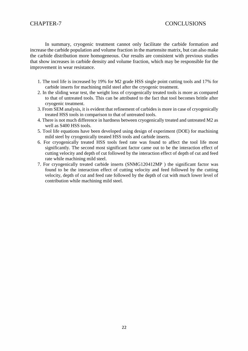
Fig 6 - The most important effect of tempering the deep cryogenically treated samples was improving the wear
properties of the alloy. The better distribution of martensite laths along with the more uniform and finer
distribution of carbides increases the wear properties especially at longer times and higher distances
Page 19
19
Fig 7 - The improvement of wear properties is more noticeable in the samples worn after 30 h compared with
shorter times, which is probably due to rapid propagation of initial cracks that form at earlier stages of wear. It
seems that the smaller and more uniform distribution of carbides plays an important role in inhibiting the growth
formation of cracks due to strengthening of the microstructure. This behavior can also be related to the retained
austenite present in the structure and its transformation to martensite under cold processing conditions as stated
earlier. Scanning electron microscopy images of the worn surfaces are shown. [27]
5.2 Laboratory Test:
5.2.1. Flank wear tests Tool wear is always used as a tool life criterion because it is easy to determine. Various types of tool
wear are shown below.
The amount of flank wear is often used as a criterion because it is the flank wear that influences work
material surface roughness and accuracy. A standard tool life is the time to develop a flank wear land
of recommended size based on the material and operation as depicted in the table.
Wear (in) Tool Material Remarks
0.030 (0.76 mm) Carbide Roughing passes
0.010-0.015 (0.25-0.38 mm) Carbide Finishing passes
0.060 or total destruction(1.25 mm) H.S.S. Roughing passes
0.010-0.015 (0.25-0.38 mm) H.S.S. Finishing passes
0.010-0.015 (0.25-0.38 mm) Cemented oxides Roughing
Page 20
20
Fig: Typical stages of tool wear as well as illustrates the method to evaluate tool life from flank wear graphically.
In the present work, the tool samples were subjected to turning operation in a high speed lathe with a maximum
spindle speed of 1200 RPM. As soon as lathe was started, stop watch was switched on to note down the machining
time. At the end of each run, flank wear was measured in a tool maker’s microscope at every 2 minutes interval.
The total machining time before reaching a minimum of 0.3 mm flank wear was considered to be the tool life of
the sample.
5.2.2. Sliding wear tests
The materials considered for this were the cryogenically treated as well as untreated S400
and M2 grade HSS samples with dimensions 20 x 16 x 16 mm. The test was conducted on a
machine called disc and pinion. The sample was mounted perpendicularly on a stationary vice
such that it’s one of the face is forced to press against the abrasive that is fixed on the revolving
disc. Hence it is the abrasive paper that tends to wear the surface of the samples. When the disc
rotates for a particular period of time the sample can be loaded at the top to press against the
disc with the help of a lever mechanism.
The speed of revolution can also be varied and thus the test can be conducted with the
following parameters-
(1) Load (2) Speed (3) Time In the present experimental work, speed and time wear kept constant while the load was varied from 0
to 1.2 kg. Parameters that remained constant through out all the experiments are given in table (3).
Page 21
21
RPM 300
Time 1hr
Type of abrasive paper Emery Table 5.3. Parameters taken constant in sliding wear test
For each of the sample, test was conducted for 5 times and the average of all the samples was
taken as the observed values in each case. Once the parameter is set and work piece is mounted,
the test is carried on for the desired time. The wear track so formed on the rotating disc is a
circle. After each test only the mass loss of the specimen was considered as the wear.
The wear rate of each sample was calculated from the weight loss, the amount of wear is
determined by weighing the specimen before and after the test using precession electronic
weighing machine with accuracy 0.0001 gm. Since the mass loss is measured it is converted to
volume loss using the density of the specimen. A comparison has been made to identify effects
of cryogenic treatment on wear improvement on S400 and M2 grade HSS samples. The test
was conducted for 5 times for each of the samples.
5.2.3. Hardness test Rockwell hardness testing is a general method for measuring the bulk hardness of metallic and
polymer materials. Although hardness testing does not give a direct measurement of any
performance properties, hardness correlates with strength, wear resistance, and other
properties. Hardness testing is widely used for material evaluation due to its simplicity and low
cost relative to direct measurement of many properties. This method consists of indenting the
test material with a diamond cone or hardened steel ball indenter. The indenter is forced into
the test material under a preliminary minor load F0 (Fig A) usually 10 kgf. When equilibrium
has been reached, an indicating device, which follows the movements of the indenter and so
responds to changes in depth of penetration of the indenter, is set to a datum position. While
the preliminary minor load is still applied an additional major load is applied with resulting
increase in penetration (Fig B). When equilibrium has again been reach, additional major load
is removed but the preliminary minor load is still maintained. Removal of the additional major
load allows a partial recovery, so reducing the depth of penetration (Fig C). The permanent
increase in depth of penetration, resulting from the application and removal of the additional
major load is used to calculate the Rockwell hardness number.
Fig.Rockwell Principle
In the present experimental work Rockwell Hardness was measured on cryogenically treated and untreated S400
and M2 grade HSS samples with a minimum of four indentations in each. The average of these measurements
was considered for comparison.
Page 22
22
CHAPTER-7 CONCLUSIONS
In summary, cryogenic treatment cannot only facilitate the carbide formation and
increase the carbide population and volume fraction in the martensite matrix, but can also make
the carbide distribution more homogeneous. Our results are consistent with previous studies
that show increases in carbide density and volume fraction, which may be responsible for the
improvement in wear resistance.
1. The tool life is increased by 19% for M2 grade HSS single point cutting tools and 17% for
carbide inserts for machining mild steel after the cryogenic treatment.
2. In the sliding wear test, the weight loss of cryogenically treated tools is more as compared
to that of untreated tools. This can be attributed to the fact that tool becomes brittle after
cryogenic treatment.
3. From SEM analysis, it is evident that refinement of carbides is more in case of cryogenically
treated HSS tools in comparison to that of untreated tools.
4. There is not much difference in hardness between cryogenically treated and untreated M2 as
well as S400 HSS tools.
5. Tool life equations have been developed using design of experiment (DOE) for machining
mild steel by cryogenically treated HSS tools and carbide inserts.
6. For cryogenically treated HSS tools feed rate was found to affect the tool life most
significantly. The second most significant factor came out to be the interaction effect of
cutting velocity and depth of cut followed by the interaction effect of depth of cut and feed
rate while machining mild steel.
7. For cryogenically treated carbide inserts (SNMG120412MP ) the significant factor was
found to be the interaction effect of cutting velocity and feed followed by the cutting
velocity, depth of cut and feed rate followed by the depth of cut with much lower level of
contribution while machining mild steel.
Page 23
23
REFERENCES
[1] Amrita Priyadarshini and KP Maity,”A Study of the Effect of Cryogenic Treatment
on the Performance of High Speed Steel Tools and Carbide Inserts” Mtech Thesis,
NIT Rourkela (2007): pp. 18
[2] Barron, R.F.; Mulharn, C.R. “Cryogenic Treatment of AISI T8 and C1045 Steels”
Cryogenic Engineering Conference, Madison, WI, August 21–24, 1979; Plenum
Press: New York, 1980.
[3] (B) Vaccari J.A., “Deep freeze improves products”. Amer. Machinist Automated
Manuf. March (1986)
[4] Mahmudi, Ghasemi ,Faradji, “Effect of cryogenic treatments on the mechanical
properties and wear behavior of high-speed steel M2”, Heat Treat. Met. Volume
No.27, (2000): pp. 69–72
[5] (B) Zamborsky D.S.,” Control of distribution in Tool steels”, The Heat treating
Source book (1986): pp. 73-79
[6] Dong, Lin ,Xiao, “Deep cryogenic treatment of high-speed steel and its mechanism”
Heat Treatment of Metals Volume .No. 3, (1998): pp. 55–59
[7] (B) Dong, Lin, Xiao. Heat Treatment of Metals (1998) pp. 55
[8] (B) Vaccari J.A., “Deep freeze improves products”. Amer. Machinist Automated
Manuf. March (1986)
[9] (B) W.E. Bryson. Cryogenics, Cincinnati: Hanser Gardner Publications (1999)
[10] Simranpreet Singh Gill, Harpreet Singh, Rupinder Singh, Jagdev Singh
“Cryoprocessing of cutting tool materials”, The International Journal of Advanced
Manufacturing Technology April 2010, Volume 48, Issue 1-4, pp 175-192
[11] A. Molinari, M. Pellizzari, S. Gialanella “Effect of deep cryogenic treatment on the
mechanical properties of tool steels” Journal of Materials Processing Technology
Volume 118, Issues 1–3, 3 December 2001, Pages 350–355
[12] Dr. R. G. Tated, Dr. S. R. Kajale, Dr. Kumar Iyer, “Improvement in tool life of
cutting tool by application of deep cryogenic treatment” 7th International tooling
conference held at Politecnico di Torino, Italy 2-5 May (2006): pp. 135-141
[13] National Institute of Standards and Technology, Boulder, Colorado. Published in: The
MacMillan Encyclopedia Of Chemistry, New York (2002)
[14] (B) Nordquist, W.N. Low temperature treatment of metals. Tooling and Production
Magazine (1953): Ch.7 pp. 72–100
[15] (B) Mazur, J. Investigation of austenite and martensite subjected to very low
temperatures. Cryogenics (1964): Ch.4 pp. 36
[16] (B) Baldissera, P.; Delprete, C. Effects of deep cryogenic treatment on static
mechanical properties of 18NiCrMo5 carburized steel. Materials and Design (2009):
Ch.30 pp. 1435–1440
Page 24
24
[17] Barron, R.F. Cryogenic treatment of metals to improve wear resistance. Elsevier-
Cryogenics Volume 22, Issue 8, August 1982, Pages 409–413
[18] Smolnikov, Kossovich, “Cold Treatment of Cutting Tools” Metal Science and Heat
Treatment October 1980, Volume 22, Issue 10, pp 704-705
[19] Amrita Priyadarshini and KP Maity,”A Study of the Effect of Cryogenic Treatment
on the Performance of High Speed Steel Tools and Carbide Inserts” Mtech Thesis NIT
Rourkela (2007): 14-15
[20] Melvin R. Meyerson and Samuel J. Rosenberg,” A Study of the Final Stages of the
Austenite to Martensite Transformation in SAE 1050 Steel” Journal of Research of
the National Bureau of Standards Vol. 55 No.3, (1955): pp. 178-179
[21] (B) Shackelford, 1996
[22] (B) Timmerhaus K.D, Reed R.P “Cryogenic Engineering” Springer: New York, USA
(2007): pp. 3–27
[23] A D Wale, Prof. V D Wakchaure “Effect of Cryogenic Treatment on Mechanical
Properties of Cold Work Tool Steels” International Journal of Modern Engineering
Research Vol.3, Issue.1, Jan-Feb. 2013 pp-149-154
[24] R.J. Asaro, A. Needleman “Texture development and strain hardening in rate-
dependent polycrystals” ELSEVIER- Acta Metallurgica vol-33 (1985), pp. 923–953
[25] Y. Chastel, P. Dawson, H.-R. Wenk, K. Bennett “Anisotropic convection with
implications for the upper mantle” Journal of Geophysical Research: Solid Earth
(1978–2012) Volume 98, Issue B10, pages 17757–17771, 10 October 1993
[26] (B) P.R. Dawson, Computational crystal plasticity, 37 (2000), pp. 115–130
[27] Mahdi Koneshlou, Kaveh Meshinchi Asl, Farzad Khomamizadeh “Effect of
cryogenic treatment on microstructure, mechanical and wear behaviors of AISI M2
hot work tool steel” Elsevier- Cryogenics Volume 51, Issue 1, January 2011, Pages
55–61
[28] R.E. LogéY.B. Chastel, “Coupling the thermal and mechanical fields to metallurgical
evolutions within a finite element description of a forming process” Computer
Methods in Applied Mechanics and Engineering Volume 195, Issues 48–49, 1
October 2006, Pages 6843–6857
Page 25
25
Declaration
In the preparation of this `B.Tech. Seminar Report’ the following members of the team
have contributed to different parts of the report, nevertheless all of us have gone through the
whole report carefully.
Name & Roll No. Contributed mainly
to the following
chapters / sections
Contents
(titles / subtitles only)
Tushar Mamodia
Roll no. 11D110015
Abstract
Chapter-1
Chapter-2
Chapter-3
Conclusions
Tool Steel and High Speed Steel
Cryogenics
Cryogenic Treatment
Rahul Maghanti
Roll no. 110110061
Chapter-4
Chapter-5
Metallurgical Evolution
Experimental Details
Further, we are aware that if the report write-up does not conform to the standard format
(given on the MEMS website), it (report) is likely to be rejected.
The oral presentation of different parts of the seminar shall be made by the respective
student(s).
Signatures:
Date: 21/03/2014
View publication statsView publication stats