Cryogenic Tribology in High-Speed Bearings andShaft Seals of Rocket Turbopumps
Masataka Nosaka and Takahisa Kato
Additional information is available at the end of the chapter
http://dx.doi.org/10.5772/55733
1. Introduction
In recent years, as a rule, improvement of the reliability of liquid propellant rockets becomesan international technical problem for built-up of safe space transport systems. The highperformance, liquid propellant rocket engines require high-pressured turbopumps to deliverextremely low temperature propellants of liquid oxygen (LO2, boiling point 90 K) and liquidhydrogen (LH2, boiling point 20 K) to a combustion chamber in engine [1]. In LO2/LH2
turbopumps, cryogenic high-speed bearings and rotating-shaft seals are very important partsto sustain high reliability of the high-rotating-shaft systems. The turbopump bearings aredirectly equipped in cryogenic propellants in pump side [2]. The shaft seal systems are alsoset up between the cryogenic pumps and the hot turbines to restrain the leakage of cryogenicpropellants and hot turbine gas [3].
These bearing and shaft seals have to operate under poor lubricating conditions due toextremely small viscosity at cryogenic temperatures. Furthermore, the turbopump bearingsand shaft seals have to overcome a severe high-speed operation that has several critical speedsdemonstrating self-induced severe vibration of the rotating shaft. In order to develop turbo‐pump bearings and shaft seals, many inexperienced technical and tribological problems mustbe solved for extremely low temperature and high speed of operational conditions. Suchcryogenic tribological technology has been playing a key role in cryogenic turbopumps toachieve high reliability.
This chapter presents a topical review of cryogenic tribological studies (for about 30 years inJapan) on the research and development of the cryogenic high-speed bearings and shaft sealsof rocket turbopumps [4, 5]. The high-speed bearings and shaft seals were continually studiedfor the LE-5 engine used in the Japanese H-I rocket (developed in 1986) and the LE-7 engineused in the H-II rocket (developed in 1994). The bearings and shaft seals used in LO2/LH2
turbopumps of the LE-5 and LE-7 had a rotational speed level of 50,000 rpm and had beenstudied and developed from the mid-1970 to the mid-1990. Specially, the all-steel bearings(made of AISI 440C) of the LH2 turbopump of the LE-7 demonstrated high performance withhigh reliability at high-speed level at 2 million DN (40 mm x 50,000 rpm). The shaft seal systemsin the LE-5/LE-7 turbopumps that used a mechanical seal, a floating ring seal (annular seal)and a segmented seal are also reviewed.
Furthermore, for future space transport systems to reduce launch cost and to increase effi‐ciency, advanced rocket engines which are characterized by high durability (long life) and highperformance (light weight) are required in recent years. Advanced bearing and shaft seal thathave high durability, i.e., a long life of 7.5 hours for the turbopump bearings used in reusablespace shuttle main engine (the SSME). Its required life is 15 times longer than that (30 minutes)of the turbopump bearings used in the LE-7. At the first time, the SSME turbopump bearingsexperienced a serious wear problem in LO2 due to poor self-lubrication of the retainer [6]. Inorder to extend bearing life, the hybrid ceramic bearing with Si3N4 balls was used to reduceserious wear in the conventional all-steel bearing. A new type of the retainer having PTFE/bronze-powder insert was also developed to obtain sufficient self-lubrication of the hybridceramic bearing. Consequently, the improvement of the SSME turbopump bearings needed along time of about 20 years [7].
Today, ultra-high speed level above 100,000 rpm is required to make a small and lightturbopump for advanced second-stage engine. These advanced research and development areactively underway. In Japan, a new type of hybrid ceramic bearing having Si3N4 balls with asingle guided retainer demonstrated excellent performance at an ultra-high speed of 120,000rpm (3 million DN) in LH2 and recorded the world’s top speed (in 2001) [8]. The result of thisbearing was applied to the LH2 turbopump (rotational speed, 90,000 rpm) of the RL60demonstrator engine (in 2003). The RL60 demonstrator engine was developed in the USA withinternational collaboration (USA, Japan, Russia and Sweden) and the LH2 turbopump wasdeveloped by a Japanese company [9]. In Europe, for the VINCI engine under development,high-DN hybrid ceramic bearing was tested in LH2 at a speed of 70,000 rpm (2.8 million DN)and continuous studies on a high-DN bearing was conducted at DN up to 3.3 million (120,000rpm) in LH2 (in 2005) [10]. Furthermore, in Russia, for the developed RD0146 engine, itsrotational speed of the main LH2 turbopump was 123,000 rpm (3.08 million DN), but detail ofits bearing was unknown (in 2003) [11].
This chapter also reviews advanced bearings and shaft seals which were studied from themid-1990 to the mid-2000 after the development of turbopump bearings and shaft seals ofthe LE-7 [4,5]. It is typical that a long-life bearing with single-guided retainer demonstrat‐ed a long operation for 12 hours under 50,000 rpm. A hybrid ceramic bearing having single-guided retainer and Si3N4 balls was able to demonstrate ultra-high-speed performance atspeeds up to 120,000 rpm and show excellent performance under 3 million DN. An annularseal made of an Ag plated steel ring also presented two-phase seal performance at speedsup to 120,000 rpm.
These historical reviews are intended to help the technical succession to next young generationwho challenges research and development of the future space transportation system. These
Tribology - Fundamentals and Advancements110
reviews are based on previous studies carried out by Japan Aerospace Exploration Agency(JAXA) at Kakuda Space Center. All materials used in this chapter have been published bypapers.
Figure 1. Typical tribo-components and solid lubricants used in turbopumps
2. Bearings and shaft seals of turbopumps
2.1. Turbopumps and tribo–components
The LO2/LH2 turbopumps as well as the tribo-components, such as high-speed bearings androtating shaft-seals, were studied and developed to use in the LE-5 and LE-7. In reference tothe structure of the LH2 turbopump of the LE-7, the tribo-components and solid lubricantsused in the LE-5 and LE-7 turbopumps are typically indicated in Fig. 1 [4]. In addition, maindesign parameters of the turbopumps and DN values of bearings for the LE-5 and LE-7 arelisted in Table 1 [5]. Here, the DN value that represents high-speed level of bearing is definedas the product of the inner-race bore diameter D (in mm) and the pump rotational speed N (inrpm). The rotor speed is typically restricted by the DN limits of the bearing.
Cryogenic Tribology in High–Speed Bearings and Shaft Seals of Rocket Turbopumpshttp://dx.doi.org/10.5772/55733
111
Engine (thrust)
Rocket
Engine cycle
LE-5 (10 tons)
Second stage of H-1
Gas-generator cycle
LE-7 (86 tons)
First stage of H-2
Staged-combustion cycle
Turbopump LO2 LH2 LO2 LH2
Pump pressure [MPa]
Pump flow rate [kg/s]
Shaft rotational speed [rpm]
Bearing DN [mm x rpm]
Turbine pressure [MPa]
Turbine temperature [K]
Turbine gas flow rate [kg/s]
Shaft power [kW]
Weight [kg]
5.2
20
16,500
49.5 x 10⁴
0.48
690
0.39
130
23
5.5
3.6
50,000
125 x 104
2.4
840
0.42
490
25
17.4 (25.8)*
212 (46)*
18,000
81 x 104
19.1
810
14.9
4,700
160
27.0
36
42,000
168 x 104
20.6
830
33.6
19,700
200
For pre-burner in bracket; ( )*
Table 1. Design parameters of turbopumps and DN values of bearings for LE-5 and LE-7
a. LE-5 turbopumps
For the upper stage of the H-I rocket, the LE-5 had a gas-generator cycle with 10-ton thrustand its chamber pressure of 3.4 MPa was relatively low. Its engine cycle is not able to achievea high engine performance due to an open cycle. For the LH2 turbopump of the LE-5, the pumpdischarge pressure was relatively low at 5.5 MPa and the discharge flow rate was 51 liters/s.The turbine pressure was 2.4 MPa. The paired bearings of 25-mm bore operated at a speed of50,000 rpm (1.25 million DN) and sustained the shaft power of 490 kW [12].
For the LO2 turbopumps, the discharge pressure was 5.2 MPa and the discharge flow rate was18 liters/s. The turbine pressure was 0.48 MPa. The paired bearings of 30-mm bore operatedat a speed of 16,500 rpm and sustained the shaft power of 130 kW. Basic design and technologyof the cryogenic tribo-components used in the small turbopumps was experimentally estab‐lished under the development of the LE-5.
b. LE-7 turbopumps
For next technical challenge in the first stage engine of the H-II rocket, the LE-7 had a staged-combustion cycle (similar to that of the SSME) with 100-ton thrust and a high chamber pressureof 13 MPa. Its engine cycle can obtain high performance due to a closed engine cycle. For thehigh-pressure, large LH2 turbopump of the LE-7, the pump discharge pressure was increasedto 27 MPa, and the discharge LH2 flow rate was 510 liters/s. The turbine pressure was relativelyhigh at 20.6 MPa. The paired bearings of 35-mm bore were at the inducer side, and the pairedbearings of 40-mm bore were at the turbine side. These bearings operated at a speed of 42,000rpm (1.68 million DN) and sustained the shaft power of 19,700 kW [13,14].
For the LO2 turbopumps, the discharge pressure was 18 MPa for the main pump and 26 MPafor the preburner pump, respectively. The total discharge LO2 flow rate was 240 liters/s. The
Tribology - Fundamentals and Advancements112
turbine pressure was 19.1 MPa. The paired bearings of 32-mm bore were located at the inducerside and the paired bearings of 45-mm bore were at the turbine side. These bearings operatedat a speed of 18,000 rpm and sustained the shaft power of 4,700 kW [14,15].
c. Tribo-components in turbopumps
As shown in Fig. 1, it is important to prohibit severe friction and wear in cryogenicenvironment that various solid lubricants are applied to the frictional parts in static anddynamic tribo-components. Since the turbopums are operated under large power condi‐tions connecting with high fluid and mechanical vibration, it must pay attention that manycomponents in contact are sure to generate relative motion and resulted in severe adhe‐sive conditions. It needs proper lubrication to avoid severe frictional adhesion of assem‐bled parts used in cryogenic environment.
The rotor of turbopump is directly supported by two sets of self-lubricated ball bearings incryogenic pump fluid. The shaft seal of turbopump is installed between the cryogenic pumpand the hot gas turbine. The shaft seal system must seal the cryogenic propellants and thecombustion gases (steam with rich hydrogen gas) safely and securely. High-speed compo‐nents, such as bearings, shaft seals, Labyrinth seals, wear rings and balance pistons, used theproper solid lubricants to protect them from severe friction and wear in the reduction (LH2)or oxidation (LO2) environment of the cryogenic propellants. It is noted that these high-speedtribo-components are important life-controlling parts in engines [4].
2.2. Self–lubricating bearings
2.2.1. Self–lubrication of retainer
The turbopump bearings are all-steel (AISI 440C) bearings that are self-lubricated by the PTFEtransfer film as a lubricant from the reinforced PTFE (polytetra fluoroethylene) retainer. AISI440C is martensitic stainless steel (with 16-18%Cr) and is one of the most widely used bearingmaterials in space systems because such high-Cr steel has a high corrosion resistance due to asuperficial surface layer of Cr2O3. The resin PTFE retainer is reinforced with glass fiber, carbonfiber and laminated glass cloth to reduce wear as well as thermal contraction of the retainer.Although PTFE material has poor mechanical strength at room temperature, it has the bestlubricant for use at cryogenic temperature because its mechanical tensile stress drasticallyincreases and reaches to 80 MPa in LO2 and 130 MPa in LH2, respectively. In order to reducewear of the PTFE composite retainer with poor thermal conductivity, sufficient cooling of theretainer is need to eliminate heat generation detrimental to successful bearing operation athigh speeds [16].
Since LH2 and LO2 are particularly poor as lubricants because of their low viscosity underconditions of reduction or oxidation, hydrodynamic fluid lubrication is less effective. It is notedthat the cryogenic pump fluids works to remove severe frictional heat and to prevent thetemperature rise in the bearing. At low temperatures, the PTFE transfer film as a lubricant iskept to be hard and to sustain the bearing load, so that softening and rupturing of the transferfilm due to a rise in temperature have to be eliminated. Under poor cooling conditions, it
Cryogenic Tribology in High–Speed Bearings and Shaft Seals of Rocket Turbopumpshttp://dx.doi.org/10.5772/55733
113
appears that the blackened transfer film due to thermal decomposition of PTFE should occurat a high temperature above about 500 K, and the degraded transfer film was not able to sustainthe bearing load. Therefore, sufficient cooling by cryogenic fluids, as well as reduction offrictional heat generation, is very important to produce a durable lubricant film transferredfrom the retainer even in cryogenic fluid [14].
2.2.2. High–speed and load conditions of bearing
For the turbopump bearings, angular-contact bearings are usually used in pairs in duplexmounts (back to back). For example, Table 2 shows main design parameters and internal loadconditions for the bearings used in the LH2 turbopumps of the LE-5 and LE-7 [17,18]. In thistable, the SVmax value (=Smax x Vmax/2) that represents the maximum product of stress timesspinning velocity in the contact ellipse zone at the inner race are shown. Here, Smax is themaximum contact stress and Vmax is the maximum spinning velocity. The SVmax value is animportant factor related to lubrication and wear at the inner race with ball spinning [13,19].High SVmax value leads to high frictional heating and to wear of the PTFE transfer film dueto spin wear. Under poor cooling condition and large tilted misalignment, the turbopumpbearings have an initial contact angel of 15-25 deg. with a large radial clearance to prevent aloss of operating clearance from bearing seizer. As mention later, high-speed bearing has theouter-race ball control that produces high ball spinning at the inner race. In order to reducethe stress level within the spinning contact zone, race curvatures were controlled to be 0.54-0.56for inner race and 0.52 for the outer race, respectively. The inner race has a counter-bore typeto gain sufficient cooling within the bearing.
As the centrifugal force developed on the balls increases at high speeds, the operational contactangle at the inner and the outer races are changed to be different each other. The operationalcontact angle at the inner race increases rather than the initial contact angle and decreases tonear zero at the outer race. This divergence of contact angles tends to increase ball spinning inaddition to rolling at the inner race. Its spin velocity due to ball spinning becomes high andresults in an occurrence of frictional heat generation. To contrast, rolling contact at the outerrace generates differential slip due to curvature of contact ellipse [20].
Under the outer-race control connected with ball spinning at the inner race, heat generationdue to ball spin is significantly higher than that of differentia slip, so that sufficient cooling isnecessary at the inner race side. Furthermore, sliding velocity of the rolling balls in contactwith the outer guide land and the ball pocket is high and resulted in a generation of frictionalheating of the retainer. The bearings were effectively cooled by the pump cryogenic fluidscirculating in the turbopumps. For example, Fig. 2 shows sliding frictional conditions of theinner and outer raceways for the 25-mm-bore bearing that is at a speed of 50,000 rpm under athrust load of 980 N [16]. This bearing was used in the LH2 turbopump bearing for the LE-5.In this figure, the distribution of the contact stress, the spinning velocity and the SV value withspin at the inner race are shown. Pattern of spin wear generated by ball spinning becomessimilar to the distribution of the SV value. To contrast, for the outer race, the differential slipvelocity and the SV value with differential slip are light so that wear due to differential slip is
Tribology - Fundamentals and Advancements114
small. Furthermore, for the retainer, the sliding velocity is 50 m/s at the ball pocket and 45 m/s at the outer guide land at a speed of 50,000 rpm, respectively.
For system design of the turbopump high-speed rotor, the thrust load applied on the rotordue to unbalanced fluid pressures is balanced automatically by a balance piston mecha‐nism during operation [17]. As a result, the turbopump bearings can operate only with aspring thrust load to remove internal clearance and control radial stiffness. However, theshaft vibration as well as the fluid action around the impeller should add high dynamicradial load to the thrust load on the bearing. For example, the LH2 turbopump bearingsof the LE-7 had to operate at a speed of 42,000 rpm that was beyond the third criticalspeed of 32,000 rpm and must support the high shaft-power under high shaft-vibration.Therefore, the bearings must have high combined radial and thrust load capacity at allextremes of the tutbopump operating conditions [14].
Book Title 6
unbalanced fluid pressures is balanced automatically by a balance piston mechanism during operation 1 [17]. As a result, the turbopump bearings can operate only with a spring thrust load to remove internal 2 clearance and control radial stiffness. However, the shaft vibration as well as the fluid action around 3 the impeller should add high dynamic radial load to the thrust load on the bearing. For example, the 4 LH2 turbopump bearings of the LE-7 had to operate at a speed of 42,000 rpm that was beyond the 5 third critical speed of 32,000 rpm and must support the high shaft-power under high shaft-vibration. 6 Therefore, the bearings must have high combined radial and thrust load capacity at all extremes of the 7 tutbopump operating conditions [14]. 8 9
10 Figure 2. Sliding frictional conditions at inner and outer raceways for LH2 bearing (25-mm bore, 11 50,000 rpm, 980 N) 12 13 2.3 Shaft seal systems 14 The required functions for shaft seal systems vary for different engine cycles. Similar to the SSME, 15 the LE-7 has a two-stage combustion cycle. It requires a high pressure seal since the pressure in the 16 pump and turbine is extremely high. To contrast, the pressure of the pump and turbine in the LE-5 17 with a gas generation cycle is comparatively low. Design parameters (the seal diameter, rubbing 18 speed and seal pressure) for the seal elements used in the LE-5 and LE-7 turbopumps are listed in 19 Table 3 [21]. The seal elements are the LO2 seal, LH2 seal, gas helium (GHe) purge seal and turbine 20 gas seal. These shaft seals prevent or minimize the leakage of LO2 and LH2 for pump side and hot 21 turbine gas (steam with rich hydrogen gas) for turbine side. In order to make a short length of the 22 shaft, the shaft seals have to be compactly installed between the cryogenic pump and hot turbine. 23 24
Parameters Seal diameter [mm]-Rubbing velocity [m/s] (Rotating speed [rpm])-Seal pressure [MPa]-Seal type
(a) Mechanical seal, (b) Segmented seal, (c) Floating ring seal, (d) Lift-off seal 25 Table 3. Design parameters for seal elements used in LE-5 and LE-7 turbopumps 26 27 For the LO2 turbopumps, when the leakage of LO2 and hot turbine gas are mixed, an explosion will 28 occur. In order to separate the leakage of LO2 and hot turbine gas in safety, the system is complicated 29 and requires three types of seal elements (the LO2 seal, GHe purge seal and turbine gas seal). The 30 GHe purge seal installed between the LO2 seal and turbine gas seal supplies GHe as a barrier gas. To 31 contrast, for the LH2 turbopumps, the LH2 leakage can be discharged to the turbine side so that the 32 seal system is relatively simple. However, the rubbing speed of the seal face becomes considerably 33
Spin sliding at inner raceway
Differential slip sliding
Vmax 2.8 m/s Smax 1,480 N/mm2 SVmax 4,140 N/mm2 x m/s
SVmax 176 N/mm2 x m/s Smax 1,470 N/mm2 Vmax 0.12 m/s
Figure 2. Sliding frictional conditions at inner and outer raceways for LH2 bearing (25-mm bore, 50,000 rpm, 980 N)
Parameters LE-5 LE-7
Bearing
Dimension [mm]
Pitch diameter [mm]
Ball diameter [mm]
Number of balls
Initial contact angle [deg.]
Initial radial clearance [μm]
25 x 52 x 15
38.5
7.938
11
20
57
40 x 70 x 16
57
9.525
13
25
137
Operating condition
Rotational speed [rpm]
Thrust pre-load [N]
Bearing DN [mm x rpm]
50,000
784
125 x 104
46,000
1,176
184 x 104
Internal load condition
Normal load at inner / outer races [N]
Maximum contact stress at inner / outer races (Smax) [GPa]
Maximum SV at inner race (SVmax) [N/mm2 x m/s]
157 / 343
1.58 / 1.49
2.4 x 10³
176 / 637
1.54 / 1.63
3.1 x 10³
Table 2. Design parameters and internal load conditions for LH2 turbopump bearings of LE-5 and LE-7
Cryogenic Tribology in High–Speed Bearings and Shaft Seals of Rocket Turbopumpshttp://dx.doi.org/10.5772/55733
115
2.3. Shaft seal systems
The required functions for shaft seal systems vary for different engine cycles. Similar to theSSME, the LE-7 has a two-stage combustion cycle. It requires a high pressure seal since thepressure in the pump and turbine is extremely high. To contrast, the pressure of the pump andturbine in the LE-5 with a gas generation cycle is comparatively low. Design parameters (theseal diameter, rubbing speed and seal pressure) for the seal elements used in the LE-5 and LE-7turbopumps are listed in Table 3 [21]. The seal elements are the LO2 seal, LH2 seal, gas helium(GHe) purge seal and turbine gas seal. These shaft seals prevent or minimize the leakage ofLO2 and LH2 for pump side and hot turbine gas (steam with rich hydrogen gas) for turbineside. In order to make a short length of the shaft, the shaft seals have to be compactly installedbetween the cryogenic pump and hot turbine.
(Rotating speed [rpm])— Seal pressure [MPa]— Seal type
Engine LE-5 LE-7
LO2 seal
LH2 seal
GHe purge seal
Turbine gas seal
46.6—40 (16,500)—0.98—(a)
43.2—113 (50,000)—1.4—(a)
40—35 (16,500)—0.3—(b)
70—61 (16,500)—0.3—(b)
55—58 (18,000)—4.9—(b)
50—120 (42,000)—7.1—(c)
69—173 (42,000)—0.6—(d)
100—105 (18,000)—0.6—(b)
55—58 (18,000)—16.7—(c)
(a) Mechanical seal, (b) Segmented seal, (c) Floating ring seal, (d) Lift-off seal
Table 3. Design parameters for seal elements used in LE-5 and LE-7 turbopumps
For the LO2 turbopumps, when the leakage of LO2 and hot turbine gas are mixed, an explosionwill occur. In order to separate the leakage of LO2 and hot turbine gas in safety, the system iscomplicated and requires three types of seal elements (the LO2 seal, GHe purge seal and turbinegas seal). The GHe purge seal installed between the LO2 seal and turbine gas seal supplies GHeas a barrier gas. To contrast, for the LH2 turbopumps, the LH2 leakage can be discharged to theturbine side so that the seal system is relatively simple. However, the rubbing speed of the sealface becomes considerably high and the contacting seal face is opposite severe tribologicalcondition.
For the low-pressure turbopumps of the LE-5, the LO2 and LH2 seals used face-contactmechanical seals to gain small leakage. The GHe purge seal and turbine gas seal used contact-type segmented seal. For the high-pressure turbopumps of the LE-7, the LO2 seal, LH2 seal andturbine gas seal used non-contact type, floating-ring seal (annular seal) due to high sealpressure. For example, the shaft seal system of the high- pressure LO2 turbopump of the LE-7is shown in Fig. 3 [22]. The shaft seal system was set up between the cryogenic pumps and thehot turbine and prevented the mixing of the leakage of LO2 and hot turbine gas. The LO2 sealwas composed of a floating-ring seal. The turbine gas seal used two floating-ring seals to sealthe low temperature GH2 that made a barrier to the turbine hot gas. So that the turbine gas seal
Tribology - Fundamentals and Advancements116
was kept at a lower temperature against the hot turbine section and the reliability of the shaft-seal system was further increased. Between the LO2 seal and the turbine gas seal, the segmentedcircumferential seal (GHe purge seal), that had shrouded Rayleigh step hydrodynamic lift-pads to increase opening force, was paired and purged with GHe to prevent mixing of theleakage of LO2 and GH2.
The LH2 seal system of the high pressured LH2 turbopump was assembled with the floating-ring seal and lift-off seal. The lift-off seal is similar to a face-contact mechanical seal and is incontact with the mating ring (rotating seal-ring) and its leakage is small when the seal pressureis low. As the rotational speed of the turbopump increases and the seal pressure becomes high,the seal faces are automatically disengaged from contacting and changed to be non-contactseal [21].
Figure 3. Shaft seal system for high-pressure LO2 turbopump of LE-7
LH2 is a particularly poor lubricant due to its extremely low viscosity (approximately equal tothat of room-temperature air) and chemical reducing effect to remove native oxide film andto make fresh frictional surface, resulting in a severe lubricating condition at the frictionalinterfaces. Furthermore, at extremely low temperatures in LH2, the specific heats and thermalconductivities of tribo-materials drop off rapidly rather than those at the liquid nitrogen (LN2,boiling point 77 K) temperature. At a high temperature in LN2, the specific heats and thermalconductivities are less changed and same as those at a room temperature. In addition withvaporization of LH2, it is easy to produce local hot spots at frictional interfaces, so that frictionalcondition resulted in severe adhesive (welding) wear in LH2.
Cryogenic Tribology in High–Speed Bearings and Shaft Seals of Rocket Turbopumpshttp://dx.doi.org/10.5772/55733
117
LO2 has high oxidization power and forms oxide film at frictional surfaces, so that oxide filmproduces lower friction compared with that in LH2; however, in boiling of LO2, oxide wearshould increase due to high oxidization power. Active cooling is important to prohibit boilingof LO2 at frictional interfaces. Furthermore, violent frictional heating in LO2 can lead to theignition of tribo-elements due to burn-out phenomenon occurring in nucleate boiling, that isdefined by engineering heat transfer. Under burn-out phenomenon in boiling, an extreme risein surface temperature was experienced because a marked reduction occurred in heat transfer.For example, in boiling of LN2, the sliding surface of Ag-10%Cu alloy (melting point 1,155 K)against Ti alloy (Ti-5Al-2.5Sn) melted due to burn-out wear during friction test [24]. The surfacecoating of TiN or TiO2 had a high resistance to adhesive welding to the Ti alloy disk was ableto protect from burn-out wear. The results were applied to the balance-piston system in theLH2 turbopump of the LE-7.
Figure 4. Friction and wear of PTFE pin against 440C disk in cryogenic GO2 as a function of pin temperature
Tribology - Fundamentals and Advancements118
Figure 5. Friction and wear of PTFE pin against oxidized 440C disk in cryogenic GO2 as a function of pin temperature
It is noted that the tribo-characteristics at cryogenic temperatures tend to change complexly.For example, Fig. 4 shows the change of friction and wear of a PTFE pin against a 440C steeldisk in cryogenic gaseous oxygen (GO2) as a function of pin temperature [23,25]. This figuredenotes the glass transition temperature of PTFE, about 170 K, 230 K and 260 K, those aredefined by relaxation of its amorphous layer in the PTFE band structure. When the frictionalenvironment changed from the liquid phase to the gas phase at boiling, the friction coefficientincreased drastically and wear began. To the glass transition temperature of 170 K (amorphouslayer begins to relax), the friction coefficient remains at a low constant value, but the specificwear drastically decreased at 170 K. In an inert gaseous nitrogen (GN2), there was not suchdrastically decrease in the specific wear at 170 K. After that, friction and wear begin to increasegradually up to 230 K. The increase of friction and wear above 170 K surely depends on thefact that the strength property of PTFE begins to decrease rapidly above 170 K.
However, when the surface of 440C steel was oxidized, the characteristic curve of friction andwear depended on cryogenic temperatures was changed drastically. Figure 5 shows the change
Cryogenic Tribology in High–Speed Bearings and Shaft Seals of Rocket Turbopumpshttp://dx.doi.org/10.5772/55733
119
of friction and wear of a PTFE pin in case of using an oxidized 440C steel disk [23,25]. At thepin temperatures above boiling point of LO2 (90 K), the friction and wear of PTFE pin showedrelatively high values as compared with that showed in Fig. 4. As the pin temperature increasedfrom 90 K to near 170 K, the friction and wear of PTFE drastically decreased to low values. Theoxidized 440C steel disk was obtained by heating in air at about 623 K for 3 hours. The surfaceof the oxidized 440C showed an increase of FeO/Fe2O3 film in comparison with Cr2O3 film. Itis noted that the oxidization of 440C steel should result in an increase of friction and wear ofPTFE. It seems that PTFE transfer film was less formed due to poor adhesion of PTFE againstFeO/Fe2O3, and frictional condition became to be severe. Thus, it is very interesting that thefriction and wear properties of PTFE changed characteristically at its glass transition temper‐ature, depending on the oxidization of 440C steel.
For other friction tests, wear of PTFE in cryogenic GO2 was increased as surface roughness of440C disk was increased; however, in cryogenic GN2, surface roughness had less effect on wearincrease of PTFE. Furthermore, friction and wear of PTFE against Si3N4 disk was determinedin cryogenic GO2 and GN2. In both cryogenic environments, friction coefficient was higherthan that of 440C disk. It was noted that wear of PTFE in GO2 was drastically high comparedwith that in GN2. It was assumed that poor formation of PTFE transfer film on the SI3N4 diskresulted in an increase of friction and wear in GO2. This result indicated that the hybrid ceramicbearing with Si3N4 ball showed poor self-lubrication in LO2.
It is interesting to use ceramic material as tribo-materials in cryogenic environments. Frictionand wear behavior of typical fine ceramics against 440C disk were evaluated in LO2 and LN2.Figure 6 and 7 show wear and friction of five kinds of the ceramic balls in comparison withthose in LO2 and LN2 [23], respectively. In all the cases of friction tests, the sliding contactsurface of ceramic pin was covered by the transfer film of wear debris of 440C steel. The metallictransfer film prevented direct contact between metal and ceramic. As a result, the metal-to-metal contact should control the friction and wear behavior of the sliding pair, and the orderof friction seemed to be less affected in the wear resistance of ceramic pins.
In LO2, Al2O3 indicated the lowest wear rate and was followed by SiC, Si3N4, Sialon andZrO2 in order of the wear resistance. For Al2O3 pin, the metallic oxide film of 440C seemed tobe strongly adhered onto the ceramic pin and resulted in an increase of protection of the pinwear; however, wear of the 440C disk was prolonged. For SiC, Si3N4 and Sialon, sliding frictionin oxidized environment made the glassy formation of SiO2 film due to tribo-chemical reaction.The hardness of SiO2 is much less than that of ceramic substrate and resulted in an increase inthe wear of ceramic pins. It was noted that the wear rate of ZrO2 was considerably high assimilar to that of self-mated 440C steels. Since ZrO2 has the lowest hardness compared withother ceramics, the hard oxide film of 440C should increase wear of ZrO2 pin.
To the contrary, in LN2, Zr2O3 indicated the lowest wear rate and was followed by Si3N4, Sialon,Al2O3 and SiC in order of the wear resistance. The high wear of Al2O3 and SiC pins was seemedto be induced by lack of protective film of 440C steel due to weak adhesion to ceramic pin. Itis found that the order of wear resistance of ceramics against 440C steel in LO2 was opposedto that in LN2 [23].
Tribology - Fundamentals and Advancements120
At cryogenic temperatures, it is noted that sufficient cooling and the restriction of frictionalheat generation are essential to prohibit severe tribological conditions. In order to solve thesecryogenic tribological problems, it is important that (1) understanding the complex character‐istics of tribology at low temperatures, (2) selection of the proper solid-lubricants against theoxidation or reduction power, and (3) active cooling to remove severe frictional heat at localhot spots [4].
Figure 6. Wear of five kinds of the ceramic balls against 440C disk in LO2 and LN2
Figure 7. Friction of five kinds of the ceramic balls against 440C disk in LO2 and LN2
Cryogenic Tribology in High–Speed Bearings and Shaft Seals of Rocket Turbopumpshttp://dx.doi.org/10.5772/55733
121
4. High–speed bearings
4.1. Improvement of self–lubrication of retainer [16, 17, 18, 26, 27]
In the beginning of the development of the turbopump bearing for the LE-5, the bearing hadused the composite PTFE retainer reinforced with glass fiber or carbon fiber. The bearing testedin LH2 by using a bearing tester showed that the glass fiber-reinforced PTFE retainer (24 wt.%glass fiber and additive) could demonstrate stable bearing-torque performance as comparedwith that of the carbon fiber-reinforced retainer (15 wt.% carbon fiber). From inspection of theball-pocket surface of the carbon fiber-reinforced retainer, it was found that pile-up of the weardebris of carbon fiber might reduce supply of PTFE transfer film to ball surface. As a result,the LH2 turbopump bearing selected the glass fiber-reinforced PTFE retainer; however, thereal turbopump test showed severe wear of the retainer when the turbopump was operatedunder poor cooling conditions. This fact indicated low wear resistance of the glass fiber-reinforced PTFE retainer under severe operation of turbopump [16,17].
For the rocket-turbopump bearings, a laminated glass cloth with PTFE binder (laminated glasscloth of 45 wt.% and PTFE of 55 wt.%) was currently used because of its great strength to protectagainst dangerous retainer rupture [4,17]. This retainer showed poor self-lubrication resultingfrom abrasion by glass cloth layers exposed on the ball-pocket surface. During the develop‐ment of the LH2 turbopumps for the LE-5, the bearing showed unstable high-temperature riseand poor lubrication was observed, resulting in severe wear of the balls. In case of the reusableturbopumps used in the SSME, the bearings similarly experienced a serious wear problem [6].In order to improve the self-lubricating performance of the retainer, special surface treatmentof the retainer was developed [12,18]. The abrasive retainer surface with the exposed glasscloth was chemically etched with hydrofluoric acid (HF) to a depth of 0.10-0.15 mm. Followingthis treatment, smooth surface for the retainer was obtained. The sliding friction and wearbetween the ball and ball-pocket surface was reduced, resulting in a sufficient supply of PTFEtransfer film from the retainer to the rolling balls.
For the HF etched retainer tested in LH2, detailed examination of the transfer film on the soundball surface with hardly any wear was conducted by electron probe microanalysis (EPMA)[12]. The result indicated that F of PTFE of the retainer strongly depended on the Ca concen‐tration on the map and resulted in the tribo-chemical formation of CaF2 transfer film. Thereacted oxide material (49 wt.% of glass fiber) consisted mainly of an oxide of Ca (CaO)remained on the HF etched retainer surface. Therefore, it seems that the formation of CaF2
transfer film was conducted by tribo-chemical reaction between F of PTFE and CaO remainedon the retainer surface in chemical reduction environment in LH2.
In order to determine the effect of tribo-chemical formation of CaF2 in transfer film, additionalfriction tests were conducted. Figure 8 shows the wear of PTFE composite pins with 15 wt.%of various fillers against the 440C disk in cryogenic oxygen gas (GO2, 123 K) under a highsliding speed (10 m/s) [15]. The PTFE composites with CaO and MgO fillers showed excellentwear resistance (progression of the pin-wear was stopped) due to the formation of goodtransfer film even in both cryogenic GO2 and GN2 (123 K). It seems that alkali-earth-metals
Tribology - Fundamentals and Advancements122
such as Ca and Mg were able to react easily with F by severe dry sliding friction and resultedin the formation of CaF2 and MgF2 within the transfer film [4]. The tribo-chemical formationof CaF2 and MgF2 might enhance adhesion of transfer film. When CaF2 and MgF2 added asfillers to PTFE, there was no tribo-chemical reaction, resulting in poor wear resistance.Furthermore, oxidation of the Mo filler in GO2 seemed to be extremely effective except in GN2.
4.2. Development of elliptical ball–pockets of retainer [13, 14, 26]
During testing of the LH2 turbopump for the LE-7, the conventional bearings using a retainerwith circular pockets showed a significant temperature rise under high shaft vibration. Sincehigh shaft vibration increases the radial load applied to the bearings, ball excursion occurringin the ball pockets of the retainer due to ball-speed-variation (BSV) becomes significantly large.Figure 9 shows the ball excursion due to the BSV vs. the radial load for the 40-mm-bore bearingat a speed of 42,000 rpm [13]. The ball excursion tends to increase with increasing of the radialload. At a radial load of about 1.5 times thrust load, the ball excursion reaches a maximumvalue. When the pocket clearance of the retainer is smaller than the maximum ball excursion,severe contact occurs between the ball and the retainer pocket.
For the 40-mm-bore bearing, a retainer having elliptical pockets with a large pocket clearancewas developed. As shown in Fig. 10, this retainer with elliptical pockets is able to allowmaximum ball excursion due to BSV in the circumferential direction and to stabilize wobblingof the retainer due to a narrow clearance in the axial direction [13]. The pocket clearance of 1.8mm was twice as large as that of the conventional circular pocket. Consequently, the LE-7
Figure 8. Wear of PTFE composite pins with various fillers against 440C disk in cryogenic GO2 (123 K) under high-slid‐ing speed (10 m/s)
Cryogenic Tribology in High–Speed Bearings and Shaft Seals of Rocket Turbopumpshttp://dx.doi.org/10.5772/55733
123
Figure 9. Ball excursion due to BSV vs. radial load for LE-7 LH2 bearing at 42,000 rpm (40-mm-bore bearing)
Figure 10. Circular and elliptical pockets of retainer and ball pocket clearances for 40-mm-bore bearing
Tribology - Fundamentals and Advancements124
turbopump bearings with the elliptical-pocket retainer exhibited excellent performance byreducing severe frictional heating and high wear of bearing components at a high-speed levelof 50,000 rpm (2 million DN). Basic study of the elliptical pocket of the retainer was conductedin the development of the LE-5 turbopump bearing [12,17].
During the development of the LE-7A, the LH2 turbopump experienced severe operationwith high vibration of the rotating shaft. As a result, high vibration of the rotating heavyturbine-disk increased radial load at the turbine-side bearings (40-mm bore) and broke theretainer due to large BSV [26]. It was considered that the ball-retainer contact force due toBSV bent the retainer and hoop stress occurred on the retainer inside, resulting in fractureof the thin (weak) web section of the ball pocket. In order to gain high reliability of theLH2 turbopump, the retainer using elliptical ball pocket was improved by increasing thepocket clearance to 2.2 mm.
Figure 11. Maximum ball excursion vs. tilted misalignment under various thrust loads at 50,000 rpm (40-mm-borebearing)
Cryogenic Tribology in High–Speed Bearings and Shaft Seals of Rocket Turbopumpshttp://dx.doi.org/10.5772/55733
125
Figure 12. Maximum ball excursion and tilted misalignment vs. thrust load at 50,000 rpm (40-mm-bore bearing)
Such BSV was also caused by inclination of the outer race to the shaft (tilted misalignment).The effect of tilted misalignment in a level of 1.9-3.5 x 10⁻³ mm/mm on the tribo-characteristicsof 40-mm-bore ball bearing was determined. The bearing used a retainer having variouselliptical ball pockets to restrain the ball-retainer contact due to high BSV. The elliptical ballpocket changed the pocket clearance (1.75mm, 1.95 mm and 2.15 mm). Figure 11 shows therelationship of the tilted misalignment and the maximum ball excursion under various thrustloads at a speed of 50,000 rpm [26]. It is understood that maximum ball excursion increasedwith an enlargement of tilted misalignment.
Figure 12 shows the relationship of the maximum ball excursion and the tilted misalign‐ment vs. the thrust load at a speed of 50,000 rpm [26]. The relationship of the maximumball excursion vs. the thrust load was calculated by assuming that the tilted misalign‐ment linearly increased with an increase of the thrust load. As the thrust load increased,the calculated maximum ball excursion tended to increase in a parabolic pattern. It wasfound that, in case of the pocket clearance of 1.95 mm, ball-retainer contact due to ballexcursion possibly occurred within a limited range of thrust loads, resulting in highincrease of bearing torque and bearing temperature.
Tribology - Fundamentals and Advancements126
Figure 13. Load capacity of transfer film under inner race ball-spinning in LH2
4.3. Performance of LH2 bearing [12, 13]
Performance of self-lubricating bearing coated with PTFE or MoS2 films was evaluated for theLH2 turbopump bearing of the LE-5. The PTFE and MoS2 films were coated with rf-sputtering.Bearing test was conducted for about 2 hours at a speed of 50,000 rpm in LH2. Frictional heatingwas estimated from the temperature rise of cooling flow through the test bearing [12]. Thecoated films are hoped to induce smooth running in the initial operation when the amount ofthe PTFE transfer film is insufficient. The high self-lubricating performance and durabilitywere experimentally confirmed with the PTFE coated bearing indicating frictional heating of170-250 W. For the MoS2 coated bearing, the frictional heating was 250-330 W and relativelyhigh. The retainer of the PTFE coated bearing showed less ball-pocket wear than that of theMoS2 coated bearing.
For high-speed bearings, since the bearing was under the outer-race ball control at high speed,the transfer film of the inner raceway was damaged due to the spinning of the ball. In orderto evaluate stable operating condition without bearing damage, the load capacity of thetransfer film under inner race ball-spinning in LH2 was determined as shown in Fig. 13[13].
Cryogenic Tribology in High–Speed Bearings and Shaft Seals of Rocket Turbopumpshttp://dx.doi.org/10.5772/55733
127
This figure shows the critical load capacity, that is, maximum Herze stress (Smax) vs. maximumspinning speed (Vmax). Under high thrust loads, an increasing of the bearing torque andbearing temperature (at limit A) was determined by the bearing tester which could measurethe bearing torque in LH2. The film local rupture (at limit B) was also defined by the electricalresistance monitoring between the inner race and outer race. Up to a Vmax of 5 m/s at 50,000rpm, the transfer film was able to sustain a Smax up to 2 GPa. It was determined that the loadcapacity of the transfer film depended more on Smax than on Vmax. So, in order to increasedurability of the bearing, it is important to limit the stress level to a Smax of 2 GPa to preventtransfer-film rupture and sufficiently to cool the frictional heat due to high Vmax.
4.4. Durability of LO2 bearing [15]
It is noted that violent frictional heating in LO2 can lead to the ignition of tribo-elements dueto burn-out phenomenon. Burn out is overheat occurring in a transition from nucleate boilingto film boiling at critical heat flux that is defined by engineering heat transfer. For the LO2
turbopump bearings (32-mm and 45-mm bore) of the LE-7, the durability and fatigue life wereevaluated by applying heavy radial loads at a speed of 20,000 rpm in LO2 or LN2. Duringtesting, the bearing-cartridge-acceleration (BCA), i.e., Gpk (peak value) and Grms (rot-mean-square value), was monitored to detect bearing damage. Testing in LO2 for about 2.2 hoursunder a system radial load of 5,880 N showed that excellent lubricating conditions withoutabnormal BCA were obtained for all bearings.
Durability test in LN2 (to keep safety in the experience) under a heavy system radial load of11,760 N was conducted at a speed of 20,000 rpm for about 5.1 hours [15]. The result detectedthat the fatigue life of the bearing was about the same as the calculated B10 fatigue life. Thebearings were operated at steady conditions for 5.1 hours with 20 start-stops. For BCA onbearings A/B, Gpk and Grms on the chart were abnormally separated from each other in apattern of abnormal BCA showing an increase of surface roughness due to an occurrence ofslight flaking. Then, at a total test time of 3.8 hours, the loaded and unloaded BCA abnormallybegan to increase concomitantly. Examination of tested bearing B indicted that slight flakingwith very shallow depth (about 8.5 μm) was observed on the inner raceway.
4.5. Evaluation of turbopump bearings [14]
The durability of the bearings of the LO2/LH2 turbopumps used in the firing tests of the LE-7was evaluated based of findings of wear inspection and X-ray photoelectron spectroscopic(XPS) analysis of PTFE transfer film. Inspection of the turbopump bearings used in the enginefiring tests is essential for evaluation of their durability under engine operation.
a. Bearing wear
After the engine firing test, surface profiles of the raceways of the LH2 turbopump bearingswas evaluated [14]. The engine test was conducted for a total time of 31.4 minutes with 20engine start-stops. The surface profiles included the thickness (1μm) of the initial film coatingsof sputtered PTFE film. It is obvious that the wear scars on the raceways of all bearings wereflat and spin wear was not observed despite conditions of higher ball spinning on the inner
Tribology - Fundamentals and Advancements128
raceway. For the retainer with elliptical pockets, the wear depths in the pockets were smallerthan the depth (0.10-0.15 mm) of chemical etching of the glass cloth. The PTFE layer withoutthe abrasive glass cloth sufficiently remained at the bottom of the pocket wear scar.
To contrary, the all inner raceways of the LO2 turbopump bearings showed typical spin wearwith light oxidative wear [14]. These turbopump bearings tested for a total time of 34.6 minuteswith 23 engine start-stops. The surface profiles included the thickness of the initial film coatingsof sputtered PTFE film (1 μm) on Ion-plated Au film (0.4 μm). The wear depths of racewaysseemed to be relatively high; however, smooth surface roughness demonstrated mild wearwithout severe adhesion due to metal-to-metal. For bearing D that was affected by turbinewhirling with radial overload, heavy spin wear with a wear depth of 7 μm was generated onthe inner raceway. Furthermore, slight flaking was observed on the inner and outer raceways.This flaking was characterized by a very shallow depth and by fractures on the surface.
For the retainer with conventional circular pockets, the wear depths in the pockets wererelatively light compared with those of the LH2 bearing. The contact area in the retainer pocketand on the ball surfaces was blackened by the thermally degraded transfer film. The degra‐dation of the transfer film seemed to occur at a temperature above about 500 K. This wasconfirmed by a heating test of the retainer. These facts indicated that the transfer film wasseverely heated even in cryogenic fluid and the LO2 turbopump bearings were operated underpoor cooling conditions. Thus, to increase the durability of the bearings, it is apparent thatsufficient cooling is essential.
b. XPS analysis of transfer films
In order to evaluate the excellent lubricating conditions without severe wear, XPS depthanalysis of a transfer film on a ball used in the LH2 turbopump bearing of the LE-7 wasconducted. Inspected ball that showed excellent wear condition was from the turbine-sidebearing tested for 31.4 minutes in engine tests. The XPS depth analysis with an etching depthof 30 nm (SiO2 rate) indicated that F(1s) and Fe(2p) spectra show the significant formation ofthick CaF2 and FeF2 film as shown in Fig. 14 [4]. It seemed that, due to the reduction power ofLH2, the reacted CaO (remained on the retainer surface chemically etched with HF) was tribo-chemically changed to CaF2 with the F of PTFE retainer during bearing operation. In addition,due to removing of native oxide film by the LH2 reducing power, a FeF2 film was formed bya chemical reaction between the F of PTFE retainer and the Fe of 440C steel. It is noted that theformation of FeF2 film at the stressed contact area resulted in demonstrating high resistance tometal-to-metal adhesion and in leading to less wear [27].
Thus, the LH2 turbopump bearings used in the engine firing tests demonstrated excellentperformance due to the formation of thick CaF2 and FeF2 film. The tribo-chemical formationof CaF2/FeF2 film possibly reduced wear at frictional interfaces within the bearings used inLH2. The basic tribo-chemical reaction was determined as follows [4]:
( ) ( )2 2 2 2n n-CF - + CaO + Fe -CF -CO- + CaF + FeF® (1)
Cryogenic Tribology in High–Speed Bearings and Shaft Seals of Rocket Turbopumpshttp://dx.doi.org/10.5772/55733
129
Figure 14. XPS depth analysis of ball for LH2 turbopump bearing (turbine side)
On the contrary, for the LO2 turbopump bearings of the LE-7, the inspected ball was from theturbine-side bearing that was tested for 34.6 minutes in engine tests and showed heavy spinwear. Figure 15 shows the XPS depth analysis with an etching depth of 30 nm (SiO2 rate) forthe worn ball due to spin wear. It indicated that the oxidization power of LO2 prohibited thetribo-chemical formation of CaF2 /FeF2 transfer film. This bearing was operated under poorcooling conditions, so that the bearing wear was relatively increased and shallow flaking wasformed on the raceways. From the F spectrum, it was shown that very thin PTFE/CaF2 transferfilm was formed compared with the thick PTFE/CaF2 transfer film in the LH2 bearing. Fur‐thermore, from the Fe spectrum, formation of Fe2O3 oxide film was typically shown. Fe2O3
oxide film was apt to form at elevated temperature, so that the oxidative mild wear in thebearing was increased due to poor cooling conditions in LO2 [5]. As mention later (in 6.1.1),for the bearing tested under sufficient cooling condition, the intense formation of Cr2O3 filmwithout Fe2O3 film was found beneath an extremely thin PTFE film, resulting in high resistanceto metal-to-metal adhesion and in a decrease of the bearing wear [28].
Tribology - Fundamentals and Advancements130
Ele
ctro
n co
unts
(cp
s)
Etc
hing
di
rect
ion
CaF2
Fe2O3
Fe
Binding energy (eV)
Etching depth; 30 nm (SiO2 rate)
Figure 15. XPS depth analysis of ball for LO2 turbopump bearing (turbine side)
Figure 16. Face-contact mechanical seal for LH2 turbopump of LE-5
Cryogenic Tribology in High–Speed Bearings and Shaft Seals of Rocket Turbopumpshttp://dx.doi.org/10.5772/55733
131
5. Turbopump shaft seals
5.1. Mechanical seal [29-34]
For the LE-5 turbopumps operating under the gas generator cycle, the contact-typemechanical seal was able to use for the propellant seals because the pump and turbinepressures were relatively low. Specially, for the LH2 turbopump, a high-speed mechani‐cal seal was required to withstand high rubbing speed (113 m/s) at a speed of 50,000 rpmin LH2. Figure 16 shows the face-contact mechanical seal with a seal diameter of 43.2 mmdeveloped for the LH2 turbopump of the LE-5 [29,30]. In order to reduce seal leakage ofLH2, it has a modified seal nose that could reduce the seal face distortion and control thedirection of its distortion (to contact at outside of the seal face) under low temperature andhigh pressure. Furthermore, a modified vibration damper made of PTFE sheets is attach‐ed around the seal nose to prevent fluttering during rapid start or stop of the turbopump.
When the closing force to contact seal faces is increased to make seal leakage smaller, wearrate of the seal faces is increased due to the poor lubrication of LH2. If the closing force is setto be smaller than the fluid opening force separating seal face each other, the leakage isconsidered to be quite large because of the extremely low viscosity and density of LH2.Therefore, to obtain the stable seal performance and the long wear life, it is important that theproper balance between the closing force and the opening force is retained.
Critical value of the seal balance ratio that obtained stable seal performance and reduce wearof the seal faces was experimentally and analytically evaluated [32,33]. In this study, theexperimental and analytical study on the friction power loss and seal performance wasconducted. It was indicated that the friction power loss fell to a small value after the seal faceswere sufficiently run-in. The seal balance ratio [B] that stabilized seal performance was in arange of 0.77-0.82. The seal balance ratio [B] is determined by the following equation;
( )/B B Fsp As Pé ùû =ë + D (2)
where, B is the fluid balance ratio, Fsp is the spring force of bellows, As is the seal area and △Pis the seal pressure. [B] is determined by the initial spring force of the bellows.
When the seal balance ratio was below 0.77, the leakage was apt to increase due to lackof the closing force. In this case, the critical balance ratio [B]c that gains stable sealperformance showing small leakage was 0.77. To contrast, its balance ratio above 0.82increased wear of the seal face by rise of the closing force. This high value of critical balanceratio was due to large opening force that could be explained with leakage flow model,assuming the phase change of leakage (from liquid phase to gas-liquid phase and gasphase) due to viscous frictional heating at high rubbing speed. In this phase change model,a state change of gas was assumed to be irreversibly adiabatic and a curve of gas expansionexpressed by the following equation;
Tribology - Fundamentals and Advancements132
constantmPv = (3)
where, P is the pressure, v is the specific volume and m is the ausfluss exponent. As m decreaseswith the temperature rise of gas due to viscous friction, the pressure of leakage flow increasesparticularly in the gas region within gas-liquid phase, and it resulted in the increase of theopening force. The analysis of phase change model of leakage was conducted using the flowand energy equations of liquid and gas leakages.
Figure 17 shows the calculated and experimental results of the relationship between the sealclearance and the opening force ratio [K] at a speed of 50,000 rpm in LH2. The opening forceratio [K] is expressed by the following equation;
[ /] ( )K Fo As P= D (4)
where, Fo is the opening force. It was also shown that the opening force within seal clearanceincreases linearly as the seal clearance decreases. After the seal faces were sufficiently run-in andthe seal clearance was maintained in an average of 0.6 μm, the opening force ratio [K] ap‐proaches the critical balance ratio [B]c (= 0.77) that showed critical seal performance. As a result,the difference of [K] and [B]c was decreased and it resulted in the reduction of the load on theseal faces. The frictional loss power was decreased to a small value, resulting in a restrain of wearrate of seal faces. If the seal clearance increases, the leakage becomes large; however, the load onthe seal faces is increased with the decrease of the opening force and the seal clearance wouldbecome small enough to reduce leakage. Furthermore, the starting torque and static sealperformance were markedly affected by the change of the seal face distortion due to wear [31].
Durability of the mechanical seal was evaluated by the long-run test [29]. The long-run testwas conducted at a speed of 50,000 rpm with a seal pressure of 1.37 MPaG for 83 minutes. Theexperimental results showed that the leakage gradually increased until total test time was 50minutes. During its step, wear of the seal faces was running-in, then the leakage was stabilized.It is noted that an extremely small LH2 leakage (8-19 cc/min) was kept during test. The sealafter the durability test indicated an excellent condition that maximum wear of carbon-ringwas 8 μm.
Temperature on the rubbing seal faces was estimated from the reduction rate of the hardnessof hard Cr plating on the rotating mating ring [34]. The estimated temperature of rubbing sealface was possibly reached to be about 773 K at a rubbing speed of 113 m/s in LH2. In an initialstage of running-in, extremely high temperature of the seal faces caused thermal cracks in wearsurface of the Cr plating, so that it is necessary to cool the contacting seal faces sufficiently.When the cooling of the sealing unit is insufficient, the surface of the carbon seal ring showedabnormal wear. Furthermore, the Cr plating showed better wear results than the tungstencarbide (WC) coating, because the Cr plating easily forms thin transfer films of graphitecontained in the carbon. In the case of the WC coating, the transfer film of graphite was hardlyformed in LH2, resulting in an occurrence of severe seal wear.
Cryogenic Tribology in High–Speed Bearings and Shaft Seals of Rocket Turbopumpshttp://dx.doi.org/10.5772/55733
133
Figure 17. Opening force ratio [K]vs. seal clearance at 50,000 rpm in LH2
5.2. Floating ring seal [22, 29, 35, 37]
A floating-ring seal is a type of no-contact annular seal without a rubbing seal surface. It hasa simple structure and is able to seal high-pressure fluids, restraining leakage through a smallclearance (gap) between the seal ring and the runner. Its gap is in an order of several dozensof μm. The seal ring is free to move in the radial direction, and thus severe contact with therotating runner can be prevented. Leakage of floating-ring seal is much larger than that of face-contact mechanical seal, but the floating-ring seal shows a high resistance to pressure and ahigh reliability when used as high-pressure seal. A multi-seal system consisting of several sealrings arranged in series is employed for the high-pressure turbopumps. The floating-ring sealswere developed and used in the LE-5 and LE-7.
Figure 18 shows the floating-ring seal with a seal diameter of 50 mm developed for the LO2
turbopump of the LE-7 [22,35]. The carbon seal ring is enclosed with a retainer of the samematerial as the seal runner. Since the retainer contracts thermally nearly as much as the sealrunner at low temperature, the seal gap hardly changes. The seal gap was 50-60μm. When theseal pressure increases, the floating ring is pressed against the secondary seal by the fluid forceand its movement in the radial direction is restrained. In order to smooth the radial movementof the floating ring, on the secondary seal of the housing, the PTFE film was coated for theLO2 seal and the MoS2 film was coated for the turbine gas seal (to seal the low temperatureGH2). For the GH2 leakage of the floating-ring seal used in the turbine gas seal, leakage ratecalculated by the quasi-one-dimensional compressible flow equation agreed quite well withexperimental value.
Tribology - Fundamentals and Advancements134
Figure 18. Floating ring seal for LO2 turbopump of LE-7
The leakage from the floating-ring seal for the LH2 and LO2 seal can be calculated from theequation of the incompressible fluid flow in the rotating double cylinders when the leakage isliquid phase flow and the mass flow flux (mass flow/seal area in the flow direction) is large[29,35]. When the seal gap is narrow and the seal pressure is low, the mass flow flux of leakageis reduced, and vaporization of leakage occurred by viscous frictional heating and pressuredrop changes liquid phase flow to gas-liquid phase flow (two-phase flow).
Comparison between the experimental and calculated leakage of LH2 was evaluated by themass flow flux of leakage for the floating-ring seal with one seal ring or two seal rings [29]. Inthis study, the LH2 seal with a seal diameter of 32 mm and various seal gap of 30-86 μm wastested at rotating speeds to 50,000 rpm. It is shown that the leakage of LH2 is less than thecalculated value from incompressible fluid flow equation because the leakage is changed tobe tow-phase flow. When the mass flow flux is large, most of leakage flows out in liquid phase.This means that there is not sufficient time to vaporize the leakage to be tow-phase flow withinthe seal gap.
A flow visualization study of floating-ring seal was conducted to identify the two-phase flowarea induced by viscous frictional heating and pressure drop [36]. In order to visualize thetwo-phase flow in seal gap, the floating ring made of transparent hard plastic (polycarbonate)was tested in a seal fluid of LN2. It was confirmed that the two-phase flow seemed to behomogeneous mixture of liquid and vapor flow and the two-phase flow area increases withincreasing rotational speed and decreases leakage flow rate. When the two-phase flow areawas fully prolonged within the seal gap, the leakage rate contrary increased with instabilitybecause the inlet flow resistance at the high-pressure side of the seal ring was reduced by two-phase flow.
Cryogenic Tribology in High–Speed Bearings and Shaft Seals of Rocket Turbopumpshttp://dx.doi.org/10.5772/55733
135
5.3. Segmented seal [22, 35, 37, 38]
Contact-type segmented seal were used in the GHe purge seals and the low pressured turbinegas seals. The GHe purge seal used in the LO2 turbopump of the LE-7 is shown in Fig. 19 [22].Segmented seal has a carbon seal ring cut into three segments. The segmented annular sealring is pressed on the seal runner with a coil spring and maintains high purge-pressure of GHeas a barrier gas. Wear of the carbon seal ring is reduced by using the shrouded Rayleigh steplift-pads to increase the opening force within the seal clearance. As the rubbing speed increases,the opening force in the Rayleigh step increases, so that the rubbing speed is increased byenlarging the seal diameter using a T-type runner.
Relationship between the purge pressure and the leakage rate of GHe purge seal was evaluatedat a steady speed of 20,000 rpm [22]. When the purge pressure is low, the seal face is kept tobe non-contact because the Rayleigh step increases the seal opening force. As the purgepressure is set to be high, the seal face condition is changed from the non-contact state to thecontact state, it resulted that the dynamic leakage almost equals that of the resting state.Furthermore, for the GHe purge seal combined with the LO2 floating-ring seal, the environ‐mental temperature around the GHe purge seal was equal to that of LO2 leakage, so that thecarbon seal ring showed severe wear with an appearance of worn-out of the Rayleigh step.
Figure 19. GHe purge seal for LO2 turbopump of LE-7
Tribology - Fundamentals and Advancements136
R
1 2
Running Title
WithoutMoS2 coati
t ing
With MoS2
coating
2
25
Figure 20. Comparison of wear of MoS2 coated and uncoated seal surfaces
Change of the friction and wear of the carbon pin as a function of the pin temperature wasdetermined in the cryogenic GHe environment [23]. Friction test was conducted against theCr-plated steel disk at a sliding speed of 12 m/s and load of 9.8 N. When the pin temperatureis below the solidification temperature of CO2 (216 K), it is noted that lubricating property ofthe carbon pin suddenly disappeared and friction and wear became intensive. When absorbedCO2 gas was changed to be solid phase, lubricity of carbon was lost. This phenomenonresembles that when phase of moisture is transfer to solid phase (ice) below 273 K, lubricitydecreases; be well known. From this fact, it seemed that severe wear of the GHe purge sealwas generated because the environmental temperature around the seal was lower than 216 K.Spray MoS2 coating on the carbon seal face was drastically able to prohibit progression of wearof the carbon seal ring at low temperature, as shown in Fig. 20.
After a total operating time of 29 minutes for the engine firing test, the GHe purge seal usedin the LE-7 indicated that the seal surfaces coated by MoS2 were found to be in excellentcondition and wear depth of the carbon seal ring was about 7 μm. It assumes that high openingforce produced by the Rayleigh step was kept by prohibit of wear of the Rayleigh step and theGHe purge seal was operated under conditions of nearly no load on the seal surfaces due tobalance between the opening and closing forces.
6. Advanced bearings and shaft seals
Future space transport systems require reusable launch vehicles to reduce launch cost and toincrease efficiency. The durability of reusable turbopump bearings must be greater than that
Cryogenic Tribology in High–Speed Bearings and Shaft Seals of Rocket Turbopumpshttp://dx.doi.org/10.5772/55733
137
of currently available (expendable) turbopumps. For the improved high-pressure LO2
turbopump of the SSME that reduced serious wear of the all-steel bearing, the hybrid ceramicbearing with Si3N4 balls was developed and accomplished the required life of 7.5 hours. In thiscase, to improve self-lubrication of the abrasive retainer made of glass cloth-reinforced PTFE,a new type of the retainer that had PTFE/bronze-powder insert fitted on the ball pocket wasdeveloped [7].
It is noted that, at high speeds, the hybrid ceramic bearing that consists of hard, light weightceramic balls as well as steel rings shows a lower centrifugal force on the ceramic ball. Thecentrifugal force of the Si3N4 ball makes about 60 % lighter than that of the 440C steel ball. Thisleads to a reduction of bearing load and a smaller contact area with a lower spinning speed,resulting in a low level of heat generation due to ball spin. Additionally, good tribologicalcombinations of the ceramic balls against the steel rings result in a decrease in bearing wearand in instances of seizure, even under insufficient lubricating conditions. Thus, the hybridceramic bearing enables higher speed operation rather than the all-steel bearing.
On the other hand, advanced rocket engines that are characterized by high performance (lightweight) and high durability (long life) are required today. Ultra-high speed turbopump havinga rotational speed level of 100,000 rpm needs to make engine smaller and lighter. Hybridceramic bearing is suitable to ultra-high speed turbopump because of lower centrifugal force.In recent years, these advanced research and development on the hybrid ceramic bearing areactively underway.
6.1. Single–guided bearing [27, 28, 39]
In order to increase the durability of self-lubricated bearing, it is apparent that sufficientcooling and restriction of the frictional heat generation in the bearing are essential. Its notifi‐cation is experimentally identified by a series of studies on the turbopump bearing. In orderto improve internal coolant flow through the bearing and to reduce bearing frictional torque,a new type of bearing having a single-guided retainer was developed. Figure 21 shows the 25-mm-bore bearing having a single-guided retainer with elliptical ball pockets [39]. The single-guided retainer is guided only by one side of the outer-ring bore (land) to reduce land frictionand to increase the cooling ability within the bearing. However, reduce of retainer guiding isapt to generate unstable wobbling at high speed, so that the elliptical ball pockets with narrowaxial clearance is needed to reduce wobbling of the retainer. For the elliptical ball pocket of thesingle-guided retainer, its circumferential clearance of 1.3 mm was twice as large as that of theconventional circular pocket to reduce ball-to-pocket interaction under high BSV. Further‐more, the axial clearance of 0.1 mm was narrow to stabilize wobbling of the single-guidedretainer at high speeds.
Self-lubricating performance, bearing wear and transfer film of two-types of the single-guidedbearing, i.e., a hybrid ceramic bearing with Si3N4 and all-steel bearing, was evaluated underhigh thrust loads at speeds up to 50,000 rpm in LH2, LO2 and LN2 [27,39]. Furthermore, toevaluate the durability of the single-guided bearing for long-life bearing, the all steel bearingwas tested for total operation times up to 11.7 hours at a speed of 50,000 rpm with high thrust
Tribology - Fundamentals and Advancements138
loads in LO2 [28]. These bearings used the glass cloth-reinforced PTFE retainer which was
chemically treated with HF to improve self-lubrication.
Figure 21. Advanced bearing having single-guided retainer with elliptical ball pocket
Figure 22. Bearing torque of single-guided bearings and double guided bearing to 50,000 rpm in LH2
Cryogenic Tribology in High–Speed Bearings and Shaft Seals of Rocket Turbopumpshttp://dx.doi.org/10.5772/55733
139
6.1.1. Self–lubricating performance and transfer film [27,39]
a. In LH2
Figure 22 shows the bearing torque of the single-guided bearings (hybrid ceramic bearing andall-steel bearing) and the conventional double-guided bearing at speeds to 50,000 rpm inLH2 [39]. It was observed that the bearing torque of the single-guided bearing effectivelydecreased to about one-half of that of the double-guided bearing. Its result identified thatbearing torque induced by high-speed sliding of the outer land guide of the retainer almostaccounted for an overall bearing torque generated at high speeds. In addition, the hybridceramic bearing showed lower bearing torque than the all-steel bearing at high speeds.
Critical load capacity of the single-guided bearing without a significant rise of the bearing torqueand bearing temperature was evaluated. For the single-guided hybrid ceramic bearing tested inLH2, the critical thrust load was 1,960 N (Smax of inner race, 2.7 GPa) at 50,000 rpm and was twotimes higher than that of the double-guided all-steel bearing. Furthermore, even when bear‐ing torque increased with a rise of bearing temperature, the hybrid ceramic bearing was able tosustain a thrust load of 2,840 N (Smax, 3.2 GPa) at 50,000 rpm without seizure in LH2. High criticalload capacity of the single-guided hybrid ceramic bearing was demonstrated [39].
Figure 23. XPS depth analysis of Si3N4 ball of hybrid ceramic bearing tested in LH2
Tribology - Fundamentals and Advancements140
Figure 23 shows the XPS depth analysis of a Si3N4 ball taken from the hybrid ceramic bearingtested in LH2 [27]. Its etching depth was 120 nm (SiO2 rate). It was found that a considerablythick transfer film consisting of CaF2/FeF2 was formed on the ceramic balls. CaF2 and FeF2
seemed to be tribo-chemically formed by the reducing power of LH2. The considerably thicktransfer film of CaF2 and FeF2 led to exhibit high load capacity. For the all-steel bearing testedin LH2, a thick CaF2 film was formed beneath an extremely thin PTFE overlay, but its thicknessof CaF2 transfer film was thinner than that of the hybrid ceramic bearing.
b. In LO2
In LO2, the hybrid ceramic bearing exhibited poor self-lubricating performance even at a lowspeed of 10,000 rpm. To the contrary, the all-steel bearing indicated excellent load capacityaccompanied by a stable bearing and enabled to sustain a thrust load of 2,650 N (Smax, 2.7GPa) at a speed of 50,000 rpm without seizure in LO2 [39].
For the hybrid ceramic bearing, an extremely thin, weakly adhesive PTFE film was formed onceramic balls and resulted in a poor load capacity of the bearing. For the all-steel bearing, theintense formation of a Cr2O3 film was beneath an extremely thin PTFE film. It is noted that thetribo-chemical formation of Cr2O3 film due to high oxidation power of LO2 could exhibit highresistance to metal-to-metal adhesion leading to seizure [27].
c. In LN2
The hybrid ceramic bearing exhibited better load capacity than that of the all-steel bearing inLN2. The hybrid ceramic bearing enabled to sustain a thrust load of 2,700 N (Smax, 3.1 GPa) ata speed of 50,000 rpm without seizure. To the contrary, the all-steel bearing showed unstablechange of bearing torque and seized at a relatively light-thrust load of 1,470 N (Smax, 2.2 GPa)at a speed of 50,000 rpm [39].
For the hybrid ceramic bearing, the thick transfer film consisting of FeF2/iron oxide formed onthe ceramic balls. To the contrary, the seized all-steel bearing was lubricated by only thin PTFEtransfer film, without the tribo-chemical formation of CaF2/FeF2/Cr2O3 films because of its inertenvironment of LN2. This fact was determined by that the all-steel bearing once tested inLH2 or LO2, whose bearing formed the CaF2/FeF2/Cr2O3 films, showed stable change of thebearing torque without seizure even under high thrust loads above 1,470 N in LN2 [27].
6.1.2. Long–life bearing [28]
The single-guided all steel bearing was tested for a total operation time to 11.7 hours at a speedof 50,000 rpm with high thrust loads to 2,400 N in LO2. During long-run test, one-houroperation at a speed of 50,000 rpm was repeated nine times. The test bearing was effectivelycooled by the jet-cooling with using nozzles. During the long-run test, the bearing exhibitedstable variation of the bearing torque in a range of 93-95 N-mm [28]. The bearing exhibitedexcellent self-lubrication performance that there was no abnormal change of the bearing torqueand bearing temperature.
From the examination of the bearing tested for the long-run test in LO2, it was observedthat sound surface conditions with hardly any wear were determined. The XPS depth
Cryogenic Tribology in High–Speed Bearings and Shaft Seals of Rocket Turbopumpshttp://dx.doi.org/10.5772/55733
141
analysis of a ball taken from the tested bearing is shown in Fig. 24 [28]. Its etching depthwas 30 nm (SiO2 rate). It is noted that the intense formation of a Cr2O3 film was detectedand its thickness was thicker than that of the native Cr2O3 film on the new ball. Undersufficient cooling conditions in LO2, the thick Cr2O3 film formed by tribo-chemical reactioncould provide an extremely high resistance to metal-to-metal adhesion beneath anextremely thin CaF2 film. To the contrary, under poor cooling conditions in LO2, the intenseformation of oxide film (Fe2O3) was mainly produced and led to large mild wear, asdiscussed in the LO2 turbopump bearing. Furthermore, the formation of Fe2O3 might reduceadhesion of PTFE transfer film, resulting in less lubricant within the bearing. The resultsindicated that thick formation of a Cr2O3 film due to tribo-chemical reaction in LO2 isimportant to reduce the bearing wear. Its effect needs sufficient cooling with jet within thebearing components to eliminate the formation of Fe2O3 [28].
6.2. Fluorine–passivated bearing [28]
It is experimentally found that the FeF2 film formed by a tribo-chemical reaction between theF of PTFE and Fe of 440C steel was facilitated by the high reduction power of LH2 and enhancedto reduce the bearing wear in LH2. This may suggest that the FeF2 film has a good solid-lubricant performance to improve the tribological performance of the bearing. Effect of thecoated FeF2 film on the self-lubrication and durability of the all-steel bearing was evaluated.An FeF2 film was chemically formed by means of a passivating surface treatment of fluorida‐
Figure 24. XPS depth analysis of SUS440C ball tested for long run in LO2 and new ball
Tribology - Fundamentals and Advancements142
tion in hot pure F2 gas. The fluorine-passivated bearings coated with FeF2 film was tested bylong run for 11.7 hours at a speed of 50,000 rpm under high thrust loads in LH2, LO2 and LN2.The fluorine-passivated bearings showed excellent self-lubrication in both LH2 and LN2 [28].
In a reduce environment of LH2, even under poor cooling conditions controlled by reducingof the coolant flow, the fluorine-passivated bearing exhibited superior durability for a totaltest time to 4.4 hours, as compared with signs of seizure for the untreated bearing. The XPSanalysis of the transfer film indicated that the fluorine-passivated bearing was tribo-chemicallylubricated by a thick CaF2 film overlaid on a thick FeF2/Cr2O3 films.
In an inert environment of LN2, the fluorine-passivated bearing showed excellent self-lubrication and wear conditions for the long-run test up to 11.7 hours at a speed of 50,000 rpm.Stable change of the bearing torque (75-80 N-mm) was shown for the passivated bearing duringthe long-run test in LN2 [28]. The bearing test was repeated seven times at a speed of 50,000rpm and a thrust load of 2,600 N in LN2. From the examination of the fluorine-passivatedbearing tested in LN2, sound surface conditions with hardly any wear were determined. It wasfound that a thick CaF2 film was tribo-chemically formed on thick FeF2/Cr2O3 films of thebearing. On the other hand, the untreated bearing was seized at a low thrust load of 1,470 Ndue to less tribo-chemical reaction in LN2, as mentioned before. In such inert environment inLN2, there was less formation of CaF2/FeF2/Cr2O3 films, so that poor self-lubrication and loadcapacity of the bearing were shown.
To the contrary, in an oxide environment of LO2, the fluorine-passivated bearing indicated ahigher bearing torque with greater unstable change than that of the untreated bearing [28].The bearing tests were repeated seven times of the bearing test at a speed of 50,000 rpm and athrust load of 2,450 N in LO2. Its total test time was 11.7 hours. During long-run test, highbearing torque continued to vary erratically with the variation in a range of 75-120 N-mm. Thefluorine-passivated bearing tested in LO2 showed somewhat high wear. To the contrary, theuntreated bearing demonstrated excellent self-lubrication with hardly any wear during thelong-run test as mentioned before. It was clearly showed that the FeF2 film in LO2 made atypical reduction in self-lubrication.
Inspection of the fluorine-passivated bearing tested in LO2 indicated that the initial coated filmof FeF2 was worm away. Its result also indicated that oxide power of LO2 restricted the tribo-chemical formation of FeF2 film. Such reduction in self-lubrication possibly resulted from thatthe coated FeF2 film restricted the tribo-chemical formation of Cr2O3 film in LO2, resulting inan increase of metal-to-metal adhesion. These results indicated that excellent lubricationdepended on the tribo-chemical formation of CaF2/FeF2 films in LH2 or Cr2O3 film in LO2,respectively. In order to obtain high self-lubrication and durability of the bearing, it is notedthat tribo-chemical reaction is necessary at the frictional interfaces within the bearing [4].
Based on previous bearing tests at high speeds up to 50,000 rpm, the hybrid ceramic bearing(25-mm bore) was tested at ultra-high-speeds up to 120,000 rpm, and results were comparedwith the all-steel bearing in LH2. At a ultra-high speed of 120,000 rpm, the inner-race growth
Cryogenic Tribology in High–Speed Bearings and Shaft Seals of Rocket Turbopumpshttp://dx.doi.org/10.5772/55733
143
of 34μm due to centrifugal force results in a reduction of the radial clearance within the bearing.Table 4 summarizes comparison of the bearing load and speed conditions for the hybridceramic bearing and all-steel bearing at a speed of 120,000 rpm with a thrust load of 980 N [8].At 120,000 rpm, the initial radial clearance of 77 μm was decreased to 43μm. For the hybridceramic bearing, the maximum contact stress Smax at the inner race is apt to increase ratherthan that of the all-steel bearing due to a high elastic modulus. However, the maximumspinning velocity Vmax is reduced and resulted in a lower SVmax value that leads to a reductionof the bearing temperature and spin wear. The maximum contact stress at the outer racebecomes higher due to centrifugal force. For sliding conditions of the retainer, the slidingvelocity at the outer land and ball pocket reaches to a high level of 110 m/s and the frictionalheat generation of the retainer is to be severe. For the cooling system to remove the bearingheat generation at 120,000 rpm, effective jet cooling with nozzles needs to obtain sufficientcoolant flow within the bearing. The nozzles were directed to cool the single outer land-guidingside of the retainer where high frictional heat is generated.
Maximum contact stress at inner/outer races (Smax)
[GPa]2.31 / 2.14 2.00 / 2.35
Maximum spinning velocity at inner race
(Vmax) [m/s]5.8 7.5
Centrifugal force on ball [N] 454 1,120
Retainer
Sliding velocity at outer land [m/s]
Sliding velocity at ball pocket [m/s]
108
116
Table 4. Bearing load and speed conditions for hybrid ceramic and all-steel bearings at 120,000 rpm with 980 N (25-mm bore)
Figure 25 shows the change of the bearing temperature at a steady speed of 120,000 rpm witha thrust load of 2,160 N [8]. The hybrid ceramic bearing showed excellent performance with astable condition of the bearing temperature, compared to the seized all-steel bearing showingan irregular change of high bearing temperature. When the thrust load was increased to 3,140N, the hybrid bearing showed slight damage with a spiky rise of the bearing temperature. Itwas found that the critical load capacity Smax without seizure at a speed of 120,000 rpm wasreached to 3.0 GPa (at a thrust load of 2,160 N) for the hybrid ceramic bearing and 2.0 GPa (980N) for the all-steel bearing, respectively.
Tribology - Fundamentals and Advancements144
The power loss around the bearing was estimated based on the heat absorbed by the coolingflow [8]. Figure 26 shows the power loss of the hybrid ceramic and all-steel bearings as afunction of rotational speed up to 120,000 rpm in LH2 under different cooling conditions at athrust load of 980 N. It was found that the power loss of the bearing significantly increasedabove 80,000 rpm with increasing cooling flow rate. At 120,000 rpm, the power loss of thebearing that contained the viscous power loss of 2.2 kW at the shaft side was estimated. Thepower loss was 6.0 kW for the hybrid ceramic bearing and 6.4 kW for the all-steel bearing,respectively. There was not typical difference of the power loss of the bearing because viscouspower loss within the bearing almost accounted for an overall power loss generated at ultra-high speeds. It seems that the power loss around the bearing was mainly induced by viscousdrag and churning of the cooling flow passing through the bearing.
The components of the hybrid ceramic bearing were in excellent condition with regard to wearat a speed of 120,000 rpm with a thrust load of 3,140 N in LH2 [40]. On the contrary, the seizedall-steel bearing exhibited severe adhesive wear. It was found that the ceramic balls formedsuperficial micro-cracks on the contact track. Superficial micro-cracks visually extended in amesh-like pattern on the Si3N4 ball tested. It was shown that network of hair crack waspropagated along wide-ditch crack. A marked feature of these superficial micro-cracks wasthat they were very shallow to about 3 μm at maximum and did not extend deeply into theball. From detailed observation with a scanning electron microscope (SEM), such wide-ditchcracks seemed to be formed by removal of fragments fractured due to contact stress repeatedby the rolling balls as shown in Fig. 27. Thus, when the Si3N4 balls had lower mechanicalstrength and fracture toughness, it was clear that wide-ditch cracks were apt to be formed.
Figure 25. Change of bearing temperature of hybrid ceramic and all-steel bearings at 120,000 rpm with 2,160 N
Cryogenic Tribology in High–Speed Bearings and Shaft Seals of Rocket Turbopumpshttp://dx.doi.org/10.5772/55733
145
An advanced study was conducted to select a tough Si3N4 ball capable of restraining crackpropagation as well as to evaluate the efficient bearing cooling with nozzles. A Si3N4 ballhaving higher thermal-shock resistance, as well as higher fracture toughness, was found toreduce the propagation of superficial micro-cracks, resulting in a decrease of ball wear.Furthermore, it was observed that the cooling ability of the LH2 jet-flow aimed at the retainerwas superior to that aimed at the inner raceway, further reducing the propagation of thermalmicro-cracks on the Si3N4 balls. This result also indicated that micro-cracks on the balls werepossibly generated at the trace contacting the outer raceway due to a higher centrifugal forceunder insufficient cooling conditions. Furthermore, under the same cooling rate, the fournozzles achieved a higher cooling ability than the two nozzles with increasing jet speed above208 m/s. The jet-speed of nozzles reached to the twice of the sliding speed of 108 m/s at theretainer outer-land [40].
In order to prevent the propagation of superficial thermal micro-cracks on the balls, the outerrace contact stress was reduced by decreasing the outer race curvature to a limited value of0.51. Furthermore, sufficient cooling at the outer raceway was gained by a proper clearance ofthe outer land of the retainer. Decreasing the maximum outer-race stress to 2.0 GPa (thrustload, 1,960 N) in conjunction with sufficient cooling through a narrow outer land clearancecould prevent the propagation of superficial micro-cracks even under insufficient coolingconditions [40].
Figure 26. Power loss of hybrid ceramic and all-steel bearings as a function of rotational speed up to 120,000 rpm inLH2
Tribology - Fundamentals and Advancements146
0.01mm(a) Hair crack (b) Wide-ditch crack
Hair crack
Wide-ditch crackRemoving of fragments
Figure 27. Process model of wide-ditch crack formation on Si3N4 ball
6.4. Ultra–high–speed two–phase seal [8]
The floating-ring seal due to noncontact-type is suitable for high-pressure turbopumps;however, conventional seals using carbon seal-rings were weak under high speed and highpressure conditions. Since metal seal-rings have higher mechanical strength and durability,advanced floating-ring seal (with one-seal and two-seal rings) that used Ag-plated metal seal-rings with a seal diameter of 30 mm [8]. This metal seal was studied at ultra-high speeds upto 120,000 rpm in LH2. Calculated runner growth due to centrifugal force at 120,000 rpm was29μm, so that the initial seal clearance (gap) was decreased as the rotational speed increased.The test seal had an Ag-plated seal ring made of Inconel 718 that was the same material usedfor the runner. The runner was coated with a Cr2O3 plasma spray, and this coating exhibitedexcellent friction and wear without adhesion to Ag in LN2. In order to obtain smooth radialmovement of the seal ring, the static seal surface of the housing was coated with a sprayedMoS2 film.
Figure 28 shows the seal performance of the one-ring seal vs. the two-ring seal up to a speedof 100,000 rpm in LH2 [8]. These seals had a straight bore with a seal gap of 110-120 μm. Figure29 also shows the phase change models of leakage flow within the seal gap [4]. Seal perform‐ance depended on the two-phase flow (gas/liquid phase) of leakage, because the vaporizationof leakage was generated by the viscous friction heat and by the seal pressure drop. At lowerspeeds, the leakage of the one-ring seal was relatively greater than that of the two-ring seal;however, with increasing speed, the leakage of the one-ring seal was drastically decreased andapproached the same level of the two-ring seal due to enlargement of the two-phase flow.
Cryogenic Tribology in High–Speed Bearings and Shaft Seals of Rocket Turbopumpshttp://dx.doi.org/10.5772/55733
147
For the two-ring seal, the two-phase flow was fully enlarged within the secondary seal ringthat was at the downstream of the primary seal ring. Seal leakage was reduced within limits;however, the hydrodynamic force of the liquid phase flow that sustained the seal ring was lostand resulted in seal-ring seizure at a relatively lower speed of 98,700 rpm. Also, shaft vibrationfor the two-ring seal was likely produced by wobbling of the seal ring under severe rubbingconditions and abruptly increased at speeds of more than 92,000 rpm before resulting in seal-ring seizure at a speed of 98,700 rpm. Furthermore, in the two-ring seal with a seal gap of 70-80μm, the primary seal-ring seized a speed of 108,600 rpm, because the hydrostatic forcedecreased due to a low differential pressure.
Figure 28. Seal performance of one-ring seal vs. two-ring seal up to 100,000 rpm
Tribology - Fundamentals and Advancements148
Figure 29. Phase change models of leakage flow within seal gap at ultra-high speed
In contrast, the one-ring seal successfully functioned with no abnormal signs of seizure duringtests, because the liquid-phase flow remained within a seal clearance even though the two-phase flow increased. As a result, the hydrodynamic force in the liquid-phase flow as well asthe hydrostatic force due to high differential pressure possibly helped to prevent seal-ringseizure. At a steady speed of 120,000 rpm, the one-ring seal exhibited a stable leakage in a rangeof 0.21-0.24 liters/s that is similar to leakage in the two-ring seal as shown in Fig. 28. Thus, theone-ring seal was superior to the two-ring seal, preventing seal-ring seizure due to an increaseof two-phase flow within the sealing clearance.
7. Concluding remarks
For built-up of safe space transport system to achieve high reliability, cryogenic high-speedbearing and shaft seal used in the rocket turbopumps are reviewed historically. These tribo-components have specific lubrication, materials and design requirements in pumping cryo‐genic liquid propellants in rocket engines. Nowadays, as earth scale issues of energyconservation and environment preservation, a breakaway from the conventional fossil-fuelsociety becomes a big problem. Clean hydrogen energy is attractive due to its energy efficiencyand its smaller impact on the environment, and it is expected to be a key technology in the 21stcentury. It is proposed that, to build hydrogen infrastructure for LH2 storage and distribution,development of an industrial tribo-system with long durability and high reliability is essentialand advances by supporting of cryogenic tribology studied for LH2 rocket system.
Cryogenic Tribology in High–Speed Bearings and Shaft Seals of Rocket Turbopumpshttp://dx.doi.org/10.5772/55733
149
Acknowledgements
This paper is based on previous cryogenic tribology studies carried out by Japan AerospaceExploration Agency (JAXA) at Kakuda Space Center. These studies were also supported byIHI Corporation for turbopumps, by NTN corporation for bearings and by Eagle Industry Co.,LTD. for shaft seals, respectively. The author is indebted to researchers engaged for theirvaluable support, to organizations for their enthusiastic cooperation. At last, the author has tothank late Prof. Miyakawa, Y. of Hhosei University, as a pioneer in space tribology in Japan,for his guidance to cryogenic tribology with profound appreciation.
Author details
Masataka Nosaka and Takahisa Kato
Department of Mechanical Engineering, University of Tokyo, Tokyo, Japan
References
[1] Dieter K H & David H H. Modern Engineering for Design of Liquid-Propellant Rock‐et Engines, Progress in Astronautics and Aeronautics, Vol. 147, AIAA, (1992), 155-218.
[2] Liquid Rocket Engine Turbopump Bearing, NASA SP-8048, 1971.
[4] Nosaka, M. Cryogenic Tribology of High-Speed Bearings and Shaft Seals in LiquidHydrogen, Tribology Online, 6, 2, (2011), 133-141.
[5] Nosaka M, Takada S & Yoshida M. Research and Development of Cryogenic Tribolo‐gy of Turbopumps for Rocket Engines, J. of Aeronautical and Space Science Japan, 58,681, (2010), 303-313, in Japanese.
[6] Hale J R & Klatt F T. SSME Improvement for Routine Shuttle Operations,AIAA-85-1163, (1985).
[7] Gibson H. Lubriction of Space Shuttle Main Engine Turbopump Bearings, Lubr. Eng.57, 8, (2001), 10-12.
[8] Nosaka M, Takada S, Kikuchi M, Sudo T & Yoshida M. Ultra-High-Speed Perform‐ance of Ball Bearings and Annular Seals in Liquid Hydrogen at Up to 3 Million DN(120,000 rpm), Trib. Trans., 47, (2004), 43-53.
[9] Ohta T, Kimoto K, Kawai T, Motomura T, Russ M & Paulus T. Design, Fabricationand Test of the RL60 Fuel Turbopump, AIAA-2003-5073, (2003).
Tribology - Fundamentals and Advancements150
[10] Collongeat L, Edeline E, Frocot M & Dehouve J. Development status of high DN LH2bearings in Snecma, AIAA-2005-3950, (2005).
[11] Rachuk V & Titkov N. The First Russian LOX-LH2 Expander Cycle LRV: RD0146,AIAA-2006-4904, (2006).
[12] Nosaka M, Oike M, Kamijo K, Kikuchi M & Katsuta H. Experimental Study on Lubri‐cating Performance of Self-Lubricating Ball Bearings for Liquid Hydrogen Turbo‐pump, Lubr. Eng., 44, 1, (1988), 30-44 .
[13] Nosaka M, Oike M, Kikuchi M, Kamijo K & Tajiri M. Tribo-Characteristics of Self-Lu‐bricating Ball Bearings for the LE-7 Liquid Hydrogen Rocket-Turbopump, Trib.Trans., 36, 3, (1993), 432-442.
[14] Nosaka M, Oike M, Kikuchi M, Nagao R & Mayumi T. Evaluation of Durability forCryogenic High-Speed Ball Bearings for LE-7 Rocket Turbopumps, Lubr. Eng., 52, 3,(1996), 221-233.
[15] Nosaka M, Oike M, Kikuchi M, Kamijo K & Tajiri M. Self-Lubricating Performanceand Durability of Ball Bearings for the LE-7 Liquid Oxygen Rocket-Turbopump,Lubr. Eng., 49, 9, (1993), 677-688.
[16] Nosaka M, Oike M & Kikuchi M. Tribology at Low and High Temperatures, Lubrica‐tion in Rocket-Turbopumps, J. of Japan Society of Lubrication Engineers, 33, 2, (1988),90-96, in Japanese.
[17] Nosaka M. Self-Lubricating Performance of High-Speed Ball Bearing for Liquid Hy‐drogen (1), Design Problems, J. of Japan Society of Lubrication Engineers, 32, 10, (1987),689-695, in Japanese.
[18] Nosaka M. Self-Lubricating Performance of High-Speed Ball Bearing for Liquid Hy‐drogen (2), Self-Lubricating Performance Improvements. J. of Japan Society of Lubrica‐tion Engineers, 32, 12, (1987), 833-838, in Japanese.
[19] Winn L W, Eusepi M W & Smalley A J. Small, High-Speed Bearing Technology forCryogenic Turbo-Pumps, NASA CR-134615, 1974.
[20] Edmond E B & William J A. Advanced Bearing Technology, NASA SP-38, 1965.
[21] Nosaka M & Oike M. Rotating-Shaft Seals in Rocket-Turbopumps, J. of Japanese Soci‐ety of Tribologists, 35, 4, (1990), 233-238, in Japanese.
[22] Oike M, Nosaka M, Watanabe Y, Kikuchi M & Kamijo K. Experimental Study onHigh-Pressure Gas Seals for a Liquid Oxygen Turbopump, STLE Trans., 31, 1, (1988),91-97.
[23] Nosaka M, Oike M & Kikuchi M. Cryogenic Tribology of Turbopumps for Rockets,Cryogenic Engineering, 31, 10, (1996), 500-511, in Japanese.
Cryogenic Tribology in High–Speed Bearings and Shaft Seals of Rocket Turbopumpshttp://dx.doi.org/10.5772/55733
151
[24] Nosaka M. Tribological Burn-Out of Wear, J. of Japanese Society of Tribologists, 36, 9,(1991), 689-691, in Japanese.
[25] Nosaka M. Tribology in Low Temperature Environment, J. of Japanese Society of Tri‐bologists, 52, 11, (2007), 759-764, in Japanese.
[26] Nosaka M, Takada S, Yoshida M, Kikuchi M, Sudo T & Nakamura S. Effect of TiltedMisalignment of Tribo-Characteristics of High-Speed Ball Bearings in Liquid Hydro‐gen, Tribology Online, 5, 2, (2010), 71-79.
[27] Nosaka M, Kikuchi M, Oike M & Kawai N. Tribo-Characteristics of Cryogenic Hy‐brid Ceramic Ball Bearings for Rocket Turbopumps: Bearing Wear and Transfer Film,Trib. Trans., 42, 1, (1999), 106-115.
[28] Nosaka M, Kikuchi M, Kawai N & Kikuyama H. Effect of Iron Fluoride Layer on Du‐rability of Cryogenic High-Speed Ball Bearings for Rocket Turbopumps, Trib. Trans.,43, 2, (2000), 163-174.
[29] Suzuki M, Nosaka M, Kamijo K & Kikuchi M. Research and Development of a Rotat‐ing- Shaft Seals for a Liquid Hydrogen Turbopump, Lubr. Eng., 42, 3, (1986), 162-169.
[30] Nosaka M, Miyakawa Y, Kamijo K, Suzuki M & Kikuchi M. Study on Sealing Charac‐teristics of High Speed, Contacting Mechanical Seals for Liquid Hydrogen (Part 1),Development of Mechanical Seal for Liquid Hydrogen Turbopump, J. of Japan Societyof Lubrication Engineers, 29, 1, (1984), 35-42, in Japanese.
[31] Nosaka M, Kamijo K, Suzuki M, Kikuchi M & Miyakawa Y. Study on Sealing Charac‐teristics of High Speed, Contacting Mechanical Seals for Liquid Hydrogen (Part 2),Starting Torque and Static Sealing Performance, J. of Japan Society of Lubrication Engi‐neers, 29, 1, (1984), 43-49, in Japanese.
[32] Nosaka M, Kamijo K, Suzuki M, Kikuchi M & Miyakawa Y. Study on Sealing Charac‐teristics of High Speed, Contacting Mechanical Seals for Liquid Hydrogen (Part 3),Friction Power Loss and Dynamic Sealing Performance, J. of Japan Society of Lubrica‐tion Engineers, 29, 2, (1984), 113-120, in Japanese.
[33] Nosaka M, Kamijo K, Suzuki M, Kikuchi M & Miyakawa Y. Study on Sealing Charac‐teristics of High Speed, Contacting Mechanical Seals for Liquid Hydrogen (Part 4),Characteristics of Running Process and Wear of Rubbing Seal Faces, J. of Japan Societyof Lubrication Engineers, 29, 2, (1984), 121-128, in Japanese.
[34] Nosaka M, Kamijo K, Suzuki M, Kikuchi M & Miyakawa Y. Study on Sealing Charac‐teristics of High Speed, Contacting Mechanical Seals for Liquid Hydrogen (Part 5),The Formation of Thermal Crack and Wear in Chromium Plate on Rotating Ring, J. ofJapan Society of Lubrication Engineers, 29, 3, (1984), 187-194, in Japanese.
[35] Oike M, Nosaka M, Kikuchi M & Watanabe Y. Performance of A Shaft Seal Systemfor The LE-7 Rocket Engine Oxidizer Turbopump, Proc. of The 18th Inter. Symposium onSpace Tech. and Sci., Kagoshima, (1992), 143-154.
Tribology - Fundamentals and Advancements152
[36] Oike M, Nosaka M, Kikuchi M & Hasegawa S. Two-Phase Flow in Floating-RingSeals for Cryogenic Turbopumps, Tribo. Trans., 42, 2, (1999), 273-281.
[37] Oike M, Nosaka M, Kikuchi M & Watanabe Y. Performance of a Segmented Circum‐ferential Seal for a Liquid Oxygen Turbopump (Part 1), Sealing Performance, J. of Jap‐anese Society of Tribologists, 37, 4, (1992), 339-346, in Japanese.
[38] Oike M, Nosaka M, Kikuchi M & Watanabe Y. Performance of a Segmented Circum‐ferential Seal for a Liquid Oxygen Turbopump (Part 2), Durability, J. of Japanese Soci‐ety of Tribologists, 37, 5, (1992), 389-396, in Japanese.
[39] Nosaka M, Kikuchi M, Oike M & Kawai N. Tribo-Characteristics of Cryogenic Hy‐brid Ceramic Ball Bearings for Rocket Turbopumps: Self-Lubricating Performance,Trib. Trans., 40, 1, (1997), 21-30.
[40] Nosaka M, Takada S, Yoshida M, Kikuchi M, Sudo T & Nakamura S. Improvementof Durability of Hybrid Ceramic Ball Bearings in Liquid Hydrogen at 3 Million DN(120,000 rpm), Tribology Online, 5, 1, (2010), 60-70.
Cryogenic Tribology in High–Speed Bearings and Shaft Seals of Rocket Turbopumpshttp://dx.doi.org/10.5772/55733
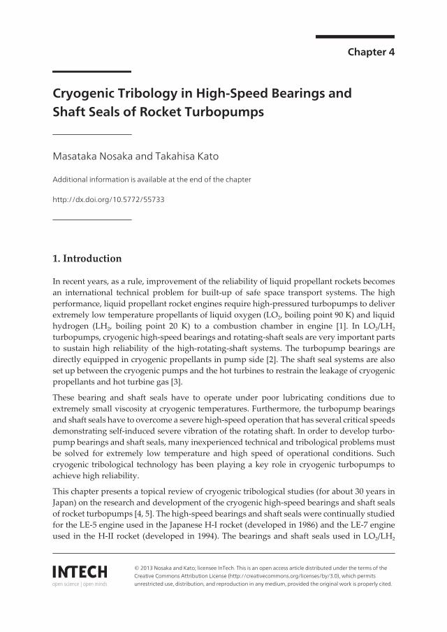


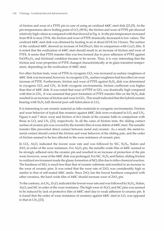


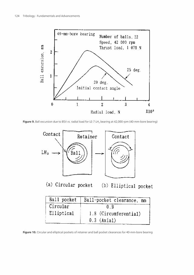


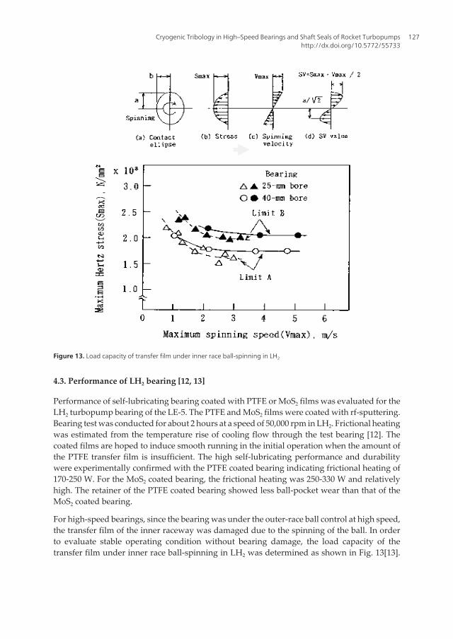
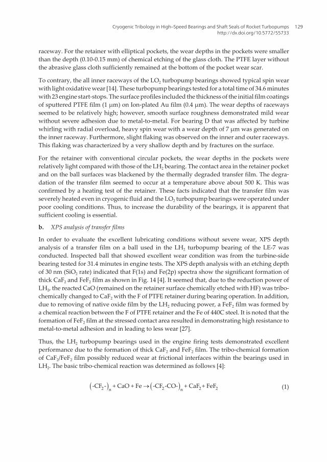

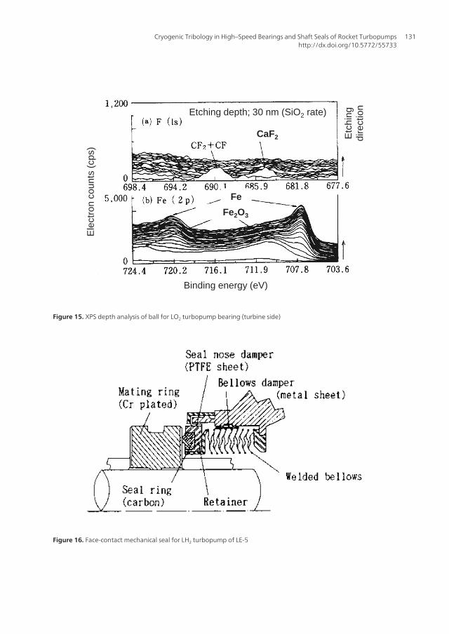
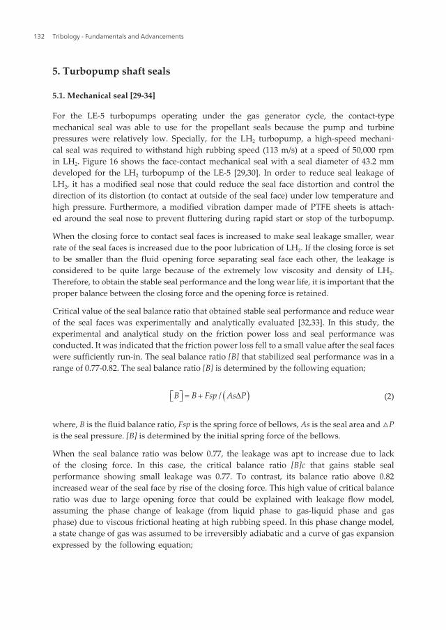

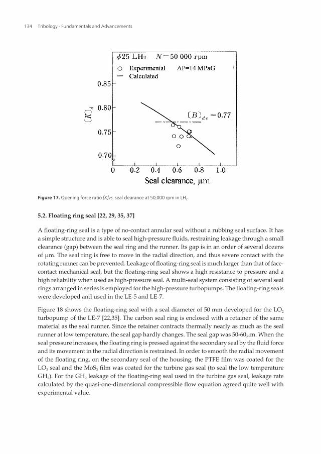
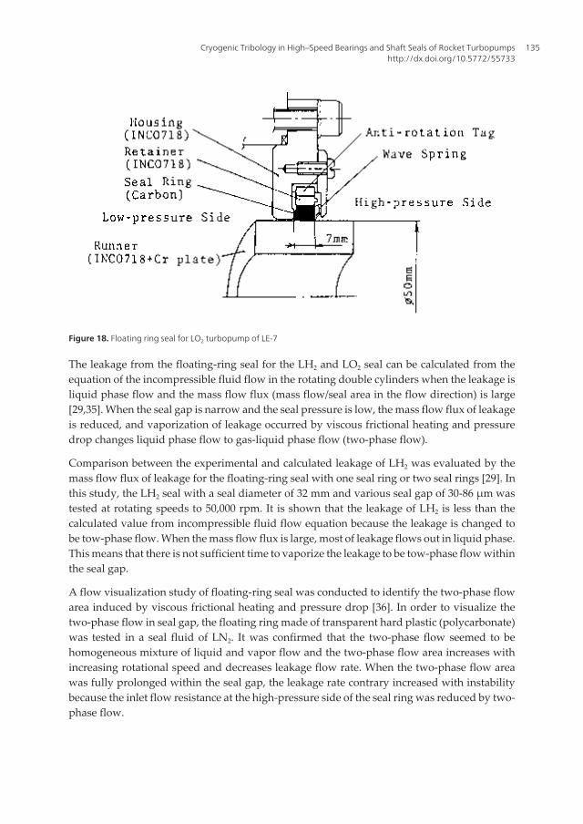


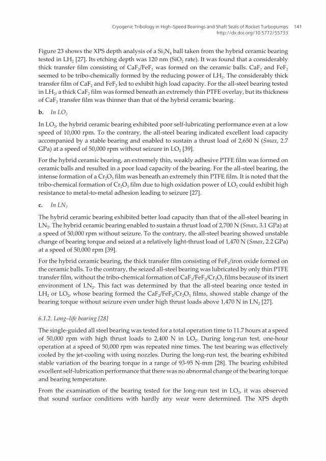
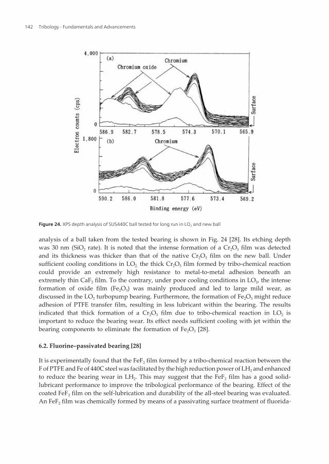

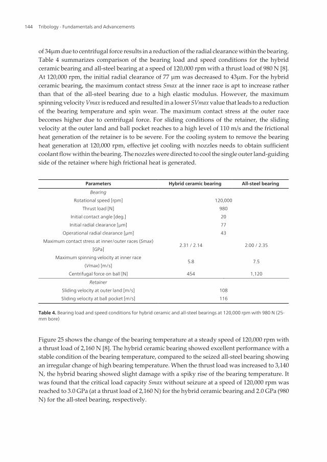


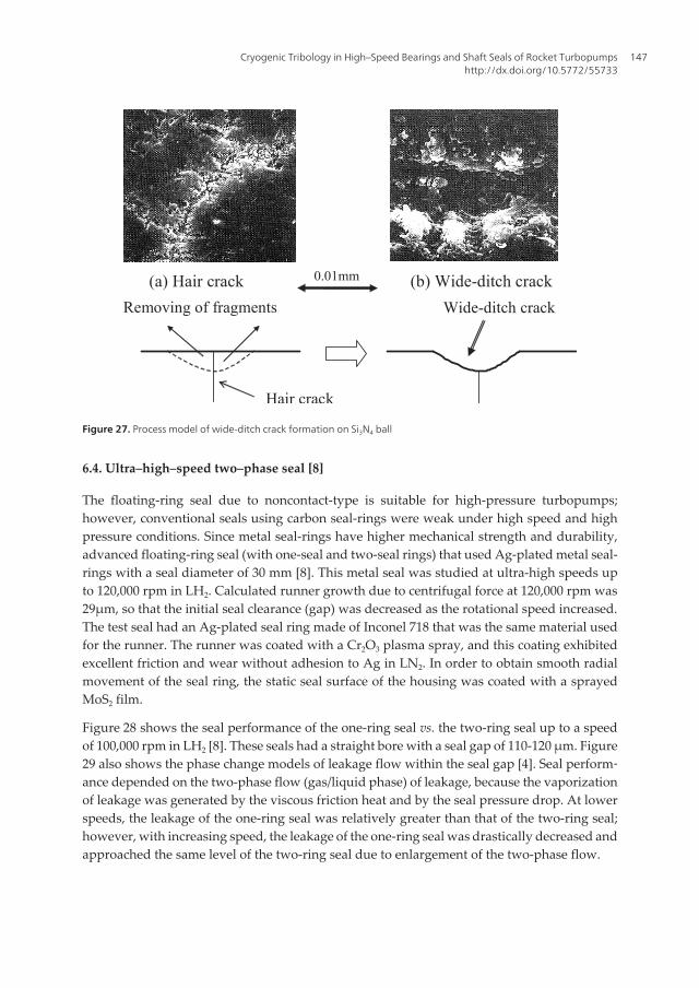


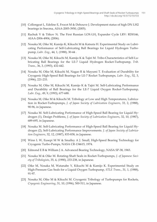
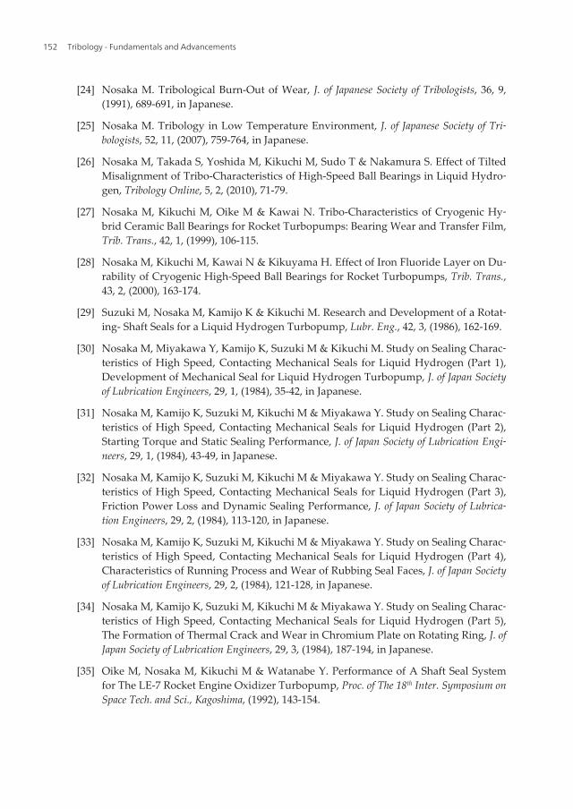


![The Development of a Cryogenic Over-Pressure Pump · cycle for the cryogenic over-pressure pump test. The timing sequence is a delay, discharge, and refill [1]. A 15s delay is meant](https://static.documents.pub/doc/80x56/5e7ec4ae07409d430d4bcce5/the-development-of-a-cryogenic-over-pressure-pump-cycle-for-the-cryogenic-over-pressure.jpg)
