95
Operated by the Jefferson Science Associates for the U.S. Dept. of Energy Page 1 Cryogenics @ JLab By JLab Cryo Group Presenter: VenkataRao Ganni January 25, 2011

Operated by the Jefferson Science Associates for the U.S. Dept. of Energy
Page 1
Cryogenics @
JLab
By
JLab Cryo Group
Presenter: VenkataRao Ganni
January 25, 2011

Operated by the Jefferson Science Associates for the U.S. Dept. of Energy
Page 2
Outline
• JLab Overview
• What is Cryogenics?
• Applications of Cryogenics
• Temperature Choice for Jlab Linacs
• Overview and Operation of Jlab cryogenic plants
• Down Time
• Utility Costs
• Other cryogenic group activities
• Education and R&D
• Support to other Labs
• Summary

Operated by the Jefferson Science Associates for the U.S. Dept. of Energy
Page 3
Jefferson Lab Overview
2000 member international user community engaged in exploring quark-gluon structure of matter
Superconducting accelerator provides 100% duty factor beams of unprecedented quality, with energies up to 6GeV and in future to 12GeV
CEBAF’s
innovative design
allows delivery of
beam with unique
properties to three
experimental halls
simultaneously
Each of the three halls offers complementary
experimental capabilities and allows for large
equipment installations to extend scientific reach
A C B
CHL

Operated by the Jefferson Science Associates for the U.S. Dept. of Energy
Page 4
JLab Site Overview
A B C
ARC CHL
LINAC
S

Operated by the Jefferson Science Associates for the U.S. Dept. of Energy
Page 5
What is Cryogenics?
Cryogenic Fluid Tsat @ 1 atm
[K]
Helium 4.22
Hydrogen 20.28
Neon 27.09
Nitrogen 77.31
Argon 87.28
Oxygen 90.19
Methane 111.69
The production of temperature below 123 K (-150 °C)
Examples of Cryogenic Fluids

Operated by the Jefferson Science Associates for the U.S. Dept. of Energy
Page 6
Temperature Scale Comparison
123K Start of Cryogenics
78K LN2
4.5K Experimental Halls/CTF
2.1K CEBAF/FEL LINACS

Operated by the Jefferson Science Associates for the U.S. Dept. of Energy
Page 7
Applications of Cryogenics
Cryogenics was primarily used for
Gas separation
Helium was first liquefied by Heike Kamerlingh Onnes on July 10th 1908, in Leiden (NL)
Onnes observed superconductivity in 1911 (100 Years ago!)
This lead to the application of Cryogenics to:
Physics research
Medical Applications (MRI Magnets)
Instruments
Other applications are:
Biological & Medical
Space research
Vacuum

Operated by the Jefferson Science Associates for the U.S. Dept. of Energy
Page 8
Applications of Cryogenics
Superconductivity:
No resistance below a critical temperature
This allows:
(a) Low temperature super-conductors (below 20 K)
used for magnets and RF cavities
(b) High temperature super-conductors (around 70 K Level) used for power leads
All these need Cryogenics

Operated by the Jefferson Science Associates for the U.S. Dept. of Energy
Page 9
Applications of Cryogenics
Particle Accelerators use magnets and RF cavities
At room temperature the iron core saturates at about 2 T, where as the magnets built with super conductors can be designed for large magnetic fields like 10 T and more and are compact
High frequency (~100 MHz to 3000 MHz) RF cavity designs typically use low temperature environment for efficient and high quality beam operation although there are exception like room temperature RF used from AM radio, under 1 MHz, to 11.4 GHz
For a given energy, the accelerators designed with superconductors require:
• Lower capital cost
— Since it requires fewer number of magnets and/or RF cavities
— Less length of the accelerator
• Lower operating cost
There fore for large accelerators, superconducting structures at cryogenic temperatures are a proven and cost effective
All large particle accelerators need Cryogenics

Operated by the Jefferson Science Associates for the U.S. Dept. of Energy
Page 10
Carnot Work Required at Various Temperatures
T_load Pcarnot
(K) W / W
A / C Sys. 263.0 0.14
Methane 111.7 1.69
Oxygen 90.2 2.33
Argon 87.3 2.44
Nitrogen 77.3 2.88
Neon 27.1 10.07
Hydrogen 20.3 13.79
Helium 4.2 70.09
Helium
@Lambda 2.2 137.25
Helium @ 2.0 K 2.0 149.00
Ideally (Min.) Required input Power per 1 W of Cooling (W/W)

Operated by the Jefferson Science Associates for the U.S. Dept. of Energy
Page 11
Operating Temperature Choice for CEBAF
Ref. CEBAF Design Report May 1986

Operated by the Jefferson Science Associates for the U.S. Dept. of Energy
Page 12
JLab Cryogenic Group Activities
• Operate existing plants
• Design new systems for JLab
• Design new systems for other labs
e.g., MSU, SNS, NASA, etc.
• Optimize the operation of existing systems for JLab
and other labs
e.g., MSU, SNS, BNL, NASA, etc.
• Support cryo R & D
• Support education

Operated by the Jefferson Science Associates for the U.S. Dept. of Energy
Page 13
Operation of the Helium Refrigeration System
Central Helium Liquefier (CHL) at JLab
Original Design TS Diagram

Operated by the Jefferson Science Associates for the U.S. Dept. of Energy
Page 14
Operation of the Existing Plants
• Operate existing plants
CHL 4600 W @ 2.1 K (Accelerator)
ESR 1500 W @ 4.5 K (Experimental Halls)
CTF 750 W @ 4.5 K (Test Facility)
Support the Continuous unattended operations
24/7/365
2 K operations started in 1994
Only once LINAC has been warmed up to date
–Hurricane Isabel in 2003

Operated by the Jefferson Science Associates for the U.S. Dept. of Energy
Page 15
Operation of the Existing Plants
• Maintain the equipment
• e.g., compressors, motors, vacuum pumps, turbines etc.
• Coordinate the maintenance activates on utilities
• e.g., cooling tower, electric power, etc.
• Coordinate the LN2 & helium gas deliveries
• Modify the equipment configurations
• i.e., “U” tube changes
• Operate the plants at the required capacity and at the
optimum operating conditions to meet the needs of
the various experiments and the accelerator
maintenance plans

Operated by the Jefferson Science Associates for the U.S. Dept. of Energy
Page 16
CHL Cryo Plant Capacities
• Existing CHL #1 supporting current 6 GeV
4.6 kW @ 2.1 K,
12 kW @ 35 K - 55 K and,
10 g/s liquefaction @ 4.5 K
• New CHL #2 to support future 12 GeV
4.6 kW @ 2.1 K,
12 kW @ 35 K – 55 K and,
15 g/s liquefaction @ 4.5 K (Presently Under Construction)

Operated by the Jefferson Science Associates for the U.S. Dept. of Energy
Page 17
CHL-I Compressor Room

Operated by the Jefferson Science Associates for the U.S. Dept. of Energy
Page 18
CHL-1 4.5 K Cold Box Installation

Operated by the Jefferson Science Associates for the U.S. Dept. of Energy
Page 19
CHL-II Compressor Installation Plans

Operated by the Jefferson Science Associates for the U.S. Dept. of Energy
Page 20
CHL-II Cold Box Installation Plans

Operated by the Jefferson Science Associates for the U.S. Dept. of Energy
Page 21
2K Technology
Cold Compressors
TORE SUPRA was the first application that used the partial (2 stage) cold compressors for 15 g/s of 2K flow,
assisted by warm sub atmospheric compression
CEBAF 2K design is the first one to use all (4 stage) cold compressors for the 2K flow of 235 g/s,
which is more than 15 times that of TORE SUPRA, resulted in substantial growing pains

Operated by the Jefferson Science Associates for the U.S. Dept. of Energy
Page 22
CHL-1 (4.5 K & 2 K CBX’s)
Original “2 K” (SCM) Cold Box
During the commissioning process Jlab:
• Added components (e.g.,HX-9A, etc.)
• Developed the new pump down process different from the original plans
• Cold Compressor - 2.1 K Operations to support CEBAF started in May of 1994
• Cryo system reliability & availability of ~75% was not acceptable to JLab operations

Operated by the Jefferson Science Associates for the U.S. Dept. of Energy
Page 23
New 2 K CBX (SCN)
Design Improvements:
•Five cold compressor stages in SCN
•Parallel LN2 thermo-siphon motor cooling
•Larger sub-cooler (4K to 2K) heat exchanger (HX-10N)
•Increased volume of inter-stage piping
•Circular inter-stage piping with flow straighteners
•Improved thermal isolation of compressors, valves, etc.
•Improved Ln2 heat shielding and heat stationing on valves and bayonets

Operated by the Jefferson Science Associates for the U.S. Dept. of Energy
Page 24
2K Cold Box (SCN) Operational Improvements
• Increased capacity > 10% (~500 W at 2 K)
• Increased operating envelope and stability
• Pump-down is fast and easy
• Commissioned in 3 days
• Continuously on-line since June 1999
• JLab modifying the original 2 K CBX (SCM) to
include all of the improvements made to the SCN

Operated by the Jefferson Science Associates for the U.S. Dept. of Energy
Page 25
Present 2 K System Capacity (Using SCN)
Pr Vs Flow
120130140150160170180190200210220230240250260
0.020 0.022 0.024 0.026 0.028 0.030 0.032 0.034 0.036 0.038 0.040
Linac Pressure (Atm)
Figure-6.2.1F
lo
w (g
/s)
FlowFlow Vs Q
0
500
1000
1500
2000
2500
3000
3500
4000
4500
5000
5500
6000
0 50 100 150 200 250 300
Flow (g/s)
Figure-5.2.1a
Qp
, Q
s,
Qto
t (
W)
Qp Qs Qtot

Operated by the Jefferson Science Associates for the U.S. Dept. of Energy
Page 26
Modified “2 K” Cold Box (SCM)
Original “2 K” cold box w/ modifications:
Near duplicate of existing operating “2 K” cold box (SCN)
Removed unreliable, large Linac return valve
• Nearly ready
• Requires cold check out

Operated by the Jefferson Science Associates for the U.S. Dept. of Energy
Page 27
2 K Cold Box (SCM) Internals

Operated by the Jefferson Science Associates for the U.S. Dept. of Energy
Page 28
Modified Original 2K CBX (SCM) with CHL-1

Operated by the Jefferson Science Associates for the U.S. Dept. of Energy
Page 29
JLab 2K Cryo Technology
• The 2 K Load of 4.6 kW is supported by a single plant;
which is the single largest 2 K cryo plant to date
• All compression for the 2 K load flow from sub
atmospheric condition to above atmospheric pressure
is accomplished at cryogenic temperatures. Only JLab
and the SNS plant (~ ½ the JLab cryo capacity)
designed by Jlab use this technology
• JLab 2 K Cryo system has been operating since 1994. In
1999 JLab built and commissioned a new 2 K cold box
(SCN) which improved the cryo system availability to
>98%. It has a very long reliable 2 K operational history

Operated by the Jefferson Science Associates for the U.S. Dept. of Energy
Page 30
Behind CHL

Operated by the Jefferson Science Associates for the U.S. Dept. of Energy
Page 31
Cryo Distribution at CHL to Linacs

Operated by the Jefferson Science Associates for the U.S. Dept. of Energy
Page 32
LINAC Transfer Lines
NEW FOR
12 GeV
NEW
12 GeV
600W @2.1K on SL

Operated by the Jefferson Science Associates for the U.S. Dept. of Energy
Page 33
A B C
JLab Transfer Lines
HALLS
CHL
ESR, 4 K
FEL, 2 K
CTF, 4 K
CHL + SBR,
2 K / 4 K 2 K
Linacs
TL To CTF Removed

Operated by the Jefferson Science Associates for the U.S. Dept. of Energy
Page 34
Transfer Line Cross Sections

Operated by the Jefferson Science Associates for the U.S. Dept. of Energy
Page 35
CEBAF Accelerator

Operated by the Jefferson Science Associates for the U.S. Dept. of Energy
Page 37
LINAC TL Configuration
• CURRENT 6 GeV:
CHL-1 supplies injector, north and south Linacs, FEL,
and 10 g/s to ESR
• NEW 12 GeV:
CHL-1: Injector, north Linac
CHL-2: South Linac and existing FEL
NOTE: IN CASE OF A CHL-1 OR CHL-2 MAINTANENCE or FAILURE,
THE LINACS CAN BE RECONNECTED TOGETHER INTO SINGLE
REMAINING CRYO PLANT FOR 6 GeV BEAM OPERATION

Operated by the Jefferson Science Associates for the U.S. Dept. of Energy
Page 38
Existing End Station Refrigeration System for Cryo Support of Experimental Halls
ESR-1 refrigerator (built in 1978) serves
experimental Halls A,B and C
Capacity of
1500 W @ 4.5 K helium refrigeration
OR
11 g/s 4.5 K liquefaction
(To support large target loads
the halls can also receive an additional
25 g/s 4.5 K liquid helium from CHL via. TL)

Operated by the Jefferson Science Associates for the U.S. Dept. of Energy
Page 39
ESR-1 Compressors

Operated by the Jefferson Science Associates for the U.S. Dept. of Energy
Page 40
ESR-1 Cold Box

Operated by the Jefferson Science Associates for the U.S. Dept. of Energy
Page 41
ESR-1 Distribution and Hall Interfaces

Operated by the Jefferson Science Associates for the U.S. Dept. of Energy
Page 42
ESR-1 Oil Removal & LHe Storage

Operated by the Jefferson Science Associates for the U.S. Dept. of Energy
Page 43
Transfer Line between CHL and ESR

Operated by the Jefferson Science Associates for the U.S. Dept. of Energy
Page 44
New ESR-2 Cryo Refrigeration System
for Experimental Halls
Additional refrigeration capacity for
experimental Halls A, B & C to support the
12 GeV program
SSCL refrigerator (fabricated in 1992)
has a capacity of
4 kW @ 4.5 K Helium Refrigeration
OR
5 kW @ 20 K Helium Refrigeration
OR
40 g/s 4.5 K Liquefaction

Operated by the Jefferson Science Associates for the U.S. Dept. of Energy
Page 45
4 kW ESR-2 (SSCL Cold Box) Installation

Operated by the Jefferson Science Associates for the U.S. Dept. of Energy
Page 46
Experimental Halls A, B & C
Cryogens are
supplied from ESR
to
Hall cryo magnets
and cryo targets

Operated by the Jefferson Science Associates for the U.S. Dept. of Energy
Page 47
Hall D Cryogenic System
Hall D 4.5 K Refrigerator (Built 1980)
Capacity is,
200 W @ 4.5 K Refrigeration
OR
2 g/s 4.5 K Liquefaction
Hall-D mixed load…0.7 g/s liquefaction
+
100 W Refrigeration (includes transfer line load)
Operated by the Jefferson Science Associates for the U.S. Dept. of Energy
Page 48
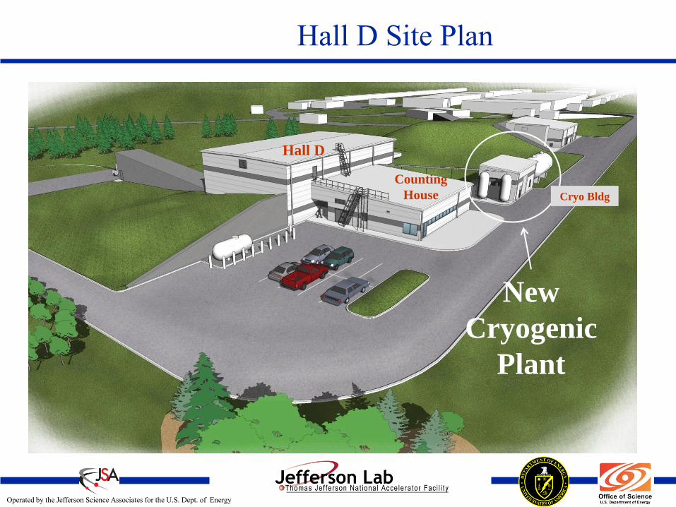
Hall D Site Plan
New
Cryogenic
Plant
Counting
House Cryo Bldg
Hall D

Operated by the Jefferson Science Associates for the U.S. Dept. of Energy
Page 49
Hall-D Planned Refrigeration Equipment
Model 2800 Refrigerator Helium Compressors

Operated by the Jefferson Science Associates for the U.S. Dept. of Energy
Page 50
Hall-D Experimental Setup

Operated by the Jefferson Science Associates for the U.S. Dept. of Energy
Page 51
Cryogenic Test Facility (CTF)
• Commission date: 1989
• Main compressors:
(3) 250 kW Mycom compound
screw compressors
• Control system:
EPICS software, CAMAC hardware
• Service duty:
24/7/365 continuous unattended
• Operational hours to date:
> 170,000 hrs

Operated by the Jefferson Science Associates for the U.S. Dept. of Energy
Page 52
Cryogenic Test Facility (CTF)
— KPS M2200 Helium Refrigerator (Cold Box #2)
• 4.5 K primary supply with warm vacuum
pumping for 2 K cryo-module and
superconducting cavity testing
• (2) reciprocating expansion engines
• Capacity, 700 W at 4.5 K, 4 g/s (120 L/hr)
4.5 K liquefaction
— CTI M2800 Helium Refrigerator (Cold Box #3)
• (2) Sulzer Turbine Expanders
• Capacity, 200 W at 4.5 K, 1.7 g/s (51 L/hr)
4.5 K liquefaction
— Helium Shield Refrigerator (Cold Box #1)
• 35 K shield supply for transfer line and
cryo-module shield
• (1) reciprocating expansion engine
• Capacity, 800 W at 35 K

Operated by the Jefferson Science Associates for the U.S. Dept. of Energy
Page 53
Vertical Test Area (VTA) and CM Test Cave

Operated by the Jefferson Science Associates for the U.S. Dept. of Energy
Page 54
Meeting the Ever Increasing Cryo Demands
Increasing CHL-I Capacity
• Original operating conditions
—At 4 GeV, 235 g/s at 2 K; i.e., the design with margin
—Cryo plant was forced to run at max. design point
—No redundant equipment (compressors or turbines)
• Improvements made:
—Implemented Floating Pressure Ganni Cycle to meet the
loads efficiently
—Replaced the old 2 K cold box with JLab design (1999)
—Added the Stand-By Refrigerator (SBR) cold box and
compressors
• Present conditions
—At 6 GeV (current max load), 235 g/s at 2 K
—At 4 GeV, 190 g/s at 2 K

Operated by the Jefferson Science Associates for the U.S. Dept. of Energy
Page 55
Meeting the Ever Increasing Cryo Demands
Innovative ideas to meet the ever increasing thirst for
increased cryo capacity from ESR and CTF users
— ESR: initial plan of 2 week operation of a 2 kW target
in 2003 became routine
• Used an air-ambient vaporizer at ESR
— ESR: Needed more capacity for Qweak experiment
• Designed & installed Refrigeration Recovery HX, to increase
capacity and efficiency
— CTF: Need more capacity for 12 GeV and ILC work
• Have designed and will install 10 kL LHe dewar with sub-
cooler ; anticipated to increase the available cryo capacity
and cryo operational efficiency by a factor of two

Operated by the Jefferson Science Associates for the U.S. Dept. of Energy
Page 56
ESR – RRHX Process Study

Operated by the Jefferson Science Associates for the U.S. Dept. of Energy
Page 57
CTF 10kL LHe Dewar

Operated by the Jefferson Science Associates for the U.S. Dept. of Energy
Page 58
Cryo Down Time
—Accounted as all time loss to scheduled beam
operations due to the cryogenics system to return
back to physics (data collecting)
—Includes time for the restoration of the entire plant
• The amount of time to recover from an outage is exponential
to the amount of time that the cryogenic plant is down
—Cryo down-time resulting in physics interruption
• 1999 through 2008 ~ 1.6% average down time
• 2008 to present down time ~ 2.5%
– Main compressor failure without redundancy
» ~60 hours of down time
– Problems with LINAC return flow oscillations during high ambient
temperatures

Operated by the Jefferson Science Associates for the U.S. Dept. of Energy
Page 59
Major Contributions to Down Time
• Typical utility failures
—Electrical power
• Power spikes
• Phase imbalance
—Cooling water
• Cooling tower accumulates debris
• Pumping system failures
—Instrument (control) air
• moisture contamination in pneumatic
control valve positioners

Operated by the Jefferson Science Associates for the U.S. Dept. of Energy
Page 60
Major Contributions to Down Time (Cont.)
• Control systems (CAMAC) — Old technology, uses lots of power, generates lots of
heat (more heat, higher failure rates).
— Laboratory grade hardware, not designed for industrial environment.
— Highest failure rates in control system; electric valve cards, crate controllers, power supplies.
— Replacement components are getting harder to find.
• Aging components in system
— Control cards
— Carbon purification systems
— Compressors
— Carbon steel components
• Vacuum Jackets
• Water Piping

Operated by the Jefferson Science Associates for the U.S. Dept. of Energy
Page 61
Utilities - Helium
• Helium
—Is a very precious fluid
• Low boiling point (4.2 K at 1 atm)
—Known reserves are very limited
—Mostly coexists with natural gas in a small percent
—Federal helium conservation program is shutdown
—We were the major exporters of helium so far but
will start importing in a few years
We need to conserve helium!

Operated by the Jefferson Science Associates for the U.S. Dept. of Energy
Page 62
Helium Gas Delivery to CHL-1

Operated by the Jefferson Science Associates for the U.S. Dept. of Energy
Page 63
Estimated Average Helium Inventory at JLab
Liquid Liters
CEBAF Linacs (North + South) 67600
FEL 5200
Halls A, B & C 6200
CHL 8000
ESR 5000
CTF 8000
Total 100,000

Operated by the Jefferson Science Associates for the U.S. Dept. of Energy
Page 64
Helium Usage per Fiscal Year (in kilo-liquid liters)
0
50
100
150
200
250
300
1995 1996 1997 1998 1999 2000 2001 2002 2003 2004 2005 2006 2007 2008 2009 2010
KLiq
Liters JLab’s entire
Helium inventory
is lost and replaced
on an average
one and half times a year

Operated by the Jefferson Science Associates for the U.S. Dept. of Energy
Page 65
LN2 Usage per Fiscal Year
0
500
1000
1500
2000
2500
3000
3500
4000
4500
1995 1996 1997 1998 1999 2000 2001 2002 2003 2004 2005 2006 2007 2008 2009 2010
kGallonIsabelle effect
Cold box HX-1 Oil
Contamination effect

Operated by the Jefferson Science Associates for the U.S. Dept. of Energy
Page 66
Utilities – Electric Power Implementation of Floating Pressure Ganni Cycle
Through the years the Cryogenics Group
has completed several phases of
technological improvement which have,
(1) Increased the plants operational
envelope while reducing the utility
requirement per unit load and,
(2) Allow its capacity to automatically
vary to match the cryogenic load.
As compared to the 1994, 4 GeV baseline, these
improvements continue to save $ 500,000 to $1,000,000
per year depending on the operational demand.

Operated by the Jefferson Science Associates for the U.S. Dept. of Energy
Page 67
Estimated Utility Use by Cryo Systems
(Including Isabelle effect in FY 2004)
Max Min Ave He Use kLiq-Liters/year 260 99 160 M$ /year $ 0.707 $ 0.268 $ 0.435
LN2 Use kGal/year 4176 2496 3130 Equiv. Elec. Power (MW) 1.23 0.74 0.93 M$ /year $ 0.991 $ 0.592 $ 0.743
Electric Power CHL (MW) 6.5 4.5 ESR (MW) 1 0.7 CTF (MW) 1 0.6 M$/year $ 3.72 $ 2.54 $ 3.13
Total (M$/year) $ 5.42 $ 3.40 $ 4.31

Operated by the Jefferson Science Associates for the U.S. Dept. of Energy
Page 68
Estimated Utility Use by Cryo Systems
(Without Isabelle effect in FY 2004)
Max Min Ave He Use kLiq-Liters/year 226 99 153 M$ /year $ 0.614 $ 0.268 $ 0.417
LN2 Use kGal/year 3943 2496 3061 Equiv. Elec. Power (MW) 1.17 0.74 0.91 M$ /year $ 0.936 $ 0.592 $ 0.727
Electric Power CHL (MW) 6.5 4.5 ESR (MW) 1 0.7 CTF (MW) 1 0.6 M$/year $ 3.72 $ 2.54 $ 3.13
Total (M$/year) $ 5.27 $ 3.40 $ 4.28

Operated by the Jefferson Science Associates for the U.S. Dept. of Energy
Page 69
Education
JLab Cryo Group R&D
and
Educational Efforts

Operated by the Jefferson Science Associates for the U.S. Dept. of Energy
Page 70
Optimal Operating Parameters for JLab Cold Compressors
Masters Thesis: Joe Wilson Jr. (May 2003)

Operated by the Jefferson Science Associates for the U.S. Dept. of Energy
Page 71
Design of a Small 2K Cryo System
Masters Thesis: Peter N. Knudsen (May 2008)
Configurations C2-A, C2-A-p and C2-B Flow
Diagrams.
Configuration C2-A-p Real COPINV vs. Flow Ratio for 12 atm. Supply Pressure.

Operated by the Jefferson Science Associates for the U.S. Dept. of Energy
Page 72
Design and Development of Helium Purifier
Masters Thesis: Mat. Wright (May 2009)

Operated by the Jefferson Science Associates for the U.S. Dept. of Energy
Page 73
Capacity & Efficiency Improvements of a Small Cryo System
Masters Thesis: Errol Yuksek (Dec. 2009)

Operated by the Jefferson Science Associates for the U.S. Dept. of Energy
Page 74
Helium Refrigeration Systems Present State of the Art

Operated by the Jefferson Science Associates for the U.S. Dept. of Energy
Page 75
Floating Pressure Ganni Cycle
General Arrangement for Floating Pressure Process Cycle (patent pending)
The compressor and expander establish
an essentially constant pressure ratio and constant system Carnot efficiency

Operated by the Jefferson Science Associates for the U.S. Dept. of Energy
Page 76
Floating Pressure Ganni Cycle
As the “Claude Cycle” is essentially a constant pressure process
and, the “Sterling Cycle” is a constant volume process
the “Floating Pressure Cycle” is a constant pressure ratio process
That maintains essentially constant Carnot efficiency
over a very wide operating range
(100% to ~ 40% of maximum capacity in practical systems)
,2,2
,1 ,1
1 Constant
hh v Cr
x pl l
Tp Qp
p C T
ConstantL Lcarnot
C CW w

Operated by the Jefferson Science Associates for the U.S. Dept. of Energy
Page 77
Helium Screw Compressor System Advancements

Operated by the Jefferson Science Associates for the U.S. Dept. of Energy
Page 78
R& D Summary
• Jlab’s Collins Cryogenic Institute is actively
supporting helium cryogenic applied R&D in support
of the research community
• R&D is shared in collaborations with industry and
other labs and are combined with engineering thesis
work
• Focus areas include efficiencies of process cycles
(existing and planned), utilities, equipment design,
manpower, and maintenance/repair
• The derived technologies are being actively
integrated into industry and a growing number of
user facilities

Operated by the Jefferson Science Associates for the U.S. Dept. of Energy
Page 79
Support
JLab Cryo Support
to
Other Labs

Operated by the Jefferson Science Associates for the U.S. Dept. of Energy
Page 80
Upgrade to MSU Helium Refrigeration System (Bureau of Mines Liquefier)

Operated by the Jefferson Science Associates for the U.S. Dept. of Energy
Page 81
Upgrade to MSU Helium Refrigeration System (cont.)
Cryogenic system upgrade for the National Superconducting Cyclotron Laboratory (i.e., MSU):
• Upgrade to MSU refrigerator was originally designed as a liquefier for the Bureau of Mines (BOM) in Amarillo, TX (1979).
• Original BOM plant was designed as a pure liquefier system but has been arranged (by JLab) to operate efficiently primarily as a refrigerator over varying load requirements and also to support a mix of refrigeration and liquefaction loads.
• Compressor discharge pressure follows the load requirement (floating pressure Ganni cycle), reducing the required input utilities at reduced loads as well as reducing the wear and tear on the equipment.
• System has been operating continuously for the past ten years with more than 99% system availability.

Operated by the Jefferson Science Associates for the U.S. Dept. of Energy
Page 82
Design and Optimal Operation of SNS Helium Refrigeration System

Operated by the Jefferson Science Associates for the U.S. Dept. of Energy
Page 83
JLab Designed and Integrated SNS Plant and Sub-Systems
Helium Compressor 4.5 K Cold Box
SNS 2 K Cold Box Oil Removal System Gas Storage Vessels
LN2 Storage Dewar

Operated by the Jefferson Science Associates for the U.S. Dept. of Energy
Page 84
Design and Optimal Operation of SNS Helium Refrigeration System (cont.)
• JLab cryogenic group was responsible for the design, procurement, and fabrication of equipment, as well as, the integration and commissioning support for the SNS cryogenic system.
• SNS cryogenic system has been operating continuously since 2005
• System is presently set to operate at approximately optimum conditions for the majority of the operating modes by implementing the floating pressure – Ganni cycle.
The SNS system would have used 3.8 MW of equivalent input power with out the floating pressure Ganni cycle technology and it can be turn down to ~70% (approx. 2.7 MW) of equivalent input power or anywhere in between based on the refrigeration needs of the accelerator.

Operated by the Jefferson Science Associates for the U.S. Dept. of Energy
Page 85
Modifications and Optimal Operation of BNL Helium Refrigeration System
• Refrigeration system for Brookhaven National Lab
(BNL) was originally designed for the Isabelle project
with a capacity of 24.8 kW @ 3.8 K without LN2 pre-
cooling and capable of supporting some 2.5 K
temperature operations
• (Original) Isabelle refrigerator at BNL now used to
support RHIC, which operates at 4.5 K (instead of 3.8 K)
and requires a third of the system’s original capacity
• Project consisted of three phases (I, II and III).

Operated by the Jefferson Science Associates for the U.S. Dept. of Energy
Page 86
Modifications and Optimal Operation of BNL Helium Refrigeration System

Operated by the Jefferson Science Associates for the U.S. Dept. of Energy
Page 87
BNL RHIC Energy Savings at the Completion of Phase III
5.1
MW
Electric Power History Graph, (Phase III “Goal” 5.4MW)
7.2 MW
Exceeded 2003 Goal of 5.4MW……46% Electrical Power
Reduction Presently (2010) it is at 4.8 MW
9.4 MW
6.1 MW

Operated by the Jefferson Science Associates for the U.S. Dept. of Energy
Page 88
NASA-JSC/JLab Collaboration
James Webb Telescope
Replaces Hubble
at ~1 million miles out
Telescope Mockup at the National Mall, D.C.
Floating Pressure Technology Used For Telescope Testing
in the Environmental Space Simulation Chamber-A at JSC
Existing 3.5 kW 20K helium cryogenic system was converted to
JLab’s Floating Pressure Technology
Resulted in an improved temperature stability from 2.5 to 0.25 K
and improved efficiency
New 14kW 20K helium refrigerator design is based on the Floating Pressure Cycle

Operated by the Jefferson Science Associates for the U.S. Dept. of Energy
Page 89
NASA-JSC 3.5kW 20 K Refrigeration Test Results After JLab Mods (2008)
Original 3.5kW Plant
Modified 3.5kW Plant
to Floating Pressure
Planned 14 kW 20K
Plant Design
Operated by the Jefferson Science Associates for the U.S. Dept. of Energy
Page 90
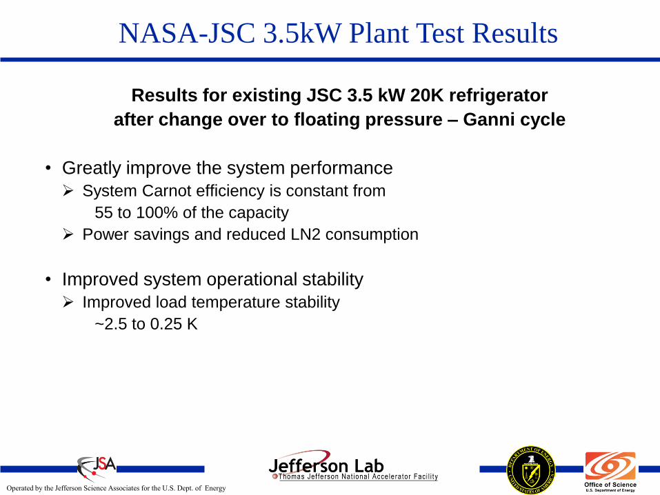
Results for existing JSC 3.5 kW 20K refrigerator
after change over to floating pressure – Ganni cycle
• Greatly improve the system performance
System Carnot efficiency is constant from
55 to 100% of the capacity
Power savings and reduced LN2 consumption
• Improved system operational stability
Improved load temperature stability
~2.5 to 0.25 K
NASA-JSC 3.5kW Plant Test Results

Operated by the Jefferson Science Associates for the U.S. Dept. of Energy
Page 91
NASA-JSC New 14 kW 20K Plant Design
Efficiencies for Partial Loads At 20K
0%
5%
10%
15%
20%
25%
30%
35%
0 2 4 6 8 10 12 14Load [kW]
Syste
m C
arn
ot
Eff
icie
ncy
20K, 1 Turbine
Turn-down at 20 K Load Return Temperature Efficiencies At 100% Loads
0%
5%
10%
15%
20%
25%
30%
35%
0 20 40 60 80 100Load [kW]
Syste
m C
arn
ot
Eff
icie
ncy
100% Loads at Various Load Return Temperatures
Efficiencies for Partial Loads At 100K
0%
5%
10%
15%
20%
25%
30%
35%
0 20 40 60 80 100Load [kW]
Syste
m C
arn
ot
Eff
icie
ncy
100K, 2 Turbines
100K, 1 Turbine
Turn-down at 100 K Load Return Temperature
Operated by the Jefferson Science Associates for the U.S. Dept. of Energy
Page 92
JLab Support to Other Labs (cont.)
Common in all these Jobs:
Floating Pressure operation, NOT forcing the
plant to follow the design TS, is one of the key
factors in being able to adopt to different load
conditions efficiently

Operated by the Jefferson Science Associates for the U.S. Dept. of Energy
Page 93
Summary
Jefferson Lab has established itself as the US technology leader in the cryogenic area by original, successful and repeated results in cryogenic systems design, fabrication, installation, commissioning, as well as, 24/7 operation expertise for more than 15 years of both 2 K and 4.5 K systems with an unprecedented cryogenic systems availability.
JLab provided the system designs for its own cryo systems like the 2 K cold box’s (SCN and modified SCM), ESR and SBR, transfer lines, as well as, designing and supervising the installation of cryo and distribution systems at other labs; such as MSU and SNS.
JLab is the only one in the US (for both the laboratories and the industry) with 2 K system design, fabrication, installation and commissioning
expertise that has been demonstrated multiple times.
JLab regularly participates in many other lab cryogenic system planning and development activities. These include the FSU, FERMI, MSU, SNS,BNL, and NASA.

Operated by the Jefferson Science Associates for the U.S. Dept. of Energy
Page 94
Summary
Jefferson Lab developed and patented the floating pressure Ganni Cycle technology. Application of parts of this technology and other improvements to BNL resulted in ~50% reduction in power (more than $50K per week) in energy savings.
Jefferson Lab has applied the floating pressure technology to all the plants at JLab, MSU, SNS, BNL and NASA to minimize the operating power.
Jefferson Lab has multiple operating cryogenic systems. They all have been automated to operate at optimal conditions (minimal energy input to the system) for varying loads and with minimal operating staff as compared other labs.
JLab’s senior staff has multiple decades of both industrial and lab experience in the process analysis, mechanical design, fabrication, installation, commissioning and optimal operation of large scale cryo systems.
JLab is presently involved in the cryogenic systems design for its own 12GeV upgrade, NASA James Web telescope testing, MSU FRIB project as others.

Operated by the Jefferson Science Associates for the U.S. Dept. of Energy
Page 95
Awards
2006 DOE Office of Science
Pollution Prevention and
Environmental Stewardship P2
“Best in Class Award”
2007 White House
Closing the Circle Award
Washington, DC

Operated by the Jefferson Science Associates for the U.S. Dept. of Energy
Page 96
Questions?


