Crystalline optical cavity at 4 K with thermal noise limited instability and ultralow drift J OHN M. ROBINSON 1, * ,E RIC OELKER 1 ,WILLIAM R. MILNER 1 ,WEI Z HANG 1, † , T HOMAS L EGERO 2 ,DAN G. MATEI 2, ‡ ,F RITZ RIEHLE 2 ,UWE S TERR 2 , AND J UN Y E 1 1 JILA, NIST and University of Colorado, 440 UCB, Boulder, Colorado 80309, USA 2 Physikalisch-Technische Bundesanstalt, Bundesallee 100, 38116 Braunschweig, Germany † Current address : National Institute of Standards and Technology 325 Broadway, Boulder, CO 80305, USA ‡ Current address : Horia Hulubei National Institute of Physics and Nuclear Engineering, Reactorului 30, 077125 Magurele, Romania * Corresponding author: [email protected]Compiled December 11, 2018 Crystalline optical cavities are the foundation of today’s state-of-the-art ultrastable lasers. Building on our previous silicon cavity effort, we now achieve the fundamental thermal noise-limited stability for a 6 cm long silicon cavity cooled to 4 Kelvin, reaching 6.5 × 10 -17 from 0.8 to 80 seconds. We also report for the first time a clear linear dependence of the cavity frequency drift on the incident optical power. The lowest fractional frequency drift of -3 × 10 -19 /s is attained at a transmitted power of 40 nW, with an extrapolated drift approaching zero in the absence of optical power. These demonstrations provide a promising direction to reach a new performance domain for stable lasers, with stability better than 1 × 10 -17 and fractional linear drift below 1 × 10 -19 /s. Ultrastable lasers are at the core of the world’s best precision measurements, including optical atomic clocks [1, 2], tests of relativity [3, 4], and gravitational wave detectors [5]. Improved optical coherence will open the door for more precise optical clocks [6, 7]. These lasers will further studies in fundamental physics in several aspects, including the search for dark mat- ter [8], atom-based gravitational wave detectors [9] and many- body physics [10]. Furthermore, optical clocks will play a defin- ing role in the next generation of optical timescales [11–13]. All of these applications greatly benefit from improved short, mid, and long-term laser frequency stability. In this paper, we present critical advancements in the devel- opment of a cryogenic ultrastable optical cavity. Performance of ultrastable optical cavities is typically evaluated with respect to the fundamental thermal noise floor. A silicon cavity cooled to a temperature of 124 K, which corresponds to the first zero- crossing point for the silicon thermal expansion coefficient, has demonstrated a thermal noise-limited frequency stability [14]. Using a closed-cycle cryocooler to reach 4 K where the silicon thermal expansion asymptotically approaches zero, a cryogenic 6-cm long silicon cavity has already demonstrated fractional fre- quency instability of 1 × 10 -16 [15]. With improved thermal and vibration isolation, optical feedback management, and cavity locking, we have improved the performance of this system at all averaging times. Short-term noise is optimized by reducing the impact of vi- brations and other technical noise sources, unveiling the thermal noise floor for the first time for a 4 K optical cavity. Through a fre- quency comparison with a reference laser (named Si3) [14], we demonstrate instability at the thermal noise floor of 6.5 × 10 -17 for averaging times of 0.8 to 80 seconds. Furthermore, we make the discovery that the frequency drift depends linearly on the incident power. The drift decreases as the circulating optical power is reduced, extrapolating to a zero drift when the incident power is zero. The lowest drift is attained at a transmitted power of 40 nW, giving a fractional frequency drift of -3 × 10 -19 /s. This constitutes the first demonstration of thermal noise limited performance at 4 K and the discovery of a power-dependent drift of a cryogenic optical cavity. The schematic of the 4 K silicon cavity system (Si4) is shown in Fig. 1. The 6 cm long cavity is enclosed in a three-stage cryo- genic thermal damping system formed by an outer radiation shield (thick blue cylinder in Fig. 1a), and two inner shields near 4 K (thin orange) [15]. Room temperature coupling to the cavity is especially important due to the T 4 scaling of the ra- diative power. To address this, we optimized the design of the outermost cryogenic shield. We changed the material from alu- minum to copper and added active temperature stabilization. Copper has a thermal conductivity 100 times larger than that of aluminum at 40 K, leading to a more homogeneous and lower arXiv:1812.03842v1 [physics.ins-det] 6 Dec 2018
Transcript
Crystalline optical cavity at 4 K with thermal noiselimited instability and ultralow driftJOHN M. ROBINSON1, *, ERIC OELKER1, WILLIAM R. MILNER1, WEI ZHANG1, †,THOMAS LEGERO2, DAN G. MATEI2, ‡, FRITZ RIEHLE2, UWE STERR2, AND JUNYE1
1JILA, NIST and University of Colorado, 440 UCB, Boulder, Colorado 80309, USA2Physikalisch-Technische Bundesanstalt, Bundesallee 100, 38116 Braunschweig, Germany†Current address : National Institute of Standards and Technology 325 Broadway, Boulder, CO 80305, USA‡Current address : Horia Hulubei National Institute of Physics and Nuclear Engineering, Reactorului 30, 077125 Magurele, Romania*Corresponding author: [email protected]
Compiled December 11, 2018
Crystalline optical cavities are the foundation oftoday’s state-of-the-art ultrastable lasers. Buildingon our previous silicon cavity effort, we nowachieve the fundamental thermal noise-limitedstability for a 6 cm long silicon cavity cooledto 4 Kelvin, reaching 6.5 × 10⁻¹⁷ from 0.8 to 80seconds. We also report for the first time a clearlinear dependence of the cavity frequency drift onthe incident optical power. The lowest fractionalfrequency drift of −3 × 10⁻¹⁹/s is attained at atransmitted power of 40 nW, with an extrapolateddrift approaching zero in the absence of opticalpower. These demonstrations provide a promisingdirection to reach a new performance domain forstable lasers, with stability better than 1 × 10⁻¹⁷
and fractional linear drift below 1 × 10⁻¹⁹/s.
Ultrastable lasers are at the core of the world’s best precisionmeasurements, including optical atomic clocks [1, 2], tests ofrelativity [3, 4], and gravitational wave detectors [5]. Improvedoptical coherence will open the door for more precise opticalclocks [6, 7]. These lasers will further studies in fundamentalphysics in several aspects, including the search for dark mat-ter [8], atom-based gravitational wave detectors [9] and many-body physics [10]. Furthermore, optical clocks will play a defin-ing role in the next generation of optical timescales [11–13]. Allof these applications greatly benefit from improved short, mid,and long-term laser frequency stability.
In this paper, we present critical advancements in the devel-opment of a cryogenic ultrastable optical cavity. Performance
of ultrastable optical cavities is typically evaluated with respectto the fundamental thermal noise floor. A silicon cavity cooledto a temperature of 124 K, which corresponds to the first zero-crossing point for the silicon thermal expansion coefficient, hasdemonstrated a thermal noise-limited frequency stability [14].Using a closed-cycle cryocooler to reach 4 K where the siliconthermal expansion asymptotically approaches zero, a cryogenic6-cm long silicon cavity has already demonstrated fractional fre-quency instability of 1× 10⁻¹⁶ [15]. With improved thermal andvibration isolation, optical feedback management, and cavitylocking, we have improved the performance of this system at allaveraging times.
Short-term noise is optimized by reducing the impact of vi-brations and other technical noise sources, unveiling the thermalnoise floor for the first time for a 4 K optical cavity. Through a fre-quency comparison with a reference laser (named Si3) [14], wedemonstrate instability at the thermal noise floor of 6.5 × 10⁻¹⁷
for averaging times of 0.8 to 80 seconds. Furthermore, we makethe discovery that the frequency drift depends linearly on theincident power. The drift decreases as the circulating opticalpower is reduced, extrapolating to a zero drift when the incidentpower is zero. The lowest drift is attained at a transmitted powerof 40 nW, giving a fractional frequency drift of −3 × 10⁻¹⁹/s.This constitutes the first demonstration of thermal noise limitedperformance at 4 K and the discovery of a power-dependentdrift of a cryogenic optical cavity.
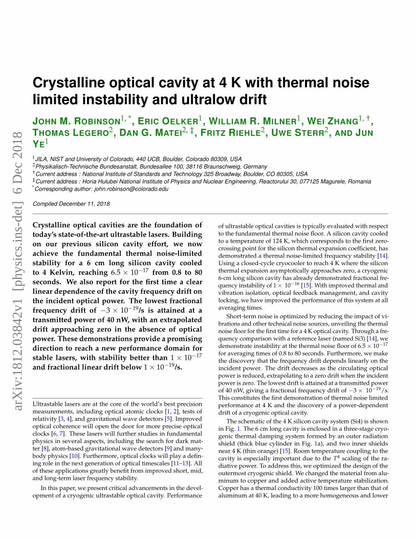
The schematic of the 4 K silicon cavity system (Si4) is shownin Fig. 1. The 6 cm long cavity is enclosed in a three-stage cryo-genic thermal damping system formed by an outer radiationshield (thick blue cylinder in Fig. 1a), and two inner shieldsnear 4 K (thin orange) [15]. Room temperature coupling to thecavity is especially important due to the T4 scaling of the ra-diative power. To address this, we optimized the design of theoutermost cryogenic shield. We changed the material from alu-minum to copper and added active temperature stabilization.Copper has a thermal conductivity 100 times larger than that ofaluminum at 40 K, leading to a more homogeneous and lower
arX
iv:1
812.
0384
2v1
[ph
ysic
s.in
s-de
t] 6
Dec
201
8
Fig. 1. Schematic of the optical cavity setup and measurement system. The 1.5 µm laser is stabilized to the 4 K cavity using Pound-Drever-Hall (PDH) locking. The cryostat is connected to the main chamber (black) and the cryogenic shields through a flexiblevacuum bellows. The blue shield is stabilized near 40 K and encloses two inner shields near 4 K (orange). The optical power iscontrolled in transmission. Si3 is shown on the right, which consists of a 1.5 µm laser locked to a 124 K silicon cavity. The Si3 laserstability and drift are measured by a strontium optical lattice clock. The drift of Si3 is confirmed by comparing the repetition rate ofan Er:fiber frequency comb locked to Si3 versus a hydrogen maser which is directly calibrated by the UTC(NIST) timescale.
temperature thermal shield. These improvements lead to a re-duced coupling of room temperature variations to the cavityfrequency from 200 Hz/K to 4 Hz/K. In order to support mHzlevel instability, we now require only mK level control of theroom temperature enclosure.
Vibrations are the primary source of short-term instabilityfor our system. We minimize vibrations coming from the cry-ocooler by carefully designing the mechanical layout of thesystem [15]. Due to the anisotropic nature of the silicon crys-tal [16], we were able to reduce the vertical vibration sensitivityto (5 ± 2)× 10−12/g at a driving frequency of 9.5 Hz. The hori-zontal vibration sensitivity in each direction was measured tobe (2 ± 1)× 10−10/g. A reduction of vibrations at the cavitywas obtained by fine tuning the relative position of the vacuumchamber and the cryostat. The combined improvements in sen-sitivity and noise provide a tenfold reduction in the frequencynoise power spectral density (PSD) for Fourier frequencies of10-50 Hz compared to previous work [15].
Two other critical noise sources are residual amplitude modu-lation (RAM) and intensity fluctuations. We control RAM to theppm level by employing active RAM cancellation [17]. Intensityfluctuations in transmission couple to the fractional frequency ofthe cavity with a sensitivity of 1 × 10⁻¹²/µW near DC. To elimi-nate this noise source, we stabilize fluctuations in the transmittedoptical power to the picowatt level by using a photodetector andfeeding back to an acousto-optic modulator before the cavity.This both ensures that the intensity-induced frequency fluctua-tions are below the thermal noise floor and provides a way tochange the power for investigating the cavity frequency drift.
To determine the instability of the Si4 cavity, we measure abeat between Si4 and Si3 (see Fig. 1). Si3 consists of a 1.5 µmlaser stabilized to a silicon cavity which operates at 124 K witha thermal noise floor of 4 × 10⁻¹⁷ [14, 16]. The short-term in-stability (averaging times of 0.1 to 10 s) of Si3 is determined bya three-cornered comparison with Si4 and a ULE clock laser at698 nm. The long-term instability (>10 s) is directly measuredby a strontium optical lattice clock. These measurements showthat Si3 is at its thermal noise floor for averaging times from 0.1to 1000 s [18].
The modified Allan deviation of this beat, after subtractingthe reference laser instability of 4 × 10⁻¹⁷ in quadrature, is dis-played in Fig. 2(A). The modified Allan deviation is calculatedfrom a 24,000 second long measurement record made with adead-time free lambda-type counter. We compute the instabil-ity after removing the linear drift of the beat with a magnitudeof ∼ 3 × 10⁻¹⁸/s. The Si4 instability reaches 6.5 × 10⁻¹⁷ foraveraging times of 0.8 < τ < 80 s, which is consistent withthe predicted thermal noise floor (green shaded region). Theuncertainty in the thermal noise floor arises from the spread inthe loss angle at 4 K [19, 20].
The corresponding frequency noise PSD for Si4 is shown inFig. 2(B). The PSD is calculated from the time-series of the beatobtained by the frequency counter. The thermal noise floor ofthe Si3 cavity (Sy = 1.7 × 10⁻³³/ f ) is subtracted from the beatPSD [14]. The Si4 laser is limited by the thermal noise floor forFourier frequencies over nearly three decades, from 5 mHz to2 Hz. We fit the measured PSD to a function Sy = a f−1 andobtain the fit parameter a = 4.12(5) × 10−33. Using the fullexpression given in [21], the Young’s modulus and Poisson’sratio from [22], we extract a loss angle for the SiO2/Ta2O5 mirrorcoatings to be φ = 5.1(5)× 10−4. The thin noise spikes at 1 Hzand higher harmonics come from the cryocooler vibrations. Thelaser deviates from thermal noise at Fourier frequencies below0.5 mHz, potentially due to etalons or temperature fluctuations.
We experimentally determine the laser linewidth from a FastFourier Transform (FFT) of the Si3-Si4 beat. The beat is mixeddown to 10 Hz and digitized with a analog-to-digital converter.One example of such a measurement is shown in Fig. 3(A). Weuse a measurement time of 128 seconds and employ a Hanningwindow, corresponding to a Fourier limit of 10.9 mHz. Theexpected linewidth for 1/ f frequency noise is given by a sta-tistical distribution [14]. The distribution is multiplied by the
ratio σSi4/(√
σ2Si3 + σ2
Si4) = 0.85 in order to estimate the rela-tive contribution of the Si4 cavity to the beat linewidth. Here,σSi4(Si3) refers to the thermal noise floor of Si4(Si3). We repeatthis measurement 100 times and plot the histogram of resultsin Fig. 3(B). The median laser linewidth for the distribution inFig. 3(B) is 16 mHz, which represents the lowest observed to
Fig. 2. (A) Modified Allan deviation for the Si4 cavity. (B) Frac-tional frequency noise power spectral density (Sy) of the Si4cavity. In both panels, the shaded green is the predicted ther-mal noise floor.
date for an optical cavity placed inside a closed-cycle cryocooler.We measure the drift of the Si4 system by counting the beat
Si3-Si4 as shown in Fig. 1. This requires careful calibration ofthe drift of the Si3 system. The Si3 laser is used as the clock laserfor a strontium optical lattice clock, giving a direct measurementof the drift [18]. As an independent check, the drift of the Si3system is continuously monitored against a hydrogen maserfrom NIST via an optical frequency comb. This maser is thencalibrated against UTC(NIST) as depicted in Fig. 1. The long-term linear frequency drift of Si3 is −3× 10⁻¹⁹/s with 2.8 µW oftransmitted power. The measured linear drift of Si3 is removedfrom the Si3-Si4 beat, thus giving the drift of Si4.
The linear frequency drift of the Si4 cavity is dependent onthe transmitted optical power as shown in Fig. 4(A). We vary theincident power and stabilize the cavity transmission at variouslevels as shown in Fig. 1. With a cavity finesse of F = 500, 000and a transmission coefficient of T = 2 ppm, a transmittedpower of 40 nW corresponds to a circulating optical power of2 mW. Each time the optical power in the cavity is changed, a fre-quency transient is observed with a characteristic time constantbetween 1 and 2 days. In order to extract the linear frequencydrift, we typically wait several time constants for the transientto decay away. When the drift is low (at lower optical power),we wait even longer in order to avoid the contribution from thetransient. For example, as shown in the inset of Fig. 4(B), we wait5 time constants before fitting a linear drift. We achieve highperformance at low optical power by employing resonant pho-todetectors for both the PDH and the RAM detection, providinga shot-noise limited signal-to-noise ratio at 68 nW.
The linear power dependence of the drift is striking evidencefor a new mechanism of length drift of an optical cavity at low
Fig. 3. (A) FFT of the beat measured at 1542 nm (black circles),fit to a Lorentzian lineshape (red line). (B) Histogram of themeasured Si4 linewidths for 100 measurements.
temperatures. The sign of the frequency drift is always negative,meaning the cavity is getting longer over time. The slope ofthe power dependence is roughly −7 × 10⁻²¹/s/nW. One po-tential explanation is thermal-induced mechanical creep of themirror coating, where the mismatch in the coefficient of thermalexpansion for the substrate and the coating gives a temperature-dependent creep. To reduce the impact of optical power on thelong-term drift, Wiens et al. minimized the irradiation of theirmirrors by periodically scanning the laser across the cavity reso-nance to measure the cavity frequency [4]. We present the firstrigorous characterization of a power-dependent frequency driftin an optical cavity.
The lowest operating power we have achieved is 40 nW intransmission, giving a fractional frequency drift of −3× 10⁻¹⁹/s.This frequency drift is comparable to the previous state-of-the-art obtained from a 124 K silicon cavity [23]. However, theimplication of the current finding is tantalizing in that as we con-tinue to reduce the incident power, we can access an extremelylow value of cavity drift, making it possible that such a cavityalone could be useful as a potential time scale. At this low power,the fractional noise of the laser is higher than that showed inFig. 2 by about a factor of two. The extra noise is due to thephotodetector, and will be mitigated with an improved design.
The advances presented here point to a clear direction forultrastable lasers. To operate with a minimal frequency drift,optical cavities at low temperature will have to operate at verylow optical power. Reduction of the thermal noise will bepossible by replacing the conventional SiO2/Ta2O5 mirrorswith crystalline mirrors [21, 24]. Such crystalline mirrors havebeen shown to exhibit a factor of 10 lower loss angle at roomtemperature [21]. Increasing the cavity length further will alsoreduce the fractional frequency noise. We can now foreseea strong possibility of achieving an ultrastable cavity withfractional instability < 1 × 10⁻¹⁷ using a continuously-running
Fig. 4. (A) Fractional frequency drift of Si4 as a function of optical power in transmission. The red line is a linear fit to the data,shown to guide the eye. (B) Optical frequency of Si4 with 40 nW in transmission, corresponding to the lowest optical power mea-sured. The red line is a linear fit to the data, corresponding to a drift rate of −3 × 10⁻¹⁹/s. The inset shows the complete frequencyrecord, where t = 0 corresponds to the time when the laser is locked to the cavity.
closed-cycle cryocooler at 4 K.
Acknowledgments The authors thank T. Brown and T.Asnicar for technical assistance. We acknowledge technicalcontributions from T. Bothwell, D. Kedar, C. Kennedy, C. Sannerand L. Sonderhouse. We thank J. Sherman for the UTC(NIST)timescale data.
Funding This work is supported by NIST, DARPA, JILA PhysicsFrontier Center (NSF PHY-1734006), Centre for Quantum Engi-neering and SpaceTime Research (QUEST), and Physikalisch-Technische Bundesanstalt. T. L., D. G. M. and U. S. acknowl-edge support from the Quantum sensors (Q-SENSE) project,supported by the European Commission’s H2020 MSCA RISEunder Grant Agreement Number 69115. E. O. is supported bythe National Research Council postdoctoral fellowship.
REFERENCES
1. A. D. Ludlow, M. M. Boyd, J. Ye, E. Peik, and P. O. Schmidt,Rev. Mod. Phys. 87, 637 (2015).
2. T. L. Nicholson, S. L. Campbell, R. B. Hutson, G. E. Marti,B. J. Bloom, R. L. McNally, W. Zhang, M. D. Barrett, M. S.Safronova, G. F. Strouse, W. L. Tew, and J. Ye, Nat. Commun.6, 6896 (2015).
3. D. Hils and J. L. Hall, Phys. Rev. Lett. 64, 1697 (1990).4. E. Wiens, A. Y. Nevsky, and S. Schiller, Phys. Rev. Lett. 117,
271102 (2016).5. The LIGO Scientific Collaboration, Reports on Prog. Phys.
72, 076901 (2009).6. T. L. Nicholson, M. J. Martin, J. R. Williams, B. J. Bloom,
M. Bishof, M. D. Swallows, S. L. Campbell, and J. Ye, Phys.Rev. Lett. 109, 230801 (2012).
7. Y. Y. Jiang, A. D. Ludlow, N. D. Lemke, R. W. Fox, J. A.Sherman, L. S. Ma, and C. W. Oates, Nat. Photonics 5, 158(2011).
8. Y. V. Stadnik and V. V. Flambaum, Phys. Rev. A 93, 063630(2016).
9. S. Kolkowitz, I. Pikovski, N. Langellier, M. D. Lukin, R. L.Walsworth, and J. Ye, Phys. Rev. D 94, 124043 (2016).
10. M. J. Martin, M. Bishof, M. D. Swallows, X. Zhang,C. Benko, J. von Stecher, A. V. Gorshkov, A. M. Rey, andJ. Ye, Science 341, 632 (2013).
11. F. Riehle, Comptes Rendus Physique 16, 506 (2015).12. H. Hachisu, F. Nakagawa, Y. Hanado, and T. Ido, Sci. Re-
ports 8, 4243 (2018).13. F. Riehle, P. Gill, F. Arias, and L. Robertsson, Metrologia 55,
188 (2018).14. D. G. Matei, T. Legero, S. Haefner, C. Grebing, R. Weyrich,
W. Zhang, L. Sonderhouse, J. M. Robinson, J. Ye, F. Riehle,and U. Sterr, Phys. Rev. Lett. 118, 263202 (2017).
15. W. Zhang, J. M. Robinson, L. Sonderhouse, E. Oelker,C. Benko, J. L. Hall, T. Legero, D. G. Matei, F. Riehle,U. Sterr, and J. Ye, Phys. Rev. Lett. 119, 243601 (2017).
16. D. G. Matei, T. Legero, C. Grebing, S. Haefner, C. Lisdat,R. Weyrich, W. Zhang, L. Sonderhouse, J. M. Robinson,F. Riehle, J. Ye, and U. Sterr, J. Physics: Conf. Ser. 723,012031 (2016).
17. W. Zhang, M. J. Martin, C. Benko, J. L. Hall, J. Ye, C. Hage-mann, T. Legero, U. Sterr, F. Riehle, G. D. Cole, and M. As-pelmeyer, Opt. Lett. 39, 1980 (2014).
18. E. Oelker and et al, [In preparation] .19. K. Yamamoto, S. Miyoki, T. Uchiyama, H. Ishitsuka,
M. Ohashi, K. Kuroda, T. Tomaru, N. Sato, T. Suzuki,T. Haruyama, A. Yamamoto, T. Shintomi, K. Numata,K. Waseda, K. Ito, and K. Watanabe, Phys. Rev. D 74, 022002(2006).
20. E. Hirose, K. Craig, H. Ishitsuka, I. W. Martin, N. Mio,S. Moriwaki, P. G. Murray, M. Ohashi, S. Rowan, Y. Sakak-ibara, T. Suzuki, K. Waseda, K. Watanabe, and K. Ya-mamoto, Phys. Rev. D 90, 102004 (2014).
21. G. D. Cole, W. Zhang, M. J. Martin, J. Ye, and M. As-pelmeyer, Nat. Photonics 7, 644 (2013).
22. D. R. M. Crooks, G. Cagnoli, M. M. Fejer, G. Harry, J. Hough,B. T. Khuri-Yakub, S. Penn, R. Route, S. Rowan, P. H. Sned-don, I. O. Wygant, and G. G. Yaralioglu, Class. QuantumGravity 23, 4953 (2006).
23. C. Hagemann, C. Grebing, C. Lisdat, S. Falke, T. Legero,U. Sterr, F. Riehle, M. J. Martin, and J. Ye, Opt. Lett. 39, 5102(2014).
24. G. D. Cole, W. Zhang, B. J. Bjork, D. Follman, P. Heu,C. Deutsch, L. Sonderhouse, J. Robinson, C. Franz,A. Alexandrovski, M. Notcutt, O. H. Heckl, J. Ye, and M. As-pelmeyer, Optica. 3, 647 (2016).