20
MFZ Operating Instructions for Control CS 300 GB
MFZ
CS 300 Gate Controls / rev. 04.06 - 12006
Operating Instructions for Control CS 300 GB

MFZ
2 – CS 300 Gate Controls / rev. 04.06
1. Contents 3. General safety instructions
MFZ
2. Key to symbols
GuaranteeThe function and safety of the equipment is only guaranteed if the warning and safety instructions included in these operating instructions are adhered to.MFZ Antriebe GmbH + Co.KG is not liable for any personal injury or damage to property that occurs as a result of the warning and safety instructions being disregarded.
Using the equipment for its intended purposeThe CS 300 controls are designed only for controlling gates and doors with digital end position systems.It is only permitted to operate the equipment in dry rooms.
Target groupOnly qualifi ed and trained electricians may connect, programme and service the controls.Qualifi ed and trained electricians meet the following requirements:- knowledge of the general and specifi c safety and
accident prevention regulations,- knowledge of the relevant electrical regulations,- trained in the use and care of appropriate safety
equipment,- capable of recognising the dangers associated with
electricity.
Instructions for installation and connection- The controls must be disconnected from the
electricity supply before carrying out electrical works. It must be ensured that the electricity supply remains disconnected during the works.
- Local protective regulations must be complied with.- Mains cables and control cables must be laid
separately.
Danger of personal injury!Danger of personal injury!The safety instructions must be observed!
Warning! Danger to property! Warning! Danger to property! The safety instructions must be observed!
InformationInformationReference to other sources of information.
1. Contents 22. Key to symbols 23. General safety instructions 24. Overview of products 35. Initial Operation 56. Programming with the LED module 87. Programming with the LCD monitor 108. Navigator (LCD monitor only) 129. Overview of functions 1410. Error messages and rectifi cation 1811. Technical data 1912. EU Declaration of Conformity 19

MFZ
GB
CS 300 Gate Controls / rev. 04.06 – 3
Regulations and bases for testingFor connecting, programming and servicing, the following regulations must be observed (the list is not exhaustive).
Construction product standards- EN 13241-1 (Products without fi re resistance or
smoke control characteristics)- EN 12445 (Safety in use of power operated doors
- Test methods)- EN 12453 (Safety in use of power operated doors
- Requirements)- EN 12978 (Safety devices for power operated doors
and gates - Requirements and test methods)
Electromagnetic compatibility- EN 50081-1 (Radio disturbance, household
appliances)- EN 50082-1 (Immunity, household appliances)- EN 50014-1 (Emission, household appliances)- EN 61000-3-2 (Disturbances in supply systems
- harmonic currents)- EN 61000-3-3 (Disturbances in supply systems
- voltage fl uctuations)
Machinery guidelines- EN 60204-1 (Safety of machinery, electrical
equipment of machines)- EN 292-1 (Safety of machinery - Basic concepts,
general principles for design - Basic terminology, methodology)
Low voltage- EN 60335-1 (Household and similar electrical
appliances - Safety)- EN 60335-2-103 (Particular requirements for
drives for gates, doors and windows)
Professional association (D)- BGR 232 (Directive for Power-driven Windows,
Doors and Gates)
4.1 Various options4.1 Various options
The following package options are available for the CS 300 controls:- CS 300 control with LCD monitor- CS 300 control with LCD monitor in housing- CS 300 control with LED module for setting
the OPEN and CLOSED door positions (further adjustment settings are not possible)
- CS 300 control without LED module and without LCD monitor (module or monitor are required for adjusting the settings)
All the above options can be fi tted with a plug-in weekly timer and a plug-in radio receiver.
The following options are available for the housing.- housing with 3-button input unit- housing with membrane keypad- housing with key switch ON/OFF- housing with main switch- housing with emergency off switch
The operating instructions describe the connection possibilities and programming procedures for the different models:- CS 300 control with LED board- CS 300 control with attached LCD display board
4. Overview of products GB
MFZ
4 – CS 300 Gate Controls / rev. 04.06
4. Overview of products
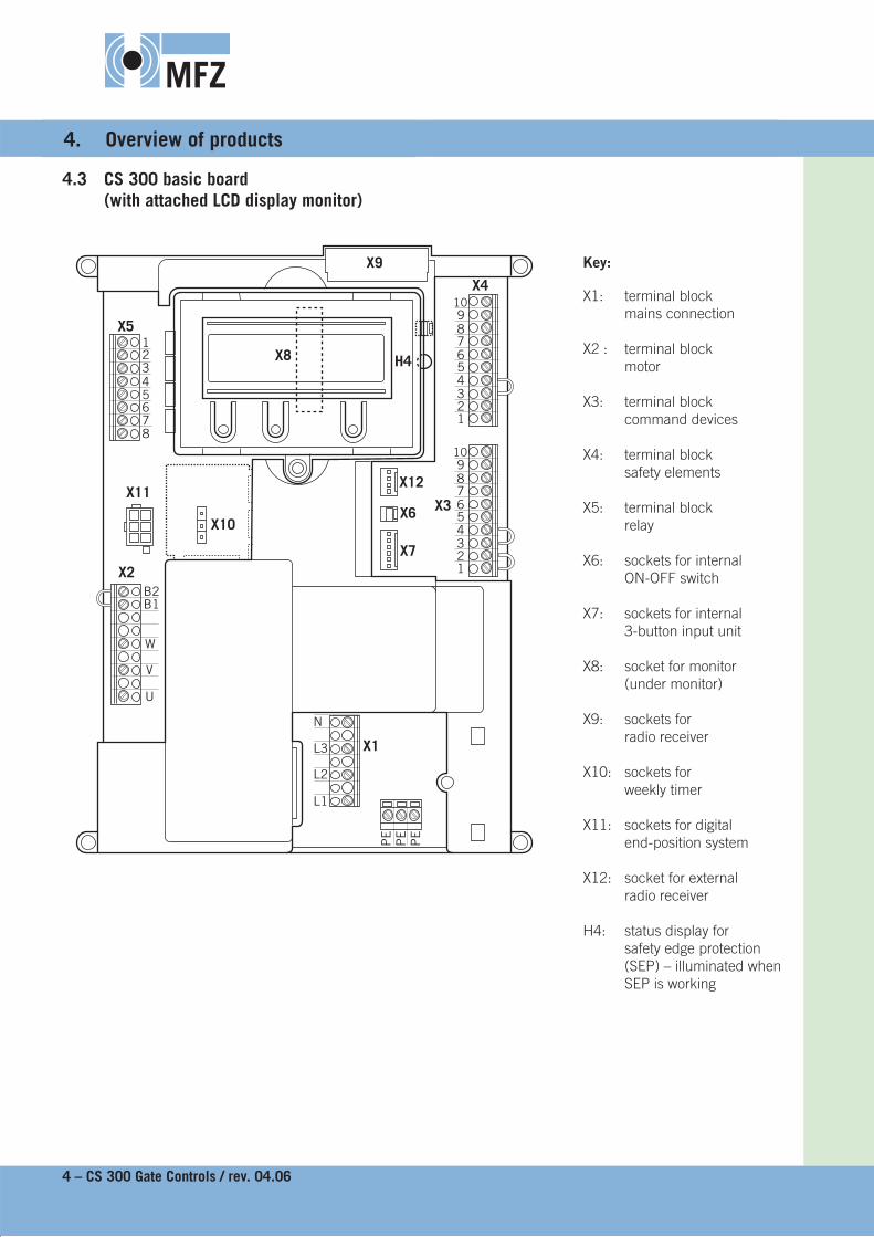
4.3 CS 300 basic board 4.3 CS 300 basic board (with attached LCD display monitor)(with attached LCD display monitor)
12345678
B2B1
W
V
U
123456789
10
N
L3
L2
L1
X5
X4
X3
X2
X11
X7
X6
X12
PE
PE
PE
X1
X10
123456789
10
X8
X9
H4
Key:
X1: terminal block mains connection
X2 : terminal block motor
X3: terminal block command devices
X4: terminal block safety elements
X5: terminal block relay
X6: sockets for internal ON-OFF switch
X7: sockets for internal 3-button input unit
X8: socket for monitor (under monitor)
X9: sockets for radio receiver
X10: sockets for weekly timer
X11: sockets for digital end-position system
X12: socket for external radio receiver
H4: status display for safety edge protection (SEP) – illuminated when SEP is working

MFZ
GB
CS 300 Gate Controls / rev. 04.06 – 5
5. Initial Operation
5.1 General5.1 General
Warning! Warning! To guarantee that the equipment functions properly, the following points must be ensured:- The gate or door is installed and ope rational.- The MFZ drive motor is installed and ready for operation.- The command and safety devices are installed and ready for operation.- The control housing with the CS 300 control is installed.
Information:Information: For the installation of the gate/door, the MFZ drive motor and the command and safety devices, the relevant manufacturer’s instructions are to be adhered to.
5.2 Mains connection5.2 Mains connection
Danger! Danger! To guarantee that the controls function properly, the following points must be ensured:- The mains voltage must correspond to the voltage stated on the type plate.- For a three-phase current, a clockwise rotating fi eld is required.- For a permanent connection, an all-pole main switch must be used.- For a three-phase connection, only 3-way automatic circuit breakers (10A) may be used.
Detailed circuit diagram for mains connection and motor
UV
WB
1B
2
L1L2
L3N
PE
PE
PE
13
51
35
24
62
46
X2
X1
X11
T1
K2
K1
M
M1
Key:
K1: protection, CLOSE
K2: protection, OPEN
M1: motor
T1: transformer
X1: terminal block for mains connection
X2: terminal block for motor
X11: sockets for digital end position system with safety circuit (STOP CIRCUIT)
Connection:Connect the digital end-position system to the Connect the digital end-position system to the control.control.Connect the control to the mains.Connect the control to the mains.Connect the control to the motor.Connect the control to the motor.
☞
☞☞
GB

MFZ
6 – CS 300 Gate Controls / rev. 04.06
5. Initial Operation
5.3 Allocation of connections for command and safety devices
Command and safety devices can be connected to terminals X3, X4 and X5.
Terminal block X3
- CLOSE switch
- impulse switch1
- OPEN switch
- STOP switch
- Emergency off, slack rope switch, wicket door contact, draw-in protection
Terminal block X4(for optoelectronic safety edge protection)
- PART – OPEN2
- safety edge protection OPTO
- photoelectric drive-through barrier3
- 24 V DC / 500 mA4
1 sequence control2 button or selector switch3 effective in down direction4 for external switching devices
(connection to terminals 1 and 2)
wt: whitegr: green br: brown
Terminal block X4(for 8.2 kOhm safety edge protection)
- PART - OPEN2
- safety edge protection
- photoelectric drive-through barrier3
- 24 V DC / 500 mA4
Terminal block X4(for pneumatic safety edge protection – pressure sensor test:- A 8.2 kOhm resistor must be connected in series- The input point pressure sensor TEST must be
switched on)
- PART - OPEN2
- safety edge protection
- photoelectric drive-through barrier3
- 24 V DC / 500 mA4
Terminal block X5(potential free switch contact)
- relay 1
- relay 2
- relay 3
- relay 4
12345678
123456789
10
123456789
10
+-
wtgrbr
0 V
Signal
+12 V
123456789
10
+-
8,2 KOhm
123456789
10
+-
8,2 KOhm

MFZ
GB
CS 300 Gate Controls / rev. 04.06 – 7
Impulse button(sequence control)
- impulse button
Connection:Connect the command and safety devices to the Connect the command and safety devices to the control.control.
☞
5.4 Connection examples for command and safety devices (terminal block X3)
OPEN / STOP / CLOSE buttons(6-lead solution)
- CLOSE button
- OPEN button
- STOP button
OPEN / STOP / CLOSE buttons(4-lead solution)
- CLOSE button
- OPEN button- STOP button
Key switch OPEN / CLOSE
- CLOSE
- OPEN
123456789
10
123456789
10
123456789
10
123456789
10

MFZ
8 – CS 300 Gate Controls / rev. 04.06
6.1 Overview of LED module6.1 Overview of LED module
Key:
LED off
LED illuminated
LED fl ashing
6. Programming with the LED module
6.2 LED module, modes of operation6.2 LED module, modes of operation
With the LED module, the controls have two modes of operation:1. AUTOMATIC2. ADJUSTMENT
Information:Information:The current mode of operation of the control is shown via the LEDs.- In the AUTOMATIC mode, no LEDs fl ash.- In the ADJUSTMENT mode, at least one LED fl ashes.Pressing the P button toggles between the modes of operation.
Operating mode 1: AUTOMATICIn the AUTOMATIC operating mode the door system is operated.
LED displays:
H1 H2 Status
The door is open. The programmed OPEN end position has been reached.
The door is closed. The programmed CLOSED end position has been reached.
The door is between end positions. No end position has been reached.
The door has been moved beyond the CLOSED/OPEN end position.

MFZ
GB
CS 300 Gate Controls / rev. 04.06 - 9
Operating mode 2: ADJUSTMENTIn the ADJUSTMENT mode, the OPEN/CLOSED end position settings are adjusted.
Warning!Warning!In the ADJUSTMENT mode of operation, the drive does not switch off when the end position is reached. The door can be damaged if driven beyond the end position.
LED displays:
H1 H2 Status
The OPEN end position is programmed at this door position.
The CLOSED end position is programmed at this door position.
The CLOSED and OPEN end positions are not programmed at this door position.
6.3 Setting the end positions6.3 Setting the end positions
Setting the OPEN end position
Change the mode of operation to ADJUSTMENT by pressing the P button.Change the mode of operation to ADJUSTMENT by pressing the P button.Drive the door into the desired OPEN end position by pressing the + button.Drive the door into the desired OPEN end position by pressing the + button.Save the end position by pressing simultaneously the P button and the + button.Save the end position by pressing simultaneously the P button and the + button.
Setting the CLOSED end position
Change the mode of operation to ADJUSTMENT by pressing the P button.Change the mode of operation to ADJUSTMENT by pressing the P button.Drive the door into the desired CLOSED end position by pressing the - button.Drive the door into the desired CLOSED end position by pressing the - button.Save the end position by pressing simultaneously the P button and the - button.
☞☞☞
☞☞☞

MFZ
10 – CS 300 Gate Controls / rev. 04.06
7.1 Overview of the LCD monitor7.1 Overview of the LCD monitor
7. Programming with the LCD monitor
A
B
C D E
F
GAUTOMATIC O
RESTING
Key:
A: mode of operation / diagnostic info
B: parameter / diagnostic info
C: + button
D: - button
E: P button
F: value / status
G: value / status
H: jumper
H

MFZ
GB
CS 300 Gate Controls / rev. 04.06 – 11
7.2 LCD monitor, modes of operation7.2 LCD monitor, modes of operation
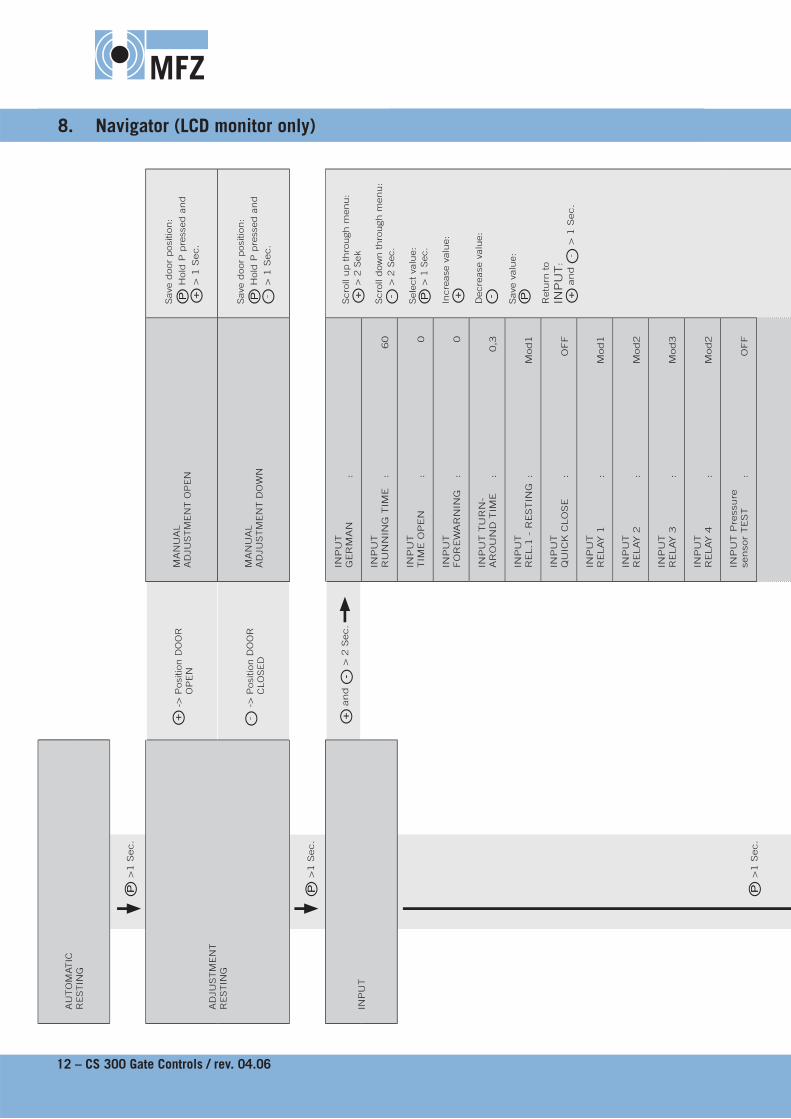
The control has four modes of operation with the LCD monitor:1. AUTOMATIC2. ADJUSTMENT3. INPUT4. DIAGNOSIS
When the jumper H is pulled, the + button, the - button and the P button have no function.The display still functions.
Operating mode 1: AUTOMATICIn the AUTOMATIC operating mode the door system is operated.
Display:- displays the function being carried out- displays any error messages
If the “self locking“ parameter is set to OFF in the input menu, the display changes from AUTOMATIC to MANUAL OPERATION.
Operating mode 2: ADJUSTMENTIn the ADJUSTMENT mode, the OPEN/CLOSED end position settings are adjusted.
Warning! Warning! In the ADJUSTMENT mode of operation, the drive does not switch off when the end position is reached. The door can be damaged if driven beyond the end position.
Fine adjustments can be made in the INPUT operating mode.
Display:- displays the end position value
Operating mode 3: INPUTIn the INPUT operating mode, the values of various parameters can be altered.
Display:- displays the selected parameter- displays the programmed value /status
Operating mode 4: DIAGNOSISIn the DIAGNOSIS operating mode, door-specifi c checks can be queried.
Display- displays the check- displays the checking status
MFZ
12 – CS 300 Gate Controls / rev. 04.06
AU
TO
MATIC
R
ESTIN
G
P
>1 S
ec.
AD
JUSTM
EN
TR
ESTIN
G
+ -
> P
osi
tion D
OO
R
OP
EN
MA
NU
AL
AD
JUSTM
EN
T O
PEN
Save
door
posi
tion:
P H
old
P p
ress
ed a
nd
+ >
1 S
ec.
- -
> P
osi
tion D
OO
R
CLO
SED
MA
NU
AL
AD
JUSTM
EN
T D
OW
N
Save
door
posi
tion:
P H
old
P p
ress
ed a
nd
- >
1 S
ec.
P
>1 S
ec.
INP
UT
+ a
nd
- >
2 S
ec.
INP
UT
GER
MA
N
: Scro
ll up thro
ugh m
enu:
+ >
2 S
ek
Scro
ll dow
n thro
ugh m
enu:
- >
2 S
ec.
Sele
ct va
lue:
P >
1 S
ec.
Incre
ase
valu
e:
+
Decre
ase
valu
e:
-
Save
valu
e:
P
Retu
rn to
INP
UT
:+
and
- >
1 S
ec.
INP
UT
RU
NN
ING
TIM
E
: 60
P
>1 S
ec.
INP
UT
TIM
E O
PEN
:
0
INP
UT
FO
REW
AR
NIN
G
: 0
INP
UT T
UR
N-
AR
OU
ND
TIM
E
: 0,3
INP
UT
REL.1
- R
ESTIN
G :
Mod1
INP
UT
QU
ICK
CLO
SE
: O
FF
INP
UT
RELAY 1
:
Mod1
INP
UT
RELAY 2
:
Mod2
INP
UT
RELAY 3
:
Mod3
INP
UT
RELAY 4
:
Mod2
INP
UT P
ress
ure
senso
r TEST
: O
FF
8. Navigator (LCD monitor only)

MFZ
GB
CS 300 Gate Controls / rev. 04.06 - 13
INP
UT
DELAY-O
PEN
:
OFF
INP
UT
FIN
E-O
PEN
:
4050
INP
UT
FIN
E-C
LO
SE
: 3950
INP
UT
BES-O
PEN
:
4000
INP
UT
BES-C
LO
SE
: 4000
INP
UT
RO
T. FIE
LD
:
RE
INP
UT
REVER
SE O
FF
: 50
INP
UT
PO
WER
:
0
INP
UT
AU
TO
LEVEL
: O
FF
INP
UT
SELF L
OC
K
: O
N
INP
UT
SU
/WI
: M
OD
1
DIA
GN
OSIS
Scro
ll up thro
ugh m
enu:
+ >
2 S
ek
Scro
ll dow
n thro
ugh m
enu:
- >
2 S
ec.
Retu
rn to A
UTO
MATIC
opera
ting m
ode:
P
Only
query
is
poss
ible
ES U
P
: O
NES D
OW
N
: O
N
OP
EN
BU
TTO
N
: O
FF
PA
RT O
PEN
:
OFF
CLO
SE B
UTTO
N
: O
FF
SEP
:
ON
IMP
ULS
: O
FF
TIM
ER
:
OFF
P/E
BA
RR
IER
:
ON
STO
P C
IRC
UIT
:
ON
CYC
LE
: 4
AVE
: 2599

MFZ
14 – CS 300 Gate Controls / rev. 04.06
9. Overview of functions
9.1 Automatic operating mode
Display Description
AUTOMATIC OPEN
The door is driven to the OPEN* end position
AUTOMATIC CLOSE
The door is driven to the CLOSED* end position
AUTOMATICRESTING
The door stands between the end positions
AUTOMATIC ORESTING
The door stands at the OPEN end position
AUTOMATIC oRESTING
The door stands at the position PART OPEN („before-end position“ up)
AUTOMATIC URESTING
The door stands at the CLOSED end position
AUTOMATIC uRESTING
The door stands at the position PART CLOSE („before-end position“ down)
AUTOMATIC rRESTING
The door stands in the position where the reversing switches off
*When the gate is being driven OPEN, the power currently being used is displayed
MFZ
GB
CS 300 Gate Controls / rev. 04.06 - 15
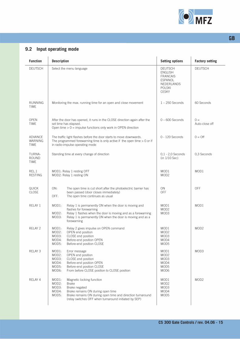
9.2 Input operating mode9.2 Input operating mode
Function Description Setting options Factory setting
DEUTSCH Select the menu language DEUTSCHENGLISHFRANCAISESPANOLNEDERLANDSPOLSKICESKY
DEUTSCH
RUNNING TIME
Monitoring the max. running time for an open and close movement 1 – 250 Seconds 60 Seconds
OPENTIME
After the door has opened, it runs in the CLOSE direction again after the set time has elapsed. Open time > 0 = impulse functions only work in OPEN direction
0 – 600 Seconds 0 = Auto-close off
ADVANCE WARNING TIME
The traffi c light fl ashes before the door starts to move downwards. The programmed forewarning time is only active if the open time > 0 or if in radio-impulse operating mode
0 - 120 Seconds 0 = Off
TURNA-ROUND TIME
Standing time at every change of direction 0,1 - 2,0 Seconds (in 1/10 Sec)
0,3 Seconds
REL.1RESTING
MOD1: Relay 1 resting OFFMOD2: Relay 1 resting ON
MOD1MOD2
MOD1
QUICK CLOSE
ON: The open time is cut short after the photoelectric barrier has been passed (door closes immediately)
OFF: The open time continues as usual
ONOFF
OFF
RELAY 1 MOD1: Relay 1 is permanently ON when the door is moving and fl ashes for forewarning
MOD2: Relay 1 fl ashes when the door is moving and as a forewarningMOD3: Relay 1 is permanently ON when the door is moving and as a
forewarning
MOD1MOD2MOD3
MOD1
RELAY 2 MOD1: Relay 2 gives impulse on OPEN commandMOD2: OPEN end position MOD3: CLOSE end position MOD4: Before-end position OPENMOD5: Before-end position CLOSE
MOD1MOD2MOD3MOD4MOD5
MOD2
RELAY 3 MOD1: Error messageMOD2: OPEN end position MOD3: CLOSE end position MOD4: Before-end position OPENMOD5: Before-end position CLOSEMOD6: From before CLOSE position to CLOSE position
MOD1MOD2MOD3MOD4MOD5MOD6
MOD3
RELAY 4 MOD1: Magnetic locking functionMOD2: BrakeMOD3: Brake negatedMOD4: Brake remains ON during open time MOD5: Brake remains ON during open time and direction turnaround
(relay switches OFF when turnaround initiated by SEP)
MOD1MOD2MOD3MOD4MOD5
MOD2

MFZ
16 – CS 300 Gate Controls / rev. 04.06
Function Description Setting options Factory setting
Pressure sensor TEST
ON: PS testing is activeOFF: PS testing is inactive
The testing of the PS switch takes place in the CLOSE end position. For this, the PS contact must be temporarily broken when the gate lowers to rest on the ground.
ONOFF
OFF
DELAY-OPEN
ON: Forewarning before openingOFF: Immediate opening
ONOFF
OFF
FINE-OPEN
Fine adjustment of OPEN end position 0 – 8190 4050
FINE-CLOSE
Fine adjustment of CLOSE end position 0 – 8190 3950
BES-OPEN Setting the before-end position switch point for the OPEN direction (PART-OPEN)
0 – 8190 4000
BES-CLOSE
Setting the before-end position switch point for the CLOSE direction 0 – 8190 4000
ROT. FIELD
C: clockwise rotating fi eldA: anti-clockwise rotating fi eld
This setting may only be altered in the case of a special customised drive installation!
RELI
RE
REVERSE OFF
The point where the reversing switch is activated before the CLOSE end position is reached.
10 – 250 50
POWER The power is displayed during the opening movement.If the power monitoring facility is activated, a value must be set, which is lower than the lowest value displayed during opening. The larger the difference, in comparison to the lowest value displayed, the less sensitive the reaction of the power monitoring. The power monitoring facility is only activated if the value is set to be > 0.
0 – 999 0
AUTO-LEVEL
ON: Align with ground, ONOFF: Align with ground, OFF
ONOFF
OFF
SELF LOCK.
ON: Automatic operationOFF: Manual operation
ONOFF
ON
SU/WI MOD1: PART-OPEN button at terminal X4 (9 + 10)MOD2: PART-OPEN selector switch at terminal X4 (9 + 10) When the selector switch is closed, all OPEN commands go to
the before-end switch OPEN
MOD1MOD2
MOD1
MFZ
GB
CS 300 Gate Controls / rev. 04.06 - 17
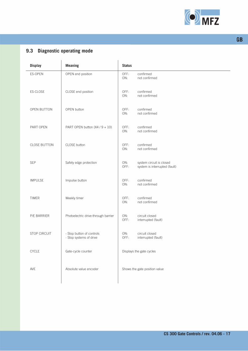
9.3 Diagnostic operating mode
Display Meaning Status
ES-OPEN OPEN end position OFF: confi rmedON: not confi rmed
ES-CLOSE CLOSE end position OFF: confi rmedON: not confi rmed
OPEN BUTTON OPEN button OFF: confi rmedON: not confi rmed
PART OPEN PART OPEN button (X4 / 9 + 10) OFF: confi rmedON: not confi rmed
CLOSE BUTTON CLOSE button OFF: confi rmedON: not confi rmed
SEP Safety edge protection ON: system circuit is closedOFF: system is interrupted (fault)
IMPULSE Impulse button OFF: confi rmedON: not confi rmed
TIMER Weekly timer OFF: confi rmedON: not confi rmed
P/E BARRIER Photoelectric drive-through barrier ON: circuit closedOFF: interrupted (fault)
STOP CIRCUIT - Stop button of controls- Stop systems of drive
ON: circuit closedOFF: interrupted (fault)
CYCLE Gate-cycle counter Displays the gate cycles
AVE Absolute value encoder Shows the gate position value

MFZ
18 – CS 300 Gate Controls / rev. 04.06
10. Error messages and rectifi cation
Fault / error message Cause Rectifi cation
System does not respond - No voltage supply - Check the voltage supply of the drive and the controls
Door travels to the CLOSE end position when the OPEN button is pressedDoor travels to the OPEN end position when the CLOSE button is pressed
- Rotating fi eld is connected wrongly - Check the rotating fi eld and establish clockwise rotating fi eld if necessary
ERROR END POSITION - The door has travelled beyond one of the end positions
- The end positions have not been programmed yet
- Check the programming of the end positions and reset them if necessary
ERROR RUN TIME - The programmed running time has been exceeded
- Check the path of the door- Re-programme the running time
ERROR SEP - The safety edge protection is faulty - Check the safety edge protection and the spiral cable
- Safety edge protection was triggered - Remove obstruction from path of door
ERROR PRESSURE SENSOR TESTING - The PS switch is not activated at the CLOSE end position
- Check the PS switch, spiral cable and profi le
- Check the setting for the CLOSE end position
ERROR ROT. FIELD - An incorrect rotating fi eld is connected to terminal X1
- Ensure that a clockwise rotating fi eld is connected
ERROR RS 485 - Communications fault between the end position switch and the controls
- Check the cable and socket connections
ERROR POWER - The power monitoring has been triggered
- Check that the door can move freely- Reset the power value
After rectifying the cause of the fault, the controls must be disconnected briefl y from the mains!

MFZ
GB
CS 300 Gate Controls / rev. 04.06 – 19
Model CS 300
Voltage 400 / 230 V
Frequency 50 Hz
Current 10 A max.
Protection grade IP 65
Operating temperature
-10˚ C to +60˚ C
Protection class I
Control voltage 24 V DC
Dimensions 215 mm x 275 mm x 190 mm
Weight 1,8 kg
Manufacturer:MFZ Antriebe GmbH & Co. Kg, Neue Muehle 4, 48739 Legden, Germany
We hereby declare that, by virtue of their conceptual development and design, as well as their manufacture as we have brought them onto the market, the products cited below:CS300 Door Controls conform to the relevant basic health and safety regulations of the following EU guidelines and standards:
EU Construction Products Directive 89/106/EUDIN EN 13241-1 DIN EN 12453DIN EN 12445DIN EN 12978
EU Electromagnetic Compatibility Directive 89/336/EUEN 50081-1EN 50082-1EN 55014-1EN 61000-3-2EN 61000-3-3
EU Machinery Directive 98/37/EUEN 60204-1EN 292-1
EU Low Voltage Directive 73/23/EUEN 60335-1EN 60335-2-103
BGR 232 - Directive for Power-driven Windows, Doors and Gates Directive for Power-driven Windows, Doors and Gates
Legden, 1 February 2006Manufacturer‘s signature:
Hans-Joachim Molterer
Position of signatory:Manager
11. Technical data 12. EU Declaration of Conformity

MFZ


