23
CS 457 – Lecture 19 Global Internet - BGP Fall 2011

CS 457 – Lecture 19 Global Internet - BGP
Fall 2011

Decision Process
• Calculate degree of preference for each route in Adj-RIB-In as follows (apply following steps until one route is left): – select route with highest LOCAL-PREF – select route with shortest AS-PATH – apply MED (if routes learned from same
neighbor) – select route with smallest NEXT-HOP cost

...Decision Process
– select route learned from E-BGP peer with lowest BGP ID
– select route from I-BGP neighbor with lowest BGP ID
• Install selected route in Loc-RIB • Selectively disseminate routes to peers,
update Adj-RIB-Out • Done
Multi-homing
• With multi-homing, a single network has more than one connections to the Internet
• Improves reliability and performance: – can accommodate link failure – bandwidth is sum of links to Internet
• Multiple connections provide load sharing but not load balancing – BGP cannot do load balancing

Issues With Multi-homing
• Symmetric routing – while conventional wisdom prefers
symmetric paths, many (most?) are asymmetric
• Packet re-ordering – may trigger TCP’s fast retransmit algorithm
• Other concerns: – addressing, DNS, aggregation

Static Routing May Not Work
ISP1
Customer
R1 R2
ISP2
ISP3
ISPn
Static routing may send traffic from ISPs 2-n to customer over one link and traffic from ISP1 over the other link. Lacks flexibility.
Inter- connect
Static route from R1 to customer over L1 Static route from R2 to customer over L2
L1 L2
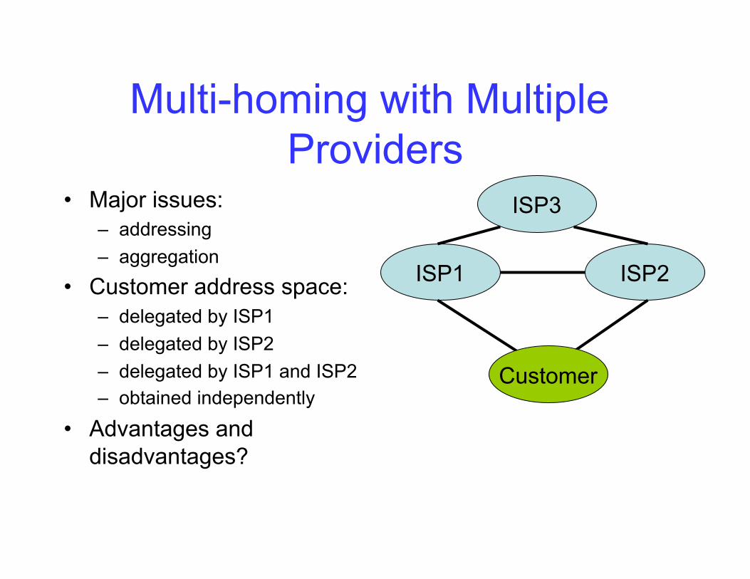
Multi-homing with Multiple Providers
• Major issues: – addressing – aggregation
• Customer address space: – delegated by ISP1 – delegated by ISP2 – delegated by ISP1 and ISP2 – obtained independently
• Advantages and disadvantages?
ISP1 ISP2
ISP3
Customer
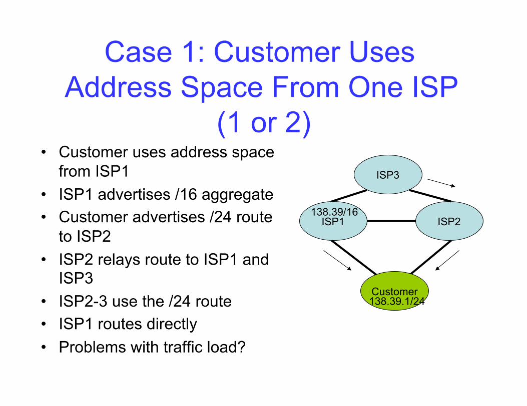
Case 1: Customer Uses Address Space From One ISP
(1 or 2) • Customer uses address space
from ISP1 • ISP1 advertises /16 aggregate • Customer advertises /24 route
to ISP2 • ISP2 relays route to ISP1 and
ISP3 • ISP2-3 use the /24 route • ISP1 routes directly • Problems with traffic load?
ISP1 ISP2
ISP3
Customer
138.39/16
138.39.1/24
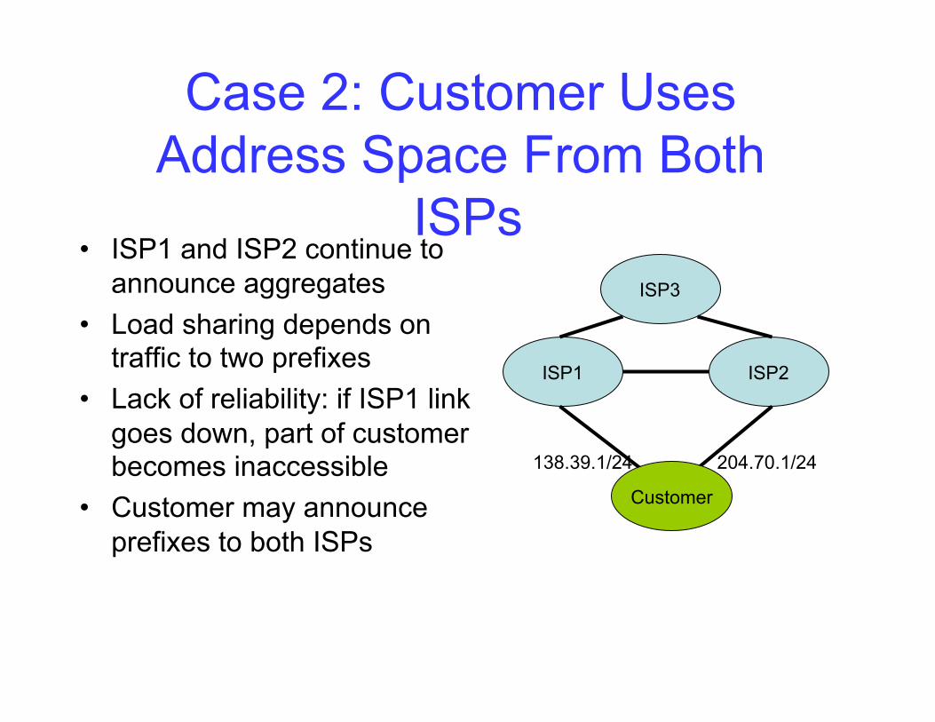
Case 2: Customer Uses Address Space From Both
ISPs • ISP1 and ISP2 continue to
announce aggregates • Load sharing depends on
traffic to two prefixes • Lack of reliability: if ISP1 link
goes down, part of customer becomes inaccessible
• Customer may announce prefixes to both ISPs
ISP1 ISP2
ISP3
Customer
138.39.1/24 204.70.1/24

Case 3: Customer Uses Its Own Address Space
• Offers the most control, but at the cost of aggregation
• Still need to control paths: – suppose ISP1 large,
ISP2-3 small – want traffic directly from ISP1, but ISP3 should send via ISP2
– customer advertises artificially long path to ISP1, but local-pref attribute at ISP overrides
– ISP3 learns shorter path from ISP2
ISP1 ISP2
ISP3
Customer
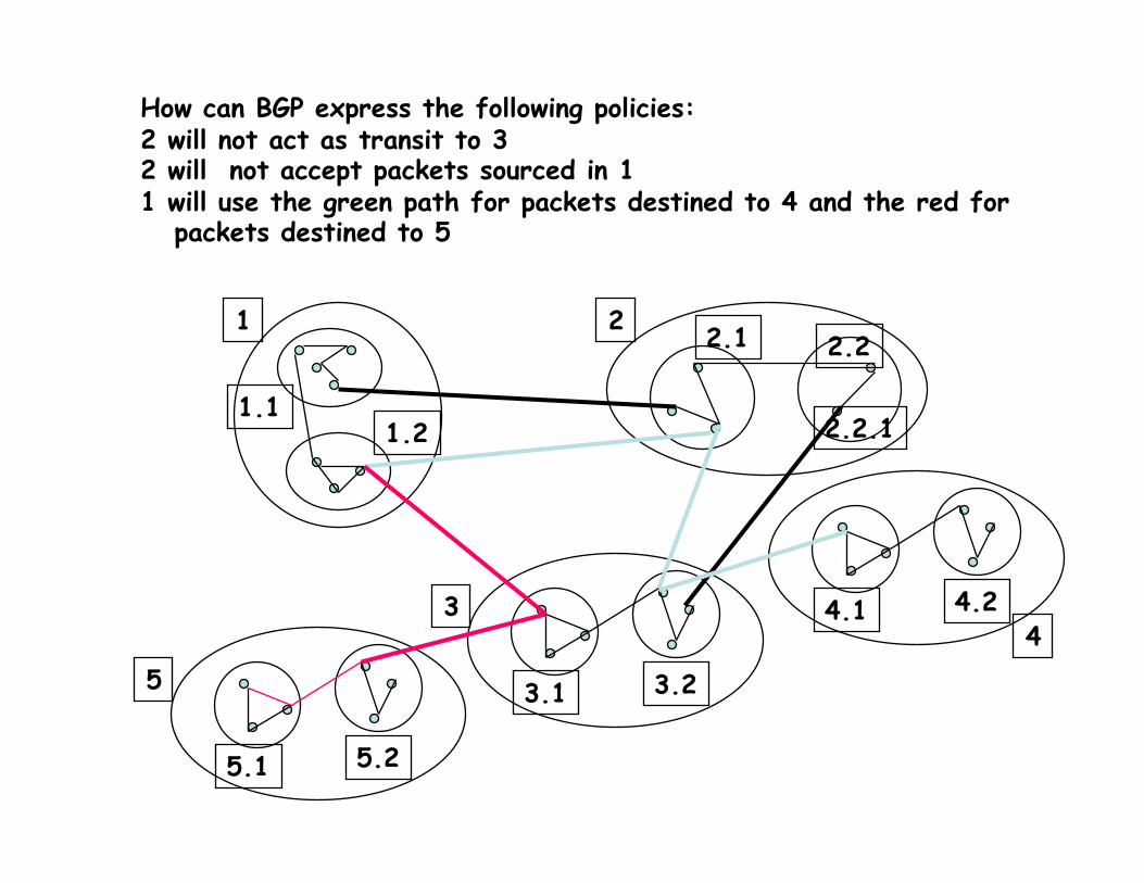
1 2
3
1.1 1.2
2.1 2.2
3.1 3.2
2.2.1
How can BGP express the following policies: 2 will not act as transit to 3 2 will not accept packets sourced in 1 1 will use the green path for packets destined to 4 and the red for packets destined to 5
4 4.1 4.2
5
5.1 5.2
IPv6 • Initial motivation: 32-bit address space
soon to be completely allocated. • Additional motivation:
– header format helps speed processing/forwarding
– header changes to facilitate QoS IPv6 datagram format: – fixed-length 40 byte header – no fragmentation allowed
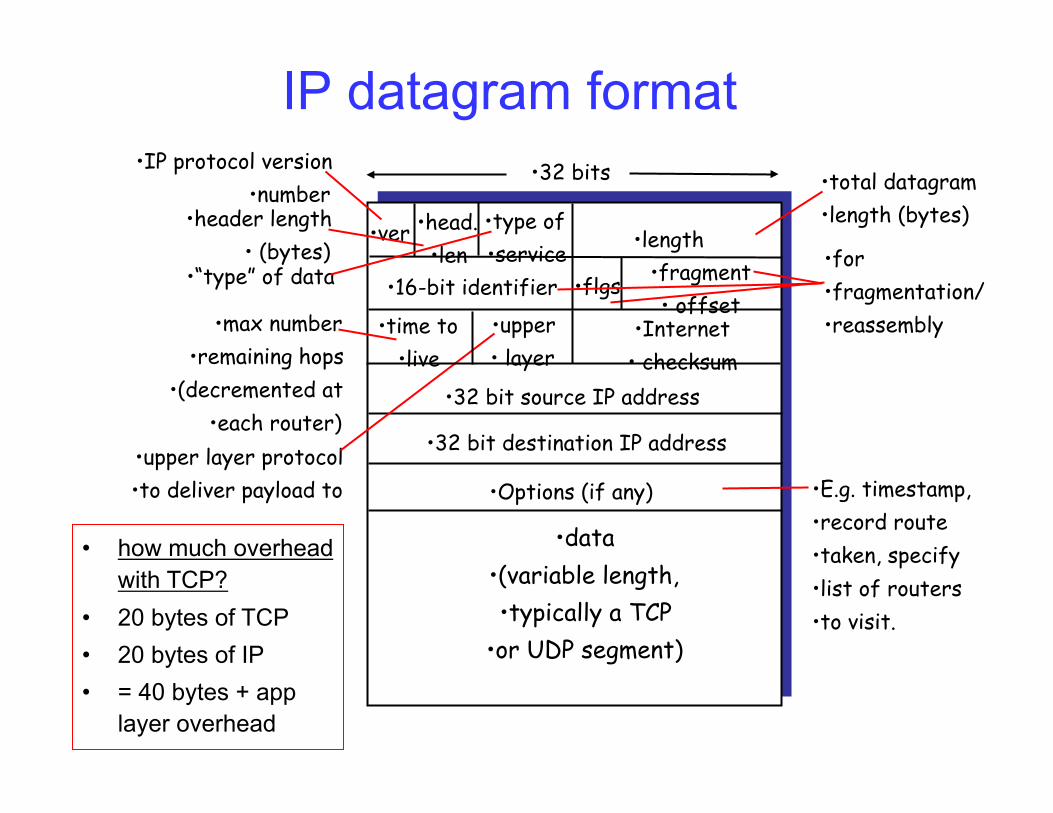
IP datagram format
• ver • length
• 32 bits
• data • (variable length, • typically a TCP
• or UDP segment)
• 16-bit identifier
• Internet • checksum
• time to • live
• 32 bit source IP address
• IP protocol version • number
• header length • (bytes)
• max number • remaining hops
• (decremented at • each router)
• for • fragmentation/ • reassembly
• total datagram • length (bytes)
• upper layer protocol • to deliver payload to
• head. • len
• type of • service
• “type” of data • flgs • fragment • offset
• upper • layer
• 32 bit destination IP address
• Options (if any) • E.g. timestamp, • record route • taken, specify • list of routers • to visit.
• how much overhead with TCP?
• 20 bytes of TCP • 20 bytes of IP • = 40 bytes + app
layer overhead
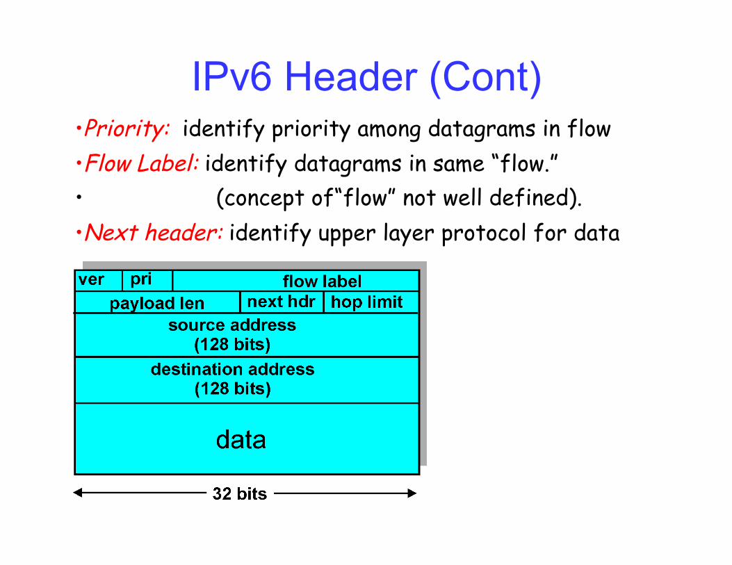
IPv6 Header (Cont) • Priority: identify priority among datagrams in flow • Flow Label: identify datagrams in same “flow.” • (concept of“flow” not well defined). • Next header: identify upper layer protocol for data

Other Changes from IPv4
• Checksum: removed entirely to reduce processing time at each hop
• Options: allowed, but outside of header, indicated by “Next Header” field
• ICMPv6: new version of ICMP – additional message types, e.g. “Packet Too
Big” – multicast group management functions

Transition From IPv4 To IPv6 • Not all routers can be upgraded
simultaneous – no “flag days” – How will the network operate with mixed IPv4
and IPv6 routers? • Tunneling: IPv6 carried as payload in IPv4
datagram among IPv4 routers
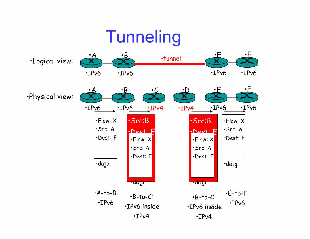
Tunneling • A • B • E • F
• IPv6 • IPv6 • IPv6 • IPv6
• tunnel • Logical view:
• Physical view: • A • B • E • F
• IPv6 • IPv6 • IPv6 • IPv6
• C • D
• IPv4 • IPv4
• Flow: X • Src: A • Dest: F
• data
• Flow: X • Src: A • Dest: F
• data
• Flow: X • Src: A • Dest: F
• data
• Src:B • Dest: E
• Flow: X • Src: A • Dest: F
• data
• Src:B • Dest: E
• A-to-B: • IPv6
• E-to-F: • IPv6
• B-to-C: • IPv6 inside
• IPv4
• B-to-C: • IPv6 inside
• IPv4

NAT: Network Address Translation
• Motivation: local network uses just one IP address as far as outside word is concerned: – no need to be allocated range of addresses from ISP: -
just one IP address is used for all devices – can change addresses of devices in local network
without notifying outside world – can change ISP without changing addresses of devices
in local network – devices inside local net not explicitly addressable, visible
by outside world (a security plus).
NAT: Network Address Translation
• 16-bit port-number field: – 60,000 simultaneous connections with a single LAN-side
address! • NAT is controversial (books term):
– NAT is evil (protocol designer and security term) – routers should only process up to layer 3 – violates end-to-end argument
• NAT possibility must be taken into account by app designers, eg, P2P applications
– address shortage should instead be solved by IPv6

NAT: Network Address Translation
10.0.0.1
10.0.0.2
10.0.0.3
10.0.0.4
138.76.29.7
local network (e.g., home network)
10.0.0/24
rest of Internet
Datagrams with source or destination in this network have 10.0.0/24 address for
source, destination (as usual)
All datagrams leaving local network have same single source
NAT IP address: 138.76.29.7, different source port numbers

NAT: Network Address Translation
Implementation: NAT router must:
– outgoing datagrams: replace (source IP address, port #) of every outgoing datagram to (NAT IP address, new port #) . . . remote clients/servers will respond using (NAT IP
address, new port #) as destination addr.
– remember (in NAT translation table) every (source IP address, port #) to (NAT IP address, new port #) translation pair
– incoming datagrams: replace (NAT IP address, new port #) in dest fields of every incoming datagram with corresponding (source IP address, port #) stored in NAT table
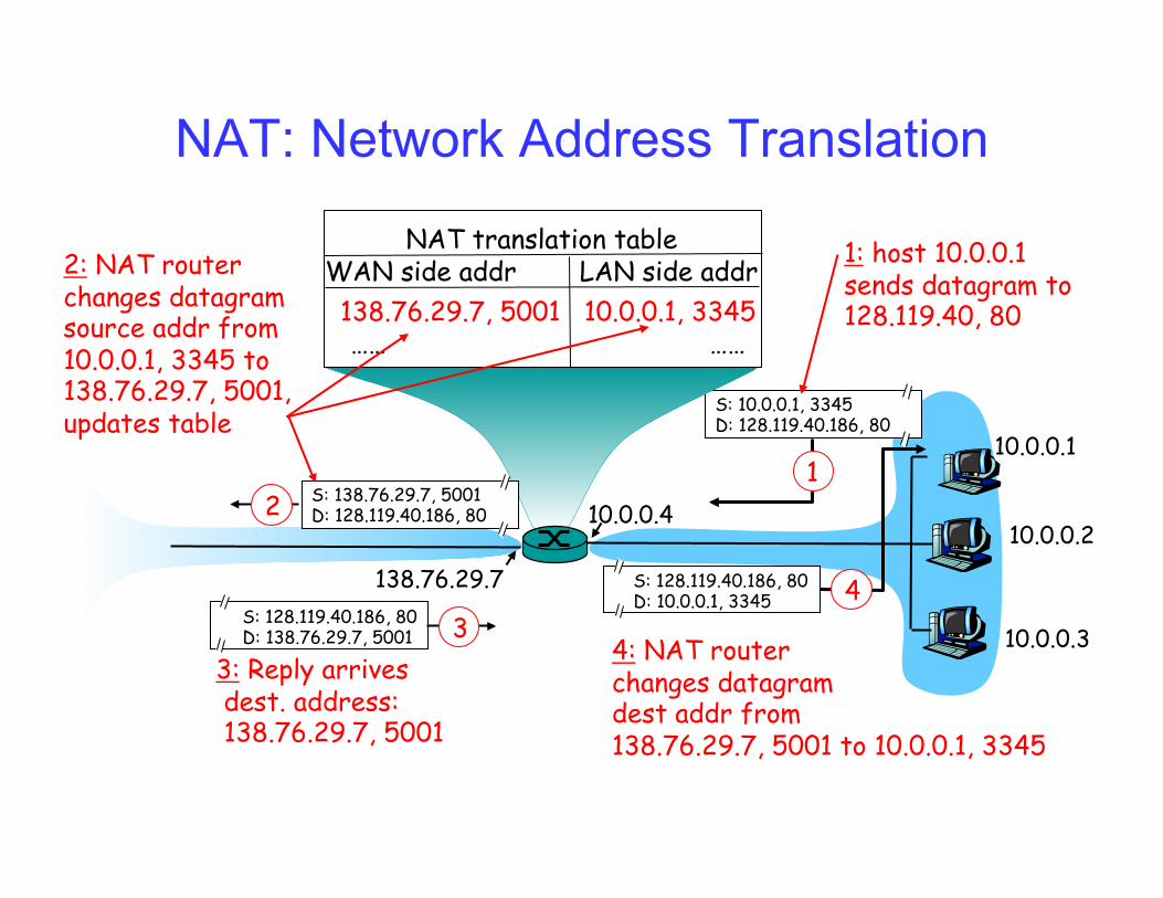
NAT: Network Address Translation
10.0.0.1
10.0.0.2
10.0.0.3
S: 10.0.0.1, 3345 D: 128.119.40.186, 80
1 10.0.0.4
138.76.29.7
1: host 10.0.0.1 sends datagram to 128.119.40, 80
NAT translation table WAN side addr LAN side addr 138.76.29.7, 5001 10.0.0.1, 3345 …… ……
S: 128.119.40.186, 80 D: 10.0.0.1, 3345 4
S: 138.76.29.7, 5001 D: 128.119.40.186, 80 2
2: NAT router changes datagram source addr from 10.0.0.1, 3345 to 138.76.29.7, 5001, updates table
S: 128.119.40.186, 80 D: 138.76.29.7, 5001 3
3: Reply arrives dest. address: 138.76.29.7, 5001
4: NAT router changes datagram dest addr from 138.76.29.7, 5001 to 10.0.0.1, 3345

What’s Next • Read Chapter 1, 2, 3, and 4.1-4.3 • Next Lecture Topics from Chapter 5.1 and 5.2
– UDP and TCP
• Homework – Due Thursday in lecture
• Project 3 – Will be posted this week


