Page 1
10/05/01 ©UCB Fall 2001 CS152 / Kubiatowicz
Lec11.1
CS 152 Computer Architecture and Engineering
Lecture 11
Multicycle Controller Design
October 5, 2001
John Kubiatowicz (http.cs.berkeley.edu/~kubitron)
lecture slides: http://www-inst.eecs.berkeley.edu/~cs152/
Page 2
10/05/01 ©UCB Fall 2001 CS152 / Kubiatowicz
Lec11.2
Overview of Control
° Control may be designed using one of several initial representations. The choice of sequence control, and how logic is represented, can then be determined independently; the control can then be implemented with one of several methods using a structured logic technique.
Initial Representation Finite State Diagram Microprogram
Sequencing Control Explicit Next State Microprogram counter Function + Dispatch ROMs
Logic Representation Logic Equations Truth Tables
Implementation PLA ROM Technique
“hardwired control” “microprogrammed control”
Page 3
10/05/01 ©UCB Fall 2001 CS152 / Kubiatowicz
Lec11.3
Recap: “Macroinstruction” Interpretation
MainMemory
executionunit
controlmemory
CPU
ADDSUBAND
DATA
.
.
.
User program plus Data
this can change!
AND microsequence
e.g., Fetch Calc Operand Addr Fetch Operand(s) Calculate Save Answer(s)
one of these ismapped into oneof these
Page 4
10/05/01 ©UCB Fall 2001 CS152 / Kubiatowicz
Lec11.4
Recap: Micro-controller Design
° The state digrams that arise define the controller for an instruction set processor are highly structured
° Use this structure to construct a simple “microsequencer”
• Each state in previous diagram becomes a “microinstruction”
• Microinstructions often taken sequentially
° Control reduces to programming this device
sequencercontrol
datapath control
micro-PCsequencer
microinstruction ()
Page 5
10/05/01 ©UCB Fall 2001 CS152 / Kubiatowicz
Lec11.5
The Big Picture: Where are We Now?
° The Five Classic Components of a Computer
° Today’s Topics: • Microprogramed control
• Administrivia; Courses
• Microprogram it yourself
• Exceptions
• Intro to Pipelining (if time permits)
Control
Datapath
Memory
Processor
Input
Output
Page 6
10/05/01 ©UCB Fall 2001 CS152 / Kubiatowicz
Lec11.6
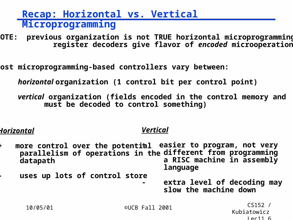
Recap: Horizontal vs. Vertical Microprogramming
NOTE: previous organization is not TRUE horizontal microprogramming; register decoders give flavor of encoded microoperations
Most microprogramming-based controllers vary between:
horizontal organization (1 control bit per control point)
vertical organization (fields encoded in the control memory and must be decoded to control something)
Horizontal
+ more control over the potential parallelism of operations in the datapath
- uses up lots of control store
Vertical
+ easier to program, not very different from programming a RISC machine in assembly language
- extra level of decoding may slow the machine down
Page 7
10/05/01 ©UCB Fall 2001 CS152 / Kubiatowicz
Lec11.7
Recap: Designing a Microinstruction Set
1) Start with list of control signals
2) Group signals together that make sense (vs. random): called “fields”
3) Places fields in some logical order (e.g., ALU operation & ALU operands first and microinstruction sequencing last)
4) Create a symbolic legend for the microinstruction format, showing name of field values and how they set the control signals
• Use computers to design computers
5) To minimize the width, encode operations that will never be used at the same time
Page 8
10/05/01 ©UCB Fall 2001 CS152 / Kubiatowicz
Lec11.8
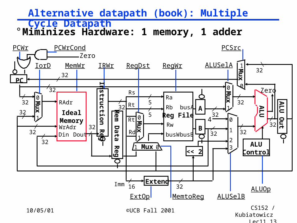
Alternative datapath (book): Multiple Cycle Datapath
° Miminizes Hardware: 1 memory, 1 adder
IdealMemoryWrAdrDin
RAdr
32
32
32Dout
MemWr
32
AL
U
3232
ALUOp
ALUControl
32
IRWr
Instru
ction R
eg
32
Reg File
Ra
Rw
busW
Rb5
5
32busA
32busB
RegWr
Rs
Rt
Mu
x
0
1
Rt
Rd
PCWr
ALUSelA
Mux 01
RegDst
Mu
x
0
1
32
PC
MemtoReg
Extend
ExtOp
Mu
x
0
132
0
1
23
4
16Imm 32
<< 2
ALUSelB
Mu
x1
0
32
Zero
ZeroPCWrCond PCSrc
32
IorD
Mem
Data R
eg
AL
U O
ut
B
A
Page 9
10/05/01 ©UCB Fall 2001 CS152 / Kubiatowicz
Lec11.9
1&2) Start with list of control signals, grouped into fields
Signal name Effect when deasserted Effect when assertedALUSelA 1st ALU operand = PC 1st ALU operand = Reg[rs]RegWrite None Reg. is written MemtoReg Reg. write data input = ALU Reg. write data input = memory RegDst Reg. dest. no. = rt Reg. dest. no. = rdMemRead None Memory at address is read,
MDR <= Mem[addr]MemWrite None Memory at address is written IorD Memory address = PC Memory address = SIRWrite None IR <= MemoryPCWrite None PC <= PCSourcePCWriteCond None IF ALUzero then PC <= PCSourcePCSource PCSource = ALU PCSource = ALUoutExtOp Zero Extended Sign Extended
Sin
gle
Bit
Con
trol
Signal name Value Effect ALUOp 00 ALU adds 01 ALU subtracts 10 ALU does function code
11 ALU does logical OR ALUSelB 00 2nd ALU input = 4 01 2nd ALU input = Reg[rt] 10 2nd ALU input = extended,shift left 2 11 2nd ALU input = extended
Mu
ltip
le B
it C
ontr
ol
Page 10
10/05/01 ©UCB Fall 2001 CS152 / Kubiatowicz
Lec11.10
4) Legend of Fields and Symbolic Names
Field Name Values for Field Function of Field with Specific ValueALU Add ALU adds
Subt. ALU subtractsFunc code ALU does function codeOr ALU does logical OR
SRC1 PC 1st ALU input = PCrs 1st ALU input = Reg[rs]
SRC2 4 2nd ALU input = 4Extend 2nd ALU input = sign ext. IR[15-0]Extend0 2nd ALU input = zero ext. IR[15-0] Extshft 2nd ALU input = sign ex., sl IR[15-0]rt 2nd ALU input = Reg[rt]
destination rd ALU Reg[rd] = ALUout rt ALU Reg[rt] = ALUout
rt Mem Reg[rt] = Mem Memory Read PC Read memory using PC
Read ALU Read memory using ALUout for addrWrite ALU Write memory using ALUout for addr
Memory register IR IR = MemPC write ALU PC = ALU
ALUoutCond IF ALU Zero then PC = ALUoutSequencing Seq Go to sequential µinstruction
Fetch Go to the first microinstructionDispatch Dispatch using ROM.
Page 11
10/05/01 ©UCB Fall 2001 CS152 / Kubiatowicz
Lec11.11
Quick check: what do these fieldnames mean?
Code Name RegWrite MemToRegRegDest
00 --- 0 X X01 rd ALU 1 0 110 rt ALU 1 0 011 rt MEM 1 1 0
Code Name ALUSelB ExtOp000 --- X X001 4 00 X010 rt 01 X011 ExtShft 10 1100 Extend 11 1111 Extend0 11 0
Destination:
SRC2:
Page 12
10/05/01 ©UCB Fall 2001 CS152 / Kubiatowicz
Lec11.12
3) Microinstruction Format: unencoded vs. encoded fields
Field Name Width Control Signals Set
wide narrow
ALU Control 4 2 ALUOp
SRC1 2 1 ALUSelA
SRC2 5 3 ALUSelB, ExtOp
ALU Destination 3 2 RegWrite, MemtoReg, RegDst
Memory 3 2 MemRead, MemWrite, IorD
Memory Register 1 1 IRWrite
PCWrite Control 3 2 PCWrite, PCWriteCond, PCSource
Sequencing 3 2 AddrCtl
Total width 24 15 bits
Page 13
10/05/01 ©UCB Fall 2001 CS152 / Kubiatowicz
Lec11.13
Alternative datapath (book): Multiple Cycle Datapath
° Miminizes Hardware: 1 memory, 1 adder
IdealMemoryWrAdrDin
RAdr
32
32
32Dout
MemWr
32
AL
U
3232
ALUOp
ALUControl
32
IRWr
Instru
ction R
eg
32
Reg File
Ra
Rw
busW
Rb5
5
32busA
32busB
RegWr
Rs
Rt
Mu
x
0
1
Rt
Rd
PCWr
ALUSelA
Mux 01
RegDst
Mu
x
0
1
32
PC
MemtoReg
Extend
ExtOp
Mu
x
0
132
0
1
23
4
16Imm 32
<< 2
ALUSelB
Mu
x1
0
32
Zero
ZeroPCWrCond PCSrc
32
IorD
Mem
Data R
eg
AL
U O
ut
B
A
Page 14
10/05/01 ©UCB Fall 2001 CS152 / Kubiatowicz
Lec11.14
Finite State Machine (FSM) Spec
IR <= MEM[PC]PC <= PC + 4
R-type
ALUout <= A fun B
R[rd] <= ALUout
ALUout <= A or ZX
R[rt] <= ALUout
ORi
ALUout <= A + SX
R[rt] <= M
M <= MEM[ALUout]
LW
ALUout <= A + SX
MEM[ALUout] <= B
SW
“instruction fetch”
“decode”
0000
0001
0100
0101
0110
0111
1000
1001
1010
1011
1100
BEQ
0010
If A = B then PC <= ALUout
ALUout <= PC +SX
Exe
cute
Mem
ory
Writ
e-ba
ck
Page 15
10/05/01 ©UCB Fall 2001 CS152 / Kubiatowicz
Lec11.15
Recap: Specific Sequencer from last lecture
°Sequencer-based control unit from last lecture• Called “microPC” or “µPC” vs. state register
Control Value Effect 00 Next µaddress = 0 01 Next µaddress = dispatch ROM 10 Next µaddress = µaddress + 1
ROM:
Opcode
microPC
1
µAddressSelectLogic
Adder
ROM
Mux
0012
R-type 000000 0100BEQ 000100 0011ori 001101 0110LW 100011 1000SW 101011 1011
Page 16
10/05/01 ©UCB Fall 2001 CS152 / Kubiatowicz
Lec11.16
Microprogram it yourself!
Label ALU SRC1 SRC2 ALU Dest. Memory Mem. Reg. PC Write Sequencing
Fetch: Add PC 4 Read PC IR ALU SeqAdd PC Extshft Dispatch
Rtype:Funct rs rt Seqrd ALU Fetch
BEQ: Subt rs rt ALUoutCond Fetch
Page 17
10/05/01 ©UCB Fall 2001 CS152 / Kubiatowicz
Lec11.17
Microprogram it yourself!
Label ALU SRC1 SRC2 Dest. Memory Mem. Reg. PC Write SequencingFetch: Add PC 4 Read PC IR ALU Seq
Add PC Extshft Dispatch
Rtype: Func rs rt Seqrd ALU Fetch
Ori: Or rs Extend0 Seqrt ALU Fetch
Lw: Add rs Extend SeqRead ALU Seq
rt MEM Fetch
Sw: Add rs Extend SeqWrite ALU Fetch
Beq: Subt. rs rt ALUoutCond. Fetch
Page 18
10/05/01 ©UCB Fall 2001 CS152 / Kubiatowicz
Lec11.18
Administrivia
° Midterm I next Wednesday• 5:30 - 8:30 in 277 Cory (Honest!)• Bring a Calculator!• One 8 1/2 by 11 page (both sides) of notes• Make up exam: 5:30 – 8:30 in 606 Soda Hall
° Materials through Chapter 5, Appendix A, B & C° Review session this Sunday 7:00 306 Soda° Afterwards: Pizza and refreshments at LaVals
° Lab 4 breakdown due by midnight tonight• EMail to your TA• Get moving on it! This is a complicated lab.
° Now, start reading Chapter 6
Page 19
10/05/01 ©UCB Fall 2001 CS152 / Kubiatowicz
Lec11.19
Administrivia: Courses to consider during Telebears
° General Philosophy• Take courses from great teachers (HKN ratings helps find them)
- http://www-hkn.eecs.berkeley.edu/toplevel/coursesurveys.html
• Take variety of undergrad courses now to get introduction to areas; can learn advanced material on own later once know vocabulary
• Who knows what you will work on over a 40 year career?
° CS169 Software Engineering• Everyone writes programs, even hardware designers
• Often programs are written in groups => learn skill in school
° EE122 Introduction to Communication Networks• World is getting connected; communications must play major role
° CS162 Operating Systems• All special-purpose hardware will run a layer of software that uses
processes and concurrent programming; CS162 is the closest thing
Page 20
10/05/01 ©UCB Fall 2001 CS152 / Kubiatowicz
Lec11.20
Lab4: start using test benches° Idea: wrap testing infrastructure around devices under
test (DUT)
° Include test vectors that are supposed to detect errors in implementation. Even strange ones…
° Can (and probably should in later labs) include assert statements to check for “things that should never happen”
Test Bench
Device UnderTest
Inline vectorsAssert StatementsFile IO (either for patternsor output diagnostics)
Inline Monitor
Output in readableformat (disassembly)Assert Statements
Complete Top-Level Design
Page 21
10/05/01 ©UCB Fall 2001 CS152 / Kubiatowicz
Lec11.21
An Alternative MultiCycle DataPath
° In each clock cycle, each Bus can be used to transfer from one source
° µ-instruction can simply contain B-Bus and W-Dst fields
RegFile
A
B
A-Bus
B Bus
IR S mem
W-Bus
PC
instmem
nextPC ZX SX
Page 22
10/05/01 ©UCB Fall 2001 CS152 / Kubiatowicz
Lec11.22
What about a 2-Bus Microarchitecture (datapath)?
RegFile
A
B
A-BusB Bus
IR SPC
nextPC ZXSX
Mem
RegFile
A
BIR SP
CnextPC ZXSX
Mem
Instruction Fetch
Decode / Operand Fetch
M
M
Page 23
10/05/01 ©UCB Fall 2001 CS152 / Kubiatowicz
Lec11.23
Load
° What about 1 bus ? 1 adder? 1 Register port?
RegFile
A
BIR SP
CnextPC ZXSX
Mem
RegFile
A
BIR SP
CnextPC ZXSX
Mem
RegFile
A
BIR SP
CnextPC ZXSX
Mem
Execute
addr
M
M
M
Mem
Write-back
Page 24
10/05/01 ©UCB Fall 2001 CS152 / Kubiatowicz
Lec11.24
Legacy Software and Microprogramming
° IBM bet company on 360 Instruction Set Architecture (ISA): single instruction set for many classes of machines
• (8-bit to 64-bit)
° Stewart Tucker stuck with job of what to do about software compatibility
• If microprogramming could easily do same instruction set on many different microarchitectures, then why couldn’t multiple microprograms do multiple instruction sets on the same microarchitecture?
• Coined term “emulation”: instruction set interpreter in microcode for non-native instruction set
• Very successful: in early years of IBM 360 it was hard to know whether old instruction set or new instruction set was more frequently used
Page 25
10/05/01 ©UCB Fall 2001 CS152 / Kubiatowicz
Lec11.25
Microprogramming Pros and Cons
° Ease of design
° Flexibility• Easy to adapt to changes in organization, timing, technology
• Can make changes late in design cycle, or even in the field
° Can implement very powerful instruction sets (just more control memory)
° Generality• Can implement multiple instruction sets on same machine.
• Can tailor instruction set to application.
° Compatibility• Many organizations, same instruction set
° Costly to implement
° Slow
Page 26
10/05/01 ©UCB Fall 2001 CS152 / Kubiatowicz
Lec11.26
Exceptions
° Exception = unprogrammed control transfer• system takes action to handle the exception
- must record the address of the offending instruction- record any other information necessary to return afterwards
• returns control to user• must save & restore user state
° Allows constuction of a “user virtual machine”
normal control flow: sequential, jumps, branches, calls, returns
user program SystemExceptionHandlerException:
return fromexception
Page 27
10/05/01 ©UCB Fall 2001 CS152 / Kubiatowicz
Lec11.27
Two Types of Exceptions: Interrupts and Traps° Interrupts
• caused by external events:
- Network, Keyboard, Disk I/O, Timer
• asynchronous to program execution
- Most interrupts can be disabled for brief periods of time
- Some (like “Power Failing”) are non-maskable (NMI)
• may be handled between instructions
• simply suspend and resume user program
° Traps• caused by internal events
- exceptional conditions (overflow)
- errors (parity)
- faults (non-resident page)
• synchronous to program execution
• condition must be remedied by the handler
• instruction may be retried or simulated and program continued or program may be aborted
Page 28
10/05/01 ©UCB Fall 2001 CS152 / Kubiatowicz
Lec11.28
MIPS convention:
° exception means any unexpected change in control flow, without distinguishing internal or external; use the term interrupt only when the event is externally caused.
Type of event From where? MIPS terminologyI/O device request External InterruptInvoke OS from user program Internal ExceptionArithmetic overflow Internal ExceptionUsing an undefined instruction Internal ExceptionHardware malfunctions Either Exception or
Interrupt
Page 29
10/05/01 ©UCB Fall 2001 CS152 / Kubiatowicz
Lec11.29
What happens to Instruction with Exception?
° MIPS architecture defines the instruction as having no effect if the instruction causes an exception.
° When get to virtual memory we will see that certain classes of exceptions must prevent the instruction from changing the machine state.
° This aspect of handling exceptions becomes complex and potentially limits performance => why it is hard
Page 30
10/05/01 ©UCB Fall 2001 CS152 / Kubiatowicz
Lec11.30
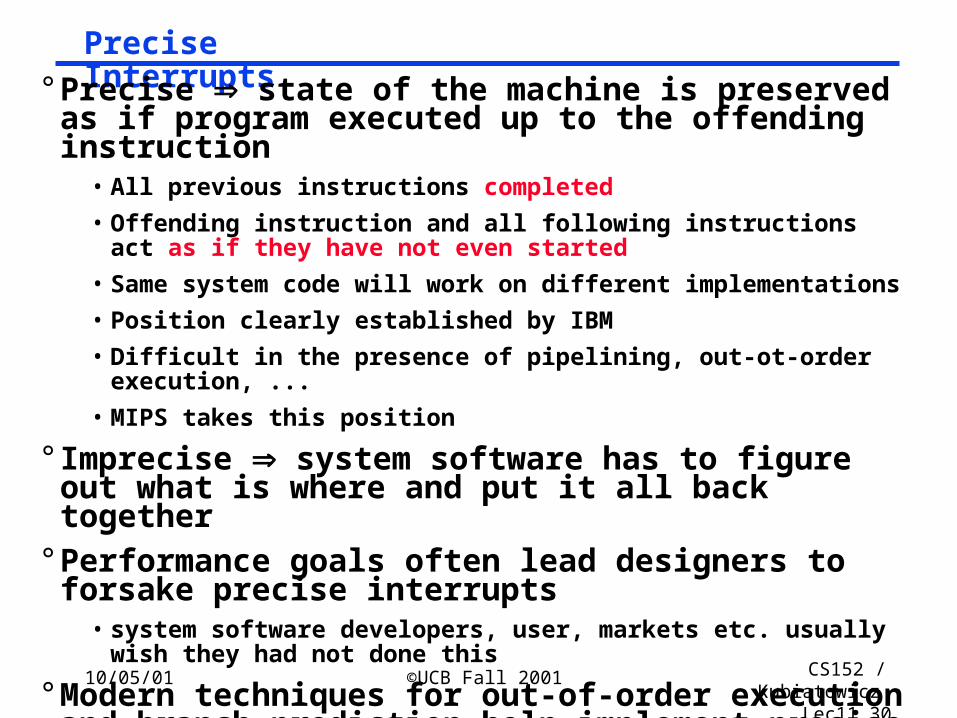
Precise Interrupts° Precise state of the machine is preserved as if
program executed up to the offending instruction• All previous instructions completed
• Offending instruction and all following instructions act as if they have not even started
• Same system code will work on different implementations
• Position clearly established by IBM
• Difficult in the presence of pipelining, out-ot-order execution, ...
• MIPS takes this position
° Imprecise system software has to figure out what is where and put it all back together
° Performance goals often lead designers to forsake precise interrupts
• system software developers, user, markets etc. usually wish they had not done this
° Modern techniques for out-of-order execution and branch prediction help implement precise interrupts
Page 31
10/05/01 ©UCB Fall 2001 CS152 / Kubiatowicz
Lec11.31
Big Picture: user / system modes° By providing two modes of execution (user/system) it is possible for the computer to manage itself
• operating system is a special program that runs in the privileged mode and has access to all of the resources of the computer
• presents “virtual resources” to each user that are more convenient that the physical resources
- files vs. disk sectors
- virtual memory vs physical memory
• protects each user program from others
• protects system from malicious users.• OS is assumed to “know best”, and is trusted code, so enter
system mode on exception.
° Exceptions allow the system to taken action in response to events that occur while user program is executing:
• Might provide supplemental behavior (dealing with denormal floating-point numbers for instance).
• “Unimplemented instruction” used to emulate instructions that were not included in hardware (I.e. MicroVax)
Page 32
10/05/01 ©UCB Fall 2001 CS152 / Kubiatowicz
Lec11.32
Addressing the Exception Handler
° Traditional Approach: Interupt Vector• PC <- MEM[ IV_base + cause || 00]
• 370, 68000, Vax, 80x86, . . .
° RISC Handler Table• PC <– IT_base + cause || 0000
• saves state and jumps
• Sparc, PA, M88K, . . .
° MIPS Approach: fixed entry• PC <– EXC_addr
• Actually very small table
- RESET entry
- TLB
- other
iv_basecause
handlercode
iv_basecause
handler entry code
Page 33
10/05/01 ©UCB Fall 2001 CS152 / Kubiatowicz
Lec11.33
Saving State
° Push it onto the stack• Vax, 68k, 80x86
° Shadow Registers• M88k
• Save state in a shadow of the internal pipeline registers
° Save it in special registers• MIPS EPC, BadVaddr, Status, Cause
Page 34
10/05/01 ©UCB Fall 2001 CS152 / Kubiatowicz
Lec11.34
Additions to MIPS ISA to support Exceptions?° Exception state is kept in “coprocessor 0”.
• Use mfc0 read contents of these registers• Every register is 32 bits, but may be only partially defined
BadVAddr (register 8)• register contained memory address at which memory reference occurred
Status (register 12) • interrupt mask and enable bits
Cause (register 13)• the cause of the exception• Bits 5 to 2 of this register encodes the exception type (e.g undefined
instruction=10 and arithmetic overflow=12)
EPC (register 14)• address of the affected instruction (register 14 of coprocessor 0).
° Control signals to write BadVAddr, Status, Cause, and EPC° Be able to write exception address into PC (8000 0080hex)° May have to undo PC = PC + 4, since want EPC to point to offending
instruction (not its successor): PC = PC - 4
Page 35
10/05/01 ©UCB Fall 2001 CS152 / Kubiatowicz
Lec11.35
Details of Status register
° Mask = 1 bit for each of 5 hardware and 3 software interrupt levels
• 1 => enables interrupts• 0 => disables interrupts
° k = kernel/user• 0 => was in the kernel when interrupt occurred• 1 => was running user mode
° e = interrupt enable• 0 => interrupts were disabled• 1 => interrupts were enabled
° When interrupt occurs, 6 LSB shifted left 2 bits, setting 2 LSB to 0
• run in kernel mode with interrupts disabled
Status
15 8 5 4 3 2 1 0
k e k e k eMask
old prev current
Page 36
10/05/01 ©UCB Fall 2001 CS152 / Kubiatowicz
Lec11.36
Details of Cause register
° Pending interrupt 5 hardware levels: bit set if interrupt occurs but not yet serviced
• handles cases when more than one interrupt occurs at same time, or while records interrupt requests when interrupts disabled
° Exception Code encodes reasons for interrupt• 0 (INT) => external interrupt
• 4 (ADDRL) => address error exception (load or instr fetch)
• 5 (ADDRS) => address error exception (store)
• 6 (IBUS) => bus error on instruction fetch
• 7 (DBUS) => bus error on data fetch
• 8 (Syscall) => Syscall exception
• 9 (BKPT) => Breakpoint exception
• 10 (RI) => Reserved Instruction exception
• 12 (OVF) => Arithmetic overflow exception
Status15 10
Pending
5 2
Code
Page 37
10/05/01 ©UCB Fall 2001 CS152 / Kubiatowicz
Lec11.37
Part of the handler in trap_handler.s.ktext 0x80000080
entry: Exceptions/interrupts come here.set noat
move $k1 $at # Save $at
.set at
sw $v0 s1 # Not re-entrent and we can't trust $sp
sw $a0 s2
mfc0 $k0 $13 # Cause Grab the cause registerli $v0 4 # syscall 4 (print_str)
la $a0 __m1_
syscall
li $v0 1 # syscall 1 (print_int)
srl $a0 $k0 2 # shift Cause reg
syscall
ret: lw $v0 s1
lw $a0 s2
mfc0 $k0 $14 # EPC Get the return address (EPC).set noat
move $at $k1 # Restore $at
.set at
rfe # Return from exception handler
addiu $k0 $k0 4 # Return to next instruction
jr $k0
Page 38
10/05/01 ©UCB Fall 2001 CS152 / Kubiatowicz
Lec11.38
Example: How Control Handles Traps in our FSD
° Undefined Instruction–detected when no next state is defined from state 1 for the op value.
• We handle this exception by defining the next state value for all op values other than lw, sw, 0 (R-type), jmp, beq, and ori as new state 12.
• Shown symbolically using “other” to indicate that the op field does not match any of the opcodes that label arcs out of state 1.
° Arithmetic overflow–detected on ALU ops such as signed add
• Used to save PC and enter exception handler
° External Interrupt – flagged by asserted interrupt line• Again, must save PC and enter exception handler
° Note: Challenge in designing control of a real machine is to handle different interactions between instructions and other exception-causing events such that control logic remains small and fast.
• Complex interactions makes the control unit the most challenging aspect of hardware design
Page 39
10/05/01 ©UCB Fall 2001 CS152 / Kubiatowicz
Lec11.39
How add traps and interrupts to state diagram?
IR <= MEM[PC]PC <= PC + 4
R-type
S <= A fun B
R[rd] <= S
S <= A op ZX
R[rt] <= S
ORi
S <= A + SX
R[rt] <= M
M <= MEM[S]
LW
S <= A + SX
MEM[S] <= B
SW
“instruction fetch”
“decode”
0000
0001
0100
0101
0110
0111
1000
1001
1010
1011
1100
BEQ
0010
If A = Bthen PC <= S
S<= PC +SX
undefined instruction
EPC <= PC - 4PC <= exp_addrcause <= 10 (RI)
other
S <= A - B
overflow
EPC <= PC - 4PC <= exp_addrcause <= 12 (Ovf)
EPC <= PC - 4PC <= exp_addrcause <= 0(INT)
HandleInterrupt
Pending INT
Page 40
10/05/01 ©UCB Fall 2001 CS152 / Kubiatowicz
Lec11.40
But: What has to change in our -sequencer?
° Need concept of branch at micro-code level
R-type
S <= A fun B0100
overflow
EPC <= PC - 4PC <= exp_addrcause <= 12 (Ovf)
µAddressSelectLogic
Opcode
microPC
1
Ad
der
DispatchROM
Mux
0012
Mux
Mux
0
1
overflowpending interrupt
4?
N?
Cond SelectDo -branch
-offset Seq Select
Page 41
10/05/01 ©UCB Fall 2001 CS152 / Kubiatowicz
Lec11.41
Summary° Microprogramming is a fundamental concept
• implement an instruction set by building a very simple processor and interpreting the instructions
• essential for very complex instructions and when few register transfers are possible
• Control design reduces to Microprogramming
° Exceptions are the hard part of control• Need to find convenient place to detect exceptions and to branch to
state or microinstruction that saves PC and invokes the operating system
• Providing clean interrupt model gets hard with pipelining!
° Precise Exception state of the machine is preserved as if program executed up to the offending instruction
• All previous instructions completed
• Offending instruction and all following instructions act as if they have not even started
Page 42
10/05/01 ©UCB Fall 2001 CS152 / Kubiatowicz
Lec11.42
Thought: Microprogramming one inspiration for RISC
° If simple instruction could execute at very high clock rate…
° If you could even write compilers to produce microinstructions…
° If most programs use simple instructions and addressing modes…
° If microcode is kept in RAM instead of ROM so as to fix bugs …
° If same memory used for control memory could be used instead as cache for “macroinstructions”…
° Then why not skip instruction interpretation by a microprogram and simply compile directly into lowest language of machine? (microprogramming is overkill when ISA matches datapath 1-1)