46
Lecture 4, Patterns-I CS294-88, UC Berkeley, Spring 2013 CS294-88 Declarative Hardware Design Lecture 4: Patterns Part I Jonathan Bachrach and Krste Asanovic , UC Berkeley Spring 2013

Lecture 4, Patterns-I CS294-88, UC Berkeley, Spring 2013
CS294-88 Declarative Hardware Design
Lecture 4: Patterns Part I
Jonathan Bachrach and Krste Asanovic,UC BerkeleySpring 2013

Lecture 4, Patterns-I CS294-88, UC Berkeley, Spring 2013
Patterns Review
2

Lecture 4, Patterns-I CS294-88, UC Berkeley, Spring 2013
A Common Design Problem
3
The shift register is an abstraction of any synchronous pipelined block of logic that accepts input data and produces output data, where input and output might not be ready every clock cycle
How to manage growth in control logic complexity?
Valid? Ready?Stage 1 Stage 2 Stage 3 Stage 4

Lecture 4, Patterns-I CS294-88, UC Berkeley, Spring 2013
Solution: Decouple Units with FIFOs
4
ConsumerProcessing
Pipeline
Pipeline only cares whether space in FIFO, not about whether consumer can take next value
Breaks combinational path between pipeline control logic and consumer control logic
For full throughput with decoupling, need at least two elements in FIFO
With only one element, have to ping-pong between pipeline enqueue and consumer dequeueAllowing both enqueue and dequeue in same cycle to single-element FIFO destroys decoupling (back to a synchronous connection)

Lecture 4, Patterns-I CS294-88, UC Berkeley, Spring 2013
Decoupled Design Discipline
Many large digital designs are divided into local synchronous pipelines, or units, connected via decoupling FIFOs
Approx. 10K-100K gates per unit
Decoupled units may have different clocksIn which case, need asynchronous FIFOs
5
Lecture 4, Patterns-I CS294-88, UC Berkeley, Spring 2013
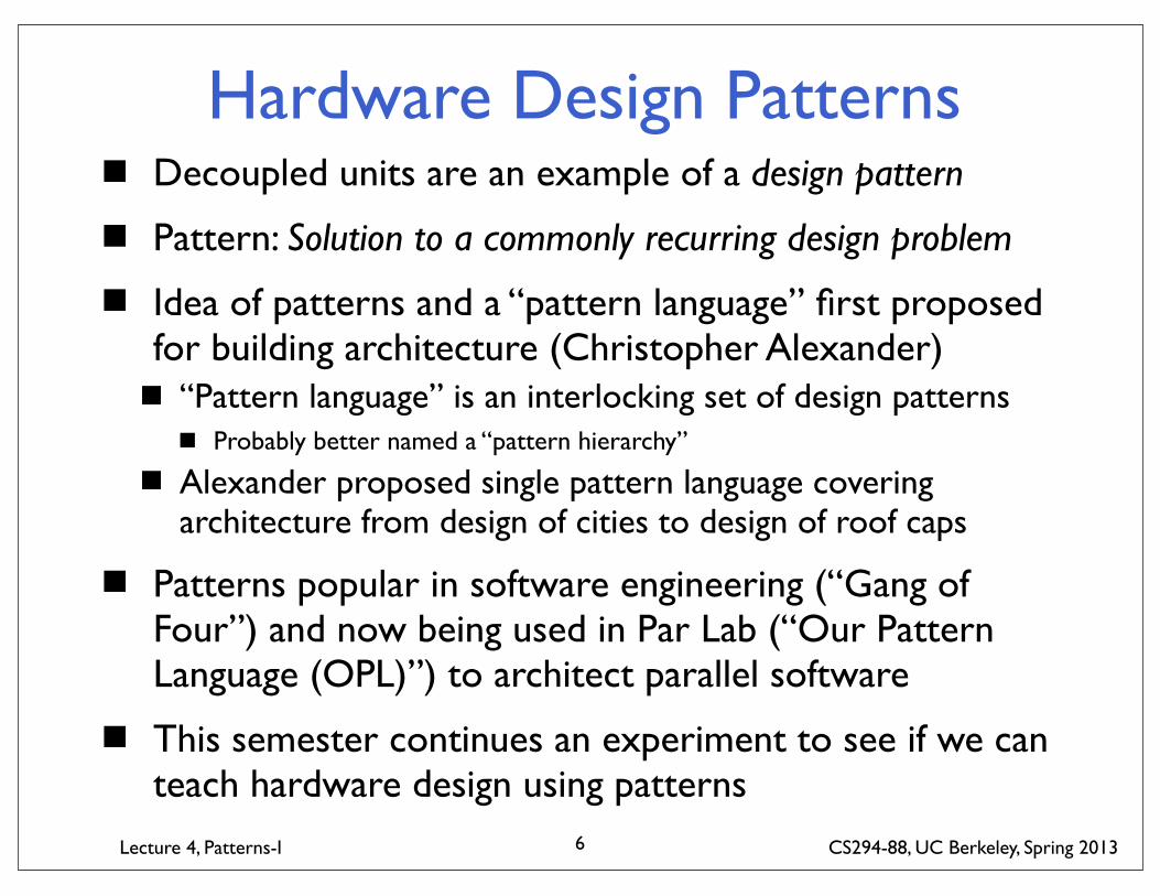
Hardware Design PatternsDecoupled units are an example of a design pattern
Pattern: Solution to a commonly recurring design problem
Idea of patterns and a “pattern language” first proposed for building architecture (Christopher Alexander)
“Pattern language” is an interlocking set of design patternsProbably better named a “pattern hierarchy”
Alexander proposed single pattern language covering architecture from design of cities to design of roof caps
Patterns popular in software engineering (“Gang of Four”) and now being used in Par Lab (“Our Pattern Language (OPL)”) to architect parallel software
This semester continues an experiment to see if we can teach hardware design using patterns
6
Lecture 4, Patterns-I CS294-88, UC Berkeley, Spring 2013
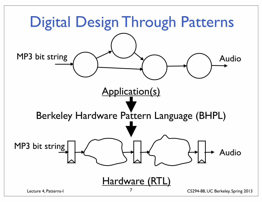
Digital Design Through Patterns
Application(s)
MP3 bit string Audio
Hardware (RTL)
MP3 bit stringAudio
Berkeley Hardware Pattern Language (BHPL)
7
Lecture 4, Patterns-I CS294-88, UC Berkeley, Spring 2013
BHPL GoalsBHPL captures problem-solution pairs for creating hardware designs (machines) to execute applications
BHPL Non-GoalsDoesn’t describe applications themselves, only machines that execute applications and strategies for mapping applications onto machines
8
Lecture 4, Patterns-I CS294-88, UC Berkeley, Spring 2013
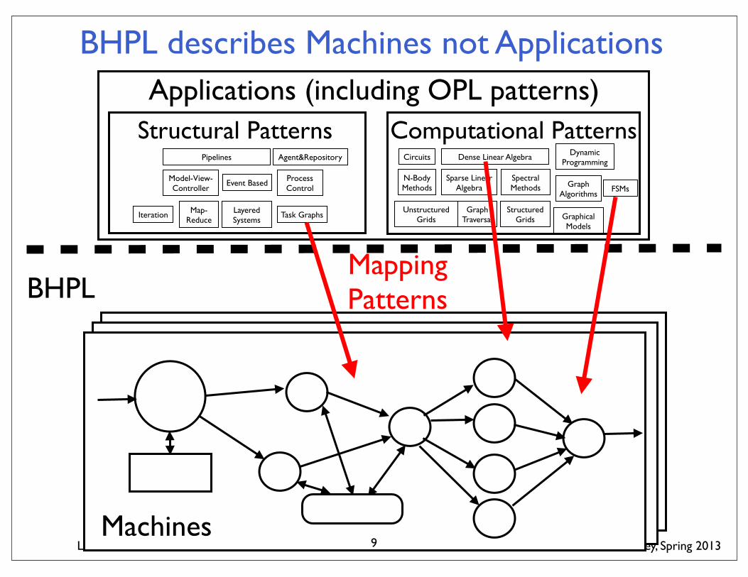
BHPL describes Machines not Applications
Dense Linear Algebra
Sparse Linear Algebra
Spectral Methods FSMsGraph
Algorithms
Circuits
N-Body Methods
Dynamic Programming
Computational Patterns
Graph Traversal
Structured Grids
Unstructured Grids Graphical
Models
Pipelines
Model-View-Controller
Event Based Process Control
Agent&Repository
Structural Patterns
Map-Reduce
Iteration Layered Systems
Task Graphs
Applications (including OPL patterns)
Machines
BHPLMapping Patterns
9

Lecture 4, Patterns-I CS294-88, UC Berkeley, Spring 2013
BHPL 0.5 OverviewApplications (including OPL patterns)
BHPLFFT to
SIMD arrayApp-to-UTL Mappings Layer
Problem: Application ComputationSolution: UTL Machine
UTL-to-UTL Transformation Layer
Time-Multiplexing
Problem: UTL violates constraint (too big, too slow)Solution: Transformed UTLUnrolling
UTL-to-RTL Transformation Layer
Microcoded Engine
In-Order Pipeline Engine
Problem: UTL designSolution: RTL behavior
RTL-to-TechnologyFIFO CAM
Interleaved Memory Problem: RTL behavior
Solution: Structural design10

Lecture 4, Patterns-I CS294-88, UC Berkeley, Spring 2013
Pattern Template (Name here)Problem: Describe the particular problem the pattern is meant to solve. Should include some context (small, high throughput), and also the layer of the pattern hierarchy where it fits.
Solution: Describe the solution, which should be some hardware structure with a figure. Solution is usually the pattern name. Should not provide a family of widely varying solutions - these should be separate patterns, possibly grouped under a single more abstract parent pattern.
Applicability: Longer discussion of where this particular solution would normally be used, or where it would not be used.
Consequences: Issues that arise when using this pattern, but only for cases where it is appropriate to use (use Applicability to delineate cases where it is not appropriate to use). These might point at sub-problems for which there are sub-patterns. There might also be limitations on resulting functionality, or implications in design complexity, or CAD tool use etc.
11
Lecture 4, Patterns-I CS294-88, UC Berkeley, Spring 2013
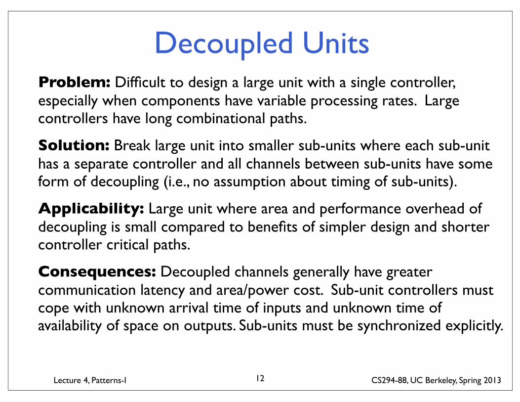
Decoupled UnitsProblem: Difficult to design a large unit with a single controller, especially when components have variable processing rates. Large controllers have long combinational paths.
Solution: Break large unit into smaller sub-units where each sub-unit has a separate controller and all channels between sub-units have some form of decoupling (i.e., no assumption about timing of sub-units).
Applicability: Large unit where area and performance overhead of decoupling is small compared to benefits of simpler design and shorter controller critical paths.
Consequences: Decoupled channels generally have greater communication latency and area/power cost. Sub-unit controllers must cope with unknown arrival time of inputs and unknown time of availability of space on outputs. Sub-units must be synchronized explicitly.
12

Lecture 4, Patterns-I CS294-88, UC Berkeley, Spring 2013
Decoupled Units
SharedMemory
Network
Unless shared memory is truly multiported, channels to memory must be decoupled
Channels to network are
usually decoupled in any case
13

Lecture 4, Patterns-I CS294-88, UC Berkeley, Spring 2013
Related Patterns
14
Often multiple solutions to same problem, but which to pick depends on situation
Problem statement and Applicability text should help select the correct pattern to use
Example: Pipelined versus multi-cycle operators when delay through operator exceeds desired cycle time

Lecture 4, Patterns-I CS294-88, UC Berkeley, Spring 2013
Pipelined OperatorProblem: Combinational function of operator has long critical path that would reduce system clock frequency. High throughput of this function is required.
Solution: Divide combinational function using pipeline registers such that logic in each stage has critical path below desired cycle time. Improve throughput by initiating new operation every clock cycle overlapped with propagation of earlier operations down pipeline.
Applicability: Operators that require high throughput but where latency is not critical.
Consequences: Latency of function increases due to propagation through pipeline registers, adds energy/op. Any associated controller might have to track execution of operation across multiple cycles.
15

Lecture 4, Patterns-I CS294-88, UC Berkeley, Spring 2013
Pipelined Operator
Clock Clock Clock
Clock Clock
f(g(in))
g(in) f(in)
16
Lecture 4, Patterns-I CS294-88, UC Berkeley, Spring 2013
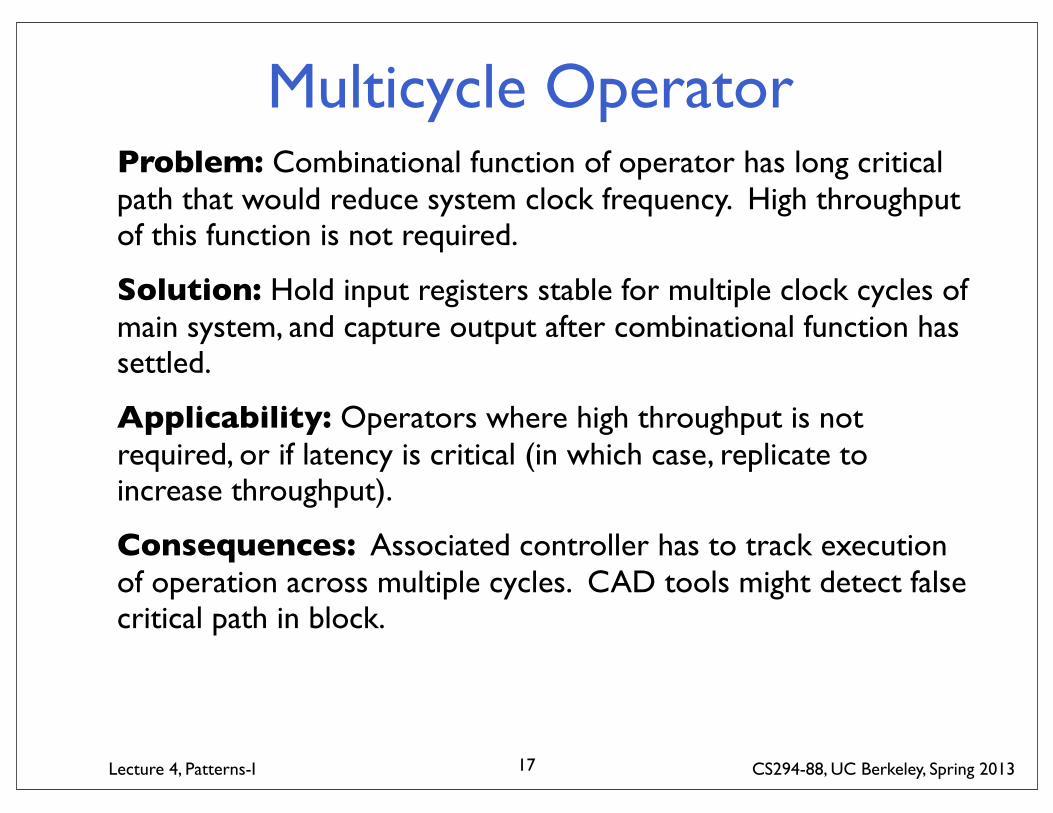
Multicycle OperatorProblem: Combinational function of operator has long critical path that would reduce system clock frequency. High throughput of this function is not required.
Solution: Hold input registers stable for multiple clock cycles of main system, and capture output after combinational function has settled.
Applicability: Operators where high throughput is not required, or if latency is critical (in which case, replicate to increase throughput).
Consequences: Associated controller has to track execution of operation across multiple cycles. CAD tools might detect false critical path in block.
17

Lecture 4, Patterns-I CS294-88, UC Berkeley, Spring 2013
Multicycle Operator
Clock/2 Clock/2
Clock Clock
f(g(in))
f(g(in))
18

Lecture 4, Patterns-I CS294-88, UC Berkeley, Spring 2013
Some Families of Patterns
19

Lecture 4, Patterns-I CS294-88, UC Berkeley, Spring 2013
Multiport Memory PatternsProvides multiple access ports to a common memory
True Multiport Memory
Banked Multiport MemoryInterleave lesser-ported banks to provide higher bandwidth
Cached Multiport MemoryUse large single-port main memory, but add cache to service requests for each access port
20

Lecture 4, Patterns-I CS294-88, UC Berkeley, Spring 2013
Controller PatternsSynchronous control of local datapathState Machine Controller
control lines generated by state machineMicrocoded Controller
single-cycle datapath, control lines in ROM/RAMIn-Order Pipeline Controller
pipelined control, dynamic interaction between stagesOut-of-Order Pipeline Controller
operations within a control stream might be reordered internally
Threaded Pipeline Controllermultiple control streams one execution pipelinecan be either in-order (PPU) or out-of-order
21

Lecture 4, Patterns-I CS294-88, UC Berkeley, Spring 2013
Network PatternsConnects multiple units using shared resources
BusLow-cost, ordered
CrossbarHigh-performance
Multi-stage networkTrade cost/performance
22
Lecture 4, Patterns-I CS294-88, UC Berkeley, Spring 2013
Chiseling Patterns
How will patterns be implemented in Chisel libraries?
How will different levels of the pattern language compose
23

Lecture 4, Patterns-I CS294-88, UC Berkeley, Spring 2013
BHPL 0.5 OverviewApplications (including OPL patterns)
BHPLFFT to
SIMD arrayApp-to-UTL Mappings Layer
Problem: Application ComputationSolution: UTL Machine
UTL-to-UTL Transformation Layer
Time-Multiplexing
Problem: UTL violates constraint (too big, too slow)Solution: Transformed UTLUnrolling
UTL-to-RTL Transformation Layer
Microcoded Engine
In-Order Pipeline Engine
Problem: UTL designSolution: RTL behavior
RTL-to-TechnologyFIFO CAM
Interleaved Memory Problem: RTL behavior
Solution: Structural design24
Lecture 4, Patterns-I CS294-88, UC Berkeley, Spring 2013
App -> UTL in Chisel
25
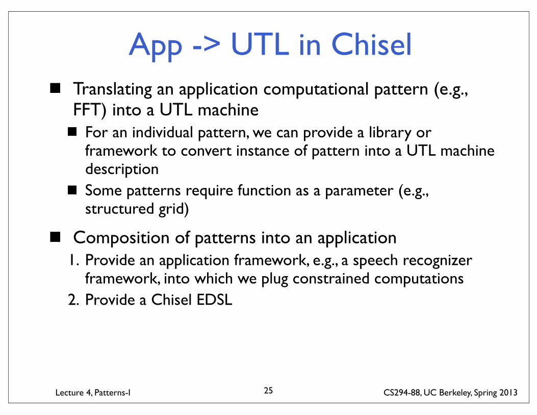
Translating an application computational pattern (e.g., FFT) into a UTL machine
For an individual pattern, we can provide a library or framework to convert instance of pattern into a UTL machine descriptionSome patterns require function as a parameter (e.g., structured grid)
Composition of patterns into an application1. Provide an application framework, e.g., a speech recognizer
framework, into which we plug constrained computations2. Provide a Chisel EDSL

Lecture 4, Patterns-I CS294-88, UC Berkeley, Spring 2013
Transactional Specification of Unit
Each transaction has a combinational guard function defined over local state and state of I/O indicating when it can fire
e.g., only fire when head of input queue present and of certain typeTransaction mutates local state and performs I/O when it firesScheduler is combinational function that picks next ready transaction to fire
26
Architectural State
Trans 1Trans 1Trans 1Trans 1TransactionScheduler
Network
Memory

Lecture 4, Patterns-I CS294-88, UC Berkeley, Spring 2013
UTL Example: Route Lookup
Transactions in decreasing scheduler priorityTable_Write (request on table access queue)
– Writes a given 12-bit value to a given 12-bit address
Table_Read (request on table access queue)– Reads a 12-bit value given a 12-bit address, puts response on table reply queue
Route (request on packet input queue)– Looks up header in table and places routed packet on correct output queue
This level of detail is all the information we really need to understand what the unit is supposed to do! Everything else is implementation.
27
Packet Input
Packet Output QueuesLookup Table
Table Access Table Replies
Table_Write
Table_Read
Route
Scheduler

Lecture 4, Patterns-I CS294-88, UC Berkeley, Spring 2013
Refining Route Lookup to RTL
The reorder buffer, the trie lookup pipeline’s registers, and any control state are microarchitectural state that should not affect function as viewed from outside
Implementation must ensure atomicity of UTL transactions:– Reorder buffer ensures packets flow through unit in order– Must also ensure table write doesn’t appear to happen in middle of packet lookup, e.g., wait
for pipeline to drain before performing write
28
Packet Input
Packet Output Queues
Lookup RAM
Table Access Table Replies
Reorder Buffer
Trie Lookup Pipeline
Control

Lecture 4, Patterns-I CS294-88, UC Berkeley, Spring 2013
Architectural StateThe architectural state of a unit is that which is visible from outside the unit through I/O operations
i.e., architectural state is part of the spec(this is the target for “black-box” testing)
When a unit is refined into RTL, there will usually be additional microarchitectural state that is not visible from outside
Intra-transaction sequencing logicPipeline registersInternal caches and/or buffers(this is the target for “white-box” testing)
29

Lecture 4, Patterns-I CS294-88, UC Berkeley, Spring 2013
UTL->UTLTransactional actor as common representation of a unit?
e.g., Actor hierarchy (SDF, Kahn, Transactional Actor)
These are transformations within a single level of representation, analogous to compiler transformations
e.g., loop unrolling, time-multiplexing
Authors provide transformation passes, constrained by types of units they can transform?
e.g., loop unrolling for stateless units only
Design-space exploration tools manipulate the parameters exposed by these transformation passes?
30

Lecture 4, Patterns-I CS294-88, UC Berkeley, Spring 2013
UTL->RTLAnalogous to back-end of software compiler
Convert certain types of unit into pipelined RTL engines
31

Lecture 4, Patterns-I CS294-88, UC Berkeley, Spring 2013
Processing Unit Design Patterns
32

Lecture 4, Patterns-I CS294-88, UC Berkeley, Spring 2013
Control+DatapathProblem: Arithmetic operations within transaction require large functional units and memories connected by wide buses. Sequencing of operations within transaction is complex.
Solution: Split processing unit into 1) datapath,which contains functional units, data memories, and their interconnect, and 2) control, which contains all sequencing logic.
Applicability: Where there is a clear divide between control logic and data processing logic, with relatively few signals crossing this divide, and mostly from control to datapath not vice versa.
Consequences: Most design errors are confined to the control portion. Same datapath design can perform many different transactions by changing control sequencing. Paths between control and datapath, particularly from datapath back to control, are often timing critical.
33

Lecture 4, Patterns-I CS294-88, UC Berkeley, Spring 2013
Control+Datapath
34
RAM
Datapath
Control

Lecture 4, Patterns-I CS294-88, UC Berkeley, Spring 2013
Controller PatternsFor synchronous control of local datapathState Machine Controller
control lines generated by state machineMicrocoded Controller
single-cycle datapath, control lines in ROM/RAMIn-Order Pipeline Controller
control pipelined datapath, dynamic interaction between stagesOut-of-Order Pipeline Controller
operations within a control stream might be reordered internally
Threaded Pipeline Controllermultiple control streams, one execution pipeline
35

Lecture 4, Patterns-I CS294-88, UC Berkeley, Spring 2013
Control DecompositionCan divide control functions into three categories:
36
Transaction Scheduling
Transaction Sequencing
Pipeline Control
Pick next transaction to be executed
Sequence operations within transaction
Control execution of operations on pipelined datapath
To datapath From datapath

Lecture 4, Patterns-I CS294-88, UC Berkeley, Spring 2013
State Machine ControllerProblem: Control for a simple unit that performs a single transaction at a time.
Solution: Construct state machine with a common initial state to select next transaction, and a separate path for each transaction to sequence operations for that transaction.
Applicability: Where datapath is not highly pipelined and where unit only executes one non-overlapping transaction at a time. Combinational control logic can expand dramatically as number of states increases, so limited to less pipelined and less concurrent units.
Consequences: State machine can be more compact and faster than a microcode controller for small state machines. Changes in unit functionality can cause large changes in size/speed of state machine.
37

Lecture 4, Patterns-I CS294-88, UC Berkeley, Spring 2013
State Machine Controller
38
S
T1A
T1B
T1C
T2A
T2B

Lecture 4, Patterns-I CS294-88, UC Berkeley, Spring 2013
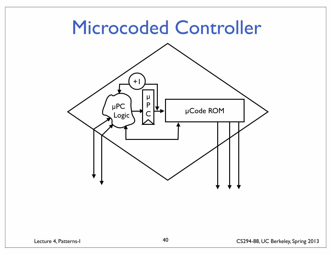
Microcoded ControllerProblem: Control for a complex unit that performs a single transaction at a time.
Solution: Encode control lines in a ROM structure with a small state machine to sequence through locations in ROM. Microcode dispatch function selects next transaction to execute, and each transaction executed by sequence in microcode ROM. Can also use RAM structure to allow post-fabrication modifications to control.
Applicability: Where unit only executes one non-overlapping transaction at a time, but where control is complex. Particularly useful in technology where ROM bits are significantly cheaper than logic gates.
Consequences: Microcode easily modified to make changes in unit functionality. Unit cycle time can be limited by critical path from ROM readout to ROM address input (can use pipelined microcode engine to speed throughput inbetween control hazards).
39
Lecture 4, Patterns-I CS294-88, UC Berkeley, Spring 2013
Microcoded Controller
40
µPC Logic
µPC µCode ROM
+1

Lecture 4, Patterns-I CS294-88, UC Berkeley, Spring 2013
In-Order Pipeline ControllerProblem: Control for a complex pipelined unit that can overlap execution of multiple transactions, and multiple operations within one transaction.
Solution: Generate control signals for each stage of pipeline using control state pipelined along with data state. Use dynamic scoreboard (part of which may be the pipelined control state) to track operations in flight in pipeline. Next operation can only enter pipeline when scoreboard indicates this would not create a pipelining hazard (structural, data, or control).
Applicability: Where unit’s datapath is pipelined and either sequence of transactions or sequence of operations within a transaction is dynamically determined by input data. Where in-order processing is required, or sufficient for performance goals.
Consequences: The datapath design mandates the hazards generated by an executing operation, and can cause large growth in scoreboard complexity and reduction in performance unless hazards on common sequences are avoided.
41

Lecture 4, Patterns-I CS294-88, UC Berkeley, Spring 2013
In-Order Pipeline Controller
42
Select next xaction or next op in
current xaction
Scoreboard
Issue?
Lecture 4, Patterns-I CS294-88, UC Berkeley, Spring 2013
Out-of-Order Processing UnitWhen in-order gives insufficient throughput, buffer operations and issue out-of-order with respect to hazards.
43

Lecture 4, Patterns-I CS294-88, UC Berkeley, Spring 2013
Threaded Processing UnitMultiplex multiple transaction streams onto single hardware unit.
One specific implementation of time-multiplexing.
44

Lecture 4, Patterns-I CS294-88, UC Berkeley, Spring 2013
Taxonomy of Control StrategiesIncreasing levels of control complexity build on each other.
45
Transaction Scheduling
Transaction Sequencing
Pipeline Control
To datapath From datapath
SM µCode In-Order OoO Threaded
Next state after idle
state
Dispatch on transaction
state to µcode address
Initialize current transaction
state
Initialize current
transaction state
Interleave transactions
from multiple units
State transitions
Step through µcode
Sequence through
transaction states (either
FSM or uCode)
same as In-Order
Same as In-Order, except
multiple simultaneous
xactions expanded
N/A N/A
Control state pipelined along
with data. Scoreboard
controls issue of next in-order
operation
Control state pipelined along with data. Issue
buffer executes operation
out-of-order
Control state pipelined along with data. Issue
next operation from ready
xaction.

Lecture 4, Patterns-I CS294-88, UC Berkeley, Spring 2013
BHPL 0.5 OverviewApplications (including OPL patterns)
BHPLFFT to
SIMD arrayApp-to-UTL Mappings Layer
Problem: Application ComputationSolution: UTL Machine
UTL-to-UTL Transformation Layer
Time-Multiplexing
Problem: UTL violates constraint (too big, too slow)Solution: Transformed UTLUnrolling
UTL-to-RTL Transformation Layer
Microcoded Engine
In-Order Pipeline Engine
Problem: UTL designSolution: RTL behavior
RTL-to-TechnologyFIFO CAM
Interleaved Memory Problem: RTL behavior
Solution: Structural design46


![SP07 cs294 lecture 12 -- phrase decoding.ppt [Read-Only]klein/cs294-7/SP07 cs294 lecture 12 -- phrase...frais .. Learning weights has been tried, several times: [Marcu and Wong, 02]](https://static.documents.pub/doc/80x56/60884626f3c87844cf22b82c/sp07-cs294-lecture-12-phrase-read-only-kleincs294-7sp07-cs294-lecture-12.jpg)
![SP07 cs294 lecture 18 -- semantic roles.ppt [Read-Only]klein/cs294-7/SP07 cs294 lecture … · Lecture 18: Semantic Roles Dan Klein – UC Berkeley Includes examples from Johnson,](https://static.documents.pub/doc/80x56/6002ecf9207845229a588a36/sp07-cs294-lecture-18-semantic-rolesppt-read-only-kleincs294-7sp07-cs294.jpg)


![UCB CS294-88: Declarative Design [0.2cm] Chisel Overviewinst.eecs.berkeley.edu/~cs294-88/sp13/lectures/chisel-review.pdf · UCB CS294-88: Declarative Design Chisel Overview Jonathan](https://static.documents.pub/doc/80x56/60417694dde8db15be43b6a8/ucb-cs294-88-declarative-design-02cm-chisel-cs294-88sp13lectureschisel-reviewpdf.jpg)


