CS422 C t Nt k Computer Networks Lecture 5 Network Layer Dr. Xiaobo Zhou Department of Computer Science CS422 Network Layer.1 UC. Colorado Springs Network Layer ° Network Layer: the most complex layer • Requires the coordinated actions of multiple, geographically distributed network elements (switches & routers) distributed network elements (switches & routers) • Must be able to deal with very large scales - Billions of users (people & communicating devices) • Biggest Challenges - Addressing: where should information be directed to? CS422 Network Layer.2 UC. Colorado Springs - Routing: what path should be used to get information there?
Transcript
CS422C t N t kComputer Networks
Lecture 5 Network Layer
Dr. Xiaobo ZhouDepartment of Computer Science
CS422 Network Layer.1 UC. Colorado Springs
Network Layer
° Network Layer: the most complex layer• Requires the coordinated actions of multiple, geographically
distributed network elements (switches & routers)distributed network elements (switches & routers)
• Must be able to deal with very large scales
- Billions of users (people & communicating devices)
• Biggest Challenges
- Addressing: where should information be directed to?
CS422 Network Layer.2 UC. Colorado Springs
- Routing: what path should be used to get information there?
t0 t1
Packet Switching
Network
° Transfer of information as payload in data packets
CS422 Network Layer.3 UC. Colorado Springs
Transfer of information as payload in data packets
° Packets undergo random delays & possible loss
° Different applications impose differing requirements on the transfer of information
Network Layer Functions
What are essential?° Routing: mechanisms for determining the set of best paths for
routing packetsg p° Forwarding: transfer of packets from inputs to outputs° Priority & Scheduling: determining order of packet transmission
I l t ti f C ti l S i• Implementation of Connectionless Service
• Implementation of Connection-Oriented Service
• Comparison of Virtual-Circuit and Datagram Subnets
CS422 Network Layer.5 UC. Colorado Springs
Store-and-Forward Packet Switching
° The environment of the network layer protocols for end-to-end transmission.
fig 5-1
CS422 Network Layer.6 UC. Colorado Springs
Why a packet must be stored until it has fully arrived then forwarded?
Implementation of Connectionless Service
Routing within a diagram subnet.
Routing in a datagram subnet
CS422 Network Layer.7 UC. Colorado Springs
Routing in a datagram subnet.
Destinationaddress
Outputport
Routing Tables in Datagram Networks
° Route determined by table lookup
1345 12
70785
61566
° Routing decision involves finding next hop in route to given destination
° Routing table has an entry for each destination specifying output port that leads to next hop
CS422 Network Layer.8 UC. Colorado Springs
2458 12
leads to next hop
° Size of table becomes impractical for very large number of destinations
Example: Internet Routing
° Internet protocol uses datagram packet switching across networks• Networks are treated as data links
° Hosts have two part IP address:° Hosts have two-part IP address:• Network address + Host address
° Routers do table lookup on network address• This reduces size of routing table
° In addition, network addresses are assigned so that they can also be aggregated• Discussed as addressing and CIDR (super netting)
CS422 Network Layer.9 UC. Colorado Springs
• Discussed as addressing and CIDR (super-netting)
Implementation of Connection-Oriented Service
Routing within a virtual-circuit subnet.
CS422 Network Layer.10 UC. Colorado Springs
Label switching
Does VC subnets need the capability to route isolated packets from an arbitrary source to an arbitrary destination?
SW 1
SW 2
SW n
Connect request
Connect request
Connect request
Connect confirm
Connect confirm
Connect confirm
…
Connection Setup
confirm confirmconfirm
° Signaling messages propagate as route is selected° Signaling messages identify connection and setup tables in
switches° Typically a connection is identified by a local tag, Virtual Circuit
Resources do not need to be dedicated to VCs.
CS422 Network Layer.11 UC. Colorado Springs
yp y y g,Identifier (VCI)
° Each switch only needs to know how to relate an incoming tag in one input to an outgoing tag in the corresponding output
° Once tables are setup, packets can flow along path
Two Tradeoffs of Virtual Circuits and Datagrams
Router memory space vs. bandwidth
Address length vs. # of entries
CS422 Network Layer.12 UC. Colorado Springs
setup time vs. address parsing time
QoS vs. congestion avoidance
Comparison of Virtual-Circuit and Datagram Subnets
5-4
CS422 Network Layer.13 UC. Colorado Springs
Routing Algorithms
° Routing algorithms: part of the network layer software responsible for deciding which output lines an incoming packet should be transmitted on
° Static vs. adaptive routingp g• The Optimality Principle
• Shortest Path Routing
• Flooding
• Distance Vector Routing (RIP)
• Link State Routing (OSPF)
• Hierarchical Routing
CS422 Network Layer.14 UC. Colorado Springs
Hierarchical Routing
• Broadcast Routing
• Multicast Routing
• Routing for Mobile Hosts
• Routing in Ad Hoc Networks
Routing Algorithms (2)
° Desirable routing properties, but often contradictory• Correctness• Simplicity• Robustness
Q1: why there are contradictory goals? Optimality vs. fairness
• Stability• Fairness• optimality
Should X-X’ traffic be shut off to maximizethe total flow on the horizontal link?
CS422 Network Layer.15 UC. Colorado Springs
The Optimality Principle° Optimality principle: if router J is on the optimal path from
router I to router K, then the optimal path from J to K also falls along the same route.
X
CS422 Network Layer.16 UC. Colorado Springs
(a) A subnet. (b) A sink tree for router B.
Q1: must a sink tree be unique? An example? Q2: each packet will be delivered within a finite # of hops?
Shortest Path Routing° Shortest path: to choose a route between a given pair of
routers, finds the shortest path between them on the graph. Wait! What is a path length?
CS422 Network Layer.17 UC. Colorado Springs
Is SPT routing static or adaptive?What is the difference between a sink tree and SPT?
Dijkstra’s Algorithm
° Given a connected graph, Dijkstra’s algorithm builds a SPT rooted at a distinguished node1. Mark every node as unscanned and give each node a label of INF2. Set the label of the root to 0 and the predecessor of the root to
itself The root will be the only node that is its own predecessoritself. The root will be the only node that is its own predecessor.3. Loop until you have scanned all the nodes
- Find the node n with the smallest label. Since the label represents the distance to the root we call it d_min.
- Mark the node as scanned.- Scan all the adjacent nodes m and see if the distance to the
root through n is shorter than the distance stored in the label of m if it is update the label and update pred [m] = n
CS422 Network Layer.18 UC. Colorado Springs
m. if it is, update the label and update pred [m] = n.- Min neighbors (dist(root, neighbor) + dist(neighbor, node))
4. When the loop finishes, we have a tree stored in pred format rooted at the root
Dijkstra’s Algorithm (cont.)
Dijkstra's algorithm to compute the shortest path through a graph.Dijkstra s algorithm to compute the shortest path through a graph.
5-8 top
CS422 Network Layer.19 UC. Colorado Springs
Dijkstra’s Algorithm (cont.)
5-8 bottom
CS422 Network Layer.20 UC. Colorado Springs
Dijkstra's algorithm to compute the shortest path through a graph.
An Example of Dijkstra’s Algorithm
CS422 Network Layer.21 UC. Colorado Springs
Flooding
° Flooding: every incoming packet is sent out over every outgoing line except the one it arrived on.
Is flooding static or adaptive?
What is the major problem with flooding? Give an exampleWhat is the major problem with flooding? Give an example.
How to handle the problem?
What are main nice properties of flooding?
How flooding can be terminated?
CS422 Network Layer.22 UC. Colorado Springs
1 3
6
A Flooding Example
2
4
5
Is flooding static or adaptive?
What is the major problem?
How to handle the problem?
What are main nice properties of flooding?
CS422 Network Layer.23 UC. Colorado Springs
How flooding can be terminated?
1 3
6
A Flooding Example (cont.)
4
6
CS422 Network Layer.24 UC. Colorado Springs
25
Flooding is initiated from Node 1: Hop 2 transmissions
1 3
6
A Flooding Example (cont.)
2
4
6
CS422 Network Layer.25 UC. Colorado Springs
25
Flooding is initiated from Node 1: Hop 3 transmissions
Limited Flooding
° Time-to-Live field in each packet limits number of hops to certain diameter
° Each switch adds its ID before flooding; discards repeats
° Source puts sequence number in each packet; switches records source address and sequence number and discards repeats
What are main nice properties of flooding?
CS422 Network Layer.26 UC. Colorado Springs
Robustness; always follow shortest path
Limited Flooding Example
° Suppose the following network uses flooding as the routing algorithm. If a packet sent by A to D has a maximum hop of 3, list all the routes it will take. Also tell how many hops worth of bandwidth it consumes. Assume the bandwidth weight of the lines is the same.
A
CB
ED
g
CS422 Network Layer.27 UC. Colorado Springs
F
Distance Vector Routing (RIP)
° RIP Algorithm operates by having each router maintain a vector table giving the best known distance to each destination and which line to use to get there. The tables are updated by exchanging information with the neighbors.g
° Vector table: one entry for each router in the subnet; each entry contains two parts: preferred outgoing line to use for that destination and an estimate of the time or distance to the destination.
° The router is assumed to know the distance to each neighbor and update the vector table periodically by
CS422 Network Layer.28 UC. Colorado Springs
neighbor and update the vector table periodically by changing it with neighbors.
• # hops• Delay (ECHO)
mX i
An Example of RIP Updating Process
CS422 Network Layer.29 UC. Colorado Springs
(a) A subnet. (b) Input from A, I, H, K, and the new routing table for J.
What is the major problem?
The Count-to-Infinity Problem° It converges to the correct answer quickly to good news
but slowly to bad news.
B knows A is 1 hop away while all otherRouters still think A is down why?
CS422 Network Layer.30 UC. Colorado Springs
Routers still think A is down, why?
What is the spreading rate of good news?
How many exchanges needed in a N-hop subnet?
Does B know that C’s path runs through B?
Why spreading rate of bad news so slow?
What is the core problem?
Link State Routing
° RIP was replaced by link state routing in 1979, due to• Not taking bandwidth into account (use queue length)• Count-to-infinity problem
° In Link state routing each router must° In Link state routing, each router must • Discover its neighbors, learn their network address.• Measure the delay or cost to each of its neighbors.• Construct a packet telling all it has just learned.• Send this packet to all other routers.• Compute the shortest path to every other router.
CS422 Network Layer.31 UC. Colorado Springs
Does distance vector routing (RIP) knows the topology of the subnet?
Learning about the Neighbors° To learn who its neighbors are, send a special HELLO
packet on each point-to-point line.
CS422 Network Layer.32 UC. Colorado Springs
(a) Nine routers and a LAN. (b) A graph model of (a).
Measuring Line Cost° To estimate the delay to its neighbors, send a special
ECHO packet on each point-to-point line to get RTT.
How to take the load into account when measuring the delay? Or should we?Bottleneck oscillation between CF and EI links?
Symmetric (queueing) delays?
CS422 Network Layer.33 UC. Colorado Springs
A subnet in which the East and West parts are connected by two lines.
Building Link State Packets° A state packet starts with the ID of the sender, a seq#,
age, and a list of neighbors with delay information.
(a) A subnet. (b) The link state packets for this subnet.
CS422 Network Layer.34 UC. Colorado Springs
( ) ( ) p
When to build the link state packets?
Distributing the Link State Packets
° Flooding is used to distribute the link state packets.
What is the major problem with flooding?
How to handle the problem?
(source router, sequence number)
How to make the sequence number unique?
What happens if a router crashes, losing its track, and starts again?What happens if sequence number is corrupted, say 65,540, not 4.
32-bit sequence number
CS422 Network Layer.35 UC. Colorado Springs
Age field
A Packet Buffer
The packet buffer for router B
CS422 Network Layer.36 UC. Colorado Springs
Computing the New Routes
° Once a router has accumulated a full set of link state packets, it can construct the entire subnet graph because every link is represented (every link is represented twice indeed, once for each direction)
° Dijkstra’s algorithm can be run on the router to construct the shortest path to all possible destinations.
What is the memory required to store the input data for a subnet with n routers – each of them has k neighbors?
CS422 Network Layer.37 UC. Colorado Springs
OSPF is used in the Internet!
Hierarchical Routing
° The router routing table grows proportionally to the network size, consuming lots memory and CPU resources!
CS422 Network Layer.38 UC. Colorado Springs
How table space gains?
What is the penalty?
How many levels desirable?
How addressing schemes in the Internet supports hierarchical routing?
Non-Hierarchical Addresses and Routing
0000 0111 1010 1101
0001 0100 1011 1110
1 4
3
0000 1 0001 1 0010 1 … …
0100 4 0101 4 0110 4 … …
° N l ti hi b t dd & ti i it
0011 0101 1000 1111
0011 0110 1010 1100
R1 R22 5
3
CS422 Network Layer.39 UC. Colorado Springs
° No relationship between addresses & routing proximity
° Routing tables require 16 entries each, but what if there is address proximity support?
0000 0001 0010 0011
0100 0101 0110 0111
1 4
3
Hierarchical Addresses and Routing
1100 1101 1110 1111
1000 1001 1010 1011
R1 R22 5
3
00 1 01 3 10 2 11 3
00 3 01 4 10 3 11 5
CS422 Network Layer.40 UC. Colorado Springs
° Prefix indicates network where host is attached
° Routing tables require 4 entries each
Hierarchical Routing (cont.)
° Consider a subnet with 720 routers.
(1) how many table entries needed in each router if no hierarchy?
(2) how many table entries needed in each router if a two-level hierarchy, 24 regions of 30 routers each? 53
(3) how many table entries needed in each router if a three-level hierarchy, 8 clusters, each containing 9 regions of 10 routers? 25
Kamoun & Kleinrock: Optimal number of levels for an N route
CS422 Network Layer.41 UC. Colorado Springs
Kamoun & Kleinrock: Optimal number of levels for an N route subnet is lnN, requiring e·lnN entries per router.
Broadcast Routing
° Broadcast: send a message to all destination simultaneously!• how about the source sends a distinct message to each
destination as Point-to-Point?• how about flooding?• Multi-destination routing: each message contains a list of
destinations (bitmap)• Sink tree, or spanning tree, for directing routing
- Excellent bandwidth utilization: minimal # of packets- Requiring knowledge of tree at each router
CS422 Network Layer.42 UC. Colorado Springs
Does a router has the knowledge with distance vector routing? How about with link state routing?
Broadcast Routing – Reverse Path Forwarding
° The packet coming from the best route is often the first copy to arrive at the router!
CS422 Network Layer.43 UC. Colorado Springs
Reverse path forwarding. (a) A subnet. (b) a Sink tree (though wrong). (c) The tree built by reverse path forwarding.
What is the key issue here?
How many packets generated by (b) and (c) respectively?
What is the principal advantage of reverse path forwarding?
Reverse Path Forwarding and Sink Tree° How many packets are generated by a broadcast from B,
using • reverse path forwarding• the sink tree.
CS422 Network Layer.44 UC. Colorado Springs
(a) A subnet. (b) A sink tree for router B.
Membership service id
Group Communications (Multicast)° Send a message to a group of destinations
• Why not using point-to-point or broadcasting?
Group
send
Fail Group membershipmanagement
Leave
provides group creation, destroy, leave and join operations
CS422 Network Layer.45 UC. Colorado Springs
Join
Process group
Members are informed when processes join/leave
Routing for Mobile Hosts (and 5.6.7 Mobile IP)° Mobile hosts: migratory hosts and roaming hosts which are
away from home and still want to be connected.• Hosts are mobile with a permanent home; all routers are fixed
° Registration procedure makes routing feasibleg p g
2. register
4. Security check
3. contact
CS422 Network Layer.46 UC. Colorado Springs
A WAN to which LANs, MANs, and wireless cells are attached.
1. broadcast
5. entry
MANET: Mobile Ad Hoc Networks
Possibilities when the routers are mobile:
° Military vehicles on battlefield.• No infrastructure.
° A fleet of ships at sea.• All moving all the time
° Emergency works at earthquake.• The infrastructure destroyed.
CS422 Network Layer.47 UC. Colorado Springs
° A gathering of people with notebook computers.• In an area lacking 802.11.
Node Lookup in Peer-to-Peer Networks
CS422 Network Layer.48 UC. Colorado Springs
(a) A set of 32 node identifiers arranged in a circle. The shaded ones correspond to actual machines. The arcs show the fingers from nodes 1, 4, and 12. The labels on the arcs are the table indices.
(b) Examples of the finger tables.
Traffic Management: Congestion Control
• General Principles of Congestion Control
• Congestion Prevention Policies
• Congestion Control in Virtual-Circuit Subnets
• Congestion Control in Datagram Subnets
• Load Shedding
• Jitter Control
CS422 Network Layer.49 UC. Colorado Springs
• Jitter Control
63
Congestion Congestion occurs when a surge of traffic overloads network resources
When too much traffic is offered, congestion sets in and performance degrades sharply.
When congestion occurs, what happens if insufficient memory?What happens if an infinite amount of memory? What about a slow CPU?
Congestion Control vs. Flow Control
° Global issue in the subnet vs. point-to-point between a pair of sender and receiver
° Consider a network with 1000 Gbps, and a supercomputer tries to use it transfer a file to a PC at 1 Gbps. Is congestion control needed? Is flow control needed?
° Consider another case: a store-and-forward network with 1 Mbps lines and 1000 PCs, half of PCs want to transfer files at 100 kbps to the other half. Is flow control needed? Is congestion control needed?
° Key difference: is the network cannot handle the traffic or the receiver cannot handle the traffic!
CS422 Network Layer.52 UC. Colorado Springs
the receiver cannot handle the traffic!
General Principles of Congestion Control
Closed loop solutions are based on a feedback loop/controller:
° Monitor the system to detect when and where congestion occurs.
• Packet loss rate• Average queue length• # of packets time out and retransmitted• Average packet delay
° Pass information to where action can be taken.• Send a packet to source• Fill a bit/field to warn neighbors
CS422 Network Layer.53 UC. Colorado Springs
• Send probe packets to ask so as to detour
° Adjust system operation to correct the problem.• Increase the resources• Decrease the load
Congestion Prevention PoliciesOpen loop: to minimize congestion in the first place, rather than
letting it happen and reacting after (making decisions without regard to the current state of the network)
5-26
CS422 Network Layer.54 UC. Colorado Springs
Congestion Control in Virtual-Circuit Subnets° Admission control: on/off model.
° Admitted but detouring
° Admitted with QoS agreement and resource reservationWhat is the penalty (vs. over-provisioning)?p y ( p g)
CS422 Network Layer.55 UC. Colorado Springs
(a) A congested subnet. (b) A redrawn subnet, eliminates congestion and a virtual circuit from A to B.
Congestion Control in Datagram Subnets
° Threshold-based utilization warning• Which factor used for threshold calculation?• How to measure the utilization? Instantaneously or smoothed?• How to set the threshold?• How many threshold levels?
° The Warning Bit in ACKs
° Choke packets to the source for slowing down
Isn’t this approach too slow in reaction?
CS422 Network Layer.56 UC. Colorado Springs
(a) A choke packet that affects only the source
Hop-by-Hop Choke Packets
the source.
(b) A choke packet that affects each hop it passes through.
What is the price?
More buffers for quick relief
CS422 Network Layer.57 UC. Colorado Springs
ff f q f
Random Early Detection (RED)
° Isn’t it more effective to deal with congestion after it is first detected than letting it gum up the works and then trying to deal with it?
• Have time for action before it is too late
° A router takes action when its average queue length on some line exceeds a threshold
• What actions the router can take? Tell the source to slow down or do something by itself? What TCP does?
• How you compare Warning bit method and RED method?
CS422 Network Layer.58 UC. Colorado Springs
- Explicitly vs. Implicitly
- When dropping is done
RED may not good/feasible in wireless networks, why?-- think about the assumption that a packet loss is due to congestion.
RED Algoithm
° Packets produced by TCP will reduce input rate in response to network congestion
° Early random drop (ERD): discard packets before buffers are full° Random drop causes some sources to reduce rate before others,
causing gradual reduction in aggregate input rateg g gg g p
Algorithm:° M i t i i f l th ob
abili
ty o
f pac
ket d
rop
1
CS422 Network Layer.59 UC. Colorado Springs
° Maintain running average of queue length° If Qavg < minthreshold, do nothing° If Qavg > maxthreshold, drop packet° If in between, drop packet according to probability° Flows that send more packets are more likely to have packets dropped
Average queue length
Pro
0 minth maxthfull
Jitter Control
° Jitter: the standard variation in the packet inter-arrival times
CS422 Network Layer.60 UC. Colorado Springs
(a) High jitter. (b) Low jitter.
How to control jitter?
Quality of Service (QoS)
• QoS Requirements
• Techniques for Achieving Good Quality of Service
• Integrated Services (IntServ)g ( )
• Differentiated Services (DiffServ)
• Label Switching and MPLS
CS422 Network Layer.61 UC. Colorado Springs
QoS Requirements
How stringent the quality-of-service requirements are.
5-30
CS422 Network Layer.62 UC. Colorado Springs
How to achieve reliability?
Achieving Good QoS - Buffering
Smoothing the output stream by buffering packets.
CS422 Network Layer.63 UC. Colorado Springs
How buffering affect the QoS requirements?
What kind of applications benefit from buffering most?
° Burstiness: flows are variable• video compression methods such as MPEG (1-4) are
based on similarities between consecutive frames • can produce large variations in data rate, and affect
delays
Achieving Good QoS – Traffic Shaping
y
• SLA: how the carrier tell if the customer is following the agreement and what to do if it is not?
• Traffic shaping: regulate/smooth the average rate and burstiness of data transmission to reduce congestion and helps the carrier link up to its promise
CS422 Network Layer.64 UC. Colorado Springs
• How to shape?
The Leaky Bucket Algorithm
a finite queue
CS422 Network Layer.65 UC. Colorado Springs
(a) A leaky bucket with water. (b) a leaky bucket with packets.
° Data comes to a router in 1 MB bursts, that is, an input runs at 25 MB/s (burst rate) for 40 msec. The router is able to support 2 MB/s output (leaky) rate. The router uses a leaky bucket for traffic shaping.
The Leaky Bucket Example
(1) How large the bucket should be so there is no data loss?
(2) Now, if the leaky bucket size is 1MB, how long the maximum burst interval can be?
CS422 Network Layer.66 UC. Colorado Springs
The Leaky Bucket Example Diagram
° Example: data comes to a router in 1 MB bursts, that is, an input runs at 25 MB/s for 40 msec. The router is able to support 2 MB/s outgoing (leaky) rate. The leaky bucket size is 1MB.
CS422 Network Layer.67 UC. Colorado Springs
(a) Input to a leaky bucket. (b) Output from a leaky bucket.
Packetarrival
NonconformingI = 4 L = 6
Leaky Bucket Example
I
L+I
Bucketcontent
Time
Per-packett fl id t
CS422 Network Layer.68 UC. Colorado Springs
Time* * * * * * * **
Non-conforming packets not allowed into bucket & hence not included in calculations maximum burst size (MBS = 3 packets)
not fluid system
The Token Bucket AlgorithmDoes the leaky bucket algorithm allow saving: what happens that no flow come in during some time, and a burstiness occurs?
5-34
Lossless model
CS422 Network Layer.69 UC. Colorado Springs
(a) Before. (b) After.
The Token Bucket Example 1
° A network uses a token bucket for traffic shaping. A new token is put into the bucket every 1 msec. Each token is good for one packet, which contains 100 bytes of data. What is the maximum sustainable (input) data rate?
CS422 Network Layer.70 UC. Colorado Springs
The Token Bucket Example 2° Given: the token bucket capacity C, the token arrival rate
p, and the maximum output rate M, calculate the maximum burst interval S
C + pS = MS
° Example 2: data comes to a router in 1 MB bursts, that is, an input runs at 25 MB/s (burst rate) for 40 msec. The router uses a token bucket with capacity of 250KB for traffic shaping. Initially, the bucket is full of tokens. And, the tokens are generated and put into the bucket in a rate of 2 MB/s.
CS422 Network Layer.71 UC. Colorado Springs
What will be the output from the token bucket?
The Token Bucket Example 2 Diagram
CS422 Network Layer.72 UC. Colorado Springs
Output from a token bucket with capacities of (c) 250 KB, (d) 500 KB, (e) 750 KB, (f) Output from a 500KB token bucket feeding a 10-MB/sec leaky bucket of 1MB.
Admission Control and Resource Reservation
An example of flow specification for negotiation (RFCs 2210-2211).
5-34
CS422 Network Layer.73 UC. Colorado Springs
What are resources to be reserved according to the flow specification?
Scheduling & QoS
° End-to-End QoS & Resource Control• Buffer & bandwidth control → Performance• Admission control to regulate traffic level
° Each flow has its own logical queue: prevents hogging; allows differential loss probabilities
° C bits/sec allocated equally among non-empty queues
TransmissionlinkPacket flow n… …
CS422 Network Layer.81 UC. Colorado Springs
q y g p y q• transmission rate = C / n(t), where n(t)=# non-empty queues
° Idealized system assumes fluid flow from queues
° Implementation requires approximation: simulate fluid system; sort packets according to completion time in ideal system
Buffer 1at t=0
Buffer 2at t=0
1
Fluid-flow system:both packets served at rate ½ (overall rate :1 unit/second)
Both packets
Fair Queuing – Example 1
at t 0
t1 2
oth packetscomplete serviceat t = 2
0
Packet-by-packet system:buffer 1 served first at rate 1;h b ff 2 d 1
Packet frombuffer 2 waiting
CS422 Network Layer.82 UC. Colorado Springs
1
t1 2
then buffer 2 served at rate 1.
Packet from buffer 2being served
Packet frombuffer 1 being
served0
Buffer 1at t=0
Buffer 2at t=0
1
Fluid-flow system:both packets served at rate 1/2
Packet from buffer 2 served at rate 1
2Fair Queuing – Example 2
2t
30
Packet-by-packet Packet from
Service rate = reciprocal of the number of active buffers at the time.* Within a buffer, FIFO still though!
CS422 Network Layer.83 UC. Colorado Springs
1
t1 2
y pfair queueing:buffer 2 served at rate 1
Packet frombuffer 1 served at rate 1
buffer 2 waiting
0 3
FQ Example - III
Consider a packet-by-packet fair-queueing system with three logical buffers. Overall service rate is one unit/second. Show the sequence of transmission for this system for the following packet arrival pattern.
Buffer1: arrival at time t = 0 length 2; arrival at t = 4 length 1Buffer1: arrival at time t = 0, length 2; arrival at t = 4, length 1Buffer 2: arrival at time t = 1, length 3; arrival at 4 = 2, length 1
Show 1) Packet finishing times in a fluid flow system2) Round number vs. time3) the sequence of transmissions 4) the actual finishing times
CS422 Network Layer.84 UC. Colorado Springs
What if the service rate of two buffers 1:2 for WFQ?
Buffer 1at t=0
Buffer 2t t 0 1
Fluid-flow system:packet from buffer 1served at rate 1/4;
WFQ
at t=0 1
t1 2
Packet from buffer 1 served at rate 1
Packet from buffer 2served at rate 3/4 0
Packet frombuffer 1 waiting
Packet-by-packet weighted fair queueing:buffer 2 served first at rate 1;
CS422 Network Layer.85 UC. Colorado Springs
1
t1 2
Packet from buffer 1 served at rate 1
Packet frombuffer 2 served at rate 1 0
then buffer 1 served at rate 1
Packetized GPS/WFQ
Sorted packet bufferArrivingpackets Tagging
unit
° Compute packet completion time in ideal system• add tag to packet• sort packet in queue according to tag
TransmissionlinkPacket discard
when full
CS422 Network Layer.86 UC. Colorado Springs
• serve according to HOL
° WFQ and its many variations form the basis for providing QoS in packet networks
QoS Provisioning
° IntServ (w/ RSVP): a proposed architecture by the IETF, 1994
° DiffServ: a proposed architecture by the IETF, 1998• to define configurable types of packet forwarding (called Per-
Hop Behaviors, PHBs), which can provide local (per-hop) different levels of service quality for large aggregates ofdifferent levels of service quality for large aggregates of network traffic (per-class), as opposed to end-to-end performance guarantees for individual flows.
Best-effort services
(Same-service-to-all)
CS422 Network Layer.87 UC. Colorado Springs
Integrated Services Differentiated Services
(per-flow, Reservations-based) (per-class, relative vs. absolute)
Expedited Forwarding (rate-based)
Expedited packets experience a traffic-free network.
CS422 Network Layer.88 UC. Colorado Springs
How to achieve this “two-tube” system (sharing the same physical line)?
Assured Forwarding (priority-based)
A possible implementation of the data flow for assured forwarding(4 priority classes with three dropping probabilities)
CS422 Network Layer.89 UC. Colorado Springs
MPLS: MultiProtocol Label Switching
8-bit TOS in the IP header for packet marking (IP compatible)
Internetworking
• How Networks Differ
• How Networks Can Be Connected
• Concatenated Virtual Circuits
• Connectionless Internetworking
• Tunneling
• Internetwork Routing
CS422 Network Layer.90 UC. Colorado Springs
• Internetwork Routing
• Fragmentation
Connecting Networks
A collection of interconnected networks.
CS422 Network Layer.91 UC. Colorado Springs
Many different networks exist and numerous protocols are in wide use.
How Networks Differ
Some of the many ways networks can differ.
5-43
CS422 Network Layer.92 UC. Colorado Springs
How Networks Can Be Connected
(a) Two Ethernets connected by a switch/bridge.
(b) Two Ethernets connected by (multi-protocol) routers.
CS422 Network Layer.93 UC. Colorado Springs
What is an essential difference between switched case and the routed case?
Tunneling (with multi-protocol routers)
CS422 Network Layer.94 UC. Colorado Springs
Inter-network Routing (vs. Intra-network Routing)
(a) An internetwork. (b) A graph of the internetwork.
° Be strict when sending and tolerant when receiving.
° Think about scalability.
° Consider performance and cost.
Internet Protocol
° Provides best effort, connectionless packet delivery• motivated by need to keep routers simple and by
adaptibility to failure of network elements• packets may be lost, out of order, or even duplicatedp y p• higher layer protocols must deal with these, if necessary
° RFCs 791, 950, 919, 922, and 2474.
° IP is part of Internet STD number 5, which also includes: • Internet Control Message Protocol (ICMP), RFC 792• Internet Group Management Protocol (IGMP), RFC 1112
CS422 Network Layer.99 UC. Colorado Springs
What an IP header should have?
IP Packet Header (v4)
Version IHL Type of Service Total Length
Identification Flags Fragment Offset
0 4 8 16 19 24 31
Identification Flags Fragment Offset
Time to Live Protocol Header Checksum
Source IP Address
Destination IP Address
Options Padding
CS422 Network Layer.100 UC. Colorado Springs
Minimum 20 bytes Up to 40 bytes in options fields
IP Packet Header
Version IHL Type of Service Total Length
Identification Flags Fragment Offset
0 4 8 16 19 24 31
Time to Live Protocol Header Checksum
Source IP Address
Destination IP Address
Options Padding
CS422 Network Layer.101 UC. Colorado Springs
Version: current IP version is 4.
Internet header length (IHL): length of the header in 32-bit words.
Type of service (TOS): traditionally priority of packet at each router. Recent Differentiated Services redefines TOS field to include other services besides best effort.
IP Packet Header
Version IHL Type of Service Total Length
Identification Flags Fragment Offset
0 4 8 16 19 24 31
Time to Live Protocol Header Checksum
Source IP Address
Destination IP Address
Options Padding
CS422 Network Layer.102 UC. Colorado Springs
Total length: number of bytes of the IP packet including header and data, maximum length is 65535 bytes.
Identification, Flags, and Fragment Offset: used for fragmentation and reassembly (More on this shortly).
Fragmentation and Reassembly
• Identification identifies a particular packet
• Flags = (unused, don’t fragment/DF, more fragment/MF)
• Fragment offset identifies the location of a fragment within a packet
Q1 h d it?
IP IP
RouterSource DestinationFragmentat source Fragment
at router
Reassembleat destination
Q1: who does it?Q2: penalty?
CS422 Network Layer.103 UC. Colorado Springs
Network Network
Q3: Does it make sense to do reassembly at intermediate routers? Why?
Example: Fragmenting a Packet° A packet is to be forwarded to a network with MTU of 576 bytes.
The packet has an IP header of 20 bytes and a data part of 1484 bytes. and of each fragment.
° Maximum data length per fragment = 576 - 20 = 556 bytes.
° We set maximum data length to 552 bytes to get multiple of 8.
Total Length
Id MF Fragment Offset
Original packet
1504 x 0 0
CS422 Network Layer.104 UC. Colorado Springs
packet
Fragment 1 572 x 1 0
Fragment 2 572 x 1 69
Fragment 3 400 x 0 138
IP Packet Header
Version IHL Type of Service Total Length
Identification Flags Fragment Offset
0 4 8 16 19 24 31
Time to Live Protocol Header Checksum
Source IP Address
Destination IP Address
Options Padding
Ti t li (TTL) b f h k i ll d i h k
CS422 Network Layer.105 UC. Colorado Springs
Time to live (TTL): number of hops packet is allowed to traverse in the network.• Each router along the path to the destination decrements this value by one. • If the value reaches zero before the packet reaches the destination, the router discards the packet and sends an error message back to the source.
Why not use actual time in TTL? very large #; more complex to track and update
IP Packet Header
Version IHL Type of Service Total Length
Identification Flags Fragment Offset
0 4 8 16 19 24 31
Time to Live Protocol Header Checksum
Source IP Address
Destination IP Address
Options Padding
P l ifi l l h i i IP d h d i i
CS422 Network Layer.106 UC. Colorado Springs
Protocol: specifies upper-layer protocol that is to receive IP data at the destination. Examples include TCP (protocol = 6), UDP (protocol = 17), and ICMP (protocol = 1).
Header checksum: verifies the integrity of the IP header.
Source IP address and destination IP address: contain the addresses of the source and destination hosts.
IP Packet Header
Version IHL Type of Service Total Length
Identification Flags Fragment Offset
0 4 8 16 19 24 31
Time to Live Protocol Header Checksum
Source IP Address
Destination IP Address
Options Padding
CS422 Network Layer.107 UC. Colorado Springs
Options: Variable length field, allows packet to request special features such as security level, route to be taken by the packet, and timestamp at each router. Detailed descriptions of these options can be found in [RFC 791].
Padding: This field is used to make the header a multiple of 32-bit words.
Example of IP Header (Ethereal)
CS422 Network Layer.108 UC. Colorado Springs
Header Checksum
° IP header uses check bits to detect errors in the header
° A checksum is calculated for header contents
° Checksum recalculated at every router (TTL changes) soChecksum recalculated at every router (TTL changes), so algorithm selected for ease of implementation in software
° Let header consist of L, 16-bit words, b0, b1, b2, ..., bL-1
° The algorithm appends a 16-bit checksum bL
CS422 Network Layer.109 UC. Colorado Springs
Checksum CalculationThe checksum bL is calculated as follows:
° Treating each 16-bit word as an integer, find
x = b0 + b1 + b2+ ...+ bL-1 modulo 215-1
° The checksum is then given by:
bL = - x modulo 215-1
° This is the 16-bit 1’s complement sum of the b’s
° If checksum is 0, use all 1’s representation (all zeros
CS422 Network Layer.110 UC. Colorado Springs
reserved to indicate checksum was not calculated)
° Thus, the headers must satisfy the following pattern:
0 = b0 + b1 + b2+ ...+ bL-1 + bL modulo 215-1
Internet Checksum Example
Use Modulo Arithmetic
° Assume 4-bit words
° Use mod 24-1 arithmetic
Use Binary Arithmetic
° Note 16 mod15 =1
° So: 10000 mod15 = 0001Use mod 2 -1 arithmetic
° b0=1100 = 12
° b1=1010 = 10
° b0+b1=12+10=7 mod15
° b2 = -7 = 8 mod15
° leading bit wraps around
b0 + b1 = 1100+1010=10110=10000+0110=0001+0110
CS422 Network Layer.111 UC. Colorado Springs
b2 7 8 mod15
° Therefore
° b2=1000
0001+0110=0111=7
Take 1s complementb2 = -0111 =1000
IP Addresses
IP address formats based on classful addressing (ICANN).
Example 1: A packet with 150.100.15.11 arrives at R1
H1 H2
150 100 0 1
150.100.12.128150.100.12.176150.100.12.154
150.100.12.129150.100.15.11
R1H3 H4
R2 H5
To the rest ofthe Internet
150.100.0.1
150.100.12.0
150.100.12.24 150.100.12.55
150.100.12.1
150 100 15 54 150 100 15 11
150.100.12.4
Routing Table at R1 (not complete)
CS422 Network Layer.122 UC. Colorado Springs
150.100.15.54
150.100.15.0
150.100.15.11Destination Next-Hop Flags Net I/F
127.0.0.1 (loop) 127.0.0.1 H lo0
150.100.12.176 150.100.12.176 emd0
150.100.12.0 150.100.12.4 emd1
150.100.15.0 150.100.12.1 G emd1
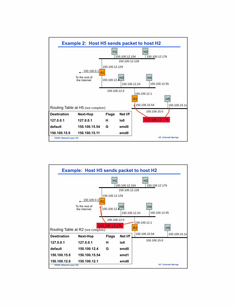
Example 2: Host H5 sends packet to host H2
R1
H1 H2
150.100.0.1
150.100.12.128150.100.12.176150.100.12.154
150.100.12.129
R1H3 H4
R2 H5
To the rest ofthe Internet
50 00 0
150.100.12.0
150.100.12.24 150.100.12.55
150.100.12.1
150.100.15.54 150.100.15.11
150.100.12.4
R ti T bl t H5 ( l )
CS422 Network Layer.123 UC. Colorado Springs
150.100.15.0Destination Next-Hop Flags Net I/F
127.0.0.1 127.0.0.1 H lo0
default 150.100.15.54 G emd0
150.100.15.0 150.100.15.11 emd0
Routing Table at H5 (not complete)
150.100.12.176
Example: Host H5 sends packet to host H2
H1 H2
150 100 0 1
150.100.12.128150.100.12.176150.100.12.154
150.100.12.129
R1H3 H4
R2 H5
To the rest ofthe Internet
150.100.0.1
150.100.12.0
150.100.12.24 150.100.12.55
150.100.12.1
150 100 15 54 150 100 15 11
150.100.12.4
Routing Table at R2 (not complete)150.100.12.176
CS422 Network Layer.124 UC. Colorado Springs
150.100.15.54
150.100.15.0
150.100.15.11Destination Next-Hop Flags Net I/F
127.0.0.1 127.0.0.1 H lo0
default 150.100.12.4 G emd0
150.100.15.0 150.100.15.54 emd1
150.100.12.0 150.100.12.1 emd0
Example: Host H5 sends packet to host H2
H1 H2
150 100 0 1
150.100.12.128150.100.12.176150.100.12.154
150.100.12.129 150.100.12.176
R1H3 H4
R2 H5
To the rest ofthe Internet
150.100.0.1
150.100.12.0
150.100.12.24 150.100.12.55
150.100.12.1
150 100 15 54 150 100 15 11
150.100.12.4
Routing Table at R1 (not complete)
CS422 Network Layer.125 UC. Colorado Springs
150.100.15.54
150.100.15.0
150.100.15.11Destination Next-Hop Flags Net I/F
127.0.0.1 127.0.0.1 H lo0
150.100.12.176 150.100.12.176 emd0
150.100.12.0 150.100.12.4 emd1
150.100.15.0 150.100.12.1 G emd1
° In the 1990, two problems became apparent• IP addresses were being exhausted• IP routing tables were growing very large
° IP Address Exhaustion• Class A, B, and C address structure inefficient
IP Address Problems
- Class B too large for most organizations - Class C too small- Rate of class B allocation implied exhaustion by 1994
° IP routing table size• Growth in number of networks in Internet reflected in # of table entries
- From 1991 to 1995, routing tables doubled in size every 10 months- Stress on router processing power and memory allocation
CS422 Network Layer.126 UC. Colorado Springs
° Short-term solution: ° Classless Inter-domain Routing (CIDR), RFC 1518° New allocation policy (RFC 2050)° Private IP Addresses set aside for intranets (NAT)° Long-term solution: IPv6 with much bigger address space
° A company is allocated the following four /24 networks. At some router, it is often true that all of the four networks use the same outgoing line. CIDR aggregation can be done to reduce the number of entry at the router.
Pre-CIDR: Network with range of 4 contiguous class C blocks requires 4 entries
CS422 Network Layer.127 UC. Colorado Springs
g g q
Post-CIDR: Network with range of 4 contiguous class C blocks requires 1 entry
Classless Inter-Domain Routing (CIDR)
° CIDR deals with Routing Table Explosion Problem• Networks represented by prefix and mask• Summarize a contiguous group of class C addresses using
variable-length mask, if all of them use the same outgoing line
° Solution: Route according to prefix of address, not class• Routing table entry has <IP address, network mask>• Example: 192.32.136.0/21• 11000000 00100000 10001000 00000001 min address• 11111111 11111111 11111--- -------- mask• 11000000 00100000 10001--- -------- IP prefix
CS422 Network Layer.128 UC. Colorado Springs
• 11000000 00100000 10001111 11111110 max address
Another CIDR Example
° Example: 150.158.16.0/20• IP Address (150.158.16.0) & mask length (20)• IP add = 10010110 10011110 00010000 00000000• Mask = 11111111 11111111 11110000 00000000• Mask = 11111111 11111111 11110000 00000000• Contains 16 Class C blocks:• From 10010110 10011110 00010000 00000000• i.e. 150.158.16.0• Up to 10010110 10011110 00011111 00000000• i.e. 150.158.31.0
CS422 Network Layer.129 UC. Colorado Springs
CIDR Example 3
° A router has the following CIDR entries in its routing table:
Address/mask Next hop128.56.24.0/22 Interface 0128.56.60.0/22 Interface 1default Router 2
A packet comes with IP address of 128.56.63.10. What does the router do?
CS422 Network Layer.130 UC. Colorado Springs
° Class A & B assigned only for clearly demonstrated need
° Consecutive blocks of class C assigned (up to 64 blocks)
Address Requirement
Address Allocation
New Address Allocation Policy
g ( p )• All IP addresses in the range
have a common prefix, and every address with that prefix is within the range
• Arbitrary prefix length for network ID improves efficiency
° Lower half of class C space
< 256 1 Class C
256<,<512 2 Class C
512<,<1024 4 Class C
1024<,<2048 8 Class C
2048<,<4096 16 Class C
CS422 Network Layer.131 UC. Colorado Springs
Lower half of class C space assigned to regional authorities• More hierarchical allocation of
addresses• Service provider to customer
,
4096<,<8192 32 Class C
8192<,<16384 64 Class C
0000 0001 0010 0011
0100 0101 0110 0111
R1 R2
1
2 5
4
3
(a)
Recap: Hierarchical Routing & Table Efficiency
1100 1101 1110 1111
1000 1001 1010 1011
00 101 310 211 3
00 301 410 311 5
0000 0111 1010 1101
0001 0100 1011 1110
1 4
(b)
CS422 Network Layer.132 UC. Colorado Springs
1101 1110
0011 0101 1000 1111
0011 0110 1001 1100
R1 R22 5
3
0000 10111 1 1010 1… …
0001 40100 41011 4… …
CIDR Allocation Principles (RFC 1518-1520)
° IP address assignment reflects physical topology of network
° Network topology follows continental/national boundaries • IP addresses should be assigned on this basis
° Transit routing domains (TRDs) have unique IP prefix• carry traffic between routing domains• interconnected non-hierarchically, cross national
boundaries• Most routing domains single-homed: attached to a single
TRD• Such domains assigned addresses with TRD's IP prefix
CS422 Network Layer.133 UC. Colorado Springs
• Such domains assigned addresses with TRD's IP prefix• All of the addresses attached to a TRD aggregated into 1
table entry
° Implementation primarily through BGPv4 (RFC 1520)
Longest Prefix Match
° CIDR impacts routing & forwarding
° Routing tables and protocols must carry IP address and mask
° Multiple entries may match a given IP destination addressp y g
° Example: perform CIDR on the following three /24 IP addresses (but 128.56.24.0/24 to a different port)
• 128.56.25.0/24;• 128.56.26.0/24;• 128.56.27.0/24;• What if a packet with dest IP address 128 56 24 0 comes?
CS422 Network Layer.134 UC. Colorado Springs
What if a packet with dest. IP address 128.56.24.0 comes?
° Packet must be routed using the more specific route, that is, the longest prefix match
° Several fast longest-prefix matching algorithms are available
NAT – Network Address Translation° What is the problem of the on-the-fly IP address assignment?
° NAT: pubic IP addresses and private IP addresses
CS422 Network Layer.135 UC. Colorado Springs
Placement and operation of a NAT box (supporting class-B size).
How to translate when the reply comes back? What are its problems?
Private IP Addresses
° Specific ranges of IP addresses set aside for use in private networks (RFC 1918)
° Use restricted to private internets; routers in public Internet discard packets with these addressespackets with these addresses
° Range 1: 10.0.0.0 to 10.255.255.255
° Range 2: 172.16.0.0 to 172.31.255.255
° Range 3: 192.168.0.0 to 192.168.255.255
° Network Address Translation (NAT) used to convert between private & global IP addresses
CS422 Network Layer.136 UC. Colorado Springs
global IP addresses• Able to support about 64K interval distinct IP addresses
Internet Control Message Protocol
° ICMP reports unexpected operations and test Internet
5-61
CS422 Network Layer.137 UC. Colorado Springs
The principal ICMP message types.
ARP– The Address Resolution Protocol° How to map IP addresses to data link layer addresses since
data link layer hardware does not understand IP addresses?
° Simplicity: a configuration file -> ARP using broadcast
CS422 Network Layer.138 UC. Colorado Springs
Three interconnected /24 networks: two Ethernets and an FDDI ring.
How to make ARP work more efficiently? Caching
OSPF – The Interior Gateway Routing Protocol
° How to route packets within an AS (autonomous system)?• RIP -> link state routing > OSPF (open shortest path first)
° What are important requirements for OSPF?• Openness• Openness• Variety of distance metrics• Dynamic• TOS support• Load balancing• Support hierarchical routing• security
CS422 Network Layer.139 UC. Colorado Springs
• security
BGP – The Exterior Gateway Routing Protocol
What OSPF concerns most?
What OSPF does not care but BGP does?
Efficiency!
Politics?
CS422 Network Layer.140 UC. Colorado Springs
(a) A set of BGP routers. (b) Information sent to F.
IPv6° Longer address field:
• 128 bits can support up to 3.4 x 1038 hosts
° Simplified header format: • Simpler format to speed up processing of each header• Simpler format to speed up processing of each header• All fields are of fixed size• IPv4 vs IPv6 fields:
- Replaced: – Datagram length by Payload length– Protocol type by Next header– TTL by Hop limit– TOS by traffic class
- New: Flow label
Other IPv6 Features
° Flexible support for options (Next header): more efficient and flexible options encoded in optional extension headers (immediate follow )
° Flow label capability: “flow label” to identify a packet flow that requires a certain QoSrequires a certain QoS
° Security: built-in authentication and confidentiality
° Large packets: supports payloads that are longer than 64 K bytes, called jumbo payloads.
° Fragmentation at source only: source should check the minimum MTU along the path
CS422 Network Layer.142 UC. Colorado Springs
MTU along the path
° No checksum field: removed to reduce packet processing time in a router
IPv6 Header Format
Version Traffic Class Flow Label
Payload Length Next Header Hop Limit
Source Address
0 4 12 16 24 31
° Version field same size, same location
Source Address
Destination Address
CS422 Network Layer.143 UC. Colorado Springs
° Traffic class to support differentiated services
° Flow: sequence of packets from particular source to particular destination for which source requires special handling
IPv6 Basic Header Format
Version Traffic Class Flow Label
Payload Length Next Header Hop Limit
0 4 12 16 24 31
Source Address
Destination Address
CS422 Network Layer.144 UC. Colorado Springs
° Payload length: length of data excluding header, up to 65535 B
° Next header: type of extension header that follows basic header
° Hop limit: # hops packet can travel before being dropped by a router
Why fragmentation at source only? Relieving load at routers.
Extension Headers
0 8 16 24 31
° Allows an arbitrary number of extension headers be placed between the basic header and the payload (the extension headers are chained by the next header field)
° Large Packet: payload>64K (extension header)
Next header 0 194 Opt len = 4
Jumbo payload length
0 8 16 24 31
Fragmentation: at source only (extension header)Source performs “path MTU discovery” (a fragment extension header for each packet fragment)
CS422 Network Layer.145 UC. Colorado Springs
extension header for each packet fragment)
Next header Reserved Fragment offset Res M
Identification
0 8 16 29 31
Extension Headers
° IPv6 supports Source Routing
Reserved Strict/loose bit mask
0 8 16 24 31
Next header Header length Routing type = 0 Segment left
Address 1
Address 2
. . .
CS422 Network Layer.146 UC. Colorado Springs
Address 24
IPv6 Addressing° Address Categories
• Unicast: single network interface• Multicast: group of network interfaces, typically at different
locations. Packet sent to all.• Anycast: group of network interfaces Packet sent to only oneAnycast: group of network interfaces. Packet sent to only one
interface in group, e.g. nearest.
° Hexadecimal notation• Groups of 16 bits represented by 4 hex digits• Separated by colons