75
CSC 581 Communication Networks II Chapter 8b: Transport Layer Dr. Cheer-Sun Yang
| Date post: | 02-Jan-2016 |
| Category: |
Documents |
| Upload: | arabella-riley |
| View: | 220 times |
| Download: | 2 times |

CSC 581Communication Networks II
Chapter 8b: Transport Layer
Dr. Cheer-Sun Yang
2
TOPICS
• OSI Transport Services, design, protocols
• Example Protocols: TCP, UDP
• Client-Server Model and Socket Programming

3
Reliable Sequencing Network Service
• Assume arbitrary length message• Assume virtually 100% reliable delivery by
network service– e.g. reliable packet switched network using X.25
– e.g. frame relay using LAPF control protocol
– e.g. IEEE 802.3 using connection oriented LLC service
• Transport service is end to end protocol between two systems on same network

4
Reliable Sequencing Network Service
• It is important because IP or other network layer protocols do no guarantee reliable service. Transport protocols must provide acknowledgements and timers to make sure that all of a user’s data are sent and received.

5
TCP is not the OSI Transport Layer Protocol
• TCP is designed and developed by the DoD to run on top of IP for providing connection-oriented transport layer services.
• OSI transport layer protocol is a generic redesign of transport layer protocol which includes more functions than TCP.

6
OSI vs. TCP
• OSI transport services include a more complete set of services
• TCP is not identical to OSI transport protocol in terms of the PDU format, and even some terms. For example, TCP calls its PDU a segment; OSI calls its PDU a TPDU; TCP identifies its application using a port number, OSI uses a Transport Service Access Point(TSAP). We will summarize the comparison at the end of this unit of slides.

7
Issues in OSI Transport Protocols
• Establishing a Connection • Releasing a connection• Addressing• Quality of Service (QoS) • Multiplexing • Flow Control and Buffering• Crash Recovery

8
Addressing• Target user specified by:
– User identification: Transport Service Access Point (TSAP)
– Machine identification: Network layer address, such as IP address, identifies a host

9
Finding Addresses
• Four methods– Know address ahead of time
• e.g. collection of network device stats
– Well known addresses– Name server– Sending process request to well known address
10
QoS
• Another way to look at the transport service is to regard its primary function as enhancing the QoS provided by the network layer.
• If the network layer is impeccable, the transport layer has an easy job.
• If the network layer is unreliable, the transport layer has to bridge the gap between what the user wants and the network layer provides.

11
QoS
• What is QoS? It is characterized by a list of QoS parameters which can be negotiated at the connection establishment time.
• It is specified by users at the user layer.
• It is up to the transport layer to examine them and determine whether or not it can provide the required service.

12
QoS Parameters
• Connection establishment delay• Connection establishment failure probability • Throughput• Transit delay• Residual error ratio• Protection• Priority• Resilience

13
Comparison with Data Link Layer
• Similarity: both layers are focusing on how information is exchanged between two entities
• Difference:Data link layer defines communications between stations with a physical connection, whereas transport layer protocols define communications between sites with a logical connection.
• Two kinds of transport layer protocols: connection-oriented and connection-less.
14
Transport Layer Characteristics
• Reliable: flow control and error recovery are provided
• Two kinds: connection-oriented or connection-less• Example: Transmission Control Protocol(TCP),
User Datagram Protocol(UDP)• Transport layer is the lowest layer which provides
end-to-end services. The lower three protocols defines how network operates.
15
Transport Layer Functions• Logical connection establishment – the transport
layer provides the “connection” the user perceives. • A user can log on to computers at remote sites,
giving them the impression that they are connected.
• But the connection is not a physical one as exists when connecting wires or making phone calls (using circuit switching).
16
Transport Layer Functions(cont’d)
• It is similar to a secretary whose function is to place calls in behalf of an executive. The secretary gets the executive’s request, makes the call, and reaches the desired person, thus making the connection.
• The executive then proceeds to have the conversation independent of the trouble that the secretary may have had in finding the desired person.
17
Transport Layer Functions(cont’d)
• The connection management defines the rules that allow two users to begin talking with one another as if they were connected directly. The function of defining and setting up the connection is referred to as handshaking.
18
Transport Layer Functions(cont’d)
• Graceful connection termination
• The secretary may have to finish the connection by taking down some important information such as client’s address, checking the executive’s schedule for making a future appointment.
• There are other functions.

19
Connection Oriented Transport Protocol Mechanisms
• Example: Transmission Control Protocol(TCP)

20
Connection-less Transport Protocol Mechanisms
• No connection-establishment
• Datagram delivery
• User Datagram Protocol(UDP)
21
Motivations
• Why do we still need transport layer running on top of network layer?– They have similar connection-oriented and
connection-less services.– They both provide addressing and flow-control
22
The answers are…
• What happens if the network layer provides connection-oriented but unreliable service? Suppose that it frequently loses packets? What happens if routers crash all the time?
• Users have no control over the subnet, so they cannot solve the problem of poor service by using better routers or putting more error handling in the data link layer.
• So another layer is added to provide better quality of service(QoS).

23
Transport Layer Functions
• Establishment of connectionless or connection-oriented communication
• Addressing• Flow Control (transport layer)• Error detection (transport layer)• Interface with upper layers • Multiplexing• Quality of Service (QoS) In general, a transport layer protocol must providereliable communications between end users.

Copyright 2000 McGraw-Hill Leon-Garcia and Widjaja Communication Networks
24
0 0 0 0 0 0 0 0 Protocol = 17 UDP Length
Source IP Address
Destination IP Address
0 8 16 31
Figure 8.17
Copyright 2000 McGraw-Hill Leon-Garcia and Widjaja Communication Networks
25
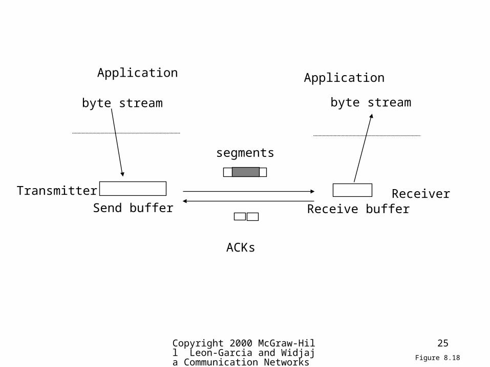
byte stream
Send buffer
segments
Receive buffer
byte stream
Application Application
ACKs
Transmitter Receiver
Figure 8.18

Copyright 2000 McGraw-Hill Leon-Garcia and Widjaja Communication Networks
26
Transmitter Receiver
Receive Window
Slast Slast+Ws-1
...
Send Window
Srecent
Octetstransmittedand ACKed
Rnext
... ...
Slast+Wa-1 RlastRlast+WR+1
Slast oldest unacknowledged octetSrecent highest-numbered transmitted octetSlast+Wa-1 highest-numbered octet that can be transmittedSlast+Ws-1 highest-numbered octet that can be accepted from the application
Rlast highest-numbered octet not yet read by the applicationRnext next expected octetRnew highest numbered octet receivedcorrectlyRlast+WR-1 highest-numbered octet that can be accommodated in receive buffer
Rnew
Figure 8.19

27
TCP Header

Copyright 2000 McGraw-Hill Leon-Garcia and Widjaja Communication Networks
28
Source Port Destination Port
Sequence Number
Acknowledgement Number
Checksum Urgent Pointer
Options Padding
0 4 10 16 24 31
URG
ACK
PSH
RST
SYN
FIN
HeaderLength Reserved Window Size
Data
Figure 8.20
Copyright 2000 McGraw-Hill Leon-Garcia and Widjaja Communication Networks
29
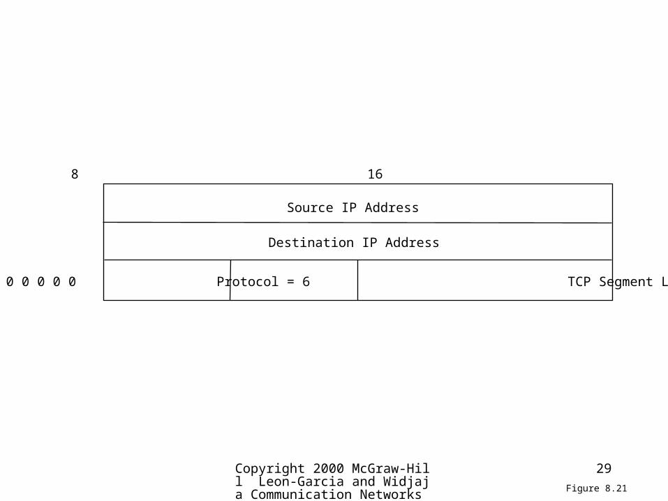
0 0 0 0 0 0 0 0 Protocol = 6 TCP Segment Length
Source IP Address
Destination IP Address
0 8 16 31
Figure 8.21

30
TCP Mechanisms (1)
• Connection establishment– Three way handshake– Between pairs of ports– One port can connect to multiple destinations

31
TCP Mechanisms (2)
• Data transfer– Logical stream of octets– Octets numbered modulo 223
– Flow control by credit allocation of number of octets
– Data buffered at transmitter and receiver– Congestion control
32
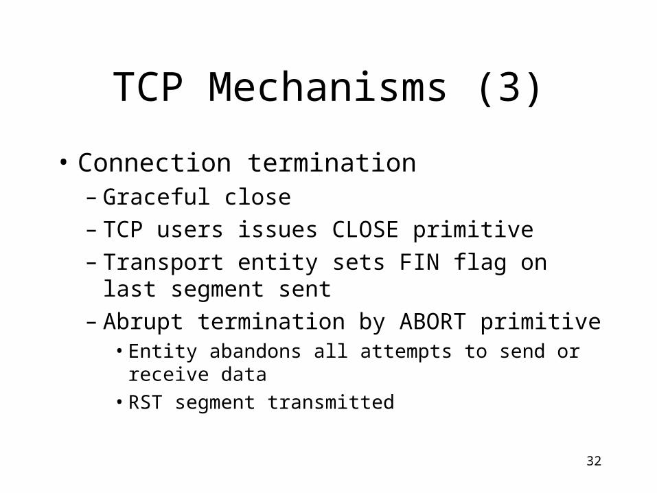
TCP Mechanisms (3)
• Connection termination– Graceful close– TCP users issues CLOSE primitive– Transport entity sets FIN flag on last segment
sent– Abrupt termination by ABORT primitive
• Entity abandons all attempts to send or receive data
• RST segment transmitted

Copyright 2000 McGraw-Hill Leon-Garcia and Widjaja Communication Networks
33
Host A Host B
SYN, Seq_no = x
SYN, Seq_no = y, ACK, Ack_no = x+1
Seq_no = x+1, ACK, Ack_no = y+1
Figure 8.22

Copyright 2000 McGraw-Hill Leon-Garcia and Widjaja Communication Networks
34
Host A Host B
SYN, Seq_no = n
SYN, Seq_no = n, ACK, Ack_no = n+1
Seq_no = n+1, ACK, Ack_no = n+1
Delayed segment withSeq_no = n+2will be accepted
Figure 8.23
Copyright 2000 McGraw-Hill Leon-Garcia and Widjaja Communication Networks
35
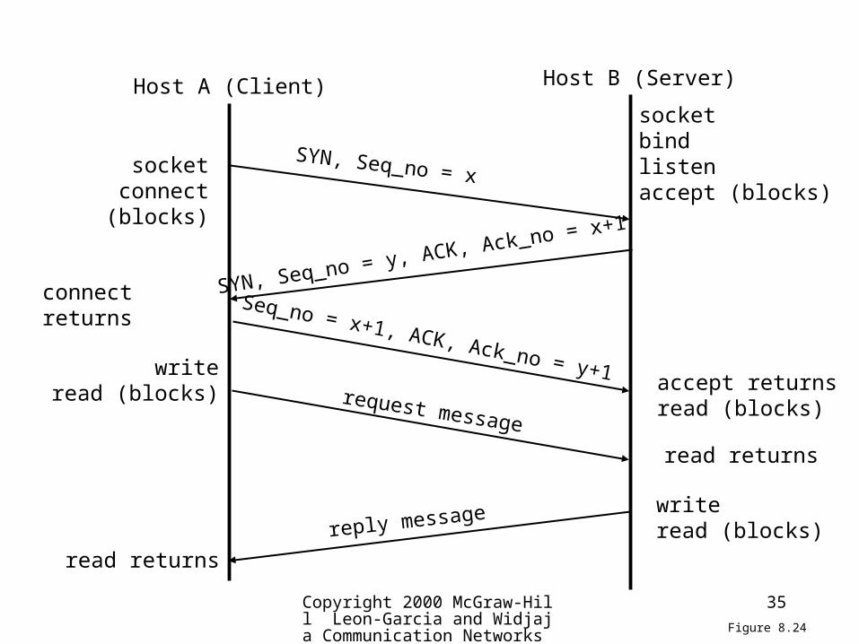
Host A (Client) Host B (Server)
SYN, Seq_no = x
SYN, Seq_no = y, ACK, Ack_no = x+1
Seq_no = x+1, ACK, Ack_no = y+1
socketbindlistenaccept (blocks)
socketconnect (blocks)
connect returns
accept returnsread (blocks)
writeread (blocks)
read returns
writeread (blocks)
read returns
request message
reply message
Figure 8.24

Copyright 2000 McGraw-Hill Leon-Garcia and Widjaja Communication Networks
36
Host A Host B
Seq_no = 2000, Ack_no = 1, Win = 1024, Data = 2000-3023
Seq_no = 1, Ack_no = 4048, Win = 512, Data = 1-128
Seq_no = 3024, Ack_no = 1, Win = 1024, Data = 3024-4047
Seq_no = 4048, Ack_no = 129, Win = 1024, Data = 4048-4559
t1
t2
t3
t4
Seq_no = 1, Ack_no = 2000, Win = 2048, No Data t0
Figure 8.25

Copyright 2000 McGraw-Hill Leon-Garcia and Widjaja Communication Networks
37
Data
TCP Header
20 bytes of TCP header
20 bytes of IP header
IP Header
Figure 8.26

Copyright 2000 McGraw-Hill Leon-Garcia and Widjaja Communication Networks
38
FIN, seq = 5086
ACK = 5087
Data, seq. = 303, ACK = 5087Deliver 150 bytes
FIN, seq. =453, ACK = 5087
ACK = 454
Host A Host B
ACK = 453
Figure 8.27

Copyright 2000 McGraw-Hill Leon-Garcia and Widjaja Communication Networks
39
CLOSED
LISTEN
SYN_RCVD
ESTABLISHED
CLOSING
TIME_WAIT
SYN_SENT
FIN_WAIT_1
CLOSE_WAIT
LAST_ACK
FIN_WAIT_2
active open,create TCB
send SYN
passive open,create TCB
send SYN
receive SYN,
send SYN, ACK
receive
RST
receiveACK receive SYN, ACK,send ACKapplic.
close,sendFIN
applic. clo
se,
send FIN
receive FIN,send ACK
receive FINsend ACK
receive FIN, ACK
send ACKreceive
ACK
receive FINsend ACK
receiveACK
applic. closesend FIN
receiveACK
applic. closeor timeout,delete TCB
2MSL timeoutdelete TCB
receive SYN,send ACK
applic.close
Figure 8.28
40
Flow Control
• Credit Mechanism
• A credit, stored in the segment’s window field, specifies the maximum number of bytes the entity (node) sending this segment can receive and buffer from the other entity (node).

41
Congestion Control
• There are problems that the flow control mechanism cannot solve.
• Assume that the previous discussion showed that the window sizes (credits) were adjusted based only on what A or B can handle. It didn’t take into account what might be in between.
• What happens that A and B both are connected to others with T-1 links but use a link capable to transmit 64 kbps between A and B?
42
Congestion Window
• Due to Jacobson [1988]- Jacobson’s algorithm
• TCP is enhanced to allow a sending entity to respond to congestion links and to alter the number of segments it can send.

43
Congestion Window
• We will focus on the transmission from A to B.• A maintains a congestion window that specifies
the number of bytes it thinks it can send without causing or adding to congestion.
• If the congestion window’s capacity is larger than A’s credit then A will still not send more than the credit allows.
• Otherwise, A uses the congestion window’s value to determine how many segments to send.
44
Congestion Window
• How can A determine when congestion exists? – Timeout mechanism
• How does A respond to congestion? – reduce the size of the congestion window by half; resend; if timeout occurs again, the window size is reduced by half again.
45
Congestion Window
• If the congestion is alleviated, A will increase the congestion window size and recalculate the sending window size.
• Consequently, A will reduce the congestion window much more quickly than it will increase it.
• A remaining question…

46
Congestion Window
• How is the initial congestion window size determined?
• It is similar to the recovery procedure after congestion.

47
Initial Value
• A will reduce the congestion window much more quickly than it will increase it.
• The startup procedure is called a slow start.

48
Window Management• Slow start
– Actual window= MIN[credit, congested window]– Start connection with congested window size=1– Increment congested window(cwnd) at each ACK, to some max
• Dynamic windows sizing on congestion– When a timeout occurs– Set slow start threshold to half current congestion window
• ssthresh=cwnd/2
– Set cwnd = 1 and slow start until cwnd=ssthresh• Increasing cwnd by 1 for every ACK
– For cwnd >=ssthresh, increase cwnd by 1 for each RTT

49
Congestion Control
• RFC 1122, Requirements for Internet hosts• Retransmission timer management
– To control a lost or discard segment, TCP employs a retransmission timer which handles the retransmission time, the waiting time for an ACK of a segment.
– For each connection, TCP maintains a variable, RTT, that is the best estimate of the current round trip time to the destination in question. When a segment is sent, a timer is started.
50
Congestion Control
• When a timer is created, two situations can occur:– If an ACK is received for this particular
segment before the timer goes off, the timer is destroyed.
– If the timer goes off before the ACK is received, the segment is retransmitted and the timer is reset.

51
Calculation of the Retransmission Time
• Retransmission = 2 * RTT
• RTT: estimated Round-Trip Time
52
Calculation of RTT
• RTT = * previous RTT + (1 - ) * current RTT
is usually set to 90%.

53
Karn’s Algorithm
• Suppose that a segment is not acknowledged during the retransmission period and it is therefore retransmitted. When the sending TCP receives an ACK for this segment, it does not know if the ACK is for the original segment or for the retransmitted one. The value of the new RTT therefore must be calculated based on the departure of the segment.

54
Karn’s Algorithm
• Do not consider the RTT of a retransmitted segment in the calculation of the new RTT.
• Do not update the value of the RTT until you send a segment and receive an ACK without the need for retransmission.

55
Karn’s Algorithm
• If a segment is re-transmitted, the ACK arriving may be:– For the first copy of the segment
• RTT longer than expected
– For second copy
• No way to tell• Do not measure RTT for re-transmitted segments• Calculate backoff when re-transmission occurs• Use backoff RTO until ACK arrives for segment
that has not been re-transmitted

56
Conceptual TCP Primitives
• Open - request
• Send - request
• Deliver - indication
• Accept - indication
• Terminate – confirm
• Etc.
57
Send
• If no push or close TCP entity transmits at its own convenience
• Data buffered at transmit buffer
• May construct segment per data batch
• May wait for certain amount of data
58
Deliver
• In absence of push, deliver data at own convenience
• May deliver as each in order segment received
• May buffer data from more than one segment
59
Accept
• Segments may arrive out of order
• In order– Only accept segments in order– Discard out of order segments
• In windows– Accept all segments within receive window

60
Retransmit
• TCP maintains queue of segments transmitted but not acknowledged
• TCP will retransmit if not ACKed in given time– First only– Batch– Individual
61
Acknowledgement
• Immediate
• Cumulative

62
UDP
• User datagram protocol (UDP) runs on top of IP.• RFC 768• Connectionless service for application level
procedures– Unreliable– Delivery and duplication control not guaranteed
• Reduced overhead• There is no formal mechanism for acknowledging
errors or a provision for flow control or segment sequencing.

63
UDP Uses
• Inward data collection
• Outward data dissemination
• Request-Response
• Real time application

64
UDP Header

65
OSI vs. TCP
• Segment Types
• Important Data
• Graceful Termination
• Piggyback acknowledgement
• Sequencing
• Flow Control
66
Socket Programming
• Sockets
• Client/Server Model
• Socket Data Structure
• Socket Commands
• Examples: Client Program, Server Program

67
Sockets
• A socket is a UNIX construct and is the basis for UNIX networking services.
• A socket is similar to an envelop in which information can be stored.
68

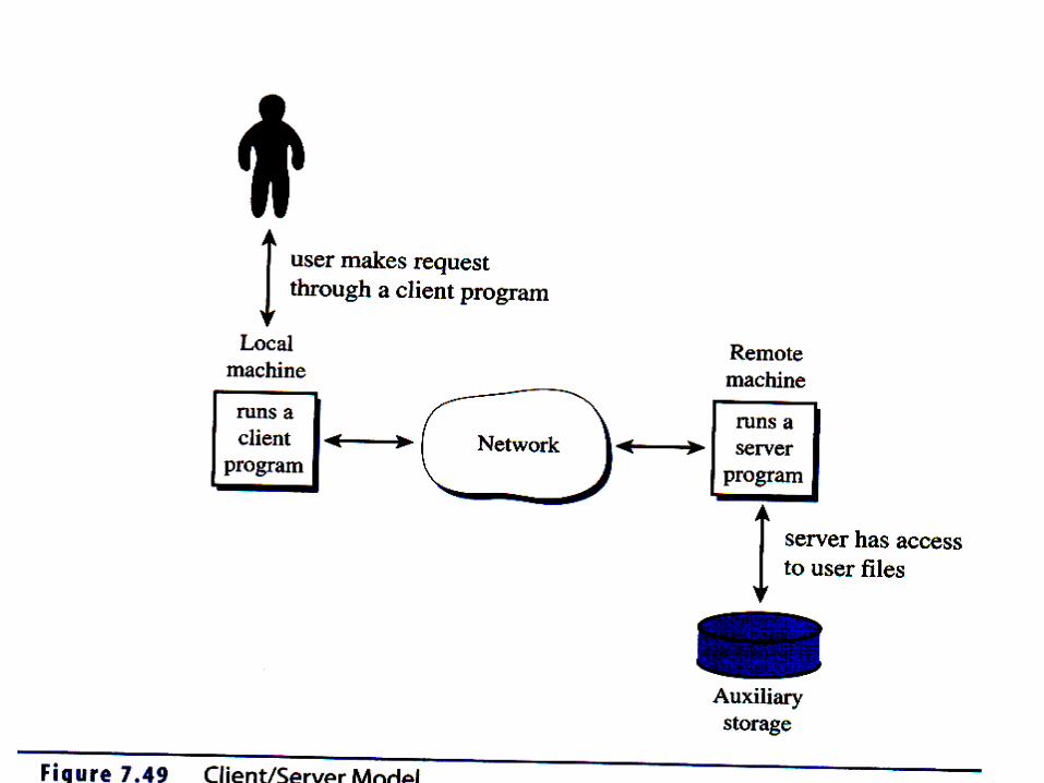
69
Client/Server ModelAn example of file transfer:• User requests a file.• Client sends request to the server on behalf of the user.• Server receives a request from a client and analyzes it.• Server copies a file from its auxiliary storage.• Server transmits contents of the file back to the client.• Client gets files’s contents from the server and make it
accessible to the user.
70
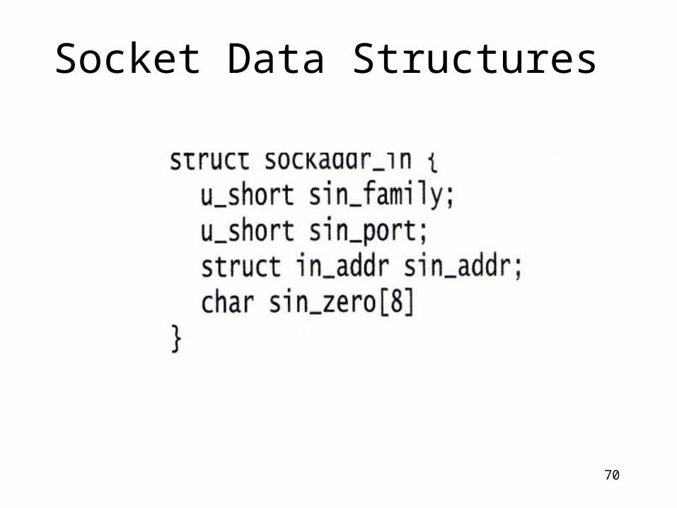
Socket Data Structures

71
Socket Data Structures

72
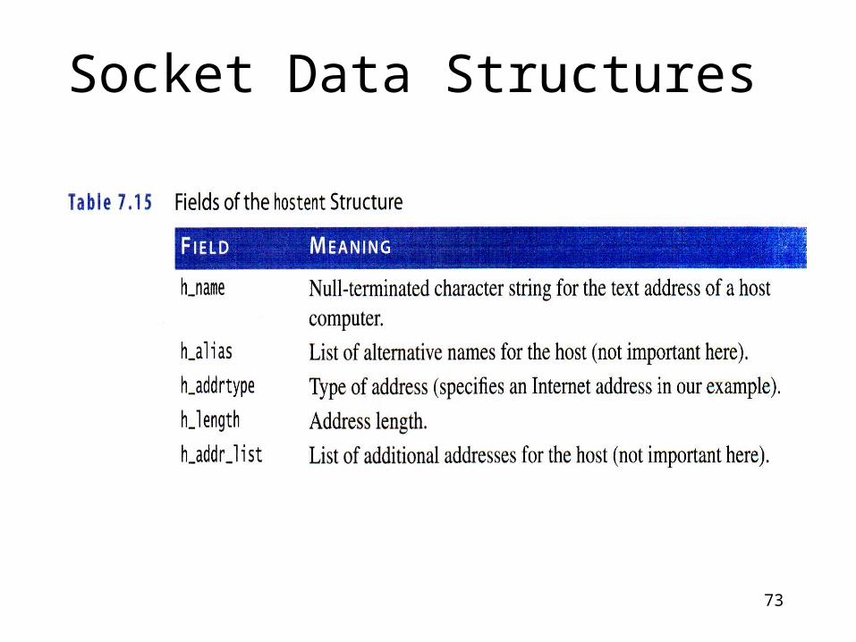
Socket Data Structures
73
Socket Data Structures
74
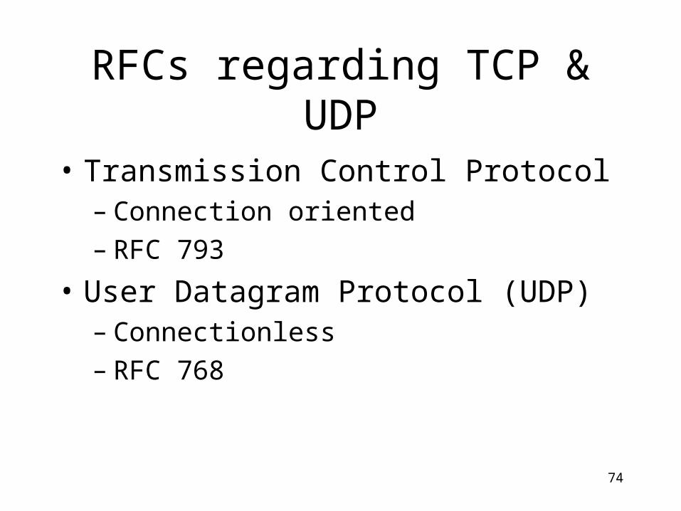
RFCs regarding TCP & UDP
• Transmission Control Protocol– Connection oriented– RFC 793
• User Datagram Protocol (UDP)– Connectionless– RFC 768

75
Suggested Reading
• Sections 8.4 (UDP), 8.5 (TCP)
• RFC793 (TCP) 768 (UDP) 1112 (Host Extensions for Multicasting)


