64
Madam Raini Hassan Office: C5 - 23, Level 5, KICT Building Department: Computer Science Emails: [email protected], [email protected] 1
| Date post: | 15-Jul-2015 |
| Category: |
Education |
| Upload: | pocong-makenon |
| View: | 107 times |
| Download: | 1 times |

Madam Raini Hassan
Office: C5 - 23, Level 5, KICT Building
Department: Computer Science
Emails: [email protected], [email protected] 1

Du’a for Study
Semester II 2014/2015 2

LECTURE 07
External Memory (Chapter 6)

Outline
• Magnetic Disk
Magnetic Read and Write
Mechanisms
Data Organization and
Formatting
Physical Characteristics
Disk Performance
Parameters
• RAID
RAID Level 0 to 6
• Solid State Drives
Flash Memory
SSD Compared to HDD
SSD Organization
Practical Issues
• Optical Memory
Compact Disk
Digital Versatile Disk
High-Definition Optical
Disks
Semester II 2014/2015 4

Magnetic Disk
• A disk is a circular platter constructed of nonmagnetic material, called
the substrate, coated with a magnetizable material
– Traditionally the substrate has been an aluminium or aluminium alloy material
– Recently glass substrates have been introduced
• Benefits of the glass substrate:
– Improvement in the uniformity of the magnetic film surface to increase disk
reliability
– A significant reduction in overall surface defects to help reduce read-write errors
– Ability to support lower fly heights
– Better stiffness to reduce disk dynamics
– Greater ability to withstand shock and damage
Semester II 2014/2015 5

MAGNETIC READ AND WRITE
MECHANISMS Data are recorded on and later retrieved from the disk via a conducting coil named the head
•In many systems there are two heads, a read head and a write head
•During a read or write operation the head is stationary while the platter rotates beneath it
The write mechanism exploits the fact that
electricity flowing through a coil produces a magnetic
field
Electric pulses are sent to the write head and the resulting magnetic
patterns are recorded on the surface below, with different
patterns for positive and negative currents
The write head itself is made of easily magnetizable material
and is in the shape of a rectangular doughnut with a gap along one side and a few
turns of conducting wire along the opposite side
An electric current in the wire induces a magnetic
field across the gap, which in turn magnetizes
a small area of the recording medium
Reversing the direction of the current reverses the
direction of the magnetization on the
recording medium Semester II 2014/2015 6

Inductive Write/Magnetoresistive Read Head
Semester II 2014/2015 7

8
Data Organization and Formatting
• Concentric set of rings called tracks
– There are gaps between adjacent tracks
– This prevents or minimizes errors due to misalignment of the head or inference of magnetic field.
– Same number of bits per track (variable packing density)
• Tracks divided into sectors
• Minimum block size is one sector
• May have more than one sector per block
Semester II 2014/2015

9
Disk Data Layout Concentric set of rings
called tracks
Tracks divided into sectors

10
Disk Velocity • Bit near centre of rotating disk passes fixed point
slower than bit on outside of disk.
• Therefore some way must be found to compensate the variation is speed so that the head can read all the bits at the same rate.
• That particular way: Increase spacing between bits in different tracks.
– Constant angular velocity (CAV) – The information then can be scanned at the same rate by rotating the disk at a fixed speed.
• Rotate disk at constant angular velocity (CAV)
– Gives pie shaped sectors and concentric tracks
– Move head to given track and wait for given sector
Semester II 2014/2015

11
Disk Layout Methods Diagram: CAV
• Increase spacing between bits
in different tracks.
– The information then can be
scanned at the same rate by
rotating the disk at a fixed
speed.
• Adv: Individual tracks and
sectors addressable
• Disadv: Waste of space on
outer tracks
– Lower data density Semester II 2014/2015

12
Disk Layout Methods Diagram: MZR
• Use zones to increase
capacity
– Each zone has fixed bits
per track
– More complex circuitry
Semester II 2014/2015
13
Finding Sectors: Formatting
• Must be able to identify start of track and sector
• Format disk
– The disk is formatted with some extra data used only by the
disk drive and not accessible to user
– Marks tracks and sectors.
Semester II 2014/2015

Finding Sectors: Formatting –
Example (Winchester Disk
Format - Seagate ST506)
Semester II 2014/2015 14

15
Finding Sectors: Formatting –
Example (Winchester Disk Format) • In this case, each track contains 30 fixed-length sectors of
600 bytes each.
• Each sector holds 512 bytes of data plus control information useful to the disk controller.
• The ID field is a unique identifier or address used to locate a particular sector.
• The SYNCH byte is a special bit pattern that delimits the beginning of the field.
• The track number identifies a track on a surface.
• The head number identifies a head, because this head has multiple surfaces.
• The ID and data field each contain an error-detecting code.
Semester II 2014/2015

Table 6.1
Physical Characteristics
of Disk Systems
Table 6.1 Physical Characteristics of Disk Systems Semester II 2014/2015 16

17
Head Motion
• Fixed head
– One read-write head per track
– Heads are mounted on a fixed ridged arm that extends across
all tracks
• Movable head
– One read-write head
– Head is mounted on an arm
– The arm can be extended or retracted
Semester II 2014/2015

18
Disk Portability
• Removable disk
– Can be removed and replaced with another disk
– Advantages:
• Unlimited amounts of data are available with a limited number of
disk systems
• A disk may be moved from one computer system to another
– Floppy disks and ZIP cartridge disks are examples of
removable disks
• Non-removable disk – Permanently mounted in the disk drive
– The hard disk in a personal computer is a non-removable disk
Semester II 2014/2015

19
Disk Portability - Examples
Floppy
ZIP
Semester II 2014/2015

20
Sides
• For most disks, the magnetizable coating is applied to
both sides of the platter, referred to as double-sided.
• Some less expensive disk systems use single-sided disks
Semester II 2014/2015

21
Platters
• One head per side
• Heads are joined and aligned
• Aligned tracks on each platter form cylinders
• Data is striped by cylinder
– reduces head movement
– Increases speed (transfer rate)
Semester II 2014/2015

22
Multiple Platters
For most disks, the magnetizable
coating is applied to both sides of
the platter, referred to as double-
sided.
Heads are joined and aligned
Semester II 2014/2015

23
Cylinders
Aligned tracks on
each platter form
cylinders
- Data is striped by cylinder
-> reduces head movement
-> Increases speed (transfer rate)
Semester II 2014/2015

24
Head Mechanisms
• The head must generate or sense an electromagnetic
field of sufficient magnitude to write and read properly.
• The narrower the head, the closer it must be to the
platter surface to function
– A narrower head means narrower tracks and therefore greater
data density
• The closer the head is to the disk the greater the risk of
error from impurities or imperfections
Semester II 2014/2015

25
Head Mechanisms: Fixed Gap
• Traditionally, the read-write positioned at a fixed
distance above the platter, allowing an air gap.
Semester II 2014/2015
26
Head Mechanisms: Contact (Floppy)
• A head mechanism that actually comes into physical contact with the medium during a read or write operation.
• 8”, 5.25”, 3.5”
• Small capacity – Up to 1.44Mbyte (2.88M never popular)
• Slow
• Universal
• Cheap
• Obsolete?
Semester II 2014/2015

27
Head Mechanisms: Aerodynamic
Gap (Winchester)
• Used in sealed drive assemblies that are almost free of
contaminants
• Designed to operate closer to the disk’s surface than
conventional rigid disk heads, thus allowing greater data
density
• Is actually an aerodynamic foil that rests lightly on the
platter’s surface when the disk is motionless
– The air pressure generated by a spinning disk is enough to
make the foil rise above the surface
Semester II 2014/2015

28
Disk Performance Parameters
• The actual details of disk I/O operation depend on the
computer system, the operating system, and the nature
of the I/O channel and disk controller hardware.
Semester II 2014/2015

Typical Hard Disk Parameters
Table 6.2 Typical Hard Disk Drive Parameters 29

Disk Performance Parameters • When the disk drive is operating the disk is rotating at
constant speed
• To read or write the head must be positioned at the
desired track and at the beginning of the desired sector
on the track
– Track selection involves moving the head in a movable-head
system or electronically selecting one head on a fixed-head
system
– Once the track is selected, the disk controller waits until the
appropriate sector rotates to line up with the head
Semester II 2014/2015 30

Disk Performance Parameters • Seek time
– On a movable–head system, the time it takes to position the head at the
track
• Rotational delay (rotational latency)
– The time it takes for the beginning of the sector to reach the head
• Access time
– The sum of the seek time and the rotational delay
– The time it takes to get into position to read or write
• Transfer time
– Once the head is in position, the read or write operation is then performed
as the sector moves under the head
– This is the data transfer portion of the operation
Semester II 2014/2015 31

RAID
• Consists of 7 levels (0 to 6).
• Use when there are instances where the
single hard disk cannot fulfill the
requirement of the business organizations
with regard to capacity, performance and
quality.
• Levels do not imply a hierarchical
relationship but designate different design
architectures that share three common
characteristics:
1) Set of physical disk drives viewed by the operating
system as a single logical drive
2) Data are distributed across the physical drives of an
array in a scheme known as striping
3) Redundant disk capacity is used to store parity
information, which guarantees data recoverability in
case of a disk failure
Redundant Array of
Independent Disks
32

N = number of data disks; m proportional to log N
Table 6.3 RAID Levels
33

RAID Levels
0, 1, 2
Semester II 2014/2015 34

RAID
Levels
3, 4, 5, 6
35

36
RAID 0
• Has the lowest cost of any RAID organization because it does not employ
redundancy at all.
• Data striped across all disks
• It offers the best performance but no fault-tolerance.
• For applications in which performance and capacity are primary concerns, and low
cost is more important than reliability
Semester II 2014/2015

37
RAID 1 • Redundancy achieved through mirrored disks
• Data is striped across disks
• Consists of at least 2 drives that duplicate the storage of data.
• Whenever data is written to a disk the same data is also written to a redundant disk,
so that there are always 2 copies of information.
• Write to both, read from either.
• RAID 1 can also be implemented without data striping, although this is less
common
Semester II 2014/2015

38
RAID 2 • Makes use of a parallel access technique
• In a parallel access array all member disks participate in the execution of every
I/O request (disks are synchronized).
• Spindles of the individual drives are synchronized so that each disk head is in the
same position on each disk at any given time
• Very small stripes
– Often single byte/word
• Error correction calculated across corresponding bits on disks
• Multiple parity disks store Hamming code error correction in corresponding positions
• Lots of redundancy
– Expensive
– Not used

39
RAID 3 • Similar to RAID 2; employs parallel access, with data distributed in small strips
• Only one redundant disk, no matter how large the array
• Simple parity bit for each set of corresponding bits
• Data on failed drive can be reconstructed from surviving data and parity info
– a simple parity bit is computed for the set of individual bits in the same position on all
of the data disks
• Can achieve very high data transfer rates
• Requires only a single redundant disk, no matter how large the disk array
• Employs parallel access, with data distributed in small strips
Semester II 2014/2015

40
RAID 4 • Each disk operates independently
– In an independent access array, each member disk operates independently so that
separate I/O requests can be satisfied in parallel
• Good for high I/O request rate - multi I/O requests can be handled parallel
• Data striping - large stripes
• Bit by bit parity calculated across stripes on each disk
– To calculate the new parity the array management software must read the old user
strip and the old parity strip
• Parity stored on parity disk

41
RAID 5 • Organized in a similar fashion to RAID 4
• Difference is distribution of the parity strips across all disks
• A typical allocation is a round-robin scheme
• The distribution of parity strips across all drives avoids the potential I/O
bottleneck found in RAID 4
• Commonly used in network servers (multi-user systems) in which performance
is not critical or which do few write operations.

42
RAID 6 • Two different parity calculations are carried out and stored in separate blocks on
different disks
• Advantage is that it provides extremely high data availability
• User requirement of N disks needs N+2
• High data availability
– Three disks need to fail for data loss
– Significant write penalty
Semester II 2014/2015

Semester II 2014/2015 43

44

Solid State Drive (SSD) A memory device made
with solid state components that can be
used as a replacement to a hard disk drive (HDD)
The term solid state refers to electronic circuitry built with
semiconductors
Flash memory
A type of semiconductor memory used in many consumer electronic
products including smart phones, GPS devices, MP3 players, digital cameras, and USB
devices
Cost and performance has evolved to the point
where it is feasible to use to replace HDDs
Two distinctive types of flash memory:
NOR
• The basic unit of access is a bit
• Provides high-speed random access
• Used to store cell phone operating system code and on Windows computers for the BIOS program that runs at start-up
NAND
• The basic unit is 16 or 32 bits
• Reads and writes in small blocks
• Used in USB flash drives, memory cards, and in SSDs
• Does not provide a random-access external address bus so the data must be read on a block-wise basis
45
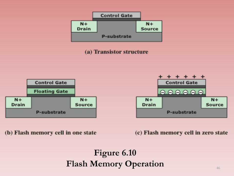
Figure 6.10
Flash Memory Operation 46

SSD Compared to HDD
SSDs have the following advantages over HDDs:
• High-performance input/output operations per second (IOPS)
• Durability
• Longer lifespan
• Lower power consumption
• Quieter and cooler running capabilities
• Lower access times and latency rates
Table
6.5
47

SSD
Organization
48

Practical Issues
• SDD performance has a tendency to slow down as the device is used – The entire block must be read
from the flash memory and placed in a RAM buffer
– Before the block can be written back to flash memory, the entire block of flash memory must be erased
– The entire block from the buffer is now written back to the flash memory
• Flash memory becomes
unusable after a certain number
of writes
– Techniques for prolonging life:
• Front-ending the flash with a
cache to delay and group write
operations
• Using wear-leveling algorithms
that evenly distribute writes across
block of cells
• Bad-block management techniques
– Most flash devices estimate their
own remaining lifetimes so systems
can anticipate failure and take
preemptive action
There are two practical issues peculiar to SSDs that are not faced by
HDDs:
49

Table 6. 6
Optical
Disk
Products
50

Compact Disk Read-Only Memory
(CD-ROM) • Audio CD and the CD-ROM share a similar technology
– The main difference is that CD-ROM players are more rugged and
have error correction devices to ensure that data are properly transferred
• Production:
– The disk is formed from a resin such as polycarbonate
– Digitally recorded information is imprinted as a series of microscopic pits on
the surface of the polycarbonate
- This is done with a finely focused, high intensity laser to create a master
disk
– The master is used, in turn, to make a die to stamp out copies onto
polycarbonate
– The pitted surface is then coated with a highly reflective surface, usually
aluminum or gold
– This shiny surface is protected against dust and scratches by a top
coat of clear acrylic
– Finally a label can be silkscreened onto the acrylic 51
CDs and CD-ROM • Information organized by using single spiral track – beginning near
the center and spiraling out to the outer edge of the disk.
• Sectors near the outside of the disk are the same length as those
near the inside.
• Thus, information is packed evenly across the disk in segments of
the same size and these are scanned at the same rate by rotating the
disk at a variable speed.
• The pits are then read by the laser at a constant linear velocity
(CLV).
• The disk rotates more slowly for access near the outer edge than for
those near the center.
• Thus, the capacity of a track and the rotational delay both increase
for positions nearer the outer edge of the disk.
• The data capacity for a CD-ROM is about 680 MB. 52

CD Operation
53

CD-ROM • CD-ROM is appropriate for the distribution of large amounts of
data to a large number of users
• Because the expense of the initial writing process it is not appropriate for individualized applications
• The CD-ROM has two advantages:
1. The optical disk together with the information stored on it can be mass replicated inexpensively
2. The optical disk is removable, allowing the disk itself to be used for archival storage
• The CD-ROM disadvantages:
1. It is read-only and cannot be updated
2. It has an access time much longer than that of a magnetic disk drive
Semester II 2014/2015 54
CD Recordable (CD-R) • Write-once read-many (WORM)
• Accommodates applications in which only one or a small
number of copies of a set of data is needed
• Disk is prepared in such a way that it can be subsequently written
once with a laser beam of modest-intensity
• Medium includes a dye layer which is used to change reflectivity
and is activated by a high-intensity laser
• Provides a permanent record of large volumes of user data
Semester II 2014/2015 55

CD Rewritable (CD-RW) • Can be repeatedly written and overwritten
• Phase change disk uses a material that has two significantly
different reflectivities in two different phase states
• Amorphous state
– Molecules exhibit a random orientation that reflects light poorly
• Crystalline state
– Has a smooth surface that reflects light well
• A beam of laser light can change the material from one phase to
the other
• Disadvantage is that the material eventually and permanently
loses its desirable properties
• Advantage is that it can be rewritten
56

Digital Versatile Disk (DVD)
• The DVD takes video into digital age.
• It delivers movies with impressive picture quality, and it can be
randomly accessed like audio CDs, which DVD machine can also
play.
• Vast volumes of data can be crammed onto the disk, currently
seven times as much as a CD-ROM.
• The DVD’s greater capacity is due to the three differences from
CDs:
1. Bits are packed more closely.
2. The DVD employs a second layer of pits and lands on top of the first
layer.
3. The DVD-ROM can be two-sided.
Semester II 2014/2015 57

Digital
Versatile Disk
(DVD)
58

High-Definition Optical Disks
• Designed to store high-definition videos and to provide
significantly greater storage capacity compared to DVDs.
• The higher bit density is achieved by using a laser with a shorter
wavelength, in the blue-violet range.
• The data pits, which constitute the digital 1s and 0s, are smaller
on the high-definition optical disks compared to DVD because
of the shorter laser wavelength.
Semester II 2014/2015 59

High-Definition Optical Disks
• Two competing disk formats and technologies initially competed
for market acceptance: HD DVD and Blu-ray DVD.
• The Blu-ray scheme ultimately achieved market dominance. The
HD DVD scheme can store 15 GB on a single layer on a single
side. Blu-ray positions the data layer on the disk closer to the
laser (shown on the right-hand side of each diagram in Figure
6.15).
• This enables a tighter focus and less distortion and thus smaller
pits and tracks. Blu-ray can store 25 GB on a single layer.
• Three versions are available: read only (BD-ROM), recordable
once (BD-R), and re-recordable (BD-RE).
Semester II 2014/2015 60

High-Definition
Optical Disks
61

Magnetic Tape
• Tape systems use the same reading and recording techniques as
disk systems
• Medium is flexible polyester tape coated with magnetizable
material
• Coating may consist of particles of pure metal in special binders
or vapor-plated metal films
• Data on the tape are structured as a number of parallel tracks
running lengthwise
• Serial recording
– Data are laid out as a sequence of bits along each track
– Data are read and written in contiguous blocks called physical records
– Blocks on the tape are separated by gaps referred to as inter-record gaps
Semester II 2014/2015 62

Magnetic Tape
Features
63

Table 6.7
LTO Tape Drives
64


![Lecture07 Recovery[1]](https://static.documents.pub/doc/80x56/577cd8d11a28ab9e78a21110/lecture07-recovery1.jpg)
