36
Kingfisher PLUS+ G30 Hardware Manual

Kingfisher PLUS+
G30 Hardware Manual
G30 Hardware Manual 1.3 www.rtunet.com/support Page 2
Document Information
Document Control
Copyright Copyright CSE-Semaphore (Australia) Pty Ltd. ABN 35 006 805 910 [email protected], www.rtunet.com
Intellectual Property CSE-Semaphore asserts ownership of the intellectual property contained herein and claims copyright and authorship. CSE-Semaphore has and retains all rights of ownership and use of the material herein in its on-going business.
Licence
This document is provided to the intended recipient(s) under a non-exclusive licence. This licence permits Fair Use of the document for operational requirements, without payment of further royalty or licence fee. Fair Use includes making copies of the document for operational, backup and archive purposes. Fair Use includes distributing copies of the document to other entities for the purposes of their performing related works for the intended recipient(s). Fair Use does not include creating, selling or distributing copies of the document for other purposes. All copies must retain this statement of Intellectual Property and Copyright.
Revision History Rev. Date Summary 1.0 4/10/2007 First release. G30 (stand-alone) processor and supported hardware. Serial comms option card
will be supported in a future firmware release. Other comms option cards will soon be available. 1.1 20/3/2008 Updated G30 isolation specifications. G30 (firmware 1704+) now supports OPT-SER serial option
boards. Added more interface cables. 1.2 4/9/2008 Added Series 3 (G3, G30) to Series 2 (CP-xx, PC-1, LP-x) serial port conversion cable (allows
Series 2 standard cables to be directly connected). Added additional safety warnings. Updated Glossary. Updated GSM Modem cable. Added DIN rail mounting bracket. Updated RS422/RS485 wiring diagrams. Added wiring examples for PSO-ACR power supply card.
1.3 11/12/2008 Updated the digital input voltage range specification for the IOD-MXx modules. Added installation warning regarding Restricted Access Locations. Changed name of chapter “Mounting” to “Installation”
G30 Hardware Manual 1.3 www.rtunet.com/support Page 3
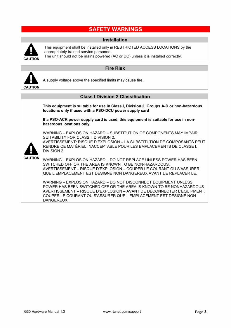
SAFETY WARNINGS
Installation
CAUTION
This equipment shall be installed only in RESTRICTED ACCESS LOCATIONS by the appropriately trained service personnel. The unit should not be mains powered (AC or DC) unless it is installed correctly.
Fire Risk
CAUTION
A supply voltage above the specified limits may cause fire.
Class I Division 2 Classification
CAUTION
This equipment is suitable for use in Class I, Division 2, Groups A-D or non-hazardous locations only if used with a PSO-DCU power supply card If a PSO-ACR power supply card is used, this equipment is suitable for use in non-hazardous locations only. WARNING – EXPLOSION HAZARD – SUBSTITUTION OF COMPONENTS MAY IMPAIR SUITABILITY FOR CLASS I, DIVISION 2. AVERTISSEMENT: RISQUE D’EXPLOSION – LA SUBSTITUTION DE COMPOSANTS PEUT RENDRE CE MATÉRIEL INACCEPTABLE POUR LES EMPLACEMENTS DE CLASSE I, DIVISION 2. WARNING – EXPLOSION HAZARD – DO NOT REPLACE UNLESS POWER HAS BEEN SWITCHED OFF OR THE AREA IS KNOWN TO BE NON-HAZARDOUS. AVERTISSEMENT – RISQUE D’EXPLOSION – COUPER LE COURANT OU S’ASSURER QUE L’EMPLACEMENT EST DÉSIGNÉ NON DANGEREUX AVANT DE REPLACER LE. WARNING – EXPLOSION HAZARD – DO NOT DISCONNECT EQUIPMENT UNLESS POWER HAS BEEN SWITCHED OFF OR THE AREA IS KNOWN TO BE NONHAZARDOUS AVERTISSEMENT – RISQUE D’EXPLOSION – AVANT DE DÉCONNECTER L’EQUIPMENT, COUPER LE COURANT OU S’ASSURER QUE L’EMPLACEMENT EST DÉSIGNÉ NON DANGEREUX.
G30 Hardware Manual 1.3 www.rtunet.com/support Page 4
Contents
1. G30 Standalone RTU................................ ................................ ............ 5
G30 OLED Displays ....................................................................................................................................... 5 G30 Processor Specifications ........................................................................................................................ 6
2. Comms Cards................................ ................................ ....................... 8
Isolated Serial Card (OPT-SER) .................................................................................................................... 8
3. Power Supply Cards ................................ ................................ .......... 10
AC Input Card, Regulated (PSO-ACR) - Non Hazardous Locations Only ................................................... 10 DC Input Card, Unregulated (PSO-DCU)..................................................................................................... 13
4. IO Daughter Cards ................................ ................................ ............. 15
IO Daughter Card - MX2: 14DI, 8DO, 6AI (IOD-MX2) ................................................................................. 15 IO Daughter Card - MX3: 14DI, 8DO, 6AI, 2AO (IOD-MX3) ........................................................................ 15 IO Daughter Card - MX4: 16DI, 16DO (IOD-MX4)....................................................................................... 21
5. Interface Cables ................................ ................................ ................. 26
G30 Ethernet Connection Cable .................................................................................................................. 26 G30 Serial Port Converter ............................................................................................................................ 27 G30 to G30 Serial Crossover Cable............................................................................................................. 27 G30 to CP-xx Serial Crossover Cable.......................................................................................................... 27 PSTN Modems and GSMs ........................................................................................................................... 28 Trio M Series Radio...................................................................................................................................... 28 MaxStream External Spread Spectrum Radio ............................................................................................. 29
6. Installation................................ ................................ .......................... 30
Panel Installation .......................................................................................................................................... 30 DIN Rail Installation...................................................................................................................................... 30
7. Glossary................................ ................................ .............................. 31
8. Appendix: Assembly Instructions ................................ .................... 32

G30 Hardware Manual 1.3 www.rtunet.com/support Page 5
1. G30 Standalone RTU
FEATURES
C-tick and electrical safety compliant for Australia/NZ
Supports logic written in any of the international IEC61131-3 control languages
OLED Display and four status lights
Three button controls
Up to three communications ports
One power supply card
Optional IO card
Optional comms card The G30 is a standalone (self contained) RTU that allows a power supply card (required), an IO card (optional) and a comms card (optional) to be installed within its enclosure. This allows the G30 to be setup for a wide variety of applications that require a compact RTU.
G30 OLED Displays
GENERAL:
RTU address 1 System ID AE
Firmware 1595
YY/MM/DD HH:MM:SS
ETHERNET:
IP 192.168.0.1 Sub 255.255.255.0
Gwy 0.0.0.0
Interface UDP
Tx Pkts 12345 Rx Pkts 12345
STATISTICS:
RX Failures 5 RX Successes 100
TX Failures 8
TX Successes 118
HARDWARE:
PSO-xxx OK IOD-xxx OK
Ethernet OK
POWER SUPPLY:
Type PSO-xxx
V-out 13.8V
I-out mA 200mA I-bat mA 150mA
Temperature 21°C
DI1 OFF DI9 ON
DI2 OFF DI10 ON DI3 ON DI11 OFF
DI4 OFF DI12 OFF
DI5 ON DI13 OFF DI6 OFF DI14 ON
DI7 ON DI15 ON
DI8 ON DI16 OFF
DO1 ON DO9 ON
DO2 OFF DO10 ON DO3 ON DO11 OFF
DO4 OFF DO12 OFF
DO5 ON DO13 OFF DO6 OFF DO14 ON
DO7 ON DO15 ON
DO8 ON DO16 OFF
G30 Hardware Manual 1.3 www.rtunet.com/support Page 6
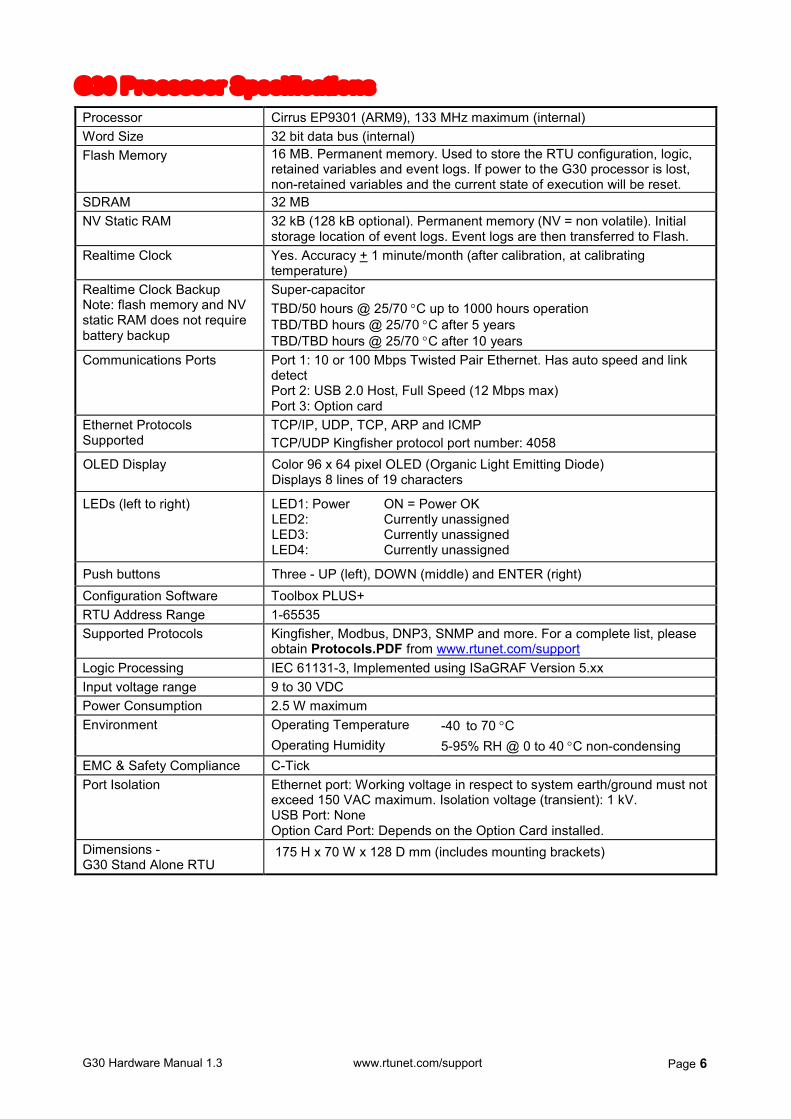
G30 Processor Specifications Processor Cirrus EP9301 (ARM9), 133 MHz maximum (internal) Word Size 32 bit data bus (internal) Flash Memory 16 MB. Permanent memory. Used to store the RTU configuration, logic,
retained variables and event logs. If power to the G30 processor is lost, non-retained variables and the current state of execution will be reset.
SDRAM 32 MB NV Static RAM 32 kB (128 kB optional). Permanent memory (NV = non volatile). Initial
storage location of event logs. Event logs are then transferred to Flash. Realtime Clock Yes. Accuracy + 1 minute/month (after calibration, at calibrating
temperature) Realtime Clock Backup Note: flash memory and NV static RAM does not require battery backup
Super-capacitor TBD/50 hours @ 25/70 C up to 1000 hours operation TBD/TBD hours @ 25/70 C after 5 years TBD/TBD hours @ 25/70 C after 10 years
Communications Ports Port 1: 10 or 100 Mbps Twisted Pair Ethernet. Has auto speed and link detect Port 2: USB 2.0 Host, Full Speed (12 Mbps max) Port 3: Option card
Ethernet Protocols Supported
TCP/IP, UDP, TCP, ARP and ICMP TCP/UDP Kingfisher protocol port number: 4058
OLED Display Color 96 x 64 pixel OLED (Organic Light Emitting Diode) Displays 8 lines of 19 characters
LEDs (left to right) LED1: Power ON = Power OK LED2: Currently unassigned LED3: Currently unassigned LED4: Currently unassigned
Push buttons Three - UP (left), DOWN (middle) and ENTER (right) Configuration Software Toolbox PLUS+ RTU Address Range 1-65535 Supported Protocols Kingfisher, Modbus, DNP3, SNMP and more. For a complete list, please
obtain Protocols.PDF from www.rtunet.com/support Logic Processing IEC 61131-3, Implemented using ISaGRAF Version 5.xx Input voltage range 9 to 30 VDC Power Consumption 2.5 W maximum
Operating Temperature -40 to 70 C Environment Operating Humidity 5-95% RH @ 0 to 40 C non-condensing
EMC & Safety Compliance C-Tick Port Isolation Ethernet port: Working voltage in respect to system earth/ground must not
exceed 150 VAC maximum. Isolation voltage (transient): 1 kV. USB Port: None Option Card Port: Depends on the Option Card installed.
Dimensions - G30 Stand Alone RTU
175 H x 70 W x 128 D mm (includes mounting brackets)
G30 Hardware Manual 1.3 www.rtunet.com/support Page 7
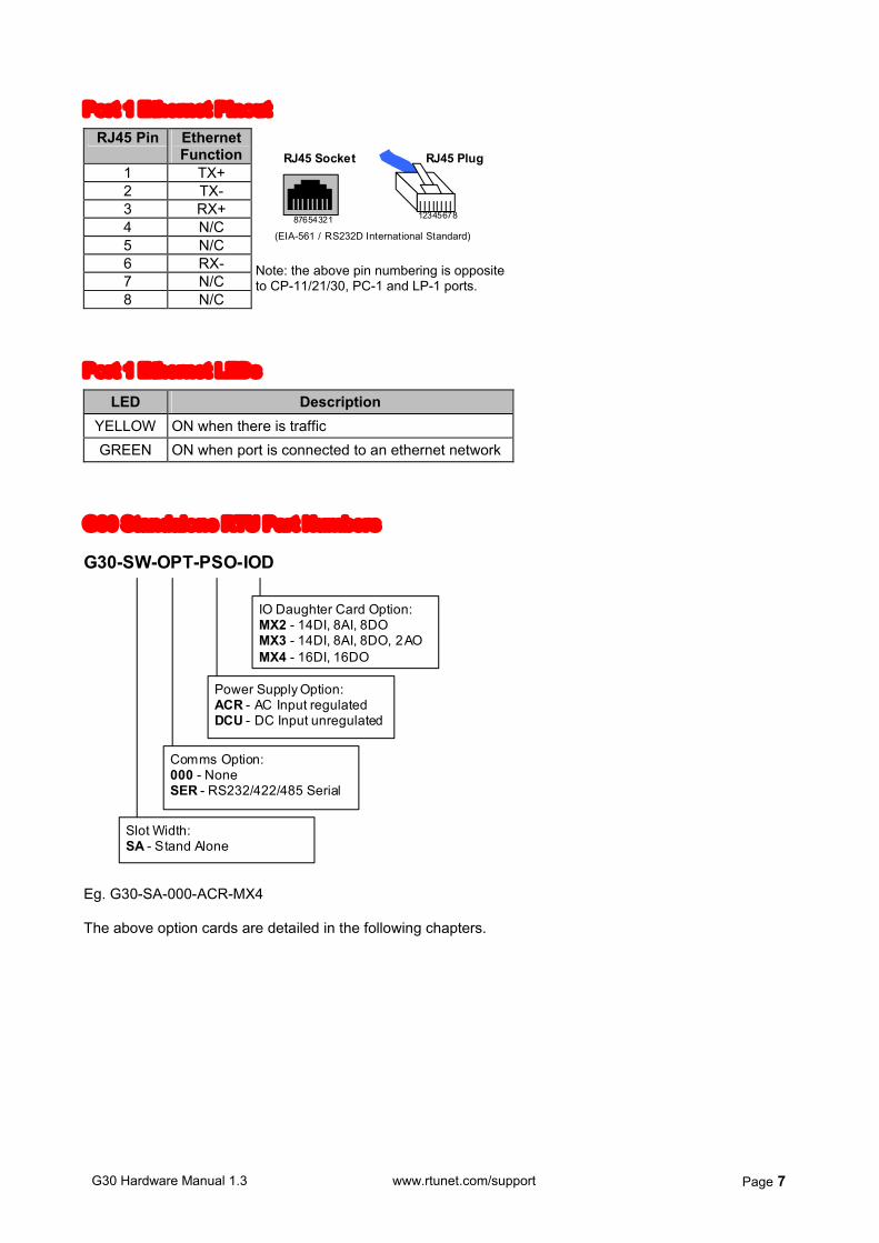
Port 1 Ethernet Pinout
RJ45 Pin Ethernet Function
1 TX+ 2 TX- 3 RX+ 4 N/C 5 N/C 6 RX- 7 N/C 8 N/C
RJ45 Socket RJ45 Plug
87654321 12345678
(EIA-561 / RS232D International Standard) Note: the above pin numbering is opposite to CP-11/21/30, PC-1 and LP-1 ports.
Port 1 Ethernet LEDs
LED Description YELLOW ON when there is traffic GREEN ON when port is connected to an ethernet network
G30 Standalone RTU Part Numbers
G30-SW-OPT-PSO-IOD
Power Supply Option: ACR - AC Input regulated DCU - DC Input unregulated
IO Daughter Card Option: MX2 - 14DI, 8AI, 8DO MX3 - 14DI, 8AI, 8DO, 2AO MX4 - 16DI, 16DO
Comms Option: 000 - None SER - RS232/422/485 Serial
Slot Width: SA - Stand Alone
Eg. G30-SA-000-ACR-MX4 The above option cards are detailed in the following chapters.
G30 Hardware Manual 1.3 www.rtunet.com/support Page 8
2. Comms Cards
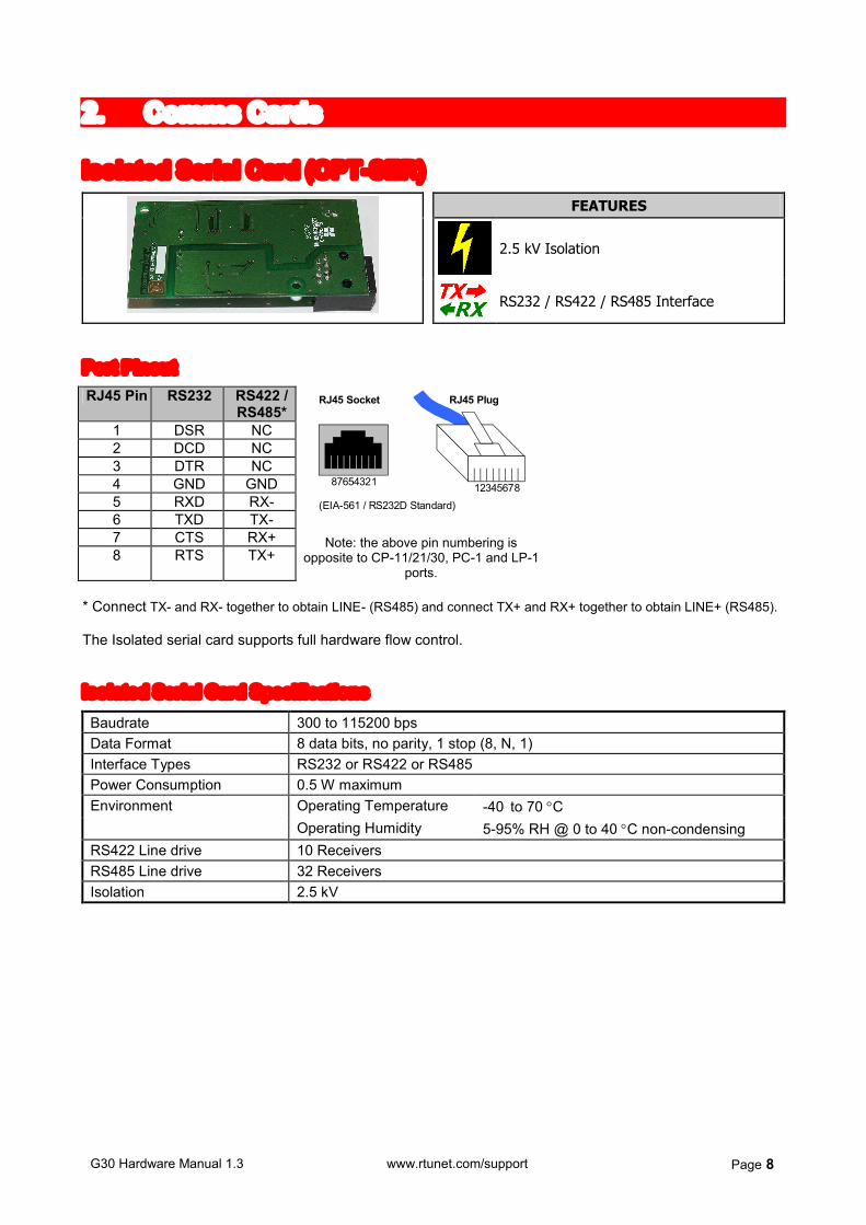
Isolated Serial Card (OPT-SER) FEATURES
2.5 kV Isolation
RS232 / RS422 / RS485 Interface
Port Pinout RJ45 Pin RS232 RS422 /
RS485* 1 DSR NC 2 DCD NC 3 DTR NC 4 GND GND 5 RXD RX- 6 TXD TX- 7 CTS RX+ 8 RTS TX+
RJ45 Socket RJ45 Plug
87654321 12345678 (EIA-561 / RS232D Standard)
Note: the above pin numbering is opposite to CP-11/21/30, PC-1 and LP-1
ports. * Connect TX- and RX- together to obtain LINE- (RS485) and connect TX+ and RX+ together to obtain LINE+ (RS485). The Isolated serial card supports full hardware flow control. Isolated Serial Card Specifications Baudrate 300 to 115200 bps Data Format 8 data bits, no parity, 1 stop (8, N, 1) Interface Types RS232 or RS422 or RS485 Power Consumption 0.5 W maximum
Operating Temperature -40 to 70 C Environment Operating Humidity 5-95% RH @ 0 to 40 C non-condensing
RS422 Line drive 10 Receivers RS485 Line drive 32 Receivers Isolation 2.5 kV
G30 Hardware Manual 1.3 www.rtunet.com/support Page 9
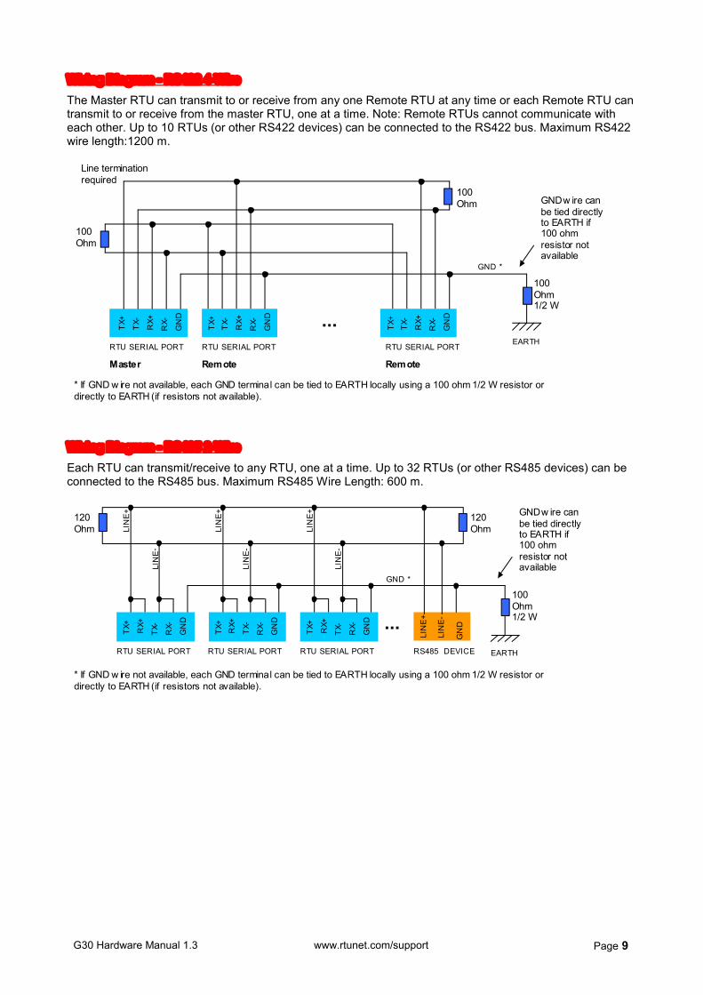
Wiring Diagram - RS422 4-Wire
The Master RTU can transmit to or receive from any one Remote RTU at any time or each Remote RTU can transmit to or receive from the master RTU, one at a time. Note: Remote RTUs cannot communicate with each other. Up to 10 RTUs (or other RS422 devices) can be connected to the RS422 bus. Maximum RS422 wire length:1200 m.
100 Ohm
100 Ohm
... TX+
RX+
T
X-
RX-
RTU SERIAL PORT
Master
Line termination required
EARTH
100 Ohm 1/2 W
GND w ire can be tied directly to EARTH if 100 ohm resistor not available GND *
* If GND w ire not available, each GND terminal can be tied to EARTH locally using a 100 ohm 1/2 W resistor or directly to EARTH (if resistors not available).
GN
D
TX+
RX+
T
X-
RX-
Remote
GN
D
TX+
RX+
T
X-
RX-
Remote
GN
D
RTU SERIAL PORT RTU SERIAL PORT
Wiring Diagram - RS485 2-Wire
Each RTU can transmit/receive to any RTU, one at a time. Up to 32 RTUs (or other RS485 devices) can be connected to the RS485 bus. Maximum RS485 Wire Length: 600 m.
120 Ohm
RTU SERIAL PORT
LIN
E+
LIN
E-
GN
D ...
120 Ohm
RS485 DEVICE
TX+
R
X+
TX-
R
X-
GN
D
LIN
E+
LIN
E-
TX+
R
X+
TX-
R
X-
GN
D
LIN
E+
LIN
E-
TX+
R
X+
TX-
R
X-
GN
D
LIN
E+
LIN
E-
EARTH
100 Ohm 1/2 W
GND w ire can be tied directly to EARTH if 100 ohm resistor not available
GND *
* If GND w ire not available, each GND terminal can be tied to EARTH locally using a 100 ohm 1/2 W resistor or directly to EARTH (if resistors not available).
RTU SERIAL PORT RTU SERIAL PORT

G30 Hardware Manual 1.3 www.rtunet.com/support Page 10
3. Power Supply Cards
AC Input Card, Regulated (PSO-ACR) - Non Hazardous Locations Only
FEATURES
AC or DC Input Supply
Auxiliary DC Output
Monitoring - supply voltage and current
Low Voltage Shutdown
Backup Battery Charging
This power supply card accepts AC / DC mains input (or DC battery input) and outputs DC voltages used to power the G30 and external equipment such as a radio. It also provides monitoring and protection of the power supply circuitry. WARNING: If a PSO-ACR power supply card is used, the G30 RTU is suitable for use in non-hazardous locations only.
G30 Hardware Manual 1.3 www.rtunet.com/support Page 11
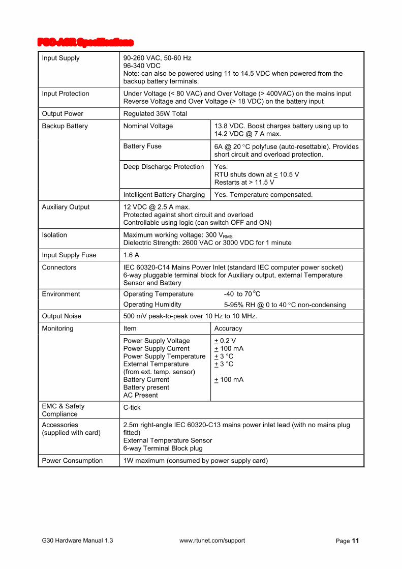
PSO-ACR Specifications
Input Supply 90-260 VAC, 50-60 Hz 96-340 VDC Note: can also be powered using 11 to 14.5 VDC when powered from the backup battery terminals.
Input Protection Under Voltage (< 80 VAC) and Over Voltage (> 400VAC) on the mains input Reverse Voltage and Over Voltage (> 18 VDC) on the battery input
Output Power Regulated 35W Total
Nominal Voltage 13.8 VDC. Boost charges battery using up to 14.2 VDC @ 7 A max.
Battery Fuse 6A @ 20 C polyfuse (auto-resettable). Provides short circuit and overload protection.
Deep Discharge Protection Yes. RTU shuts down at < 10.5 V Restarts at > 11.5 V
Backup Battery
Intelligent Battery Charging Yes. Temperature compensated.
Auxiliary Output 12 VDC @ 2.5 A max. Protected against short circuit and overload Controllable using logic (can switch OFF and ON)
Isolation Maximum working voltage: 300 VRMS Dielectric Strength: 2600 VAC or 3000 VDC for 1 minute
Input Supply Fuse 1.6 A
Connectors IEC 60320-C14 Mains Power Inlet (standard IEC computer power socket) 6-way pluggable terminal block for Auxiliary output, external Temperature Sensor and Battery Operating Temperature -40 to 70 oC Environment Operating Humidity 5-95% RH @ 0 to 40 C non-condensing
Output Noise 500 mV peak-to-peak over 10 Hz to 10 MHz.
Item Accuracy Monitoring
Power Supply Voltage Power Supply Current Power Supply Temperature External Temperature (from ext. temp. sensor) Battery Current Battery present AC Present
+ 0.2 V + 100 mA + 3 °C + 3 °C + 100 mA
EMC & Safety Compliance
C-tick
Accessories (supplied with card)
2.5m right-angle IEC 60320-C13 mains power inlet lead (with no mains plug fitted) External Temperature Sensor 6-way Terminal Block plug
Power Consumption 1W maximum (consumed by power supply card)
G30 Hardware Manual 1.3 www.rtunet.com/support Page 12
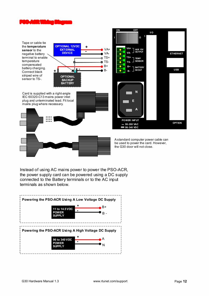
PSO-ACR Wiring Diagram
OPTION
I/ OON
VA+
VA-
TS+
TS-
B+
B- USB
ETHERNET
1
AUX 12VOUTPUT
TEMPSENSOR
BATTERYIN/OUT
I O
OFF
POWER INPUT90-260 VAC
96-340 VDC~
Tape or cable tie the temperature sensor to the negative battery terminal to enable temperature compensated battery charging. Connect black striped wire of sensor to TS-.
+ -
TS+ TS- B+ B-
+ - VA+
VA-
OPTIONAL 12VDC EXTERNAL
DEVICE
A standard computer power cable can be used to power the card. However, the G30 door will not close.
Card is supplied with a right-angle IEC 60320-C13 mains power inlet plug and unterminated lead. Fit local mains plug where necessary.
E
N
A
OPTIONAL BACKUP BATTERY
+ -
B+
B -
+ - 11 to 14.5 VDC
POWER SUPPLY
Powering the PSO-ACR Using A Low Voltage DC Supply
A
N
+ - 96 to 340 VDC
POWER SUPPLY
Powering the PSO-ACR Using A High Voltage DC Supply
Instead of using AC mains power to power the PSO-ACR, the power supply card can be powered using a DC supply connected to the Battery terminals or to the AC input terminals as shown below.

G30 Hardware Manual 1.3 www.rtunet.com/support Page 13
DC Input Card, Unregulated (PSO-DCU) FEATURES
Monitoring - supply voltage and current
Power using an external DC supply
Auxiliary DC Output
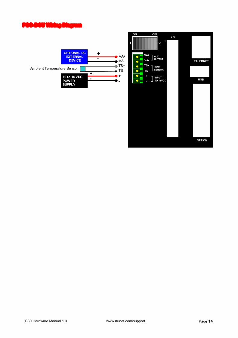
This card is powered from a DC input supply. It provides over and reverse voltage protection but otherwise does not regulate the supply voltage. The card provides power for the G30, provides an auxiliary output for external equipment and monitors the input supply voltage and current. PSO-DCU Specifications
Input Supply 10-16 VDC, 2.5 A maximum
Input Protection Over voltage and reverse voltage
Outputs Auxiliary 2.0 A max @ Input Supply voltage. Auxiliary output has over current and short circuit protection and can be controlled (switched OFF and ON) using logic.
Input Supply - Low Voltage shutdown
<10 V
Isolation None
Supply Fuse Internal 6 A polyfuse (auto-resettable)
Connector 6-way pluggable terminal block for Auxiliary output, external Temperature Sensor and Input Supply Operating Temperature -40 to 70 oC Environment Operating Humidity 5-95% RH @ 0 to 40 C non-condensing
Item Accuracy Monitoring
Supply Voltage Supply Current Card Temperature External Temperature (from ext. temp. sensor)
+ 0. 2 V + 100 mA + 3 °C + 3 °C
EMC & Safety Compliance
C-tick
Accessories (supplied with card)
External Temperature Sensor 6-way Terminal Block plug
Power Consumption 1 W maximum (consumed by power supply card)
G30 Hardware Manual 1.3 www.rtunet.com/support Page 14
PSO-DCU Wiring Diagram
OPTION
I/ OON
VA+
VA-
TS+
TS-
+
- USB
ETHERNET
1
AUXOUTPUT
TEMPSENSOR
INPUT10~30VDC
I O
OFF
TS+ TS- + -
+ - VA+
VA-
OPTIONAL DC EXTERNAL
DEVICE
Ambient Temperature Sensor + - 10 to 16 VDC
POWER SUPPLY
INPUT 10~16VDC

G30 Hardware Manual 1.3 www.rtunet.com/support Page 15
4. IO Daughter Cards
IO Daughter Card - MX2: 14DI, 8DO, 6AI (IOD-MX2) IO Daughter Card - MX3: 14DI, 8DO, 6AI, 2AO (IOD-MX3)
FEATURES
6 Analog Inputs (software configurable as current or voltage inputs)
2 Analog Outputs (MX3 only)
16-Bit Analog Resolution
Isolated DC Output for Loop Power
8 Transistor Outputs
14 Digital Inputs
500V RMS Channel to Logic Isolation
The MX3 is identical to the MX2 except it has two additional Analog outputs. Digital Inputs: Can be powered from the card's own auxiliary output or an external supply can be used. Current through an input (in either direction) results in a logic 1 in the status register. Digital Outputs: Can be configured for high speed pulse outputs if desired. Analog Inputs: Can be configured as current or voltage inputs using software. Analog Outputs (IOD-MX-3 only): Provide current and voltage outputs. Outputs can be powered by the card itself or from an external supply.
G30 Hardware Manual 1.3 www.rtunet.com/support Page 16
Specifications
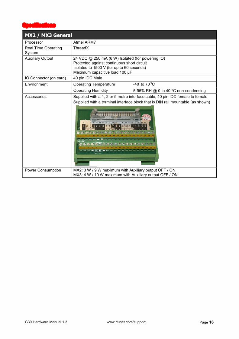
MX2 / MX3 General Processor Atmel ARM7 Real Time Operating System
ThreadX
Auxiliary Output 24 VDC @ 250 mA (6 W) Isolated (for powering IO) Protected against continuous short circuit Isolated to 1500 V (for up to 60 seconds) Maximum capacitive load 100 µF
IO Connector (on card) 40 pin IDC Male Operating Temperature -40 to 70 oC Environment Operating Humidity 5-95% RH @ 0 to 40 C non-condensing
Accessories Supplied with a 1, 2 or 5 metre interface cable, 40 pin IDC female to female Supplied with a terminal interface block that is DIN rail mountable (as shown)
Power Consumption MX2: 3 W / 9 W maximum with Auxiliary output OFF / ON
MX3: 4 W / 10 W maximum with Auxiliary output OFF / ON

G30 Hardware Manual 1.3 www.rtunet.com/support Page 17
MX2 / MX3 Digital Inputs Inputs per card 14 Rated Input Voltage 24 VDC (supports reverse polarity) Input Type Current Sinking Input Grouping 2 groups: inputs 1 to 6 and inputs 7 to 14. Each group has a separate common
Impedance 4.7 k On-state Voltage + 19.2 to 28.8 VDC Off-state Voltage + 0 to 5.0 VDC On-state Current 1.4 mA minimum. Current=(Vin-1.2) / 5.7 mA
Input Characteristics
Off-state Current 0.5 mA maximum Isolation 500 V RMS channel to logic
100 V RMS channel to channel between input groups 250 V RMS channel to field power 250 V RMS channel to other types of IO channels (DO, AI and AO) No isolation between channels in the same group
Input Scan Time 1 ms (for all channels) Debounce 0 (default) to 16000 ms configurable on any channel(s). Channel Inversion Yes. Selectable on any channel(s). Sequence Of Events Yes. Selectable on any channel(s). Triggered on change of state.
Can capture up to 1000 events per second Accurate to 1 ms.
Edge Counting Yes. Selectable on any channel(s). Can count rising or falling edges. Frequency Counting 10 kHz maximum on channels 1 and 2
500 Hz maximum on all other channels Quadrature Counting Selectable on input channels: 1&2, 3&4, 5&6, 7&8, 9&10, 11&12, 13&14
G30 Hardware Manual 1.3 www.rtunet.com/support Page 18
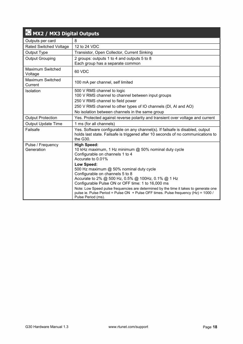
MX2 / MX3 Digital Outputs Outputs per card 8 Rated Switched Voltage 12 to 24 VDC Output Type Transistor, Open Collector, Current Sinking Output Grouping 2 groups: outputs 1 to 4 and outputs 5 to 8
Each group has a separate common Maximum Switched Voltage 60 VDC
Maximum Switched Current 100 mA per channel, self limited
Isolation 500 V RMS channel to logic 100 V RMS channel to channel between input groups 250 V RMS channel to field power 250 V RMS channel to other types of IO channels (DI, AI and AO) No isolation between channels in the same group
Output Protection Yes. Protected against reverse polarity and transient over voltage and current Output Update Time 1 ms (for all channels) Failsafe Yes. Software configurable on any channel(s). If failsafe is disabled, output
holds last state. Failsafe is triggered after 10 seconds of no communications to the G30.
Pulse / Frequency Generation
High Speed: 10 kHz maximum, 1 Hz minimum @ 50% nominal duty cycle Configurable on channels 1 to 4 Accurate to 0.01% Low Speed: 500 Hz maximum @ 50% nominal duty cycle Configurable on channels 5 to 8 Accurate to 2% @ 500 Hz, 0.5% @ 100Hz, 0.1% @ 1 Hz Configurable Pulse ON or OFF time: 1 to 16,000 ms Note: Low Speed pulse frequencies are determined by the time it takes to generate one pulse ie. Pulse Period = Pulse ON + Pulse OFF times. Pulse frequency (Hz) = 1000 / Pulse Period (ms).
G30 Hardware Manual 1.3 www.rtunet.com/support Page 19
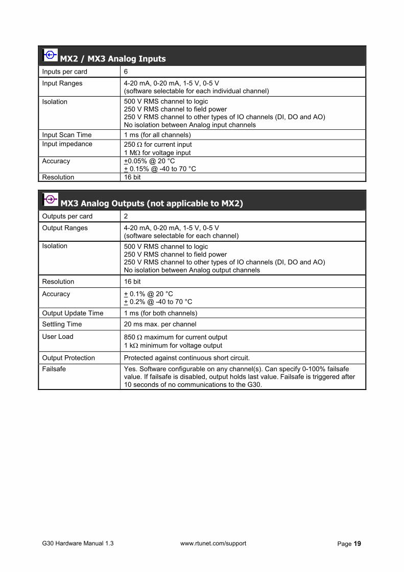
MX2 / MX3 Analog Inputs Inputs per card 6
Input Ranges 4-20 mA, 0-20 mA, 1-5 V, 0-5 V (software selectable for each individual channel)
Isolation 500 V RMS channel to logic 250 V RMS channel to field power 250 V RMS channel to other types of IO channels (DI, DO and AO) No isolation between Analog input channels
Input Scan Time 1 ms (for all channels) Input impedance 250 for current input
1 M for voltage input Accuracy +0.05% @ 20 °C
+ 0.15% @ -40 to 70 °C Resolution 16 bit
MX3 Analog Outputs (not applicable to MX2) Outputs per card 2
Output Ranges 4-20 mA, 0-20 mA, 1-5 V, 0-5 V (software selectable for each channel)
Isolation 500 V RMS channel to logic 250 V RMS channel to field power 250 V RMS channel to other types of IO channels (DI, DO and AO) No isolation between Analog output channels
Resolution 16 bit
Accuracy + 0.1% @ 20 °C + 0.2% @ -40 to 70 °C
Output Update Time 1 ms (for both channels) Settling Time 20 ms max. per channel
User Load 850 maximum for current output 1 k minimum for voltage output
Output Protection Protected against continuous short circuit. Failsafe Yes. Software configurable on any channel(s). Can specify 0-100% failsafe
value. If failsafe is disabled, output holds last value. Failsafe is triggered after 10 seconds of no communications to the G30.

G30 Hardware Manual 1.3 www.rtunet.com/support Page 20
MX2 / MX3 Wiring Diagram
IO POWERED BY CARD IO POWERED EXTERNALLY ANALOG INPUTS ANALOG INPUTS
AI x 24V
AI 1-6 COM
Analog 2-Wire Transmitter
+ -
+ -
Analog 3-Wire Transmitter
PWR
+ - Analog 4-Wire
Transmitter
AI x
24V
24V
AI 1-6 COM AI x
AI 1-6 COM 0V
PWR 0V
0V
+ -
AI x Analog 4-Wire Transmitter
PWR POWER SUPPLY
+ -
+ -
AI x
AI 1-6 COM
Analog 3-Wire Transmitter
PWR POWER SUPPLY
+ -
AI 1-6 COM
+ - AI x
AI 1-6 COM
Analog 2-Wire Transmitter
POWER SUPPLY
+
-
ANALOG OUTPUTS (IOD-MX3 only) * ANALOG OUTPUTS (IOD-MX3 only) *
24V AOxC
+ - Analog
Current Load AO 1-2 COM
0V
AOxV + - Analog
Voltage Load AO 1-2 COM
AOxC -
AO 1-2 COM POWER SUPPLY -
+ Analog Current Load
+
DIGITAL INPUTS DIGITAL INPUTS FIELD CONTACT
DI x 24V
DI y-z COM 0V
DI x
DI y-z COM
+ FIELD CONTACT
POWER SUPPLY
DIGITAL OUTPUTS DIGITAL OUTPUTS
DI14 DI13 40
DI12 DI11 38
DI10 DI9 36
33 DI8 DI7 34
DI 7-14 COM
DI 1-6 COM
32
DI6 DI5 30
DI4 DI3 28
DI2 DI1 26
DO8 DO7 24
DO6 DO5 22
DO 5-8 COM
DO 1-4 COM
20
DO4 DO3 18
DO2 DO1 16
AI6 AI5 14
AI4 AI3 12
AI2 AI1 10
AI 1- 6 COM
AO 1-2 COM*
8
AO2C* AO1C* 6
AO2V* AO1V* 4
24V 0V 2
39
37
35
31
29
27
25
23
21
19
17
15
13
11
9
7
5
3
1
Viewing Front Of Card TOP
NO
TCH
* IOD-MX3 Only
24V LOAD DO x
- +
DO y-z COM 0V
When output is energised, output channel is shorted to the DO COM terminal.
DO x
DO y-z COM
+ POWER SUPPLY
-
+ - LOAD
When output is energised, output channel is shorted to the DO COM terminal.
* Note: When using a mix of current and voltage Analog outputs, the accuracy of the voltage output will only be preserved if the voltage output has its own common wire (ie. not shared with the current output[s]).

G30 Hardware Manual 1.3 www.rtunet.com/support Page 21
IO Daughter Card - MX4: 16DI, 16DO (IOD-MX4)
FEATURES
16 Digital Inputs
16 Transistor Outputs
Isolated DC Output for Loop Power
500 V RMS Channel to Logic Isolation
Digital Inputs: Can be powered using the card's own auxiliary output or an external supply can be used. Current through an input (in either direction) results in a logic 1 in the status register. Digital Outputs: Can be configured for high speed pulse outputs if desired.
G30 Hardware Manual 1.3 www.rtunet.com/support Page 22
Specifications
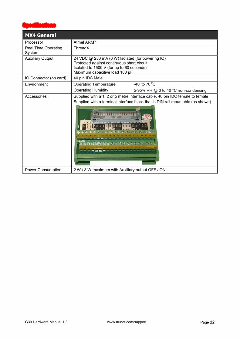
MX4 General Processor Atmel ARM7 Real Time Operating System
ThreadX
Auxiliary Output 24 VDC @ 250 mA (6 W) Isolated (for powering IO) Protected against continuous short circuit Isolated to 1500 V (for up to 60 seconds) Maximum capacitive load 100 µF
IO Connector (on card) 40 pin IDC Male Operating Temperature -40 to 70 oC Environment Operating Humidity 5-95% RH @ 0 to 40 C non-condensing
Accessories Supplied with a 1, 2 or 5 metre interface cable, 40 pin IDC female to female Supplied with a terminal interface block that is DIN rail mountable (as shown)
Power Consumption 2 W / 8 W maximum with Auxiliary output OFF / ON
G30 Hardware Manual 1.3 www.rtunet.com/support Page 23
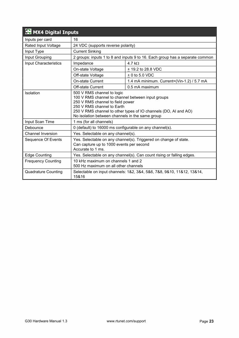
MX4 Digital Inputs Inputs per card 16 Rated Input Voltage 24 VDC (supports reverse polarity) Input Type Current Sinking Input Grouping 2 groups: inputs 1 to 8 and inputs 9 to 16. Each group has a separate common
Impedance 4.7 k On-state Voltage + 19.2 to 28.8 VDC Off-state Voltage + 0 to 5.0 VDC On-state Current 1.4 mA minimum. Current=(Vin-1.2) / 5.7 mA
Input Characteristics
Off-state Current 0.5 mA maximum Isolation 500 V RMS channel to logic
100 V RMS channel to channel between input groups 250 V RMS channel to field power 250 V RMS channel to Earth 250 V RMS channel to other types of IO channels (DO, AI and AO) No isolation between channels in the same group
Input Scan Time 1 ms (for all channels) Debounce 0 (default) to 16000 ms configurable on any channel(s). Channel Inversion Yes. Selectable on any channel(s). Sequence Of Events Yes. Selectable on any channel(s). Triggered on change of state.
Can capture up to 1000 events per second Accurate to 1 ms.
Edge Counting Yes. Selectable on any channel(s). Can count rising or falling edges. Frequency Counting 10 kHz maximum on channels 1 and 2
500 Hz maximum on all other channels Quadrature Counting Selectable on input channels: 1&2, 3&4, 5&6, 7&8, 9&10, 11&12, 13&14,
15&16
G30 Hardware Manual 1.3 www.rtunet.com/support Page 24
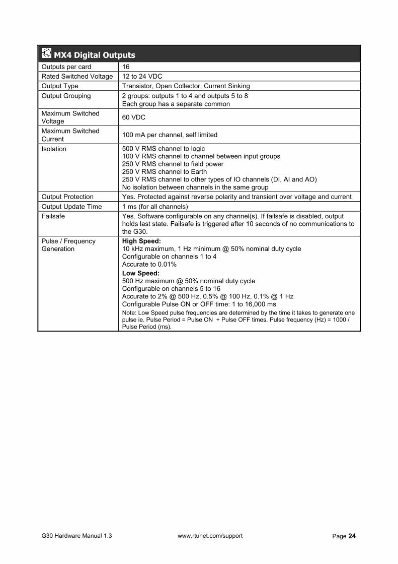
MX4 Digital Outputs Outputs per card 16 Rated Switched Voltage 12 to 24 VDC Output Type Transistor, Open Collector, Current Sinking Output Grouping 2 groups: outputs 1 to 4 and outputs 5 to 8
Each group has a separate common Maximum Switched Voltage 60 VDC
Maximum Switched Current 100 mA per channel, self limited
Isolation 500 V RMS channel to logic 100 V RMS channel to channel between input groups 250 V RMS channel to field power 250 V RMS channel to Earth 250 V RMS channel to other types of IO channels (DI, AI and AO) No isolation between channels in the same group
Output Protection Yes. Protected against reverse polarity and transient over voltage and current Output Update Time 1 ms (for all channels) Failsafe Yes. Software configurable on any channel(s). If failsafe is disabled, output
holds last state. Failsafe is triggered after 10 seconds of no communications to the G30.
Pulse / Frequency Generation
High Speed: 10 kHz maximum, 1 Hz minimum @ 50% nominal duty cycle Configurable on channels 1 to 4 Accurate to 0.01% Low Speed: 500 Hz maximum @ 50% nominal duty cycle Configurable on channels 5 to 16 Accurate to 2% @ 500 Hz, 0.5% @ 100 Hz, 0.1% @ 1 Hz Configurable Pulse ON or OFF time: 1 to 16,000 ms Note: Low Speed pulse frequencies are determined by the time it takes to generate one pulse ie. Pulse Period = Pulse ON + Pulse OFF times. Pulse frequency (Hz) = 1000 / Pulse Period (ms).
G30 Hardware Manual 1.3 www.rtunet.com/support Page 25
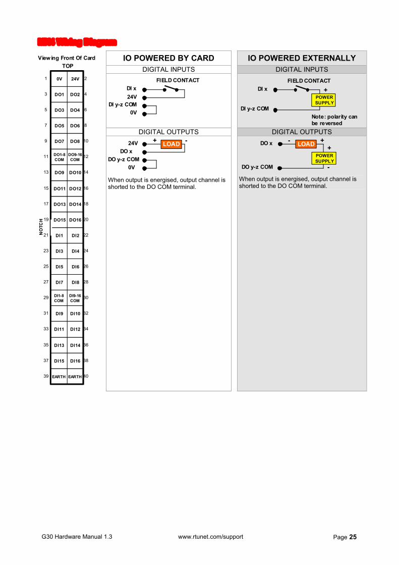
MX4 Wiring Diagram
IO POWERED BY CARD IO POWERED EXTERNALLY DIGITAL INPUTS DIGITAL INPUTS
FIELD CONTACT DI x 24V
DI y-z COM 0V
DI x
DI y-z COM
+ FIELD CONTACT
POWER SUPPLY
Note: polarity can be reversed
DIGITAL OUTPUTS DIGITAL OUTPUTS
EARTH EARTH 40
DI16 DI15 38
DI14 DI13 36
DI12 DI11 34
DI10 DI9 32
DI9-16 COM
DI1-8 COM
30
DI8 DI7 28
DI6 DI5 26
DI4 DI3 24
DI2 DI1 22
DO16 DO15 20
DO14 DO13 18
DO12 DO11 16
DO10 DO9 14
DO9-16 COM
DO1-8 COM
12
DO8 DO7 10
DO6 DO5 8
DO4 DO3 6
DO2 DO1 4
24V 0V 2
39
37
35
33
31
29
27
25
23
21
19
17
15
13
11
9
7
5
3
1
NO
TCH
Viewing Front Of Card TOP
24V LOAD DO x
- +
DO y-z COM 0V
When output is energised, output channel is shorted to the DO COM terminal.
DO x
DO y-z COM
+ POWER SUPPLY
-
+ - LOAD
When output is energised, output channel is shorted to the DO COM terminal.
G30 Hardware Manual 1.3 www.rtunet.com/support Page 26
5. Interface Cables
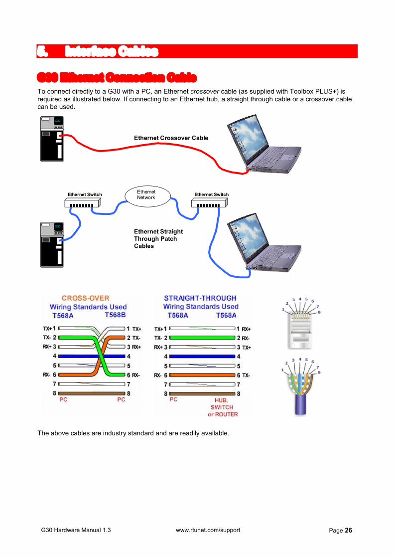
G30 Ethernet Connection Cable To connect directly to a G30 with a PC, an Ethernet crossover cable (as supplied with Toolbox PLUS+) is required as illustrated below. If connecting to an Ethernet hub, a straight through cable or a crossover cable can be used.
G30
G30
Ethernet Crossover Cable
Ethernet Switch
Ethernet Switch
Ethernet Network
Ethernet Straight Through Patch Cables
The above cables are industry standard and are readily available.
G30 Hardware Manual 1.3 www.rtunet.com/support Page 27
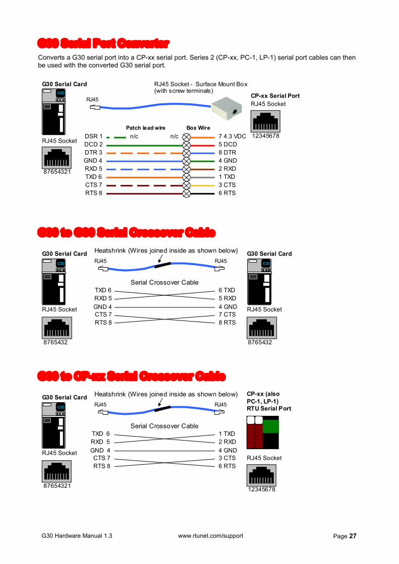
G30 Serial Port Converter Converts a G30 serial port into a CP-xx serial port. Series 2 (CP-xx, PC-1, LP-1) serial port cables can then be used with the converted G30 serial port.
RJ45 Socket - Surface Mount Box (with screw terminals)
RJ45
5 DCD
8 DTR
2 RXD 4 GND
DSR 1 DCD 2 DTR 3
RXD 5 TXD 6
GND 4
G30 Serial Card
3 CTS 1 TXD
RJ45 Socket
87654321
G30
CP-xx Serial Port
6 RTS CTS 7 RTS 8
7 4.3 VDC n/c Patch lead wire
RJ45 Socket
12345678
n/c Box Wire
G30 to G30 Serial Crossover Cable
RJ45
RXD 5 TXD 6
GND 4
6 TXD 5 RXD 4 GND 7 CTS 8 RTS
Heatshrink (Wires joined inside as shown below) RJ45
RTS 8 CTS 7
Serial Crossover Cable
G30 Serial Card
RJ45 Socket
87654321
G30 Serial Card
RJ45 Socket
87654321
G30
G30
G30 to CP-xx Serial Crossover Cable
TXD 6 RXD 5 GND 4 CTS 7 RTS 8
Heatshrink (Wires joined inside as shown below) RJ45 RJ45
Serial Crossover Cable
G30 Serial Card
RJ45 Socket
87654321
2 RXD 1 TXD
4 GND
6 RTS 3 CTS
CP-xx (also PC-1, LP-1) RTU Serial Port
RJ45 Socket
12345678
G30
G30 Hardware Manual 1.3 www.rtunet.com/support Page 28
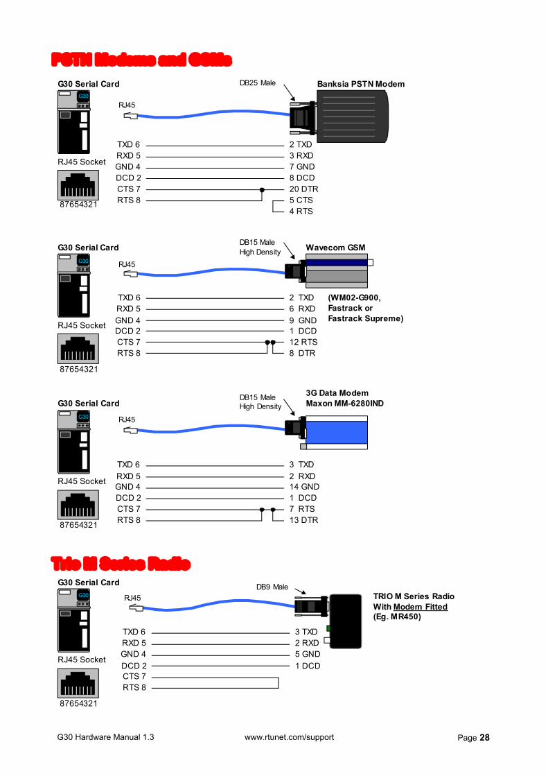
PSTN Modems and GSMs DB25 Male Banksia PSTN Modem
RJ45
3 RXD 2 TXD
7 GND
20 DTR 8 DCD
TXD 6 RXD 5 GND 4
CTS 7 RTS 8
DCD 2
G30 Serial Card
4 RTS 5 CTS
RJ45 Socket
87654321
G30
DB15 Male High Density Wavecom GSM
RJ45
6 RXD 2 TXD
9 GND 1 DCD
TXD 6 RXD 5 GND 4 DCD 2
G30 Serial Card
RJ45 Socket
87654321
G30
12 RTS CTS 7
RTS 8 8 DTR
(WM02-G900, Fastrack or Fastrack Supreme)
DB15 Male High Density
3G Data Modem Maxon MM-6280IND
RJ45
2 RXD 3 TXD
14 GND 1 DCD
TXD 6 RXD 5 GND 4 DCD 2
G30 Serial Card
RJ45 Socket
87654321
G30
7 RTS CTS 7 RTS 8 13 DTR
Trio M Series Radio DB9 Male
RJ45
2 RXD 3 TXD
5 GND 1 DCD
TXD 6 RXD 5 GND 4 DCD 2
TRIO M Series Radio With Modem Fitted (Eg. MR450)
G30 Serial Card
RJ45 Socket
87654321
G30
CTS 7 RTS 8
G30 Hardware Manual 1.3 www.rtunet.com/support Page 29
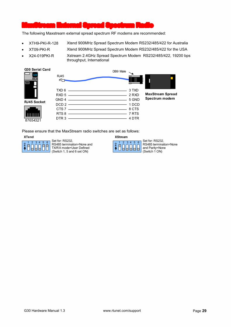
MaxStream External Spread Spectrum Radio The following Maxstream external spread spectrum RF modems are recommended: XTH9-PKI-R-128 Xtend 900MHz Spread Spectrum Modem RS232/485/422 for Australia
XT09-PKI-R Xtend 900MHz Spread Spectrum Modem RS232/485/422 for the USA
X24-019PKI-R Xstream 2.4GHz Spread Spectrum Modem RS232/485/422, 19200 bps throughput, International
DB9 Male
RJ45
2 RXD 3 TXD
5 GND 1 DCD
TXD 6 RXD 5 GND 4
CTS 7 RTS 8
DCD 2
MaxStream Spread Spectrum modem
8 CTS 7 RTS
DTR 3 4 DTR
G30 Serial Card
RJ45 Socket
87654321
G30
Please ensure that the MaxStream radio switches are set as follows:
1 2 3 4 5 6 O N
1 2 3 4 5 6 O N
Set for: RS232, RS485 termination=None and TX/RX mode=User Defined (Switch 1, 5 and 6 set ON)
Set for: RS232, RS485 termination=None and Parity=None (Switch 1 ON)
XTend XStream

G30 Hardware Manual 1.3 www.rtunet.com/support Page 30
6. Installation
Panel Installation
Use 4 screws to attach the G30 to a suitable flat surface. Ensure there is adequate ventilation below and above the unit and that any objects do not obstruct the ventilation holes.
CAUTION: This equipment shall be installed only in RESTRICTED ACCESS LOCATIONS by the appropriately trained service personnel.
CAUTION: The unit should not be mains powered (AC or DC)
unless it is installed correctly.
DIN Rail Installation
DIN rail bracket
G30 installed on DIN rail bracket
G30 Hardware Manual 1.3 www.rtunet.com/support Page 31
7. Glossary
AI, AO, DI, DO Analog Input, Analog Output, Digital Input and Digital Output respectively. Byte A group of 8 bits. Each bit can be a 0 (off) or a 1 (on) allowing up to 256 combinations. Card A PCB (printed circuit board) and its connectors. A card is housed within a module. Comms Communications Current Sinking Current is supplied into the RTU’s IO terminal. G30 A double width module that includes a Power Supply Card, a Processor Card and may
include an IO card and a comms option card. Runs the Linux operating system and supports ISAGRAF.
IO Input, Output IP Internet Protocol. Used for ethernet communications. Port A physical connection or socket on an RTU used for communications Processor Module Processor module containing a CPU (central processing unit) Protocol Refers to the format of messages that may be passed to, from and through an RTU in
communication with local and remote devices. Communications may use one or more RTU ports. Examples of protocols used within telemetry include Kingfisher, Modbus and DNP3.
RTU Acronym for Remote Terminal Unit. Describes a group of processor, communication and IO modules that comprise a device for monitoring and control of hardware and devices in remote locations.
TCP/IP Transfer Control Protocol / Internet Protocol. Commonly used for Ethernet communications.
UDP Universal Datagram Protocol.
G30 Hardware Manual 1.3 www.rtunet.com/support Page 32
8. Appendix: Assembly Instructions
This appendix describes how to assemble all the possible components in a G3-SA-xxx-xxx-xxx Stand Alone RTU.
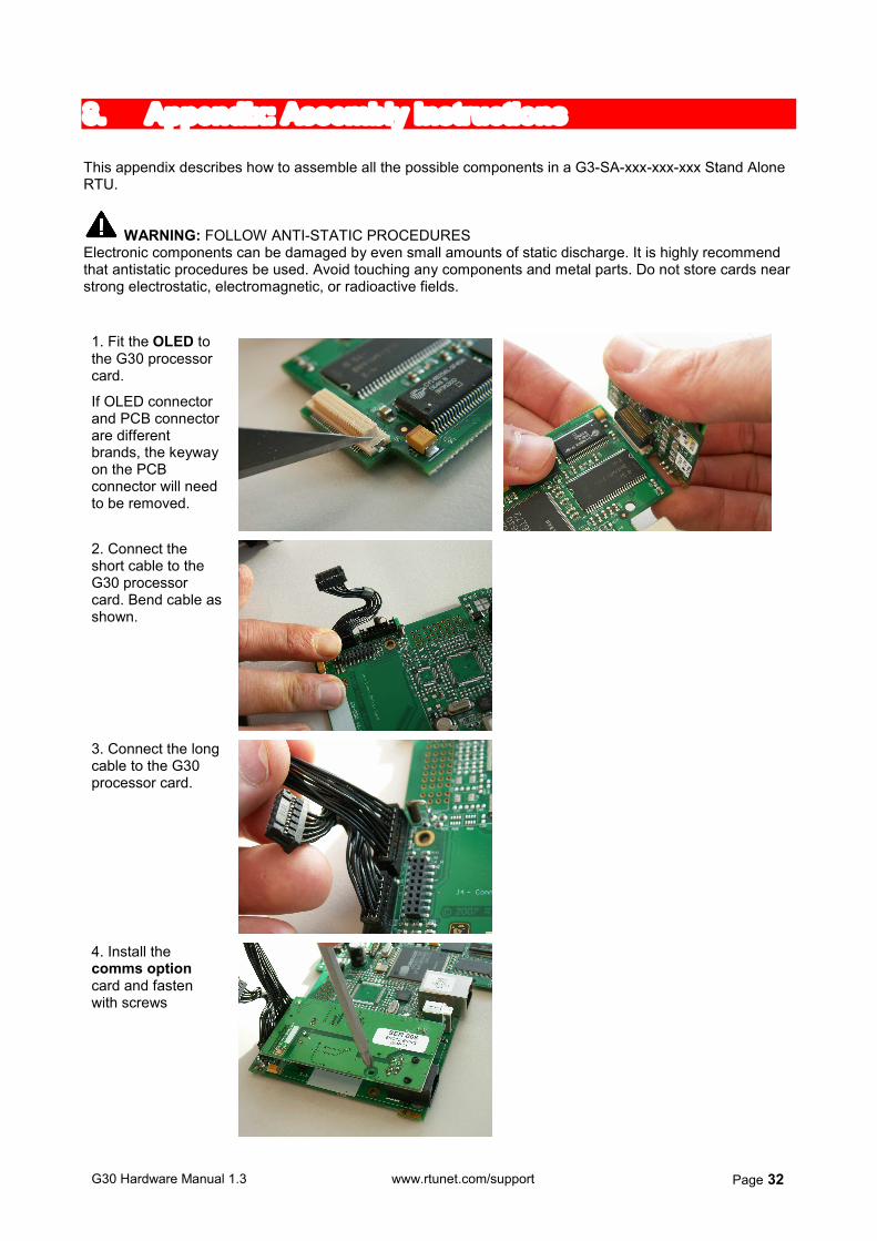
WARNING: FOLLOW ANTI-STATIC PROCEDURES Electronic components can be damaged by even small amounts of static discharge. It is highly recommend that antistatic procedures be used. Avoid touching any components and metal parts. Do not store cards near strong electrostatic, electromagnetic, or radioactive fields. 1. Fit the OLED to the G30 processor card.
If OLED connector and PCB connector are different brands, the keyway on the PCB connector will need to be removed.
2. Connect the short cable to the G30 processor card. Bend cable as shown.
3. Connect the long cable to the G30 processor card.
4. Install the comms option card and fasten with screws
G30 Hardware Manual 1.3 www.rtunet.com/support Page 33
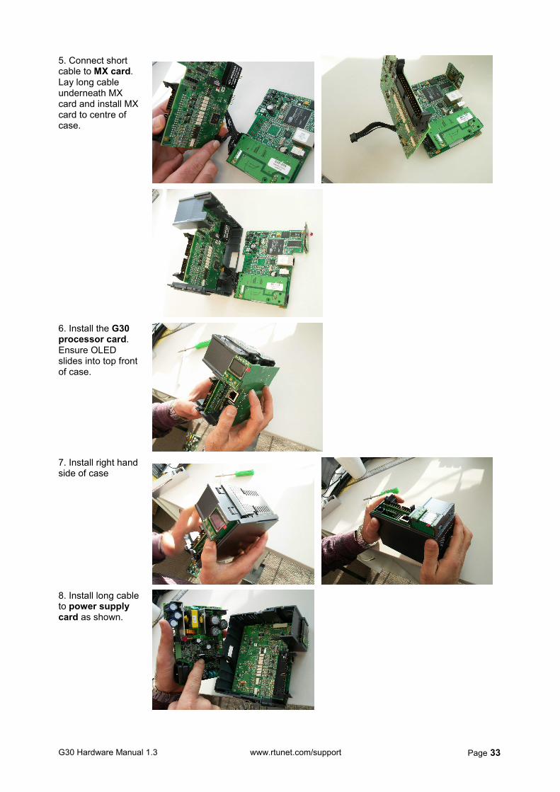
5. Connect short cable to MX card. Lay long cable underneath MX card and install MX card to centre of case.
6. Install the G30 processor card. Ensure OLED slides into top front of case.
7. Install right hand side of case
8. Install long cable to power supply card as shown.
G30 Hardware Manual 1.3 www.rtunet.com/support Page 34
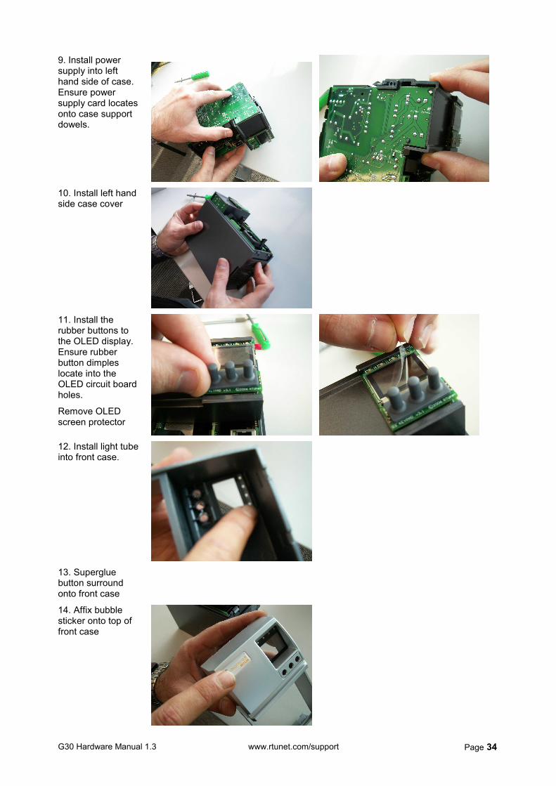
9. Install power supply into left hand side of case. Ensure power supply card locates onto case support dowels.
10. Install left hand side case cover
11. Install the rubber buttons to the OLED display. Ensure rubber button dimples locate into the OLED circuit board holes.
Remove OLED screen protector
12. Install light tube into front case.
13. Superglue button surround onto front case
14. Affix bubble sticker onto top of front case
G30 Hardware Manual 1.3 www.rtunet.com/support Page 35
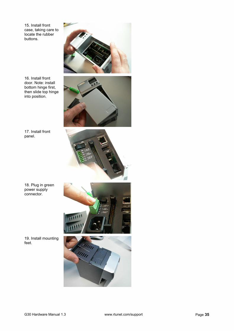
15. Install front case, taking care to locate the rubber buttons.
16. Install front door. Note: install bottom hinge first, then slide top hinge into position.
17. Install front panel.
18. Plug in green power supply connector.
19. Install mounting feet.
G30 Hardware Manual 1.3 www.rtunet.com/support Page 36
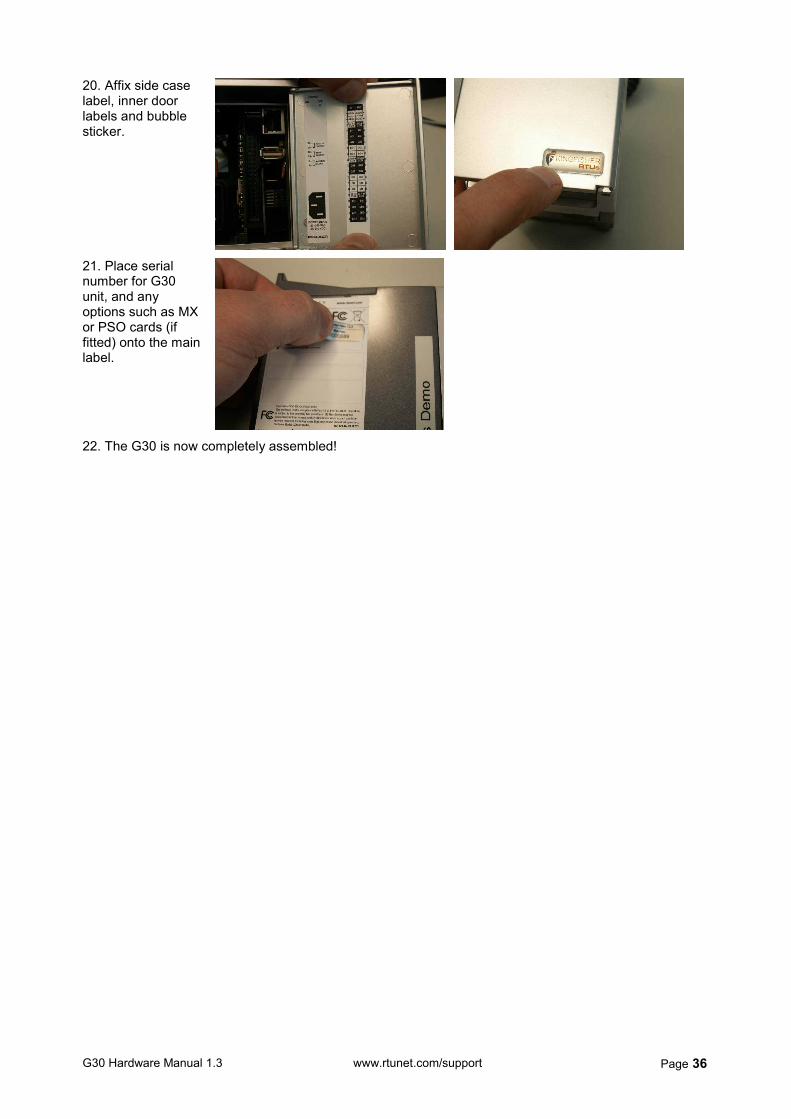
20. Affix side case label, inner door labels and bubble sticker.
21. Place serial number for G30 unit, and any options such as MX or PSO cards (if fitted) onto the main label.
22. The G30 is now completely assembled!


