88
Flappy Bird CSEE 4840 Embedded system design Wei Zheng wz2299 Gaoyuan Zhang gz2216 Junhui Zhang jz2605 Yen Hsi Lin yl3284
Flappy Bird CSEE 4840 Embedded system design
Wei Zheng wz2299 Gaoyuan Zhang gz2216 Junhui Zhang jz2605 Yen Hsi Lin yl3284

1
Contents
1. Overview ......................................................................................... 2
2. High Level Design ............................................................................ 3
3. Game Logic Controller ..................................................................... 4
4. Game stuff preparation .................................................................. 6
5. VGA Device Drive ............................................................................ 7
6. Sprite Controllers and VGA Display ................................................. 7
7. Audio ............................................................................................... 9
8. Lessons learned and issue ............................................................. 11
9. Advice and future work ................................................................. 11
10. Contribution ................................................................................ 11
11. Milestone .................................................................................... 12
12.Verilog HDL Code ......................................................................... 13
13. C Code ......................................................................................... 70

2
1. Overview
In this project, we design and implement a Flappy Bird like video game on the SoCKit development board. Flappy Bird is a very popular mobile game on Android platform, driving a lot of people crazy. In this game, the player can control the vertical movement of bird ( every pressing on the keyboard makes the bird leap upward for a little bit, and the bird will fall freely without control ). As soon as the game begins, tubes will keep appearing from the right side of the screen and moving leftwards. (so that it seems like the bird flying forward). The goal of this game is to control the bird, dodging and passing the incoming tubes, as many as possible. The game is endless until the bird eventually hit one of the tubes, ground, or ceiling. Figure 1 is the start screen of Flappy Bird. The title "Flappy Bird" is shown in the middle of the uppers side of the screen. The bird is also displayed on the background.
Figure 1. Start screen for Flappy Bird Figure 2 shows the screen when the game is on. The three pillars are displayed on the screen, and so is the score, on top of the background or the pillar. (instead of the title)
Figure 2. Game-‐on screen for Flappy Bird

3
2. High Level Design
Primary components that constitutes our game includes the ARM core (game logic), device driver, USB controller to control the input from keyboard, Sprite controller (control the display of sprites), audio controller, SDRAM ( store all the data needed in game logic). The game logic module interfaces with several other modules including the USB keyboard, by receiving the control signal; as well as the device driver in order to control the audio and display of sprites, including the positions of pillars and birds, the length of the pillars and the score. Sprite controller is connected to VGA Controller, which is responsible for the display of all the images, and audio controller is connected to audio CODEC on the SoCKit board. Each of the components in our design will be discussed in detail below.
Figure 3. High level block diagram

4
3. Game Logic Controller
We implement the game logic by using C programming language. The game logic controller should realize the functions which are indicated below: updating the location of the bird from the keyboard, implementing the game rule (whether the game is over or not, computing how many pillars the bird has passed), generating the appropriate audio in terms of the game rule, and controlling the generation of sprites. Based on the functions given above, there should be 3 submodules for the game logic controller, the figure of which is shown below:
Figure 4. Game logic block diagram 1. Game rules: This is the core submodule of the game logic controller which interfaces with all of the other submodules, instructing them what to do based on the game rules. The rules are implemented by the updated position of bird from the keyboard, and the current position of the pillars. Appropriate audio is chosen corresponding to the rules (whether the game is over or not). 2. Sprite generator:
1. Pillars: This submodule keeps updating the X coordinates of the pillars that has already appeared on the screen (by decrementing them in every cycle), as well as the length of the upcoming pillar that is going to appear from the right side of the screen (which is actually the number of "partial" pillars that stack). The length of the pillar should be random, as long as the distance between the pillars is constant. Once the sprite moves out of the screen (in this case, x coordinate of any one of the pillars becomes zero), we reset the coordinate so that it can reappear from the right side of the screen. 2. Bird: Bird acts like in real world that its jump and fall will be affect by the gravity. When

5
we implement the object motion formula in our code, time calculation is an issue that we use a counter counting instead of using system clock. We put the delay in our loop and try a suitable count number being our time unit. In addition, we add a status variable to indicate if the bird status is rising or falling. It cooperates with our jumping and falling function with iteration loop supporting continuous jumping without multi-‐thread. 3. Score: Every time the bird passes one of the pillars, the "Game Rules" submodule sends a signal, which will make the score increment by 1. Since the sprite for displaying the score are separated into 3 parts, hundreds, tens and digits, we need to extract them from the score before sending them to the hardware. 4. Title: The display of the title "Flappy Bird" depends on whether the game starts. When the game is over, press "enter" to restart, and the title would be displayed instantly. Since each signal sent from software to hardware has 8 bits, we only use one of them as the control signal to display the title, so that we can use other bits for other purposes, which improve efficiency.
3. Audio generator: There are three audios to be played, one played once pressing the "jump" button, and two played consecutively once the game is over. The selection of the audio is based on the signals from "Game Rule" submodule.

6
4. Game stuff preparation
The preparations required for the graphics and audio are similar. First the image and audio files had to be searched for online. Once we agreed on the images and audio for the game, we edited them to fit our game design. Finally, both the image and audio files had to be converted to MIF format in order to be stored in the on-‐chip ROM blocks.
Image preparation
For image preparation, first we resize the image to the size we will use. Then we do image segmentation of the images to separate the useful part. Then we set the background to a pure color so that the sprite controller can easily recognize the background part and remove it. Finally we convert the processed image to MIF files. In FPGA we will use different module to read the data of the MIF files. The image we processed is showed below.
Blocks background bird number Pipe sun Numbers 1 1 10 2 1 Pixels 128*64 40*40 51*33 20*125 50*50 ROM size(bytes)
24567 4800 1683 2500 7500
example
Audio preparation
For audio preparation, it is familiar as the image processing. In this game, we totally used three sound segment: Super Mario jumping sound, Super Mario death sound and Doodle Jump falling down sound. For Super Mario death sound, it is a segment with 22050 Hz sampling rate and 65536 samples. The codec sampling rate of FPGA we use is 44100 Hz. So we first upsample the sound segment by a factor of 2. Then it becomes a segment of 131072 samples. The maximum of MegaWizard ROM words is 65536. Thus we should divide the segment into two parts each of them consists 65535 samples. Then convert them into MIF files. The process of jumping sound and falling down sound is same as the death sound.
7
5. VGA Device Drive
The VGA module is actually a memory-‐mapped slave, which connects to the Avalon bus through the lightweight AXI bridge. The HPS uses 4-‐bit address bits to access 16 location that store 8 bits data. More specifically, The software use ioctl to call the iowrite function in the device driver and specify the registers’ address(a base address of the vga slave plus the offset address which is specified in the device tree ) to write. We use Qsys to connect everything between vga_led and the HPS up.
6. Sprite Controllers and VGA Display
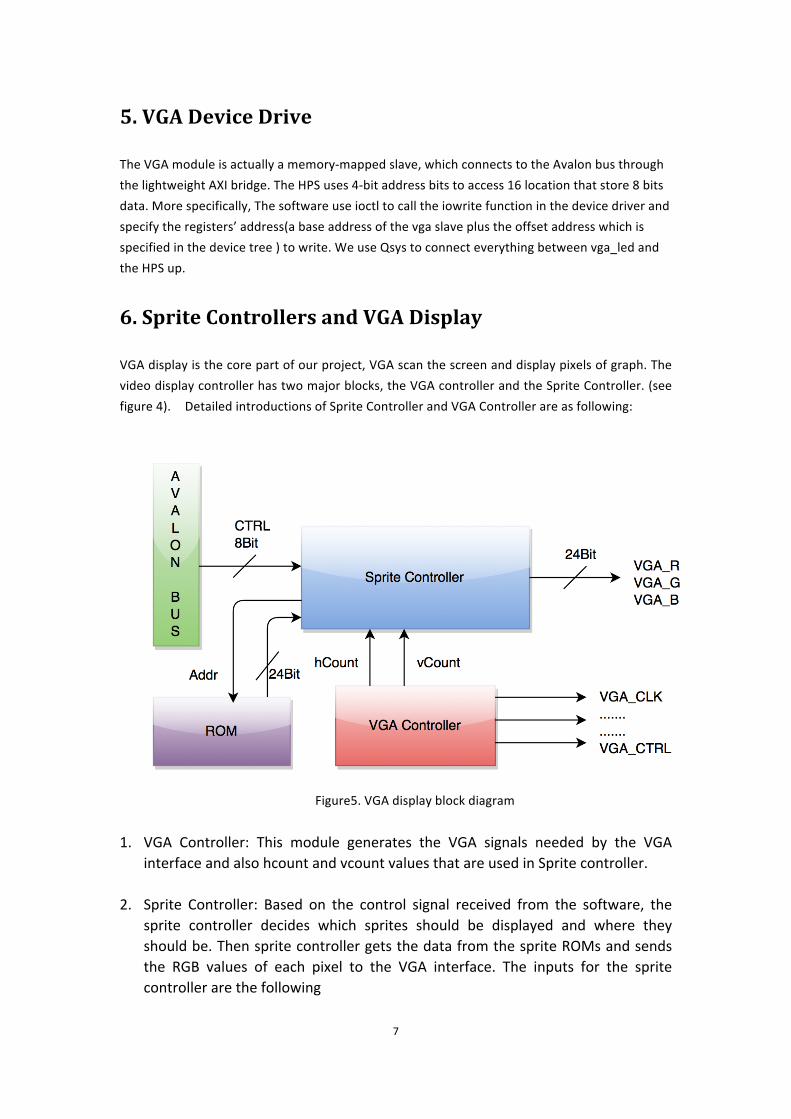
VGA display is the core part of our project, VGA scan the screen and display pixels of graph. The video display controller has two major blocks, the VGA controller and the Sprite Controller. (see figure 4). Detailed introductions of Sprite Controller and VGA Controller are as following:
Figure5. VGA display block diagram
1. VGA Controller: This module generates the VGA signals needed by the VGA interface and also hcount and vcount values that are used in Sprite controller.
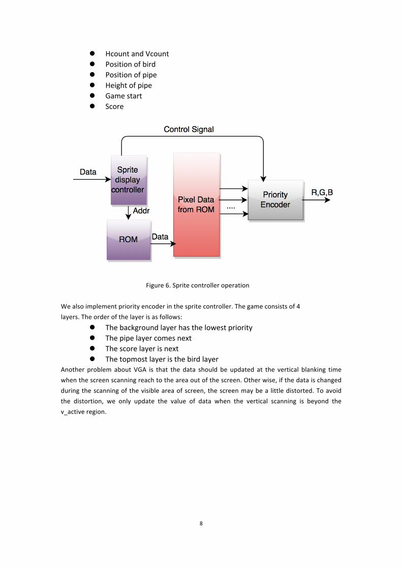
2. Sprite Controller: Based on the control signal received from the software, the sprite controller decides which sprites should be displayed and where they should be. Then sprite controller gets the data from the sprite ROMs and sends the RGB values of each pixel to the VGA interface. The inputs for the sprite controller are the following
8
l Hcount and Vcount l Position of bird l Position of pipe l Height of pipe l Game start l Score
Figure 6. Sprite controller operation We also implement priority encoder in the sprite controller. The game consists of 4 layers. The order of the layer is as follows:
l The background layer has the lowest priority l The pipe layer comes next l The score layer is next l The topmost layer is the bird layer
Another problem about VGA is that the data should be updated at the vertical blanking time when the screen scanning reach to the area out of the screen. Other wise, if the data is changed during the scanning of the visible area of screen, the screen may be a little distorted. To avoid the distortion, we only update the value of data when the vertical scanning is beyond the v_active region.

9
7. Audio
The SoCKit board supports 24-‐bit audio with the Analog Devices SSM2603 audio codec. SSM2603 has ports for microphone in, line in, and line out. The sampling rate supported is 8 KHz to 96 KHz and is adjustable. Flappy bird supports sound for bird jumping and gameover music. The audio controller has 3 main components: 1) Audio Data, 2) Audio codec configuration interface 3) Digital audio interface. We use three sound files in this game. First we convert them to memory initialization file format. These .mif files for the jumping sound (jumping.mif), dead sound (dead.mif) and the falling down sound (death.mif) are used to create ROM data blocks using megawizard. Jumping and falling down music ROM blocks contain 32768 16-‐bit audio samples and dead sound ROM block contains 65536 16-‐bit audio samples. The total size of the memory used for audio storage is 128KB. Audio Codec Configuration Interface is used to configure the various parameters inside the SSM2603 audio codec. This interface uses the I2C protocol to communicate the configuration parameters to the audio codec. Some of the configured parameters are: volume (which is set to 0 dB), the mode of the audio codec (which is set to slave), sampling rate (we are using 44.1 kHz), power on and off the audio codec, etc. Digital Audio Interface has two sub-‐components: a) Audio sample fetch and b) Audio codec interface. Both of these sub-‐components operate at the audio clock rate (11.3 MHz), which is derived from the reference clock (50 MHz) using Phase Locked Loop (PLL). The complete block diagram is shown below.
Figure 7. The block diagram of the audio controller.

10
The audio sample fetch is used to get the 16-‐bit audio samples from the Audio ROM blocks, which are accessed using the address bits for the blocks. The fetch unit also takes control as input, which comes from the audio peripheral module in software. This control signal is used to control the switching on and off of the jumping and dead sound. The Audio codec interface sub-‐component sends audio samples to the audio codec using shift registers, that shift these samples at fixed clock rate. The audio clock is used to derive two audio clocks: (i) Left Right Channel (LRC) clock and (ii) Bit clock. Both these clocks are generated from the audio clock using clock divider. The LRC clock is used for time multiplexing the audio samples. The audio sample can be sent out on the positive phase (left channel) of the clock or negative phase (right channel). The bit clock is used to send each bit of the audio sample as shown by the timing diagram in Figure 7. Please note as there are many number of cycles in one phase of the LRC clock, the codec interface sends don’t cares for the remaining cycles are after transmitting 16 bits of the audio sample.
Figure 8. The timing diagram of the audio sample.

11
8. Lessons learned and issue
l The biggest issue is the USB input driver. The kernel in our SoCKit board can’t read USB driver library even we update and install the library. We do some modification and using lab2 to environment to make our keyboard work. We also modify bit-‐width in driver to communicate with SoCKit board collaborate with our signal.
l Second issue is synchronization between loop in software and frame buffer update in hardware. We need to update the object position when the frame is not showed on the screen. So we update the screen only when it scans to the bottom of the screen.
l Bird motion need time variable which is not straightforward to get. Because the data type we get from system clock is not available for calculation. We build a counter to simulate our time instead of using system clock.
l We also discuss about how to precisely eliminate the redundant background in sprites. It could be simple if there is only one color in background: we determine the RGB value of the background using matlab, and eliminating the background by avoiding the point with such RGB value in the sprite. If there are multiple colors then we don’t have an efficient way.
9. Advice and future work
• Improve our coding style. In our hardware coding, we unroll the program without making it hierarchical as a module which may lead to difficulty for debugging.
• Choose high resolution sprite pictures and eliminating sprite background more clearly can make our game picture looks better.
• Design more complex game logic can increase our game integrity. Fro example, background changes with time, distance between pillar become random.
10. Contribution
Yen Hsi Lin: Sprite conversion, part of sprite controller, part of game logic Junhui Zhang: part of sprite controller, part of game logic, hardware implementation Wei Zheng: Audio setup, Linux driver, part of sprite controller, part of game logic Gaoyuan Zhang: Image and audio processing, audio setup, Linux driver, part of sprite controller

12
11. Milestone
Date Accomplishment Milestone1 4/2 Sprite controller and HDL program framework completed. Game picture
includes background and bird complete Milestone2 4/14 Continue our sprite control in hardware.
Complete design and program for game logic including bird movement, pillar generation and boundary condition.
Milestone3 4/28 Complete audio component setup in sockit board, USB and keyboard driver.
Deadline 5/14 Fix the frame signal synchronization between software and hardware. Optimize sprites and game logic.
13
12.Verilog HDL Code
SoCKit_top.v //
=====================================================================
=======
// Copyright (c) 2013 by Terasic Technologies Inc.
//
=====================================================================
=======
//
// Permission:
//
// Terasic grants permission to use and modify this code for use
// in synthesis for all Terasic Development Boards and Altera
Development
// Kits made by Terasic. Other use of this code, including the selling
// ,duplication, or modification of any portion is strictly prohibited.
//
// Disclaimer:
//
// This VHDL/Verilog or C/C++ source code is intended as a design
reference
// which illustrates how these types of functions can be implemented.
// It is the user's responsibility to verify their design for
// consistency and functionality through the use of formal
// verification methods. Terasic provides no warranty regarding the use
// or functionality of this code.
//
//
=====================================================================
=======
//
// Terasic Technologies Inc
// 9F., No.176, Sec.2, Gongdao 5th Rd, East Dist, Hsinchu City, 30070.
Taiwan
//
//
// web: http://www.terasic.com/
// email: [email protected]
//
//
=====================================================================
=======

14
//
=====================================================================
=======
//
// Major Functions: SoCKit_Default
//
//
=====================================================================
=======
// Revision History :
//
=====================================================================
=======
// Ver :| Author :| Mod. Date :| Changes Made:
// V1.0 :| xinxian :| 04/02/13 :| Initial Revision
//
=====================================================================
=======
//`define ENABLE_DDR3
//`define ENABLE_HPS
//`define ENABLE_HSMC_XCVR
module SoCKit_Top(
///////////AUD/////////////
AUD_ADCDAT,
AUD_ADCLRCK,
AUD_BCLK,
AUD_DACDAT,
AUD_DACLRCK,
AUD_I2C_SCLK,
AUD_I2C_SDAT,
AUD_MUTE,
AUD_XCK,
`ifdef ENABLE_DDR3
/////////DDR3/////////
DDR3_A,
DDR3_BA,
DDR3_CAS_n,
DDR3_CKE,
DDR3_CK_n,
DDR3_CK_p,
15
DDR3_CS_n,
DDR3_DM,
DDR3_DQ,
DDR3_DQS_n,
DDR3_DQS_p,
DDR3_ODT,
DDR3_RAS_n,
DDR3_RESET_n,
DDR3_RZQ,
DDR3_WE_n,
`endif /*ENABLE_DDR3*/
/////////FAN/////////
FAN_CTRL,
`ifdef ENABLE_HPS
/////////HPS/////////
HPS_CLOCK_25,
HPS_CLOCK_50,
HPS_CONV_USB_n,
HPS_DDR3_A,
HPS_DDR3_BA,
HPS_DDR3_CAS_n,
HPS_DDR3_CKE,
HPS_DDR3_CK_n,
HPS_DDR3_CK_p,
HPS_DDR3_CS_n,
HPS_DDR3_DM,
HPS_DDR3_DQ,
HPS_DDR3_DQS_n,
HPS_DDR3_DQS_p,
HPS_DDR3_ODT,
HPS_DDR3_RAS_n,
HPS_DDR3_RESET_n,
HPS_DDR3_RZQ,
HPS_DDR3_WE_n,
HPS_ENET_GTX_CLK,
HPS_ENET_INT_n,
HPS_ENET_MDC,
HPS_ENET_MDIO,
HPS_ENET_RESET_n,
HPS_ENET_RX_CLK,
HPS_ENET_RX_DATA,
HPS_ENET_RX_DV,

16
HPS_ENET_TX_DATA,
HPS_ENET_TX_EN,
HPS_FLASH_DATA,
HPS_FLASH_DCLK,
HPS_FLASH_NCSO,
HPS_GSENSOR_INT,
HPS_I2C_CLK,
HPS_I2C_SDA,
HPS_KEY,
HPS_LCM_D_C,
HPS_LCM_RST_N,
HPS_LCM_SPIM_CLK,
HPS_LCM_SPIM_MISO,
HPS_LCM_SPIM_MOSI,
HPS_LCM_SPIM_SS,
HPS_LED,
HPS_LTC_GPIO,
HPS_RESET_n,
HPS_SD_CLK,
HPS_SD_CMD,
HPS_SD_DATA,
HPS_SPIM_CLK,
HPS_SPIM_MISO,
HPS_SPIM_MOSI,
HPS_SPIM_SS,
HPS_SW,
HPS_UART_RX,
HPS_UART_TX,
HPS_USB_CLKOUT,
HPS_USB_DATA,
HPS_USB_DIR,
HPS_USB_NXT,
HPS_USB_RESET_PHY,
HPS_USB_STP,
HPS_WARM_RST_n,
`endif /*ENABLE_HPS*/
/////////HSMC/////////
HSMC_CLKIN_n,
HSMC_CLKIN_p,
HSMC_CLKOUT_n,
HSMC_CLKOUT_p,
HSMC_CLK_IN0,
HSMC_CLK_OUT0,

17
HSMC_D,
`ifdef ENABLE_HSMC_XCVR
HSMC_GXB_RX_p,
HSMC_GXB_TX_p,
HSMC_REF_CLK_p,
`endif
HSMC_RX_n,
HSMC_RX_p,
HSMC_SCL,
HSMC_SDA,
HSMC_TX_n,
HSMC_TX_p,
/////////IRDA/////////
IRDA_RXD,
/////////KEY/////////
KEY,
/////////LED/////////
// LED,
/////////OSC/////////
OSC_50_B3B,
OSC_50_B4A,
OSC_50_B5B,
OSC_50_B8A,
/////////PCIE/////////
PCIE_PERST_n,
PCIE_WAKE_n,
/////////RESET/////////
RESET_n,
/////////SI5338/////////
SI5338_SCL,
SI5338_SDA,
/////////SW/////////
SW,
18
/////////TEMP/////////
TEMP_CS_n,
TEMP_DIN,
TEMP_DOUT,
TEMP_SCLK,
/////////USB/////////
USB_B2_CLK,
USB_B2_DATA,
USB_EMPTY,
USB_FULL,
USB_OE_n,
USB_RD_n,
USB_RESET_n,
USB_SCL,
USB_SDA,
USB_WR_n,
/////////VGA/////////
VGA_B,
VGA_BLANK_n,
VGA_CLK,
VGA_G,
VGA_HS,
VGA_R,
VGA_SYNC_n,
VGA_VS,
///////////hps//////////
memory_mem_a,
memory_mem_ba,
memory_mem_ck,
memory_mem_ck_n,
memory_mem_cke,
memory_mem_cs_n,
memory_mem_ras_n,
memory_mem_cas_n,
memory_mem_we_n,
memory_mem_reset_n,
memory_mem_dq,
memory_mem_dqs,
memory_mem_dqs_n,
memory_mem_odt,
memory_mem_dm,
memory_oct_rzqin,
19
hps_io_hps_io_emac1_inst_TX_CLK,
hps_io_hps_io_emac1_inst_TXD0,
hps_io_hps_io_emac1_inst_TXD1,
hps_io_hps_io_emac1_inst_TXD2,
hps_io_hps_io_emac1_inst_TXD3,
hps_io_hps_io_emac1_inst_RXD0,
hps_io_hps_io_emac1_inst_MDIO,
hps_io_hps_io_emac1_inst_MDC,
hps_io_hps_io_emac1_inst_RX_CTL,
hps_io_hps_io_emac1_inst_TX_CTL,
hps_io_hps_io_emac1_inst_RX_CLK,
hps_io_hps_io_emac1_inst_RXD1,
hps_io_hps_io_emac1_inst_RXD2,
hps_io_hps_io_emac1_inst_RXD3,
hps_io_hps_io_qspi_inst_IO0,
hps_io_hps_io_qspi_inst_IO1,
hps_io_hps_io_qspi_inst_IO2,
hps_io_hps_io_qspi_inst_IO3,
hps_io_hps_io_qspi_inst_SS0,
hps_io_hps_io_qspi_inst_CLK,
hps_io_hps_io_sdio_inst_CMD,
hps_io_hps_io_sdio_inst_D0,
hps_io_hps_io_sdio_inst_D1,
hps_io_hps_io_sdio_inst_CLK,
hps_io_hps_io_sdio_inst_D2,
hps_io_hps_io_sdio_inst_D3,
hps_io_hps_io_usb1_inst_D0,
hps_io_hps_io_usb1_inst_D1,
hps_io_hps_io_usb1_inst_D2,
hps_io_hps_io_usb1_inst_D3,
hps_io_hps_io_usb1_inst_D4,
hps_io_hps_io_usb1_inst_D5,
hps_io_hps_io_usb1_inst_D6,
hps_io_hps_io_usb1_inst_D7,
hps_io_hps_io_usb1_inst_CLK,
hps_io_hps_io_usb1_inst_STP,
hps_io_hps_io_usb1_inst_DIR,
hps_io_hps_io_usb1_inst_NXT,
hps_io_hps_io_spim0_inst_CLK,
hps_io_hps_io_spim0_inst_MOSI,
hps_io_hps_io_spim0_inst_MISO,
hps_io_hps_io_spim0_inst_SS0,
hps_io_hps_io_spim1_inst_CLK,
hps_io_hps_io_spim1_inst_MOSI,

20
hps_io_hps_io_spim1_inst_MISO,
hps_io_hps_io_spim1_inst_SS0,
hps_io_hps_io_uart0_inst_RX,
hps_io_hps_io_uart0_inst_TX,
hps_io_hps_io_i2c1_inst_SDA,
hps_io_hps_io_i2c1_inst_SCL,
hps_io_hps_io_gpio_inst_GPIO00
);
//=======================================================
// PORT declarations
//=======================================================
///////// AUD /////////
input AUD_ADCDAT;
inout AUD_ADCLRCK;
inout AUD_BCLK;
output AUD_DACDAT;
inout AUD_DACLRCK;
output AUD_I2C_SCLK;
inout AUD_I2C_SDAT;
output AUD_MUTE;
output AUD_XCK;
`ifdef ENABLE_DDR3
///////// DDR3 /////////
output [14:0] DDR3_A;
output [2:0] DDR3_BA;
output DDR3_CAS_n;
output DDR3_CKE;
output DDR3_CK_n;
output DDR3_CK_p;
output DDR3_CS_n;
output [3:0] DDR3_DM;
inout [31:0] DDR3_DQ;
inout [3:0] DDR3_DQS_n;
inout [3:0] DDR3_DQS_p;
output DDR3_ODT;
output DDR3_RAS_n;
output DDR3_RESET_n;
input DDR3_RZQ;
output DDR3_WE_n;
`endif /*ENABLE_DDR3*/
21
///////// FAN /////////
output FAN_CTRL;
`ifdef ENABLE_HPS
///////// HPS /////////
input HPS_CLOCK_25;
input HPS_CLOCK_50;
input HPS_CONV_USB_n;
output [14:0] HPS_DDR3_A;
output [2:0] HPS_DDR3_BA;
output HPS_DDR3_CAS_n;
output HPS_DDR3_CKE;
output HPS_DDR3_CK_n;
output HPS_DDR3_CK_p;
output HPS_DDR3_CS_n;
output [3:0] HPS_DDR3_DM;
inout [31:0] HPS_DDR3_DQ;
inout [3:0] HPS_DDR3_DQS_n;
inout [3:0] HPS_DDR3_DQS_p;
output HPS_DDR3_ODT;
output HPS_DDR3_RAS_n;
output HPS_DDR3_RESET_n;
input HPS_DDR3_RZQ;
output HPS_DDR3_WE_n;
input HPS_ENET_GTX_CLK;
input HPS_ENET_INT_n;
output HPS_ENET_MDC;
inout HPS_ENET_MDIO;
output HPS_ENET_RESET_n;
input HPS_ENET_RX_CLK;
input [3:0] HPS_ENET_RX_DATA;
input HPS_ENET_RX_DV;
output [3:0] HPS_ENET_TX_DATA;
output HPS_ENET_TX_EN;
inout [3:0] HPS_FLASH_DATA;
output HPS_FLASH_DCLK;
output HPS_FLASH_NCSO;
input HPS_GSENSOR_INT;
inout HPS_I2C_CLK;
inout HPS_I2C_SDA;
inout [3:0] HPS_KEY;
output HPS_LCM_D_C;
output HPS_LCM_RST_N;
input HPS_LCM_SPIM_CLK;
22
inout HPS_LCM_SPIM_MISO;
output HPS_LCM_SPIM_MOSI;
output HPS_LCM_SPIM_SS;
output [3:0] HPS_LED;
inout HPS_LTC_GPIO;
input HPS_RESET_n;
output HPS_SD_CLK;
inout HPS_SD_CMD;
inout [3:0] HPS_SD_DATA;
output HPS_SPIM_CLK;
input HPS_SPIM_MISO;
output HPS_SPIM_MOSI;
output HPS_SPIM_SS;
input [3:0] HPS_SW;
input HPS_UART_RX;
output HPS_UART_TX;
input HPS_USB_CLKOUT;
inout [7:0] HPS_USB_DATA;
input HPS_USB_DIR;
input HPS_USB_NXT;
output HPS_USB_RESET_PHY;
output HPS_USB_STP;
input HPS_WARM_RST_n;
`endif /*ENABLE_HPS*/
///////// HSMC /////////
input [2:1] HSMC_CLKIN_n;
input [2:1] HSMC_CLKIN_p;
output [2:1] HSMC_CLKOUT_n;
output [2:1] HSMC_CLKOUT_p;
input HSMC_CLK_IN0;
output HSMC_CLK_OUT0;
inout [3:0] HSMC_D;
`ifdef ENABLE_HSMC_XCVR
input [7:0] HSMC_GXB_RX_p;
output [7:0] HSMC_GXB_TX_p;
input HSMC_REF_CLK_p;
`endif
inout [16:0] HSMC_RX_n;
inout [16:0] HSMC_RX_p;
output HSMC_SCL;
inout HSMC_SDA;
inout [16:0] HSMC_TX_n;
inout [16:0] HSMC_TX_p;

23
///////// IRDA /////////
input IRDA_RXD;
///////// KEY /////////
input [3:0] KEY;
///////// LED /////////
// output [3:0] LED;
///////// OSC /////////
input OSC_50_B3B;
input OSC_50_B4A;
input OSC_50_B5B;
input OSC_50_B8A;
///////// PCIE /////////
input PCIE_PERST_n;
input PCIE_WAKE_n;
///////// RESET /////////
input RESET_n;
///////// SI5338 /////////
inout SI5338_SCL;
inout SI5338_SDA;
///////// SW /////////
input [3:0] SW;
///////// TEMP /////////
output TEMP_CS_n;
output TEMP_DIN;
input TEMP_DOUT;
output TEMP_SCLK;
///////// USB /////////
input USB_B2_CLK;
inout [7:0] USB_B2_DATA;
output USB_EMPTY;
output USB_FULL;
input USB_OE_n;
input USB_RD_n;
input USB_RESET_n;

24
inout USB_SCL;
inout USB_SDA;
input USB_WR_n;
///////// VGA /////////
output [7:0] VGA_B;
output VGA_BLANK_n;
output VGA_CLK;
output [7:0] VGA_G;
output VGA_HS;
output [7:0] VGA_R;
output VGA_SYNC_n;
output VGA_VS;
/////////hps pin///////
output wire [14:0] memory_mem_a;
output wire [2:0] memory_mem_ba;
output wire memory_mem_ck;
output wire memory_mem_ck_n;
output wire memory_mem_cke;
output wire memory_mem_cs_n;
output wire memory_mem_ras_n;
output wire memory_mem_cas_n;
output wire memory_mem_we_n;
output wire memory_mem_reset_n;
inout wire [31:0] memory_mem_dq;
inout wire [3:0] memory_mem_dqs;
inout wire [3:0] memory_mem_dqs_n;
output wire memory_mem_odt;
output wire [3:0] memory_mem_dm;
input wire memory_oct_rzqin;
output wire hps_io_hps_io_emac1_inst_TX_CLK;
output wire hps_io_hps_io_emac1_inst_TXD0;
output wire hps_io_hps_io_emac1_inst_TXD1;
output wire hps_io_hps_io_emac1_inst_TXD2;
output wire hps_io_hps_io_emac1_inst_TXD3;
input wire hps_io_hps_io_emac1_inst_RXD0;
inout wire hps_io_hps_io_emac1_inst_MDIO;
output wire hps_io_hps_io_emac1_inst_MDC;
input wire hps_io_hps_io_emac1_inst_RX_CTL;
output wire hps_io_hps_io_emac1_inst_TX_CTL;
input wire hps_io_hps_io_emac1_inst_RX_CLK;
input wire hps_io_hps_io_emac1_inst_RXD1;
input wire hps_io_hps_io_emac1_inst_RXD2;

25
input wire hps_io_hps_io_emac1_inst_RXD3;
inout wire hps_io_hps_io_qspi_inst_IO0;
inout wire hps_io_hps_io_qspi_inst_IO1;
inout wire hps_io_hps_io_qspi_inst_IO2;
inout wire hps_io_hps_io_qspi_inst_IO3;
output wire hps_io_hps_io_qspi_inst_SS0;
output wire hps_io_hps_io_qspi_inst_CLK;
inout wire hps_io_hps_io_sdio_inst_CMD;
inout wire hps_io_hps_io_sdio_inst_D0;
inout wire hps_io_hps_io_sdio_inst_D1;
output wire hps_io_hps_io_sdio_inst_CLK;
inout wire hps_io_hps_io_sdio_inst_D2;
inout wire hps_io_hps_io_sdio_inst_D3;
inout wire hps_io_hps_io_usb1_inst_D0;
inout wire hps_io_hps_io_usb1_inst_D1;
inout wire hps_io_hps_io_usb1_inst_D2;
inout wire hps_io_hps_io_usb1_inst_D3;
inout wire hps_io_hps_io_usb1_inst_D4;
inout wire hps_io_hps_io_usb1_inst_D5;
inout wire hps_io_hps_io_usb1_inst_D6;
inout wire hps_io_hps_io_usb1_inst_D7;
input wire hps_io_hps_io_usb1_inst_CLK;
output wire hps_io_hps_io_usb1_inst_STP;
input wire hps_io_hps_io_usb1_inst_DIR;
input wire hps_io_hps_io_usb1_inst_NXT;
output wire hps_io_hps_io_spim0_inst_CLK;
output wire hps_io_hps_io_spim0_inst_MOSI;
input wire hps_io_hps_io_spim0_inst_MISO;
output wire hps_io_hps_io_spim0_inst_SS0;
output wire hps_io_hps_io_spim1_inst_CLK;
output wire hps_io_hps_io_spim1_inst_MOSI;
input wire hps_io_hps_io_spim1_inst_MISO;
output wire hps_io_hps_io_spim1_inst_SS0;
input wire hps_io_hps_io_uart0_inst_RX;
output wire hps_io_hps_io_uart0_inst_TX;
inout wire hps_io_hps_io_i2c1_inst_SDA;
inout wire hps_io_hps_io_i2c1_inst_SCL;
inout wire hps_io_hps_io_gpio_inst_GPIO00;
//=======================================================
// REG/WIRE declarations
//=======================================================
// For Audio CODEC
wire AUD_CTRL_CLK; // For Audio Controller

26
reg [31:0] Cont;
wire VGA_CTRL_CLK;
wire [9:0] mVGA_R;
wire [9:0] mVGA_G;
wire [9:0] mVGA_B;
wire [19:0] mVGA_ADDR;
wire DLY_RST;
// For VGA Controller
wire mVGA_CLK;
wire [9:0] mRed;
wire [9:0] mGreen;
wire [9:0] mBlue;
wire VGA_Read; // VGA data request
wire [9:0] recon_VGA_R;
wire [9:0] recon_VGA_G;
wire [9:0] recon_VGA_B;
// For Down Sample
wire [3:0] Remain;
wire [9:0] Quotient;
wire AUD_MUTE;
// Drive the LEDs with the switches
//assign LED = SW;
// Make the FPGA reset cause an HPS reset
reg [19:0] hps_reset_counter = 20'h0;
reg hps_fpga_reset_n = 0;
always @(posedge OSC_50_B4A) begin
if (hps_reset_counter == 20'h ffffff) hps_fpga_reset_n <= 1;
hps_reset_counter <= hps_reset_counter + 1;
end
lab3 u0 (
.clk_clk (OSC_50_B4A),
// clk.clk
.reset_reset_n (hps_fpga_reset_n),
// reset.reset_n
.memory_mem_a (memory_mem_a),

27
// memory.mem_a
.memory_mem_ba (memory_mem_ba),
// .mem_ba
.memory_mem_ck (memory_mem_ck),
// .mem_ck
.memory_mem_ck_n (memory_mem_ck_n),
// .mem_ck_n
.memory_mem_cke (memory_mem_cke),
// .mem_cke
.memory_mem_cs_n (memory_mem_cs_n),
// .mem_cs_n
.memory_mem_ras_n (memory_mem_ras_n),
// .mem_ras_n
.memory_mem_cas_n (memory_mem_cas_n),
// .mem_cas_n
.memory_mem_we_n (memory_mem_we_n),
// .mem_we_n
.memory_mem_reset_n (memory_mem_reset_n),
// .mem_reset_n
.memory_mem_dq (memory_mem_dq),
// .mem_dq
.memory_mem_dqs (memory_mem_dqs),
// .mem_dqs
.memory_mem_dqs_n (memory_mem_dqs_n),
// .mem_dqs_n
.memory_mem_odt (memory_mem_odt),
// .mem_odt
.memory_mem_dm (memory_mem_dm),
// .mem_dm
.memory_oct_rzqin (memory_oct_rzqin),
// .oct_rzqin
.hps_io_hps_io_emac1_inst_TX_CLK
(hps_io_hps_io_emac1_inst_TX_CLK), //
.hps_0_hps_io.hps_io_emac1_inst_TX_CLK
.hps_io_hps_io_emac1_inst_TXD0
(hps_io_hps_io_emac1_inst_TXD0),
// .hps_io_emac1_inst_TXD0
.hps_io_hps_io_emac1_inst_TXD1
(hps_io_hps_io_emac1_inst_TXD1),
// .hps_io_emac1_inst_TXD1
.hps_io_hps_io_emac1_inst_TXD2
(hps_io_hps_io_emac1_inst_TXD2),
// .hps_io_emac1_inst_TXD2
.hps_io_hps_io_emac1_inst_TXD3
28
(hps_io_hps_io_emac1_inst_TXD3),
// .hps_io_emac1_inst_TXD3
.hps_io_hps_io_emac1_inst_RXD0
(hps_io_hps_io_emac1_inst_RXD0),
// .hps_io_emac1_inst_RXD0
.hps_io_hps_io_emac1_inst_MDIO
(hps_io_hps_io_emac1_inst_MDIO),
// .hps_io_emac1_inst_MDIO
.hps_io_hps_io_emac1_inst_MDC
(hps_io_hps_io_emac1_inst_MDC),
// .hps_io_emac1_inst_MDC
.hps_io_hps_io_emac1_inst_RX_CTL
(hps_io_hps_io_emac1_inst_RX_CTL),
// .hps_io_emac1_inst_RX_CTL
.hps_io_hps_io_emac1_inst_TX_CTL
(hps_io_hps_io_emac1_inst_TX_CTL),
// .hps_io_emac1_inst_TX_CTL
.hps_io_hps_io_emac1_inst_RX_CLK
(hps_io_hps_io_emac1_inst_RX_CLK),
// .hps_io_emac1_inst_RX_CLK
.hps_io_hps_io_emac1_inst_RXD1
(hps_io_hps_io_emac1_inst_RXD1),
// .hps_io_emac1_inst_RXD1
.hps_io_hps_io_emac1_inst_RXD2
(hps_io_hps_io_emac1_inst_RXD2),
// .hps_io_emac1_inst_RXD2
.hps_io_hps_io_emac1_inst_RXD3
(hps_io_hps_io_emac1_inst_RXD3),
// .hps_io_emac1_inst_RXD3
.hps_io_hps_io_qspi_inst_IO0
(hps_io_hps_io_qspi_inst_IO0),
// .hps_io_qspi_inst_IO0
.hps_io_hps_io_qspi_inst_IO1
(hps_io_hps_io_qspi_inst_IO1),
// .hps_io_qspi_inst_IO1
.hps_io_hps_io_qspi_inst_IO2
(hps_io_hps_io_qspi_inst_IO2),
// .hps_io_qspi_inst_IO2
.hps_io_hps_io_qspi_inst_IO3
(hps_io_hps_io_qspi_inst_IO3),
// .hps_io_qspi_inst_IO3
.hps_io_hps_io_qspi_inst_SS0
(hps_io_hps_io_qspi_inst_SS0),
// .hps_io_qspi_inst_SS0

29
.hps_io_hps_io_qspi_inst_CLK
(hps_io_hps_io_qspi_inst_CLK),
// .hps_io_qspi_inst_CLK
.hps_io_hps_io_sdio_inst_CMD
(hps_io_hps_io_sdio_inst_CMD),
// .hps_io_sdio_inst_CMD
.hps_io_hps_io_sdio_inst_D0
(hps_io_hps_io_sdio_inst_D0),
// .hps_io_sdio_inst_D0
.hps_io_hps_io_sdio_inst_D1
(hps_io_hps_io_sdio_inst_D1),
// .hps_io_sdio_inst_D1
.hps_io_hps_io_sdio_inst_CLK
(hps_io_hps_io_sdio_inst_CLK),
// .hps_io_sdio_inst_CLK
.hps_io_hps_io_sdio_inst_D2
(hps_io_hps_io_sdio_inst_D2),
// .hps_io_sdio_inst_D2
.hps_io_hps_io_sdio_inst_D3
(hps_io_hps_io_sdio_inst_D3),
// .hps_io_sdio_inst_D3
.hps_io_hps_io_usb1_inst_D0
(hps_io_hps_io_usb1_inst_D0),
// .hps_io_usb1_inst_D0
.hps_io_hps_io_usb1_inst_D1
(hps_io_hps_io_usb1_inst_D1),
// .hps_io_usb1_inst_D1
.hps_io_hps_io_usb1_inst_D2
(hps_io_hps_io_usb1_inst_D2),
// .hps_io_usb1_inst_D2
.hps_io_hps_io_usb1_inst_D3
(hps_io_hps_io_usb1_inst_D3),
// .hps_io_usb1_inst_D3
.hps_io_hps_io_usb1_inst_D4
(hps_io_hps_io_usb1_inst_D4),
// .hps_io_usb1_inst_D4
.hps_io_hps_io_usb1_inst_D5
(hps_io_hps_io_usb1_inst_D5),
// .hps_io_usb1_inst_D5
.hps_io_hps_io_usb1_inst_D6
(hps_io_hps_io_usb1_inst_D6),
// .hps_io_usb1_inst_D6
.hps_io_hps_io_usb1_inst_D7
(hps_io_hps_io_usb1_inst_D7),

30
// .hps_io_usb1_inst_D7
.hps_io_hps_io_usb1_inst_CLK
(hps_io_hps_io_usb1_inst_CLK),
// .hps_io_usb1_inst_CLK
.hps_io_hps_io_usb1_inst_STP
(hps_io_hps_io_usb1_inst_STP),
// .hps_io_usb1_inst_STP
.hps_io_hps_io_usb1_inst_DIR
(hps_io_hps_io_usb1_inst_DIR),
// .hps_io_usb1_inst_DIR
.hps_io_hps_io_usb1_inst_NXT
(hps_io_hps_io_usb1_inst_NXT),
// .hps_io_usb1_inst_NXT
.hps_io_hps_io_spim0_inst_CLK
(hps_io_hps_io_spim0_inst_CLK),
// .hps_io_spim0_inst_CLK
.hps_io_hps_io_spim0_inst_MOSI
(hps_io_hps_io_spim0_inst_MOSI),
// .hps_io_spim0_inst_MOSI
.hps_io_hps_io_spim0_inst_MISO
(hps_io_hps_io_spim0_inst_MISO),
// .hps_io_spim0_inst_MISO
.hps_io_hps_io_spim0_inst_SS0
(hps_io_hps_io_spim0_inst_SS0),
// .hps_io_spim0_inst_SS0
.hps_io_hps_io_spim1_inst_CLK
(hps_io_hps_io_spim1_inst_CLK),
// .hps_io_spim1_inst_CLK
.hps_io_hps_io_spim1_inst_MOSI
(hps_io_hps_io_spim1_inst_MOSI),
// .hps_io_spim1_inst_MOSI
.hps_io_hps_io_spim1_inst_MISO
(hps_io_hps_io_spim1_inst_MISO),
// .hps_io_spim1_inst_MISO
.hps_io_hps_io_spim1_inst_SS0
(hps_io_hps_io_spim1_inst_SS0),
// .hps_io_spim1_inst_SS0
.hps_io_hps_io_uart0_inst_RX
(hps_io_hps_io_uart0_inst_RX),
// .hps_io_uart0_inst_RX
.hps_io_hps_io_uart0_inst_TX
(hps_io_hps_io_uart0_inst_TX),
// .hps_io_uart0_inst_TX
.hps_io_hps_io_i2c1_inst_SDA
31
(hps_io_hps_io_i2c1_inst_SDA),
// .hps_io_i2c1_inst_SDA
.hps_io_hps_io_i2c1_inst_SCL
(hps_io_hps_io_i2c1_inst_SCL) ,
// .hps_io_i2c1_inst_SCL
.vga_R (VGA_R),
.vga_G (VGA_G),
.vga_B (VGA_B),
.vga_CLK (VGA_CLK),
.vga_HS (VGA_HS),
.vga_VS (VGA_VS),
.vga_BLANK_n (VGA_BLANK_n),
.vga_SYNC_n (VGA_SYNC_n),
.vga_audio_ctrl (audio_ctrl_wire)
);
wire [1:0] audio_ctrl_wire;
Audio_top audios(
.OSC_50_B8A (OSC_50_B8A),
.AUD_ADCLRCK (AUD_ADCLRCK),
.AUD_ADCDAT (AUD_ADCDAT),
.AUD_DACLRCK (AUD_DACLRCK),
.AUD_DACDAT (AUD_DACDAT),
.AUD_XCK (AUD_XCK),
.AUD_BCLK (AUD_BCLK),
.AUD_I2C_SCLK (AUD_I2C_SCLK),
.AUD_I2C_SDAT (AUD_I2C_SDAT),
.AUD_MUTE (AUD_MUTE),
.KEY (KEY),
.SW (SW),
.LED (LED),
.audio_ctrl (audio_ctrl_wire)
);
endmodule
VGA_LED.sv /*
* Avalon memory-mapped peripheral for the VGA LED Emulator
*
32
* Stephen A. Edwards
* Columbia University
*/
module VGA_LED(input logic clk,
input logic reset,
input logic [7:0] writedata,
input logic write,
input chipselect,
input logic [3:0] address,
output logic [7:0] VGA_R, VGA_G, VGA_B,
output logic VGA_CLK, VGA_HS, VGA_VS, VGA_BLANK_n,
output logic VGA_SYNC_n,
output logic [1:0] VGA_audio_ctrl);
logic [15:0] center_h,center_v;
VGA_Emulator led_emulator(.clk50(clk), .reset(reset), .VGA_R(VGA_R),
.VGA_G(VGA_G), .VGA_B(VGA_B), .VGA_CLK(VGA_CLK), .VGA_HS(VGA_HS),
.VGA_VS(VGA_VS),
.VGA_BLANK_n(VGA_BLANK_n), .VGA_SYNC_n(VGA_SYNC_n), .loc_pillar1_
temp(xPillar1), .loc_pillar2_temp(xPillar2),
.loc_pillar3_temp(xPillar3), .len_pillars1_temp(hPillar1), .len_p
illars2_temp(hPillar2), .len_pillars3_temp(hPillar3),
.score_temp(score), .pos_bird_temp(bird), .start
_temp(start));
logic [15:0] xPillar1;
logic [15:0] xPillar2;
logic [15:0] xPillar3;
logic [7:0] hPillar1;
logic [7:0] hPillar2;
logic [7:0] hPillar3;
logic [7:0] a;
logic [15:0] score;
33
logic [7:0] move;
logic [15:0] bird;
logic [7:0] game_info1;
logic [7:0] game_info2;
logic start;
logic stop;
assign VGA_audio_ctrl [1:0]= game_info1[1:0];
assign start = game_info2[0];
always_ff @(posedge clk)
if (reset)
begin
xPillar1 <= 50;
xPillar2 <= 300;
xPillar3 <= 600;
hPillar1 <= 10;
hPillar2 <= 15;
hPillar3 <= 20;
score <= 16'b0000100010001000;
move <= 5;
bird <= 200;
game_info1 <=0;
game_info2 <=0;
//VGA_audio_ctrl <= 2'b11;
end
else if (chipselect && write)
case (address)
4'b0000: xPillar1[15:8] <= writedata;
4'b0001: xPillar1[7:0] <= writedata;
4'b0010: xPillar2[15:8] <= writedata;
4'b0011: xPillar2[7:0] <= writedata;
4'b0100: xPillar3[15:8] <= writedata;
4'b0101: xPillar3[7:0] <= writedata;
4'b0110: hPillar1[7:0] <= writedata;
4'b0111: hPillar2[7:0] <= writedata;
4'b1000: hPillar3[7:0] <= writedata;
4'b1001: score[15:8] <= writedata;
4'b1010: score[7:0] <= writedata;
4'b1011: move[7:0] <= writedata;
4'b1100: bird[15:8] <= writedata;
4'b1101: bird[7:0] <= writedata;
34
4'b1110: game_info1 <= writedata;
4'b1111: game_info2 <= writedata;
default: a <= writedata;
endcase
endmodule
VGA_Emulator /*
* Seven-segment LED emulator
*
* Stephen A. Edwards, Columbia University
*/
module VGA_Emulator(
input logic clk50, reset,
input logic [15:0] loc_pillar1_temp, loc_pillar2_temp,
loc_pillar3_temp,
input logic [15:0] score_temp,
input logic [7:0] len_pillars1_temp, len_pillars2_temp,
len_pillars3_temp,
input logic [7:0] move_temp,
input logic [15:0] pos_bird_temp,
input logic start_temp,
output logic [7:0] VGA_R, VGA_G, VGA_B,
output logic VGA_CLK, VGA_HS, VGA_VS, VGA_BLANK_n, VGA_SYNC_n);
/*
* 640 X 480 VGA timing for a 50 MHz clock: one pixel every other cycle
*
* HCOUNT 1599 0 1279 1599 0
* _______________ ________
* ___________| Video |____________| Video
*
*
* |SYNC| BP |<-- HACTIVE -->|FP|SYNC| BP |<-- HACTIVE
* _______________________ _____________
* |____| VGA_HS |____|
*/
// Parameters for hcount
parameter HACTIVE = 11'd 1280,
35
HFRONT_PORCH = 11'd 32,
HSYNC = 11'd 192,
HBACK_PORCH = 11'd 96,
HTOTAL = HACTIVE + HFRONT_PORCH + HSYNC + HBACK_PORCH;
// 1600
// Parameters for vcount
parameter VACTIVE = 10'd 480,
VFRONT_PORCH = 10'd 10,
VSYNC = 10'd 2,
VBACK_PORCH = 10'd 33,
VTOTAL = VACTIVE + VFRONT_PORCH + VSYNC + VBACK_PORCH;
// 525
logic [10:0] hcount; // Horizontal counter
// Hcount[10:1] indicates pixel
column (0-639)
logic endOfLine;
always_ff @(posedge clk50 or posedge reset)
if (reset) hcount <= 0;
else if (endOfLine) hcount <= 0;
else hcount <= hcount + 11'd 1;
assign endOfLine = hcount == HTOTAL - 1;
// Vertical counter
logic [9:0] vcount;
logic endOfField;
always_ff @(posedge clk50 or posedge reset)
if (reset) vcount <= 0;
else if (endOfLine)
if (endOfField) vcount <= 0;
else vcount <= vcount + 10'd 1;
assign endOfField = vcount == VTOTAL - 1;
// Horizontal sync: from 0x520 to 0x5DF (0x57F)
// 101 0010 0000 to 101 1101 1111
assign VGA_HS = !( (hcount[10:8] == 3'b101) & !(hcount[7:5] == 3'b111));
assign VGA_VS = !( vcount[9:1] == (VACTIVE + VFRONT_PORCH) / 2);
assign VGA_SYNC_n = 1; // For adding sync to video signals; not used

36
for VGA
// Horizontal active: 0 to 1279 Vertical active: 0 to 479
// 101 0000 0000 1280 01 1110 0000 480
// 110 0011 1111 1599 10 0000 1100 524
assign VGA_BLANK_n = !( hcount[10] & (hcount[9] | hcount[8]) ) &
!( vcount[9] | (vcount[8:5] == 4'b1111) );
/* VGA_CLK is 25 MHz
* __ __ __
* clk50 __| |__| |__|
*
* _____ __
* hcount[0]__| |_____|
*/
assign VGA_CLK = hcount[0]; // 25 MHz clock: pixel latched on rising
edge
////////////////////////////////////////////////////////////
//////////////////////////////////////////////////////////
///////assign the new data when V count>= 10'd480///////////
/////////////////////////////////////////////////////////////
///////////////////////////////////////////////////////////
logic [15:0] loc_pillar1, loc_pillar2, loc_pillar3;
logic [15:0] score;
logic [7:0] len_pillars1;
logic [7:0] len_pillars2, len_pillars3;
logic [7:0] move;
logic [15:0] pos_bird;
logic start;
always_ff @(posedge clk50)
begin
if(vcount > 10'd480)
begin
loc_pillar1 <= loc_pillar1_temp;
loc_pillar2 <= loc_pillar2_temp;
loc_pillar3 <= loc_pillar3_temp;
score <= score_temp;
len_pillars1 <= len_pillars1_temp;

37
len_pillars2 <= len_pillars2_temp;
len_pillars3 <= len_pillars3_temp;
move <= move_temp;
pos_bird <= pos_bird_temp;
start <= start_temp;
end
else
begin
loc_pillar1 <= loc_pillar1;
loc_pillar2 <= loc_pillar2;
loc_pillar3 <= loc_pillar3;
score <= score;
len_pillars1 <= len_pillars1;
len_pillars2 <= len_pillars2;
len_pillars3 <= len_pillars3;
move <= move;
pos_bird <= pos_bird;
start <= start;
end
end
//-----------------------------address of sprite block roms
logic [14:0] adr_start;
logic [14:0] adr_bgHouse;
logic [10:0] adr_bgBrick;
logic [12:0]adr_bird;
logic [11:0]adr_pillar1;
logic [11:0]adr_pillar2;
logic [11:0] adr1_1, adr1_2, adr1_3, adr2_1, adr2_2, adr2_3;
//????????????????????
logic [13:0] adr_star1;
logic [13:0] adr_star2;
logic [11:0] adr_num; //adr of score number
//----------------------------- data of sprite block roms
logic[23:0] data_start;
logic[23:0] data_stop;
38
logic[23:0] data_bgHouse;
logic[23:0] data_bgBrick;
logic[23:0] data_bg;
logic[23:0] data_bird;
logic[23:0] data_star1;
logic[23:0] data_star2;
logic[23:0] data_pillar1;
logic[23:0] data_pillar2;
logic[23:0] data_num0;
logic[23:0] data_num1;
logic[23:0] data_num2;
logic[23:0] data_num3;
logic[23:0] data_num4;
logic[23:0] data_num5;
logic[23:0] data_num6;
logic[23:0] data_num7;
logic[23:0] data_num8;
logic[23:0] data_num9;
// sprite_on flag
logic start_on;
logic bgHouse_on;
logic bgBrick_on;
logic bird_on;
logic star1_on;
logic star2_on;
logic pillar1_on;
logic pillar2_on;
logic numHundreds_on; // 100
logic numTen_on; //10
logic num_on; //1
logic pillar1_1on, pillar1_2on, pillar1_3on, pillar2_1on,
pillar2_2on, pillar2_3on;
39
//------------------------------block rom for
sprites-----------------------
tStart tStart(.address(adr_start), .clock(clk50), .q(data_start));
tStop tStop(.address(adr_stop), .clock(clk50), .q(data_stop));
backGround bgHouse
(.clock(clk50), .address(adr_bgHouse), .q(data_bgHouse)); // read data
from ROM BackGround
bgBrick bgBrick
(.clock(clk50), .address(adr_bgBrick), .q(data_bgBrick));
bird bird (.clock(clk50), .address(adr_bird), .q(data_bird));
//read data from ROM bird
pillar_1
pillar_1(.address(adr_pillar1),.clock(clk50),.q(data_pillar1));//read
data from ROM pillar_1(main pillar)
pillar_2
pillar_2(.address(adr_pillar2),.clock(clk50),.q(data_pillar2));//read
data from ROM pillar_2(edge of pillar)
star1 star1(.clock(clk50), .address(adr_star1), .q(data_star1));
star2 star2(.clock(clk50), .address(adr_star2), .q(data_star2));
num0 num0(.address(adr_num),.clock(clk50),.q(data_num0)); // read
data from ROM num
num1 num1(.address(adr_num),.clock(clk50),.q(data_num1));
num2 num2(.address(adr_num),.clock(clk50),.q(data_num2));
num3 num3(.address(adr_num),.clock(clk50),.q(data_num3));
num4 num4(.address(adr_num),.clock(clk50),.q(data_num4));
num5 num5(.address(adr_num),.clock(clk50),.q(data_num5));
num6 num6(.address(adr_num),.clock(clk50),.q(data_num6));
num7 num7(.address(adr_num),.clock(clk50),.q(data_num7));
num8 num8(.address(adr_num),.clock(clk50),.q(data_num8));
num9 num9(.address(adr_num),.clock(clk50),.q(data_num9));
//-------------------------------score
controller-----------------------
logic [23:0] numHundreds;
logic [23:0] numTen;
40
logic [23:0] num;
//logic s4=0,s7=0;
always_comb
begin
case(score[11:8])
4'h9: numHundreds <= data_num9;
4'h8: numHundreds <= data_num8;
4'h7: numHundreds <= data_num7;
4'h6: numHundreds <= data_num6;
4'h5: numHundreds <= data_num5;
4'h4: numHundreds <= data_num4;
4'h3: numHundreds <= data_num3;
4'h2: numHundreds <= data_num2;
4'h1: numHundreds <= data_num1;
4'h0: numHundreds <= data_num0;
default: numHundreds <= data_num0;
endcase
case(score[7:4])
4'h9: numTen<= data_num9;
4'h8: numTen <= data_num8;
4'h7: numTen <= data_num7;
4'h6: numTen <= data_num6;
4'h5: numTen <= data_num5;
4'h4: numTen <= data_num4;
4'h3: numTen <= data_num3;
4'h2: numTen <= data_num2;
4'h1: numTen<= data_num1;
4'h0: numTen <= data_num0;
default:numTen <= data_num0;
endcase
case(score[3:0])
4'h9: num<= data_num9;
4'h8: num<= data_num8;
4'h7: num<= data_num7;
4'h6: num <= data_num6;
4'h5: num <= data_num5;
4'h4: num <= data_num4;
4'h3: num <= data_num3;
4'h2: num <= data_num2;
4'h1: num<= data_num1;
4'h0: num <= data_num0;

41
default:num <= data_num0;
endcase
end
always_comb // control the number of digits displyed
begin
if(score[11:8] != 4'b0000 & hcount[10:1]>= 200 & hcount[10:1]
<= 232 & vcount >= 100 & vcount <= 150) //& (((!s4) & (!s7)) || (s4 &
(!(hcount[10:1]<=220 & vcount>=140))) || (s7 & (!(hcount[10:1]<=220 &
vcount>=130))))) // add position condition here
begin
numHundreds_on <= 1;
numTen_on <= 0;
num_on <= 0;
adr_num <= (hcount[10:1] -200) + (vcount-100)*33;
end
else if( (score[7:4] != 4'b0000 | score[11:8] != 4'b0000 ) &
hcount[10:1]>= 240 & hcount[10:1] <= 272 & vcount >= 100 & vcount <= 150)
//& (((!s4) & (!s7)) || (s4 & (!(hcount[10:1]<=260 & vcount>=140))) ||
(s7 & (!(hcount[10:1]<=260 & vcount>=130)))))
begin
numHundreds_on <= 0;
numTen_on <= 1;
num_on <= 0;
adr_num <= (hcount[10:1] -240) + (vcount-100)*33;
end
else if(hcount[10:1]>= 280 & hcount[10:1] <= 312 & vcount >=
100 & vcount <= 150)// & (((!s4) & (!s7)) || (s4 & (!(hcount[10:1]<=300
& vcount>=140))) || (s7 & (!(hcount[10:1]<=300 & vcount>=130)))))
begin
numHundreds_on <= 0;
numTen_on <= 0;
num_on <= 1;
adr_num <= (hcount[10:1] -280) + (vcount-100)*33;
end
else
begin
numHundreds_on <= 0;
numTen_on <= 0;
num_on <= 0;
adr_num <= 0;
end
end

42
//-------------------------------sprite
controller----------------------
// game start module
always_comb
begin
if (hcount[10:1]>=240 & hcount[10:1]<400 & vcount>=80 & vcount<160
& start==0)
begin
adr_start <= (hcount[10:1]-240) + (vcount-80)*160;
start_on <=1;
end
else
begin
adr_start <=0;
start_on <=0;
end
end
// backGround Module for House and Brick
always_comb
begin
if(vcount >= 329 & vcount <= 456)
begin
bgHouse_on <= 1;
bgBrick_on <= 0;
adr_bgHouse <= (hcount[10:1])%64 + (vcount - 329) *64;
adr_bgBrick <= 0;
end
else
begin
bgHouse_on <= 0;
bgBrick_on <= 0;
adr_bgHouse <= 0;
adr_bgBrick <= 0;
end
end
//star Module
always_comb
begin
if(vcount >= 100 & vcount <= 149 & hcount[10:1] >= 100 &
hcount[10:1] <= 149)
begin

43
adr_star1 = (hcount[10:1]- 100) + (vcount - 100)*
50;
star1_on = 1;
adr_star2 = 0;
star2_on = 0;
end
else if(vcount >= 335 & vcount <= 374 & hcount[10:1] >= 400
& hcount[10:1] <= 479)
begin
adr_star2 = (hcount[10:1]- 400) + (vcount - 335)*
80;
star2_on = 1;
adr_star1 = 0;
star1_on = 0;
end
else
begin
adr_star1 = 0;
adr_star2 = 0;
star1_on = 0;
star2_on = 0;
end
end
// backGround Module
always_comb
begin
if(vcount >= 0 & vcount <= 345)
data_bg <= {8'h73, 8'he0, 8'hff};
else
data_bg <= {8'h84, 8'hcb, 8'h53};
end
// bird Module
always_comb
begin
if( hcount[10:1]>= 200 & hcount[10:1] <= 239 & vcount >=
pos_bird & vcount <= pos_bird+39)
begin
bird_on <= 1;
adr_bird <= (hcount[10:1]- 200) +
( vcount-pos_bird)* 40;

44
end
else
begin
bird_on <= 0;
adr_bird <= 0;
end
end
always_comb//sprite of the main pillar 1
begin
if (loc_pillar1>120 & loc_pillar1<660)//in the middle of the
screen
begin
if (hcount[10:1]>=(loc_pillar1-120) &
hcount[10:1]<(loc_pillar1-20) & vcount>=0 & vcount<len_pillars1*5)//top
part of the first pillar
begin
adr1_1<=hcount[10:1]-(loc_pillar1-120)+(vcount%5)*100;
pillar1_1on<=1;
end
else if (hcount[10:1]>=(loc_pillar1-120) &
hcount[10:1]<(loc_pillar1-20) & vcount<=435 &
vcount>len_pillars1*5+200)//bot part of the first pillar
begin
adr1_1<=hcount[10:1]-(loc_pillar1-120)+((vcount-(len_pillars1*5+200))
%5)*100;
pillar1_1on<=1;
end
else
begin
adr1_1<=0;
pillar1_1on<=0;
end
end
else if (loc_pillar1<=120 & loc_pillar1>=20)//in the left side
of the screen
begin
if (hcount[10:1]>=0 & hcount[10:1]<(loc_pillar1-20) &
vcount>=0 & vcount<len_pillars1*5)//top part of the first pillar
begin
adr1_1<=hcount[10:1]-(loc_pillar1-120)+(vcount%5)*100;
pillar1_1on<=1;

45
end
else if (hcount[10:1]>=0 & hcount[10:1]<(loc_pillar1-20) &
vcount<=435 & vcount>len_pillars1*5+200)//bot part of the first pillar
begin
adr1_1<=hcount[10:1]-(loc_pillar1-120)+((vcount-(len_pillars1*5+200))
%5)*100;
pillar1_1on<=1;
end
else
begin
adr1_1<=0;
pillar1_1on<=0;
end
end
else if (loc_pillar1>=660 & loc_pillar1<=760)//in the right
side of the screen
begin
if (hcount[10:1]>=(loc_pillar1-120) & hcount[10:1]<=640 &
vcount>=0 & vcount<len_pillars1*5)//top part of the first pillar
begin
adr1_1<=hcount[10:1]-(loc_pillar1-120)+(vcount%5)*100;
pillar1_1on<=1;
end
else if (hcount[10:1]>=(loc_pillar1-120) & hcount[10:1]<=640 &
vcount<=435 & vcount>len_pillars1*5+200)//bot part of the first pillar
begin
adr1_1<=hcount[10:1]-(loc_pillar1-120)+((vcount-(len_pillars1*5+200))
%5)*100;
pillar1_1on<=1;
end
else
begin
adr1_1<=0;
pillar1_1on<=0;
end
end
else//default
begin
adr1_1<=0;
pillar1_1on<=0;
end
end
46
always_comb//sprite of the edge of the pillar 1
begin
if (loc_pillar1>130 & loc_pillar1<650)//in the middle of the
screen
begin
if (hcount[10:1]>=loc_pillar1-130 &
hcount[10:1]<loc_pillar1-10 & vcount>=len_pillars1*5 &
vcount<len_pillars1*5+25)
begin
adr2_1<=hcount[10:1]-(loc_pillar1-130)+(vcount-len_pillars1*5)*120;
pillar2_1on<=1;
end
else if(hcount[10:1]>=loc_pillar1-130 &
hcount[10:1]<loc_pillar1-10 & vcount>len_pillars1*5+175 &
vcount<=len_pillars1*5+200)
begin
adr2_1<=hcount[10:1]-(loc_pillar1-130)+(vcount-(len_pillars1*5+175))*
120;
pillar2_1on<=1;
end
else
begin
adr2_1<=0;
pillar2_1on<=0;
end
end
else if (loc_pillar1>=10 & loc_pillar1<=130)//in the left side
of the screen
begin
if (hcount[10:1]>=0 & hcount[10:1]<loc_pillar1-10 &
vcount>=len_pillars1*5 & vcount<len_pillars1*5+25)
begin
adr2_1<=hcount[10:1]-(loc_pillar1-130)+(vcount-len_pillars1*5)*120;
pillar2_1on<=1;
end
else if(hcount[10:1]>=0 & hcount[10:1]<loc_pillar1-10 &
vcount>len_pillars1*5+175 & vcount<=len_pillars1*5+200)
begin
adr2_1<=hcount[10:1]-(loc_pillar1-130)+(vcount-(len_pillars1*5+175))*

47
120;
pillar2_1on<=1;
end
else
begin
adr2_1<=0;
pillar2_1on<=0;
end
end
else if (loc_pillar1>=650 & loc_pillar1<=770)//in the right
side of the screen
begin
if (hcount[10:1]>=loc_pillar1-130 & hcount[10:1]<=640 &
vcount>=len_pillars1*5 & vcount<len_pillars1*5+25)
begin
adr2_1<=hcount[10:1]-(loc_pillar1-130)+(vcount-len_pillars1*5)*120;
pillar2_1on<=1;
end
else if(hcount[10:1]>=loc_pillar1-130 & hcount[10:1]<=640 &
vcount>len_pillars1*5+175 & vcount<=len_pillars1*5+200)
begin
adr2_1<=hcount[10:1]-(loc_pillar1-130)+(vcount-(len_pillars1*5+175))*
120;
pillar2_1on<=1;
end
else
begin
adr2_1<=0;
pillar2_1on<=0;
end
end
else
begin
adr2_1<=0;
pillar2_1on<=0;
end
end
always_comb//sprite of the main pillar 2
begin
if (loc_pillar2>120 & loc_pillar2<660)

48
begin
if (hcount[10:1]>=(loc_pillar2-120) &
hcount[10:1]<(loc_pillar2-20) & vcount>=0 & vcount<len_pillars2*5)//top
part of the second pillar
begin
adr1_2<=hcount[10:1]-(loc_pillar2-120)+(vcount%5)*100;
pillar1_2on<=1;
end
else if (hcount[10:1]>=(loc_pillar2-120) &
hcount[10:1]<(loc_pillar2-20) & vcount<=435 &
vcount>len_pillars2*5+200)//bot part of the second pillar
begin
adr1_2<=hcount[10:1]-(loc_pillar2-120)+((vcount-(len_pillars2*5+200))
%5)*100;
pillar1_2on<=1;
end
else
begin
adr1_2<=0;
pillar1_2on<=0;
end
end
else if (loc_pillar2<=120 & loc_pillar2>=20)
begin
if (hcount[10:1]>=0 & hcount[10:1]<(loc_pillar2-20) &
vcount>=0 & vcount<len_pillars2*5)//top part of the second pillar
begin
adr1_2<=hcount[10:1]-(loc_pillar2-120)+(vcount%5)*100;
pillar1_2on<=1;
end
else if (hcount[10:1]>=0 & hcount[10:1]<(loc_pillar2-20) &
vcount<=435 & vcount>len_pillars2*5+200)//bot part of the second pillar
begin
adr1_2<=hcount[10:1]-(loc_pillar2-120)+((vcount-(len_pillars2*5+200))
%5)*100;
pillar1_2on<=1;
end
else
begin
adr1_2<=0;
pillar1_2on<=0;
end

49
end
else if (loc_pillar2>=660 & loc_pillar2<=760)
begin
if (hcount[10:1]>=(loc_pillar2-120) & hcount[10:1]<=640 &
vcount>=0 & vcount<len_pillars2*5)//top part of the second pillar
begin
adr1_2<=hcount[10:1]-(loc_pillar2-120)+(vcount%5)*100;
pillar1_2on<=1;
end
else if (hcount[10:1]>=(loc_pillar2-120) & hcount[10:1]<=640 &
vcount<=435 & vcount>len_pillars2*5+200)//bot part of the second pillar
begin
adr1_2<=hcount[10:1]-(loc_pillar2-120)+((vcount-(len_pillars2*5+200))
%5)*100;
pillar1_2on<=1;
end
else
begin
adr1_2<=0;
pillar1_2on<=0;
end
end
else
begin
adr1_2<=0;
pillar1_2on<=0;
end
end
always_comb//sprite of the edge of the pillar 2
begin
if (loc_pillar2>130 & loc_pillar2<650)
begin
if (hcount[10:1]>=loc_pillar2-130 &
hcount[10:1]<loc_pillar2-10 & vcount>=len_pillars2*5 &
vcount<len_pillars2*5+25)
begin
adr2_2<=hcount[10:1]-(loc_pillar2-130)+(vcount-len_pillars2*5)*120;
pillar2_2on<=1;
end
else if(hcount[10:1]>=loc_pillar2-130 &
hcount[10:1]<loc_pillar2-10 & vcount>len_pillars2*5+175 &

50
vcount<=len_pillars2*5+200)
begin
adr2_2<=hcount[10:1]-(loc_pillar2-130)+(vcount-(len_pillars2*5+175))*
120;
pillar2_2on<=1;
end
else
begin
adr2_2<=0;
pillar2_2on<=0;
end
end
else if (loc_pillar2>=10 & loc_pillar2<=130)
begin
if (hcount[10:1]>=0 & hcount[10:1]<loc_pillar2-10 &
vcount>=len_pillars2*5 & vcount<len_pillars2*5+25)
begin
adr2_2<=hcount[10:1]-(loc_pillar2-130)+(vcount-len_pillars2*5)*120;
pillar2_2on<=1;
end
else if(hcount[10:1]>=0 & hcount[10:1]<loc_pillar2-10 &
vcount>len_pillars2*5+175 & vcount<=len_pillars2*5+200)
begin
adr2_2<=hcount[10:1]-(loc_pillar2-130)+(vcount-(len_pillars2*5+175))*
120;
pillar2_2on<=1;
end
else
begin
adr2_2<=0;
pillar2_2on<=0;
end
end
else if (loc_pillar2>=650 & loc_pillar2<=770)
begin
if (hcount[10:1]>=loc_pillar2-130 & hcount[10:1]<=640 &
vcount>=len_pillars2*5 & vcount<len_pillars2*5+25)
begin
adr2_2<=hcount[10:1]-(loc_pillar2-130)+(vcount-len_pillars2*5)*120;
pillar2_2on<=1;
51
end
else if(hcount[10:1]>=loc_pillar2-130 & hcount[10:1]<640 &
vcount>len_pillars2*5+175 & vcount<=len_pillars2*5+200)
begin
adr2_2<=hcount[10:1]-(loc_pillar2-130)+(vcount-(len_pillars2*5+175))*
120;
pillar2_2on<=1;
end
else
begin
adr2_2<=0;
pillar2_2on<=0;
end
end
else
begin
adr2_2<=0;
pillar2_2on<=0;
end
end
always_comb//sprite of the main pillar 3
begin
if (loc_pillar3>120 & loc_pillar3<660)
begin
if (hcount[10:1]>=(loc_pillar3-120) &
hcount[10:1]<(loc_pillar3-20) & vcount>=0 & vcount<len_pillars3*5)//top
part of the second pillar
begin
adr1_3<=hcount[10:1]-(loc_pillar3-120)+(vcount%5)*100;
pillar1_3on<=1;
end
else if (hcount[10:1]>=(loc_pillar3-120) &
hcount[10:1]<(loc_pillar3-20) & vcount<=435 &
vcount>len_pillars3*5+200)//bot part of the second pillar
begin
adr1_3<=hcount[10:1]-(loc_pillar3-120)+((vcount-(len_pillars3*5+200))
%5)*100;
pillar1_3on<=1;
end
else
begin

52
adr1_3<=0;
pillar1_3on<=0;
end
end
else if (loc_pillar3<=120 & loc_pillar3>=20)
begin
if (hcount[10:1]>=0 & hcount[10:1]<(loc_pillar3-20) &
vcount>=0 & vcount<len_pillars3*5)//top part of the second pillar
begin
adr1_3<=hcount[10:1]-(loc_pillar3-120)+(vcount%5)*100;
pillar1_3on<=1;
end
else if (hcount[10:1]>=0 & hcount[10:1]<(loc_pillar3-20) &
vcount<=435 & vcount>len_pillars3*5+200)//bot part of the second pillar
begin
adr1_3<=hcount[10:1]-(loc_pillar3-120)+((vcount-(len_pillars3*5+200))
%5)*100;
pillar1_3on<=1;
end
else
begin
adr1_3<=0;
pillar1_3on<=0;
end
end
else if (loc_pillar3>=660 & loc_pillar3<=760)
begin
if (hcount[10:1]>=(loc_pillar3-120) & hcount[10:1]<=640 &
vcount>=0 & vcount<len_pillars3*5)//top part of the second pillar
begin
adr1_3<=hcount[10:1]-(loc_pillar3-120)+(vcount%5)*100;
pillar1_3on<=1;
end
else if (hcount[10:1]>=(loc_pillar3-120) & hcount[10:1]<=640 &
vcount<=435 & vcount>len_pillars3*5+200)//bot part of the second pillar
begin
adr1_3<=hcount[10:1]-(loc_pillar3-120)+((vcount-(len_pillars3*5+200))
%5)*100;
pillar1_3on<=1;
end
else
begin
53
adr1_3<=0;
pillar1_3on<=0;
end
end
else
begin
adr1_3<=0;
pillar1_3on<=0;
end
end
always_comb//sprite of the edge of the pillar 3
begin
if (loc_pillar3>130 & loc_pillar3<650)
begin
if (hcount[10:1]>=loc_pillar3-130 &
hcount[10:1]<loc_pillar3-10 & vcount>=len_pillars3*5 &
vcount<len_pillars3*5+25)
begin
adr2_3<=hcount[10:1]-(loc_pillar3-130)+(vcount-len_pillars3*5)*120;
pillar2_3on<=1;
end
else if(hcount[10:1]>=loc_pillar3-130 &
hcount[10:1]<loc_pillar3-10 & vcount>len_pillars3*5+175 &
vcount<=len_pillars3*5+200)
begin
adr2_3<=hcount[10:1]-(loc_pillar3-130)+(vcount-(len_pillars3*5+175))*
120;
pillar2_3on<=1;
end
else
begin
adr2_3<=0;
pillar2_3on<=0;
end
end
else if (loc_pillar3>=10 & loc_pillar3<=130)
begin
if (hcount[10:1]>=0 & hcount[10:1]<loc_pillar3-10 &
vcount>=len_pillars3*5 & vcount<len_pillars3*5+25)
begin

54
adr2_3<=hcount[10:1]-(loc_pillar3-130)+(vcount-len_pillars3*5)*120;
pillar2_3on<=1;
end
else if(hcount[10:1]>=0 & hcount[10:1]<loc_pillar3-10 &
vcount>len_pillars3*5+175 & vcount<=len_pillars3*5+200)
begin
adr2_3<=hcount[10:1]-(loc_pillar3-130)+(vcount-(len_pillars3*5+175))*
120;
pillar2_3on<=1;
end
else
begin
adr2_3<=0;
pillar2_3on<=0;
end
end
else if (loc_pillar3>=650 & loc_pillar3<=770)
begin
if (hcount[10:1]>=loc_pillar3-130 & hcount[10:1]<=640 &
vcount>=len_pillars3*5 & vcount<len_pillars3*5+25)
begin
adr2_3<=hcount[10:1]-(loc_pillar3-130)+(vcount-len_pillars3*5)*120;
pillar2_3on<=1;
end
else if(hcount[10:1]>=loc_pillar3-130 & hcount[10:1]<=640 &
vcount>len_pillars3*5+175 & vcount<=len_pillars3*5+200)
begin
adr2_3<=hcount[10:1]-(loc_pillar3-130)+(vcount-(len_pillars3*5+175))*
120;
pillar2_3on<=1;
end
else
begin
adr2_3<=0;
pillar2_3on<=0;
end
end
else
begin
adr2_3<=0;
pillar2_3on<=0;
55
end
end
always_comb
begin
if(adr1_1)
begin
adr_pillar1<=adr1_1;
pillar1_on<=pillar1_1on;
end
else if (adr1_2)
begin
adr_pillar1<=adr1_2;
pillar1_on<=pillar1_2on;
end
else if (adr1_3)
begin
adr_pillar1<=adr1_3;
pillar1_on<=pillar1_3on;
end
else
begin
adr_pillar1<=0;
pillar1_on<=0;
end
end
always_comb
begin
if(adr2_1)
begin
adr_pillar2<=adr2_1;
pillar2_on<=pillar2_1on;
end
else if (adr2_2)
begin
adr_pillar2<=adr2_2;
pillar2_on<=pillar2_2on;
end
else if (adr2_3)
begin
adr_pillar2<=adr2_3;
pillar2_on<=pillar2_3on;
56
end
else
begin
adr_pillar2<=0;
pillar2_on<=0;
end
end
//----------------------priority--------------------------
//
always_comb
begin
if(start_on)
{VGA_R, VGA_G, VGA_B} = data_start;
else if(bird_on & data_bird!={8'h73, 8'he0, 8'hff})
{VGA_R, VGA_G, VGA_B} = data_bird;
else if(numHundreds_on & start == 1 & numHundreds != {8'h70, 8'hc5,
8'hce})
begin
{VGA_R, VGA_G, VGA_B} = numHundreds;
end
else if(numTen_on & start == 1 & numTen != {8'h70, 8'hc5, 8'hce})
begin
{VGA_R, VGA_G, VGA_B} = numTen;
end
else if(num_on & start == 1 & num!= {8'h70, 8'hc5, 8'hce})
begin
{VGA_R, VGA_G, VGA_B} = num;
end
else if(pillar1_on)
{VGA_R, VGA_G, VGA_B} = data_pillar1;
else if(pillar2_on)
{VGA_R, VGA_G, VGA_B} = data_pillar2;
/*else if (star2_on)
{VGA_R, VGA_G, VGA_B} = data_star2;*/
else if(bgHouse_on)
{VGA_R, VGA_G, VGA_B} = data_bgHouse;
else if (star1_on)
{VGA_R, VGA_G, VGA_B} = data_star1;
else
{VGA_R, VGA_G, VGA_B} = data_bg;
end
endmodule // VGA_LED_Emulator

57
Audio_Top.sv
// Original audio codec code taken from
//Howard Mao's FPGA blog
//http://zhehaomao.com/blog/fpga/2014/01/15/sockit-8.html
//MOdified as needed
/* Audio_top.sv
Contains the top-level audio controller. Instantiates sprite ROM blocks
and
communicates with the avalon bus */
module Audio_top (
input OSC_50_B8A, //reference clock
input [1:0] audio_ctrl,
inout AUD_ADCLRCK, //Channel clock for ADC
input AUD_ADCDAT,
inout AUD_DACLRCK, //Channel clock for DAC
output AUD_DACDAT, //DAC data
output AUD_XCK,
inout AUD_BCLK, // Bit clock
output AUD_I2C_SCLK, //I2C clock
inout AUD_I2C_SDAT, //I2C data
output AUD_MUTE, //Audio mute
input [3:0] KEY,
input [3:0] SW,
output [3:0] LED
);
wire reset = !KEY[0];
wire main_clk;
wire audio_clk;
//reg ctrl;
//wire chipselect = 1;
wire [1:0] sample_end;
wire [1:0] sample_req;
wire [15:0] audio_output;
wire [15:0] audio_sample;
wire [15:0] audio_sw;
58
wire [15:0] audio_ip;
//Sound samples from audio ROM blocks
wire [15:0] M_bell;
wire [15:0] M_city;
wire [15:0] M_who;
wire [15:0] M_sw;
//Audio ROM block addresses
wire [14:0] addr_bell;
wire [14:0] addr_city;
wire [15:0] addr_who;
wire [14:0] addr_sw;
//Store sounds in memory ROM blocks
//bell b0 (.clock(OSC_50_B8A), .address(addr_bell), .q(M_bell));
city c0 (.clock(OSC_50_B8A), .address(addr_city), .q(M_city));
whoosh_new w0 (.clock(OSC_50_B8A), .address(addr_who), .q(M_who));
sword s0 (.clock(OSC_50_B8A), .address(addr_sw), .q(M_sw));
//generate audio clock
clock_pll pll (
.refclk (OSC_50_B8A),
.rst (reset),
.outclk_0 (audio_clk),
.outclk_1 (main_clk)
);
//Configure registers of audio codec ssm2603
i2c_av_config av_config (
.clk (main_clk),
.reset (reset),
.i2c_sclk (AUD_I2C_SCLK),
.i2c_sdat (AUD_I2C_SDAT),
.status (LED)
);
assign AUD_XCK = audio_clk;
assign AUD_MUTE = (SW != 4'b0);
//Call Audio codec interface
audio_codec ac (
59
.clk (audio_clk),
.reset (reset),
.sample_end (sample_end),
.sample_req (sample_req),
.audio_output (audio_output),
.channel_sel (2'b10),
.AUD_ADCLRCK (AUD_ADCLRCK),
.AUD_ADCDAT (AUD_ADCDAT),
.AUD_DACLRCK (AUD_DACLRCK),
.AUD_DACDAT (AUD_DACDAT),
.AUD_BCLK (AUD_BCLK)
);
//Fetch audio samples from these ROM blocks
audio_effects ae (
.clk (audio_clk),
.sample_end (sample_end[1]),
.sample_req (sample_req[1]),
.audio_output (audio_output),
.audio_sample (audio_sample),
.addr_bell(addr_bell),
.addr_city(addr_city),
.addr_who(addr_who),
.addr_sw(addr_sw),
.M_bell(M_bell),
.M_who(M_who),
.M_city(M_city),
.M_sw(M_sw),
.control(audio_ctrl)
);
Endmodule
audio_effects.sv
//Original audio codec code taken from
//Howard Mao's FPGA blog
//http://zhehaomao.com/blog/fpga/2014/01/15/sockit-8.html
//MOdified as needed
/* audio_effects.sv
Reads the audio data from the ROM blocks and sends them to the
60
audio codec interface
*/
module audio_effects (
input clk, //audio clock
input sample_end, //sample ends
input sample_req, //request new sample
input [15:0] audio_sample, //get audio sample from audio codec
interface, not needed here
output [15:0] audio_output, //sends audio sample to audio codec
input [15:0] M_bell, //bell sound ROM data
input [15:0] M_city, //city sound ROM data
input [15:0] M_who, //whoosh sound ROM data
input [15:0] M_sw, //sword sound ROM data
output [14:0] addr_bell, //ROM addresses
output [14:0] addr_city,
output [15:0] addr_who,
output [14:0] addr_sw,
input [1:0] control //Control from avalon bus
);
reg [15:0] index = 15'd0; //index through the sound ROM data for
different sounds
reg [15:0] index_who = 16'd0;
reg [15:0] index_bell = 15'd0;
reg [15:0] index_sw = 15'd0;
reg [15:0] count1 = 15'd0;
reg [15:0] count2 = 15'd0;
reg [15:0] dat;
assign audio_output = dat;
//assign index to ROM addresses
always @(posedge clk) begin
addr_bell <= index_bell;
addr_city <= index;
addr_who <= index_who;
addr_sw <= index_sw;
end

61
//Keep playing background (city) sound if control is off
//Play sword sound if control is ON
always @(posedge clk) begin
if (sample_req) begin
if (control == 2'b10&count1==15'd0 )
begin
if (index_who <= 16'd65534)
begin //play sword sound
dat <= M_who;
index_who <= index_who +1'b1;
end
if (index_who ==16'd65535)
begin
dat<=M_city;
index<=index+1'b1;
end
if (index ==15'd32767)
begin
index <= 15'd0;
index_who<=16'd0;
count1<=15'd1;
end
/* else begin
index_bell <= index_bell +1'b1; //increment sword index
count <= count + 1'b1;
end*/
end
if (control == 2'b01 ) begin
count1<=15'd0;
if (index_sw <= 15'd10000) //play sword sound
dat <= M_sw;
if (index_sw == 15'd10000) begin
index_sw <= 15'd10001;
dat<=0;
end
else begin
index_sw <= index_sw +1'b1; //increment sword index
// count <= count + 1'b1;
end
end
if (control ==2'b00)

62
index_sw<=15'd0;
/* if (control == 2'b00)
begin //play city sound
index_sw <= 15'b0;
dat <= M_city;
end
if (index == 15'd22049)
index <= 15'd0;
else
index <= index +1'b1; //increment city index
*/
end
else
dat <= 16'd0;
end
endmodule
audio_codec.sv
// Original audio codec code taken from
//Howard Mao's FPGA blog
//http://zhehaomao.com/blog/fpga/2014/01/15/sockit-8.html
//MOdified as needed
/*
audio_codec.sv
Sends samples to the audio codec ssm 2603 at audio clock rate.
*/
//Audio codec interface
module audio_codec (
input clk, //audio clock
input reset,
output [1:0] sample_end, //end of sample
output [1:0] sample_req, //request new sample
63
input [15:0] audio_output, //audio output sent to audio codec
input [1:0] channel_sel, //select channel
output AUD_ADCLRCK, //ADC channel clock
input AUD_ADCDAT,
output AUD_DACLRCK, //DAC channel clock
output AUD_DACDAT,
output AUD_BCLK //Bit clock
);
// divided by 256 clock for the LRC clock, one clock is oen audio frame
reg [7:0] lrck_divider;
// divided by 4 clock for the bit clock BCLK
reg [1:0] bclk_divider;
reg [15:0] shift_out;
reg [15:0] shift_temp;
wire lrck = !lrck_divider[7];
//assigning clocks from the clock divider
assign AUD_ADCLRCK = lrck;
assign AUD_DACLRCK = lrck;
assign AUD_BCLK = bclk_divider[1];
// assigning data as last bit of shift register
assign AUD_DACDAT = shift_out[15];
always @(posedge clk) begin
if (reset) begin
lrck_divider <= 8'hff;
bclk_divider <= 2'b11;
end else begin
lrck_divider <= lrck_divider + 1'b1;
bclk_divider <= bclk_divider + 1'b1;
end
end
//first 16 bit sample sent after 16 bclks or 4*16=64 mclk
assign sample_end[1] = (lrck_divider == 8'h40);
//second 16 bit sample sent after 48 bclks or 4*48 = 192 mclk
assign sample_end[0] = (lrck_divider == 8'hc0);
64
// end of one lrc clk cycle (254 mclk cycles)
assign sample_req[1] = (lrck_divider == 8'hfe);
// end of half lrc clk cycle (126 mclk cycles) so request for next sample
assign sample_req[0] = (lrck_divider == 8'h7e);
wire clr_lrck = (lrck_divider == 8'h7f); // 127 mclk
wire set_lrck = (lrck_divider == 8'hff); // 255 mclk
// high right after bclk is set
wire set_bclk = (bclk_divider == 2'b10 && !lrck_divider[6]);
// high right before bclk is cleared
wire clr_bclk = (bclk_divider == 2'b11 && !lrck_divider[6]);
//implementing shift operation to send the audio samples
always @(posedge clk) begin
if (reset) begin
shift_out <= 16'h0;
shift_temp <= 16'h0;
end
else if (set_lrck) begin
shift_out <= audio_output;
shift_temp <= audio_output;
end
else if (clr_lrck) begin
shift_out <= shift_temp;
end else if (clr_bclk == 1) begin
shift_out <= {shift_out[14:0], 1'b0};
end
end
endmodule
i2c_av_config.sv
// Original audio codec code taken from
//Howard Mao's FPGA blog
//http://zhehaomao.com/blog/fpga/2014/01/15/sockit-8.html
//MOdified as needed
//configure Audio codec using the I2C protocol
module i2c_av_config (
input clk,
input reset,

65
output i2c_sclk, //I2C clock
inout i2c_sdat, // I2C data out
output [3:0] status
);
reg [23:0] i2c_data;
reg [15:0] lut_data;
reg [3:0] lut_index = 4'd0;
parameter LAST_INDEX = 4'ha;
reg i2c_start = 1'b0;
wire i2c_done;
wire i2c_ack;
//Send data to I2C controller
i2c_controller control (
.clk (clk),
.i2c_sclk (i2c_sclk),
.i2c_sdat (i2c_sdat),
.i2c_data (i2c_data),
.start (i2c_start),
.done (i2c_done),
.ack (i2c_ack)
);
//configure various registers of audio codec ssm 2603
always @(*) begin
case (lut_index)
4'h0: lut_data <= 16'h0c10; // power on everything except out
4'h1: lut_data <= 16'h0017; // left input
4'h2: lut_data <= 16'h0217; // right input
4'h3: lut_data <= 16'h0479; // left output
4'h4: lut_data <= 16'h0679; // right output
4'h5: lut_data <= 16'h08d4; // analog path
4'h6: lut_data <= 16'h0a04; // digital path
4'h7: lut_data <= 16'h0e01; // digital IF
4'h8: lut_data <= 16'h1034; // sampling rate
4'h9: lut_data <= 16'h0c00; // power on everything
4'ha: lut_data <= 16'h1201; // activate
default: lut_data <= 16'h0000;
endcase
66
end
reg [1:0] control_state = 2'b00;
assign status = lut_index;
always @(posedge clk) begin
if (reset) begin
lut_index <= 4'd0;
i2c_start <= 1'b0;
control_state <= 2'b00;
end else begin
case (control_state)
2'b00: begin
i2c_start <= 1'b1;
i2c_data <= {8'h34, lut_data};
control_state <= 2'b01;
end
2'b01: begin
i2c_start <= 1'b0;
control_state <= 2'b10;
end
2'b10: if (i2c_done) begin
if (i2c_ack) begin
if (lut_index == LAST_INDEX)
control_state <= 2'b11;
else begin
lut_index <= lut_index + 1'b1;
control_state <= 2'b00;
end
end else
control_state <= 2'b00;
end
endcase
end
end
endmodule
i2c_controller.sv
// Original audio codec code taken from
67
//Howard Mao's FPGA blog
//http://zhehaomao.com/blog/fpga/2014/01/15/sockit-8.html
//MOdified as needed
//implement the I2C protocol to configure registers in ssm 2603 audio codec
module i2c_controller (
input clk,
output i2c_sclk, //i2c clock
inout i2c_sdat, //i2c data out
input start,
output done,
output ack,
input [23:0] i2c_data
);
reg [23:0] data;
reg [4:0] stage;
reg [6:0] sclk_divider;
reg clock_en = 1'b0;
// don't toggle the clock unless we're sending data
// clock will also be kept high when sending START and STOP symbols
assign i2c_sclk = (!clock_en) || sclk_divider[6];
wire midlow = (sclk_divider == 7'h1f);
reg sdat = 1'b1;
// rely on pull-up resistor to set SDAT high
assign i2c_sdat = (sdat) ? 1'bz : 1'b0;
reg [2:0] acks;
parameter LAST_STAGE = 5'd29;
assign ack = (acks == 3'b000);
assign done = (stage == LAST_STAGE);
//implementing I2C protocol
always @(posedge clk) begin
if (start) begin
68
sclk_divider <= 7'd0;
stage <= 5'd0;
clock_en = 1'b0;
sdat <= 1'b1;
acks <= 3'b111;
data <= i2c_data;
end else begin
if (sclk_divider == 7'd127) begin
sclk_divider <= 7'd0;
if (stage != LAST_STAGE)
stage <= stage + 1'b1;
case (stage)
// after start
5'd0: clock_en <= 1'b1;
// receive acks
5'd9: acks[0] <= i2c_sdat;
5'd18: acks[1] <= i2c_sdat;
5'd27: acks[2] <= i2c_sdat;
// before stop
5'd28: clock_en <= 1'b0;
endcase
end else
sclk_divider <= sclk_divider + 1'b1;
if (midlow) begin
case (stage)
// start
5'd0: sdat <= 1'b0;
// byte 1
5'd1: sdat <= data[23];
5'd2: sdat <= data[22];
5'd3: sdat <= data[21];
5'd4: sdat <= data[20];
5'd5: sdat <= data[19];
5'd6: sdat <= data[18];
5'd7: sdat <= data[17];
5'd8: sdat <= data[16];
// ack 1
5'd9: sdat <= 1'b1;
// byte 2
5'd10: sdat <= data[15];
5'd11: sdat <= data[14];

69
5'd12: sdat <= data[13];
5'd13: sdat <= data[12];
5'd14: sdat <= data[11];
5'd15: sdat <= data[10];
5'd16: sdat <= data[9];
5'd17: sdat <= data[8];
// ack 2
5'd18: sdat <= 1'b1;
// byte 3
5'd19: sdat <= data[7];
5'd20: sdat <= data[6];
5'd21: sdat <= data[5];
5'd22: sdat <= data[4];
5'd23: sdat <= data[3];
5'd24: sdat <= data[2];
5'd25: sdat <= data[1];
5'd26: sdat <= data[0];
// ack 3
5'd27: sdat <= 1'b1;
// stop
5'd28: sdat <= 1'b0;
5'd29: sdat <= 1'b1;
endcase
end
end
end
endmodule

70
13. C Code
bouncing_ball.c /*
* Userspace program that communicates with the ball_vga device driver
* primarily through ioctls
*
* Stephen A. Edwards
* Columbia University
*/
#include <stdio.h>
#include "vga_ball.h"
#include <sys/ioctl.h>
#include <sys/types.h>
#include <sys/stat.h>
#include <fcntl.h>
#include <string.h>
#include <unistd.h>
#include "usbkeyboard.h"
#include <stdlib.h> // for rand number generation
#include <stdio.h>
#include <pthread.h>
struct libusb_device_handle *keyboard;
uint8_t endpoint_address;
int vga_ball_fd;
pthread_t keyboard_thread;
void *keyboard_thread_f(void *);
float bird_y=200;
float y=200;
int g=250;
float v0=-150.0;
float v=0;
float t=0;;
float count_1,count_2;
int count_3=0;
int judge=0;
int begin=0;
int clk_state=0;//1:jump 0:fall
void jump(void);
void fall(void);

71
void judg(void);
vga_ball_arg_t vla;
struct usb_keyboard_packet packet;
int transferred;
char keystate[12];
int scoretemp=0;
int main()
{
if ( (keyboard = openkeyboard(&endpoint_address)) == NULL )
{
fprintf(stderr, "Did not find a keyboard\n");
exit(1);
}
struct usb_keyboard_packet packet;
//int transferred;
// char keystate[12];
//int count=0;
// int scoretemp=0;
int s3,s2,s1=0;
vla.digit = 0;
vla.xPillar1 = 770;
vla.xPillar2 = 1028;
vla.xPillar3 = 1284;
vla.hPillar1 = 20;
vla.hPillar2 = 5;
vla.hPillar3 = 8;
vla.score = 0;
vla.move = 0;
vla.bird = 200;
vla.game_info1 =0x0 ;
vla.game_info2 =0x0 ;
static const char filename[] = "/dev/vga_ball";
printf("VGA BALL Userspace program started\n");
if ( (vga_ball_fd = open(filename, O_RDWR)) == -1) {
fprintf(stderr, "could not open %s\n", filename);
return -1;
}
//start the keyboard thread

72
pthread_create(&keyboard_thread, NULL, keyboard_thread_f, NULL);
while(1)
{
printf("aa\n");
/* libusb_interrupt_transfer(keyboard, endpoint_address,
(unsigned char *) &packet, sizeof(packet),
&transferred, 10);
if (transferred == sizeof(packet)) {
printf("aa\n");
if(packet.keycode[0] == 0x29){
printf("fuck\n");
v=v0;
clk_state=0;
begin=1;
}
if(packet.keycode[0] == 0x28){
vla.xPillar1 = 770;
vla.xPillar2 = 1028;
vla.xPillar3 = 1284;
vla.score = 0;
scoretemp = 0;
vla.move = 0;
bird_y = 100;
vla.bird=100;
judge=0;
v=v0;
clk_state=0;
begin=0;
}
printf("%s\n", keystate);
}
*/
if (begin){
vla.game_info2=0x01;
if( (v<0)&&(!judge))
jump();
else
fall();
}

73
judg();
/* if (judge)
{
vla.score=998;
count_1=0;
count_2=0;
y=vla.bird;
if(vla.bird<400)
{
++count_2;
t=(count_2-count_1)/150;
bird_y=y+0.5*g*t*t;
vla.bird=(unsigned int)bird_y;
}
}*/
if ((!judge) && (begin)){
vla.xPillar1 = vla.xPillar1 - 2;
vla.xPillar2 = vla.xPillar2 - 2;
vla.xPillar3 = vla.xPillar3 - 2;
// vla.move = vla.move + 2;
}
if ((!judge) && (!begin)){
// vla.move = vla.move+2;
}
if(((vla.xPillar1==356)||(vla.xPillar2==356)||(vla.xPillar3==356)) &&
(!judge) && (begin)){
if(scoretemp==1000) {scoretemp=0;}
scoretemp++;
s3=scoretemp/100;
s2=(scoretemp-s3*100)/10;
s1=(scoretemp-s3*100-s2*10);
vla.score=(s3<<8)+(s2<<4)+s1;
}
if( ioctl(vga_ball_fd, VGA_BALL_WRITE_DIGIT,&vla))
{
perror("ioctl(VGA_BALL_WRITE_DIGIT) faiball");
return;
}

74
if (vla.xPillar1 <=1){
vla.xPillar1 = 780;
}
if (vla.xPillar1==770){
vla.hPillar1 = (rand() % 40)+5;
}
if (vla.xPillar2<=1){
vla.xPillar2 = 780;
}
if (vla.xPillar2==770){
vla.hPillar2 = (rand() % 40)+5;
}
if (vla.xPillar3<=1){
vla.xPillar3 = 780;
}
if (vla.xPillar3==770){
vla.hPillar3 = (rand() % 40)+5;
}
if (vla.move==40)
vla.move = 0;
if (vla.score==1900)
vla.score = 0;
if (judge==1)
vla.game_info1=0x02;
count_3++;
if (count_3%10==1)
vla.game_info1=0x00;
usleep(10000);
}
// terminate the keyboard thread
pthread_cancel(keyboard_thread);
// wait for the keyboard thread to finish
pthread_join(keyboard_thread,NULL);
return 0;
}
void *keyboard_thread_f(void *ignored)
{

75
while(1){
libusb_interrupt_transfer(keyboard, endpoint_address,
(unsigned char *) &packet, sizeof(packet),
&transferred, 0);
if (transferred == sizeof(packet)) {
printf("aa\n");
if(packet.keycode[0] == 0x2C){
printf("fuck\n");
v=v0;
clk_state=0;
begin=1;
}
if(packet.keycode[0] == 0x28){
vla.xPillar1 = 770;
vla.xPillar2 = 1028;
vla.xPillar3 = 1284;
vla.score = 0;
scoretemp = 0;
vla.move = 0;
bird_y = 200;
vla.bird=200;
judge=0;
v=v0;
clk_state=0;
begin=0;
vla.game_info2= 0x00;
}
printf("%s\n", keystate);
}
}
return NULL;
}
void jump(){
vla.game_info1=0x1;
if (clk_state==0)
{
v=v0;
count_1=0;
count_2=0;
clk_state=1;
y=bird_y;

76
}
//printf("get in to here 1\n");
if(v<=0 && bird_y>=0)
{
++count_2;
t=(count_2-count_1)/30;
bird_y=y+v0*t+0.5*g*t*t;
v=v0+g*t;
vla.bird=(unsigned int)bird_y;
}
}
void fall(){
if (clk_state==1)
{
count_1=0;
count_2=0;
clk_state=0;
y=bird_y;
}
if (bird_y<400)
{
++count_2;
t=(count_2-count_1)/55;
bird_y=y+0.5*g*t*t;
vla.bird=(unsigned int)bird_y;
}
/*printf("fall(y,t)=(%f,%f)\n",bird_y,t);
printf("c1=%f,c2=%f,c2-c1=%f\n",count_1,count_2,count_2-count_1);*/
}
void judg(){
if (
(vla.bird>=400 || vla.bird<=0)
|| ((vla.xPillar1<=357 &&
vla.xPillar1>=220)&&(vla.bird<=vla.hPillar1*5+25||vla.bird>=vla.hPill
ar1*5+145))

77
|| ((vla.xPillar2<=357 &&
vla.xPillar2>=220)&&(vla.bird<=vla.hPillar2*5+25||vla.bird>=vla.hPill
ar2*5+145))
|| ((vla.xPillar3<=357 &&
vla.xPillar3>=220)&&(vla.bird<=vla.hPillar3*5+25||vla.bird>=vla.hPill
ar3*5+145))
|| (((vla.xPillar1>=357 &&
vla.xPillar1<=367)||(vla.xPillar1<=220 &&
vla.xPillar1>=210))&&((vla.bird<=vla.hPillar1*5+25 &&
vla.bird>=
vla.hPillar1*5-30)||(vla.bird<=vla.hPillar1*5+200 &&
vla.bird>=
vla.hPillar1*5+145)))
|| (((vla.xPillar2>=357 &&
vla.xPillar2<=367)||(vla.xPillar2<=220 &&
vla.xPillar2>=210))&&((vla.bird<=vla.hPillar2*5+25 &&
vla.bird>=
vla.hPillar2*5-30)||(vla.bird<=vla.hPillar2*5+200 &&
vla.bird>=
vla.hPillar2*5+145)))
|| (((vla.xPillar3>=357 &&
vla.xPillar3<=367)||(vla.xPillar3<=220 &&
vla.xPillar3>=210))&&((vla.bird<=vla.hPillar3*5+25 &&
vla.bird>=
vla.hPillar3*5-30)||(vla.bird<=vla.hPillar3*5+280 &&
vla.bird>=
vla.hPillar3*5+145))))
{
judge=1;
vla.game_info2=0x03;
}
}
usbkeyboard.c #include "usbkeyboard.h"
#include <stdio.h>
#include <stdlib.h>
/* References on libusb 1.0 and the USB HID/keyboard protocol
*
* http://libusb.org
78
*
http://www.dreamincode.net/forums/topic/148707-introduction-to-using-
libusb-10/
* http://www.usb.org/developers/devclass_docs/HID1_11.pdf
* http://www.usb.org/developers/devclass_docs/Hut1_11.pdf
*/
/*
* Find and return a USB keyboard device or NULL if not found
* The argument con
*
*/
struct libusb_device_handle *openkeyboard(uint8_t *endpoint_address) {
libusb_device **devs;
struct libusb_device_handle *keyboard = NULL;
struct libusb_device_descriptor desc;
ssize_t num_devs, d;
uint8_t i, k;
/* Start the library */
if ( libusb_init(NULL) < 0 ) {
fprintf(stderr, "Error: libusb_init failed\n");
exit(1);
}
/* Enumerate all the attached USB devices */
if ( (num_devs = libusb_get_device_list(NULL, &devs)) < 0 ) {
fprintf(stderr, "Error: libusb_get_device_list failed\n");
exit(1);
}
/* Look at each device, remembering the first HID device that speaks
the keyboard protocol */
for (d = 0 ; d < num_devs ; d++) {
libusb_device *dev = devs[d];
if ( libusb_get_device_descriptor(dev, &desc) < 0 ) {
fprintf(stderr, "Error: libusb_get_device_descriptor failed\n");
exit(1);
}
if (desc.bDeviceClass == LIBUSB_CLASS_PER_INTERFACE) {
struct libusb_config_descriptor *config;
libusb_get_config_descriptor(dev, 0, &config);
79
for (i = 0 ; i < config->bNumInterfaces ; i++)
for ( k = 0 ; k < config->interface[i].num_altsetting ; k++ ) {
const struct libusb_interface_descriptor *inter =
config->interface[i].altsetting + k ;
if ( inter->bInterfaceClass == LIBUSB_CLASS_HID &&
inter->bInterfaceProtocol == USB_HID_KEYBOARD_PROTOCOL) {
int r;
if ((r = libusb_open(dev, &keyboard)) != 0) {
fprintf(stderr, "Error: libusb_open failed: %d\n", r);
exit(1);
}
if (libusb_kernel_driver_active(keyboard,i))
libusb_detach_kernel_driver(keyboard, i);
// libusb_set_auto_detach_kernel_driver(keyboard, i);
if ((r = libusb_claim_interface(keyboard, i)) != 0) {
fprintf(stderr, "Error: libusb_claim_interface failed: %d\n",
r);
exit(1);
}
*endpoint_address = inter->endpoint[0].bEndpointAddress;
goto found;
}
}
}
}
found:
libusb_free_device_list(devs, 1);
return keyboard;
}
usbkeyboard.h #ifndef _USBKEYBOARD_H
#define _USBKEYBOARD_H
#include <libusb-1.0/libusb.h>
#define USB_HID_KEYBOARD_PROTOCOL 1
/* Modifier bits */
#define USB_LCTRL (1 << 0)

80
#define USB_LSHIFT (1 << 1)
#define USB_LALT (1 << 2)
#define USB_LGUI (1 << 3)
#define USB_RCTRL (1 << 4)
#define USB_RSHIFT (1 << 5)
#define USB_RALT (1 << 6)
#define USB_RGUI (1 << 7)
struct usb_keyboard_packet {
uint8_t modifiers;
uint8_t reserved;
uint8_t keycode[6];
};
/* Find and open a USB keyboard device. Argument should point to
space to store an endpoint address. Returns NULL if no keyboard
device was found. */
extern struct libusb_device_handle *openkeyboard(uint8_t *);
#endif
vga_ball.c /*
* Device driver for the VGA BALL Emulator
*
* A Platform device implemented using the misc subsystem
*
* Stephen A. Edwards
* Columbia University
*
* References:
* Linux source: Documentation/driver-model/platform.txt
* drivers/misc/arm-charlcd.c
* http://www.linuxforu.com/tag/linux-device-drivers/
* http://free-electrons.com/docs/
*
* "make" to build
* insmod vga_ball.ko
*
* Check code style with
* checkpatch.pl --file --no-tree vga_ball.c
*/
81
#include <linux/module.h>
#include <linux/init.h>
#include <linux/errno.h>
#include <linux/version.h>
#include <linux/kernel.h>
#include <linux/platform_device.h>
#include <linux/miscdevice.h>
#include <linux/slab.h>
#include <linux/io.h>
#include <linux/of.h>
#include <linux/of_address.h>
#include <linux/fs.h>
#include <linux/uaccess.h>
#include "vga_ball.h"
#define DRIVER_NAME "vga_ball"
/*
* Information about our device
*/
struct vga_ball_dev {
struct resource res; /* Resource: our registers */
void __iomem *virtbase; /* Where registers can be accessed in memory
*/
u16 segments[VGA_BALL_DIGITS];
} dev;
/*
* Write segments of a single digit
* Assumes digit is in range and the device information has been set up
*/
/*static void write_digit(vga_ball_arg_t temp)*/
static void write_digit(unsigned int digit, unsigned int xPillar1,
unsigned int xPillar2, unsigned int xPillar3, unsigned int hPillar1,
unsigned int hPillar2, unsigned int hPillar3, unsigned int score, unsigned
int move, unsigned int bird, unsigned int game_info1,unsigned int
game_info2)
{
u8 reg;
//unsigned int digit;
reg = xPillar1>>8;

82
iowrite8(reg, dev.virtbase + digit);
reg = xPillar1;
iowrite8(reg, dev.virtbase + digit+1);
dev.segments[0] = xPillar1;
reg = xPillar2>>8;
iowrite8(reg, dev.virtbase + digit+2);
reg = xPillar2;
iowrite8(reg, dev.virtbase + digit+3);
dev.segments[1] = xPillar2;
reg = xPillar3>>8;
iowrite8(reg, dev.virtbase + digit+4);
reg = xPillar3;
iowrite8(reg, dev.virtbase + digit+5);
dev.segments[2] = xPillar3;
reg = hPillar1;
iowrite8(reg, dev.virtbase + digit+6);
dev.segments[3] = hPillar1;
reg = hPillar2;
iowrite8(reg, dev.virtbase + digit+7);
dev.segments[4] = hPillar2;
reg = hPillar3;
iowrite8(reg, dev.virtbase + digit+8);
dev.segments[5] = hPillar3;
reg = score>>8;
iowrite8(reg, dev.virtbase + digit+9);
reg = score;
iowrite8(reg, dev.virtbase + digit+10);
dev.segments[6]=score;
reg = move;
iowrite8(reg, dev.virtbase + digit+11);
dev.segments[7] = move;
reg = bird>>8;
iowrite8(reg, dev.virtbase + digit+12);
reg = bird;
iowrite8(reg, dev.virtbase + digit+13);
dev.segments[8]=bird;

83
reg = game_info1;
iowrite8(reg, dev.virtbase + digit+14);
dev.segments[9] = game_info1;
reg = game_info2;
iowrite8(reg, dev.virtbase + digit+15);
dev.segments[10] = game_info2;
}
/*
* Handle ioctl() calls from userspace:
* Read or write the segments on single digits.
* Note extensive error checking of arguments
*/
static long vga_ball_ioctl(struct file *f, unsigned int cmd, unsigned long
arg)
{
vga_ball_arg_t vla;
switch (cmd) {
case VGA_BALL_WRITE_DIGIT:
if (copy_from_user(&vla, (vga_ball_arg_t *) arg,
sizeof(vga_ball_arg_t)))
return -EACCES;
if (vla.digit > 16)
return -EINVAL;
write_digit(vla.digit, vla.xPillar1, vla.xPillar2, vla.xPillar3,
vla.hPillar1, vla.hPillar2, vla.hPillar3, vla.score, vla.move, vla.bird,
game_info1, game_info2);
//write_digit(vla);
break;
case VGA_BALL_READ_DIGIT:
if (copy_from_user(&vla, (vga_ball_arg_t *) arg,
sizeof(vga_ball_arg_t)))
return -EACCES;
if (vla.digit > 16)
return -EINVAL;
//vla.segments = dev.segments[vla.digit];
if (copy_to_user((vga_ball_arg_t *) arg, &vla,
sizeof(vga_ball_arg_t)))
return -EACCES;
break;

84
default:
return -EINVAL;
}
return 0;
}
/* The operations our device knows how to do */
static const struct file_operations vga_ball_fops = {
.owner = THIS_MODULE,
.unlocked_ioctl = vga_ball_ioctl,
};
/* Information about our device for the "misc" framework -- like a char
dev */
static struct miscdevice vga_ball_misc_device = {
.minor = MISC_DYNAMIC_MINOR,
.name = DRIVER_NAME,
.fops = &vga_ball_fops,
};
/*
* Initialization code: get resources (registers) and display
* a welcome message
*/
static int __init vga_ball_probe(struct platform_device *pdev)
{
static unsigned char welcome_message[VGA_BALL_DIGITS] = {
200, 200, 0x77, 0x08, 0x38, 0x79, 0x5E, 0x00};
int i, ret;
/* Register ourselves as a misc device: creates /dev/vga_ball */
ret = misc_register(&vga_ball_misc_device);
/* Get the address of our registers from the device tree */
ret = of_address_to_resource(pdev->dev.of_node, 0, &dev.res);
if (ret) {
ret = -ENOENT;
goto out_deregister;
}
/* Make sure we can use these registers */
if (request_mem_region(dev.res.start, resource_size(&dev.res),
85
DRIVER_NAME) == NULL) {
ret = -EBUSY;
goto out_deregister;
}
/* Arrange access to our registers */
dev.virtbase = of_iomap(pdev->dev.of_node, 0);
if (dev.virtbase == NULL) {
ret = -ENOMEM;
goto out_release_mem_region;
}
/* Display a welcome message */
//write_digit(1, 200);
//write_digit(3, 0x88);
return 0;
out_release_mem_region:
release_mem_region(dev.res.start, resource_size(&dev.res));
out_deregister:
misc_deregister(&vga_ball_misc_device);
return ret;
}
/* Clean-up code: release resources */
static int vga_ball_remove(struct platform_device *pdev)
{
iounmap(dev.virtbase);
release_mem_region(dev.res.start, resource_size(&dev.res));
misc_deregister(&vga_ball_misc_device);
return 0;
}
/* Which "compatible" string(s) to search for in the Device Tree */
#ifdef CONFIG_OF
static const struct of_device_id vga_ball_of_match[] = {
{ .compatible = "altr,vga_ball" },
{},
};
MODULE_DEVICE_TABLE(of, vga_ball_of_match);
#endif
/* Information for registering ourselves as a "platform" driver */
static struct platform_driver vga_ball_driver = {

86
.driver = {
.name = DRIVER_NAME,
.owner = THIS_MODULE,
.of_match_table = of_match_ptr(vga_ball_of_match),
},
.remove = __exit_p(vga_ball_remove),
};
/* Calball when the module is loaded: set things up */
static int __init vga_ball_init(void)
{
pr_info(DRIVER_NAME ": init\n");
return platform_driver_probe(&vga_ball_driver, vga_ball_probe);
}
/* Calball when the module is unloaded: release resources */
static void __exit vga_ball_exit(void)
{
platform_driver_unregister(&vga_ball_driver);
pr_info(DRIVER_NAME ": exit\n");
}
module_init(vga_ball_init);
module_exit(vga_ball_exit);
MODULE_LICENSE("GPL");
MODULE_AUTHOR("Stephen A. Edwards, Columbia University");
MODULE_DESCRIPTION("VGA 7-segment BALL Emulator");
vga_ball.h #ifndef _VGA_BALL_H
#define _VGA_BALL_H
#include <linux/ioctl.h>
#define VGA_BALL_DIGITS 16
typedef struct {
unsigned char digit; /* 0, 1, .. , VGA_BALL_DIGITS - 1 */
unsigned int xPillar1; /* LSB is segment a, MSB is decimal point */
unsigned int xPillar2;
unsigned int xPillar3;

87
unsigned int hPillar1;
unsigned int hPillar2;
unsigned int hPillar3;
unsigned int score;
unsigned int move;
unsigned int bird;
unsigned int game_info1;
unsigned int game_info2;
//unsigned int otherInfo;
} vga_ball_arg_t;
#define VGA_BALL_MAGIC 'q'
/* ioctls and their arguments */
#define VGA_BALL_WRITE_DIGIT _IOW(VGA_BALL_MAGIC, 1, vga_ball_arg_t *)
#define VGA_BALL_READ_DIGIT _IOWR(VGA_BALL_MAGIC, 2, vga_ball_arg_t *)
#endif


