Page 1
1
Exclusive Distributor in the Middle East for CSI Software licensing,
technical support and training solutions – www.techiesoft.com
For Sales: [email protected] For Technical Support: [email protected]
For Licensing: [email protected]
User Interface
One Window, Many Views
CSiBridge offers a single user interface to perform: Modeling, Analysis, Design, Scheduling, Load Rating,
and Reporting.
Page 2
2
Modeling
Templates
CSiBridge offers a selection of templates for quickly starting a new bridge model or structure. This is often
a good starting point to creating a model as the template can be modified later.
Page 3
3
Interactive Database Editing
Interactive database editing allows users to edit model data in a table view which simplifies the task of
making changes to the model. Tables are easily exportable and importable from Microsoft Excel and
Microsoft Access.
Page 4
4
Parametric Bridge Modeling
Bridge Object Model
The bridge object model is a comprehensive assemblage of components that make up the entire bridge
model. The parametric model is managed through the bridge object model. This includes: the modeling of
deck sections, diaphragms, bearings, restrainers, foundation springs, superstructure variation, abutments,
bents, hinges, tendon layouts, and more.
Page 5
5
Bridge Wizard
The Bridge Wizard is a powerful tool that guides users step-by-step through the creation of a complete
bridge model with instructions at each step to ensure that all of the necessary components are defined in the
model.
Page 6
6
Layout Lines
Layout lines define the the highway layout of the bridge. They can be defined within CSiBridge using
bearing and station notation, or they can be imported using a TransXML file. As layout lines are modified,
the entire bridge structure and its parametric geometry is updated.
Page 7
7
Superstructure Deck Sections
CSiBridge has a wide array of parametric deck sections including concrete box girders, precast I and U
girders, steel boxes, and steel girder bridges. All deck sections are parametrically configurable for an
accurate bridge deck section definition.
Page 8
8
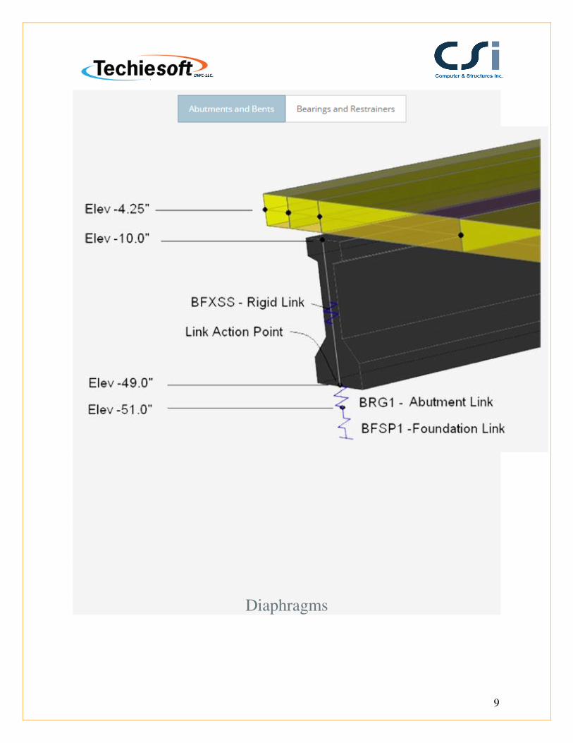
Substructure
Bridge substructures can very accurately be modeled in CSiBridge. Bents, abutments,
restrainers, bearings and foundation springs are all elements that can be defined as either link
or hinge elements.
Page 10
10
Diaphragms may be located at the supports and along the spans. Types include concrete, steel girder, and
detailed steel cross-frames. These may be skewed and staggered. Interior cross frames for steel U-girders
may also be specified.
Post-Tensioning
Page 11
11
Define post-tensioning in CSiBridge using the refined options for laying out tendons and forces. When
defining box girders, CSiBridge will automatically assign the drape locations within the tendon; the
engineer can edit them as well.
Parametric Variations
Page 12
12
CSiBridge allows variations for the entire bridge or just parts of the bridge alignment and slope, for both
horizontal or vertical variations of the deck section. Defining variations parametrically significantly reduces
the amount of time spent on the modeling process.
Page 13
13
Lanes
Quickly define the lanes based on the layout lines of the bridge. The lanes can be defined such that the
width of each lane is wider than the design vehicle. Enveloped response results can be defined later to
accurately model vehicle loads on the bridge.
Structural Components
Page 14
14
Joints
CSiBridge automatically creates joints at structural object intersections or internal joints when meshing
structural objects. Joint coordinates and information may be displayed on screen in the model window or in
tabular format.
Page 15
15
Frames
The frame element uses a general, three-dimensional, beam-column formulation which
includes the effects of biaxial bending, torsion, axial deformation, and biaxial shear
deformations. CSiBridge has a built-in library of standard concrete, steel, and composite
section properties of both US and International Standard sections.
Intermediate joints will automatically be generated where other members intersect with the frame to ensure
finite element connectivity.
Page 16
16
Tendons
In CSiBridge, Tendons are easily drawn as independent objects, with geometry specified as straight lines,
parabolas, circular curves, or other arbitrary shapes. They can also be defined parametrically to drape inside
of a box girder. Tendon loads, including all losses, are easily defined.
Page 17
17
Cables
The cable element is a highly nonlinear element used to model the catenary behavior of slender cables
under their own self-weight. They are particularly useful in modeling suspension bridges or cable-stayed
bridges.
Page 18
18
Shells
The shell element is a type of area object that is used to model membrane, plate, and shell behavior in
planar and three-dimensional structures. The shell material may be homogeneous or layered throughout;
material nonlinearity can also be considered when using the layered shell.
Page 19
19
Solids
The solid element is an eight-node element for modeling three-dimensional structures and solids. It is based
upon an isoparametric formulation that includes nine optional incompatible bending modes and is useful
for modeling objects in which loading, boundary conditions, section properties, or reactions vary by
thickness.
Page 20
20
Links
A link element may exhibit linear, nonlinear, and frequency dependent behavior. The following link
elements are available in CSiBridge: Linear, Multi-linear Elastic, Multi-linear Plastic, Gaps, Hooks,
Dampers, Friction Isolators, Rubber Isolators, T/C Isolators, Frequency-dependent Springs, and Frequency-
dependent Dampers.
Page 21
21
Hinges
Users can create and apply hinge properties to perform pushover analyses in CSiBridge. Nonlinear material
behavior in frame elements (beam/column/brace) can be modeled using fiber hinges. This approach
represents the material in the cross section as discrete points, each following the exact stress-strain curves
of the material. Mixed materials, such as reinforced concrete and complex shapes can be represented.
Page 22
22
Springs
Spring supports are link elements that are used to elastically connect joints to the ground and can be linear
or nonlinear in nature. Nonlinear support conditions can be modeled to include gaps (compression only),
multi-linear elastic or plastic springs, viscous dampers, and base isolators. Advanced modeling capabilities
allow foundations to be included with the superstructure, including piles and spread footings. P-Y multi-
linear force deformation parameters and compression-only soil springs can be defined.
Page 23
23
Loading
Vehicle Loads and Classes
Vehicles are used to define the moving loads in CSiBridge and are most often defined to act on the traffic
lanes. There are standard types of vehicles in the program, or users can design unique vehicles using the
general vehicle specification. Vehicle classes are sets of one or more vehicles that can be assigned to act on
lanes in a moving-load case.
Page 24
24
Load Patterns
A load pattern is a specified spatial distribution of forces, displacements, temperatures, and other effects
that act upon the structure.
Page 25
25
Parametric Loading
Superstructure loads may be defined and assigned to a bridge object model parametrically.
Bridge Object loads may be assigned for any defined load pattern type and may include loads
Page 26
26
due to wearing surfaces, parapets, forms, diaphragms, girders, decks and more. Once the
parametric bridge object loads have been defined they may be easily displayed and modified.
Parametrically defined load assignments are preserved even when changes are made to the bridge object
discretizations, deck types or alignments.
Analysis
Page 27
27
Overview
CSI Solvers have been tried and tested by the industry for over 35 years. The SAPFire Analysis Engine can
support multiple 64-bit solvers for analysis optimization and perform both Eigen Analysis and Ritz
Analysis.
Moving Load
Moving load analysis is available in CSiBridge to compute influence lines and surfaces for traffic lanes on
bridge structures and to analyze these structures for the response due to vehicle live loads. Vehicles can
also be moved in a multi-step analysis. This can use either multi-step static load cases or time-history load
cases, the latter of which can be linear or nonlinear.
Page 28
28
Buckling
Linear (bifurcation) buckling modes of a structure can be found under any set of loads. Buckling can be
calculated from a nonlinear or staged-construction state. Full nonlinear buckling analysis is also available
considering P-delta or large deflections effects. Snap-through buckling behavior can be captured using
static analysis with displacement control. Dynamic analysis can be used for modeling more complex
buckling, such as follower-load problems.
Page 29
29
P-Delta
P-delta analysis captures the softening effect of compression and the stiffening effect of tension. A single
P-delta analysis under gravity and sustained loads can be used to modify the stiffness for linear load cases,
which can later be superposed. Alternatively, each combination of loads can be analyzed for full nonlinear
P-delta effects. P-delta effects are included for all elements and are seamlessly integrated into analysis and
design.
Page 30
30
Pushover
Pushover analysis features in CSiBridge include the implementation of FEMA 356 and the hinge and fiber
hinge option based on stress-strain. The nonlinear layered shell element enables users to consider plastic
behavior of concrete shear walls, slabs, steel plates, and other area finite elements in the pushover analysis.
Force-deformation relations are defined for steel and concrete hinges.
Page 32
32
Dynamic
CSiBridge dynamic analysis capabilities include the calculation of vibration modes using Ritz
or Eigen vectors, response-spectrum analysis, and time-history analysis for both linear and
nonlinear behavior.
Page 33
33
Eigen-vector modal analysis finds the natural vibration modes of the structure, which can be used for
understanding the behavior of the structure, and also as the basis for modal superposition in response-
spectrum and modal time-history load cases. Ritz-vector modal analysis finds the optimum modes for
capturing structural behavior in response-spectrum and modal time-history load cases, and is more
efficient for this purpose than Eigen-vector analysis.
Time Dependent
Staged construction is a type of nonlinear analysis in CSiBridge that allows you to define a
sequence of stages wherein you can add or remove portions of the structure, selectively apply
load to portions of the structure, and to consider time-dependent material behavior such as
aging, creep, and shrinkage.
Page 34
34
Staged construction is variously known as incremental construction, sequential construction, or segmental
construction.
Steady State
Steady state analysis is available to determine the response of the structure due to cyclic
(harmonic, sinusoidal) loading over a range of frequencies. Frequency-dependent stiffness
and damping (complex impedance) properties may be included for modeling foundations and
far-field effects, including radiation damping. Steady state analysis can be used to measure the
effects of multiple machines operating at different frequencies by combining the results of
several analyses in the same model.
Page 35
35
Target Force
During nonlinear static analysis, cable and frame elements can be automatically strained to
achieve specified target axial force values. This is most commonly used to tighten cables to
pre-specified tensions, but it can also be used to jack structures to a specified force using
frame elements.
Load Combinations
CSiBridge allows for an unlimited number of load cases and combinations. Load combination types
include: linear additive, envelope (min/max), absolute add, SRSS, and range combinations. Combination
components can include other combinations.
Page 36
36
Design
Steel Frame
Fully integrated steel frame design includes member size optimization and implementation of design codes.
CSiBridge allows users to interactively view design results at any frame member, change the parameters or
section properties, and display the updated member results.
See supported design codes
Page 37
37
Concrete Frame
Fully integrated concrete frame design in CSiBridge includes: required area of steel calculations, auto
selection lists for new member sizing, implementation of design codes, interactive design and review, and
comprehensive overwrite capabilities.
See supported design codes
Page 38
38
Superstructure
CSiBridge will perform the superstructure design for the following bridge superstructure types and codes:
See supported design codes
Page 39
39
Automated Seismic
Page 40
40
Engineers can define specific seismic design parameters to be applied to the bridge model during an
automated cycle of analysis through design. The new AASHTO seismic design specification has been
incorporated into CSiBridge, including pushover analysis for seismic category D.
Load Rating
Page 41
41
Load Rating Overview
CSiBridge load rating calculates the safe load capacity of a bridge based on the requirements of the
AASHTO Manual for Condition Evaluation and Load and Resistance Factor Rating (LRFR) of Highway
Bridges October 2003 with 2005 Interim Revisions and the Manual for Bridge Evaluation Second Edition
2011 with 2013 Interims.
Page 42
42
Output and Display
Deformed Geometry
Users can display deformed geometry based on any load or combination of loads, as well as animations of
modes.
Page 43
43
Force Diagrams
Shear and moment diagrams display internal shear forces, moments, and displacements at all locations
along the length of a frame element for any load case or load combination. CSiBridge gives the option to
scroll along the length to display values or scroll directly to the maximum value location.
Page 44
44
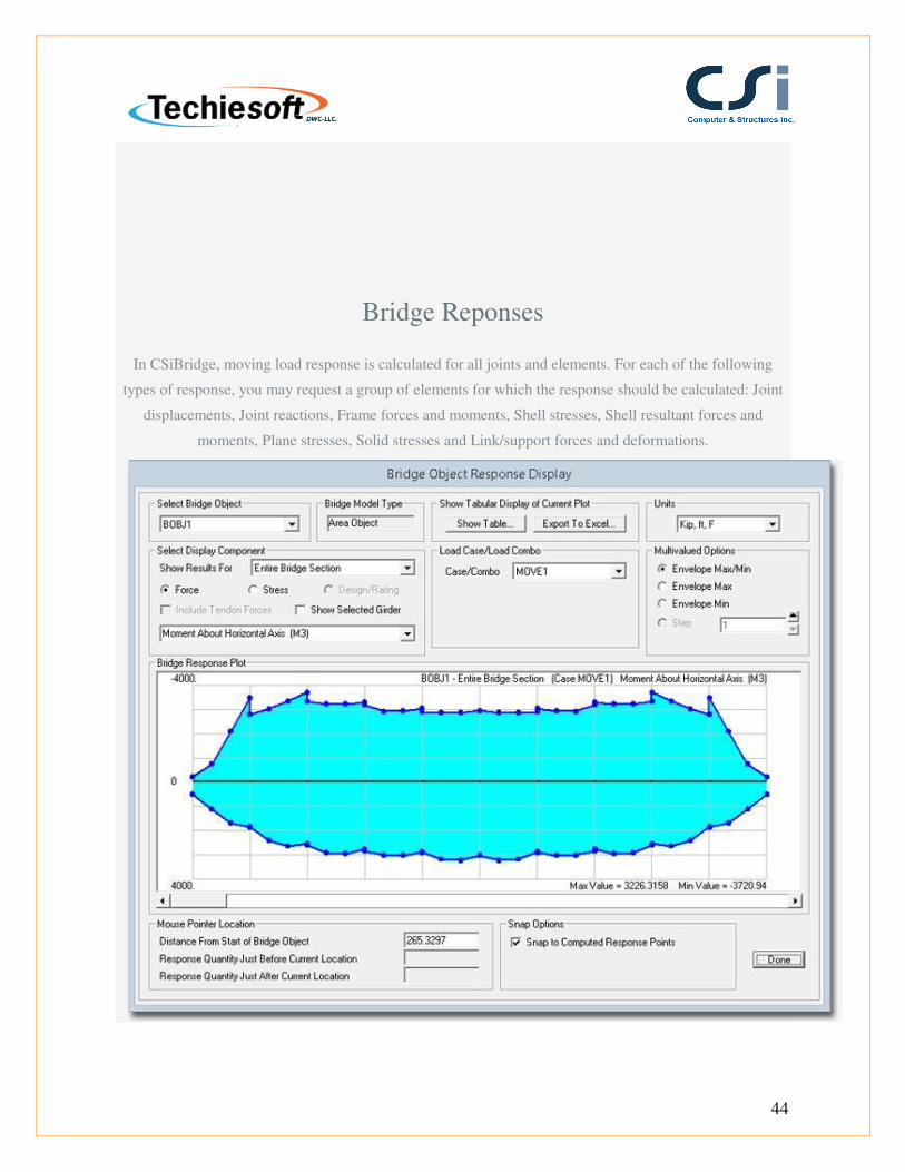
Bridge Reponses
In CSiBridge, moving load response is calculated for all joints and elements. For each of the following
types of response, you may request a group of elements for which the response should be calculated: Joint
displacements, Joint reactions, Frame forces and moments, Shell stresses, Shell resultant forces and
moments, Plane stresses, Solid stresses and Link/support forces and deformations.
Page 45
45
Influence Surfaces
An influence surface can be viewed as a curve of influence values plotted at the load points along a traffic
lane. For a given response quantity (force, displacement, or stress) at a given location in the structure, the
influence value plotted at a load point is the value of that response quantity due to a unit concentrated
downward force acting at that load point.
Page 46
46
Animations
CSiBridge allows users to animate results of vehicles and other loads on the bridge model to
help understand bridge behavior. Create movie files showing time-history and moving vehicle
responses, including multiple vehicles.
Reporting
Report Generation
Pre-formatted printed reports are now available at the push of a button. These reports include all pertinent
model data and the results of analysis and design. Data is presented in tabulated format, along with
graphics, table of contents, and a cover sheet displaying project information and your company name and
logo.
Page 47
47
Tools
Load Optimizer
The load optimizer is a tool in CSiBridge to compute the optimal load application to achieve desired
structural response. Loads may be applied linearly, nonlinearly, or in staged-construction. Goals and limits
may include displacements, forces, moments, and more.
Page 48
48
Section Designer
Section Designer is a utility that is built into CSiBridge. It allows users the ability to create specialized
sections of any arbitrary shape and material, including rebar layout. All section properties, biaxial
interaction diagrams, and moment curvature diagrams are automatically calculated.
Page 49
49
Import and Export
Supported Formats
Page 50
50
CSiBridge supports many industry standards for importing and exporting data. LANDXML, AutoCAD
(DXF/DWG), CIS/2, IFC, and SDNF are all supported. CSiBridge also supports exporting of a model to an
Microsoft Access database. If users are using other analysis packages, CSiBridge can import files from
FrameWorks Plus, IGES, STAAD, and STRUDL.