CSi STANDARD Procedure SOP 647 Revision: CONSOLIDATED SYSTEMS, INC. OPERATING Date: 11/5/2007 Page : 1 of 10 Metal Dek Group ® PROCEDURES Approved by: Allan Abbata Subject: Field Assembly and Installation of Super Versa-Dek 6.5 Roof Deck RECOMMENDED INSTALLATION GUIDELINES 1.0 SCOPE Super Versa-Dek ® 6.5 Roof Deck is an assembly by which an N-Dek ® top panel is mechanically attached to a Versa-Dek ® 3.5 LS bottom panel. This SOP describes the procedures for field assembly and installation of this product. The product is used as part of a roof system. When used as described above, the Super Versa-Dek ® 6.5 LS field assembled panel must be installed so that the ribs of abutting units line up and therefore present a smooth panel/cell transition at the abutted unit ends. 2.0 RESPONSIBILITIES The Metal Dek Group ® is responsible for manufacturing the Super Versa-Dek ® 6.5 Roof Deck according to the required deck layout dimensions and installation directives set by the deck manufacturer’s Engineering Group. The product will be delivered to the jobsite as two (2) components, a Versa-Dek ® 3.5 LS bottom panel and an N-Dek ® top panel. The Super Versa-Dek ® 6.5 Roof Deck profile will be field constructed from these two components to complete the roof deck form assembly by screw attaching the N-Dek ® top panel to the Versa-Dek ® 3.5 LS bottom panel. The Deck Erector will be responsible for installing the Super Versa-Dek ® 6.5 Roof Deck roof panels and associated accessories as shown on the Deck Erection (Final Field Use) Drawings. (See Typical Erection Drawings below in Item No. 6 - Forms and Records). 3.0 REFERENCES 1. SDI Manual of Construction with Steel Deck 2. Steel Deck Institute Design Manual - Latest Publication 3. Metal Dek Group ® Erection (Final Field Use) Drawings 4. Figure 1 - Super Versa-Dek ® 6.5 Roof Deck – Deck Attachment Information 5. Figure 2 - Super Versa-Dek ® 6.5 Roof Deck (Single Span Option) 6. Figure 3 - Super Versa-Dek ® 6.5 Roof Deck (Double Span Option) 7. Figures 4, 5, 6, 7 - Versa-Wedge ™ 3.5 WC Hanger Clip and Load Tables 4.0 REQUIREMENTS The Deck Erector must be experienced in installing this deck type and be thoroughly knowledgeable with the Steel Deck Institute Code of Recommended Standard Practice and Manual of Construction with Steel Deck. All parties involved, including but not limited to, Architect, Engineer of Record, General Contractor, Steel Fabricator, Steel Erector and Roofing Contractor should receive and review documented field assemble and installation procedures for the Super Versa-Dek ® 6.5 Roof Deck. The ultimate review and execution of this procedure will be the responsibility of the General Contractor. 5.0 DEFINITIONS None 6.0 FORMS AND RECORDS Metal Dek Group ® Deck Erection Drawings (Final Field Use Dek Drawings) Figure 1 - Super Versa-Dek ® 6.5 Roof Deck – Deck Attachment Information Figure 2 - Super Versa-Dek ® 6.5 Roof Deck – Single Span Option Figure 3 - Super Versa-Dek ® 6.5 Roof Deck – Multiple Span Option
Transcript
CSi STANDARD Procedure SOP 647
Revision:
CONSOLIDATED SYSTEMS, INC. OPERATING Date:
11/5/2007
Page :
1 of 10
Metal Dek Group® PROCEDURES Approved by: Allan Abbata
Subject: Field Assembly and Installation of Super Versa-Dek 6.5 Roof Deck
RECOMMENDED INSTALLATION GUIDELINES
1.0 SCOPE
Super Versa-Dek® 6.5 Roof Deck is an assembly by which an N-Dek® top panel is mechanically
attached to a Versa-Dek ® 3.5 LS bottom panel. This SOP describes the procedures for field assembly and installation of this product. The product is used as part of a roof system. When used as described
above, the Super Versa-Dek® 6.5 LS field assembled panel must be installed so that the ribs of abutting units line up and therefore present a smooth panel/cell transition at the abutted unit ends.
2.0 RESPONSIBILITIES
The Metal Dek Group® is responsible for manufacturing the Super Versa-Dek® 6.5 Roof Deck according to the required deck layout dimensions and installation directives set by the deck manufacturer’s Engineering Group. The product will be delivered to the jobsite as two (2) components, a
Versa-Dek ® 3.5 LS bottom panel and an N-Dek® top panel. The Super Versa-Dek® 6.5 Roof Deck
profile will be field constructed from these two components to complete the roof deck form assembly by
screw attaching the N-Dek® top panel to the Versa-Dek ® 3.5 LS bottom panel. The Deck Erector will
be responsible for installing the Super Versa-Dek® 6.5 Roof Deck roof panels and associated
accessories as shown on the Deck Erection (Final Field Use) Drawings. (See Typical Erection Drawings below in Item No. 6 - Forms and Records).
3.0 REFERENCES
1. SDI Manual of Construction with Steel Deck 2. Steel Deck Institute Design Manual - Latest Publication
3. Metal Dek Group® Erection (Final Field Use) Drawings
4. Figure 1 - Super Versa-Dek® 6.5 Roof Deck – Deck Attachment Information
The Deck Erector must be experienced in installing this deck type and be thoroughly knowledgeable with the Steel Deck Institute Code of Recommended Standard Practice and Manual of Construction with Steel Deck. All parties involved, including but not limited to, Architect, Engineer of Record, General
Contractor, Steel Fabricator, Steel Erector and Roofing Contractor should receive and review
documented field assemble and installation procedures for the Super Versa-Dek® 6.5 Roof Deck. The ultimate review and execution of this procedure will be the responsibility of the General Contractor.
5.0 DEFINITIONS
None
6.0 FORMS AND RECORDS
Metal Dek Group® Deck Erection Drawings (Final Field Use Dek Drawings)
Figure 1 - Super Versa-Dek® 6.5 Roof Deck – Deck Attachment Information
Figure 2 - Super Versa-Dek® 6.5 Roof Deck – Single Span Option
Metal Dek Group® PROCEDURES Approved by: Allan Abbata
Subject: Field Assembly and Installation of Super Versa-Dek 6.5 Roof Deck
RECOMMENDED INSTALLATION GUIDELINES
7.0 PROCEDURES
(Manufacturers Recommended Installation Guidelines) The following procedures reflect the
recommended field assembly and installation guidelines set forth as standards developed by the deck
manufacturer. The Super Versa-Dek® 6.5 Roof Deck is supplied as a custom 2-part product and shall be assembled and installed with a total understanding of the roofing system, the supplied deck erection
(Final Field Use) drawings and these recommended assembly and installation procedures.
1. Install the Super Versa-Dek® 6.5 Roof Deck in accordance with the Metal Dek Group® Erection Drawings with General Notes and SDI Manual of Construction with Steel Deck. The specific location
and orientation of Super Versa-Dek® 6.5 Roof Deck is depicted on the Metal Dek Group® Erection
Drawings designated as "Final Field Use Dek Drawings".
2. Recommended Procedures for Proper Field Assembly and Installation of Super Versa-Dek® 6.5
Roof Deck:
a.) Installation of the initial Versa-Dek® 3.5 LS bottom panel is critical for maintaining proper bearing and straight alignment of the entire roof deck system. Refer to the Recommended
Installation Procedures and General Notes - Deck Placement on the Final Field Use Dek Drawings.
b.) For proper installation, begin deck panel @ “Start Point” noted on deck drawings. c.) Maintain the proper cover width by stretching the deck to the cover width dimension.
d.) Attach the Versa-Dek® 3.5 LS bottom panel to supporting structural members as shown on the Final Field Use Dek Drawings (Referred to as “Deck1” in the following steps).
e.) Install the N-Dek® top panel to “Deck1” panel per Figure1 with #12 screws @ 6” o.c. starting 1” from each end in deck valleys 2, 3 & 4. This step is critical to insure that the flutes are aligned as shown on the Final Field Use Dek Drawings. Use clamps as required during deck fastening to maintain deck alignment.
f.) Place adjacent Versa-Dek® 3.5 LS bottom panel on supporting members as shown on the Final
Field Use Dek Drawings (Referred to as “Deck2” in the following steps).
g.) The Versa-Dek® 3.5 LS bottom panel side lap connection is achieved by lifting the preceding N-
Dek® top panel (“Deck1”) at the trailing edge (female leg side) to allow the attachment of the starting edge (male leg side) of the next panel. (See Fastening Detail on Final Field Use Dek Drawings). DO NOT INSTALL SIDE LAP FASTENERS AT THIS TIME.
h.) Maintain the proper cover width by stretching the deck to the cover width dimension. Attach “Deck2” panel to supporting members as shown on the Final Field Use Dek Drawings.
i.) Install the N-Dek® top panel to “Deck2” panel per Figure 1 with #12 screws @ 6” o.c. starting 1”
from each end in deck valleys 2, 3 & 4. This is critical to insure that the flutes are aligned as shown on the Final Field Use Dek Drawings. Use clamps as required during deck fastening to maintain deck alignment.
j.) The Super Versa-Dek® 6.5 Roof Deck side lap connection is achieved by attaching the N-Dek®
top panel to the Versa-Dek® 3.5 LS bottom panel at the trailing edge in deck valley 1. (See Fastening Detail on Final Field Use Dek Drawings).
k.) Repeat the above procedures until all roof panels are installed.
l.) Install provided cover plate at the N-Dek® top panel gap at the structural support members as
shown on the Final Field Use Dek Drawings.
3. After the roof deck panels have been installed as shown on the deck erection plans, it will be necessary to make sure all deck ribs and rib openings are lined up with the specified dimensions. It
is the deck manufacturer's recommendation that a gauge block be used to measure the rib gaps to insure proper alignment and appearance.
CSi STANDARD Procedure SOP 647
Revision:
CONSOLIDATED SYSTEMS, INC. OPERATING Date:
11/5/2007
Page :
3 of 10
Metal Dek Group® PROCEDURES Approved by: Allan Abbata
Subject: Field Assembly and Installation of Super Versa-Dek 6.5 Roof Deck
RECOMMENDED INSTALLATION GUIDELINES
4. Subcontractors are to adhere to all OSHA standards for maintaining field construction practices.
Super Versa-Dek® 6.5 Roof Deck components may contain sharp edges and proper field precautions should be implemented.
5. Locations of openings in the Super Versa-Dek® 6.5 Roof Deck shall be the responsibility of the trades requiring them. These openings shall be field cut and reinforced as required by the Engineer of Record. Holes shall be cut prior to installation of the above deck roofing materials. The penetrations shall be cut in such a manner as to present a neat appearance without burrs or sharp edges and in accordance with the SDI Manual of Construction for Steel Decks.
6. Suspended ceilings, light fixtures, duct works and/or other utilities are permitted and can be
suspended from the Super Versa-Dek® 6.5 Roof Deck. The EOR is responsible for the design and
location of all hanging loads from the deck. The Metal Dek Group ® has developed Versa-Wedge
3.5 WC hanger clip systems to suspend point loads up to 100 lbs./hanger. Hangers can be
acquired by calling 803.251.5029. (Phone Number Project Services Group).
7. For any instances in which a situation arises that is not covered by this SOP, contact is to be
established with the Metal Dek Group®, Project Services Department, to provide guidance in
resolving the issue(s) before proceeding.
This SOP is offered as the Metal Dek Group's® recommendation for product installation. It is not
intended as a guarantee or as a requirement. Successful installation can be achieved by following
this procedure. The responsibility for appropriate quality installation procedures and safety
practices ultimately lies with the General Contractor and the subcontractors involved. The Metal
Dek Group® is available to answer questions or concerns associated with this SOP.
CSi STANDARD Procedure SOP 647
Revision:
CONSOLIDATED SYSTEMS, INC. OPERATING Date:
11/5/2007
Page :
4 of 10
Metal Dek Group® PROCEDURES Approved by: Allan Abbata
Subject: Field Assembly and Installation of Super Versa-Dek 6.5 Roof Deck
RECOMMENDED INSTALLATION GUIDELINES
Figure 1: Deck Attachment Information
CSi STANDARD Procedure SOP 647
Revision:
CONSOLIDATED SYSTEMS, INC. OPERATING Date:
11/5/2007
Page :
5 of 10
Metal Dek Group® PROCEDURES Approved by: Allan Abbata
Subject: Field Assembly and Installation of Super Versa-Dek 6.5 Roof Deck
RECOMMENDED INSTALLATION GUIDELINES
Figure 2: Single Span Option
CSi STANDARD Procedure SOP 647
Revision:
CONSOLIDATED SYSTEMS, INC. OPERATING Date:
11/5/2007
Page :
6 of 10
Metal Dek Group® PROCEDURES Approved by: Allan Abbata
Subject: Field Assembly and Installation of Super Versa-Dek 6.5 Roof Deck
RECOMMENDED INSTALLATION GUIDELINES
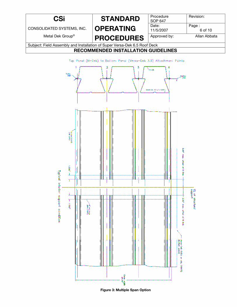
Figure 3: Multiple Span Option
CSi STANDARD Procedure SOP 647
Revision:
CONSOLIDATED SYSTEMS, INC. OPERATING Date:
11/5/2007
Page :
7 of 10
Metal Dek Group® PROCEDURES Approved by: Allan Abbata
Subject: Field Assembly and Installation of Super Versa-Dek 6.5 Roof Deck
RECOMMENDED INSTALLATION GUIDELINES
Figure 4: Versa-Wedge with 1/4”dia. Rod with Roof Slope > 5%
CSi STANDARD Procedure SOP 647
Revision:
CONSOLIDATED SYSTEMS, INC. OPERATING Date:
11/5/2007
Page :
8 of 10
Metal Dek Group® PROCEDURES Approved by: Allan Abbata
Subject: Field Assembly and Installation of Super Versa-Dek 6.5 Roof Deck
RECOMMENDED INSTALLATION GUIDELINES
Figure 5: Versa-Wedge with 3/8”dia. Rod with Roof Slope > 5%
CSi STANDARD Procedure SOP 647
Revision:
CONSOLIDATED SYSTEMS, INC. OPERATING Date:
11/5/2007
Page :
9 of 10
Metal Dek Group® PROCEDURES Approved by: Allan Abbata
Subject: Field Assembly and Installation of Super Versa-Dek 6.5 Roof Deck
RECOMMENDED INSTALLATION GUIDELINES
Figure 6: Versa-Wedge with 1/4”dia. Rod with Roof Slope < 5%
CSi STANDARD Procedure SOP 647
Revision:
CONSOLIDATED SYSTEMS, INC. OPERATING Date:
11/5/2007
Page :
10 of 10
Metal Dek Group® PROCEDURES Approved by: Allan Abbata
Subject: Field Assembly and Installation of Super Versa-Dek 6.5 Roof Deck
RECOMMENDED INSTALLATION GUIDELINES
Figure 7: Versa-Wedge with 3/8”dia. Rod with Roof Slope < 5%