Effectiveness of Direct Bonding of Gas Piping in Mitigating Damage from an Indirect Lightning Flash
Brian Kraft and Robert Torbin
i Executive Summary Damage to gas piping systems during a lightning event may occur due to arcing between the gas piping and some other conductive metallic pathway that is in close proximity. The presence of different levels of electrical potential in these pathways creates the impetus for the arc to occur. The different levels of potential are directly attributable to unequal or non-bonding of the individual pathways to the premise grounding system. A series of physical tests were performed by Lightning Technologies Incorporated for the Titeflex Corporation to simulate a corrugated stainless steel tubing (CSST) gas piping system that has been energized by an indirect lightning flash. This paper summarizes the interpretation of this data and presents recommendations concerning the direct bonding of gas piping systems.1 For testing purposes, a standard residential building was modeled including the bonding (and non-bonding) of the gas piping system after being energized by an indirect lightning flash. The evaluation of the testing data indicates that the risk of damage to the gas piping system due to arcing is significantly reduced when the system is directly bonded to the premise electrical grounding system. A non-bonded piping system would be subject to 97 percent of the charge from an indirect lightning strike, while a direct bonded piping system would be subject to only 20 percent or less of the same charge. Based on the data and the experience of the authors, a set of installation guidelines for the direct bonding of CSST systems was developed. The recommended direct bonding should not be considered a definitive protective measure against all lightning strikes nor construed as an optimum level of bonding.
1.0 Study Objectives
The objective of this reported study was to perform an independent engineering evaluation of data collected during an experimental test program to evaluate the effectiveness of direct bonding of the gas piping system to the grounding system of the premise electrical system used in typical residential construction. The product of this evaluation was the development of installation guidelines for an effective bonding method.
1 The testing results discussed herein are copyrighted by Titeflex Corporation. Reproduction of information covered by Titeflex’s copyright without the express, written consent of Titeflex Corporation is strictly prohibited.
2.1 Piping Systems and Conductive Metallic Pathways A residential gas system is composed of several distinct parts including the gas utility service, the piping system within the building and the pipe and fittings connecting these two parts. The gas utility service is generally comprised of underground polyethylene (PE) piping leading from the distribution network/main in the street to the exterior of the building where the piping is brought above ground via a gas meter riser that connects to the utility gas meter. The meter riser, which provides the transition from underground PE piping to above ground metal piping, is almost always electrically conductive. However, these risers have only a minimum length of steel pipe in direct contact with the earth and are not considered part of the grounding electrode system. Section 250.52 (B) of the NEC prohibits the use of any underground metallic gas piping as a grounding electrode.
In the past, the utility underground gas service piping was commonly all steel pipe, and was often cathodically protected. For this reason, and to prevent inadvertently creating a second electrical ground point, a dielectric union has been traditionally placed by the utility in the gas line prior to the connection point with the gas meter. The dielectric union essentially electrically isolates the underground portion of the gas delivery network from the interior gas piping system. Even though non-conductive polyethylene piping is now used underground in virtually all new construction, the dielectric union continues to be installed for protection from stray currents. The meter riser, regulator and meter are commonly installed outdoors on the side of the building for protection and other practical considerations. Other meter locations were not considered as part of the study, nor were the service connections for LP systems.
House gas piping may consist of rigid steel pipe, copper tubing, corrugated stainless steel tubing or a combination of these three materials. Routing within the building varies greatly depending on the floor plan, gas appliances installed, and installation methods employed by the piping installer. Depending on when the gas piping is installed during the construction schedule and given the limited space available to install utilities, it is not unusual for interferences to occur between different utilities. Therefore, it is not uncommon for gas piping to be routed in close proximity to, or even in direct contact with electrical wiring, heating/cooling ducts, water piping, steel structural supports and appliance exhaust vents. This proximity can have a contributory effect on the impact of lightning strikes to these various metallic pathways.
All gas piping systems (regardless of material) are required by the electrical and fuel gas code to be electrically continuous. All gas piping is installed per the requirements of the locally adopted fuel gas code, most commonly the National Fuel Gas Code (NFPA54), International Fuel Gas Code (IFGC) and the Uniform Plumbing Code (UPC) and, in the case of CSST, in accordance with the manufacturer’s instructions. Gas piping systems must also be bonded to the grounding system in accordance with both Section 250.4(A) (4) and Section 250.104(B) of the NEC. Traditionally, the means for bonding of gas piping has been the equipment grounding conductor when the piping is attached to equipment that is electrically powered. However, the requirement for bonding when the gas equipment is not electrically powered is not clearly stated in the NEC.
Similar to the gas utility service, a residential electrical system consists of the utility electrical service mains, the house wiring within the building and an electrical panel/enclosure that forms the interface between the two. Utility mains are generally run via overhead power lines. However, newer housing developments often employ underground distribution systems. Both overhead and underground systems are locally earth-grounded to provide protection from stray voltage, voltage imposed by lightning, line surges and unintentional contact with higher voltage lines as stated in Section 250.4 (A) (1) of the NEC. The premise electrical panel also incorporates a grounding system, commonly through a grounding electrode conductor and buried electrodes/rods. This provides the electrical ground specific to that building, and is referred to as the house ground.
Other than a three-foot minimum spacing that may be required in some areas, few requirements exist for the location of the gas and electric utility service entrances in relation to each other. It is generally left up to the two utilities to determine the placement of their facilities based on their own requirements and other considerations. While it is most common for the two utility entrances to be located in close proximity, installations resulting in the electrical panel being on the opposite side of the building from the gas meter are not uncommon. The separation distance between the electric panel and/or the grounding electrode system and the gas meter is an important factor in the design of an effective bonding connection.
In the event of an electrical fault, stray voltage or fault current could be imposed onto any conductive metallic pathway within the structure. If there is no effective path to ground, a significant electrical hazard to the occupants of the building would exist. This hazard is largely negated by the bonding of these pathways to the electrical ground system of the building. This bond provides a safe low-impedance path to neutral earth. When the equipment grounding conductor is used as the bonding means, no additional effort is required by the piping installer or the electrical contractor to achieve this condition. Thus, we refer to this as “self-bonding”. In a situation where the gas piping system is not connected to a permanently wired gas appliance, it is unlikely that the system is bonded to the electrical system ground at all based on conventional plumbing/electrical construction practices. An un-bonded metallic system increases the potential for a hazard (to the building occupants) to exist.
2.2 Direct Bonding It is not uncommon for piping systems, including steel gas piping, to be bonded to the electrical ground system through the use of a dedicated wire and clamp. As this method provides a direct connection between the piping system and the electrical ground system, it is referred to as “direct bonding”. For direct bonding, the clamp is attached to a single location on the piping system to provide electrical contact. The wire is then connected to the clamp and routed to either the electrical panel ground or directly to the grounding electrode system.
There are numerous advantages to this method. First, it provides the safety of bonding without reliance on the connection of the gas piping system to a grounded appliance where bonding could be compromised if the appliance is taken out of service, replaced with a differently fueled
unit, or there is a wiring system modification. Additionally, the direct bond method can be visually inspected for continuity, as the clamp and wire connections must be visible. A self-bond connection requires the use of a continuity tester to verify a proper connection at the appliance. Finally, the direct method of bonding provides a low impedance electrical path to ground that is significantly shorter, less electrically resistive, and therefore, more effective than is a self-bond at safely conveying stray voltages and ground-faults to ground.
Direct bonding of all metallic supply lines entering a building is a critical but often overlooked approach when considering protection of a building and its contents during an electrical storm. Lightning strikes near buildings (with ground current transfer distances of up to 1 to 3-km from the strike center) can induce differences in potential between the electrical system and any non-bonded mechanical system. Direct bonding of these systems (using a 6 AWG copper wire) to the building grounding electrode system allows the mechanical systems to be energized at (or near) the same rate as the electrical system and in unison with the voltage wave induced by the lightning strike.
Use of the equipment grounding conductor (EGC) as the bonding means does not achieve the same effect. The EGC (which is typically a 12 or 14 AWG copper wire) does not allow that mechanical system to be energized at the same rate as the electrical system. The path to ground through the EGC is typically much longer (and with greater impedance) than the direct bonding distance (near the service entrance) between each mechanical system and the grounding electrode system. When energized by lightning, this situation permits the electrical potential in the many conductive pathways to become unbalanced, and thus arcing is more likely to occur. Bonding through the equipment grounding conductor is only intended for personnel safety in the event of an electrical fault occurring in the premise wiring system, and has been shown to be inadequate when dealing with lightning energy. That being said, it should be noted that the NEC does not require direct bonding for all metallic systems, nor does it effectively address lightning protection which is considered out-of-scope.
2.3 Lightning Energy
Lightning is, by its very nature, a massively powerful natural phenomenon, capricious and impossible to predict. While significant research has been performed on the lightning phenomenon, general engineering solutions to mitigate its impact have not been widely implemented in the residential market. The occurrence of lightning varies from intense (2 million strikes per year) to light (2,000 strikes per year) on a state-by-state basis. Given that the magnitude, frequency and duration of the energy involved with each lightning strike varies widely, the design of the most effective protection should take local conditions into consideration. Lightning energy is transferred to a structure whether the strike is directly to the building or indirectly through another medium (such as the earth). A direct strike involves both direct hits to the structure or strikes from a branch off of the main bolt. An indirect strike occurs when the energy from the main bolt enters the structure through another pathway such as the overhead power line or through the ground under the house.
Due to the high levels of electrical power inherent in a lightning flash, no single point or path can provide it with an adequate connection to the earth which it seeks. Practically speaking, this means that a direct lightning flash to the ground or to a structure will saturate its immediate path to ground at the object struck. The lightning strike will proceed to conduct its overflow energy indirectly to ground by generating very high voltages and currents in the surrounding earth, objects and structures, commonly to very large distances. In this way, lightning will use all available paths to disperse this electrical energy to neutral earth. In the case of a direct strike to a structure, energy will travel indiscriminately through all of the conductive systems within the building including electrical wiring, communications cables, ventilation ducts, water piping, gas piping, steel structural members and exhaust vents, and often with a destructive effect.
In the case of an indirect flash near to the structure, lightning energy will travel into the structure and through the aforementioned systems if they provide a significant path to neutral earth. The energy level in this situation is such that systems or objects that would not normally be considered electrically continuous and/or conductive can and are used as paths to ground. For example, water in trees or wooden framing members can provide lightning with a path to ground, but with significant damage to the insulating cellulose. Re-bar in unburied footings will respond in the same fashion, with similar explosive damage to the surrounding concrete. The dielectric insulator at the gas service entrance is commonly arced over during a lightning event, with the lighting using the underground riser as a ground point. Any of the conductive systems within the residence that pass near a steel structural support, such as a Lally column in a New England basement, will provide a potential path to ground, even if a short arc through air is required to make the connection.
Under certain circumstances (such as close proximity), CSST can be damaged by arcing to/from other conductors as they are energized by a lightning strike. This arc causes localized heating at the arc termination points, sometimes creating enough heat to melt through the steel pipe wall. This effect is similar to damage caused to aircraft skins by direct lightning flashes. The existing research shows that this type of damage is most closely related to charge delivered, that is, the amount of charge transferred by the arc/flash and the duration over which the arc is active. Charge delivered, or the area under the curve of amperes-versus-seconds, is highly predictive of material damage. Lightning testing commonly utilizes current-versus-time wave shapes identified by values for time-to-peak current amplitude and time-to-current decay of 50-percent peak amplitude (as measured in microseconds) to model both direct and indirect lightning flashes.
3.1 Test Objectives A testing protocol was developed, in consultation with Lightning Technologies Incorporated (LTI), to model an indirect lightning flash striking near the house and the associated energy entering the premise (and the gas piping system) through a pathway provided by the electrical service entrance.2 LTI (Pittsfield, MA) is a leading developer of, and test facility for, lightning protection systems, and was under contract with the Titeflex Corporation to perform these tests. The testing program was designed to evaluate different bonding approaches and techniques for gas piping systems consistent with the requirements of the NEC and the National Fuel Gas Code.
The laboratory testing program was conducted using so-called “typical” lightning profiles, and was only intended to allow relative comparisons of alternative bonding techniques. The results from the testing program provide general guidance on improving the performance of bonding as it affects the ability of the gas piping to absorb lightning energy without damage and to divert this energy safely to ground. However, the recommended bonding technique should not be considered a definitive protective measure against all lightning strikes nor construed as an optimum level of bonding.
3.2 Simulation of Physical Piping System In order to develop a test method to achieve the stated objective, the complex physical system represented by a residential building (including the nearby lightning strike) had to be analyzed and simplified to allow for laboratory simulation. Factors that were considered in the development of the laboratory model and testing procedure included:
• Basic residential wood-framed construction
• Low-pressure metallic gas piping systems and their installation configurations
• Premise electrical wiring systems and their configurations
• Electrically conductive connections between the electrical and gas piping systems
• Lightning, its behavior and typical energy profiles as determined by industry sources
The model used for the evaluation program represented a standard residential building of wood construction with the gas and electrical service entrances of varying distances apart and energized under the following conditions:
• Lighting striking a nearby utility pole and entering through the electrical service mains and saturating the premise electrical grounding system
2 The testing results discussed herein are copyrighted by Titeflex Corporation. Reproduction of information covered by Titeflex’s copyright without the express, written consent of Titeflex Corporation is strictly prohibited.
• Lightning energy traveling through the building via the gas piping and electrical wiring with the gas service entrance as a primary path to neutral earth via a “failed” dielectric fitting
• Polyethylene jacket of the CSST in direct contact with the house wiring
• Polyethylene jacket of the CSST scuffed through normal installation techniques
• Either a non-bonded or direct bonded piping system installed
3.3 Model of Physical System In order to model the physical system comprising a gas piping system installed in a typical single-family residential structure, test samples were setup as shown in Figure 1. A hole was made in the polyethylene jacket (using a standard soldering iron) to represent damage caused to the jacket during installation. This hole was placed over the crown of a corrugation to expose the stainless steel beneath. The electrode was then placed in contact with the PE jacket, entirely covering, but not touching, the exposed stainless steel. If an arc was developed during the test, a new hole was prepared and the electrode moved to this new location before the next test was conducted. New coating holes were spaced approximately one inch apart.
Figure 1: Test Sample Assembly
The generator consisted of a large bank of capacitors connected in parallel, with a resistor/inductor assembly at the capacitor bank output to control output wave shape. The generator was then connected to the sample assembly via a switch. The generator was also connected to the facility ground plane to provide a full circuit. Firing of the generator consisted of applying power to the capacitor bank (switch open) to develop a charge across this bank. When the desired voltage across the bank was reached, the power cycle was discontinued. The switch was then closed, thus subjecting the test sample assembly to the stored charge.
Two current probes and one voltage probe were connected to an oscilloscope to record current output of the generator, current passing into the electrode via an arc to the CSST, and voltage in the CSST. Data time plots allowed the calculation of charge output from the generator and charge traveling down the electrode via an arc from the CSST. Various generator charges were used to explore the relationship between the measured values, arc generation, and the generation of a hole in the CSST for various bonding configurations. Tests were performed for the following direct bond configurations:
• 10 feet of 6 AWG copper wire
• 20 feet of 6 AWG copper wire
• 40 feet of 6 AWG copper wire
• 20 feet of 8 AWG copper wire
• 40 feet of 8 AWG copper wire
Tests were also performed with no direct bond in order to generate some baseline data. A resistor bank, highly resistive relative to the wiring in the sample assembly, was supplied as a direct path to ground for the generator charge in order to model other available, low quality ground paths. This direct path to ground was also necessary for equipment and personnel safety.
3.4 Lightning Profile Due to the chaotic nature of lightning, it is impossible to re-create in an experimental setting. Natural lightning displays an extremely wide range of electrical characteristics for which modern physics is incapable of providing a definitive model. However, simplified models of the electrical impulse from a lightning strike have been developed and can be found in various technical papers and standards. The model chosen for the evaluation of lightning mitigation techniques and materials must be determined by the researcher based on the physical system being studied. The model used for this testing was based on lightning current traveling via the overhead utility wires and internal conductors to the test site (a residential house). This resulted in the selection of an impulse model intended for indirect effects as the most appropriate.
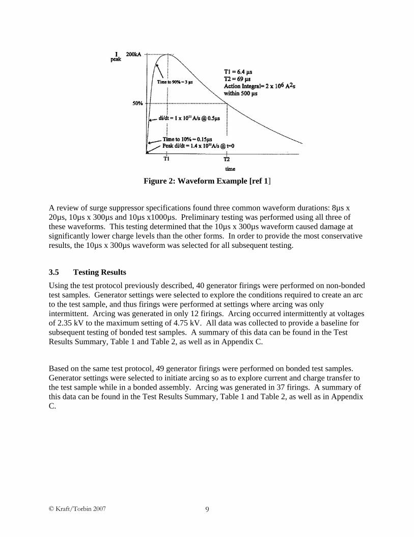
There are commonly used current impulse models for indirect lightning effects found in both the aircraft and surge suppressor industries. An example of one of these waveforms can be seen in Figure 2. Further details and examples of these waveforms can be found in SAE ARP-5412 [ref 1] and various IEEE standards. The majority of these waveforms are similar in shape with the greatest variation found in the magnitude and duration of the lightning energy. These values are expressed in time to rise to peak current and time to fall to 50 percent of peak current.
A review of surge suppressor specifications found three common waveform durations: 8µs x 20µs, 10µs x 300µs and 10µs x1000µs. Preliminary testing was performed using all three of these waveforms. This testing determined that the 10µs x 300µs waveform caused damage at significantly lower charge levels than the other forms. In order to provide the most conservative results, the 10µs x 300µs waveform was selected for all subsequent testing.
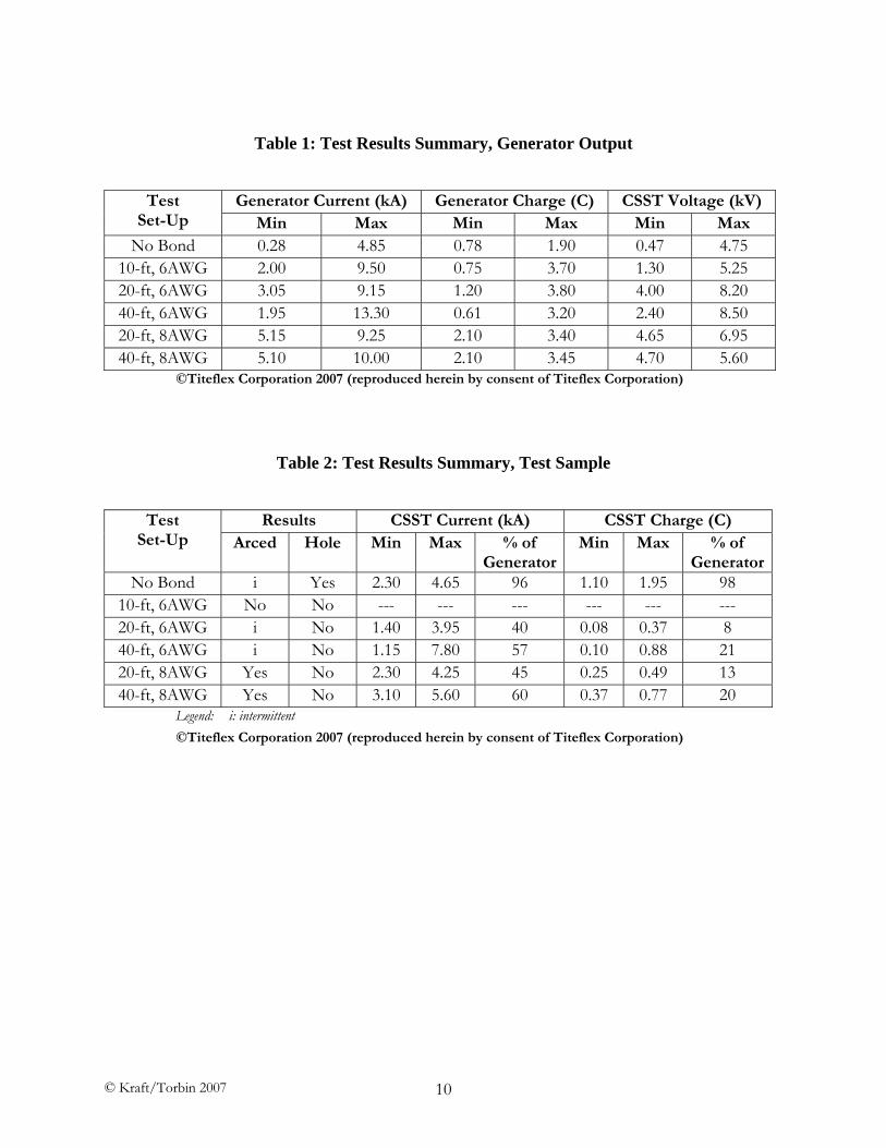
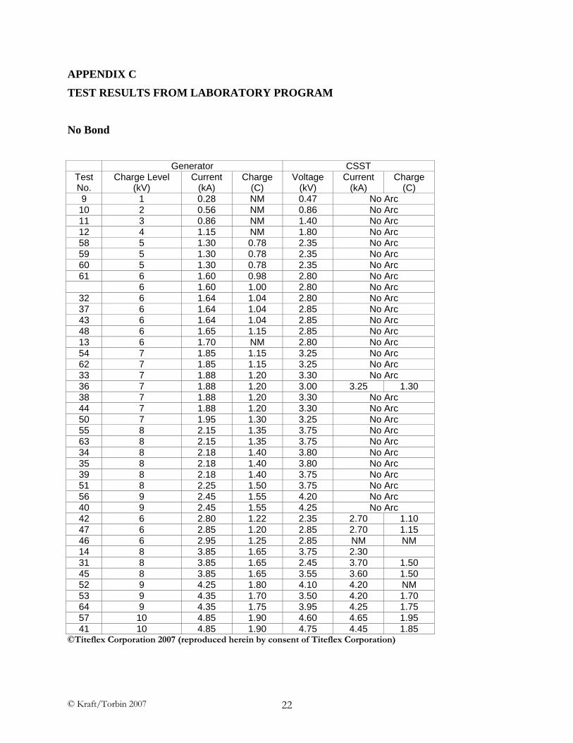
3.5 Testing Results Using the test protocol previously described, 40 generator firings were performed on non-bonded test samples. Generator settings were selected to explore the conditions required to create an arc to the test sample, and thus firings were performed at settings where arcing was only intermittent. Arcing was generated in only 12 firings. Arcing occurred intermittently at voltages of 2.35 kV to the maximum setting of 4.75 kV. All data was collected to provide a baseline for subsequent testing of bonded test samples. A summary of this data can be found in the Test Results Summary, Table 1 and Table 2, as well as in Appendix C.
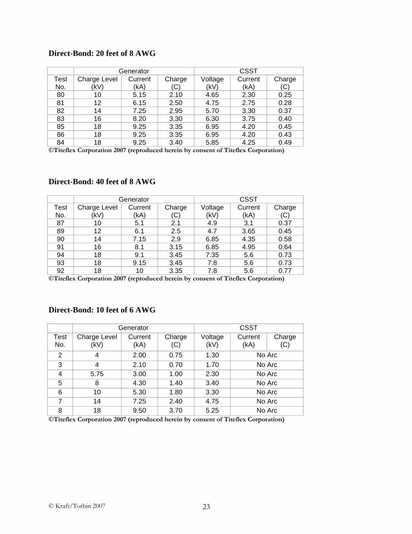
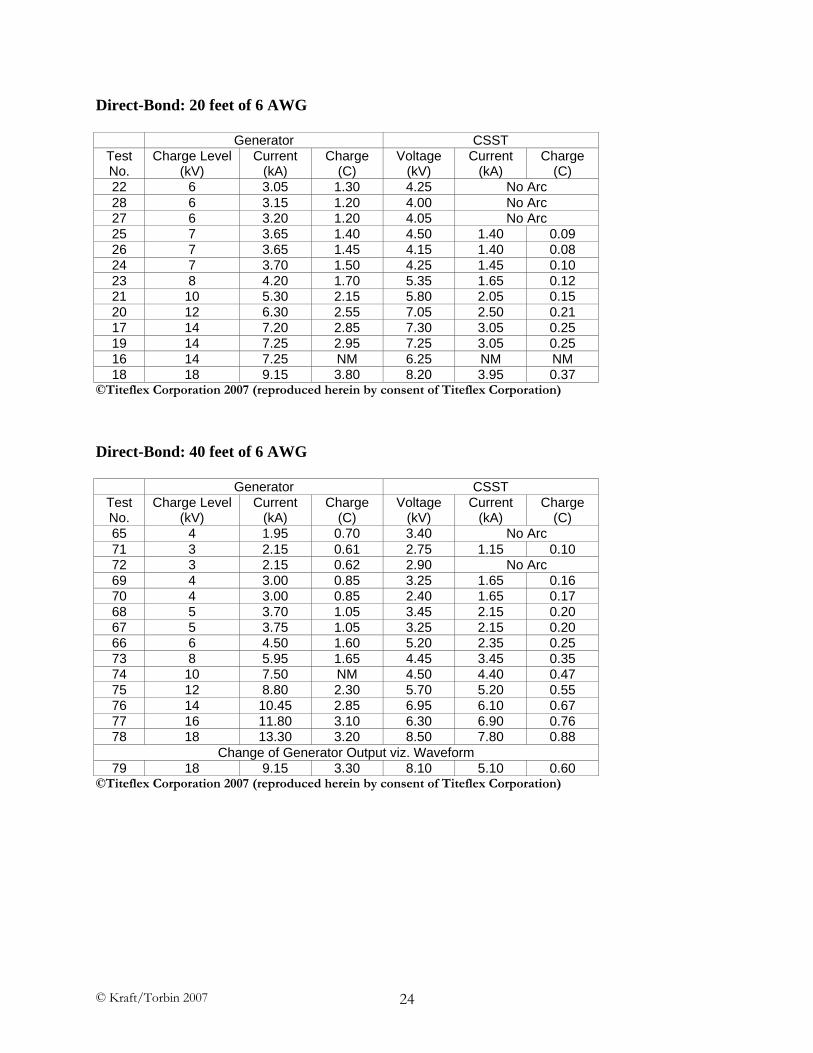
Based on the same test protocol, 49 generator firings were performed on bonded test samples. Generator settings were selected to initiate arcing so as to explore current and charge transfer to the test sample while in a bonded assembly. Arcing was generated in 37 firings. A summary of this data can be found in the Test Results Summary, Table 1 and Table 2, as well as in Appendix C.
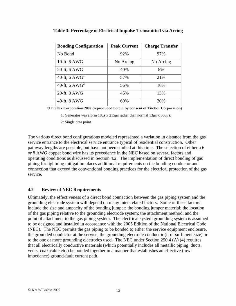
4.1 Interpretation of Results From the test data (see Appendix C) it is clear that the correlation between arc initiation and voltage at the CSST is poor. Arc initiation occurred and did not occur within the range of 2.35kV to 4.75kV. Conversely, the bond configuration of 10-ft of 6 AWG showed no arcing at voltages as high as 5.25kV. As would be expected of a phenomenon as complex as arcing, the data shows that more factors (than were measured during these tests) are significant to arc initiation. Some of these factors may be the size of the hole in the PE jacket, distance from the electrode to the stainless steel of the CSST, time versus voltage, and the condition of the electrode. While further research could be done into these factors, the wide variation in construction techniques would seem to minimize the relevance. The only conclusion that can be reached is that fairly high voltage levels, in the order of thousands of volts, are required to initiate an arc.
It is clear from the non-bonded configuration results that when a poor quality connection to ground is present, an initiated arc to a well grounded conductor will carry the majority of the current and charge. Lightning entering a building through the electrical system decreases the efficacy of the electrical grounding system via charge saturation and travels to neutral earth through the gas service entrance via an arc-over of the dielectric union. The non-bonded configuration was the only configuration examined where the arc generated perforations through the tubing wall.
It is very interesting to note the total lack of arcing with the 10-ft of 6 AWG bond configuration. This bond configuration presented the lowest impedance path to ground of any of the configurations examined in this study. This allowed the discharge to occur in a significantly shorter time period, thus minimizing the exposure of the sample to peak voltages. It can be inferred that insufficient time was available at peak voltage for the intervening dielectric, in this case air, to breakdown and allow an arc to initiate. This effect is of great interest in the prevention of damage to the piping and further studies are recommended.
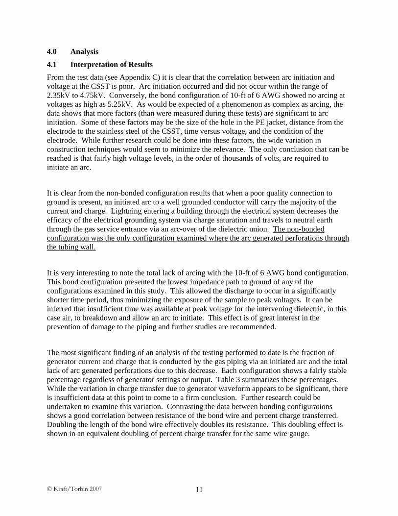
The most significant finding of an analysis of the testing performed to date is the fraction of generator current and charge that is conducted by the gas piping via an initiated arc and the total lack of arc generated perforations due to this decrease. Each configuration shows a fairly stable percentage regardless of generator settings or output. Table 3 summarizes these percentages. While the variation in charge transfer due to generator waveform appears to be significant, there is insufficient data at this point to come to a firm conclusion. Further research could be undertaken to examine this variation. Contrasting the data between bonding configurations shows a good correlation between resistance of the bond wire and percent charge transferred. Doubling the length of the bond wire effectively doubles its resistance. This doubling effect is shown in an equivalent doubling of percent charge transfer for the same wire gauge.
1: Generator waveform 18μs x 215μs rather than normal 13μs x 300μs.
2: Single data point.
The various direct bond configurations modeled represented a variation in distance from the gas service entrance to the electrical service entrance typical of residential construction. Other pathway lengths are possible, but have not been studied at this time. The selection of either a 6 or 8 AWG copper bond wire has its precedence in the NEC based on several factors and operating conditions as discussed in Section 4.2. The implementation of direct bonding of gas piping for lightning mitigation places additional requirements on the bonding conductor and connection that exceed the conventional bonding practices for the electrical protection of the gas service.
4.2 Review of NEC Requirements Ultimately, the effectiveness of a direct bond connection between the gas piping system and the grounding electrode system will depend on many inter-related factors. Some of these factors include the size and ampacity of the bonding jumper; the bonding jumper material; the location of the gas piping relative to the grounding electrode system; the attachment method; and the point of attachment to the gas piping system. The electrical system grounding system is assumed to be designed and installed in accordance with the 2005 Edition of the National Electrical Code (NEC). The NEC permits the gas piping to be bonded to either the service equipment enclosure, the grounded conductor at the service, the grounding electrode conductor (if of sufficient size) or to the one or more grounding electrodes used. The NEC under Section 250.4 (A) (4) requires that all electrically conductive materials (which potentially includes all metallic piping, ducts, vents, coax cable etc.) be bonded together in a manner that establishes an effective (low-impedance) ground-fault current path.
The National Electrical Code contains many references to the requirements for bonding of electrically conductive materials which include wiring, piping, ducts, vents and structural steel. These requirements are specified throughout Section 250 of the NEC and all have the common goal of protecting the public safety from electrical faults within the premise wiring system by establishing an effective ground-fault current path. The objectives of this study were focused on establishing more effective bonding of gas piping systems that may become energized by indirect lightning strikes near the building. Towards that end, the authors conducted a study of the NEC to review its coverage for the use and type of bonding for other conductive materials and pathways to ground, and to compare those requirements with the conventional bonding practices used for gas piping. Appendix B contains a listing of references within the NEC for use of direct bonding and the application of a 6 AWG copper wire as the bonding means. It is quite clear that the use of a 6 AWG copper bond wire is a well established approach for other, similar conductive metallic systems; that a 6 AWG copper wire will be an effective means for diverting (to ground) much of the energy associated with an indirect lightning strike; and the use of direct bonding should be a familiar and straightforward solution to implement in the field by electrical contractors.
4.3 Installation Instructions for Direct Bonding Based, in part, on the testing results and subsequent analysis, and the general practice of bonding established through the NEC, a separate set of installation instructions has been developed for direct bonding of gas piping systems. These generic instructions have been included as Appendix A. In essence, the instructions require the installation of a 6 AWG copper wire from a single attachment point on the gas piping system near the service entrance of the building directly to the grounding electrode system. All of the recommended practices and sizing criteria are consistent with the requirements of Section 250 of the NEC and the National Fuel Gas Code. When approved by each CSST manufacturer, these bonding practices will become part of their published installation instructions, and a mandatory requirement for all new installations. In accordance with NEC Section 110.3(B), listed equipment shall be installed and used in accordance with the manufacturer’s instructions and the terms of the listing. In some jurisdictions, the manufacturer’s instructions are permitted to take precedent over the affected code when they are more conservative or restrictive in practice.
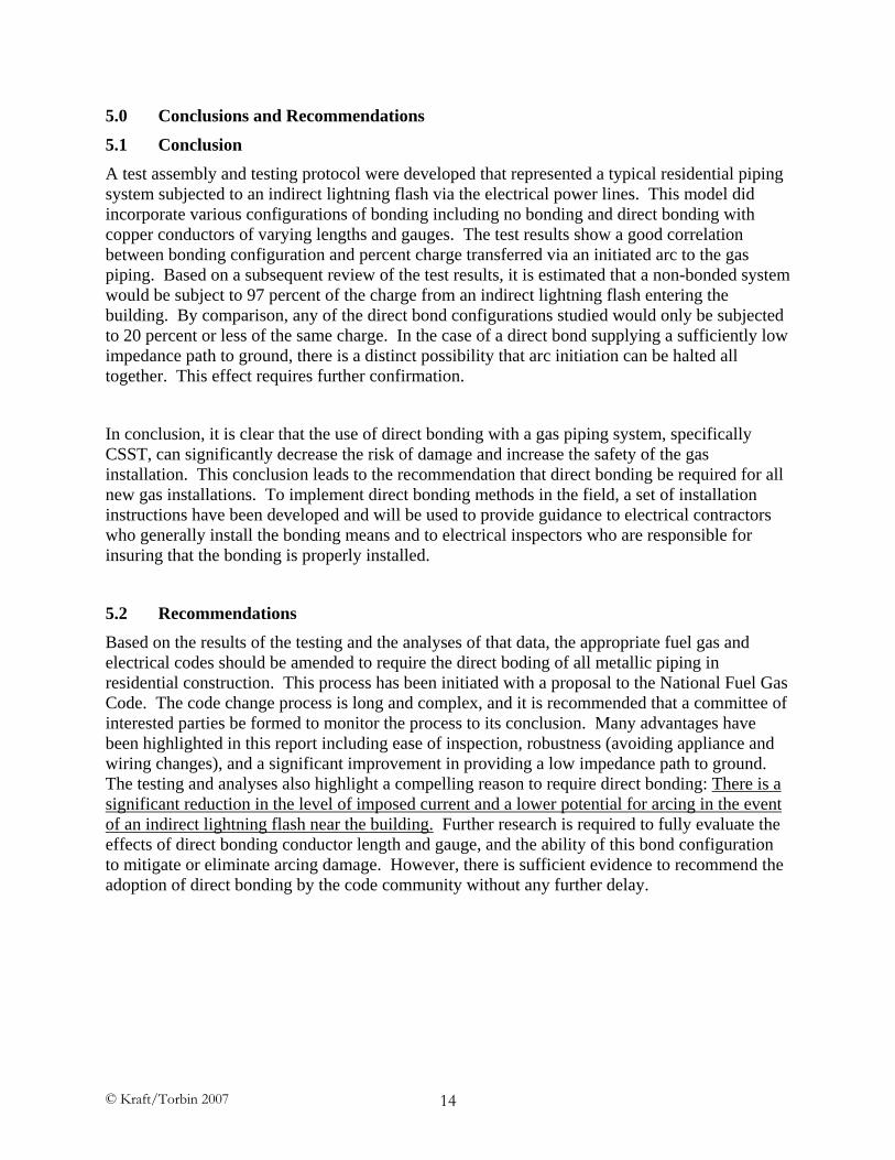
5.1 Conclusion A test assembly and testing protocol were developed that represented a typical residential piping system subjected to an indirect lightning flash via the electrical power lines. This model did incorporate various configurations of bonding including no bonding and direct bonding with copper conductors of varying lengths and gauges. The test results show a good correlation between bonding configuration and percent charge transferred via an initiated arc to the gas piping. Based on a subsequent review of the test results, it is estimated that a non-bonded system would be subject to 97 percent of the charge from an indirect lightning flash entering the building. By comparison, any of the direct bond configurations studied would only be subjected to 20 percent or less of the same charge. In the case of a direct bond supplying a sufficiently low impedance path to ground, there is a distinct possibility that arc initiation can be halted all together. This effect requires further confirmation.
In conclusion, it is clear that the use of direct bonding with a gas piping system, specifically CSST, can significantly decrease the risk of damage and increase the safety of the gas installation. This conclusion leads to the recommendation that direct bonding be required for all new gas installations. To implement direct bonding methods in the field, a set of installation instructions have been developed and will be used to provide guidance to electrical contractors who generally install the bonding means and to electrical inspectors who are responsible for insuring that the bonding is properly installed.
5.2 Recommendations Based on the results of the testing and the analyses of that data, the appropriate fuel gas and electrical codes should be amended to require the direct boding of all metallic piping in residential construction. This process has been initiated with a proposal to the National Fuel Gas Code. The code change process is long and complex, and it is recommended that a committee of interested parties be formed to monitor the process to its conclusion. Many advantages have been highlighted in this report including ease of inspection, robustness (avoiding appliance and wiring changes), and a significant improvement in providing a low impedance path to ground. The testing and analyses also highlight a compelling reason to require direct bonding: There is a significant reduction in the level of imposed current and a lower potential for arcing in the event of an indirect lightning flash near the building. Further research is required to fully evaluate the effects of direct bonding conductor length and gauge, and the ability of this bond configuration to mitigate or eliminate arcing damage. However, there is sufficient evidence to recommend the adoption of direct bonding by the code community without any further delay.
1. ----. ARP5412, Aircraft Lightning Environment and Related Test Waveforms, Warrendale, PA: SAE, 2005.
2. ----. NFPA 54, National Fuel Gas Code, National Fire Protection Association, Quincy, MA 1999, 2002, 2006.
3. ----. NFPA 70, National Electrical Code, National Fire Protection Association, Quincy, MA 1999, 2005.
4. ----. NFPA 780, Standard for the Installation of Lightning Protection Systems, National Fire Protection Association, Quincy, MA 2000, 2004.
5. Anderson, R.B. and Eriksson, A.J., Lightning Parameters for Engineering Applications, Suceava, Roumania: Colloquium and Study Committee Meeting, Cigre Study Committee 33, 1979.
6. Cianos, N. and Pierce, E.T., A Ground-Lightning Environment for Engineering Usage, Menlo Park, California: Stanford Research Institute, 1972. Figure 25, pp. 66.
7. Crouch, K.E., Lightning Technologies Incorporated, Pittsfield, MA 2007.
8. Kithil, R., Lightning Protection for Engineers, Louisville, CO: National Lightning Safety Institute, 2005.
9. Martzloff, F. D. and Crouch, K. E., “Coordination de la Protection Contre les Surtensions dans les Reseaux Basse Tension Residentiels”, Proceedings 1978 IEEE Canadian Conference on Communications and Power, 78CH1373-0, pp. 451-454.
10. Rupke, E., Lightning Technologies Incorporated, Pittsfield, MA 2004-2007.
GUIDELINES FOR DIRECT (ELECTRICAL) BONDING OF CSST SYSTEMS This guideline document describes the requirements for the direct bonding of corrugated stainless steel tubing (CSST) gas piping systems. The bonding of CSST shall be installed by a licensed contractor recognized by the local jurisdiction as capable of performing such work.
Direct bonding is required for all CSST natural and LP gas piping systems whether or not the connected gas equipment is electrically powered. These guidelines are applicable to all new CSST installations as well as partial retrofits of CSST to existing steel pipe and copper tubing systems. These guidelines are applicable for typical single-family and multi-family dwellings and certain commercial buildings. An engineer knowledgeable in electrical system design and the local electrical code should review the bonding requirements for each commercial application to determine if additional bonding and/or larger conductor sizes are required.
CSST installed inside or attached to the exterior of a building or structure shall be electrically continuous and directly bonded to an effective ground-fault current path. The gas piping system shall be considered to be directly bonded when installed in accordance with the following:
• A bonding jumper is permanently and directly connected to the electrical service grounding system. This shall be achieved through a connection to the electrical service equipment enclosure, the grounded conductor at the electrical service, the grounding electrode conductor (where of sufficient size) or to the one or more grounding electrodes used. (NEC Section 250.104 B)
• A single bond connection shall be made to the building gas piping downstream of the utility meter, but near the service entrance (either outdoors or indoors) of the structure, or downstream of the gas meter of each individual housing unit within a multi-family structure. A “daisy chain” configuration of the bonding conductor shall be permitted for multi-meter installations. A bonding connection shall not be made to the underground, natural gas utility service line.
• The bonding conductor shall not be smaller than a 6 AWG copper wire. The bonding conductor shall be installed and protected in accordance with the NEC Section 250.64.
• The bonding conductor shall be attached in an approved manner in accordance with NEC Article 250.70 and the point of attachment for the bonding conductor shall be accessible.
• Bonding/grounding clamps shall be listed to UL 467 or other acceptable national standards.
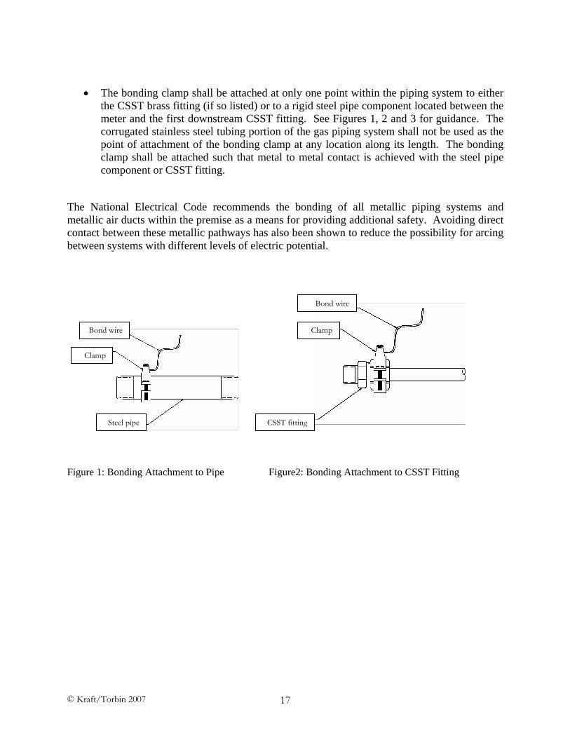
• The bonding clamp shall be attached at only one point within the piping system to either the CSST brass fitting (if so listed) or to a rigid steel pipe component located between the meter and the first downstream CSST fitting. See Figures 1, 2 and 3 for guidance. The corrugated stainless steel tubing portion of the gas piping system shall not be used as the point of attachment of the bonding clamp at any location along its length. The bonding clamp shall be attached such that metal to metal contact is achieved with the steel pipe component or CSST fitting.
The National Electrical Code recommends the bonding of all metallic piping systems and metallic air ducts within the premise as a means for providing additional safety. Avoiding direct contact between these metallic pathways has also been shown to reduce the possibility for arcing between systems with different levels of electric potential.
Figure 1: Bonding Attachment to Pipe Figure2: Bonding Attachment to CSST Fitting
NEC REFERENCES FOR THE USE OF 6 AWG COPPER BOND JUMPER
NFPA 70-2005 Edition of the National Electrical Code
250.53: Grounding Electrode System Installation. (C) Bonding Jumper. The bonding jumper(s) used to connect the grounding electrodes together to form the grounding electrode system shall be installed in accordance with 250.64(A), (B), and (E) shall be sized in accordance with 250.66, and shall be connected in the manner specified in 250.70.
250.66: Size of Alternating-Current Grounding Electrode Conductor. The size of the grounding electrode conductor of a grounded or ungrounded ac system shall not be less than given in Table 250.66, except as permitted in 250.66(A) through (C).
(A) Connections to Rod, Pipe, or Plate Electrodes. Where the grounding electrode conductor is connected to rod, pipe, or plate electrodes as permitted in 250.52(A)(5) or (A)(6), that portion of the conductor that is the sole connection to the grounding electrode shall not be required to be larger than 6 AWG copper wire or 4 AWG aluminum wire.
Table 250.66: Grounding Electrode Conductor for A-C Systems: Size of Service Entrance Conductor:
2 or smaller => 8 AWG Copper
1 or 1/0 => 6 AWG Copper
2/0 or 3/0 => 4 AWG Copper
250.64: Grounding Electrode Conductor Installation. Grounding Electrode Conductors shall be installed as specified in 250.64(A) through (F).
250.64(B): Securing and Protection Against Physical Damage. When exposed, a grounding electrode conductor or its enclosure shall be securely fastened to the surface on which it is carried. A 4 AWG or larger copper or aluminum grounding electrode conductor shall be protected where exposed to physical damage. A 6 AWG grounding electrode conductor that is free from exposure to physical damage shall be permitted to be run along the surface of the building construction without metal covering or protection where it is securely fastened to the construction; otherwise it shall be in rigid metal conduit, intermediate metal conduit, rigid nonmetallic conduit, electrical metallic tubing, or cable armor. Grounding electrode conductors smaller than 6 AWG shall be in rigid metal conduit, intermediate metal conduit, rigid nonmetallic conduit, electrical metallic tubing, or cable armor.
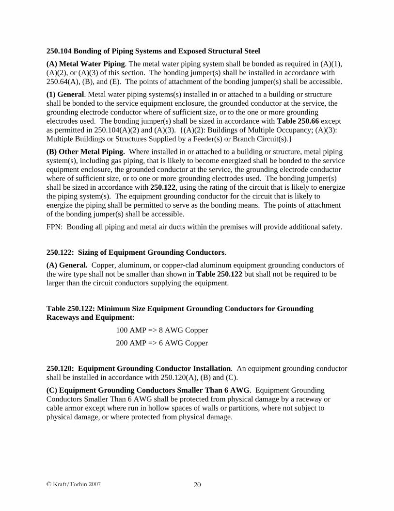
250.104 Bonding of Piping Systems and Exposed Structural Steel (A) Metal Water Piping. The metal water piping system shall be bonded as required in (A)(1), (A)(2), or (A)(3) of this section. The bonding jumper(s) shall be installed in accordance with 250.64(A), (B), and (E). The points of attachment of the bonding jumper(s) shall be accessible.
(1) General. Metal water piping systems(s) installed in or attached to a building or structure shall be bonded to the service equipment enclosure, the grounded conductor at the service, the grounding electrode conductor where of sufficient size, or to the one or more grounding electrodes used. The bonding jumper(s) shall be sized in accordance with Table 250.66 except as permitted in 250.104(A)(2) and (A)(3). {(A)(2): Buildings of Multiple Occupancy; (A)(3): Multiple Buildings or Structures Supplied by a Feeder(s) or Branch Circuit(s).}
(B) Other Metal Piping. Where installed in or attached to a building or structure, metal piping system(s), including gas piping, that is likely to become energized shall be bonded to the service equipment enclosure, the grounded conductor at the service, the grounding electrode conductor where of sufficient size, or to one or more grounding electrodes used. The bonding jumper(s) shall be sized in accordance with 250.122, using the rating of the circuit that is likely to energize the piping system(s). The equipment grounding conductor for the circuit that is likely to energize the piping shall be permitted to serve as the bonding means. The points of attachment of the bonding jumper(s) shall be accessible.
FPN: Bonding all piping and metal air ducts within the premises will provide additional safety.
250.122: Sizing of Equipment Grounding Conductors.
(A) General. Copper, aluminum, or copper-clad aluminum equipment grounding conductors of the wire type shall not be smaller than shown in Table 250.122 but shall not be required to be larger than the circuit conductors supplying the equipment.
Table 250.122: Minimum Size Equipment Grounding Conductors for Grounding Raceways and Equipment:
100 AMP => 8 AWG Copper
200 AMP => 6 AWG Copper
250.120: Equipment Grounding Conductor Installation. An equipment grounding conductor shall be installed in accordance with 250.120(A), (B) and (C).
(C) Equipment Grounding Conductors Smaller Than 6 AWG. Equipment Grounding Conductors Smaller Than 6 AWG shall be protected from physical damage by a raceway or cable armor except where run in hollow spaces of walls or partitions, where not subject to physical damage, or where protected from physical damage.
800.100: Cable and Primary Protector Grounding (Communications) (D) Bonding Electrodes. A bonding jumper not smaller than 6 AWG copper or equivalent shall be connected between the communications grounding electrode and power grounding electrode system at the building or structure served where separate electrodes are used.
810.21: Grounding Conductors – Receiving Stations (Radio and Television Equipment) (J) Bonding of Electrodes. A bonding jumper not smaller than 6 AWG copper or equivalent shall be connected between the radio and television equipment grounding electrode and power grounding electrode system at the building or structure served where separate electrodes are used.
820.100: Cable Grounding (Community Antenna Television and Radio Distribution Systems) (D) Bonding of Electrodes. A bonding jumper not smaller than 6 AWG copper or equivalent shall be connected between the community antenna television system’s grounding electrode and power grounding electrode system at the building or structure served where separate electrodes are used.
830.100: Cable, Network Interface Unit, and Primary Protector Grounding (Network-Powered Broadband Communications Systems) (D) Bonding of Electrodes. A bonding jumper not smaller than 6 AWG copper or equivalent shall be connected between the network-powered broadband communications system grounding electrode and power grounding electrode system at the building or structure served where separate electrodes are used.
NFPA 780-2004 Standard for the Installation of Lightning Protection Systems
4.19.2.2: Conductors used for the bonding of grounded metal bodies or isolated metal bodies requiring connection to the lightning protection system shall be sized in accordance with bonding conductor requirements in Table 4.1.1.1 (A) and Table 4.1.1.1 (B).
4.1.1.1 (A): Ordinary structures not exceeding 23-m (75ft) in height shall be protected with Class I materials as shown in Table 4.1.1.1 (A).
Table 4.1.1.1 (A) Minimum Class I Material Requirements: Bonding Conductor, cable (solid or stranded): Cross section area = 26,240 cir mils.
NOTE: 6 AWG wire has a cross sectional area of 26,251 cir mils.