Siemens reserves the right to change its products and services at any time.
In addition, manuals are subject to change without notice. The hardcopy documents corre-spond to the version at the time of system delivery and/or printout. Versions to hardcopydocumentation are not automatically distributed. Please contact your local Siemens officeto order current version or refer to our website http://www.healthcare.siemens.com.
DisclaimerSiemens provides this documentation “as is“ without the assumption of any liability underany theory of law.
The installation and service of equipment described herein requires superior understand-ing of our equipment and may only be performed by qualified personnel who are speciallytrained for such installation and/or service.
Only qualified and system-trained service staff are allowed to perform CT system installa-tion, service, maintenance, and quality assurance. Ensure that the most recent version ofthe technical documentation is available.
To avoid any risk of injury to persons and/or damage to the system, read and observe theGeneral Safety Notes (TD00-000.860.01.xx.xx). Please read and observe the Prod-uct-specific Safety Notes (C2-028.860.01.xx.xx) which include very importantsafety-related information as well as information about the handling of screws and nuts,application of Loctite, and instructions for torque wrenches. You will find the following infor-mation in the “Product-specific Safety Notes.”
• Safety information related to the method of risk management .
• General safety information such as handling of technical documentation, CT systemtraining request, radiation protection, electrical protection, service tools.
• General safety information about working in the gantry with the power off/on .
• Use of the patient table as lifting device for gantry part replacement .
• Laser products .
• Attachment of screws and nuts, application of Loctite, adjustment instructions for thetorque wrench.
PHS-specific warnings 0
WARNING [ hz_serdoc_F13G01U11M01 ]
Use of the service-enable switch (table) disables collisionprotection.
Information for switching off the gantry power 1.2
1. Switch system toCOMP/ON at the control box.
2. Switch OFF the gantry/PHS power using service push-button S1 in the PDC.
Secure the circuit breakers that S1 switched OFF against unintended switch-on(e.g. lock and tag).
NOTE Read and observe the safety information in the “Product-spe-cific safety notes” prior to performing service work on thepatient table. If the patient table power is switched off for ser-vice work, always secure it against accidental switch-on.
• PDC-A: F7 is tripped using S1. To apply power to the PHS for service movement, resetF7 and wait two minutes for the table firmware to initialize.
Fig. 6: F7 in PDC-APos. 1 F7
Relay K7 uses normally closed contacts. When the system is powered OFF in thenormal way, the firmware energizes K7 to remove power. Only when S1 is used
will the relay de-energize to allow power from F7 to flow to the table for testing.
NOTE With software versions VA40 and higher, the PHS controlsrun on the UMAS.
Therefore, the UMAS has to be switched on with breaker F11in addition to F7.
Fig. 7: Example of a PHS 3 service movement panel Pos. 1 power indicator
Pos. 2 standby indicator
Pos. 3 service on
Pos. 4 service unlock
• Ensure that the power indicator (LED) is ON (Item 1) and standby status hasbeen reached (LED ON at Item 2). This may take 2 minutes after power isswitched on.
• Push the service switch (item 3) to activate service mode.
LED will illuminate.
• Push and hold the unlock button (Item 4) and at the same time use the move-ment switches.
Service movement only works if all 4 foot switches are still connected orthe foot switch cables (X741a/b and X751a/b) are plugged into the serviceplugs.
In case of a malfunction of the vertical drive, manual vertical movement of the tabletop isstill possible via a mechanical interface at the vertical drive motor.
PHS-1B 0
Crank for manual vertical movement
The emergency crank for vertical movement is attached to the bottom cover in the back.
Fig. 8: Crank for vertical movement Pos. 1 Crank
• Observe the vertical move directions according to the label as shown.
• Attach a hex nut to the drive axle (item 1) and move the tabletop mechanicallyby turning a wrench in clockwise direction (for raising) or counterclockwisedirection (for lowering).
Normally, a standard tool set is required for performing service as described in this docu-ment. If special tools are needed, they are described in the relevant replacement descrip-tion under the “Tools” item.
NOTE Torque wrenches must be checked for accuracy on a regularbasis.
This chapter describes the removal and replacement of the PHS covers.
Fig. 18: Table covers, overview
Covers described in this document.
• Tabletop covers (front and rear). (Not shown) These are the covers below the table-
top plate covering the support. They are removed to gain access to the drive motors,tabletop belt, horizontal sensors, and horizontal controllers.
• Telescopic covers. (Item 1) These are released from the tabletop support and left atthe lowest position for most service operations, but are removed to gain access to thevertical drive components.
• Tabletop lower rear cover. (Item 2) This cover is underneath the support at the back ofthe table. It is removed to gain access to the support belt and for greater access to thesupport components.
• Front and back end covers. (Item 3) These are at each end of the side covers.
• Switchplate cover. (Item 4) These are at each end of the side covers.
• Side support (left/right). (Item 5) These are the aluminum covers on each side of thetabletop. They are normally only removed and replaced if damaged.
• Table electronics cover. (Item 6) This is removed to gain access to the components inthe electronics tray.
3. Switch OFF the gantry/PHS power using service push-button S1 in the PDC.
Secure the circuit breakers that S1 switched OFF against unintended switch-on(e.g. lock and tag).
NOTE Read and observe the safety information in the “Prod-uct-specific safety notes” prior to performing service work on the patient table. If the patient table power is switched offfor service work, always secure it against accidentalswitch-on.
4. Push table in to the end stop.
5. Remove the switchplate cover (Front and rear end covers / switchplate cover / p. 40).
Prerequisites 0
Safety
WARNING [ hz_serdoc_F13G01U12M03 ]
Avoid accident and injury or damage to parts.
Risk of accident and injury!
Read and observe the safety information contained inthe “General” section of this document and/or the
- The front cover has another cover plate attached at the front.
- Remove the front-end covers (Front and rear end covers / switchplate cover / p. 40) and the cover plate securing screws (item 1) from underneath the tabletop plate, andslide the cover plate out in a forward motion.
NOTE Beginning with delivery in June 2009, the cover plate is fixedwith 5 screws instead of 3.
- Remove the 6 securing screws (similar to back top cover) and slide the top cover outtoward the back while unplugging the ground connector.
Installation 0
1. Replace the covers and ground connectors and install the screws.
Startup 0
Electrical
1. Switch on circuit breakers F2, F3, F5, F6, F7, and F11 in the PDC A and F2 in the PDCB (not for Definition AS).
First switch the F2, F3, F5, F6 circuit breakers to the “0” position and then to the“1” position.
2. Switch the system to the SYSTEM/ON status at the control box.
Read and observe the safety information contained in
the “General” section of this document and/or the“Product specific safety notes”.
Time and Manpower
• 1 person
• Estimated total repair time: 15 min.
Tools and auxiliary equipment
•
Standard service kit
Preliminary steps 0
1. Raise the patient table to height of 125.
2. Switch system toCOMP/ON at the control box.
3. Switch OFF the gantry/PHS power using service push-button S1 in the PDC.
Secure the circuit breakers that S1 switched OFF against unintended switch-on(e.g. lock and tag).
NOTE Read and observe the safety information in the “Prod-uct-specific safety notes” prior to performing service work on the patient table. If the patient table power is switched offfor service work, always secure it against accidentalswitch-on.
- Side support (left/right), material number 86 14 542
Prerequisites 0
Safety
WARNING [ hz_serdoc_F13G01U12M03 ]
Avoid accident and injury or damage to parts.
Risk of accident and injury!
Read and observe the safety information contained in
the “General” section of this document and/or the“Product specific safety notes”.
Time and Manpower
• 1 person
• Estimated total repair time: 45 min.
Tools and auxiliary equipment
•
Standard service kit
Preliminary steps 0
1. Raise the patient table to height of 125.
2. Switch system to COMP/ON at the control box.
3. Switch OFF the gantry/PHS power using service push-button S1 in the PDC.
Secure the circuit breakers that S1 switched OFF against unintended switch-on(e.g. lock and tag).
NOTE Read and observe the safety information in the “Prod-uct-specific safety notes” prior to performing service work on the patient table. If the patient table power is switched offfor service work, always secure it against accidentalswitch-on.
4. Remove the front and back end covers and back switchplate (Front and rear end cov-ers / switchplate cover / p. 40)
Fig. 25: Side cover securing screws • From inside the frame, remove the 6 screws (e.g. Item 1) securing the
side cover. The tabletop will have to be moved in and out to gainaccess to all screws.
• Start with the front screws followed by the back screws, leaving thecenter screws until last.
• After pushing the tabletop plate fully inward to its limit, hold the sidecover in place with your body while removing the last screw, and thenlift the cover away.
- Front cover (right), material number 86 14 567- Rear cover (left), material number 86 14 575
- Rear cover (right), material number 86 14 583
- Switchplate cover, material number 86 14 534
Prerequisites 0
Safety
WARNING [ hz_serdoc_F13G01U12M03 ] Avoid accident and injury or damage to parts.
Risk of accident and injury!
Read and observe the safety information contained inthe “General” section of this document and/or the“Product specific safety notes”.
Time and Manpower
• 1 person
• Estimated total repair time: 15 min.
Tools and auxiliary equipment
• Standard service kit
Preliminary steps 0
1. Raise the patient table to height of 125.
2. Switch system toCOMP/ON at the control box.3. Switch OFF the gantry/PHS power using service push-button S1 in the PDC.
Secure the circuit breakers that S1 switched OFF against unintended switch-on(e.g. lock and tag).
NOTE Read and observe the safety information in the “Prod-uct-specific safety notes” prior to performing service work on the patient table. If the patient table power is switched offfor service work, always secure it against accidentalswitch-on.
1. Remove the front and rear end covers and the switchplate cover.
Installation 0
1. Refit covers, install fasteners, and check that the switchplate does not get stuck in theoperated position.
Startup 0
Electrical
1. Switch on circuit breakers F2, F3, F5, F6, F7, and F11 in the PDC A and F2 in the PDCB (not for Definition AS).
First switch the F2, F3, F5, F6 circuit breakers to the “0” position and then to the“1” position.
2. Switch the system to the SYSTEM/ON status at the control box.
Software
n.a
Fig. 27: End cover and switchplate cover
• The rear is shown, the front is similar.
• Each end cover is held by a single fastener (e.g. Item 1). Remove theplastic plug followed by the fastener, and pull the end cover awayfrom side cover. At the front, the tabletop may have to be lifted a littleto allow the end cover to pass over the tabletop support wheel.
• The switchplate cover is held by 2 fasteners (item 2).
NOTE Read and observe the safety information in the “Prod-uct-specific safety notes” prior to performing service work on the patient table. If the patient table power is switched offfor service work, always secure it against accidental
switch-on.
Removing 0
1. Remove the front fasteners.
Fig. 28: Support cover, front
• Remove the 2 securing fasteners at the front of the covers (Item 1);
the cover will be held in place by 2 pins and grommets.
2. Position the back pins into the keyway slots and push the cover away from the gantryuntil the front pins are over the grommets. Push cover firmly upwards to position thepins in the grommets.
3. Install the fasteners.
Fig. 31: Top cover pins
Fig. 32: Keyway slots for top cover
• Push the cover towards the gantry to disengage the back pins fromthe keyway slots.
1. Remove the screws of the left and right foot cover.
2. Place the belt around the table as shown below.
Carefully lift up the table.
3. Switch the system to COMP/ON at the control box.
4. Switch OFF the gantry/PHS power using service push-button S1 in the PDC. Secure against unintended switch-on the circuit breakers that S1 switched OFF
(e.g. lock and tag).
NOTE Read and observe the safety guidelines in the “Product-spe-cific safety notes” prior to performing service work on thepatient table. If the patient table power is switched off for ser-vice work, always secure it against accidental switch-on.
NOTE Read and observe the safety information in the “Prod-uct-specific safety notes” prior to performing service work on the patient table. If the patient table power is switched offfor service work, always secure it against accidental
switch-on.
Removing 0
1. Remove the electronics cover (Table electronics cover / p. 57), unplug X741a andX741b, then reinstall the cover temporarily to prevent any dropped cover screws fromentering the electronics tray.
2. Remove the top cover rear screw.
Fig. 38: Top cover, extra screw
• Remove the single screw holding the back part of the upper coverstogether (Item 1).
Read and observe the safety information contained in
the “General” section of this document and/or the“Product specific safety notes”.
Time and Manpower
• 1 person
• Estimated total repair time: 10 min.
Tools and auxiliary equipment
•
Standard service kit
Preliminary steps 0
1. Raise the patient table to height of 125.
2. Switch system to COMP/ON at the control box.
3. Switch OFF the gantry/PHS power using service push-button S1 in the PDC.
Secure the circuit breakers that S1 switched OFF against unintended switch-on(e.g. lock and tag).
NOTE Read and observe the safety information in the “Prod-uct-specific safety notes” prior to performing service work on the patient table. If the patient table power is switched offfor service work, always secure it against accidentalswitch-on.
This chapter describes the removal and replacement of the PHS mechanical components.
Fig. 44: PHS mechanical overview Components described in this document:
• Tabletop plate (Item 2).
• Horizontal drive motors (Item 1) Both the tabletop plate and top support drive motorsare described.
• Vertical drive motor assembly (Item 3).
• Horizontal drive belts. Both tabletop plate and top support drive belts are described.
• Position sensors (Item 5) Tabletop wire sensor, support magnetic sensor, and verti-cal position sensor.
• Vertical microswitches (Item 6) Upper and lower limit switches and vertical connectare described. The safety nut switch is not a field replaceable item.
Read and observe the safety information contained in
the “General” section of this document and/or the“Product specific safety notes”.
Time and Manpower
• 1 person
• Estimated total repair time: 1 hr.
Tools and auxiliary equipment
•
Standard service kit• Loctite 243
Preliminary steps 0
1. Raise the patient table to height of 125.
2. Switch system to COMP/ON at the control box.
3. Switch OFF the gantry/PHS power using service push-button S1 in the PDC.
Secure the circuit breakers that S1 switched OFF against unintended switch-on
(e.g. lock and tag).
NOTE Read and observe the safety information in the “Prod-uct-specific safety notes” prior to performing service work on the patient table. If the patient table power is switched offfor service work, always secure it against accidentalswitch-on.
4. Remove the rear tabletop cover (Tabletop covers (front and rear) / p. 29).
5. Remove the lower rear tabletop cover (Tabletop lower rear cover / p. 32).
6. Remove the PMM module (PMM Module / p. 151) and release the cable from the table-top.
NOTE Due to different revision levels of the tabletop plate and thetable itself, it is possible that either the tabletop plate or thetable has ten fastener holes (instead of eight).
In this case, please leave the first pair of fastener holes onthe gantry side unused and install the tabletop plate witheight fasteners only (instead of ten).
Installation 0
1. Transfer the PMM box from old tabletop plate to the new one.
T 2. Installation is the reverse of removal. Install bolts applying Loctite 243 and check align-
ment of the tabletop plate with the frame before tightening to 6.8 Nm.
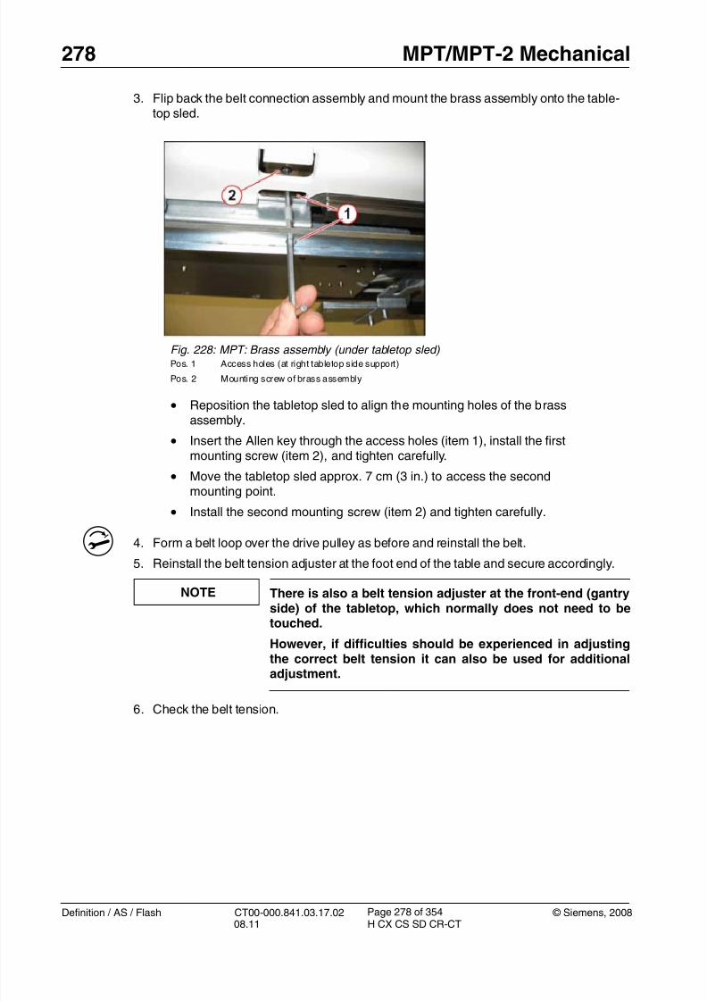
Fig. 45: Undertable view
• The tabletop plate is held by 4 pairs (older revisions: five pairs) of fas-teners which are accessible from below, in the area of the horizontal
drive motors. Five pairs are accessible at a time (see arrows).• Starting with the back pair, remove all eight fasteners (older revisions
ten fasteners), moving the tabletop plate back to gain access to eachpair in turn. <<earlier versions may have a problem with the fastenernear the sensor bracket>>
- PHS horizontal drive motor, material numbers 86 14 344 (PHS-2 and PHS-3) and 8618 386 (PHS-4)
NOTE The horizontal drive is delivered as a set with the drive pulleyand the jaw spanner. We recommend replacing the drive pul-ley together with the motor.
Prerequisites 0
Safety
WARNING [ hz_serdoc_F13G01U12M03 ]
Avoid accident and injury or damage to parts.
Risk of accident and injury!
Read and observe the safety information contained inthe “General” section of this document and/or the“Product specific safety notes”.
Time and Manpower
• 1 person
• Estimated total repair time: 1 hr.
Tools and auxiliary equipment
• Standard service kit
Preliminary steps 0
1. Raise table to height of 125.
2. Switch system toCOMP/ON at the control box.
3. Switch OFF the gantry/PHS power using service push-button S1 in the PDC.
Secure the circuit breakers that S1 switched OFF against unintended switch-on(e.g. lock and tag).
NOTE Read and observe the safety information in the “Prod-uct-specific safety notes” prior to performing service work on the patient table. If the patient table power is switched offfor service work, always secure it against accidental
switch-on.
4. Release the telescopic covers (Telescopic covers: Releasing / p. 43).
5. Remove the lower rear tabletop cover (Tabletop lower rear cover / p. 32).
6. Feed in the table and remove the tabletop covers (Tabletop covers (front andrear) / p. 29).
• At the back of the table, remove plug X3 of the tabletop motor con-
troller (Item1) by pulling the connector. Pull connector X2 from theother end of the controller and remove the 2 wires to the drive motorfrom pins 1 and 3.
• Disconnect plug X731/X732 (item 3).
• Cut all cable ties and remove cable clamps to release all cables to thedrive motor.
For PHS-4 only:
Fig. 47: PHS -4: View from below • Disconnect the cables on the horizontal drive
Horizontal drive, top support (PHS-3 and PHS-4 only) 3.3
• The following instructions are applicable to:
- PHS horizontal drive motor, material number 86 18 394
NOTE The horizontal drive is delivered as a set with the drive pulleyand the jaw spanner. We recommend replacing the drive pul-ley together with the motor.
Prerequisites 0
Safety
WARNING [ hz_serdoc_F13G01U12M03 ]
Avoid accident and injury or damage to parts.
Risk of accident and injury!
Read and observe the safety information contained inthe “General” section of this document and/or the“Product specific safety notes”.
Time and Manpower
• 1 person
• Estimated total repair time: 45 min.
Tools and auxiliary equipment
• Standard service kit
Preliminary steps 0
1. Raise table to height of 125.
2. Switch system toCOMP/ON at the control box.
3. Switch OFF the gantry/PHS power using service push-button S1 in the PDC.
Secure the circuit breakers that S1 switched OFF against unintended switch-on(e.g. lock and tag).
NOTE Read and observe the safety information in the “Prod-uct-specific safety notes” prior to performing service work on the patient table. If the patient table power is switched offfor service work, always secure it against accidentalswitch-on.
4. Release the telescopic covers (Telescopic covers: Releasing / p. 43).
5. Remove the lower rear tabletop cover (Tabletop lower rear cover / p. 32).
6. Feed in the table and remove the tabletop covers (Tabletop covers (front andrear) / p. 29).
Removing 0
1. Release cables.
Fig. 54: View of back
• At the back of the table, remove plug X3 of the support motor control-ler (Item2) by pulling the connector. Pull connector X2 from the otherend of the controller and remove pins 1 and 3.
• Disconnect plug X731/X732 (item 4).
• Cut all cable ties and remove cable clamps to release cables to thedrive motor.
Fig. 55: Support belt adjuster • Release locknut (item 1), loosen clamping bolt (Item 2), and unscrew
the adjuster to release tension on the belt.
• Continue unscrewing the adjuster until the bracket can be removedfrom the frame.
• The procedure to remove the drive pulley for the top support is iden-tical to the procedure for the drive pulley of the tabletop described in(Removing / p. 66)
Fig. 56: Drive pulley of top support Pos. 1 Drive pulley for top support
Fig. 60: Vertical safety bolts • Remove safety bolts from the storage position (Item 1) and install into
vertical lock position (Item 2) using the 14mm hex key.
Fig. 61: Vertical drive motor securing screws
• Using a 6 mm hex key, lower the table by turning the manual lift screw( Item 1 ) counterclockwise until the weight of the table is taken by thesafety bolts. Continue until the bottom of the drive rises 1-2 mm offthe base plate (Item 2).
• Remove the 3 securing bolts (Item 3). Note that the heads areapproximately 8 mm high to allow some freedom of vertical move-
1. Install the cross brace on to the new drive, insert the pin, and tighten the 2 lockingscrews. Rotate the cross brace to obtain the approximate height for reinstallation. Fineadjustments can be made with the manual lift screw.
Attention:Don´t move the spindle higher than the position for reinstallation. Otherwise, theball bearings from the spindle nut will fall out.
2. Place the drive in position and push the cross brace into place between the scissors;again, use a mallet if necessary.
T 3. Install the cross brace locating screws, tighten them to 130 Nm, and install the 2 lockingscrews with torque of 18.6 Nm.
4. Use the manual lift screw to lower the drive motor (clockwise) until it almost touches thebase plate and install the three locating screws applying Loctite 243, leaving 8 mmbetween the head and the drive motor flange.
5. Continue to turn clockwise to raise the table until the safety bolts can be removed. Rein-stall them in the storage positions.
6. Reinstall and adjust connect microswitch S718.
7. Reinstall all plugs and wires to original configuration, using cable ties as necessary.
8. Replace all covers.
Fig. 64: Shaft locking pin • Remove the 2 locking screws (item 1) and withdraw the pin (Item 2).
• Belt tension meter, part no. 8614203 or 7355642.
Preliminary steps 0
1. Raise the table to a height of 125.
2. Switch the system to COMP/ON on the control box.
3. Switch OFF the gantry/PHS power using the service push-button S1 in the PDC.
Secure the circuit breakers that S1 switched off against unintended switch-on(e.g. lock and tag).
NOTE Read and observe the safety information in the “Prod-
uct-specific safety notes” prior to performing service work on the patient table. If the patient table power is switched offfor service work, always secure it against accidentalswitch-on.
4. Remove the switchplate cover (Removing / p. 41).
5. Feed in the table and remove the tabletop covers (Tabletop covers (front andrear) / p. 29).
Fig. 67: Right front cover
• Remove the right front cover (1/ Fig. 67 / p. 86).
Removal 0
1. Move the tabletop approximately 50 cm (20 inches) into the gantry.
NOTE Do not slide the tabletop when the belt pulleys are removed.
1. Push table fully into gantry and feed the end of the belt through the front adjuster.
T2. Ensure that both ends of the belt are fully inserted into securing clamp and install the
two screws and tighten to 6 Nm.
3. Create a loop in the belt as shown above.
4. Reinstall the rear belt tensioner. There is also a front belt tensioner which does not nor-mally need to be adjusted; however, if difficulties are experienced it can also bereleased.
Remove the front right end cap (Front and rear end covers / switchplate cover / p. 40) togain access.
5. Check belt tension.
Fig. 80: Tabletop belt clamp • Pull out the loop in the drive belt.
• Remove the 2 holding screws on the belt clamp (item 1).
- Push the tabletop plate towards the gantry until you achieve a distance of 600 mmbetween the rear pulley and the belt clamp.
- Place the sensor at the center of the trim length over the flat size of the belt (300mm). The distance between sensor and belt should be about 5 to 20 mm.
To learn how to use the tension meter, see the operating instructions delivered withthe meter.
- Start belt vibration by hitting it with the head of a screwdriver.
- Perform the measurement.
- The resonance frequency must be 58 +2 Hz for correct belt tension.
NOTE The value 58 +2 Hz is only valid for a new belt. For othercases, e.g. after replacement of the horizontal motor, the ten-
- PHS top support drive belt, material number 86 14 369
Prerequisites 0
Safety
WARNING [ hz_serdoc_F13G01U12M03 ]
Avoid accident and injury or damage to parts.
Risk of accident and injury!
Read and observe the safety information contained in
the “General” section of this document and/or the“Product specific safety notes”.
Time and Manpower
• 1 person
• Estimated total repair time: 30 min.
Tools and auxiliary equipment
•
Standard service kit• Belt tension meter, for material number see the SPC.
Preliminary steps 0
1. Raise table to height of 125.
2. Switch system to COMP/ON at the control box.
3. Switch OFF the gantry/PHS power using service push-button S1 in the PDC.
Secure the circuit breakers that S1 switched OFF against unintended switch-on
(e.g. lock and tag).
NOTE Read and observe the safety information in the “Prod-uct-specific safety notes” prior to performing service work on the patient table. If the patient table power is switched offfor service work, always secure it against accidentalswitch-on.
4. Release the telescopic covers (Telescopic covers: Releasing / p. 43).
5. Remove the lower rear tabletop cover (Tabletop lower rear cover / p. 32).
NOTE The value 75 +2 Hz is only valid for a new belt. For othercases, e.g. after replacement of the horizontal motor, the ten-sion has to be adjusted to 70 +2 Hz.
4. Adjust the belt tension.
Startup 0
Electrical
1. Switch on circuit breakers F2, F3, F5, F6, F7, and F11 in the PDC A and F2 in the PDCB (not for Definition AS).
First switch the F2, F3, F5, F6 circuit breakers to the “0” position and then to the“1” position.
2. Switch the system to the SYSTEM/ON status at the control box.
Software
n.a
Tune-up
n.a.
Fig. 88: Support belt adjuster
• Use adjustment screw (Item 3) to set deflection of the belt to 20 - 22mm and tighten clamping screw (item 2) to 11 Nm.
- PHS tabletop position sensor, material number 86 14 377
Prerequisites 0
Safety
WARNING [ hz_serdoc_F13G01U12M03 ]
Avoid accident and injury or damage to parts.
Risk of accident and injury!
Read and observe the safety information contained in
the “General” section of this document and/or the“Product specific safety notes”.
Time and Manpower
• 1 person
• Estimated total repair time: 1.5 hours
Tools and auxiliary equipment
•
Standard service kit
Preliminary steps 0
1. Raise table to height of 125.
2. Switch system toCOMP/ON at the control box.
3. Switch OFF the gantry/PHS power using service push-button S1 in the PDC.
Secure the circuit breakers that S1 switched OFF against unintended switch-on(e.g. lock and tag).
NOTE Read and observe the safety information in the “Prod-uct-specific safety notes” prior to performing service work on the patient table. If the patient table power is switched offfor service work, always secure it against accidentalswitch-on.
4. Release the telescopic covers (Telescopic covers: Releasing / p. 43).
5. Remove the lower rear tabletop cover (Tabletop lower rear cover / p. 32).
6. Feed in the table and remove the tabletop covers (Tabletop covers (front andrear) / p. 29).
Top Support Position Sensor and Band (PHS-3 and PHS-4 only) 3.9
• The following instructions are applicable to:
- PHS top support position sensor, material number 86 14 385
Prerequisites 0
Safety
WARNING [ hz_serdoc_F13G01U12M03 ]
Avoid accident and injury or damage to parts.
Risk of accident and injury!
Read and observe the safety information contained in
the “General” section of this document and/or the“Product specific safety notes”.
Time and Manpower
• 1 person
• Estimated total repair time: 1 hr.
Tools and auxiliary equipment
•
Standard service kit• Feeler gauges e.g., material number 80 38 259
Preliminary steps 0
1. Switch system toCOMP/ON at the control box.
2. Switch OFF the gantry/PHS power using service push-button S1 in the PDC.
Secure the circuit breakers that S1 switched OFF against unintended switch-on(e.g. lock and tag).
NOTE Read and observe the safety information in the “Prod-uct-specific safety notes” prior to performing service work on the patient table. If the patient table power is switched offfor service work, always secure it against accidentalswitch-on.
3. Switch off the gantry power using service push-button S1 in PDC A. Secure againstunintended switch-on.
4. Feed in the table and remove the tabletop covers (Tabletop covers (front andrear) / p. 29).
3. Switch OFF the gantry/PHS power using service push-button S1 in the PDC.
Secure the circuit breakers that S1 switched OFF against unintended switch-on(e.g. lock and tag).
NOTERead and observe the safety information in the “Prod-uct-specific safety notes” prior to performing service work on the patient table. If the patient table power is switched offfor service work, always secure it against accidentalswitch-on.
4. Release the telescopic covers (Telescopic covers: Releasing / p. 43).
Replacement 0
NOTE All replaceable switches are attached by two screws.
S717 screws are secured with Loctite.
Removal:
1. Disconnect the wires.
2. Remove the screws; avoid breaking off the screws or damaging the screw head.
3. Remove the switch and the insulating pad.
Installation:
1. Install the new switch and the insulating pad following the removal instructions inreverse order.
2. Tighten the screws with 0.8 Nm.
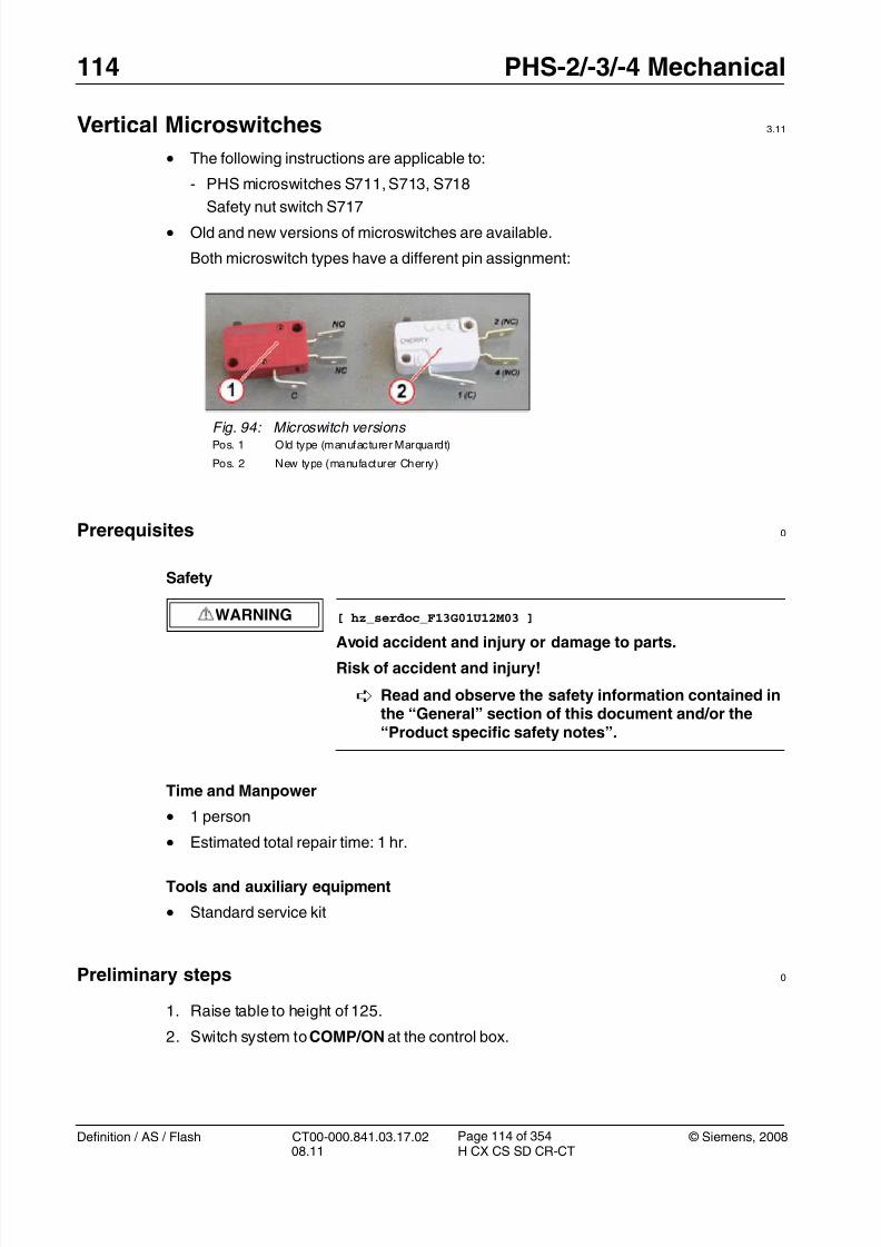
3. Reconnect the wires; observe the different pin assignments of old (Marquardt = red)and new (Cherry = white) microswitch type (1,2/ Fig. 94 / p. 114).
• In normal operation when using the gantry controls, the software lim-its the vertical movement to 10 mm before the mechanical limit; how-ever, this position is referenced to the floor and can be affected byshimming. Therefore, the microswitches are adjusted to operate 5
mm before the mechanical limit. Using the service movementswitches will allow the table to raise or lower until the microswitchoperates.
• Turn on F7 and raise the table using the Service controls (Servicemovement of PHS / p. 21) to a position just before the mechanicallimit.
Do not drive to the mechanical limit.
• Turn off F7.
• Use a 6 mm hex key in the manual lift screw (Manual vertical move-ment of tabletop / p. 22) and move the table to the mechanical limit.Measure the table height from the floor and note down this measure-ment.
• Move the table height to a position 5 mm away from the mechanicallimit.
• Adjust the microswitch by releasing the adjuster nut (Item 1) and slid-ing the carrier so that it operates at this point; use the service move-ment switches to check the final position.
The safety nut switch (Item 2) is installed close to the spindle hous-ing. A shear nut inside the drive will break if too much strain isapplied. If it breaks, the outer bushing drops and S717 is pressed,causing an emergency stop.
If the machine groove is not visible, the complete vertical driveassembly should be replaced.
- The disconnect safety switch is normally operated and will release if the drive motorlifts due to a blockage.
- Adjust the microswitch vertically using the switch screws (shown at [1]) and horizon-tally using the bracket fasteners (shown at [2]).
- The operation can be checked by installing the safety bolts and manually loweringthe table using a 6 mm hex key until the motor lifts (Manual vertical movement oftabletop / p. 22). Check to make sure that the microswitch releases.
Startup 0
Electrical
1. Switch on circuit breakers F2, F3, F5, F6, F7, and F11 in the PDC A and F2 in the PDCB (not for Definition AS).
First switch the F2, F3, F5, F6 circuit breakers to the “0” position and then to the“1” position.
2. Switch the system to the SYSTEM/ON status at the control box.
Software
n.a
Tune-up
n.a
Tests
1. Move the patient table to various vertical positions.
- PHS-2 and PHS-3 power supplies (G701, G702), material number 86 14 500
PHS-4 power supplies, material number 86 14 500 (G701) and material number 8618 113 (G702)
Prerequisites 0
Safety
WARNING [ hz_serdoc_F13G01U12M03 ]
Avoid accident and injury or damage to parts.
Risk of accident and injury!
Read and observe the safety information contained inthe “General” section of this document and/or the“Product specific safety notes”.
Time and manpower
• 1 person
• Estimated total repair time: 30 min.
Tools and Auxiliary Equipment
• Standard service kit
Preliminary steps 0
1. Raise the patient table to height of 125.
2. Switch system to COMP/ON at the control box.
3. Switch OFF the gantry/PHS power using service push-button S1 in the PDC.
Secure the circuit breakers that S1 switched OFF against unintended switch-on(e.g. lock and tag).
NOTE Read and observe the safety information in the “Prod-uct-specific safety notes” prior to performing service work on the patient table. If the patient table power is switched offfor service work, always secure it against accidentalswitch-on.
4. Remove the electronics cover (Table electronics cover / p. 57).
- PHS-3, material number 86 16 034- PHS-4, material number 80 97 144
Prerequisites 0
Safety
WARNING [ hz_serdoc_F13G01U12M03 ]
Avoid accident and injury or damage to parts.
Risk of accident and injury!
Read and observe the safety information contained inthe “General” section of this document and/or the“Product specific safety notes”.
Time and manpower
• 1 person
• Estimated total repair time: 30 min. per item.
Tools and Auxiliary Equipment
• Standard service kit
Preliminary steps 0
1. Raise the patient table to height of 125.
2. Switch system toCOMP/ON at the control box.
3. Switch OFF the gantry/PHS power using service push-button S1 in the PDC.
Secure the circuit breakers that S1 switched OFF against unintended switch-on(e.g. lock and tag).
NOTE Read and observe the safety information in the “Prod-uct-specific safety notes” prior to performing service work on the patient table. If the patient table power is switched offfor service work, always secure it against accidentalswitch-on.
4. Remove the electronics cover (Table electronics cover / p. 57).
1. Installation is in the reverse order of removal.
Startup 0
Electrical
1. Switch on circuit breakers F2, F3, F5, F6, F7, and F11 in the PDC A and F2 in the PDCB (not for Definition AS).
First switch the F2, F3, F5, F6 circuit breakers to the “0” position and then to the
“1” position.
Fig. 104: Location of relays, contactor, and diode block
• Remove wires, check that the markings are clear and understand-able.
• K711 vertical brake relay (shown at [1]), K709 AC power sensingrelay (shown at [2]), and K701 safety contactor (shown at [3]) are allreleased by removing the clamp on the respective mounting rail (e.g.[5]).
• The rectifier diode V702 (shown at [4]) is secured by a single fas-tener.
NOTE PHS relevant parameters are stored in the configuration tableT3C. Table T3C is stored on the PHS-LMAS board - Source:Volatile. If the LMAS board is replaced the original T3C has to
be restored on the new LMAS; otherwise, the PHS may notfunction correctly.
There are two ways to save the original T3C table
1. Prior to removing the old LMAS board, perform function“Service > Control > table load/modify”. Select table T3C,set radio button “Volatile” and press <Go> to display thetable. Select radio button “Persistent” and press <Go> toback it up on the UMAS board.
2. The original T3C is already stored on the UMAS becausethis step is performed automatically with every PHS
adjustment (vertical or horizontal). You may check if aPHS adjustment was performed in the past.
Restoring the T3C table on the new LMAS board:
Use function “Service > Control > table load/modify”. Selecttable T3C, set radio button “Persistent” and press <GO> todisplay the table stored at the UMAS. Select radio button“Volatile” and press <Go> to download it onto the LMAS.
• Select Local_Service > TuneUp.
• Select FRU Replace.
• Select PHS - LMAS.
• Press <Go> to start the tour.
- Save table T3C prior to replacing the part and restore table T3C after replacement asdescribed in the above note.
The Guided Tour has been completed successfully if the TC3 is restored on thenew component.
Preliminary steps 0
1. Raise the patient table to maximum height for better access.
2. Switch system to COMP/ON at the control box.
3. Switch OFF the gantry/PHS power using service push-button S1 in the PDC.
Secure the circuit breakers that S1 switched OFF against unintended switch-on(e.g. lock and tag).
NOTE Read and observe the safety information in the “Prod-uct-specific safety notes” prior to performing service work on the patient table. If the patient table power is switched offfor service work, always secure it against accidental
switch-on.
4. Remove the electronics cover (Table electronics cover / p. 57).
Removing 0
1. Remove LMAS-2/-3 board.
NOTE The figure below shows the LMAS-2 board as an example.
The attachment points of the LMAS-3 are identical.
Installation 0
T 1. Secure assembly to electronics tray with the 2 nuts and tighten to 3 Nm.
2. Reinstall all connectors.
Note: Make sure that cable X301 is plugged into X302. Cable X302 does not getplugged into LMAS-2 and LMAS-3.
- PHS-3, material number 86 16 034- PHS-4, material number 80 97 144
Prerequisites 0
Safety
WARNING [ hz_serdoc_F13G01U12M03 ]
Avoid accident and injury or damage to parts.
Risk of accident and injury!
Read and observe the safety information contained inthe “General” section of this document and/or the“Product specific safety notes”.
Time and manpower
• 1 person
• Estimated total repair time: 1 hr.
Tools and Auxiliary Equipment
• Standard service kit
Preliminary steps 0
1. Raise table to height of 125.
2. Switch system to COMP/ON at the control box.
3. Switch OFF the gantry/PHS power using service push-button S1 in the PDC.
Secure the circuit breakers that S1 switched OFF against unintended switch-on(e.g. lock and tag).
NOTE Read and observe the safety information in the “Prod-uct-specific safety notes” prior to performing service work on the patient table. If the patient table power is switched offfor service work, always secure it against accidentalswitch-on.
4. Release the telescopic covers (Telescopic covers: Releasing / p. 43).
5. Remove the telescopic covers (Telescopic covers: Removing / p. 52).
6. Remove the electronics cover (Table electronics cover / p. 57).
- PHS vertical motor controller LUST, material number 86 14 518
NOTE Do not replace LMAS and motor controllers at the same time!
If you are uncertain which component is causing the prob-lem, finish replacing one part before you replace the next.
Prerequisites 0
Safety
WARNING [ hz_serdoc_F13G01U12M03 ]
Avoid accident and injury or damage to parts.
Risk of accident and injury!
Read and observe the safety information contained inthe “General” section of this document and/or the“Product specific safety notes”.
Time and manpower
• 1 person
• Estimated total repair time: 45 min.
Tools and Auxiliary Equipment
• Standard service kit
Preliminary steps 0
1. Raise the patient table to height of 125.2. Switch system toCOMP/ON at the control box.
3. Switch OFF the gantry/PHS power using service push-button S1 in the PDC.
Secure the circuit breakers that S1 switched OFF against unintended switch-on(e.g. lock and tag).
NOTE Read and observe the safety information in the “Prod-uct-specific safety notes” prior to performing service work on the patient table. If the patient table power is switched offfor service work, always secure it against accidental
NOTE Read and observe the safety information in the “Prod-uct-specific safety notes” prior to performing service work on the patient table. If the patient table power is switched offfor service work, always secure it against accidental
switch-on.
4. Feed in the tabletop plate and remove the tabletop plate covers (Tabletop covers (frontand rear) / p. 29).
Removing 0
1. Remove motor controller.
Fig. 110: View of back
• Tabletop controller is at the back of the table (item 1), tabletop sup-port controller is at the front (item 2).
Read and observe the safety information contained in
the “General” section of this document and/or the“Product specific safety notes”.
Time and manpower
• 1 person
• Estimated total repair time: 45 min.
Tools and auxiliary equipment
•
Standard service kit
Preliminary steps 0
1. Lower the telescopic covers as described in (Telescopic covers: Releasing / p. 43)
2. Switch system toCOMP/ON at the control box.
3. Switch OFF the gantry/PHS power using service push-button S1 in the PDC.
Secure the circuit breakers that S1 switched OFF against unintended switch-on(e.g. lock and tag).
NOTE Read and observe the safety information in the “Prod-uct-specific safety notes” prior to performing service work on the patient table. If the patient table power is switched offfor service work, always secure it against accidentalswitch-on.
4. Switch off the gantry power using service push-button S1 in PDC A. Secure againstunintended switch-on.
Read and observe the safety information contained in
the “General” section of this document and/or the“Product specific safety notes”.
Time and manpower
• 1 person
• Estimated total repair time: 20 min.
Tools and Auxiliary Equipment
•
Standard service kit
Preliminary steps 0
1. Raise the patient table to height of 125.
2. Shut down the system software (click <SYSTEM> and select <END> in the user mainmenu).
3. Click Shutdown System
4. Confirm with Yes in the dialog box displayed.
NOTE Read and observe the safety information in the “Prod-uct-specific safety notes” prior to performing service work on the patient table. If the patient table power is switched offfor service work, always secure it against accidentalswitch-on.
NOTE On PMMs with revision level 05 and higher, the CanOpen ter-
minator is installed in the module. Therefore, the externalresistor in plug X2 is no longer required.
Do not install plug X2!
Startup 0
Electrical
1. Press the Sys On key on the control box. The whole system is ready for operation whenthe Sys On LED is lit and the operating elements on the control box are backlit.
Software
1. If the system shows a fatal firmware mismatch, the new firmware has to be installed:
Go to Local Service > Control > Firmware to load the current firmware version.
Tune-up
n.a.
Tests
1. Activate the ECG Monitor Demo mode.
- Select: Control > Configuration
- Select: Heartview
- Mark the checkbox “ECG Monitor Demo mode”
- Press <Apply>
An ECG pulse must be seen on the gantry display.
2. Deactivate the ECG Monitor Demo mode by deselecting the checkbox in the Heartview
Read and observe the safety information contained in
the “General” section of this document and/or the“Product specific safety notes”.
Time and manpower
• 1 person
• Estimated total repair time: 45 min.
Tools and Auxiliary Equipment
•
Standard service kit
Preliminary steps 0
1. Raise table to height of 125.
2. Switch system toCOMP/ON at the control box.
3. Switch OFF the gantry/PHS power using service push-button S1 in the PDC.
Secure the circuit breakers that S1 switched OFF against unintended switch-on(e.g. lock and tag).
NOTE Read and observe the safety information in the “Prod-uct-specific safety notes” prior to performing service work on the patient table. If the patient table power is switched offfor service work, always secure it against accidentalswitch-on.
4. Feed in the tabletop plate and remove the tabletop covers (Tabletop covers (front andrear) / p. 29).
1. Remove the PMM module (PMM Module / p. 151) and cut accessible cable ties.Remove the plug through the slot in the tabletop. Any ties that cannot be accessed atthe moment can be cut later.
2. Move the tabletop to the position shown in the figure below.
Fig. 116: Position for removing the bracket
3. Remove the bracket for the PMM cable.
- Loosen the attachment screw at the rear (2 /Fig. 117 / p. 155).
- Loosen the two screws on the bottom (1/ Fig. 118 / p. 155)
- PMM cable vertical lift, material number 86 14 740
Prerequisites 0
Safety
WARNING [ hz_serdoc_F13G01U12M03 ]
Avoid accident and injury or damage to parts.
Risk of accident and injury!
Read and observe the safety information contained in
the “General” section of this document and/or the“Product specific safety notes”.
Time and manpower
• 1 person
• Estimated total repair time: 1 hr.
Tools and Auxiliary Equipment
•
Standard service kit
Preliminary steps 0
1. Raise table to height of 125.
2. Switch system toCOMP/ON at the control box.
3. Switch OFF the gantry/PHS power using service push-button S1 in the PDC.
Secure the circuit breakers that S1 switched OFF against unintended switch-on(e.g. lock and tag).
NOTE Read and observe the safety information in the “Prod-uct-specific safety notes” prior to performing service work on the patient table. If the patient table power is switched offfor service work, always secure it against accidentalswitch-on.
4. Release the telescopic covers (Telescopic covers: Releasing / p. 43).
5. Remove the electronics cover (Table electronics cover / p. 57).
6. Remove the telescopic covers (Telescopic covers: Removing / p. 52).
7. Remove the lower rear tabletop cover (Tabletop lower rear cover / p. 32).
8. Feed in the tabletop plate and remove the tabletop covers (Tabletop covers (front andrear) / p. 29).
Removing0
1. Release plug at electronics tray.
Fig. 121: PMM plug location
• Release plug marked “PMM” (item 1) and cut cable ties up to verticalflexible conduit.
• Cut cable ties holding cables between horizontal and vertical flexibleconduits.
• Pull the cable out of the vertical flexible conduit. Removal from thispoint may involve partial withdrawal of the PHS cable set; refer toinstructions on replacement of PHS cable set (PHS CableSet / p. 162)
1. Installation is in the reverse order of removal. Prior to installing the cable ties, refer to
installing the PHS cable set (PHS Cable Set / p. 162)and follow instructions regardingcable placement in the flexible conduit.
2. Reinstall all covers.
Fig. 122: PMM cable at support end
•Cut cable ties, release plug marked “PMM” (Item 1), and feed plugunder support bridge (Item 2) <<Later models have removable postin bridge>>.
• Cable can now be pulled out of the tabletop support flexible conduit,again refer to instructions on the replacement of PHS cable set (PHSCable Set / p. 162).
- PHS cable set PHS3 and PHS-4, material number 86 14 724
Prerequisites 0
Safety
WARNING [ hz_serdoc_F13G01U12M03 ]
Avoid accident and injury or damage to parts.
Risk of accident and injury!
Read and observe the safety information contained in
the “General” section of this document and/or the“Product specific safety notes”.
Time and manpower
• 1 person
• Estimated total repair time: 1 1/2 hours.
Tools and Auxiliary Equipment
•
Standard service kit
Preliminary steps 0
1. Raise table to height of 125.
2. Switch system toCOMP/ON at the control box.
3. Switch OFF the gantry/PHS power using service push-button S1 in the PDC.
Secure the circuit breakers that S1 switched OFF against unintended switch-on(e.g. lock and tag).
NOTE Read and observe the safety information in the “Prod-uct-specific safety notes” prior to performing service work on the patient table. If the patient table power is switched offfor service work, always secure it against accidentalswitch-on.
4. Release the telescopic covers (Telescopic covers: Releasing / p. 43).
5. Remove the electronics cover (Table electronics cover / p. 57).
6. Remove the telescopic covers (Telescopic covers: Removing / p. 52).
7. Remove the lower rear tabletop cover (Tabletop lower rear cover / p. 32).
8. Feed in the tabletop plate and remove the tabletop covers (Tabletop covers (front andrear) / p. 29).
Removing0
1. Starting at the electronics tray, work up towards the back of the table. Cut all cable tiesto release the PHS cables.
2. Remove plugs at electronics tray.
Fig. 123: Cable set connections at electronics tray
• At the electronics tray, remove the following connectors:
- X712, X713, X714 at the electronics tray (item 1).
- X725 at the electronics tray (Item 2).
- X22 at the table master board (LMAS) (Item 3)
- PE connector (Item 4).
- The PMM cable is not included in the scope of delivery, but shouldalso be removed from the flexible conduits for ease of reinstalla-tion. Refer to Replacement of Parts for vertical PMM cable (PMMcable (vertical lift) / p. 158).
7. Cut all cable ties and remove all cable clamps; the cable set can now be removed.
Installation 0
1. Lay the new cable in place, include the PMM cable and service panel cable, and makesure the cables are parallel and not crossed. Then push them into the flexible conduitsuntil fully inserted and the plastic “leaves” have sprung back and are touching again.
2. Reconnect all plugs and ground connections, reinstall support post.
3. Replace cable ties. Ensure that cables in the flexible conduits are not to taught andhave sufficient freedom to flex fully. Check again that the cables in the flexible conduitare parallel and do not cross each other.
4. Reinstall all covers.
Fig. 127: View from back, PHS cable loom replacement
• At the back of the table, remove the following connectors:
- X5, X6 at one end of each motor controller.
- X1,X2 at the other end of each motor controller. At both controllersalso remove the 4 wires (to motor) from connector X2 pins 1, 3.
- X752 to back switchplate (Item 1).
- B721 and B731 to the horizontal motors (Item 2).
- PE connectors (item 3).
- Disconnect plug B722 to support sensor and B732 to top sensor.
Read and observe the safety information contained inthe “General” section of this document and/or the“Product specific safety notes”.
Time and manpower
• 1 person
• Estimated total repair time: 1 hour
Tools and auxiliary equipment
• Standard service kit
Preliminary Steps 0
1. Move the table into the uppermost position.
2. Move the tabletop into the gantry.
3. Switch system to the COMP/ON status at the control box.
4. Switch off the gantry/PHS power using the S1 service button in the PDC. Secureagainst unintended switch-on the breakers that S1 switched off (e.g. lock and tag).
5. Remove the back cover and the back basin cover.
Read and observe the safety information contained inthe “General” section of this document and/or the“Product specific safety notes”.
Time and manpower
• 1 person
• Estimated total repair time: 15 min.
Tools and auxiliary equipment
• Standard service kit
Preliminary Steps 0
1. Move the table into the uppermost position.
2. Switch system to the COMP/ON status at the control box.
3. Switch off the gantry/PHS power using the S1 service button in the PDC. Secureagainst unintended switch-on the breakers that S1 switched off (e.g. lock and tag).
Removal 0
Back basin
NOTE For easier removal of the back basin it is recommended toremove the back cover first.
Read and observe the safety information contained inthe “General” section of this document and/or the“Product specific safety notes”.
Time and manpower
• 1 person
• Estimated total repair time: 15 min.
Tools and auxiliary equipment
• Standard service kit
Preliminary Steps 0
1. Move the table into the uppermost position.
2. Switch system to the COMP/ON status at the control box.
3. Switch off the gantry/PHS power using the S1 service button in the PDC. Secureagainst unintended switch-on the breakers that S1 switched off (e.g. lock and tag).
Read and observe the safety information contained inthe “General” section of this document and/or the“Product specific safety notes”.
Time and manpower
• 1 person
• Estimated total repair time: 1 hr.
Tools and auxiliary equipment
• Standard service kit
Preliminary Steps 0
1. Move the table into the uppermost position.
2. Move the tabletop into the gantry.
3. Switch system to the COMP/ON status at the control box.
4. Switch off the gantry/PHS power using the S1 service button in the PDC. Secureagainst unintended switch-on the breakers that S1 switched off (e.g. lock and tag).
5. Remove the cover of the electronics tray.
Removal 0
1. Remove all cable connections of the component which has to be replaced:
2. Loosen the attachment screws of the component which has to be replaced.
Read and observe the safety information contained inthe “General” section of this document and/or the“Product specific safety notes”.
Time and manpower
• 1 person
• Estimated total repair time: 1 hr.
Tools and auxiliary equipment
• Standard service kit
Preliminary Steps 0
1. Move the table into the uppermost position.
2. Switch system to the COMP/ON status at the control box.
3. Switch off the gantry/PHS power using the S1 service button in the PDC. Secureagainst unintended switch-on the breakers that S1 switched off (e.g. lock and tag).
4. Remove the back basin.
5. Remove the front cover
6. Move the tabletop manually into the gantry.
7. Remove the rear tabletop cover (this is required for the adjustment of the belt tension).
Removal 0
NOTE The horizontal drive assembly spare part is delivered as apreassembled component consisting of the motor, clutch,and pulley.
1. Cut the cable ties of the cables to the drive motor and the clutch.
2. Remove the cable connections of the horizontal drive on the motor controller.
Read and observe the safety information contained inthe “General” section of this document and/or the“Product specific safety notes”.
Time and manpower
• 1 person
• Estimated total repair time: 1.5 hours.
Tools and auxiliary equipment
• Standard service kit
• Belt tension meter, refer to SPC for the material number.
Preliminary Steps 0
1. Move the table into the uppermost position.
2. Move the tabletop into the gantry.
3. Switch system to the COMP/ON status at the control box.
4. Switch off the gantry/PHS power using the S1 service button in the PDC. Secureagainst unintended switch-on the breakers that S1 switched off (e.g. lock and tag).
5. Remove the front covers.
6. Remove the back cover.
7. Remove the rear tabletop cover.
Removal 0
1. Release the tension of the toothed belt
a) Loosen the locknut.
b) Loosen the 2 attachment screws from below.
c) Release the belt tension by turning the adjustment screw counterclockwise.
2. Measuring the belt tension using the belt tension meter:
The measurement has to be performed from above.Push the tabletop towards the gantry until you achieve a distance of 600 mm betweenthe center of the rear pulley and the belt clamp.
Place the sensor of the belt tension meter at the center of the trim length (= 300 mmfrom rear pulley) over the flat side of the belt. The distance between the sensor of thebelt tension meter and the belt should be about 5 to 20 mm.
Fig. 150: Measuring the belt tension Pos. 1 Rear pulley
Pos. 2 Belt clamp
Pos. 3 Measuring point
To learn how to use the tension meter, see the operating instructions delivered with themeter.
- Start belt vibration by hitting it with the head of a screwdriver.
- Perform the measurement.
- The resonance frequency must be 45 +2 Hz for correct belt tension.
NOTE The value 45 +2 Hz is only valid when the belt is replaced.When using the same belt, e.g. after replacement of the hori-zontal motor, the tension has to be adjusted to 39 +2 Hz.
3. Adjust the belt tension
- Adjust the belt tension with the adjusting screw
Read and observe the safety information contained inthe “General” section of this document and/or the“Product specific safety notes”.
Time and manpower
• 1 person
• Estimated total repair time: 1 hour.
Tools and auxiliary equipment
• Standard service kit
Preliminary Steps 0
1. Move the table into the uppermost position.
2. Switch system to the COMP/ON status at the control box.
3. Switch off the gantry/PHS power using the S1 service button in the PDC. Secureagainst unintended switch-on the breakers that S1 switched off (e.g. lock and tag).
Covers described in this document.• Tabletop covers (front and rear): (not shown) These are the covers underneath the
tabletop plate covering the support. They must be removed to gain access to the hori-zontal drive motors, tabletop belt, horizontal sensors, and horizontal controllers.
• Telescopic covers: (Item 1) The telescopic covers are divided into 4 segment pairs:
The whole cover assembly can be released at the tabletop and lowered to the tablebase for certain service operations at the tabletop and/or for complete removal.
For most service operations at the table base, the whole cover assembly can bereleased at the bottom (foot covers) and lifted with the help of a service tool (adjustable
strap with two hooks) to gain access to all components (e.g. electronics, vertical driveetc.) in the table base.
• Switchplate cover (Item 2) This cover must be removed to gain access to the switch-plate and the horizontal drive motors and belts.
• Side support. (Item 3) These are the aluminum covers on each side of the tabletopplate. They are normally only removed if damaged.
• Rear-end covers (Item 4) These are at each foot end of the side support covers.
NOTE: Both covers (left/right) are loosely mounted together in the middle. For removalboth covers must be removed.
• Front-end covers. (Item 5) These are at each front end (gantry side) of the side sup-
port covers.
• Handle / PMM box. (Item 6) This cover at the foot end of the tabletop sled incorporatesthe handle bar for manual tabletop movement. If the system has the PMM optioninstalled then this cover represents the PMM box (including the PMM electronics andterminals).
NOTE: For Replacement of Parts refer to section “MPT Electronics - PMM Box” (PMMBox / p. 331)
Read and observe the safety information contained inthe “General” section of this document and/or the“Product specific safety notes”.
Time and Manpower
• 1 person
• Estimated total repair time: 10 min.
Tools and auxiliary equipment
• Standard service kit
Preliminary steps 0
1. Raise the patient table to maximum height (position 125) via the service buttons or, ifnot possible, via the mechanical lift.
2. Switch system to COMP/ON at the control box.
3. Switch OFF the gantry/PHS power using service push-button S1 in the PDC.
Secure the circuit breakers that S1 switched OFF against unintended switch-on(e.g. lock and tag).
NOTE Read and observe the safety information in the “Prod-uct-specific safety notes” prior to performing service work on the patient table. If the patient table power is switched offfor service work, always secure it against accidentalswitch-on.
For rear tabletop cover:
• Move the tabletop plate toward the gantry until all six mounting screws are accessible.
Read and observe the safety information contained in
the “General” section of this document and/or the“Product specific safety notes”.
Time and Manpower
• 1 person
• Estimated total repair time: 10 min.
Tools and auxiliary equipment
•
Standard service kit
Preliminary steps 0
1. Raise the patient table to maximum height (position 125) via the service buttons or, ifnot possible, via the mechanical lift.
2. Switch system to COMP/ON at the control box.
3. Switch OFF the gantry/PHS power using service push-button S1 in the PDC.
Secure the circuit breakers that S1 switched OFF against unintended switch-on
(e.g. lock and tag).
NOTE Read and observe the safety information in the “Prod-uct-specific safety notes” prior to performing service work on the patient table. If the patient table power is switched offfor service work, always secure it against accidentalswitch-on.
- Side support cover (left/right), material number 86 18 188
Prerequisites 0
Safety
WARNING [ hz_serdoc_F13G01U12M03 ]
Avoid accident and injury or damage to parts.
Risk of accident and injury!
Read and observe the safety information contained in
the “General” section of this document and/or the“Product specific safety notes”.
Time and Manpower
• 1 person
• Estimated total repair time: 30 min.
Tools and auxiliary equipment
•
Standard service kit
Preliminary steps 0
1. Raise the patient table to maximum height (position 125) via the service buttons or, ifnot possible, via the mechanical lift.
2. Switch system to COMP/ON at the control box.
3. Switch OFF the gantry/PHS power using service push-button S1 in the PDC.
Secure the circuit breakers that S1 switched OFF against unintended switch-on
(e.g. lock and tag).
NOTE Read and observe the safety information in the “Prod-uct-specific safety notes” prior to performing service work on the patient table. If the patient table power is switched offfor service work, always secure it against accidentalswitch-on.
4. Remove the rear covers of the side support. (Front and rear covers (left/right) / p. 220)
5. Remove the tabletop plate. (Tabletop plate / p. 238)
6. Remove the front covers of the side support. (Front and rear covers (left/right) / p. 220)
- Front cover right, material number 86 18 196- Rear cover left, material number 86 18 220
- Rear cover right, material number 86 18 212
Prerequisites 0
Safety
WARNING [ hz_serdoc_F13G01U12M03 ]
Avoid accident and injury or damage to parts.
Risk of accident and injury!
Read and observe the safety information contained inthe “General” section of this document and/or the“Product specific safety notes”.
Time and Manpower
• 1 person
• Estimated total repair time: 15 min.
Tools and auxiliary equipment
• Standard service kit
Preliminary steps 0
1. Raise the patient table to maximum height (position 125) via the service buttons or, ifnot possible, via the mechanical lift.
2. Switch system toCOMP/ON at the control box.
3. Switch OFF the gantry/PHS power using service push-button S1 in the PDC.
Secure the circuit breakers that S1 switched OFF against unintended switch-on(e.g. lock and tag).
NOTE Read and observe the safety information in the “Prod-uct-specific safety notes” prior to performing service work on the patient table. If the patient table power is switched offfor service work, always secure it against accidentalswitch-on.
NOTE Read and observe the safety information in the “Prod-uct-specific safety notes” prior to performing service work on the patient table. If the patient table power is switched offfor service work, always secure it against accidental
switch-on.
Removing 0
1. Releasing the base covers from the table base:
2. Installing the service strap:
NOTE The required strap is delivered with the MPT as a service aid.
• Remove the locking screw at the foot end of the base covers (Item 1).
• Pull up the base cover by hand to release the bolts from the grom-mets at the table base. Each base cover half-segment (left/right) hasthree bolts (one between the two foot switches and one each at thefoot end and the front).
- Top cover (right), material number 86 18 329- Upper telescopic cover (left/right), material number 86 18 352
- Lower telescopic cover (left/right), material number 86 18 345
- Foot cover (left), material number 86 16 311
- Foot cover (right), material number 86 16 303
Prerequisites 0
Safety
WARNING [ hz_serdoc_F13G01U12M03 ]
Avoid accident and injury or damage to parts.
Risk of accident and injury!
Read and observe the safety information contained inthe “General” section of this document and/or the“Product specific safety notes”.
Time and Manpower
• 1 person
• Estimated total repair time: 30 min.
Tools and auxiliary equipment
• Standard service kit
Preliminary steps 0
1. If possible, lower the patient table to minimum height via the service buttons.2. Switch system toCOMP/ON at the control box.
3. Switch OFF the gantry/PHS power using service push-button S1 in the PDC.
Secure the circuit breakers that S1 switched OFF against unintended switch-on(e.g. lock and tag).
NOTE Read and observe the safety information in the “Prod-uct-specific safety notes” prior to performing service work on the patient table. If the patient table power is switched offfor service work, always secure it against accidentalswitch-on.
Fig. 180: MPT: Top cover (gantry-side) Pos. 1 Top cover (right half-shell)
Pos. 2 Bolt & grommet locations
• Pull down the top cover at the gantry side until the two bolts arereleased from the grommets. (item 2 and arrow)
• Hold on to the cover and step to the right side of the table.
Fig. 181: MPT: Top cover (foot-end side) Pos. 1 Top cover (right half-shell)
Pos. 2 Pin and keyway locations
• Slightly lift the right half-shell of the top cover at the foot end of thetable to release the pin at the keyway (item 2) and pull it toward theside of the table to unhook and remove it. (see arrow)
• Remove the left half-shell of the top cover the same way from theother side of the table.
This chapter describes the removal and replacement of the following MPT mechanicalcomponents:
• Tabletop plates (Standard, RTP, and Bariatric type plates)
• Vertical drive unit
• Horizontal drive motors (tabletop and top support drive motor)
• Horizontal drive belts (tabletop and top support drive belt)
• Position sensors (tabletop wire sensor, top support magnetic sensor, and verticalposition sensor)
• Vertical safety and limit switches (upper and lower limit switches and vertical con-nect safety switch)
NOTE The safety nut switch on the vertical drive is NOT an FRU!
If the safety nut switch is activated the complete verticaldrive must be replaced!
NOTE The adjustment procedures for parts that require softwarecalibration will be covered by the “FRU Replacement” proce-dure under “Local Service” > “Tune-up”.
1. Check the coding screws at the new tabletop plate:
2. Lift the new tabletop onto the table and position it on the tabletop so that the aluminumblock of the tabletop plate sits on the sliding mechanism (mechanical interface) of thetabletop.
3. Lift the tabletop at the gantry side approx. 30 cm (1 ft.) and push it toward the foot end of
the table until it slides fully down the sliding mechanism and reaches a mechanical stop.4. Lower the tabletop plate at the gantry-side onto the tabletop.
The tabletop plate is automatically secured to the tabletop by the 2 locking pinsand the sliding mechanism.
NOTEThe tabletop plate and plate type will be recognized automat-ically by the software through the coding switches at thetabletop sled.
If incorrect or invalid coding (e.g. tabletop plate missing, cod-ing screws in incorrect location or not activating the switch)is recognized, the table will not go into standby and tablemovement will be blocked.
Tune-up
n.a
Tests
1. Check horizontal movements of the tabletop via the buttons at the gantry control panel.
Read and observe the safety information contained in
the “General” section of this document and/or the“Product specific safety notes”.
Time and Manpower
• 1 person
• Estimated total repair time: 2 hr.
Tools and auxiliary equipment
•
Standard service kit• Loctite 243
• Size 10 hex nut socket (for manual lift)
• Mallet
Preliminary steps 0
1. Raise the patient table to maximum height (position 125) via the service buttons or, ifnot possible, via the mechanical lift.
2. Switch system toCOMP/ON at the control box.
3. Switch OFF the gantry/PHS power using service push-button S1 in the PDC.
Secure the circuit breakers that S1 switched OFF against unintended switch-on(e.g. lock and tag).
NOTE Read and observe the safety information in the “Prod-uct-specific safety notes” prior to performing service work on the patient table. If the patient table power is switched offfor service work, always secure it against accidentalswitch-on.
1. Install the cross brace onto the new drive, insert the shaft pin, and tighten the 2 lockingscrews of the shaft pin. Rotate the cross brace to obtain the approximate height for rein-stallation. Fine adjustments can be made with the manual lift screw.
2. Place the drive in position and push the cross brace into place between the scissors;again, use a mallet if necessary.
T 3. Install the cross brace locating screws, tighten them to 130 Nm, and install the 2 lockingscrews with torque of 18.6 Nm.
4. Use the manual lift screw to lower the drive motor (clockwise) until it almost touches thebase plate and install the 3 locating screws applying Loctite 243, leaving 8 mm betweenthe head and the drive motor flange.
5. Continue to turn clockwise to raise the table until the safety bolts can be removed. Rein-stall them in the storage positions.
6. Reinstall the bracket of the connect safety switch S718 to the table base and adjust the
switch to the switch flag on the new vertical drive.
Refer to adjustment instructions for the connect safety switch.
7. Reinstall all plugs and wires to original configuration. Use cable ties as necessary.
8. Reinstall the table covers.
Fig. 202: Shaft locking pin • Remove the 2 locking screws (item 1) and withdraw the pin (Item 2).
NOTE Read and observe the safety information in the “Prod-uct-specific safety notes” prior to performing service work on the patient table. If the patient table power is switched offfor service work, always secure it against accidental
switch-on.
4. Remove the tabletop plate. (Tabletop plate / p. 238)
5. Remove the left/right rear covers of the side support (one plastic cap and screw eachside).
6. Feed the tabletop sled towards the gantry to access all 6 mounting screws of the reartabletop cover.
7. Remove the rear tabletop cover (6 plastic caps and Allen screws). (Tabletop covers(front and rear) / p. 209)
8. Remove the switchplate cover at the foot end of the tabletop. (Switchplatecover / p. 213)
• Remove the connector X3 from the motor controller U731 (item 1).
• Remove the connector X2 from the corresponding motor controllerand remove the 2 wires to the drive motor from pins 1 and 3 (= motorbrake connection).
• Disconnect the cable connection X731 (item3)
• Cut all cable ties and remove cable clamp (shielding of orange cable)to release all cables to the drive motor.
For MPT-2 only:
Fig. 204: MPT-2: View from below • Disconnect the cables on the horizontal drive.
- PHS horizontal drive motor, material number 86 18 394
NOTE The horizontal drive is delivered as a set with the drive pulleyand the jaw spanner. We recommend replacing the drive pul-ley together with the motor.
Prerequisites 0
Safety
WARNING [ hz_serdoc_F13G01U12M03 ]
Avoid accident and injury or damage to parts.
Risk of accident and injury!
Read and observe the safety information contained inthe “General” section of this document and/or the“Product specific safety notes”.
Time and Manpower
• 1 person
• Estimated total repair time: 45 min.
Tools and auxiliary equipment
• Standard service kit
• Loctite 243
Preliminary steps 0
1. Raise the patient table to maximum height (position 125).2. Switch system toCOMP/ON at the control box.
3. Switch OFF the gantry/PHS power using service push-button S1 in the PDC.
Secure the circuit breakers that S1 switched OFF against unintended switch-on(e.g. lock and tag).
NOTE Read and observe the safety information in the “Prod-uct-specific safety notes” prior to performing service work on the patient table. If the patient table power is switched offfor service work, always secure it against accidental
2. Switch the system to COMP/ON on the control box.
3. Switch OFF the gantry/PHS power using the service push-buttonS1 in the PDC. Secure the circuit breakers that S1 switched off against unintended switch-on
(e.g. lock and tag).
NOTE Read and observe the safety information in the “Prod-uct-specific safety notes” prior to performing service work on the patient table. If the patient table power is switched offfor service work, always secure it against accidentalswitch-on.
4. Remove the switchplate cover (Removing / p. 41).
5. Feed in the table and remove the tabletop covers (Tabletop covers (front andrear) / p. 29).
6. Remove the front cover of the right side support.
Fig. 214: Right front cover
Removal 0
1. Move the tabletop approximately 50 cm (20 inches) into the gantry.
NOTE Do not slide the tabletop when the belt pulleys are removed.
Read and observe the safety information contained in
the “General” section of this document and/or the“Product specific safety notes”.
Time and Manpower
• 1 person
• Estimated total repair time: 45 min.
Tools and auxiliary equipment
•
Standard service kit• Loctite 243
• Belt tension meter, for material number see the SPC.
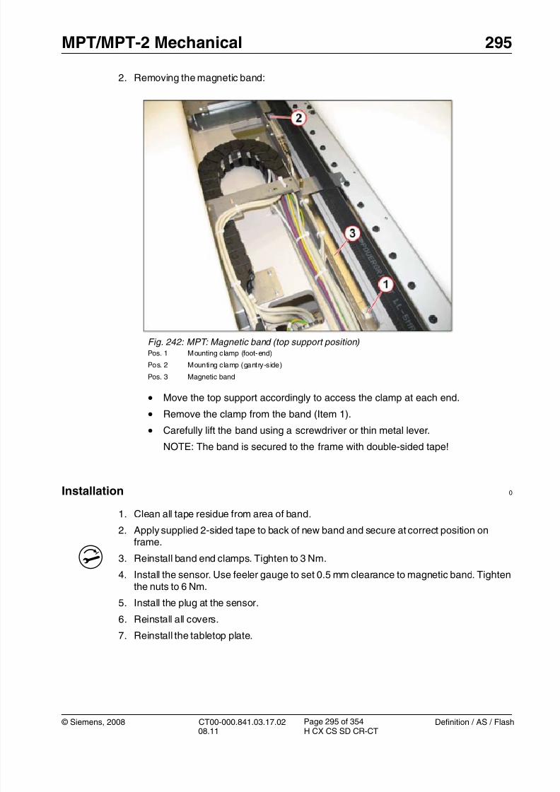
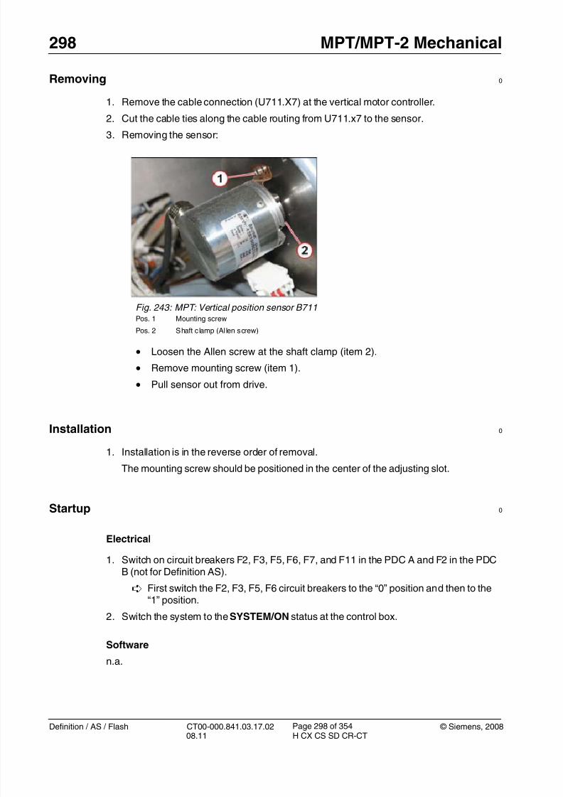
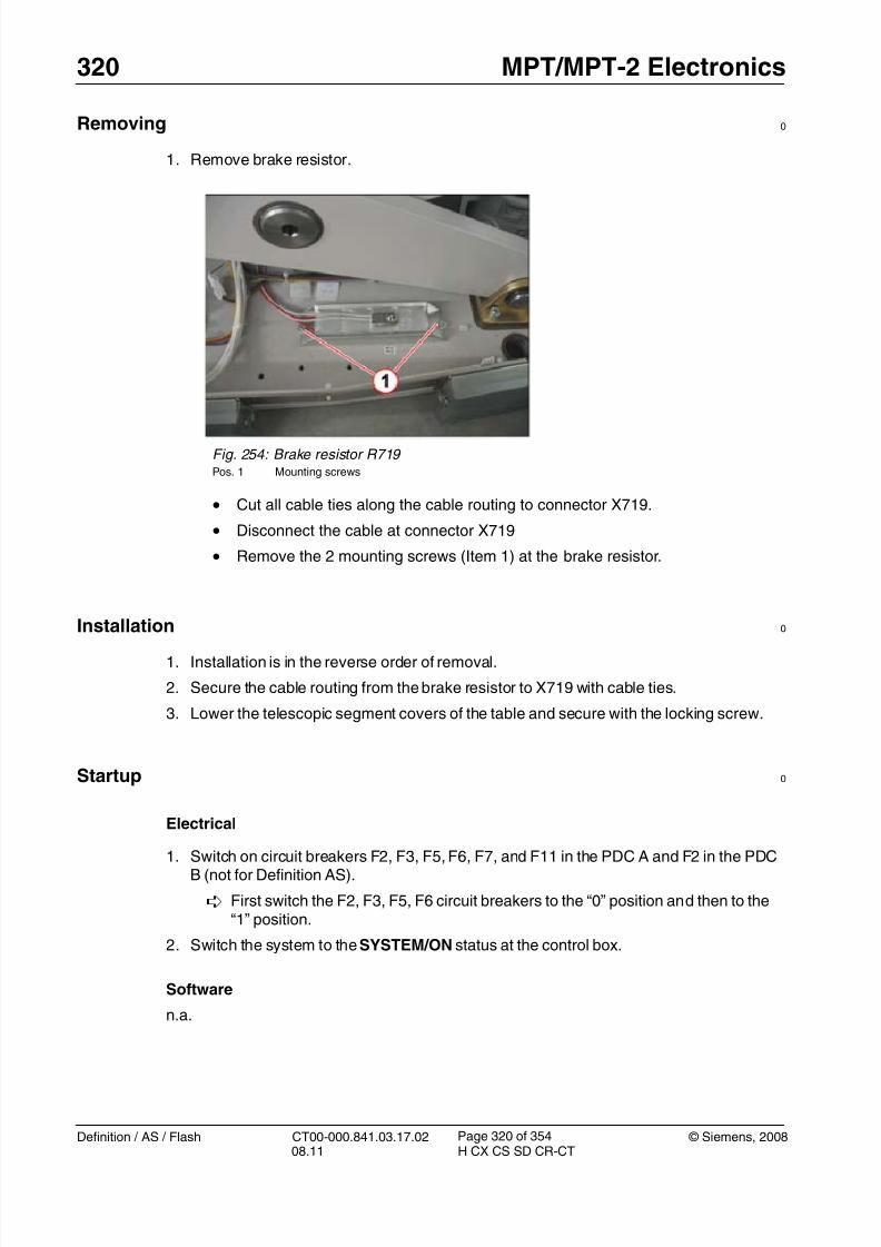
Preliminary steps 0
1. Raise the patient table to maximum height (position 125).
2. Switch system toCOMP/ON at the control box.
3. Switch OFF the gantry/PHS power using service push-button S1 in the PDC.
Secure the circuit breakers that S1 switched OFF against unintended switch-on(e.g. lock and tag).
NOTE Read and observe the safety information in the “Prod-uct-specific safety notes” prior to performing service work on the patient table. If the patient table power is switched offfor service work, always secure it against accidentalswitch-on.
4. Remove the tabletop plate. (Tabletop plate / p. 238)
5. Remove the front-end cover from the left and right side support.(Front and rear covers(left/right) / p. 220)
6. Remove the front tabletop cover (6 plastic caps and Allen screws). (Tabletop covers(front and rear) / p. 209)
7. Remove the left/right rear end covers of the side support (one plastic cap and screweach side).(Front and rear covers (left/right) / p. 220)
8. Feed the tabletop sled towards the gantry to get full access to the rear tabletop cover.9. Remove the rear tabletop cover (6 plastic caps and Allen screws). (Tabletop covers
(front and rear) / p. 209)
Removing 0
1. Move tabletop approx. 1.5 meters into the gantry so that the belt securing point isaccessible from underneath.
2. Release and remove the belt adjuster at the foot end of the tabletop.
- Push the tabletop plate towards the gantry until you achieve a distance of 600 mmbetween the rear pulley and the belt clamp.
- Place the sensor at the center of the trim length over the flat size of the belt (300mm). The distance between sensor and belt should be about 5 to 20 mm.
To learn how to use the tension meter, see the operating instructions delivered withthe meter.
- Start belt vibration by hitting it with the head of a screwdriver.
- Perform the measurement.
- The resonance frequency must be 58 +2 Hz for correct belt tension.
NOTE The value 58 +2 Hz is only valid for a new belt. For othercases, e.g. after replacement of the horizontal motor, the ten-
- PHS top support drive belt, material number 86 14 369
Prerequisites 0
Safety
WARNING [ hz_serdoc_F13G01U12M03 ]
Avoid accident and injury or damage to parts.
Risk of accident and injury!
Read and observe the safety information contained in
the “General” section of this document and/or the“Product specific safety notes”.
Time and Manpower
• 1 person
• Estimated total repair time: 45 min.
Tools and auxiliary equipment
•
Standard service kit• Belt tension meter, for material number see the SPC.
Preliminary steps 0
1. Raise the patient table to maximum height (position 125).
2. Switch system toCOMP/ON at the control box.
3. Switch OFF the gantry/PHS power using service push-button S1 in the PDC.
Secure the circuit breakers that S1 switched OFF against unintended switch-on
(e.g. lock and tag).
NOTE Read and observe the safety information in the “Prod-uct-specific safety notes” prior to performing service work on the patient table. If the patient table power is switched offfor service work, always secure it against accidentalswitch-on.
4. Remove the switchplate cover at the foot end of the tabletop. (Switchplatecover / p. 213)
5. Lower the telescopic covers of the table to the table base. (Telescopic Covers: Lower-
- Pull the top support fully out, away from the gantry. You should achieve a distanceof 435 mm between the rear pulley and the belt clamp.
- The procedure is the same as described in (Installation / p. 100)
Place the sensor at the center of the trim length over the flat size of the belt (seearrow in the figure below). The distance between sensor and belt should be about 5to 20 mm.
To learn how to use the tension meter, see the operating instructions delivered withthe meter.
- Start belt vibration by hitting it with the head of a screwdriver.
- Perform the measurement.
- The resonance frequency must be 75 +2 Hz for correct belt tension.
NOTE The value 75 +2 Hz is only valid for a new belt. For othercases, e.g. after replacement of the horizontal motor, the ten-sion has to be adjusted to 70 +2 Hz.
- PHS top support position sensor, material number 86 14 385
Prerequisites 0
Safety
WARNING [ hz_serdoc_F13G01U12M03 ]
Avoid accident and injury or damage to parts.
Risk of accident and injury!
Read and observe the safety information contained in
the “General” section of this document and/or the“Product specific safety notes”.
Time and Manpower
• 1 person
• Estimated total repair time: 1 hour.
Tools and auxiliary equipment
•
Standard service kit• Feeler gauges e.g., material number 80 38 259
Preliminary steps 0
1. Raise the patient table to maximum height (position 125).
2. Switch system to COMP/ON at the control box.
3. Switch OFF the gantry/PHS power using service push-button S1 in the PDC.
Secure the circuit breakers that S1 switched OFF against unintended switch-on
(e.g. lock and tag).
NOTE Read and observe the safety information in the “Prod-uct-specific safety notes” prior to performing service work on the patient table. If the patient table power is switched offfor service work, always secure it against accidentalswitch-on.
4. Remove the tabletop plate. (Tabletop plate / p. 238)
5. Remove the front end cover from the left and right side support. (Front and rear covers(left/right) / p. 220)
6. Remove the front tabletop cover (6 plastic caps and Allen screws). (Tabletop covers(front and rear) / p. 209)
7. Remove the left/right rear end covers of the side support (one plastic cap and screweach side). (Front and rear covers (left/right) / p. 220)
8. Feed the tabletop sled towards the gantry to get full access to the rear tabletop cover.9. Remove the rear tabletop cover (6 plastic caps and Allen screws). (Tabletop covers
(front and rear) / p. 209)
Removing 0
1. Removing the magnetic sensor:
Fig. 241: MPT: Magnetic sensor (top support position) Pos. 1 Mounting screws
Pos. 2 Cable connection
Pos. 3 Magnetic sensor
• Push the top support all the way towards the gantry.
• Remove the connector from sensor (Item 2).
• Remove 2 mounting nuts (Item 1) and lift off the sensor.
Read and observe the safety information contained in
the “General” section of this document and/or the“Product specific safety notes”.
Time and Manpower
• 1 person
• Estimated total repair time: 1 hr.
Tools and auxiliary equipment
•
Standard service kit
Preliminary steps 0
1. Raise table to maximum vertical position (position 125).
2. Switch system to COMP/ON at the control box.
3. Switch OFF the gantry/PHS power using service push-button S1 in the PDC.
Secure the circuit breakers that S1 switched OFF against unintended switch-on(e.g. lock and tag).
NOTE Read and observe the safety information in the “Prod-uct-specific safety notes” prior to performing service work on the patient table. If the patient table power is switched offfor service work, always secure it against accidentalswitch-on.
4. Raise the telescopic table covers with the adjustable strip (service aid delivered with theMPT) to gain full access to the vertical drive assembly. (Telescopic Covers: Releasing &Raising / p. 224)
The Auto_Complete is started and checks which adjustments are required.
Follow the instructions of the Auto_Complete routine.
Tests
1. Check the vertical table movement via the buttons at the gantry control panels andcheck the display for the vertical position at the gantry display.
Read and observe the safety information contained in
the “General” section of this document and/or the“Product specific safety notes”.
Time and Manpower
• 1 person
• Estimated total repair time: 1 hr.
Tools and auxiliary equipment
•
Standard service kit
Preliminary steps 0
1. Raise table to maximum vertical position (position 125).
2. Switch system toCOMP/ON at the control box.
3. Switch OFF the gantry/PHS power using service push-button S1 in the PDC.
Secure the circuit breakers that S1 switched OFF against unintended switch-on(e.g. lock and tag).
NOTE Read and observe the safety information in the “Prod-uct-specific safety notes” prior to performing service work on the patient table. If the patient table power is switched offfor service work, always secure it against accidentalswitch-on.
4. Raise the telescopic table covers with the adjustable strip (service aid delivered with theMPT) to gain full access to the vertical drive assembly. (Telescopic Covers: Releasing &Raising / p. 224)
• The safety nut switch (Item 2) monitors the internal safety nut. It is nota field replaceable unit. Should the nut fail, the machine groove (item1) will drop into the casing and the switch will operate.
If the machine groove is not visible, the complete vertical driveassembly should be replaced.
• In normal operation when using the gantry controls, the software lim-its the vertical movement to 10 mm before the mechanical limit; how-ever, this position is referenced to the floor and can be affected byshimming. Therefore, the microswitches are adjusted to operate 5mm before the mechanical limit. Using the service movement
switches will allow the table to raise or lower until the microswitchoperates.
• Turn on F7 and raise the table using the Service controls (Servicemovement of PHS / p. 21) to a position just before the mechanicallimit.
Do not drive to the mechanical limit.
• Turn off F7.
• Use a 6 mm hex key in the manual lift screw (Vertical drive / p. 79) and move the table to the mechanical limit. Measure the table heightfrom the floor and note it.
• Move the table height to a position 5 mm away from the mechanicallimit.
• Adjust the microswitch by releasing the adjuster nut (Item 1) and slid-ing the carrier so that it operates at this point; use the service move-ment switches to check the final position.
- PHS power supplies, material number 86 14 500 (for MPT and MPT-2) and 86 18113 (for MPT-2)
Prerequisites 0
Safety
WARNING [ hz_serdoc_F13G01U12M03 ]
Avoid accident and injury or damage to parts.
Risk of accident and injury!
Read and observe the safety information contained inthe “General” section of this document and/or the“Product specific safety notes”.
Time and manpower
• 1 person
• Estimated total repair time: 30 min
Tools and Auxiliary Equipment
• Standard service kit
Preliminary steps 0
1. If possible, raise the patient table to maximum height (position 125).
2. Switch system to COMP/ON at the control box.
3. Switch OFF the gantry/PHS power using service push-button S1 in the PDC.
Secure the circuit breakers that S1 switched OFF against unintended switch-on
(e.g. lock and tag).
NOTE Read and observe the safety information in the “Prod-uct-specific safety notes” prior to performing service work on the patient table. If the patient table power is switched offfor service work, always secure it against accidentalswitch-on.
4. Raise the telescopic segment covers with the adjustable strip (service aid deliveredwith MPT) to gain full access to the electronics assembly. (Telescopic Covers: Lower-ing & Removing / p. 228)
5. Remove the foot switch assembly at the left table base for better access (3 Allenscrews).
- Relay (K711), material number 86 14 476- Contactor relay (K701), material number 86 14 468
- Rectifier (V702), material number 86 14 492
Prerequisites 0
Safety
WARNING [ hz_serdoc_F13G01U12M03 ]
Avoid accident and injury or damage to parts.
Risk of accident and injury!
Read and observe the safety information contained inthe “General” section of this document and/or the“Product specific safety notes”.
Time and manpower
• 1 person
• Estimated total repair time: 30 min. per item.
Tools and Auxiliary Equipment
• Standard service kit
Preliminary steps 0
1. If possible, raise the patient table to maximum height (position 125).
2. Switch system toCOMP/ON at the control box.
3. Switch OFF the gantry/PHS power using service push-button S1 in the PDC. Secure the circuit breakers that S1 switched OFF against unintended switch-on
(e.g. lock and tag).
NOTE Read and observe the safety information in the “Prod-uct-specific safety notes” prior to performing service work on the patient table. If the patient table power is switched offfor service work, always secure it against accidentalswitch-on.
4. Raise the telescopic segment covers with the adjustable strip (service aid deliveredwith MPT) to gain full access to the electronics assembly. (Telescopic Covers: Releas-ing & Raising / p. 224)
Removing 0
1. Removing parts
Fig. 251: Location of relays, fuses, and rectifier Pos. 1 Contactor/safety relay K701
Pos. 2 Fuses F701/F711/F721/F731 (4 x 1AT)
Pos. 3 Relay K711 (vertical brake)
Pos. 4 Rectifier V702
Pos. 5 Mounting rail
Pos. 6 Rail clamp
Pos. 7 Relay K709 (location behind K701)
• Remove wires, check that the markings are clear and understand-
able.
• Safety relay K701 (Item 1), relay K709 (item 7) and K711 verticalbrake relay (item 3) are all released by removing the rail clamp (item6) on the respective mounting rail (item 5).
• The rectifier (Item 4) is secured by a a single central mounting screw.
Read and observe the safety information contained in
the “General” section of this document and/or the“Product specific safety notes”.
Time and manpower
• 1 person
• Estimated total repair time: 20 min.
Tools and Auxiliary Equipment
•
Standard service kit
Preliminary steps 0
1. If possible, raise the patient table to maximum height (position 125).
2. Switch system to COMP/ON at the control box.
3. Switch OFF the gantry/PHS power using service push-button S1 in the PDC.
Secure the circuit breakers that S1 switched OFF against unintended switch-on(e.g. lock and tag).
NOTE Read and observe the safety information in the “Prod-uct-specific safety notes” prior to performing service work on the patient table. If the patient table power is switched offfor service work, always secure it against accidentalswitch-on.
4. Raise the telescopic segment covers with the adjustable strip (service aid deliveredwith MPT) to gain full access to the electronics assembly. (Telescopic Covers: Releas-ing & Raising / p. 224)
NOTE Read and observe the safety information in the “Prod-uct-specific safety notes” prior to performing service work on the patient table. If the patient table power is switched offfor service work, always secure it against accidental
switch-on.
4. Raise the telescopic segment covers with the adjustable strip (service aid deliveredwith MPT) to gain full access to the electronics assembly. (Telescopic Covers: Releas-ing & Raising / p. 224)
Removing 0
1. Remove the table master board (LMAS-2 or LMAS-3).
NOTE The figure below shows the LMAS-2 board as an example.
The attachment points of the LMAS-3 are identical.
Installation 0
1. Connect all lower cables to the new LMAS assembly.
T 2. Mount the LMAS assembly to the frame with the 2 nuts and tighten to 3 Nm.
3. Reestablish all other cable connections at the LMAS.
4. Lower the telescopic segment covers of the table and secure with the locking screw.
Read and observe the safety information contained in
the “General” section of this document and/or the“Product specific safety notes”.
Time and manpower
• 1 person
• Estimated total repair time: 30 min.
Tools and Auxiliary Equipment
•
Standard service kit
Preliminary steps 0
1. If possible, raise the patient table to maximum height (position 125).
2. Switch system to COMP/ON at the control box.
3. Switch OFF the gantry/PHS power using service push-button S1 in the PDC.
Secure the circuit breakers that S1 switched OFF against unintended switch-on(e.g. lock and tag).
NOTE Read and observe the safety information in the “Prod-uct-specific safety notes” prior to performing service work on the patient table. If the patient table power is switched offfor service work, always secure it against accidentalswitch-on.
4. Raise the telescopic segment covers with the adjustable strip (service aid deliveredwith MPT) to gain full access to the electronics assembly. (Telescopic Covers: Releas-ing & Raising / p. 224)
- Vertical motor controller LUST, material number 86 14 518
NOTE Do not replace LMAS and motor controllers at the same time!
If you are uncertain which component is causing the prob-lem, finish replacing one part before you replace the next.
Prerequisites 0
Safety
WARNING [ hz_serdoc_F13G01U12M03 ]
Avoid accident and injury or damage to parts.
Risk of accident and injury!
Read and observe the safety information contained inthe “General” section of this document and/or the“Product specific safety notes”.
Time and manpower
• 1 person
• Estimated total repair time: 45 min.
Tools and Auxiliary Equipment
• Standard service kit
Preliminary steps 0
1. If possible, raise the patient table to maximum height (position 125).2. Switch system toCOMP/ON at the control box.
3. Switch OFF the gantry/PHS power using service push-button S1 in the PDC.
Secure the circuit breakers that S1 switched OFF against unintended switch-on(e.g. lock and tag).
NOTE Read and observe the safety information in the “Prod-uct-specific safety notes” prior to performing service work on the patient table. If the patient table power is switched offfor service work, always secure it against accidental
4. Raise the telescopic segment covers with the adjustable strip (service aid deliveredwith MPT) to gain full access to the electronics assembly. (Telescopic Covers: Releas-ing & Raising / p. 224)
Removing 0
1. Remove the vertical motor controller.
Installation 0
1. Check the switch S3 on the inverter and set switch to Pos.1.
S3 must be in Pos.1
2. Install the new motor controller and secure with the two mounting screws.
T Tighten screws to 3 Nm.
3. Connect all cables at the motor controller.
4. Reinstall the patient table segment covers.
Startup 0
Electrical
1. Switch on circuit breakers F2, F3, F5, F6, F7, and F11 in the PDC A and F2 in the PDCB (not for Definition AS).
First switch the F2, F3, F5, F6 circuit breakers to the “0” position and then to the“1” position.
Fig. 255: Vertical motor controller (LUST) Pos. 1 Mounting screws
Horizontal motor controller U731 (Tabletop) / U721 (Top Support)9.7
• The following instructions are applicable to:
- Horizontal motor controller, material number 86 14 401
NOTE Do not replace LMAS and motor controllers at the same time!
If you are uncertain which component is causing the prob-lem, finish replacing one part before you replace the next.
Prerequisites 0
Safety
WARNING [ hz_serdoc_F13G01U12M03 ]
Avoid accident and injury or damage to parts.
Risk of accident and injury!
Read and observe the safety information contained inthe “General” section of this document and/or the“Product specific safety notes”.
Time and manpower
• 1 person
• Estimated total repair time: 45 min.
Tools and Auxiliary Equipment
• Standard service kit
Preliminary steps 0
1. If possible, raise the patient table to maximum height (position 125).2. Switch system to COMP/ON at the control box.
3. Switch OFF the gantry/PHS power using service push-button S1 in the PDC.
Secure the circuit breakers that S1 switched OFF against unintended switch-on(e.g. lock and tag).
NOTE Read and observe the safety information in the “Prod-uct-specific safety notes” prior to performing service work on the patient table. If the patient table power is switched offfor service work, always secure it against accidental
Read and observe the safety information contained in
the “General” section of this document and/or the“Product specific safety notes”.
Time and manpower
• 1 person
• Estimated total repair time: 45 min.
Tools and auxiliary equipment
•
Standard service kit
Preliminary steps 0
1. Lower the telescopic covers as described in (Side support (left/right) / p. 217)
2. Switch system toCOMP/ON at the control box.
3. Switch OFF the gantry/PHS power using service push-button S1 in the PDC.
Secure the circuit breakers that S1 switched OFF against unintended switch-on(e.g. lock and tag).
NOTE Read and observe the safety information in the “Prod-uct-specific safety notes” prior to performing service work on the patient table. If the patient table power is switched offfor service work, always secure it against accidentalswitch-on.
NOTE The PMM box is fully integrated in the tabletop handleassembly.
Therefore the complete assembly must be replaced.
Prerequisites 0
Safety
WARNING [ hz_serdoc_F13G01U12M03 ]
Avoid accident and injury or damage to parts.
Risk of accident and injury!
Read and observe the safety information contained inthe “General” section of this document and/or the“Product specific safety notes”.
Time and manpower
• 1 person• Estimated total repair time: 15 min.
Tools and Auxiliary Equipment
• Standard service kit
Preliminary steps 0
1. Raise the patient table to height of 125.
2. Shut down the system software (click <SYSTEM> and select <END> in the user mainmenu).
3. Click Shutdown System
4. Confirm with Yes in the dialog box displayed.
NOTE Read and observe the safety information in the “Prod-uct-specific safety notes” prior to performing service work on the patient table. If the patient table power is switched offfor service work, always secure it against accidentalswitch-on.
NOTE On PMMs with revision level 02 and higher, the CanOpen ter-
minator is installed in the module. Therefore, the externalresistor in plug X2 is no longer required.
Do not install plug X2!
Startup 0
Electrical
1. Press the Sys On key on the control box. The whole system is ready for operation whenthe Sys On LED is lit and the operating elements on the control box are backlit.
Software
1. If the system shows a fatal firmware mismatch, the new firmware has to be installed:
Go to Local Service > Control > Firmware to load the current firmware version.
Tune-up
n.a.
Tests
1. Activate the ECG Monitor Demo mode
- Select: Control > Configuration
- Select: Heartview
- Mark checkbox “ECG Monitor Demo mode”
- Press <Apply>
An ECG pulse must be seen at the gantry display.
2. Deactivate the ECG Monitor Demo mode by deselecting the checkbox in the Heartview
This chapter describes the replacement of the following components of the InterventionModule (IVM).
• Intervention Panel (IVP) with accumulator pack
• Wireless Interface Gantry (WIG). This item is located in the right gantry stand.
• Rechargeable batteries of IVP (4 x AA type)
Fig. 262: Components of Intervention Module (IVM)
Pos. 1 Intervention Panel (IVP)
Pos. 2 Wireless Interface Gantry (WIG)
Pos. 3 IVP battery pack (4 x rechargeable AA type)
NOTE The replacement of cables that belong to the IVM option isnot described in this document. For further installation infor-mation, refer to the “Options - Installation and Startup -Patient Table/Intervention Options” document, print numberCT00-000.841.26.xx.02.
If the USB FOC cable needs replacing, follow the guidelinesfor optical cables, e.g. minimum bending radius is 60 mm(approx. 2.4 ").
- Intervention Panel, material number 101 61 670 (1/ Fig. 262 / p. 334)
Prerequisites 0
Safety
WARNING [ hz_serdoc_F13G01U12M03 ]
Avoid accident and injury or damage to parts.
Risk of accident and injury!
Read and observe the safety information contained in
the “General” section of this document and/or the“Product specific safety notes”.
Time and manpower
• 1 person
• Estimated total repair time: 30 min
Tools and Auxiliary Equipment
•
Standard service kit• Torx key (size: TX8)
Preliminary steps 0
1. Switch system to COMP/ON at the control box.
2. Switch OFF the gantry/PHS power using service push-button S1 in the PDC.
Secure the circuit breakers that S1 switched OFF against unintended switch-on(e.g. lock and tag).
NOTE Read and observe the safety information in the “Prod-uct-specific safety notes” prior to performing service work on the patient table. If the patient table power is switched offfor service work, always secure it against accidentalswitch-on.
1. Install the new rechargeable batteries and set the “Wireless” switch at the new IVP.
2. Set the “Wireless mode”
- Set the “Wireless” switch (pos. 5) to Position “ON”
3. Reinstall the cover at the IVP (pos. 3)
4. Install the country-specific IVP approval label (2-6/ Fig. 266 / p. 339) at the IVP housingaccording to Figure: (4/ Fig. 265 / p. 338)
Fig. 264: IVP (rear) Pos. 1 Release button
Pos. 2 Cable connector
Pos. 3 Cover
Pos. 4 Rechargeable batteries (4 x AA type)
Pos. 5 Wireless operation switch
• Remove the cover (Pos.3) from the new IVP (5 Torx screws)
• Install the 4 batteries (pos.4), which are delivered with the new sparepart, according to the polarity symbols in the battery compartment.
Due to warranty reasons, use only the accumulator pack, whichis delivered with the spare part. Other batteries may change thewarranted standby time or will even damage the IVP.
NOTE This labelling procedure is only relevant for wireless oper-ated IVP modules and for the following countries: China,Singapore, Australia, New Zealand and Japan
A country-specific IVP approval label must be installed at theIVP housing after replacement.
NOTE For wireless operating Intervention Module ONLY!
After replacement of the component IVP and/or WIG, a“teaching” procedure for synchronizing the wireless commu-
nication is necessary.
This “teaching” procedure must be executed in servicemode.
The IVP and WIG have to be set to wireless mode AND thecable MUST be connected.
• Execute the teaching procedure to synchronize the wireless communication betweenthe components IVP and WIG.
Make sure for the wireless module the cable is connected and both switches are set to“wireless mode”, on WIP and on the IVP. The “wireless” switch for the IVP is located
behind the rear cover of the IVP, next to the batteries.
- Wireless Interface Gantry, material number 101 61 671 (2/ Fig. 262 / p. 334)
• The WIG is located in the right gantry stand.
Prerequisites 0
Safety
WARNING [ hz_serdoc_F13G01U12M03 ]
Avoid accident and injury or damage to parts.
Risk of accident and injury!
Read and observe the safety information contained inthe “General” section of this document and/or the“Product specific safety notes”.
Time and manpower
• 1 person
• Estimated total repair time: 30 min
Tools and Auxiliary Equipment• Standard service kit
Preliminary steps 0
1. Switch system to COMP/ON at the control box.
2. Switch OFF the gantry/PHS power using service push-button S1 in the PDC.
Secure the circuit breakers that S1 switched OFF against unintended switch-on(e.g. lock and tag).
NOTE Read and observe the safety information in the “Prod-uct-specific safety notes” prior to performing service work on the patient table. If the patient table power is switched offfor service work, always secure it against accidentalswitch-on.
3. Remove the right side cover at the right gantry stand.
4. Remove the front right cover at the right gantry stand.
- Rechargeable batteries of IVP, material number 101 61 762 (contains a set of 4 bat-teries) (3/ Fig. 262 / p. 334)
NOTE Due to warranty reasons, use only the accumulator pack named above. Other batteries may change the warranty timeor will even damage the IVP.
Prerequisites 0
Safety
WARNING [ hz_serdoc_F13G01U12M03 ]
Avoid accident and injury or damage to parts.
Risk of accident and injury!
Read and observe the safety information contained inthe “General” section of this document and/or the“Product specific safety notes”.
Time and manpower
• 1 person
• Estimated total repair time: 15 min
Tools and Auxiliary Equipment
• Standard service kit
• Torx key (size: TX8)
Preliminary steps 0
1. Switch system toCOMP/ON at the control box.
2. Switch OFF the gantry/PHS power using service push-button S1 in the PDC.
Secure the circuit breakers that S1 switched OFF against unintended switch-on(e.g. lock and tag).
NOTE Read and observe the safety information in the “Prod-uct-specific safety notes” prior to performing service work on the patient table. If the patient table power is switched offfor service work, always secure it against accidentalswitch-on.