Page 1
Title: Challenges in Structural Design of Bumeo W-project
Authors: Jong Soo Kim, CS Structural EngineeringDuck Won Jo, CS Structural EngineeringEun Gyu Choi, CS Structural Engineering
Subjects: Building Case StudyCivil Engineering
Keywords: ConcreteCoreFoundationOutriggersSeismicWind
Publication Date: 2020
Original Publication: International Journal of High-Rise Buildings Volume 9 Number 2
Paper Type: 1. Book chapter/Part chapter2. Journal paper3. Conference proceeding4. Unpublished conference paper5. Magazine article6. Unpublished
© Council on Tall Buildings and Urban Habitat / Jong Soo Kim; Duck Won Jo; Eun Gyu Choi
ctbuh.org/papers
Page 2
International Journal of High-Rise Buildings
June 2020, Vol 9, No 2, 167-173
https://doi.org/10.21022/IJHRB.2020.9.2.167
International Journal of
High-Rise Buildingswww.ctbuh-korea.org/ijhrb/index.php
Challenges in Structural Design of Bumeo W-project
Jong Soo Kim†, Duck Won Jo, and Eun Gyu Choi
CS Structural Engineering, Seoul, Korea
Abstract
W-Project is 60-story mixed-use residential building complex project in Daegu, the third biggest city in South Korea. There are lots explorable items to be solved to secure structural safety and meet the serviceability requirements. This paper describes what kind of structural system is optimized based on the architectural requirements and structural components design and the grade of concrete strength altered on floors. The defining process of lateral resisting system of outrigger compared to the core ratio of typical plan is illustrated in detail.
Keywords: High-rise Building, Lateral Load System, Outngger System, Coupling Beam, Interaction Force
1. Introduction
W-Project is the multi-complex with four units of 60-
story building. South Korea is not categorized as a strong
seismic zone, but it is located in the middle of seismic
zone and in the passage of typhoon from Pacific Ocean.
In this paper, structural system for residential high-rise
building is addressed considering architectural requirements
and construction cost.
2. Material Strength
Using higher strength material could make structural
members slender and it can improve the axial capacity of
vertical members. The feasibility studies are conducted in
terms of various combinations of material strength. We
considered whether if the high strength materials could be
supplied instantly on the site as ordered by constructor for
the specific area. Therefore, the concrete strength is used
up to 60 MPa and the rebar strength is used up to
600 MPa. Fig. 2 shows concrete strength of 28 days at
each floor zone.
†Corresponding author: Jong Soo Kim
Tel: +82-2-3497-7800
E-mail: [email protected]
Figure 1. Bird’s Eye View.
Table 1. Summary of W-Project
ProjectW-Project
(Daegu Bumeo Mixed-Use Development Project)
Location Daegu, South Korea
Occupancy Residential Complex
Size GFA: 330,612 m2, B4/60F
Height 190.65 m
Figure 2. Tower Structural System and Concrete Strength of Vertical and Horizontal Members.
Page 3
168 Jong Soo Kim et al. | International Journal of High-Rise Buildings
3. Gravity Load System
To choose gravity load resisting system for high-rise
buildings, the floor height is the first consideration in
some issues. Flat Plate Slab system is chosen to reduce
the story height and for constructability, however it gives
less lateral stiffness to the structure. For W-Project,
thickness 250 mm of Flat Plate Slab system is applied
and shear reinforcing bars are added to resist punching
shear around the columns. Fig. 3 shows the Flat Plate
Slab of the typical floor.
RC Beam & Girder and Flat Plate Slab Systems are
selected for the gravity load resisting of podium area. The
direct cost of RC Beam & Girder System is slightly
higher than Flat Slab System. Besides construction cost,
Flat Slab System reduces the floor height. To reduce the
floor height of basement can save excavation cost of
basement area consisting mostly hard rock strata. It is a
summary of structural systems for W-Project as below.
The basement floors are designed by 250 mm thickness
flat slab with drops around column zone as shown on Fig. 4.
4. Lateral Load System
4.1. The Selection of Lateral Load Resisting System
The lateral stiffness and characteristic are evaluated
through four steps by structural system and members.
1) Core wall only
2) Core wall with reinforced coupled beam
3) Core wall with coupled beam, outrigger and belt wall
4) Core wall with coupled beam, outrigger and belt
wall plus adopting the out of plane stiffness of typical
floor slab
The natural period of core wall only is 8.21 seconds
and the result stiffness of reinforced coupled beams is
assumed by 50 percentage cracked section. The effective
stiffness of flat slab is counted by 20 percentage for cracked
section. Fig. 5 reveals what extend of the effectiveness to
resisting lateral loads according to four steps of structural
system is.
Figure 4. Flat Plate Slab of Basement Floor.
Table 2. Structural System
Tower Lateral System RC Core Wall + Outrigger + Belt Wall
Tower Gravity System Flat Plate System (THK. 250 mm)
Podium Gravity Sys-tem
RC Beam & Girder System, Flat Slab System
Figure 3. Flat Plate Slab of Typical Floor.
Figure 5. Lateral Stiffness Increment by Structural Elements.
Page 4
Challenges in Structural Design of Bumeo W-project 169
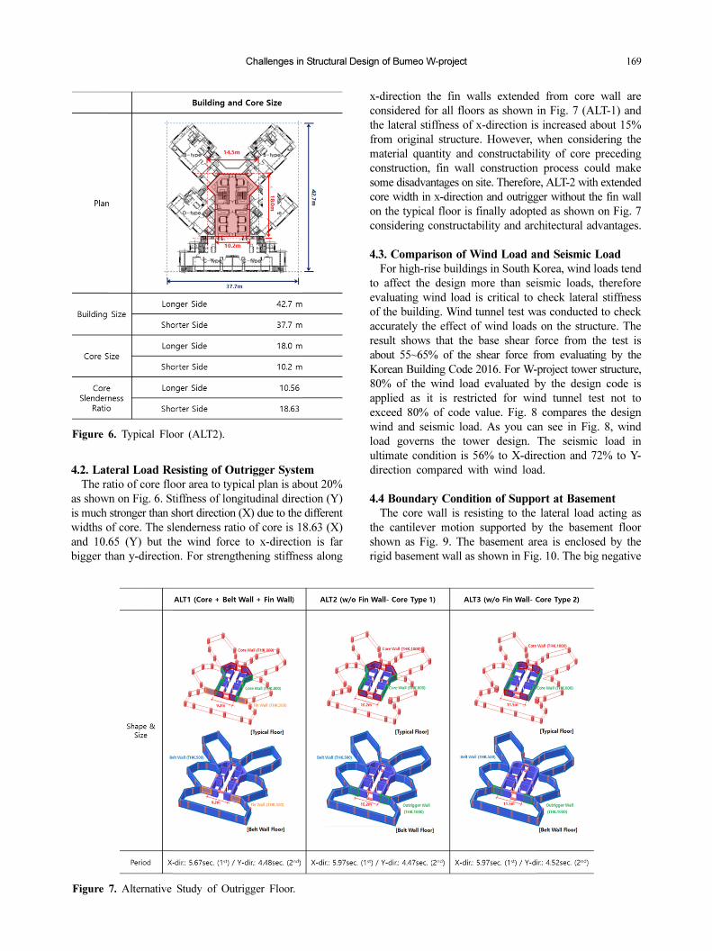
4.2. Lateral Load Resisting of Outrigger System
The ratio of core floor area to typical plan is about 20%
as shown on Fig. 6. Stiffness of longitudinal direction (Y)
is much stronger than short direction (X) due to the different
widths of core. The slenderness ratio of core is 18.63 (X)
and 10.65 (Y) but the wind force to x-direction is far
bigger than y-direction. For strengthening stiffness along
x-direction the fin walls extended from core wall are
considered for all floors as shown in Fig. 7 (ALT-1) and
the lateral stiffness of x-direction is increased about 15%
from original structure. However, when considering the
material quantity and constructability of core preceding
construction, fin wall construction process could make
some disadvantages on site. Therefore, ALT-2 with extended
core width in x-direction and outrigger without the fin wall
on the typical floor is finally adopted as shown on Fig. 7
considering constructability and architectural advantages.
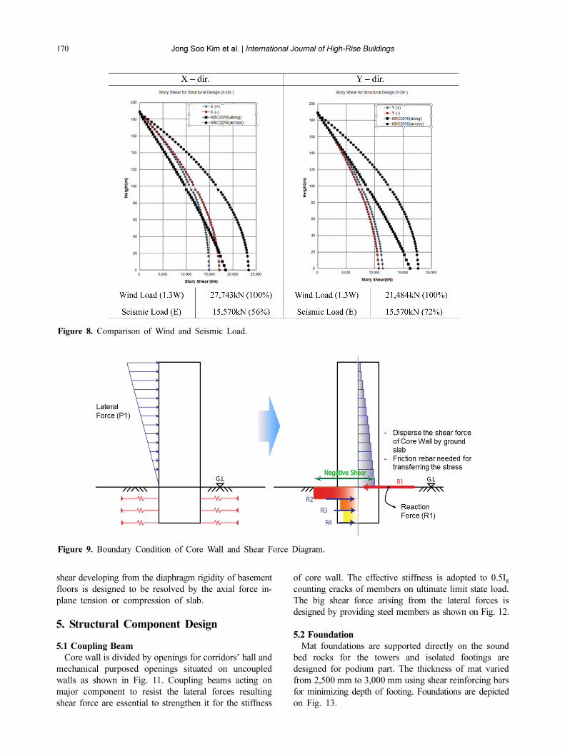
4.3. Comparison of Wind Load and Seismic Load
For high-rise buildings in South Korea, wind loads tend
to affect the design more than seismic loads, therefore
evaluating wind load is critical to check lateral stiffness
of the building. Wind tunnel test was conducted to check
accurately the effect of wind loads on the structure. The
result shows that the base shear force from the test is
about 55~65% of the shear force from evaluating by the
Korean Building Code 2016. For W-project tower structure,
80% of the wind load evaluated by the design code is
applied as it is restricted for wind tunnel test not to
exceed 80% of code value. Fig. 8 compares the design
wind and seismic load. As you can see in Fig. 8, wind
load governs the tower design. The seismic load in
ultimate condition is 56% to X-direction and 72% to Y-
direction compared with wind load.
4.4 Boundary Condition of Support at Basement
The core wall is resisting to the lateral load acting as
the cantilever motion supported by the basement floor
shown as Fig. 9. The basement area is enclosed by the
rigid basement wall as shown in Fig. 10. The big negative
Figure 6. Typical Floor (ALT2).
Figure 7. Alternative Study of Outrigger Floor.
Page 5
170 Jong Soo Kim et al. | International Journal of High-Rise Buildings
shear developing from the diaphragm rigidity of basement
floors is designed to be resolved by the axial force in-
plane tension or compression of slab.
5. Structural Component Design
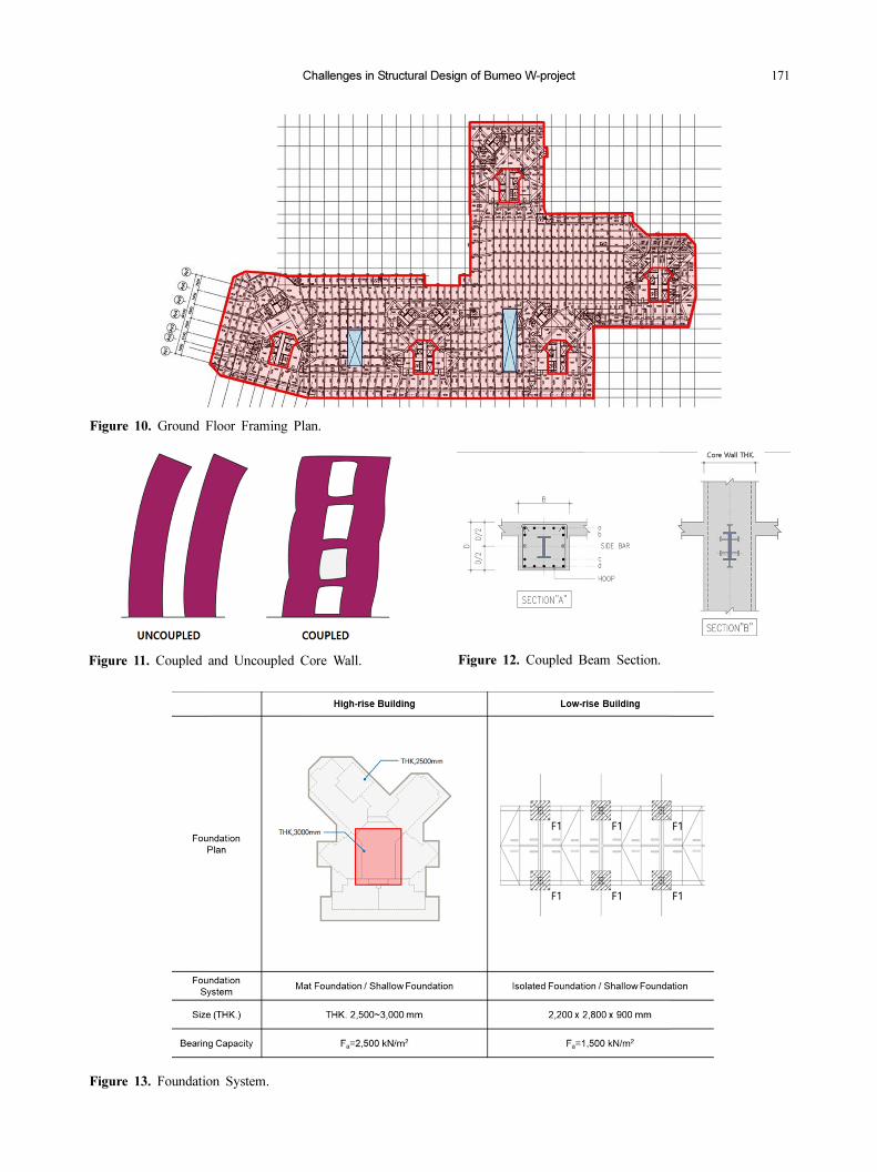
5.1 Coupling Beam
Core wall is divided by openings for corridors’ hall and
mechanical purposed openings situated on uncoupled
walls as shown in Fig. 11. Coupling beams acting on
major component to resist the lateral forces resulting
shear force are essential to strengthen it for the stiffness
of core wall. The effective stiffness is adopted to 0.5Igcounting cracks of members on ultimate limit state load.
The big shear force arising from the lateral forces is
designed by providing steel members as shown on Fig. 12.
5.2 Foundation
Mat foundations are supported directly on the sound
bed rocks for the towers and isolated footings are
designed for podium part. The thickness of mat varied
from 2,500 mm to 3,000 mm using shear reinforcing bars
for minimizing depth of footing. Foundations are depicted
on Fig. 13.
Figure 8. Comparison of Wind and Seismic Load.
Figure 9. Boundary Condition of Core Wall and Shear Force Diagram.
Page 6
Challenges in Structural Design of Bumeo W-project 171
Figure 10. Ground Floor Framing Plan.
Figure 11. Coupled and Uncoupled Core Wall. Figure 12. Coupled Beam Section.
Figure 13. Foundation System.
Page 7
172 Jong Soo Kim et al. | International Journal of High-Rise Buildings
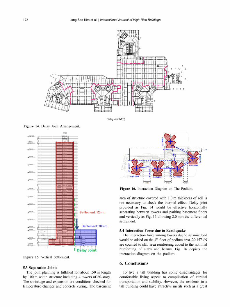
5.3 Separation Joints
The joint planning is fulfilled for about 150 m length
by 100 m width structure including 4 towers of 60-story.
The shrinkage and expansion are conditions checked for
temperature changes and concrete curing. The basement
area of structure covered with 1.0 m thickness of soil is
not necessary to check the thermal effect. Delay joint
provided as Fig. 14 would be effective horizontally
separating between towers and parking basement floors
and vertically as Fig. 15 allowing 2.0 mm the differential
settlement.
5.4 Interaction Force due to Earthquake
The interaction force among towers due to seismic load
would be added on the 4th floor of podium area. 20,157 kN
are counted to slab area reinforcing added to the nominal
reinforcing of slabs and beams. Fig. 16 depicts the
interaction diagram on the podium.
6. Conclusions
To live a tall building has some disadvantages for
comfortable living aspect to complication of vertical
transportation and stability. However, the residents in a
tall building could have attractive merits such as a great
Figure 14. Delay Joint Arrangement.
Figure 15. Vertical Settlement.
Figure 16. Interaction Diagram on The Podium.
Page 8
Challenges in Structural Design of Bumeo W-project 173
view and convenient facilities even though they have
some disadvantages. For this reason, high-rise structures
are expected to be expanded in the future considering to
population density of South Korea.
The legislation caused by earthquakes that occurred in
recent years on the southern part of Korea peninsular is
intensifying to secure the stability to structures. Engineers
are having their best to develop its proper structure system to
cover requirements from architects and developers. It is
anticipating that the articles from material to how define
structural system are helpful further to encourage the
better structural solutions.
References
The law of building structural design standard (2017).
Ministry of Land, Infrastructure, and Transport.
Korean Design Standard (2016). Ministry of Land,
Infrastructure, and Transport.
Korea Building Code (2016). AIK.
Concrete Design Code (2012). KCI.
Steel Structure Design Code (2016), Ministry of Land,
Infrastructure, and Transport.
Steel-Reinforced Concrete Structure Design Standard and
Commentary (2000). AIK.
Moon, K. (2016). Outrigger System for Structural Design of
Complex-Shaped Tall Buildings. International Journal of
High-Rise Buildings, 5(1), 13-20.
Hyun-hee Ryu, Jong-soo Kim, Eun-gyu Choi, and Sang-
hoon Lee (2017). Preliminary Design of Structural Health
Monitoring for High-Rise Buildings. International Journal
of High-Rise Buildings, 6(3), 279-284.
Hong-Gun Park, Hyeon-Jin Kim, and Jin-Young Park
(2019). Corner Steel plate-Reinforces Core Wall System.
International Journal of High-Rise Buildings, 8(3), 193-
199.