Studies on Serviceability of ConcreteStructures under Static and Dynamic Loads
Ding Dajun and An LinNanjing Institute of Technology, Nanjing, China
ABSTRACT
This paper presents a series of experimental andtheoretical studies on the serviceability of concretestructures, conducted at Nanjing Institute of Tech-nology (NIT) for more than 35 years. They includestudies of cracking and deformations of concretemembers under static loading and of deforma-tions under dynamic loading. For crack widthsand deformations under static loading, the firstauthor has suggested a unified calculation pro-cedure based on a larger number of experimen-tal studies, which includes the members subjectedto flexure under short- and long-term loading andunder eccentric tensile or compressive forces. Morethan 700 specimens were tested. Most of thecalculation procedures suggested have beenadopted in relevant Chinese design codes andspecifications. For the deformations under dynamicseismic and wind actions, the 318m high NanjingTV Tower was chosen as the case study.
INTRODUCTION
The structural design codes current in most coun-tries prescribe that two limit states should be con-sidered for concrete structures, i.e., ultimate limitstate and serviceability limit state. The CEB-FIPModel Code (published in 1993) classifies theserviceability limit state into three categories: 1)limit state of cracking and excessive compression,2) limit state of deformations, and 3) limitation ofvibrations.
The Chinese Design Code of Concrete Structures,GBJ10-89, classifies beams of different types(e.g., floor beam, roof beam, crane beam, etc.)according to their circumstantial conditions (suchas normal room temperatures, outdoor or indoorconditions, or very humid conditions) in whichthese members are placed for service. Thus there
are three levels (I, II, and III) of controlling crack-ing. Reinforced concrete (RC) members belongto level III because they cannot be guaranteednot to crack and maximum crack widths could notbe limited to a maximum of 0.2, 0.3, and 0.4mmaccording to different cases of exposure. Pre-stressed concrete (PC) members may belong tolevel II or III for pre-stressing cold-tensioned steelbars, and to level I or II for high strength wires.The members of level I should be strictly precludedfrom crack formation and are not permitted toproduce tensile stress in concrete on their tensileface under the combination of the effects of short-term actions. The members of level II should begenerally precluded from crack formation and arenot permitted to produce tensile stress in concreteon their tensile face under the combination of theeffects of long-term actions. Members of level IIare permitted to produce tensile stress ctσ undershort-term actions but ctσ should not be larger than
ctσ tkfγ , where ctα is a limitation factor of tensilestress in concrete and is equal to 0.3, 0.5 or 1.0.In this case, γ is a factor representing the influ-ence of plastic deformation in tensile concretedepending on the section shape, determined fromthe assumption of plane section hypothesis ofbeam theory and the tensile edge strain equal to
ctk Ef /2 as well as the tensile stress diagram on arectangular section, as given in the Design CodeGBJ10-89 (e.g., γ =1.75 for rectangular and T-sections, whereas the values for γ are generallysmaller than 1.75 for, inverted T- and I-sections,and tkf is the characteristic tensile strength ofconcrete).
For calculating the deflections of simply supportedmembers, the Chinese Design Code prescribesusing the principle of minimal stiffness (i.e., thatof a cracked section with Mmax), for the lengthsnear the support in a beam under uniform load-
CTBUH REVIEW/VOLUME 1, NO. 2: FEBRUARY 2001 58
ing or for the shear-span in a beam under con-centrated loads though the stiffness is larger thanthat at mid-span. Minimal stiffness is determinedby evaluating bending along normal sections.However, the increased influence of tensile steelstrains due to the bending along diagonal sec-tions and the influence of shear deformationsshould also be considered, so the above prin-ciple can be adopted along the entire beamlength (Ding, et. al., 1986). For calculating thedeflections of a continuous beam, the respectiveminimal stiffness along the lengths with maximumpositive and negative moments should be used(Ding, 1989 and 1990).
For considering the redistribution of internalforces in continuous beams under service load-ing, with two fixed ends (for middle span) andone fixed end and one simply supported end (forend span), the first author suggested adjustmentfactors µ for the support moments (Ding, 1989and 1990). In determining µ , the shift of inflec-tion points after the adjustments of the support
moment was considered, so the proposed valuesare more precise as compared with the values oftests in China and elsewhere, including the testsconducted at NIT in which the diagrams for de-flection factors of continuous beams were given(Ding, 1989).
The allowable deflections [f] of flexural memberslisted in the Chinese Code, depending on span( ), are given as <7m, [f] = /200 and
>9m, [f] = /300.
EXPERIMENTAL STUDIES ON STIFFNESSAND CRACKS
In the early 1960s, the first author began con-ducting experimental studies on stiffness andcracking of RC flexural members under short-termloading. Since the late 1970s, he began testingmembers subjected to eccentric forces under short-term loading (Ding, et. al.,1985 and 1986; Ding,1992a). In 1965, the first series of beam testsunder long-term loading was carried out. He per-
Fig.1 Results of 8th Series of Tests on 3pc Beams
CTBUH REVIEW/VOLUME 1, NO. 2: FEBRUARY 2001 59
formed10 successful test series of long-term ex-perimental studies on RC beams, and another se-ries of tests over a 23-year period of cracked andintact (without cracks) PC beams (Ding, et. al.,1985; Ding, 1992a). For the tested beams, theaverage strains along beam depth and the crackwidths of every crack on the level of tensile steelin pure length of beams and the deflection f0 atspan center were measured, as well as their tem-peratures and relative humidity levels. For the firstsix series of tests, deflections and the temperatureand humidity were recorded almost every day.The first series of long-term testing was sustainedover a 6-year period (from December, 1965 toFebruary, 1972). More complete data have beenaccumulated since then. Fig.1 shows the detailedrecords of 3 PC beams in the 8th series of tests.The curves are drawn from the test points of aver-age values of each week.
From the large number of measured data, fourconclusions can be drawn (Ding, et. al., 1985and 1986; Ding,1992a):(1) The average strains along section depth inpure bending length are consistent with the planesection hypothesis, not only under short-term load-ing, but also under long-term loading.(2) The curves of ss εε - ( sε = calculated steelstrain at cracked section,
sε = average steel strainmeasured) appear to be linear, and all the lineatcurves for all beams in the same series are ap-proximately parallel to one another, regardlessof section shapes and steel ratios, i.e., the ctgø of
ss εε lines (ø = slope of lines) is approximatelyequal to a constant, although in other series oftests the outcome may be different due to the ex-istence of a different bond. Generally, ctgø canbe taken as 1.1 (for plain bars, it should be slightlylarger). Because the shrinkage of concrete inbeams is relatively larger than that of other mate-rials and the material bond is not strong, ctgømay reach a value as high as 1.3.(3) The factor defining the section modulus forcalculating the average concrete strain
sε at theedge of the compressive zone,
cc Ehb 2
0
ζ εM
=
of a given section can be taken as a constant in theservice stage and is the function of
Ec
s
E
Eραρ ====
and section shape, where b and h0 are the webwidth and the effective depth of member section,respectively; sE , cE are the moduli of elasticity ofsteel and concrete, respectively, Eα is the modu-lar ratio and the steel ratio ρ= As/bh0. This ap-plies to all cases of rectangular, T, inverted T, andI –sections. As is the cross-sectional area of tensilesteel. In annular section, AA s /)(=ρ , in which
)( sA is the cross- sectional area of total reinforce-ment, and A is the entire sectional area of themember.(4) After crack formation, the M-f curves for a PCbeam and an RC beam with the same conditionsexcept with the presence of pre-stressing are ap-proximately parallel, f being the deflection at thecenter of the beam.
In this paper, only the calculations of flexural mem-bers with rectangular, T, inverted T and I (all withconcentrated reinforcement) and annular sections(with uniformly distributed reinforcement), are con-sidered. Members subjected to eccentric forcesare not included.
From the conclusions presented in 1-3, it followsthat the stiffness Bs under short-term loading canbe derived as (Ding, et. al., 1985 and 1986;Ding, 1992a):
ζραηψ
E
ssss
ordhAEB
++++====
)( 220 (1)
where: ds is the diameter around which the totalsteel reinforcement is uniformly placed in an an-nular section; ψ is a non-uniformity factor defin-ing tensile steel strain, and is given by:
)/1(1.1 MM cr−=ψ (2)
Mcr is the cracking moment of concrete sectionwithout steel, which should be calculated usingelastic theory techniques, then multiplied by thefactor γ for considering the plastic deformation
CTBUH REVIEW/VOLUME 1, NO. 2: FEBRUARY 2001 60
tensile concrete: γ =1.75 for rectangular and Tsections; γ <1.75 for inverted T and I sections(definite values of γ are listed in the China Code);and,γ = 2-0.4d1/d for annular sections, whered and d1 , respectively, are the outer and innerdiameters. The calculated value of Mcr multipliedby 0.8 is taken to consider the influence of shrink-age; η is the factor defining internal momentarm z, i.e., the distance between internal forcesrelated to tension (T) and compression (C) in sec-tions with cracking, where η =z/h0; for memberswith rectangular., T , inverted T , and I sectionsreinforced concentrically, η =0.87; for annular sec-tions reinforced uniformly,η =1/3.2 due to usingthe total value of As in the calculation and thehigher location of the resultant resisting force inthe tensile steel.
For members with rectangular., T, inverted T, andI sections,
’21
62.0
γρα
ζρα
++= EE
(3)
where, ’γ is the strengthening factor of com-pressive cantilever flange in a T- or I-section to theeffective section of web, ’γ =(bf’-b)hf’/bh0; andbf’, hf’ are the width and thickness of the com-pression flange, respectively. For members withannular sections,
ραζ
ραE
E 210.0 += (4)
For cracked PC flexural members, deflections canbe calculated by using conclusion 4 or anotherformula, suggested also by the first author (Ding,1992b). For PC flexural members without cracks,Bs can be taken as 0.85EcI0, where I0 is the mo-ment of inertia of the transformed section.
For long-term stiffness, Chinese design code adoptsan amplification factor θ for deflections, the val-ues of which were also given by the first authorthrough his tests; θ = 2.0 in general cases. An-other formula for long-term stiffness of flexuralmembers with the consideration of creep andshrinkage of concrete is represented by Eq.(1)(Ding, 1992b).
The formulas (Ding, et. al., 1985 and 1986;Ding, 1992a) applied to cracking in flexural mem-bers, proposed by the first author based on sig-nificant testing and analysis, are summarized here.
The general formula for average crack spacing:
νργ )/)(1( bdacrcr ++= (5)
where: a and b are parameters, different forvarious shapes of members: for members withrectangular, T, inverted T, and I sections, a = 6cm and b = 0.06 (1+2 1γ +0.4 ’1γ ), 1γ = (bf-b) hf/bh; bf and hf are, respectively, the width and thick-ness of a tensile flange and h is the overall depthof the section, and ’1γ = (bf-b) hf’/bh. For annu-lar sections, a = 0.5s and b = 0.1, where s repre-sents the stirrup spacing, which should not beless than 10cm and more than 20cm. crγ repre-sents a special factor for tension members; crγ = 0for flexural members and members in eccentriccompression. In this paper only the calculationsfor flexural members are introduced, and there-fore, crγ and the other relevant parameters willbe neglected.
Calculated values of cr were checked with thoseobtained from a large number of tests by the firstauthor and were found to be in good agreement.The average crack width can then be calculatedas follows:
crscr Ews
)(σψ= (6)
)(0 ss
s ordLA
M
ησ = (7)
Finally, ν is a factor for considering surface con-figuration of steel bars: for plain bars, ν = 1.0,and for deformed bars, ν = 0.7 (in fly-ashceramsite concrete ν = 0.8).
When considering the non-uniform distribution ofcracks and the influence of long-term loading,
CTBUH REVIEW/VOLUME 1, NO. 2: FEBRUARY 2001 61
test results revealed that wcr should be multipliedby 2.0.
These proposals for calculating stiffness andcracking of flexural members with rectangular, T,inverted T, and I sections were accepted by theprevious Chinese Design Code TH10-74 and areused continuously in the current code GBJ10-89after some adjustments.
It is necessary to limit the accelerations of the skycabins of tall TV towers subjected to seismic and
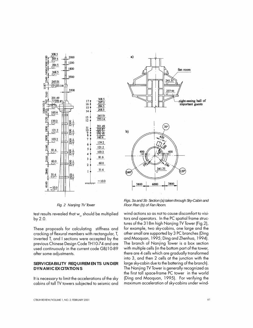
wind actions so as not to cause discomfort to visi-tors and operators. In the PC spatial frame struc-tures of the 318m high Nanjing TV Tower (Fig.2),for example, two sky-cabins, one large and theother small are supported by 3 PC branches (Dingand Maoquan, 1995; Ding and Zhenhua, 1994).The branch of Nanjing Tower is a box sectionwith multiple cells (in the bottom part of the tower,there are 4 cells which are gradually transformedinto 3, and then 2 cells at the junction with thelarge sky-cabin due to the battering of the branch).The Nanjing TV Tower is generally recognized asthe first tall space-frame PC tower in the world(Ding and Maoquan, 1995). For verifying themaximum acceleration of sky-cabins under wind-
Fig. 2 Nanjing TV TowerFigs. 3a and 3b Section (a) taken through Sky-Cabin andFloor Plan (b) of Fan Room.
CTBUH REVIEW/VOLUME 1, NO. 2: FEBRUARY 2001 62
pulses, one doctoral student and two master de-gree students, supervised by the first author atNIT, studied the dynamic behavior of this tower(Zhenhua, 1993; Meixiao, 1993). It was alsoinvestigated for seismic actions (Lin, 1993).
Following the stipulation of the Chinese Code, theacceleration of tower sky cabins under wind-pulsesshould not be over 0.15m/s2. Ding Dajun andRen Zhenhua adopted artificial pulse samples toconduct direct dynamic analysis and determinedthe accelerations of the small and large sky-cab-ins to be equal to 0.209m/s2 and 0.1m/s2, re-spectively (Ding and Zhenhua, 1994; Zhenhua,
1993). From the calculations it can be shownthat the acceleration of the small sky-cabin underwind-pulse loading cannot meet the serviceabil-ity requirement. The upper level of the small sky-cabin is reserved as a mechanical floor (Fig.3a)and the lower level is used as a sight-seeing floorfor distinguished guests (the general sight-seeinghall is located in the large sky-cabin). For control-ling the acceleration of the smaller sky-cabin, Reng(1993) suggested to set Tuned Liquid Dampers(TLDs) with diameters of 2.4m and 3.5m on thefloor of the fan room (Fig.3b). The dynamic analy-sis in Fig. 4a shows the enveloping curve of themaximum accelerations of each mass point be-fore the addition of control dampers. The enve-lope of maximum acceleration of each mass pointafter the installation of control dampers is shownin Fig. 4b (Zhenhua, 1993) where the accelera-tion of the small sky-cabin is reduced to 0.183m/s2 (Ding and Zhenhua, 1994). Even with damp-ers, the controlling effect is only 12.4% and is stillbelow the service requirement. This problem shouldbe studied further.
Cheng Mexiao’s master’s thesis (Meixio, 1993)studied the use of Tuned Mass Dampers (TMDs)for controlling the pulsating wind response of theNanjing TV Tower. She pointed out that the con-trolling effect for the small sky-cabin is larger withthe increase of the mass of the TMD system.However, she also found that if the economic massratio (i.e., the ratio of the mass of the TMD systemto that of the small sky-cabin) of 0.05 is used,then the optimum damping ratio is 0.1 and theoptimum frequency ratio (i.e., the ratio of fre-quency of TMD to the 1st frequency of the struc-ture) is 1.037.
An Lin’s thesis (Lin, 1993) applied the TMD sys-tem to control the vibration due to wind-pulse andobtained the optimum controlling parameters byusing the optimum controlling program. Fig. 5shows the time-history-acceleration response curvebefore and after controlling (Lin, et. al., 1995).The maximum acceleration of the small sky-cabinis 0.24m/s2 and is reduced to 0.21m/s2 aftercontrolling. The controlling effect is 12.5% whichis the same as given in by Ding and Maoquan
Figs. 4a and 4b Acceleration Diagrams of Sky-Cabinsubjected to Dynamic Wind Loads before (a) and after (b)installation of Tuned Liquid Dampers
CTBUH REVIEW/VOLUME 1, NO. 2: FEBRUARY 2001 63
(1995) and Ding and Zhenhua (1994). Themaximum acceleration is slightly different due tothe fact that the wind-pulse sample used and themasses calculated were slightly different. The seis-mic action was also investigated and the controllingeffect reached 50% (Lin, et. al., 1995; Lin and Ding,2000).
CONCLUSIONS
For the calculation of stiffness and cracking ofconcrete members under static loading, the firstauthor suggested a series of proposals, which areapplicable to rectangular, T, inverted T, I, andannular sections currently used in engineeringpractice. They also can be used for RC, PC, andlight-weight concrete members subjected to flex-ure and eccentric forces under short- and long-term loading. This method of calculation appearsto be more convenient, seems to provide a highdegree of accuracy (Ding, 1989, 1990,1992and 1992b; Ding, et. al., 1985 and 1986)and can satisfactorily meet design requirements.It is important to note that the study of the NanjingTV Tower – a tall structure subjected to dynamicactions – is preliminary and, therefore, it is neces-
sary to conduct more research before definitiveconclusions can be drawn.
REFERENCES
Ding, D., 1989CALCULATION FOR DEFLECTION OF CONTINU-OUS REINFORCED CONCRETE BEAMS IN CON-SIDERATION OF MOMENT REDISTRIBUTION (IN-CLUDING CHINESE CONGRATULATORY POEMWITH ENGLISH TRANSLATION), 75o compleannodi Franco Levi, Testimonianze, Politecnico di Torino,September, p. 43, pp. 279–283.
Ding, D., 1990CALCULATION FOR DEFLECTION OF CONTINU-OUS REINFORCED CONCRETE BEAMS IN CON-SIDERATION OF MOMENT REDISTRIBUTION, Pro-ceedings of JSCE, pp. 25–36.
Ding, D., 1992aRESEARCH IN CHINA ON THE STIFFNESS ANDCRACKING CHARACTERISTICS OF CONCRETEMEMBERS, Proceedings of the Institution of CivilEngineers; Structures & Buildings, pp. 171–178.
Fig. 5 Analysis with and without Tuned Mass Dampers installed in the Nanjing TV Tower
CTBUH REVIEW/VOLUME 1, NO. 2: FEBRUARY 2001 64
Ding, D., 1992bEXPERIMENTAL STUDIES AND CALCULATIONPROPOSALS FOR STIFFNESS OF PPC FLEXURALMEMBERS, Proceedings of the FIP Symposium ’92,Budapest, Hungary, May, pp. 345–350.
Ding, D. and Maoquan, X., 1995SPATIAL FRAME TV TOWER, NANJING, CHINA,Structural Engineering International, Journal ofIABSE, No.3, pp. 149–150.
Ding, D. and Zhenhua, R., 1994DESIGN TESTING AND ANALYSES OFNANJING’s TV TOWER, Concrete International,November, pp. 42–44.
Ding, D., et al., 1985EXPERIMENTAL RESEARCH OF REINFORCEDCONCRETE AND PRE-STRESSED CONCRETEBEAMS UNDER LONG TERM LOADING,Stavebnicky Casopis (Building Journal of SlovakianAcademy), 33, pp. 489–518.
Ding, D., et al., 1986EXPERIMENTAL RESEARCH AND CALCULATIONPROPOSALS FOR STIFFNESS AND CRACK WIDTHOF REINFORCED CONCRETE MEMBERS,Stavebnicky Casopis (Building Journal ofSlovakian Academy), 34, pp. 471–497
Lin, A., 1993STUDY OF A SEISMIC CONTROL OF P-TMD ANDOPTIMAL CONTROL FOR NJTV TOWER (in Chi-nese), thesis for MS degree from NIR, China, Feb-ruary, p. 77.
Lin, A., Ding, D., 2000A STUDY ON THE P-TMD CONTROL FOR SEISMICAND WIND VIBRATION OF THE NANJING TVTOWER, Journal of Structural Engineering, Vol. 26,No. 4, January, pp. 283–287.
Lin, A., Ding, D., Qin, L., 1995STUDY OF VIBRATION CONTROL OF THENANJING TV TOWER BY P-TMD, Building Struc-ture (in Chinese), No. 7, pp. 14–18
Meixiao, C., 1993SIMULATION OF MULTIDIMENSIONAL ARTIFI-CIAL PULSATING WIND AND RESEARCH FORWIND-PULSE CONTROL OF P-TMD ON HIGH-RISE STRUCTURES (in Chinese), thesis for MS de-gree from NIT, China, February, p. 72.
Zhenhua, R., 1993FUNDAMENTALS OF A TLD DEVICE AND ITSAPPLICATION TO VIBRATION CONTROL OF THENJTV TOWER (in Chinese), Ph.D. dissertation fromNIT, May, p. 57.