82
Configuration Tool for Imaging Devices (CTFID) VP-CFGSFT en Software Manual

Configuration Tool for Imaging Devices(CTFID)VP-CFGSFT
en Software Manual


Table of contents
1 Introduction 52 System Requirements 73 Installing the CTFID Software 84 Connections 125 Connecting via the USB Port 135.1 Connecting the VP-USB Configuration Tool to Your PC 135.2 Connecting the MIC-USBCVTR2 Cable to Your PC 14
6 Connecting via Serial port (VP-RS2BLNX Configuration Tool) 156.1 Connecting the VP-RS2BLNX (Bilinx) Configuration Tool to Your PC 16
7 Connecting RS-232 to an AUTODOME camera 187.1 Connecting the AUTODOME camera to Your PC 18
8 Starting the CTFID Application 209 Using Help 249.1 Finding Information 249.2 Printing Help 24
10 Using the Configuration Tool 2610.1 Main Menu Buttons 2710.2 Offline Configuration Window 2710.2.1 Overwriting Configuration Settings 2810.3 Online Configuration Window 2910.4 Virtual Keyboard Window 3010.4.1 Panning/Tilting AutoDome and MIC Series Cameras via the Virtual Keyboard 3110.4.2 Using the Virtual Keyboard with DINION Cameras 3210.5 AUX Commands Dialog Box 3210.5.1 Entering AUX Commands 3310.6 Logs Window 3310.6.1 Downloading and Saving Diagnostic Log Information 3310.7 Central Workspace 3510.8 System Feedback 3610.9 Operations Column 37
11 Configuration Settings 3911.1 Saving a Configuration File 3911.2 Uploading/Downloading Specific Configuration Settings 3911.3 Downloading All Configuration Settings 4111.4 Uploading All Configuration Settings to a Device 4111.5 Migrating Configuration Settings 4111.6 Uploading Firmware to a Device 4311.7 Uploading Firmware to a VG4/VG5 Series AUTODOME 44
12 Settings Tree Options 4613 Troubleshooting 6713.1 Confirming System Connection between the PC and the Device 6713.2 Identifying a Device Error 6813.3 Identifying the Version of CTFID Software 69
14 AUX Keyboard Commands 7014.1 Commands, AUTODOME 7014.2 Commands, MIC Series Optical Camera 73
Configuration Tool for ImagingDevices (CTFID)
Table of Contents | en 3
Bosch Security Systems, Inc. Software Manual 2013.09 | 3.16 |

14.3 Commands, MIC 612 Thermal Camera 77
Index 80
4 en | Table of ContentsConfiguration Tool for Imaging
Devices (CTFID)
2013.09 | 3.16 | Software Manual Bosch Security Systems, Inc.

IntroductionThe Configuration Tool for Imaging Devices (CTFID) from Bosch Security Systems increasesefficiency for CCTV installers and service personnel.CTFID uses Bilinx technology, a bidirectional communication method, embedded in the videosignal of all of the latest analog DINION, FLEXIDOME, AUTODOME, and MIC Series camerasfrom Bosch. Using CTFID, technicians can check status, change settings, control pan/tilt/zoom(PTZ), and even update firmware from virtually anywhere along the video cable. This reducesthe time for troubleshooting and service, while providing more accurate setup and adjustment,all without running additional wires or boxes.CTFID includes two components:– One (1) CD-ROM containing the software application– Configuration Tool hardware (VP-USB, interface between your computer and an imaging
device)CTFID is compatible with older Bosch cameras including the Unity Dome series and UPH 2Dand 3D series. (See the table below for a list of compatible devices.Note: This list does not identify every model in each series of compatible devices.)
ENV Series EnviroDome
G3B Series BasicDome
The following AUTODOME Series:G3A Series IndoorEasy IIVG4 100 SeriesVG4 200 SeriesVG4 300 SeriesVG4 500i SeriesVG5 100 SeriesVG5 600 Series
The following DINION Series:LT SeriesXF Series2X Series4000 AN5000 AN
DINION IR Imager (VEI-30 Series)
EX65 Explosion-protected Camera and Illuminator
1
Configuration Tool for ImagingDevices (CTFID)
Introduction | en 5
Bosch Security Systems, Inc. Software Manual 2013.09 | 3.16 |

The following FLEXIDOME Series:DN SeriesVF SeriesXT Series2X Series5000 ANcorner 9000 IR
High Speed Positioning System units
The following MIC Series:MIC550MIC550IRMIC612
Unity Dome Series
6 en | IntroductionConfiguration Tool for Imaging
Devices (CTFID)
2013.09 | 3.16 | Software Manual Bosch Security Systems, Inc.

System RequirementsThe following are the minimum system requirements to run the Configuration Tool for ImagingDevices software application:– PC operating platform: Windows® 2000, Windows XP®, Windows® Vista, or Windows® 7
(32- and 64-bit versions)– Processor: 200 MHz Pentium with MMX (or equivalent)– RAM memory: 256 MB (dependent upon the operating system)– Hard disk space: 50 MB– Video system: 1024 x 768 with 16-bit color– CD-ROM drive, if installing the software from a CD– Connectivity: a free USB port (1.1 or higher)– Connectivity through serial interface
2
Configuration Tool for ImagingDevices (CTFID)
System Requirements | en 7
Bosch Security Systems, Inc. Software Manual 2013.09 | 3.16 |

Installing the CTFID SoftwareThis chapter includes instructions for installing the software for the Configuration Tool forImaging Devices. Before connecting to a compatible device, install the software.
Installing the Software4 Insert the supplied CD into your CD drive.
If the InstallShield Wizard does not start automatically, open the CD manually by clickingStart > Run > Browse. Locate and open the autorun.exe file. The Macromedia FlashPlayer window appears, prompting you to select one of the following options: InstallConfiguration Tool, User Guide, View the Readme file, and Exit. Click InstallConfiguration Tool to install the software.The Choose Setup Language window appears.
Figure 3.1: Choose Setup Language window
4 Select a language from the list, and then click Next. The main CTFID window and thePreparing Setup window appear momentarily, and then the Welcome window appears.
3
8 en | Installing the CTFID SoftwareConfiguration Tool for Imaging
Devices (CTFID)
2013.09 | 3.16 | Software Manual Bosch Security Systems, Inc.

Figure 3.2: Welcome window Initiating the InstallShield Wizard setup
4 Click Next to continue installing the application. The License Agreement windowappears.
Figure 3.3: License Agreement window
4 Click Yes to accept the terms of the License Agreement. The Start Copying Files windowappears.
Configuration Tool for ImagingDevices (CTFID)
Installing the CTFID Software | en 9
Bosch Security Systems, Inc. Software Manual 2013.09 | 3.16 |

Figure 3.4: Start Copying Files window
4 Click Next. The Setup Status window appears; CTFID begins configuring the softwareinstallation. When installation finishes, the Select Options window appears. Click Next.
Figure 3.5: Select Options window
4 Check the appropriate box(es), and then click Next. The InstallShield Wizard Completewindow appears.
10 en | Installing the CTFID SoftwareConfiguration Tool for Imaging
Devices (CTFID)
2013.09 | 3.16 | Software Manual Bosch Security Systems, Inc.

Figure 3.6: InstallShield Wizard Complete window
4 Click Finish to complete the installation. The CTFID application launches and/or theInstruction Manual and ReadMe file appear(s) automatically (if you selected those checkbox(es)).
Configuration Tool for ImagingDevices (CTFID)
Installing the CTFID Software | en 11
Bosch Security Systems, Inc. Software Manual 2013.09 | 3.16 |

ConnectionsThere are three (3) possible connection types to link the CTFID software to the imagingdevice.The first two (2) choices communicate via coax using the Bilinx protocol. These two (2)choices connect to either the USB or serial COMM port of the PC. The CTFID is supplied witha VP-USB adapter that plugs into any USB-compliant port supported by a Windows® operatingsystem. Once the CTFID software is loaded, the adapter communicates over the video signalfrom any Bilinx-enabled camera or AUTODOME.
Notice!
It is recommended that the CTFID software be installed before connecting the hardware to
the port. Refer to Installing the CTFID Software, page 8 for additional information.
The third choice is direct RS-232 connection between the PC COMM port and an AUTODOMEcamera.
4
12 en | ConnectionsConfiguration Tool for Imaging
Devices (CTFID)
2013.09 | 3.16 | Software Manual Bosch Security Systems, Inc.

Connecting via the USB PortBilinx devices may be connected to a PC running the CTFID via a USB connection. All Bilinxdevices can be connected to the computer with the VP-USB cable. MIC Series 550 and MICSeries 612 cameras can also be connected to the computer via the MIC-USB485CVTR2 cable.
Connecting the VP-USB Configuration Tool to Your PCThe VP-USB must be connected to a T-connector. The other end of the T-connector must beconnected to a device with 75 ohm termination. If your preference is to view the video output,then use a CCTV monitor/DVR. See the figure below for an example of the connections.
Notice!
Some MIC Power Supply Boxes contain two coaxial video outputs. The MIC612 has two
outputs. You must use the optical video output to upload the firmware. Do NOT use the
switching thermal output!
VP-USB
Figure 5.1: Connecting the VP-USB Configuration Tool
Number Description
1 Typical AUTODOME, MIC Series 550, MIC Series 612, or other Bilinxdevice
2 PC running CTFID software
3 USB port
4 VP-USB adapter
5 BNC “T” connector
6 Coax to input of monitor (terminated at 75 ohms)
7 Typical CCTV monitor
8 75-ohm terminator (must be used if not connecting to a monitor/DVR)
5
5.1
Configuration Tool for ImagingDevices (CTFID)
Connecting via the USB Port | en 13
Bosch Security Systems, Inc. Software Manual 2013.09 | 3.16 |

Making the Connection1. Insert the Configuration Tool USB cable into a USB port on your computer. The other end
of the USB cable is permanently attached to the Configuration Tool hardware.2. Connect the coax from the VP-USB to the male connection of the BNC “T” connector.3. Connect a coaxial cable to the input of the monitor.4. Connect the other end of the monitor’s coaxial cable into one of the female connections
on the BNC “T” connector, or connect a 75-ohm terminator to the other end of the BNC“T” connector.
5. Connect the coax from the camera to the other female connection of the BNC “T”connector.
Connecting the MIC-USBCVTR2 Cable to Your PCThe MIC-USB485CVTR2 is a signal converter allowing connection of MIC Series cameras to aPC USB port to facilitate easy set up and configuration when used with the CTFID software.Refer to the MIC Series Power Supply Installation Manual and to the MIC Series USB485CVTR 2User Guide for details about this connection.
Making the Connection1. Disconnect the MIC Series power supply from the mains power supply.2. Open the MIC Series power supply.3. Locate the telemetry header (HD5). Unplug any connectors to telemetry headers HD4 or
HD5.4. Connect the MIC-USB485CVTR2 cable with the Molex connector to HD5. Connect the 5-
pin screw down terminal end to the MIC-USB485CVTR2.5. Plug the USB connector on the long cable of the MICUSB485CVTR2 to an available USB
port. The PC should detect a new device and inform you that the hardware has beensuccessfully installed.
5.2
14 en | Connecting via the USB PortConfiguration Tool for Imaging
Devices (CTFID)
2013.09 | 3.16 | Software Manual Bosch Security Systems, Inc.

Connecting via Serial port (VP-RS2BLNX ConfigurationTool)To see the device output, use a CCTV monitor.1. Plug the coax connected to the imaging device to one of the BNC connectors of the VP-
RS2BLNX (which can operate in either RS-232 or RS-485 mode).2. Connect another coax between the second BNC connector and the CCTV monitor.3. Ensure that the monitor is either auto-terminating or is set to low impedance.Note: Refer to , page 15 for an example of the connections to a typical CCTV monitor.
Figure 6.1: VP-RS2BLNX connections
Number
Description
1 Power and serial connection
2 Selects mode and baud rate
3 BNC connections, passive loop-through, high impedance, video input 1 Vpp nominal, 2 Vpp max.
Figure 6.2: Connecting the VP-RS2BLNX Configuration Tool
6
Configuration Tool for ImagingDevices (CTFID)
Connecting via Serial port (VP-RS2BLNX Configuration Tool) | en 15
Bosch Security Systems, Inc. Software Manual 2013.09 | 3.16 |

Number Description
1 Typical AutoDome (version 5.10 or higher), and any other Bilinx device
2 Coax IN
3 Terminal block
4 VP-RS2BLNX
5 PC running CTFID software
6 RS-232
7 Power supply (not provided)
8 Coax OUT
9 Typical CCTV monitor
See also– Installing the CTFID Software, page 8– Connecting the VP-RS2BLNX Configuration Tool, page 15
Connecting the VP-RS2BLNX (Bilinx) Configuration Tool toYour PCPin 1 and 2 of the terminal block are for the connections for the external power supply (notprovided). The external power supply should be either 12-28 VAC (50/60 Hz) or 12-40 VDC(polarity independent), and galvanically insulated from video, RS-232 ground, and encasing.
Notice!
The Serial to Bilinx converter interface shall be supplied by a self-limited power source of less
than 15 VA. Reinforced insulation is provided between input and output by safety transformer
and distances on the PCB. USA/Canada: The Serial to Bilinx converter is a product for
INDOOR use. It is intended for use with a UL-listed Class 2 power supply.
4 Connect a cable between the terminal block of the VP-RS2BLNX Configuration Tool to theserial port on the computer. See the pin out table below for the proper connections.
Pin # Description
PC DB9
2 RxD
3 TxD
5 GnD
VP-RS2BLNX terminal block
Pin 3 GND
Pin 4 TxD
Pin 5 RxD
-or-
6.1
16 en | Connecting via Serial port (VP-RS2BLNX Configuration Tool)Configuration Tool for Imaging
Devices (CTFID)
2013.09 | 3.16 | Software Manual Bosch Security Systems, Inc.

Pin # Description
VP-RS2BLNX terminal block
Pin 6 Tx/Rx+ (B)
Pin 7 Tx/Rx- (A)
Pin 8 Do not connect
Pin 9 Do not connect
Pin 10 GND
Dip switch Description
8 On: RS-485, Off: RS-232
7 RS-232 baud rate (On: 4800, Off: 9600 Bps)
7-1 RS-485 address (0 to 127)
Table 6.1: Mode and Baud Rate Selections
1. Connect the coax from the Bilinx device to one of the BNCs on the VP-RS2BLNX.2. Connect a second coaxial cable from the looping output of the VP-RS2BLNX to the input
of the CCTV monitor.
Configuration Tool for ImagingDevices (CTFID)
Connecting via Serial port (VP-RS2BLNX Configuration Tool) | en 17
Bosch Security Systems, Inc. Software Manual 2013.09 | 3.16 |

Connecting RS-232 to an AUTODOME camera
Figure 7.1: Connecting RS-232 to an AUTODOME camera
Number Description
1 AUTODOME camera (VG4 Series, VG5 100 Series, or VG5 600 Series)
2 PC running CTFID software
3 RS-232
4 Coax to input of monitor
5 Typical CCTV monitor
Connecting the AUTODOME camera to Your PC4 Make the RS-232 cable using the table below.
Pin # Description
PC DB9
2 RxD
3 TxD
5 GnD
P105 (AUTODOME 200, 300, 500)
5 RxD
4 TxD
6 GnD
1. Connect the DB9 connector to the comm port of the PC.2. Connect P105 to the camera.3. Use coax to connect the Video output of the camera to a CCTV monitor.4. Reposition the slide switch located on the main board of the camera. Slide the switch
toward the camera head, inward and away from the LEDs. See , page 18.
7
7.1
18 en | Connecting RS-232 to an AUTODOME cameraConfiguration Tool for Imaging
Devices (CTFID)
2013.09 | 3.16 | Software Manual Bosch Security Systems, Inc.

Figure 7.2: RS-232
Configuration Tool for ImagingDevices (CTFID)
Connecting RS-232 to an AUTODOME camera | en 19
Bosch Security Systems, Inc. Software Manual 2013.09 | 3.16 |

Starting the CTFID Application4 Double-click the Configuration Tool for Imaging Devices icon located on your desktop
window.- or -Click the Windows Start button, and then select Programs > Bosch Configuration Toolfor Imaging Devices > Configuration Tool for Imaging Devices.
Figure 8.1: Initial window
4 By default, the device tries to connect automatically to a device over Bilinx. Theapplication displays the following message for approximately 20-30 seconds:
Figure 8.2: Checking device window
4 If a device is detected, proceed to Using the Configuration Tool, page 26 for detailsabout using the CTFID software. If a device is not detected within 1 minute, or if youinterrupt the process by clicking the Cancel button, you have the option to select analternate interface or to work in offline mode.
8
20 en | Starting the CTFID ApplicationConfiguration Tool for Imaging
Devices (CTFID)
2013.09 | 3.16 | Software Manual Bosch Security Systems, Inc.

Figure 8.3: Alternate Interface Dialog box
4 To select an alternate interface, select the appropriate Interface option. Click Continue(see , page 20). Select the appropriate interface type and then proceed to Step 5.- or -To work in offline mode, select the Load Configuration option. Click Continue and thenproceed to Step 6.
Figure 8.4: Select Interface window
4 The application attempts to detect a device.
If the application detects a device, the Overview window opens. (See Main screen, page26 of Chapter 4).If the application does not detect a device, the Load Configuration window opens.
Configuration Tool for ImagingDevices (CTFID)
Starting the CTFID Application | en 21
Bosch Security Systems, Inc. Software Manual 2013.09 | 3.16 |

Figure 8.5: Load Configuration window
4 To open an existing configuration file, select the Configuration File option. ClickContinue and then proceed to Step 7.- or -To create a new configuration file, select the Device Template option. Click Continue andthen proceed to Step 8.
Figure 8.6: Open file dialog box
4 Navigate to the configuration file, and then click Open. Proceed to Using the ConfigurationTool, page 26.
22 en | Starting the CTFID ApplicationConfiguration Tool for Imaging
Devices (CTFID)
2013.09 | 3.16 | Software Manual Bosch Security Systems, Inc.

Figure 8.7: Choose a device window
1. Highlight the name of the device for which you want to create a new configuration, andthen select a Video Type, NTSC or PAL. Click Continue. The Overview window appears,displaying the default settings for the device.
2. Make the changes to the template. Click the Save Configuration button. The Save Asdialog box opens.
Figure 8.8: Save As window
3. Navigate to the folder where you want to save the configuration file.4. Type a name for the configuration file in the File name field.5. Click Save. The configuration file is saved in the specified folder.
See also– Using the Configuration Tool, page 26– Starting the CTFID Application, page 20– Using the Configuration Tool, page 26
Configuration Tool for ImagingDevices (CTFID)
Starting the CTFID Application | en 23
Bosch Security Systems, Inc. Software Manual 2013.09 | 3.16 |

Using HelpTo use the Contents, Index, or Search, click Help on the Help menu. Use the buttons and linksto navigate.To access Help on a window or dialog box:
– Click on the toolbarOR
– Press F1 for Help on any program window or dialog box.
Finding InformationYou can find information in Help in several ways.To find information in the online Help:1. On the Help menu, click Help.2. If the left-hand pane is not visible, click the Show button.3. In the Help window, do the following:
Click: To:
Contents Display the table of contents for the online Help. Click each book to displaypages that link to topics, and click each page to display the corresponding topicin the right-hand pane.
Index Search for specific words or phrases, or select from a list of index keywords.Double-click the keyword to display the corresponding topic in the right-handpane.
Search Locate words or phrases within the content of your topics. Type the word orphrase in the text field, press ENTER, and select the topic you want from the listof topics.
Text from the user interface appears in bold.4 The arrow invites you to click on the underlined text or to click an item in the application.
4 Click to get step-by-step instructions:
Related windows4 Click to display a topic with information on the application window you are currently
using. This topic provides information on the window controls.
Notice!
Notices inform you of essential but non-critical information. Read these messages carefully, as
any directions or instructions contained therein can help you avoid making mistakes.
Caution!
Cautionary messages should be heeded to help you reduce the chance of losing data or
damaging the system.
Printing HelpWhile using Bosch Video Management System online Help, you can print topics andinformation directly from the browser window.
9
9.1
9.2
24 en | Using HelpConfiguration Tool for Imaging
Devices (CTFID)
2013.09 | 3.16 | Software Manual Bosch Security Systems, Inc.

To print a Help topic:1. Right-click in the right pane and select Print.
The Print dialog box opens.2. Click Print. The topic is printed to the specified printer.
Configuration Tool for ImagingDevices (CTFID)
Using Help | en 25
Bosch Security Systems, Inc. Software Manual 2013.09 | 3.16 |

Using the Configuration ToolMain screenThe CTFID main screen contains all the options for changing a template, configuring a liveview, displaying specific device information, downloading information, changing devicesettings, and manipulating a device. By default, the CTFID opens to the Overview window,which displays general information about the device, the application environment, and thestate of the application. The data includes specific device information.The main screen is divided into four (4) segments.
Figure 10.1: Overview / main window
1 Main menucolumn
The left-hand column represents the main menu, which includesthe Overview, Offline Config, Online Config, Keyboard, Logs,and Exit buttons.
2 Centralworkspace
The middle section represents the central workspace, whichincludes device information or provides access to user settings.
3 Systemfeedback
The bottom segment represents the system feedback, whichincludes device type, alarm, connectivity status, and motioninformation.
4 Operationscolumn
The operations column includes buttons for creating, saving,uploading, downloading, restoring, printing, changing thelanguage, and accessing the online Help system.
10
26 en | Using the Configuration ToolConfiguration Tool for Imaging
Devices (CTFID)
2013.09 | 3.16 | Software Manual Bosch Security Systems, Inc.

Main Menu Buttons
Button Description
Opens the Overview window. The Overview window displays general information about the device,the application environment, and the state of the application. The data includes specific deviceinformation.
Opens the Offline configuration window. The Offline configuration window allows you to establishsettings in a new configuration file or to modify settings in an existing configuration file.Note: The CTFID software allows two (2) files to be open simultaneously:– Online configuration file: contains the current settings for the connected device.– Offline configuration file: contains either the settings saved in a specific configuration file or the
default device settings.
Opens the Online configuration window. The Online configuration window displays the currentsettings for the device connected to the Configuration Tool software. Changes made to the settings inOnline mode are reflected in the device.
Opens the Virtual Keyboard window. The virtual keyboard controls various settings, depending onthe device type. In Online mode, changing the settings on this screen automatically changes thesettings on the device.
Opens the Logs window. The Logs window allows you to download diagnostic information from theconnected device. The downloaded diagnostic information can be saved as a text file.Note: The Logs button is enabled only when the CTFID software is connected to a VG4 SeriesAutoDome.
Exits the Configuration Tool for Imaging Devices.
Offline Configuration WindowThe Offline configuration window allows you to establish settings in a new configuration file,or to change settings in an existing configuration file. You can download and save data so thatit can be manipulated and uploaded to other devices.To access the window, click the Offline Config button. Settings are arranged in groups suchas Camera, Lens, PTZ, Display, Alarm, and Miscellaneous.
10.1
10.2
Configuration Tool for ImagingDevices (CTFID)
Using the Configuration Tool | en 27
Bosch Security Systems, Inc. Software Manual 2013.09 | 3.16 |

Figure 10.2: Offline configuration window
Notice!
The headings and settings tree are available based on the device selected. For detailed
information about the possible settings, refer to the installation instructions manual for the
specific device.
Overwriting Configuration SettingsIf you are working in an open file and would like to open another file in Offline mode, thefollowing Information dialog box opens:
10.2.1
28 en | Using the Configuration ToolConfiguration Tool for Imaging
Devices (CTFID)
2013.09 | 3.16 | Software Manual Bosch Security Systems, Inc.

Figure 10.3: Information dialog box
The Information dialog box provides several options:– Click Yes to open a Save As dialog box. Name the file and save it.– If you click No, the changes to the file will not be saved. The Load Configuration dialog
box opens. Choose a different file or device template.– Click Cancel and the dialog box closes.
Online Configuration WindowThe Online configuration window allows you to view the current settings of the deviceconnected to the CTFID. When device settings are changed in Online mode, the changes areimmediately conveyed to the remote device. To access the window, click the Online Configbutton. As with the Offline Configuration window, settings are arranged in groups such asCamera, Lens, PTZ, Display, Alarm, and Miscellaneous.
10.3
Configuration Tool for ImagingDevices (CTFID)
Using the Configuration Tool | en 29
Bosch Security Systems, Inc. Software Manual 2013.09 | 3.16 |

Figure 10.4: Online configuration window
Notice!
The headings and settings tree are available based on the device selected. For detailed
information about the possible settings, refer to the installation instructions manual for the
specific device.
Virtual Keyboard WindowThe Virtual Keyboard window allows setting adjustments. If a PC monitor is connected to thedevice, the effects of the setting changes can be viewed. To access the window, click theKeyboard button.
Notice!
The layout of the Virtual Keyboard window varies depending on the device. The functionality
described below may not be available on all devices.
10.4
30 en | Using the Configuration ToolConfiguration Tool for Imaging
Devices (CTFID)
2013.09 | 3.16 | Software Manual Bosch Security Systems, Inc.

Panning/Tilting AutoDome and MIC Series Cameras via the VirtualKeyboard1. Place the cursor on the Pan/Tilt control (item 1 in the figure below), and then click and
hold down the left mouse button.2. Double-click the left mouse button to lock the cursor to the control.3. Move the mouse to move the camera.4. Single-click the left mouse button to release the cursor.When used with a variable-speed device, the further the cursor is from the center of thecontrol, the faster the device will pan.
Figure 10.5: AutoDome Virtual Keyboard window
1 Pan/Tilt Moves the device.
2 AUX Opens the AUX Commands dialog box.
3 Focus Widens the scope of the focus lens.
4 Focus Narrows the scope of the focus lens.
5 Zoom Zooms in on the subject of the device.
6 Zoom Zooms out and widens the field of view.
7 Iris Increases the light level for proper exposure.
8 Iris Decreases the light level for proper exposure.
10.4.1
Configuration Tool for ImagingDevices (CTFID)
Using the Configuration Tool | en 31
Bosch Security Systems, Inc. Software Manual 2013.09 | 3.16 |

See also– Panning/Tilting AutoDome and MIC Series Cameras via the Virtual Keyboard, page 31
Using the Virtual Keyboard with DINION Cameras1. Place the cursor on the Enter control (item 5 in the figure below).2. Click once to open the Mode menu.3. Click to open the submenus.4. Click and hold to open the Install menu.5. Click to open the submenus.
Figure 10.6: DINION Virtual Keyboard window
1 Pan/Tilt Moves the cursor up.
2 Pan/Tilt Moves the cursor to the right.
3 Pan/Tilt Moves the cursor down.
4 Pan/Tilt Moves the cursor to the left.
5 Enter Opens menus and functions as an enter button.
6 AUX Opens the AUX Commands dialog box.
AUX Commands Dialog BoxThe AUXCommands dialog box simulates the hardware keypad, and allows direct entry of theAUX command. To open the AUX Commands dialog box, click the AUX button on the VirtualKeyboard window.
10.4.2
10.5
32 en | Using the Configuration ToolConfiguration Tool for Imaging
Devices (CTFID)
2013.09 | 3.16 | Software Manual Bosch Security Systems, Inc.
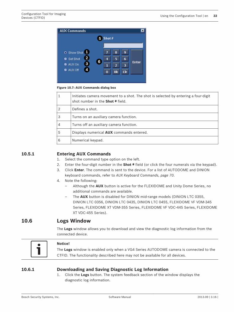
Figure 10.7: AUX Commands dialog box
1 Initiates camera movement to a shot. The shot is selected by entering a four-digitshot number in the Shot # field.
2 Defines a shot.
3 Turns on an auxiliary camera function.
4 Turns off an auxiliary camera function.
5 Displays numerical AUX commands entered.
6 Numerical keypad.
Entering AUX Commands1. Select the command type option on the left.2. Enter the four-digit number in the Shot # field (or click the four numerals via the keypad).3. Click Enter. The command is sent to the device. For a list of AUTODOME and DINION
keyboard commands, refer to AUX Keyboard Commands, page 70.4. Note the following:
– Although the AUX button is active for the FLEXIDOME and Unity Dome Series, noadditional commands are available.
– The AUX button is disabled for DINION mid-range models (DINION LTC 0355,DINION LTC 0356, DINION LTC 0435, DINION LTC 0455, FLEXIDOME VF VDM-345Series, FLEXIDOME XT VDM-355 Series, FLEXIDOME VF VDC-445 Series, FLEXIDOMEXT VDC-455 Series).
Logs WindowThe Logs window allows you to download and view the diagnostic log information from theconnected device.
Notice!
The Logs window is enabled only when a VG4 Series AUTODOME camera is connected to the
CTFID. The functionality described here may not be available for all devices.
Downloading and Saving Diagnostic Log Information1. Click the Logs button. The system feedback section of the window displays the
diagnostic log information.
10.5.1
10.6
10.6.1
Configuration Tool for ImagingDevices (CTFID)
Using the Configuration Tool | en 33
Bosch Security Systems, Inc. Software Manual 2013.09 | 3.16 |

Figure 10.8: Logs window download diagnostic log information
2. Click the Download button.3. Click the Save Logs button. The Save As dialog box opens.
34 en | Using the Configuration ToolConfiguration Tool for Imaging
Devices (CTFID)
2013.09 | 3.16 | Software Manual Bosch Security Systems, Inc.

Figure 10.9: Save As dialog box
4. Navigate to the folder where you want to save the log file.5. Type a name for the log file in the File name field.6. Click Save. The configuration file is saved in the specified folder.
Central WorkspaceThe central workspace displays the main menu windows. For example, when the OfflineConfig button is clicked and a configuration file or device template has been selected, thecentral workspace displays a two-pane window. The settings tree and the windows in thecentral workspace vary depending on the device selected. The settings are divided intodifferent groups. For detailed information about the possible settings, refer to the installationinstructions manual for your specific device.
10.7
Configuration Tool for ImagingDevices (CTFID)
Using the Configuration Tool | en 35
Bosch Security Systems, Inc. Software Manual 2013.09 | 3.16 |

Figure 10.10: Central workspace with settings tree and device settings
System FeedbackThe system feedback section includes device, alarm, and motion information. The Status textbox displays specifics on the connected device in Online mode.
10.8
36 en | Using the Configuration ToolConfiguration Tool for Imaging
Devices (CTFID)
2013.09 | 3.16 | Software Manual Bosch Security Systems, Inc.

1 Indicates the name of the device currently connected in Online mode.
2 Indicates the video type of the device currently connected in Online mode.
3 Confirms that the device is connected to the Configuration Tool for Imaging Devices.
When a device is not connected, a red X appears.
4 Confirms that the application is displaying the current device settings. Any changesmade to the settings are immediately applied. Other messages may include:– Confirmation message: When you change settings on the device, the setting
change is noted in this box. If no message appears, the device has not receivedthe change.
– Error message: If there is a problem with the device, an error message mayappear. Possible causes may be a connection problem or an incompatibilityissue.
5 Detects the alarm condition of a connected device (icon turns red). Click the icon toacknowledge the alarm; the icon then returns to its normal gray color.Note: When the VG4 Series AUTODOME detects the alarm condition, the alarm iconturns red and remains red until the alarm condition is cleared. The VG4 Series willnot acknowledge an alarm by the icon being clicked.Note: The Alarm icon will always be present, but the associated functionality maynot be available for all devices.
6 Detects motion of a connected device (icon turns red). Click the icon toacknowledge the motion. The icon returns to its normal gray color.Note: The Motion icon will always be present, but the associated functionality maynot be available for all devices.
Operations Column
Button Description
Creates a new or opens an existing configuration file. When in Online mode, the configurationfile opens in Offline mode by default.
Saves the configuration file on which you are working.
Uploads the open configuration file to the device. The Upload Configuration button is onlyavailable when working in Offline mode.
Downloads the configuration file from the device to Offline mode.Note: If you click this button when working in Offline mode and are not connected to a device,the following error message appears: There is no compatible device currently connected.
10.9
Configuration Tool for ImagingDevices (CTFID)
Using the Configuration Tool | en 37
Bosch Security Systems, Inc. Software Manual 2013.09 | 3.16 |

Button Description
Uploads a firmware upgrade directly to the device. Note: Not available on the following models:DINION LTC 0355, 0356, DINION LTC 0435, and 0455; FLEXIDOME VF VDM-345 Series;FLEXIDOME XT VDM-355 Series; FLEXIDOME VF VDC-445 Series; and FLEXIDOME XT VDC-455Series.
Restores all settings in the device to factory defaults. CTFID subsequently downloads allsettings from the device.Note: The functionality described above is only available when a VG4 Series AUTODOME camerais connected to CTFID software.
Prints the offline configuration settings when in Offline mode.
Migrates the current offline or online settings of one AUTODOME or MIC Series to anotherdevice.
Automatically checks all of the Select check boxes and uploads all changes to the device (onlyappears when in Offline mode).
Changes the language displayed by the Configuration Tool software.Note: The application must be restarted in order to affect the language setting change.
Accesses the Configuration Tool software online Help system.
38 en | Using the Configuration ToolConfiguration Tool for Imaging
Devices (CTFID)
2013.09 | 3.16 | Software Manual Bosch Security Systems, Inc.

Configuration SettingsThe configuration buttons enable the user to upload and download setting changes from adevice. It is more efficient to only download/upload the settings that have been modified.
Saving a Configuration File1. Connect to the device in Online mode. CTFID downloads the current settings of the
device automatically. Note: If you wish to change settings before you save the file, navigate to the window(s)that display(s) the setting(s) that you want to change. Make the appropriate changes, andthen click the check box(es) in the Select column.
2. Click the Save Config button. The Save As dialog box opens.3. Navigate to the folder where you want to save the file.4. Name the file and then click Save. The software saves the file. The Save As dialog box
closes.
Uploading/Downloading Specific Configuration Settings1. Click the Offline Config button. The central workspace displays the device settings in
offline mode.2. Click the Load Config button to open the configuration file that contains the current
settings for the device. The Load Configuration dialog box opens. Select theConfiguration File option, and then click Continue. Navigate to the directory thatcontains the configuration file, select the file (.ctm), and then click Open. The file opens.
1. Navigate to the setting(s) that you want to change. (For example, to change the Max GainLevel on an AUTODOME or a MIC camera, click the Offline Config button, and then selectSetting Group 1 under Camera. Move the Max Gain Level slide to change the number.)
2. Click the check box(es) in the Select column.
11
11.1
11.2
Configuration Tool for ImagingDevices (CTFID)
Configuration Settings | en 39
Bosch Security Systems, Inc. Software Manual 2013.09 | 3.16 |

Figure 11.1: Uploading and Downloading Specific Changes
3. Select additional device settings as appropriate.4. Click the Upload or Download Configuration button. A dialog box opens to confirm that
you want to replace the selected settings in the offline configuration file with the specificcurrent device settings. Only the selected settings are uploaded or downloaded. Note:The device must be connected to CTFID software to upload or download device settings.
5. Click Yes to begin uploading or downloading the settings. In the system feedback sectionof the window, a progress bar indicates the progress of the operation. This can be alengthy operation, depending on the number of configuration changes made. When theupload or download finishes, a confirmation message appears.
40 en | Configuration SettingsConfiguration Tool for Imaging
Devices (CTFID)
2013.09 | 3.16 | Software Manual Bosch Security Systems, Inc.
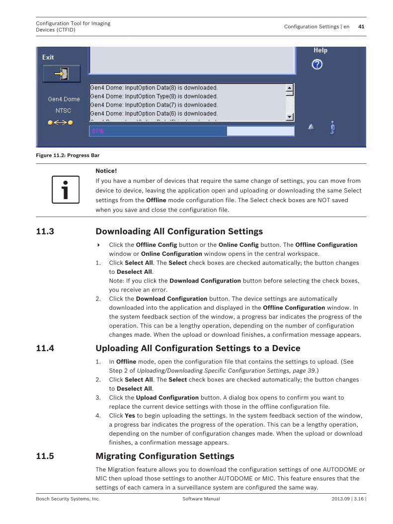
Figure 11.2: Progress Bar
Notice!
If you have a number of devices that require the same change of settings, you can move from
device to device, leaving the application open and uploading or downloading the same Select
settings from the Offline mode configuration file. The Select check boxes are NOT saved
when you save and close the configuration file.
Downloading All Configuration Settings4 Click the Offline Config button or the Online Config button. The Offline Configuration
window or Online Configuration window opens in the central workspace.1. Click Select All. The Select check boxes are checked automatically; the button changes
to Deselect All. Note: If you click the Download Configuration button before selecting the check boxes,you receive an error.
2. Click the Download Configuration button. The device settings are automaticallydownloaded into the application and displayed in the Offline Configuration window. Inthe system feedback section of the window, a progress bar indicates the progress of theoperation. This can be a lengthy operation, depending on the number of configurationchanges made. When the upload or download finishes, a confirmation message appears.
Uploading All Configuration Settings to a Device1. In Offline mode, open the configuration file that contains the settings to upload. (See
Step 2 of Uploading/Downloading Specific Configuration Settings, page 39.)2. Click Select All. The Select check boxes are checked automatically; the button changes
to Deselect All.3. Click the Upload Configuration button. A dialog box opens to confirm you want to
replace the current device settings with those in the offline configuration file.4. Click Yes to begin uploading the settings. In the system feedback section of the window,
a progress bar indicates the progress of the operation. This can be a lengthy operation,depending on the number of configuration changes made. When the upload or downloadfinishes, a confirmation message appears.
Migrating Configuration SettingsThe Migration feature allows you to download the configuration settings of one AUTODOME orMIC then upload those settings to another AUTODOME or MIC. This feature ensures that thesettings of each camera in a surveillance system are configured the same way.
11.3
11.4
11.5
Configuration Tool for ImagingDevices (CTFID)
Configuration Settings | en 41
Bosch Security Systems, Inc. Software Manual 2013.09 | 3.16 |

The CTFID saves downloaded settings in a configuration file (.ctm) on the operator’scomputer. To upload the settings stored in the .ctm file, connect another AUTODOME or MICto the computer that contains the CTFID application and has access to the configuration file.Next, use the Migration upload utility to copy the settings in the configuration file to theAUTODOME or MIC.Note: Migration is available for transferring settings only between AUTODOME or MICcameras. If you attempt to migrate settings between an AUTODOME or a MIC and anotherimaging device, or between two non-AUTODOME imaging devices, the CTFID relays a messagethat the imaging devices are incompatible.To migrate configuration settings, follow these steps:1. Connect an AUTODOME or MIC to a computer that contains the CTFID application.
Ensure that you can connect this computer to the AUTODOME or MIC that is to uploadthe configuration settings.
2. Launch the CTFID application on a computer that you can connect to differentAUTODOME or MIC Series cameras.
3. Configure the offline or online settings for the camera using the CTFID main screen.4. Click the Migration button. The Migration dialog box opens.
Figure 11.3: Migration download window
5. Select the Download option and then click OK. The CTFID collects the parameters foreach camera setting. The Save As dialog box opens.
Figure 11.4: Migration Save As dialog box
1. Navigate to the directory in which you want to store the configuration file (.ctm).
42 en | Configuration SettingsConfiguration Tool for Imaging
Devices (CTFID)
2013.09 | 3.16 | Software Manual Bosch Security Systems, Inc.

2. Type a name for the file in the File name input box and then click Save. The main CTFIDwindow reappears.
3. Disconnect the camera from the computer.4. Connect the camera that is to upload the settings to the computer.5. Launch the CTFID application and ensure that the tool connects to the camera.6. Click the Migration button. The Migration dialog box opens.
Figure 11.5: Migration upload window
7. Select the Upload option and then click OK. The Open dialog box opens.
Figure 11.6: Migration Open dialog box
8. Navigate to the directory that contains the configuration file, select the file (.ctm), andthen click Open. The CTFID software begins to upload the settings in the configurationfile to the camera.
Uploading Firmware to a DeviceTo upload firmware to a device, updates are available on the boschsecurity.com website orcall technical support for information on receiving a CD-ROM.1. Click the Upload Firmware button. The Open dialog box opens.
11.6
Configuration Tool for ImagingDevices (CTFID)
Configuration Settings | en 43
Bosch Security Systems, Inc. Software Manual 2013.09 | 3.16 |

Figure 11.7: Open dialog box
2. Navigate to the directory that contains the .img file, select the .img file, and then clickOpen. The upload process erases the existing firmware and loads the new firmware intothe device.
Uploading Firmware to a VG4/VG5 Series AUTODOMETo upload firmware to a device, updates are available on the boschsecurity.com website orcall technical support for information on receiving a CD-ROM. See the VG4/VG5 FirmwareUpdate Manual for more information about upgrading a VG4 or VG5 Series AUTODOME withthe CTFID tool.1. Click the Upload Firmware button. The Choose Service Pack Folder window opens.
11.7
44 en | Configuration SettingsConfiguration Tool for Imaging
Devices (CTFID)
2013.09 | 3.16 | Software Manual Bosch Security Systems, Inc.

Figure 11.8: Service Pack dialog box
2. Navigate to the Service Pack folder.3. Click the Select button.
Figure 11.9: Firmware upload selection dialog box
4. Select the subcomponents that you want to update.5. Click the Upload Firmware button. The upload process erases the existing firmware and
loads the new firmware into the device.
Configuration Tool for ImagingDevices (CTFID)
Configuration Settings | en 45
Bosch Security Systems, Inc. Software Manual 2013.09 | 3.16 |

Settings Tree OptionsOptions available within the settings tree will vary depending on the device selected. The tablebelow identifies available features. *Models and/or options may vary depending on theproduct. Refer to the Installation Manual or the User Manual for more details of the features ofyour camera.
Feature Description Device Default Options
2D NoiseReduction
Automatically reduces the noisein the picture. A high selection may cause blur.A lower selection improvessharpness at the cost of morenoise.
FLEXIDOME 5000 Series, DINION 5000 AN
Medium Off, Low,Medium, High
3D NoiseReduction
Automatically reduces the noisein the picture.This may cause some motion bluron exceptionally fast movingobjects immediately in front ofthe camera. This can becorrected by widening the fieldof view or lowering the selectionvalue.
FLEXIDOME 5000 Series DINION 5000 AN
Medium Off, Low,Medium, High
Action Enables the operating mode tobe selected when an alarm isactivated.
DINIONXF None None, Mode 1,Mode 2, Mode 3
Activate Button that activates the ShowTest Patterns feature
FLEXIDOME 5000 Series On, Off
Active Controls how the alarm input isactivated.Options include:None: Disabled.High: Alarm is activated when alogic high is received.Low: Alarm is activated when alogic low is received.
DINIONXF None None, High, Low
Address Allows the appropriate dome tobe operated via the numericaladdress in the control system.The address may be set locallyusing the Bilinx ConfigurationTool for Imaging Devices (CTFID)or remotely using the FastAddress function (see FastAddress).
G3A Series, NV Series, G3A Series, VG4 Series, VG5 Series,MIC550, MIC612
0000 (none)
12
46 en | Settings Tree OptionsConfiguration Tool for Imaging
Devices (CTFID)
2013.09 | 3.16 | Software Manual Bosch Security Systems, Inc.

Feature Description Device Default Options
AGC Type Controls the Automatic GainControl (AGC).
MIC612 Outdoor Outdoor, Indoor,Low Contract
Alarm Action Selects the operating mode ofthe camera when the alarm inputis active.
DINION 2X,DINION 5000 AN
None None, Mode 1,Mode 2, Mode 3,Mode 4, Mode 5,Mode 6, Mono
Alarm Input Select none to disable the alarminput. Select active-high oractive-low for the alarm inputconnector.
DINION 5000 AN None None, High, Low
Alarm Input Triggers an alarm when the inputchanges the condition.Options include:N.O. (Normally Open, drycontact).N.C. (Normally Closed, drycontact).N.C.S. (Normally ClosedSupervised contact, availableonly for alarm inputs 1 and 2).N.O.S. (Normally OpenSupervised contact, availableonly for alarm inputs 1 and 2).
VEZ Series,VG4 Series, VG5 Series, MIC550, MIC612,
N.O. VG4 Series: N.O.,N.C., N.C.S.,N.O.S. VEZ Series: N.O.,N.C.
Alarm Inputs Select none to disable the alarminput. Select active-high oractive-low for the alarm inputconnector.
DINION 2X, UPH Series None None, High, Low,Mode 1, Mode 2,Mode 3
Alarm Output VMD: Output relay closes onVMD alarms.External device: Make theoutput relay available to remotecommunication devices.Night mode active: Output relaycloses when camera is inmonochrome mode.Filter toggle: Output relay closesjust before the IR filter startsmoving and opens when videolevel has stabilized (2 to 3seconds).
DINION 2X, UPH Series,DINION 5000 AN
VMD External Device,VMD, MonoMode Active, IRFilter Toggle, Remote
Configuration Tool for ImagingDevices (CTFID)
Settings Tree Options | en 47
Bosch Security Systems, Inc. Software Manual 2013.09 | 3.16 |

Feature Description Device Default Options
ALC Level(Automatic LightControl)
Automatically adjusts the cameraaccording to the brightness ofthe scene.
DINION 2X, DINIONXF, DINIONFLEXIDOME, FLEXIDOME 2XUnity, UPH Series DINION 5000 AN
0 -15 to +15
ALC Speed(Automatic LightControl)
Controls the speed for the video-level control loop.
DINION 2X, DINIONXF,FLEXIDOME 2X,Unity, UPH Series DINION 5000 AN
Medium FastMediumSlow
Area Select Controls the quadrant that youare editing.
DINIONXF,UPH Series
1 1 to 4
Area State Actively checks for motion in apredefined area.
DINIONXF, UPH Series
On On, Off
AutoBaud Activates AutoBaud. VG4 Series, VEZ Series,MIC
On On, Off
Auto Black Boosts the video signal level toproduce a full amplitude videosignal even when the scenecontrast is less than full range(e.g. glare, fog, mist etc.). Thedarkest part of the signal is setto black and the lightest part towhite, thus increasing thecontrast.
DINIONXF,, DINIONFLEXIDOME 2X,FLEXIDOMEUnity, UPH Series
On On, Off
Auto Focus Continuously adjusts the lensautomatically to the correctfocus for the sharpest picture.Options include:Spot: Adjusts the auto focus tothe center of the image.Constant: Sets the auto focus toon for the entire image.Manual: Disables the auto focusand sets the focus for manualoperation.
G3A Series, ENV Series, VEZ Series, VG4 Series, VG5 Series,MIC550, MIC612
Manual Spot,Constant, Manual
48 en | Settings Tree OptionsConfiguration Tool for Imaging
Devices (CTFID)
2013.09 | 3.16 | Software Manual Bosch Security Systems, Inc.
Feature Description Device Default Options
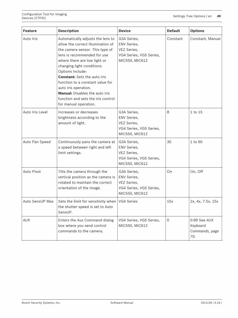
Auto Iris Automatically adjusts the lens toallow the correct illumination ofthe camera sensor. This type oflens is recommended for usewhere there are low light orchanging light conditions.Options include:Constant: Sets the auto irisfunction to a constant value forauto iris operation.Manual: Disables the auto irisfunction and sets the iris controlfor manual operation.
G3A Series, ENV Series, VEZ Series, VG4 Series, VG5 Series, MIC550, MIC612
Constant Constant, Manual
Auto Iris Level Increases or decreasesbrightness according to theamount of light.
G3A Series, ENV Series, VEZ Series, VG4 Series, VG5 Series, MIC550, MIC612
8 1 to 15
Auto Pan Speed Continuously pans the camera ata speed between right and leftlimit settings.
G3A Series, ENV Series, VEZ Series, VG4 Series, VG5 Series, MIC550, MIC612
30 1 to 60
Auto Pivot Tilts the camera through thevertical position as the camera isrotated to maintain the correctorientation of the image.
G3A Series, ENV Series, VEZ Series, VG4 Series, VG5 Series, MIC550, MIC612
On On, Off
Auto SensUP Max Sets the limit for sensitivity whenthe shutter speed is set to AutoSensUP.
VG4 Series 15x 2x, 4x, 7.5x, 15x
AUX Enters the Aux Command dialogbox where you send controlcommands to the camera.
VG4 Series, VG5 Series, MIC550, MIC612
0 0-99 See AUXKeyboardCommands, page70.
Configuration Tool for ImagingDevices (CTFID)
Settings Tree Options | en 49
Bosch Security Systems, Inc. Software Manual 2013.09 | 3.16 |

Feature Description Device Default Options
B-gain Adjusts the blue gain to optimizethe white point.
DINION 2X,DINIONXF,LTC 0485,LTC 0610,LTC 0495, LTC 0620,DINION LTC 0435,LTC 0455,FLEXIDOME VF VDC-445and XT, FLEXIDOME 2XVDC-455, Unity Dome,UPH Series,VG5 Series, MIC550, MIC612
0 -5 to +5
BacklightCompensation(BLC)
Optimizes the video level for theselected area of the image. Partsoutside this area may beunderexposed or overexposed.
G3A Series, ENV Series,VG4 Series, VEZ Series,DINIONXF, DINIONFLEXIDOME, Unity, VG5Series, MIC550, MIC612
Off On, Off
Baud Rate The speed at whichtelecommunicated data istransmitted, measured in bytesper second (Bps).
G3A Series, ENV Series,VG4 Series*, VEZ Series*,VG5 Series, MIC550Series, MIC612
9600 9600, 19200,38400, 576002400*, 4800*,9600*, 19800*,38400*, 57600*
BiPhase/Audio Turns BiPhase/Audio on and off.(Note: Audio is intended for aVG4 with an Ethernet module.Selecting audio disables Biphasecommunications.)
VG4 Series, VG5 Series,MIC550, MIC612
BiPhase BiPhase, Audio
Black Level The level of the video signal thatcorresponds to the maximumlimits of the black areas of thepicture.
DINION 2X, DINIONXF
FLEXIDOME 2X, UPHSeries
0 -55 to +55
Blanking Cuts off the electron beam in acamera pickup device or picturetube during the retrace period. Itis a signal that is composed ofrecurrent pulses at line and fieldfrequencies. It is intendedprimarily to make the retrace ona pickup device or picture tubeinvisible.
G3A Series, ENV Series,VG4 Series, VG5 Series,MIC550, MIC612
NotBlanked
Not Blanked,Blanked
50 en | Settings Tree OptionsConfiguration Tool for Imaging
Devices (CTFID)
2013.09 | 3.16 | Software Manual Bosch Security Systems, Inc.

Feature Description Device Default Options
BLC Level Electronically compensates forhigh background lighting to givedetail that would normally besilhouetted.
DINIONXF
Unity, UPH Series0 -15 to +15
BLC Mode Toggles the compensation forhigh background lighting to givedetail that would normally besilhouetted
UPH Series Off On, Off
Cable Comp Level Prevents image degradationcaused by signal losses whentransmitting video over longcable lengths.
DINION 2X, DINIONXF (not active) 0 to 15
Cable CompType / CableCompensation
Allows you to choose the coaxbeing used. If unknown, selectDefault. Note: Anything above1,000 ft. may cause a decrease inpicture quality.
DINION 2X, DINIONXF ,FLEXIDOME 5000 Series
Off Off, Default,RG59, Coax 12,Coax 6
Camera Buttons Prevents unauthorized change ofthe camera settings by disablingthe buttons.
DINION 2X, DINIONXF,DINION,FLEXIDOME, FLEXIDOME2X,Unity, UPH Series
Enabled Enabled,Disabled
DINION 5000 AN On On, Off
Camera Height The straight vertical height inrespect to the surface that youare tracking.
G3A Series, ENV Series,VG4 500 Series, VG5Series
12 ft. 8 to 100 ft.
Camera ID 16-character camera name thatmay be displayed according tothe ID position.
DINION 2X, DINIONXF,FLEXIDOME 2X, UPHSeries, DINION 5000 AN
(blankfield)
(blank field)
Camera IDPosition
Identifies the location of thecamera ID label on the outputscreen.
DINION 2X, FLEXIDOME2X DINION 5000 AN
Off OffTop LeftTop RightBottom LeftBottom Right
Camera OSD Enables or disables the cameraon-screen display informationfrom the live video image.
G3A Series, ENV Series,VG4 Series, VEZ Series,VG5 Series, MIC550,MIC612
On On, Off
Configuration Tool for ImagingDevices (CTFID)
Settings Tree Options | en 51
Bosch Security Systems, Inc. Software Manual 2013.09 | 3.16 |

Feature Description Device Default Options
Color Burst Off: The color burst in the videosignal is switched Off inmonochrome mode.On: The color burst remainsactive even in monochromemode (required by some DVRsand IP encoders).
DINION 2X, FLEXIDOME 2X, DINION 5000 AN
Off On, Off
Contrast Enhance Increases the contrast at mediumbrightness levels.Select Low for high contrastscenes.Select High for low contrastscenes (e.g. fog).
FLEXIDOME 5000 Series, DINION 5000 AN
Medium Low, Medium,High
Custom TourPeriod
Defines the length of time for acustom camera tour.
VG4 Series, VG5 Series,MIC550, MIC612
3 sec. 3-5 sec, 10, 15,20, 25, 30, 40, 50sec, 1-5 min., 10min.
Day/Night Camera is equipped with amotorized IR filter. Themechanical IR filter can beremoved in low-light or IRilluminated applications byconfiguration settings.
DINION 2X, DINION 5000ANDINIONXF LTC 0495,LTC 0610,FLEXIDOME 495,FLEXIDOME 2X,UnityDome DN VG4-162and VG4-164, DN VG4-152and VG4-154
Auto Auto, Color,Monochrome
Default Shutter Allows the shutter speed to beset to a fast speed to eliminatemotion blur and providesdetailed and clear images of fast-moving objects while there issufficient light. When light levelsfall and other adjustments havebeen exhausted, the shutterspeed reverts to the standardsetting to maintain sensitivity.
G3A Series, ENV Series,DINION 2X,DINIONXF,FLEXIDOME, FLEXIDOME 2X,Unity, UPH Series DINION 5000 AN
1/60 1/60,1/100,1/120,1/250,1/500,1/1000,1/2000,1/5000,1/10000
Digital Zoom Enables or disables the ability toenlarge or reduce the size of animage.
G3A Series, ENV Series,VG4 Series, VEZ Series,VG5 Series, MIC550,MIC612
On On, Off
Display Pattern Activates the test pattern modeto verify electronics (the outputof the digital data channel)�forthe thermal camera.
MIC612 Off Off, Color Bars
52 en | Settings Tree OptionsConfiguration Tool for Imaging
Devices (CTFID)
2013.09 | 3.16 | Software Manual Bosch Security Systems, Inc.

Feature Description Device Default Options
Display Position Controls the position for theOSD stamping.
G3A Series, ENV Series,VG4 Series, VG5 Series,MIC550, MIC612
0 0 to 16
DVR/IP Encoder On: The camera output isoptimized for connection to aDVR or IP encoder tocompensate for compressionmethods.Off: The camera output isoptimized for connection to ananalog system (matrix switcheror monitor.
DINION 2X,FLEXIDOME 2X DINION 5000 AN
Off On, Off
Dynamic NoiseReduction
Measures the noise (imageartifacts) in the picture andautomatically reduces it.
DINION 2X, DINIONXF,FLEXIDOME 2X,Unity, UPH Series
Auto Auto, Off
Dynamic Engine Off: Turns off all automatic scenedetail and enhancements (onlyrecommended for testing).XF-DYN: Extra internalprocessing is enabled for low-light applications (traffic, etc.).2X-DYN: 2X-Dynamic adds dualsensor exposure to the XF-DYNfeatures. In harsh lightingconditions pixels from eachexposure are mixed to give amore detailed image (use 2X-DYNwhen SmartBLC is not required).SmartBLC: BLC window andweighting factor areautomatically defined. Cameradynamically adjusts these forchanging light conditions.Includes all the benefits of 2X-DYN.
DINION 2X,FLEXIDOME 2X
Off,XF Dyn,2X-Dyn,(2X-DYN isavailable only inLTC 0498models)SmartBLC
Enabled Activates or deactivates AlarmRules.
Yes, No
Filtermove Activated when the filterchanges.
DINIONXF
Configuration Tool for ImagingDevices (CTFID)
Settings Tree Options | en 53
Bosch Security Systems, Inc. Software Manual 2013.09 | 3.16 |

Feature Description Device Default Options
Flat-FieldCorrection
The thermal camera uses aninternal process called flat-fieldcorrection (FFC) to improvethe�quality of the thermal videoimage displayed on the monitor.During this process, ashutter�rotates in front of theFocal Plane Array (FPA) to give auniform temperature (a flat field)to�every detector element.
MIC612
Focus Polarity Capability to reverse theoperation of the focus button onthe controller.
G3A Series, ENV Series,VG4 Series
Normal Normal, Reverse
Focus Speed Controls how fast the auto focuswill readjust when the focusbecomes blurred.
G3A Series, ENV Series,VG4 Series, VEZ Series,VG5 Series, MIC550,MIC612
2 1 to 8
Freeze Frame Holds a preposition video framewhile moving to anotherpreposition. The video isunfrozen once the new scene isreached.
VG4 Series, VEZ Series,VG5 Series, MIC550Series, MIC612
On On, Off
G-Gain Adjusts the green gain tooptimize the white point.
DINIONXF LTC 0485,LTC 0610,LTC 0495, LTC 0620, Unity, UPH Series
0 -50 to +50
Gain An increase in voltage or power,usually expressed in dB.
DINION 2X, DINIONXF,FLEXIDOME 2X, Unity, UPH Series
AGC AGC, Fixed
Gain Control Automatically sets the gain to thelowest possible value needed tomaintain a good picture.
G3A Series, ENV Series,DINION, FLEXIDOME, VEZ Series,VG4 Series, VG5 Series,MIC550, MIC612 DINION 5000 AN
On On, Off
Go to Shot Switches to a predefined shot. G3A Series, ENV Series 1 0 to 99
Heater An internal heater thatcompensates for outdoorenvironments.
FLEXIDOME,FLEXIDOME 2X
Off On, Off
Horizontal Phase Adjusts the horizontal phaseoffset.
DINION 2X, DINIONXF,DINION
0 -25 to 125
54 en | Settings Tree OptionsConfiguration Tool for Imaging
Devices (CTFID)
2013.09 | 3.16 | Software Manual Bosch Security Systems, Inc.

Feature Description Device Default Options
Illuminator Controls IR illuminators. WhenON, the camera gives a muchbetter image at low light levels.
MIC550IR Off Off, On, Auto
IlluminatorIntensity
Controls the intensity of theilluminator.
MIC550IR,DINION 5000 AN
0 0 to 15
Inactivity Selects the time period for whichthe dome must be not controlledbefore the inactivity event isexecuted.Options include:Off: Select Off when the domeshould remain in the position.Scene 1: Select Scene 1 whenthe dome should go to Scene 1.Previous Aux: Select PreviousAux when the dome should go tothe previous Aux value.
G3A Series, ENV Series,VG4 Series, VEZ Series,VG5 Series, MIC550,MIC612
Off Off, Scene 1,Previous Aux
Inactivity Period Determines the behavior of thedome when the control for domeis inactive.
G3A Series, ENV Series,VG4 Series, VEZ Series,VG5 Series, MIC550,MIC612
2 min. 3-5 sec, 10, 15,20, 25, 30, 40, 50sec, 1-5 min., 10min.
ID Border Places a border around thecamera ID on the output screen.
DINION 2X, FLEXIDOME2X DINION 5000 AN
Off On, Off
ID Position Determines the position of thecamera ID name.
DINIONXF, UPH Series Off Off, Top, Bottom
IR Contrast Optimizes the camera’s contrast.Options include:Enhanced: The camera optimizescontrast in applications with highIR illumination levels.Normal: The camera optimizescontrast in mono applicationwith visible light illumination.
DINION 2X, DINIONXF LTC0495, LTC 0610,FLEXIDOME 495,FLEXIDOME 2X, UnityDome DN VG4-162 and VG4-164,DN VG4-152 and VG4-154,DINION 5000 AN
Normal Enhanced,Normal
IR FocusCorrection
Optimizes the focus forIRlighting.
MIC550 Off On, Off, Auto
Iris Polarity Capability to reverse theoperation of the iris button onthe controller.
G3A Series, ENV Series,VG4 Series, VG5 Series,MIC550, MIC612
Normal Normal, Reverse
Iris Speed Controls how fast the iris willadjust the opening according tothe illumination of the scene.
G3A Series, ENV Series,VG4 Series, VEZ Series,VG5 Series, MIC550,MIC612
5 1 to 10
Configuration Tool for ImagingDevices (CTFID)
Settings Tree Options | en 55
Bosch Security Systems, Inc. Software Manual 2013.09 | 3.16 |

Feature Description Device Default Options
Input Selects the alarm input type. G3A Series, ENV Series Disabled Disabled, N.O.,N.C.
Input #/Output # Defines the type of physicalinput/output.
VG4 Series 1 1 to 4
Input/OutputOption
Defines a list of alarm inputs/outputs for an alarm rule.
VG4 Series, VG5 Series,MIC550, MIC612
None Alarm Inputs 1-7,Alarm Output1-3, Alarm Relay,OSD, Shot None,None Note:options varybased on theVG4configuration
In Tour Determines if the scene isincluded in a preposition tour.
G3A Series, ENV Series,VG4 Series, VG5 Series,MIC550, MIC612
No Yes, No
Language Controls the language for theOSD.
G3A Series, ENV Series,VG4 Series*,DINION 5000 AN**DINION 2X, FLEXIDOME2X,
English English, French,Spanish,German,Portuguese,Polish,Italian, Dutch,Czech*,Russian*/**
Line Lock Delay Adjusts the vertical line lockphase delay from 0° to 359°.
G3A Series, ENV Series,VG4 Series, VEZ Series,VG5 Series, MIC550,MIC612
0 0 to 359°
Low Pressure Indicates if the device ispressurized.
VG4 Series withpressurized environmentalhousing
On On
MAC Address Shows MAC address (factory set,cannot be changed).
DINION 2X, FLEXIDOME2X DINION 5000 AN
no default no selections
Mask Active Turns each of the four masks onor off.
DINION 2X, FLEXIDOME2X,DINION 5000 AN
Off On, Off
Mask Select Identifies one of the fourdifferent areas to be masked.
DINION 2X, FLEXIDOME2X,DINION 5000 AN
1 1, 2, 3, 4
56 en | Settings Tree OptionsConfiguration Tool for Imaging
Devices (CTFID)
2013.09 | 3.16 | Software Manual Bosch Security Systems, Inc.

Feature Description Device Default Options
Max Zoom Speed Controls the zoom speed. G3A Series, ENV Series,VG4 Series, VEZ Series,VG5 Series, MIC550,MIC612
Slow Slow, Medium,Fast
Max Gain Level /Max AGC
Controls the maximum value thegain can have during AGCoperation.
G3A Series, ENV Series,VG4 Series, VEZ Series,DINION 2X, DINIONXF,FLEXIDOME 2X, Unity, DINION 5000 AN
UPH Series
6620
20
1 to 61 to 60 to 30
0 to 28
Mode ID The title of the mode (10characters maximum)
DINIONXF, DINION 2X, UPHSeries, FLEXIDOME 5000Series DINION 5000 AN
24 Hour Pre-definedmodes: 24-hour,Traffic, Low light,Smart BLC, Lownoise, Vibrant
Mode ID Position Identifies the location of themode ID label on the outputscreen.
DINION 2X, FLEXIDOME2X DINION 5000 AN
Off OffTop LeftTop RightBottom RightBottom Left
Mono Burst Adjusts the color burst.Options include:On: The color burst remainsactive even when the camera isin monochrome mode.Off: The color burst in the videosignal is switched OFF when thecamera is in monochrome mode.
DINIONXF LTC 0495, LTC 0610,FLEXIDOME 495,UnityDome DN VG4-162and VG4-164, DN VG4-152 and VG4-154
Off On, Off
Motion The sensitivity number thecamera detects in an active area.
DINIONXF 0 None
Multi alarm Activates or deactivates multiplealarm settings.
MIC Series 550, 550IR Off On, Off
Night Mode Adjusts the filter operation of thecamera.Options include*:Auto: Switches the filterdepending on the sceneillumination level.On: Removes the IR filterallowing full IR sensitivity.Off: Allows the IR filter to beavailable for color modeoperation.
G3A Series, ENV Series,VG4 Series,DINION,Unity, VG5 Series,MIC550, MIC612
AutoAutoAutoAuto
Off, On, AutoOff, On, AutoOff, On, AutoOff, Forced, Auto
Configuration Tool for ImagingDevices (CTFID)
Settings Tree Options | en 57
Bosch Security Systems, Inc. Software Manual 2013.09 | 3.16 |

Feature Description Device Default Options
Night Mode Color Switches an Auto IR filter inmonochrome operation.
G3A Series, ENV Series,VG4 Series, VG5 Series,MIC550, MIC612
Off On, Off
Night ModeThreshold (IRE)
Adjusts the auto level at whichthe camera switches tomonochrome operation.
G3A Series, ENV Series,VG4 Series, VG5 Series,MIC550, MIC612
30 10 to 55
NightSense Activates the method of boostingthe sensitivity of high-resolutionBosch color cameras by 9db (afactor of 3) by combining thesignal of the color image in asingle monochrome picture.
UPH Series Auto Off, Forced, Auto
Noise ReductionLevel
Determines the level of noisereduction
MIC550 3 1 - 5
Noise ReductionMode
Activates noise reduction MIC550 On On, Off
Notch Filter Switches notch filter on or off.The notch filter can remove aMoiré pattern or color artifactscaused by closely spaced verticallines or objects (e.g. verticalsecurity bars over windows).
DINION 2X, FLEXIDOME2X
Off On, Off
Orientation Reverses the image 180 degrees(ideal when mounting upsidedown).
VG4 Series, VEZ Series,VG5 Series, MIC550,MIC612
Normal Normal, Inverted,Canted
OSD (on-screendisplay)
Text for on-screen display alarm(16 characters maximum).
G3A Series, ENV Series,DINIONXF, DINION,FLEXIDOME, Unity
On On, Off
OSD Alarm Text 17-character text displayed on amonitor when the cameratriggers a motion detectionalarm.
DINION 2X, FLEXIDOME2X, DINION 5000 AN
no default MOTIONDETECT1
OSD Brightness Adjusts the brightness for theOSD. The value 0 is for a darkdisplay and 10 is for a brightdisplay.
G3A Series, ENV Series,VG4 Series, VEZ Series
0 0 to 10
OSD Feedback DINION 2X, FLEXIDOME2X,UPH Series
On On, Off
58 en | Settings Tree OptionsConfiguration Tool for Imaging
Devices (CTFID)
2013.09 | 3.16 | Software Manual Bosch Security Systems, Inc.

Feature Description Device Default Options
Output Period Controls the length of time theoutput relay is activated.Follow: Alarm output will remainactivated for the same amount oftime the alarm input is activated.Latched: Alarm stays on until theoperator clears it.
G3A Series, ENV Series,VG4 Series, VEZ Series
Follow Follow, 1-5 sec,10, 15, 30 sec,1-5 min., 10 min.Latched
Password Controls access to lockedcommand menus.
G3A Series, ENV Series,VEZ Series, VG4 Series, VG5 Series,MIC550, MIC612
0000 (none)
Pattern Selects pattern for all masks. DINION 2X, FLEXIDOME2X,DINION 5000 AN
Black Black, Grey,White, Noise
Peak Average Adjusts the balance betweenpeak and average video control.At 0 the camera controls theaverage video level, at +15 thecamera controls the peak videolevel.
DINION 2X, DINIONXF,FLEXIDOME 2X,Unity, UPH Series DINION 5000 AN
0 -15 to +15
Peak White Invert Use Peak White Invert to reduceglare from the CRT/LCD display.Use in ANPR/LPR applications toreduce headlight glare. (Test on-site to ensure that it does benefitthe application and is notdistracting for operators of thesecurity system.)
DINION 2X, FLEXIDOME 2X, DINION 5000 AN
Off On, Off
Pre-Comp Amplifies the video gain tocompensate for long distancecable runs.
VG4 Series 1 1-10
Priority Only available in day/night automode. The higher priority asselected below as light leveldecreases.Options include:Color: Camera gives a colorimage as long as the light levelpermits.Motion: The camera avoidsmotion blur as long as the lightlevel permits.
DINION 2X, DINIONXF LTC 0495,LTC 0610,FLEXIDOME 495,FLEXIDOME 2X,UnityDome DN VG4-162and VG4-164, DN VG4-152 and VG4-154,DINION 5000 AN
Color Motion, Color
Privacy Mask Size Identifies the size, in pixels, ofthe privacy mask.
DINION 5000 AN
Configuration Tool for ImagingDevices (CTFID)
Settings Tree Options | en 59
Bosch Security Systems, Inc. Software Manual 2013.09 | 3.16 |

Feature Description Device Default Options
Privacy Mosaic Activates privacy mosaic FLEXIDOME 5000 Series,DINION 5000 AN
Off On, Off
PTZ Fixed Speed Controls the pan, tilt, zoom witha fixed speed value.
G3A Series, ENV Series,VG4 Series, VEZ Series,VG5 Series, MIC550,MIC612
4 1 to 15
R-gain Adjusts the red gain to optimizethe white point.
DINION 2X, DINIONXF LTC 0485,LTC 0610, LTC 0495,LTC 0620, DINION LTC 0435,LTC 0455,FLEXIDOME VF VDC-455and XT VDC-455, FLEXIDOME 2X, Unity, UPH Series, VG5 Series,MIC550, MIC612
0 -5 to +5
Saturation Adjusts the color saturation. Asetting of -15 leads to amonochrome image.
DINION 2X, DINIONXF LTC 0485,LTC 0610, LTC 0495,LTC 0620,FLEXIDOME 2X, Unity, UPH Series, DINION 5000 AN
0 -15 to +5
Scene # Switches between scenes. G3A Series, ENV Series,VG4 Series, VG5 Series,MIC550, MIC612
1 1 to 99
Second VideoChannel
Switches the video channelbetween Thermal camera optionand Visible (optical)camera�option.
MIC612 Thermal Thermal, Video
Sector # Switches between sector names. G3A Series, ENV Series,VG4 Series, VG5 Series,MIC550, MIC612
1 1 to 16
Select The trigger for the alarm output. DINIONXF VMD VMD, Remote
Sensitivity Determines the amount ofmotion detected in a predefinedarea required to trigger the alarmoutput.
DINION, DINION 5000 AN 1 0 to 127
60 en | Settings Tree OptionsConfiguration Tool for Imaging
Devices (CTFID)
2013.09 | 3.16 | Software Manual Bosch Security Systems, Inc.

Feature Description Device Default Options
Sensitivity Up Increases camera sensitivity byincreasing the integration timeon the CCD. This isaccomplished by integrating thesignal from a number ofconsecutive video frames toreduce signal noise.
DINIONXF,Unity, UPH Series
4x Off, 2x, 3x, 4x,5x, 6x, 7x, 8x, 9x,10x
SensUp (AutoSensUp) /Sens Up Dynamic
Increases camera sensitivity byincreasing the integration timeon the CCD. This isaccomplished by integrating thesignal from a number ofconsecutive video frames toreduce signal noise.
DINION 2X, DINION 5000 ANFLEXIDOME 2X,VG4 Series
4x15x
15x, 10x, 9x, 8x,7.5x, 7x, 6x, 5x,4x, 3x, 2x, Off
Sharpness Adjusts the sharpness of thepicture.
DINION 2X,G3A Series, ENV Series,VEZ Series,VG4 Series, VG5 Series,FLEXIDOME 2X, MIC550, MIC612, DINION 5000 AN
66
1 to 16
Sharpness Level Adjusts the sharpness of thepicture.
DINIONXF,Unity, UPH Series
0 -15 to +15
Show Camera ID Displays the camera ID on themonitor.
DINION 2X, FLEXIDOME2X
Off On, Off
Show TestPatterns
Select the desired test pattern tohelp installation and fault-finding.
DINION 2X, FLEXIDOME2X DINION 5000 AN
Common values:Color Bar 100%,Cross Hatch,UV Plane,Sawtooth 2H,Greyscale 11-Step,CheckerboardRaster, Impulse,Cross Impulse
Configuration Tool for ImagingDevices (CTFID)
Settings Tree Options | en 61
Bosch Security Systems, Inc. Software Manual 2013.09 | 3.16 |

Feature Description Device Default Options
Shutter/AGC Adjusts the electronic shutterspeed (AES). Controls the timeperiod for which light is gatheredby the collecting device.Options include*:Auto: Allows the camera toautomatically set the shutterspeed.AES: Camera maintains theselected shutter speed as long asthe light level of the scenepermits.FL: Flickerless mode avoidsinterference from light sources(recommended for use withvideo iris or DC iris lenses only).Fixed: Allows a user-definedshutter speed.
G3A Series, ENV Series,VG4 300 and 500 Series,VEZ Series,DINION 2X, DINION 5000ANDINION, DINIONXF
FLEXIDOME,FLEXIDOME 2XUnity, UPH Series
1/601/60AESAESFixedAES
Auto, 60x, 30x,15x, 7.5x, 4x, 2x,1/1,1/2, 1/4, 1/8,1/15, 1/30, 1/60,1/90, 1/100,1/125, 1/180,1/250, 1/350,1/500, 1/1000,1/1500,1/2000,1/3000,1/4000,1/6000,1/10000, Fixed,AES, FL*
Shutter Mode Turns Auto SensUP on or off. VG4 Series, VEZ Series,VG5 Series, MIC550,MIC612
AutoSensUp(VG4 Series300 and500 Series)
Auto SensUp, Off
Spot MeterDisplay
Controls the display of the spotmeter, ON or OFF, and switchesbetween degrees C and F.�TheSpot Meter must be ON beforeeither the Thermal Digitalreadout or Thermometer canbe�displayed.
MIC Series 612 Off On,Off
Stabilization An algorithm that virtuallyeliminates camera shake in boththe vertical and horizontal axes,resulting in exceptional imageclarity (see also ImageStabilization).
G3A Series, ENV Series,VG4 Series, VG5 Series,MIC550, MIC612
On On, Off
Standard TourPeriod
Changes dwell time betweenpresets during the tour.
VG4 Series 5 sec 3-5 sec, 10, 15,20, 25, 30, 40, 50sec, 1-5 min., 10min.
Sub Carrier Phase When in Genlock, adjusts the subcarrier offset in 1-degreeincrements. Only available whenin Genlock.
DINION 2X, DINIONXF,DINION
0 0 to 358
62 en | Settings Tree OptionsConfiguration Tool for Imaging
Devices (CTFID)
2013.09 | 3.16 | Software Manual Bosch Security Systems, Inc.

Feature Description Device Default Options
Switch Delay Adjusts the delay for the autolevel at which the cameraswitches to monochromeoperation.
DINION 5000 AN 5 1, 2, 3, 5, 10, 20,30, 60, 120, 240
Switch Level Adjusts the auto level at whichthe camera switches tomonochrome operation.
DINION 2X, DINIONXF LTC 0495,LTC 0610,FLEXIDOME 495,FLEXIDOME 2X, UnityDome DN VG4-162and VG4-164, DN VG4-152 and VG4-154,DINION 5000 AN
0 -15 to 15
Sync In Electronic pulses that areinserted in the video signal forthe purpose of assembling thepicture information in the correctposition.
DINION 2X, DINIONXF,UPH Series
High High,75 Ohm
Sync Mode Selects the synchronizationmethod for the camera.Options include:Crystal: Synchronizes thecamera to an internal crystal(default).Line Lock: Synchronizes thecamera to AC power andeliminates picture roll in multi-camera systems.
G3A Series, ENV Series,VG4 Series, VEZ Series,DINIONXF,DINION,FLEXIDOME,Unity
Internal
Line Lock,Crystal - I,Internal,Genlock*
Synchronization Selects the synchronizationmethod for the camera.Line Lock allows you to set aVertical Phase.
DINION 2X, DINIONXF,DINION, FLEXIDOME,Unity,DINION 5000 AN
0 Line Lock,Internal,Genlock,HV Lock*
Thermal Image Adjusts the display mode for thethermal camera. Options.
MIC612 White Hot White Hot, BlackHot, Fusion,Rainbow,Glowbow,Ironbow 1,Ironbow 2, Sepia,Color 1, Color 2,Ice Fire, Rain,Red Hot, GreenHot
Configuration Tool for ImagingDevices (CTFID)
Settings Tree Options | en 63
Bosch Security Systems, Inc. Software Manual 2013.09 | 3.16 |

Feature Description Device Default Options
Ticker Bar The ticker bar movescontinuously to show that theimage is live and not frozen orplayed back.
DINION 2X, FLEXIDOME2X DINION 5000 AN
Off On, Off
Tilt-Up Limit Sets the upper tilt limit of thecamera.
VG4 Series, VEZ Series,VG5 Series
Selected scene
Title 16-character scene name that isdisplayed when the Dome movesto a scene (must be enabled ordisabled via the Title OSD).
G3A Series, ENV Series,VG4 Series, VG5 Series,MIC550, MIC612
(blankfield)
(blank field)
Title OSD Controls how the cameradisplays the on-screen Sectorand Scene titles.Options include:Off: No on-screen titles aredisplayed.On: Always displays on-screentitles.Momentary: On-screen titlesdisplayed for a few seconds,then hidden (default).
G3A Series, ENV Series,VG4 Series, VEZ Series,VG5 Series, MIC550,MIC612
Momentary On, Off,Momentary
Tour Period Controls the waiting time untilthe dome moves to the nextscene.
G3A Series, ENV Series,VG4 Series, VEZ Series,VG5 Series, MIC550,MIC612
5 sec. 3 sec. to 10 min.
Track Alarm input option that turns thetracker on when the alarm isactivated.
G3A Series, ENV Series,VG5 600 Series
Off On, Off
Tracker Automated motion trackingsystem.
G3A Series, ENV Series,VG4 500 Series, VG5 600Series
Off On, Off
TrackerCommunication
Enables or disablescommunication between thecamera and tracker module.
G3A Series, ENV Series On On, Off
Tracker Period Controls the length of time thetracker is activated.Follow Input: Tracker remainsactivated for the same amount oftime the alarm input is activated.Latched: Tracker stays on untilthe operator clears it.
G3A Series, ENV Series,VG4 500 Series, VG5 600Series
FollowInput
Follow Input,1 sec. to 10 min.,Latched
64 en | Settings Tree OptionsConfiguration Tool for Imaging
Devices (CTFID)
2013.09 | 3.16 | Software Manual Bosch Security Systems, Inc.

Feature Description Device Default Options
Transmit Alarm input option that enables aBilinx alarm message to betransmitted to the head endequipment.
G3A Series, ENV Series Off On, Off
Trigger Alarm output option that selectsthe input to control the alarmoutput.
G3A Series, ENV Series (noneselected)
Input 1, Input 2,Input 3, Input 4
Vertical Phase Adjusts the vertical phase offset.Works in conjunction with LineLock synchronization.
DINION 2X, DINIONXF,FLEXIDOME, FLEXIDOME2X, Unity,DINION 5000 AN
0 0 to 359
VMD (VideoMotion Detection)Mode
Compares the current image witha reference image and counts thenumber of pixels that havechanged between the twoimages. An alarm is generatedwhen the number of pixelchanges exceeds a user-configured threshold.
DINION 2X, DINIONXF,DINION,FLEXIDOME 2X, UPH Series, DINION 5000 AN
Off Off, Silent, OSD
VMD Area The current area is displayedwith the upper left cornerflashing. The flashing corner ofthe image can be moved with theUp, Down, Left, Right arrowkeys. Pressing the Select keymoves the flashing cursor to theopposite corner, which can nowbe moved. Pressing Select againfreezes the area and exits thearea menu.
DINION 2X, FLEXIDOME2X
1 1 - 4
White Balance
Adjusts the color settings tomaintain the quality of the whiteareas of the image.
G3A Series, ENV Series,VG4 Series, VEZ Series
Auto ATW, Indoor,Outdoor, AWBHold, Extended,Manual
Unity,DINION 2X, DINION,FLEXIDOME 2X, UPH Series
ATW ATW, AWB Hold,Manual*
Configuration Tool for ImagingDevices (CTFID)
Settings Tree Options | en 65
Bosch Security Systems, Inc. Software Manual 2013.09 | 3.16 |

Feature Description Device Default Options
VG5 Series, MIC550, MIC612
ATW ATW, Indoor,Outdoor, AWBHold, Extended,Manual, OutdoorAuto, SodiumLamp Auto,Sodium Lamp
DINION 5000 AN ATW Indoor ATW Indoor, ATWOutdoor, AWBHold, Manual
White BalanceSpeed
Adjusts the speed of the whitebalance control loop.
DINION 2X, FLEXIDOME 2X, UPH Series,DINION 5000 AN
Medium Fast, Medium,Slow
Wide DynamicRange
Turns the wide dynamic rangefeature on or off.
VG4 300 and 500 Series Off On, Off
Wiper Starts or stops the wipermechanism.
MIC Series 550, 550IR Off Off, Start, OneShot,Intermittent
Wiper/Washer Starts or stops the wiper/washerfunction.
MIC Series 550, 550IR Off Start, Off
XF-Dynamic Optimally captures the detail inboth the high and low light areasof the scene simultaneously,maximizing the informationvisible in the picture.
DINIONXF,Unity, UPH Series
Medium Off, Low,Medium, High
Zoom Polarity Capability to reverse theoperation of the zoom button onthe controller.
G3A Series, ENV Series,VG4 Series
Normal Normal, Reverse
66 en | Settings Tree OptionsConfiguration Tool for Imaging
Devices (CTFID)
2013.09 | 3.16 | Software Manual Bosch Security Systems, Inc.

TroubleshootingThe following section details information to confirm that the CTFID software is functioningproperly.
Confirming System Connection between the PC and the DeviceWhen the CTFID software starts, the software automatically detects and connects to theattached device. The Online Configuration button is enabled when a connected device isdetected. Settings for that device should download into the software.To confirm that the device is connected to the application on the PC:1. Verify that you are in Online mode (the Online Configuration button should have a yellow
background).2. Verify that the Connection Status Indicator icon (displayed in the System Feedback area)
indicates that a connection has been made.If the application is not detecting a connected device:1. Check the device to ensure that it is working properly.2. Verify that there are no loose connections between the Configuration Tool hardware and
the PC and the Configuration Tool hardware and the device.3. Verify that the green light on the Configuration Tool hardware is illuminated.4. If necessary, disconnect the Configuration Tool hardware from the PC and reconnect it.5. Review the Status text box in the System Feedback section (lower text box in the main
screen). If the application is connected to a device, download confirmation messages aredisplayed.
13
13.1
Configuration Tool for ImagingDevices (CTFID)
Troubleshooting | en 67
Bosch Security Systems, Inc. Software Manual 2013.09 | 3.16 |
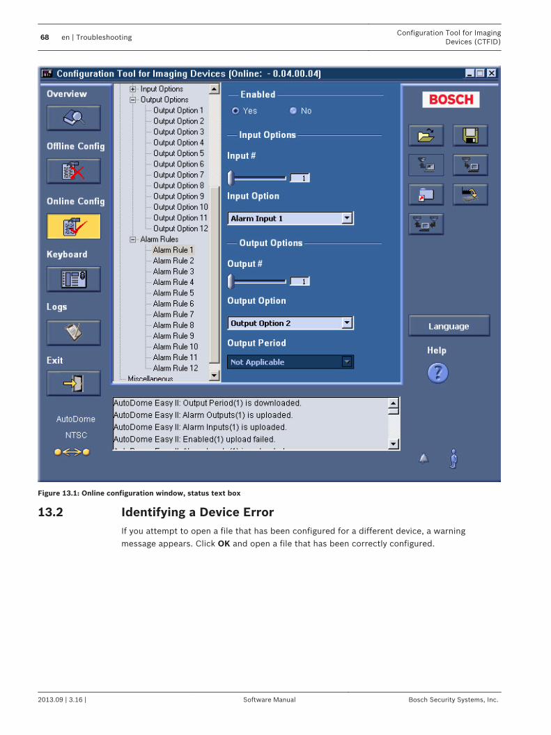
Figure 13.1: Online configuration window, status text box
Identifying a Device ErrorIf you attempt to open a file that has been configured for a different device, a warningmessage appears. Click OK and open a file that has been correctly configured.
13.2
68 en | TroubleshootingConfiguration Tool for Imaging
Devices (CTFID)
2013.09 | 3.16 | Software Manual Bosch Security Systems, Inc.

Figure 13.2: Device type error
Identifying the Version of CTFID Software1. Click the CTFID icon to the left of the software title (in the header bar).
A drop-down menu appears.
Figure 13.3: Drop-down menu from CTFID Icon
2. Scroll down and click About. The About window appears, displaying the number of theversion of the CTFID software.
Figure 13.4: About window
13.3
Configuration Tool for ImagingDevices (CTFID)
Troubleshooting | en 69
Bosch Security Systems, Inc. Software Manual 2013.09 | 3.16 |

AUX Keyboard Commands
Commands, AUTODOME
Lock
Function key
Commno.
Command Description VG4200
VG4300
VG4 500i,VG5 600
G3AENV
On/Off 1 Scan 360° Autopan without limits • • • •
On/Off 2 Autopan Autopan between limits • • • •
• On/Off 3 Iris Control Enters menu (auto, manual) • • • •
• On/Off 4 Focus Control Enters menu (spot, auto,manual)
• • • •
On/Off 7 Play Custom Pre-position Tour
Activate/Deactivate • •
On/Off 8 Play Pre-position Tour Activate/Deactivate • • • •
• On/Off 9 Inactivity Mode Enters menu (Off, Return toScene 1, Recall Previous PTZCommand)
• • • •
• On/Off 11 Auto Iris Level adjust Enters Iris Level Adjustmentmenu
• • • •
On/Off 14 Set Autopan and ScanSpeed
On—increaseOff—decrease or adjust slidebar
• • • •
On/Off 15 Set Pre-position TourPeriod (dwell)
On—increase dwellOff—decrease dwell
• • • •
• On/Off 18 AutoPivot Enable Enables/disables AutoPivot • • • •
On/Off 20 Backlight Comp Backlight Compensation • • • •
• On/Off 23 Electronic Shutter Enters Shutter Speed menu • • • •
On/Off 24 Stabilization Electronic Stabilization • •
• On/Off 35 White Balance Mode Enters White Balance menu • • • •
• On 40 Restore CameraSettings
Restores all settings to theiroriginal defaults
• • • •
• On/Off 41 Line Lock Phase Adjust On—increase Line Lock delayOff—decrease Line Lockdelay
• • • •
• On/Off 42 Sync Mode On—Line LockOff—Internal
• • • •
• On/Off 43 Auto Gain Control AGC—On, Auto, Off • • • •
• On/Off 44 Sharpness Enters Sharpness menu • • • •
• On 46 Advanced menu Enters Main Setup menu • • • •
14
14.1
70 en | AUX Keyboard CommandsConfiguration Tool for Imaging
Devices (CTFID)
2013.09 | 3.16 | Software Manual Bosch Security Systems, Inc.

Lock
Function key
Commno.
Command Description VG4200
VG4300
VG4 500i,VG5 600
G3AENV
On 47 View Factory Settings View all menu defaultsettings
• • • •
On/Off 50 Playback A, continuous Activate/Deactivate • • •
On/Off 51 Playback A, single Activate/Deactivate • • •
On/Off 52 Playback B, continuous Activate/Deactivate • • •
On/Off 53 Playback B, single Activate/Deactivate • • •
On/Off 56 Night Mode menu On, Off, Auto (Day/Nightonly)
• • • •
On/Off 57 Night Mode setting On, Off, Auto (Day/Nightonly)
• • • •
• On/Off 58 Day/Night Threshold On—menu (Day/Night only) • • • •
• On/Off 60 On Screen Display On—enableOff—disable
• • • •
• On 61 Display Adjust Adjust on-screen display • • • •
On 62 Pre-position Title menu Enters Pre-position Titlemenu
• • • •
• On 63 Zone Title menu Enters Zone Title menu • • • •
On 64 Alarm Status Enters Alarm Status menu • • •
Off 65 Alarm Acknowledge Acknowledge alarm ordeactivate physical outputs
• • •
On 66 Display software version Displays software versionnumber
• • • •
On 72 Re-initialize camera Performs camera/lens re-initialization functions
• • • •
On/Off 78 AutoTrack Turns AutoTrack on or off • •
• On 79 Camera Height Enters the Camera Heightmenu
• •
• On/Off 80 Digital Zoom Lock Turns digital zoom on and off • • •
On/Off 81 Physical output 1 On—activates outputOff—deactivates output
• •
On/Off 82 Physical Output 2 On—activates outputOff—deactivates output
• •
On/Off 83 Physical Output 3 On—activates outputOff—deactivates output
• •
On/Off 84 Physical Output 4 On—activates outputOff—deactivates output
• •
Configuration Tool for ImagingDevices (CTFID)
AUX Keyboard Commands | en 71
Bosch Security Systems, Inc. Software Manual 2013.09 | 3.16 |

Lock
Function key
Commno.
Command Description VG4200
VG4300
VG4 500i,VG5 600
G3AENV
• On/Off 86 Sector Blanking Enters Sector Blanking menu • • •
• On/Off 87 Privacy Masking Enters Privacy Masking menu • • •
On/Off 90 Command Lock/Unlock On—lock onOff—lock off
• • • •
• On/Off 91 Lens Polarity menu On—reverseOff—normal
• • • •
• On/Off 92 Lens Polarity menu On—reverseOff—normal
• • • •
• On/Off 93 Lens Polarity menu On—reverseOff—normal
• • • •
On/Off 94 Set Azimuth Zero Point On–Displays azimuth/elevation readingsOff–Hides azimuth/elevationreadings
•
On/Off 95 Display Azimuth/Elevation Readings
On–Displays azimuth/elevation readingsOff–Hides azimuth/elevationreadings
•
On/Off 96 Display CompassReadings
On–Displays compassheadingOff–Hides compass heading
•
On/Off 99 Factory P/T HomePosition
Recalibrates home position;can be used as an AlarmOutput
• • •
On/Off 100 Record A Activate/Deactivate • • •
On/Off 101 Record B Activate/Deactivate • • •
On 997 FastAddress, display Display current address • • • •
On 998 FastAddress, all units Display and program currentaddress
• • • •
On 999 FastAddress,unaddressed domes
Display and programunaddressed AutoDomes
• • • •
Set “1-99” Pre-positionprogramming
Set ##—programs a presetview
1-64 • • •
Shot “1-99” Pre-position recall Shot ##—recalls programmedpreset
1-64 • • •
Set 100 Pre-position menu Enters the Pre-position menu • • • •
Set/Shot
101 Autopan left limit Set—programs left limitShot—shows limit
• • • •
72 en | AUX Keyboard CommandsConfiguration Tool for Imaging
Devices (CTFID)
2013.09 | 3.16 | Software Manual Bosch Security Systems, Inc.

Lock
Function key
Commno.
Command Description VG4200
VG4300
VG4 500i,VG5 600
G3AENV
Set/Shot
102 Autopan right limit Set—programs right limitShot—shows limit
• • • •
Set 110 Factory P/T homeposition
Set—recalibrates homeposition
• • • •
• Set 802 Edit Password Enters the Edit Passwordmenu
• • •
• Set 899 Reset ALL Restores all settings tooriginal defaults and clearsall user-programmed settings
• • • •
Set 900 Edit Tour 1 (Standard) Enters the Standard TourScene menu
• •
Shot 900 Edit Tour 2 (Custom) Enters the Custom TourScene menu
• • • •
Set/Shot
901-999
Adds/Removes a pre-position shot from Tour1
Set ###—adds presetShot ###—removes preset
901-964
• • •
Comm no. Description
142 VLH debug values on the screen
143 WBH debug values on the screen
144 VLH/WBH debug values on screen
145 Color chart
146 White balance pixels
Notice!
Although the AUX button is active on both the FLEXIDOME and Unity Dome Series, no
additional commands are available.
Commands, MIC Series Optical Camera
Locked
FunctionKey
CommandNo.
Command Description
On/Off 1 Scan 360° / Auto Pan(Continuous)
Activates/deactivates Autopan without limits.
On/Off 2 Autopan (within Limits) Activates/deactivates Autopan between limits.
* On/Off 3 Iris Control Enters the menu (auto, manual) for iris control.
* On/Off 4 Focus Control Enters the menu (spot, auto, manual) for focuscontrol.
14.2
Configuration Tool for ImagingDevices (CTFID)
AUX Keyboard Commands | en 73
Bosch Security Systems, Inc. Software Manual 2013.09 | 3.16 |

Locked
FunctionKey
CommandNo.
Command Description
On/Off 7 Play Custom Pre-position Tour Activates/Deactivates the playback of a custom,pre-position tour.
On/Off 8 Play Pre-position Tour Activates/Deactivates the playback of a pre-position tour.
* On/Off 9 Inactivity Mode Enters the inactivity menu (Off, Return to Scene1, Recall Previous PTZ Command).
* On/Off 11 Auto Iris Level Adjust Enters the Iris Level Adjustment menu.
On/Off 14 Set Autopan and Scan Speed Enters the speed adjustment slide bar.
On/Off 15 Set Pre-position Tour Period(dwell)
Enters the dwell adjustment slide bar.
* On/Off 18 AutoPivot Enable Enables/disables AutoPivot.
On/Off 20 Backlight Comp Turns Backlight Compensation on or off.
* On/Off 23 Electronic Shutter Enters the Shutter Speed slide bar.
On/Off 24 Stabilization Turns Electronic Stabilization on or off.
On/Off 26 Wide Dynamic Range Activates/deactivates Wide Dynamic Range.
On/Off 30 White Balance Enters the White Balance menu.
* On/Off 35 Fixed White Balance Enters the White Balance menu.
* On 40 Restore Camera Settings Restores all settings to their original defaults.
* On/Off 43 Auto Gain Control Switches AGC modes (On, Auto, Off).
* On/Off 44 Aperturn Correction (Sharpness) Enters the Sharpness menu.
* On 46 Advanced Menu Enters the Main Setup menu.
On 47 View Factory Settings Displays all menu default settings.
On/Off 50 Playback A, continuous Activates/Deactivates continuous playback A.
On/Off 51 Playback A, single Activates/Deactivates single playback A.
On/Off 52 Playback B, continuous Activates/Deactivates continuous playback B.
On/Off 53 Playback B, single Activates/Deactivates single playback B.
On/Off/ 56 Night Mode Menu Enters the Night Mode menu (On, Off; Auto(Day/Night only))
On/Off 57 Night Mode Control (IR Filter In/Out)
Enables/disables Night Mode (Day = Off /Night =On).
* On/Off 58 Day/Night Threshold Enables/disables the day/nigh threshold (On–menu (Day/Night only)).
74 en | AUX Keyboard CommandsConfiguration Tool for Imaging
Devices (CTFID)
2013.09 | 3.16 | Software Manual Bosch Security Systems, Inc.

Locked
FunctionKey
CommandNo.
Command Description
On/Off 59 Night Mode Priority Motion–Activates Night Mode before slowshutter, preserving full-frame integration as lightis reduced.Color–Activates slow shutter before NightMode, preserving color longer as light isreduced.
* On/Off 60 On Screen Display On–Enables on-screen display.Off–Disables on-screen display.
* On 61 OSD Display (Adjust) Adjusts the view of the On-screen Display.
On 62 Pre-position (Scene) Title menu Enters the Pre-position Title menu.
* On 63 Zone/Sector Title Menu Enters the Zone Title menu.
On 64 Alarm Status Enters the Alarm Status menu.
Off 65 Alarm Acknowledge Acknowledges alarms or deactivates physicaloutputs.
On 66 Display Software Version Displays the number of the software version.
On/Off 67 Focus Adjust for IR Illuminators On - Automatically adjusts camera focus with IRillumination is present.
* On/Off 69 Alarm Rule Activation/Deactivation
On–Enables all alarm rules.Off–Disables all alarm rules.
On 72 Re-initialize Camera Performs camera/lens re-initialization functions.
* On/Off 80 Digital Zoom Lock Turns digital zoom on and off.
On/Off 81 Alarm Output 1Open Collector
On–Activates output.Off–Deactivates output.
On/Off 82 Alarm Output 2Open Collector
On–Activates output.Off–Deactivates output.
On/Off 83 Alarm Output 3Open Collector
On–Activates output.Off–Deactivates output.
On/Off 84 Alarm Relay On–Activates alarm relay.Off–Deactivates alarm relay.
* On/Off 86 Sector Blanking / Masking Enters / Exits the Sector Blanking menu.
* On/Off 87 Privacy Masking Enters / Exits the Privacy Masking menu.
On/Off 89 Preposition OverwriteConfirmation (toggle)
On–Isues a message that prompts for approvalto overwrite a preposition.Off–No confirmation message issued.
On/Off 90 Command Lock/Unlock On–Lock onOff–Lock off
* On/Off 91 Zoom Polarity On–ReverseOff–Normal
Configuration Tool for ImagingDevices (CTFID)
AUX Keyboard Commands | en 75
Bosch Security Systems, Inc. Software Manual 2013.09 | 3.16 |

Locked
FunctionKey
CommandNo.
Command Description
* On/Off 92 Focus Polarity On–ReverseOff–Normal
* On/Off 93 Iris Polarity On–ReverseOff–Normal
* On/Off 94 Set Azimuth Zero Point /Recalibrate Azimuth Compass
Sets the zero degree pan position.
On/Off 95 Display Azimuth/ElevationReadings
On–Displays azimuth/elevation readings.Off–Hides azimuth/elevation readings.
On/Off 96 Display Compass (Point)Readings
On–Displays compass heading.Off–Hides compass heading.
On/Off 97 Video channel (toggle) On - Switches view to thermal camera.Off - Switches view to optical camera.
On 99 Factory P/T Home Position Recalibrates home position; can be used as anAlarm Output.
On/Off 100 Record A Activates/deactivates recording A.
On/Off 101 Record B Activates/deactivates recording B.
On/Off 102 Wiper continuous Turns on/off continuos wiper mode.
On/Off 103 Wiper intermittent Activates the wiper in Intermittent mode (thewiper wipes twice, then turns off after 15seconds).
On/Off 104 Wiper one shot Activates (One shot) to wipe five times, thenturn off.
On/Off 105 Wash/Wipe Activates wash/wipe mode. Cameras moves todesignated washer preset (62), wiper startsautomatically.
On 997 FastAddress, display Display the current FastAddress of the camera.
On 998 FastAddress, all units Displays the current FastAddress of the cameraand programs all units.
On 999 FastAddress, unaddressedcameras
Displays and programs unaddressed MIC612units.
Set “1-99” Pre-position Programming Set ##–Programs a preset view.
Shot “1-99” Pre-position Recall Shot ##–Recall programmed preset.
Set 100 Pre-position Menu Enters the Pre-position menu.
Set/Shot 101 Autopan Left Limit Set–Programs left limit.Shot–Shows limit.
Set/Shot 102 Autopan Right Limit Set–Programs right limit.Shot–Shows limit.
76 en | AUX Keyboard CommandsConfiguration Tool for Imaging
Devices (CTFID)
2013.09 | 3.16 | Software Manual Bosch Security Systems, Inc.

Locked
FunctionKey
CommandNo.
Command Description
Set 110 Factory P/T Home Position Set–Recalibrate home position.
* Set 802 Edit Password Enters the Edit Password menu.
* Set 899 Reset ALL Restores all settings to original defaults andclears all user-programmed settings.
Set 900 Edit Tour 1 (Standard) Enters the Standard Tour Scene menu.
Shot 900 Edit Tour 2 (Custom) Enters the Custom Tour Scene menu.
Set/Shot 901-999 Adds/Removes a PrepositionShot from Tour 1
Set ###–Adds preset.Shot ###–Removes preset.
Commands, MIC 612 Thermal Camera
Locked
FunctionKey
CommandNo.
Command Description
On/Off 1 Scan 360° Autopan without limits.
On/Off 2 Autopan Autopan between limits.
On/Off 7 Play Custom Pre-position Tour Activates/Deactivates the playback of a custom,pre-position tour.
On/Off 8 Play Pre-position Tour Activates/Deactivates the playback of a pre-position tour.
* On/Off 18 AutoPivot Enable Enables/disables AutoPivot.
On/Off 50 Playback A, continuous Activates/Deactivates continuous playback A.
On/Off 51 Playback A, single Activates/Deactivates single playback A.
On/Off 52 Playback B, continuous Activates/Deactivates continuous playback B.
On/Off 53 Playback B, single Activates/Deactivates single playback B.
* On/Off 69 Alarm Rule Activation/Deactivation
On–Enables all alarm rules.Off–Disables all alarm rules.
* On/Off 80 Digital Zoom Lock Turns digital zoom on and off.
On/Off 81 Alarm Output 1Open Collector
On–Activates output.Off–Deactivates output.
On/Off 82 Alarm Output 2Open Collector
On–Activates output.Off–Deactivates output.
On/Off 83 Alarm Output 3Open Collector
On–Activates output.Off–Deactivates output.
On/Off 84 Alarm Output 4Relay
On–Activates output.Off–Deactivates output
On/Off 88 Proportional PTZ On–Activates Proportional PTZ.Off–Deactivates Proportional PTZ.
14.3
Configuration Tool for ImagingDevices (CTFID)
AUX Keyboard Commands | en 77
Bosch Security Systems, Inc. Software Manual 2013.09 | 3.16 |

Locked
FunctionKey
CommandNo.
Command Description
On/Off 90 Command Lock/Unlock On–Turns on the lock.Off–Turns off the lock.
On/Off 97 Video channel (toggle) On - Switches view to thermal camera.Off - Switches view to optical camera.
On 99 Factory P/T Home Position Recalibrates home position; can be used as anAlarm Output.
On/Off 100 Record A Activates/Deactivates recording A.
On/Off 101 Record B Activates/Deactivates recording B.
102 Wiper alarm Turns the wiper alarm on/off manually.
103 Wiper wipe Activates the wiper in Intermittent mode (thewiper wipes twice, then turns off after 15seconds).
104 Wiper wipe Activates (On shot) to wipe five times, then turnoff.
105 Washer/Wiper Activates the washer/wiper.
On 454 White Hot Activates thermal display mode White Hot.
Off 454 Black Hot Activates thermal display mode Black Hot.
On 455 Ice Fire Activates thermal display mode Ice Fire.
Off 455 Globow Activates thermal display mode Globow.
On 456 Ironbow 1 Activates thermal display mode Ironbow 1.
Off 456 Ironbow 2 Activates thermal display mode Ironbow 2.
On 457 Rainbow Activates thermal display mode Rainbow.
Off 457 Fusion Activates thermal display mode Fusion.
On 458 Sepia Activates thermal display mode Sepia.
Off 458 Rain Activates thermal display mode Rain.
On 459 Color 1 Activates thermal display mode Color 1.
Off 459 Color 2 Activates thermal display mode Color 2.
On 460 Red Hot Activates thermal display mode Red Hot.
Off 460 Green Hot Activates thermal display mode Green Hot.
On 463 SPOT meter display Activates the SPOT meter.
Off 463 SPOT meter display Deactivates the SPOT meter.
On 997 FastAddress, display Display the current FastAddress of the camera.
On 998 FastAddress, all units Displays the current FastAddress of the cameraand programs all units.
78 en | AUX Keyboard CommandsConfiguration Tool for Imaging
Devices (CTFID)
2013.09 | 3.16 | Software Manual Bosch Security Systems, Inc.

Locked
FunctionKey
CommandNo.
Command Description
On 999 FastAddress, unaddressedcameras
Displays and programs unaddressed MIC612units.
Set “1-99” Pre-position Programming Set ##–Programs a preset view.
Shot “1-99” Pre-position Recall Shot ##–Recall programmed preset.
Set/Shot 100 Pre-position Store/Clear Enters/ Exits pre-position menu.
Set/Shot 101 Autopan Left Limit Set–Programs left limit.Shot–Shows limit.
Set/Shot 102 Autopan Right Limit Set–Programs right limit.Shot–Shows limit.
Set/Shot 103 Lock Commands Locks commands.
Set/Shot 104 Unlock Commands Unlocks commands.
Set/Shot 106 Pre-wash position Sets the camera in pre-wash position.
Set 110 Factory P/T Home Position Recalibrates home position.
Configuration Tool for ImagingDevices (CTFID)
AUX Keyboard Commands | en 79
Bosch Security Systems, Inc. Software Manual 2013.09 | 3.16 |

IndexFfinding information in Help, 24
Hhelp, 24
Kkeyboard commands;commands
keyboard, 73, 77
Pprinting Help, 24
80 en | IndexConfiguration Tool for Imaging
Devices (CTFID)
2013.09 | 3.16 | Software Manual Bosch Security Systems, Inc.


Bosch Security Systems, Inc.850 Greenfield RoadLancaster, PA, 17601USAwww.boschsecurity.com© Bosch Security Systems, Inc., 2014


