23
CUMULATIVE ANALYSIS OF UNIFORM MECHANICAL CODE CHANGES™ 2000 to 2003
CUMULATIVE ANALYSIS OF UNIFORM MECHANICAL
CODE CHANGES™
2000 to 2003

The following pages contain comments regarding the changes to the 2000 edition of the
UNIFORM MECHANICAL CODE™ (UMC™) that were made to develop the 2003 edition
of the UMC. Some of the comments made are general in nature because the existing
language was significantly changed by amendment, deletion or replacement of existing
code language. Deleted language is shown by strikeouts and new language is underlined
(when possible).
Besides minor section changes that occurred within the book to keep section numbers
consistent and in order, two general term changes were also made throughout the entire
Code book.
1) Administrative Authority Authority Having Jurisdiction
2) Chapter 16, Part II Chapter 17, Part II
Section 203.0
Administrative Authority – is the individual official, board, depart, or agency established
and authorized by the stat, county, city, or other political subdivision created by law to
administer and enforce the provisions of the mechanical code as adopted or amended. This
definition shall include the Administrative Authority’s duly authorized representative.
Authority Having Jurisdiction — The organization, office, or individual responsible for
enforcing the requirements of a code or standard, or for approving equipment, materials,
installations, or procedures. The authority having jurisdiction shall be a federal, state, local
or other regional department or an individual such as a plumbing official; mechanical
official; labor department official; health department official; building official or others having
statutory authority. In the absence of a statutory authority, the authority having jurisdiction
may be some other responsible party. This definition shall include the Authority Having
Jurisdiction’s duly authorized representative.
Analysis: The term Administrative Authority has been deleted and replaced by the term Authority Having
Jurisdiction in all of the chapters and sections of the UMC. This change was made to make the code
consistent with language used in other codes and standards. This change also makes the term consistent
with the IAPMO rules and regulations.
Section 204.0
New definitions for Brine, Building Code, and Building Official
Brine. As determined in accordance with NFPA 30
Building Code is the building code that is adopted by this jurisdiction
Building Official. See Authority Having Jurisdiction.
Analysis: This adds new required definitions to Chapter 2. The term code has been amended to make the
code consistent with language used in other codes and standards. This change also makes the term
consistent with the IAPMO rules and regulations.
Section 205.0
New definitions for Clothes Dryer, Type 1, Clothes Dryer, Type 2, Code, and
Combustion Air.
Clothes Dryer, Type I is a factory-built package, multiply produced. Primarily used in
family living environment. May or may not be coin operated for public use.
Clothes Dryer, Type II is a factory-built package, multiply produced. Used in business with
direct intercourse of the function with the public. May or may not be operated by public or
hired attendant. May or may not be coin operated.
Code – A standard that is an extensive compilation of provisions covering broad subject
matter or that is suitable for adoption into law independently of other codes and standards.
Analysis: This adds new required definitions to Chapter 2. The term code has been amended to make the
code consistent with language used in other codes and standards. These changes also make the terms
consistent with the IAPMO rules and regulations.
Section 214.0
Labeled refers to equipment or materials to which has been attached a label, symbol, or
other identifying mark of an organization that is acceptable to the Authority Having
Jurisdiction and concerned with product evaluation, that maintains periodic inspection of
production of labeled equipment or materials, and by whose labeling the manufacturer
indicates compliance with appropriate standards or performance in a specified manner.
Analysis: This adds a new required definition to Chapter 2. The term code has been amended to make the
code consistent with language used in other codes and standards. This change also makes the terms
consistent with the IAPMO rules and regulations.
Section 221.0
New definitions for Shall, Should, Standard, and Stationary Fuel Cell Power Plant
Shall indicates a mandatory requirement.
Should indicates a recommendation or that which is advised but not required.
Standard is a document, the main text of which contains only mandatory provisions using
the word "shall" to indicate requirements and which is in a form generally suitable for
mandatory reference by another standard or code or for adoption into law. Nonmandatory
provisions shall be located in and appendix, footnote, or fine-print note and are not to be
considered a part of the requirements of a standard.
Stationary Fuel Cell Power Plant is a self-contained package or factory-matched
packages that constitute and automatically operated assembly of integrated systems for
generating useful electrical energy an recoverable energy that is permanently connected
and fixed in place.
Analysis: This adds new required definitions to Chapter 2. The term code has been amended to make the
code consistent with language used in other codes and standards. These changes also make the terms
consistent with the IAPMO rules and regulations.
Section 302.1
Chapter 16, Part II – Referenced Standards, provides guidance as to available nationally
recognized standards. A list of accepted mechanical equipment and material standards is
included in Chapter 17, Part II.
Analysis: This change was made to reflect that Chapter 16 was moved to Chapter 17 and will make it
consistent with the wording in Section 301.1.3 of the Uniform Plumbing Code.
Section 302.3
Oil-Burning Appliances. The tank, piping, and valves for appliances burning oil shall be
installed in accordance with the requirements of standards referenced in Chapter 16, Part II
NFPA 31, Standard for the Installation of Oil-Burning Equipment.
Analysis: This section was formerly Section 303.2 in the previous version of this code and has been moved
and renumbered as Section 302.3. The change in wording is to correlate the UMC and NFPA 31, Standard for
the Installation of Oil Burning Equipment. The reference to NFPA 31 already exists in Chapter 17, Part II; this
makes the source of the requirement easier for the user to identify.
Section 303.0
Type of Fuel and Fuel Connections Connecting Gas Equipment.
Deleted existing Section 303.0 language and replaced the section with text from NFPA 54,
National Fuel Gas Code, paragraphs 8.5.1 through 8.5.3.
Analysis: This change was made to correlate the UMC and NFPA 54, National Fuel Gas Code.
Section 304.6
LPG Appliances. Liquefied petroleum gas-burning appliances shall not be installed in a pit,
basement or similar location where heavier-than-air gas might collect. Appliances so fueled
shall not be installed in an above-grade under-floor space or basement unless such
location is provided with an approved means for removal of unburned gas.
Analysis: This section was deleted since there is no justification for this prohibition and NFPA has provided
statistics in the past to demonstrate that incidents involving below grade propane incidents are not greater
than those for natural gas. A similar prohibition does not exist in NFPA 54. Installations of LP-gas appliances
are common in basements in cities and states that adopt NFPA 54.
Section 308.0
Appliances installed in garages, warehouses, or other areas where they may be subjected
to mechanical damage shall be suitably guarded against such damage by being installed
behind protected barriers or by being elevated or located out of the normal path of vehicles.
Analysis: This change was made to make the code consistent with language used in other codes and
standards. This change also makes the term consistent with the IAPMO rules and regulations.
Table 3-1, Note 11
11 A central heating boiler or furnace shall be installed in accordance with the
manufacturer’s instructions and shall be installed on a floor of noncombustible construction
with noncombustible flooring and surface finish an with no combustible material against the
underside thereof, or on fire-resistive slabs or arches having no combustible material
against the underside thereof.
Exception No. 1: Appliances listed for installation on a combustible floor.
Exception No. 2: Installation on a floor protected in an approved manner. [NFPA 54:9.3.3]
Analysis: This language was extracted from NFPA 54 Section 9.3.3 and was added as Note 11 to Table 3-1.
This change was made to correlate the UMC and NFPA 54, National Fuel Gas Code.
Section 401.0
Ventilation (outdoor) air for occupants shall be designed in accordance with ANSI/ASHRAE
62-2001.
Analysis: A reference to ANSI /ASHRAE has been added. This is the standard for outdoor ventilation
requirements.
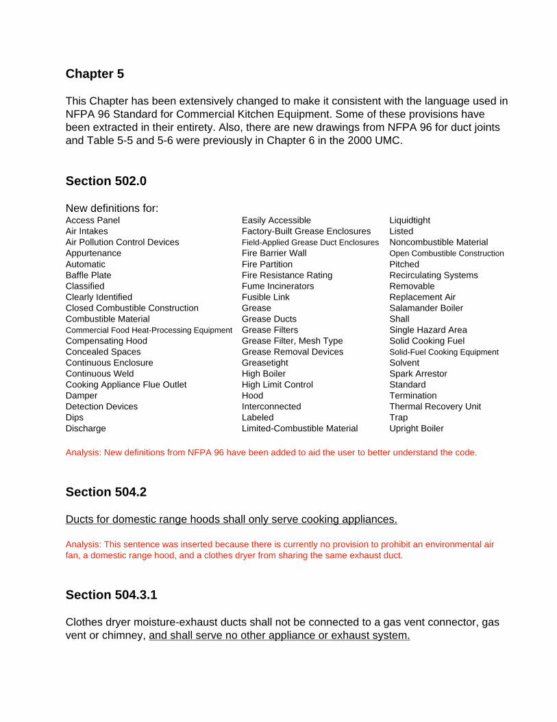
Chapter 5
This Chapter has been extensively changed to make it consistent with the language used in
NFPA 96 Standard for Commercial Kitchen Equipment. Some of these provisions have
been extracted in their entirety. Also, there are new drawings from NFPA 96 for duct joints
and Table 5-5 and 5-6 were previously in Chapter 6 in the 2000 UMC.
Section 502.0
New definitions for:Access Panel Easily Accessible Liquidtight
Air Intakes Factory-Built Grease Enclosures Listed
Air Pollution Control Devices Field-Applied Grease Duct Enclosures Noncombustible Material
Appurtenance Fire Barrier Wall Open Combustible Construction
Automatic Fire Partition Pitched
Baffle Plate Fire Resistance Rating Recirculating Systems
Classified Fume Incinerators Removable
Clearly Identified Fusible Link Replacement Air
Closed Combustible Construction Grease Salamander Boiler
Combustible Material Grease Ducts Shall
Commercial Food Heat-Processing Equipment Grease Filters Single Hazard Area
Compensating Hood Grease Filter, Mesh Type Solid Cooking Fuel
Concealed Spaces Grease Removal Devices Solid-Fuel Cooking Equipment
Continuous Enclosure Greasetight Solvent
Continuous Weld High Boiler Spark Arrestor
Cooking Appliance Flue Outlet High Limit Control Standard
Damper Hood Termination
Detection Devices Interconnected Thermal Recovery Unit
Dips Labeled Trap
Discharge Limited-Combustible Material Upright Boiler
Analysis: New definitions from NFPA 96 have been added to aid the user to better understand the code.
Section 504.2
Ducts for domestic range hoods shall only serve cooking appliances.
Analysis: This sentence was inserted because there is currently no provision to prohibit an environmental air
fan, a domestic range hood, and a clothes dryer from sharing the same exhaust duct.
Section 504.3.1
Clothes dryer moisture-exhaust ducts shall not be connected to a gas vent connector, gas
vent or chimney, and shall serve no other appliance or exhaust system.
Analysis: This sentence was inserted because there is currently no provision to prohibit an environmental air
fan, a domestic range hood, and a clothes dryer from sharing the same exhaust duct.
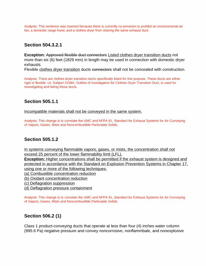
Section 504.3.2.1
Exception: Approved flexible duct connectors Listed clothes dryer transition ducts not
more than six (6) feet (1829 mm) in length may be used in connection with domestic dryer
exhausts.
Flexible clothes dryer transition ducts connectors shall not be concealed with construction.
Analysis: There are clothes dryer transition ducts specifically listed for this purpose. These ducts are either
rigid or flexible. UL Subject 2158A, Outline of Investigation for Clothes Dryer Transition Duct, is used for
investigating and listing these ducts.
Section 505.1.1
Incompatible materials shall not be conveyed in the same system.
Analysis: This change is to correlate the UMC and NFPA 91, Standard for Exhaust Systems for Air Conveying
of Vapors, Gases, Mists and Noncombustible Particulate Solids.
Section 505.1.2
In systems conveying flammable vapors, gases, or mists, the concentration shall not
exceed 25 percent of the lower flammability limit (LFL).
Exception: Higher concentrations shall be permitted if the exhaust system is designed and
protected in accordance with the Standard on Explosion Prevention Systems in Chapter 17,
using one or more of the following techniques:
(a) Combustible concentration reduction
(b) Oxidant concentration reduction
(c) Deflagration suppression
(d) Deflagration pressure containment
Analysis: This change is to correlate the UMC and NFPA 91, Standard for Exhaust Systems for Air Conveying
of Vapors, Gases, Mists and Noncombustible Particulate Solids.
Section 506.2 (1)
Class 1 product-conveying ducts that operate at less than four (4) inches water column
(995.6 Pa) negative pressure and convey noncorrosive, nonflammbale, and nonexplosive

materials at temperatures not exceeding 250°F (121°C) may be constructed in accordance
with Tables 6-1, 6-2, 6-3, 6-4, 6-5, 6-7, 6-8, or with prior approval, UMC Standard 6-2.
Analysis: With the changes occurring in Chapter 6, previously referenced tables were renumbered and
additional tables were added. This change is to reflect that the correct tables are referenced in Exception 1
for Product-Conveying Ducts.
Section 506.4
If a room or building contains a dust explosion hazard that is external to protected
equipment, as defined in 2.2.3.1 of NFPA 654, such areas shall be provided with
deflagration venting to a safe outside location.
Analysis: This change is to correlate the UMC and NFPA 654, Standard for the Prevention of Fire and Dust
Explosions from the Manufacturing, Processing, and Handling of Combustible Particulate Solids.
Section 506.5
Under Section 506.5, new sub-sections, 506.5.1 through 506.5.4, were inserted containing
language that was extracted from NFPA 91, paragraphs 2.5.1 through 2.5.4.
Analysis: This change is to correlate the UMC and NFPA 91, Standard for Exhaust Systems for Air Conveying
of Vapors, Gases, Mists and Noncombustible Particulate Solids.
Section 506.7
Duct Clearances.Deleted existing text for Section 506.7 and replaced with the following language that was
extracted from NFPA 91, paragraphs 2.6.1 through 2.6.3.8 along with any tables or figures
that are referenced within those sections.
Analysis: This change is to correlate the UMC and NFPA 91, Standard for Exhaust Systems for Air Conveying
of Vapors, Gases, Mists and Noncombustible Particulate Solids.
Part II – Commercial Hoods and Kitchen Ventilation
Section 507.0 through 517.0
The new language that was inserted in these sections has been extracted from NFPA 96.
The following are the main topics that are discussed:
Section 507.0 – General Requirements, Clearances and Alternative Methods
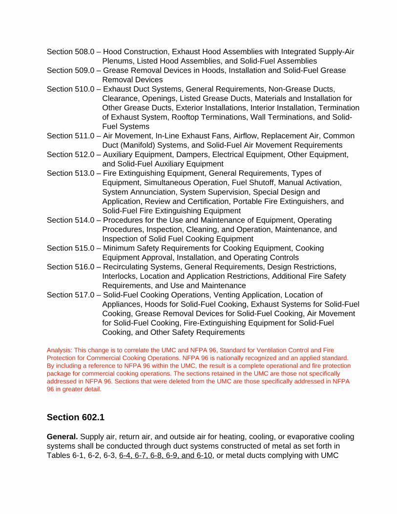
Section 508.0 – Hood Construction, Exhaust Hood Assemblies with Integrated Supply-Air
Plenums, Listed Hood Assemblies, and Solid-Fuel Assemblies
Section 509.0 – Grease Removal Devices in Hoods, Installation and Solid-Fuel Grease
Removal Devices
Section 510.0 – Exhaust Duct Systems, General Requirements, Non-Grease Ducts,
Clearance, Openings, Listed Grease Ducts, Materials and Installation for
Other Grease Ducts, Exterior Installations, Interior Installation, Termination
of Exhaust System, Rooftop Terminations, Wall Terminations, and Solid-
Fuel Systems
Section 511.0 – Air Movement, In-Line Exhaust Fans, Airflow, Replacement Air, Common
Duct (Manifold) Systems, and Solid-Fuel Air Movement Requirements
Section 512.0 – Auxiliary Equipment, Dampers, Electrical Equipment, Other Equipment,
and Solid-Fuel Auxiliary Equipment
Section 513.0 – Fire Extinguishing Equipment, General Requirements, Types of
Equipment, Simultaneous Operation, Fuel Shutoff, Manual Activation,
System Annunciation, System Supervision, Special Design and
Application, Review and Certification, Portable Fire Extinguishers, and
Solid-Fuel Fire Extinguishing Equipment
Section 514.0 – Procedures for the Use and Maintenance of Equipment, Operating
Procedures, Inspection, Cleaning, and Operation, Maintenance, and
Inspection of Solid Fuel Cooking Equipment
Section 515.0 – Minimum Safety Requirements for Cooking Equipment, Cooking
Equipment Approval, Installation, and Operating Controls
Section 516.0 – Recirculating Systems, General Requirements, Design Restrictions,
Interlocks, Location and Application Restrictions, Additional Fire Safety
Requirements, and Use and Maintenance
Section 517.0 – Solid-Fuel Cooking Operations, Venting Application, Location of
Appliances, Hoods for Solid-Fuel Cooking, Exhaust Systems for Solid-Fuel
Cooking, Grease Removal Devices for Solid-Fuel Cooking, Air Movement
for Solid-Fuel Cooking, Fire-Extinguishing Equipment for Solid-Fuel
Cooking, and Other Safety Requirements
Analysis: This change is to correlate the UMC and NFPA 96, Standard for Ventilation Control and Fire
Protection for Commercial Cooking Operations. NFPA 96 is nationally recognized and an applied standard.
By including a reference to NFPA 96 within the UMC, the result is a complete operational and fire protection
package for commercial cooking operations. The sections retained in the UMC are those not specifically
addressed in NFPA 96. Sections that were deleted from the UMC are those specifically addressed in NFPA
96 in greater detail.
Section 602.1
General. Supply air, return air, and outside air for heating, cooling, or evaporative cooling
systems shall be conducted through duct systems constructed of metal as set forth in
Tables 6-1, 6-2, 6-3, 6-4, 6-7, 6-8, 6-9, and 6-10, or metal ducts complying with UMC
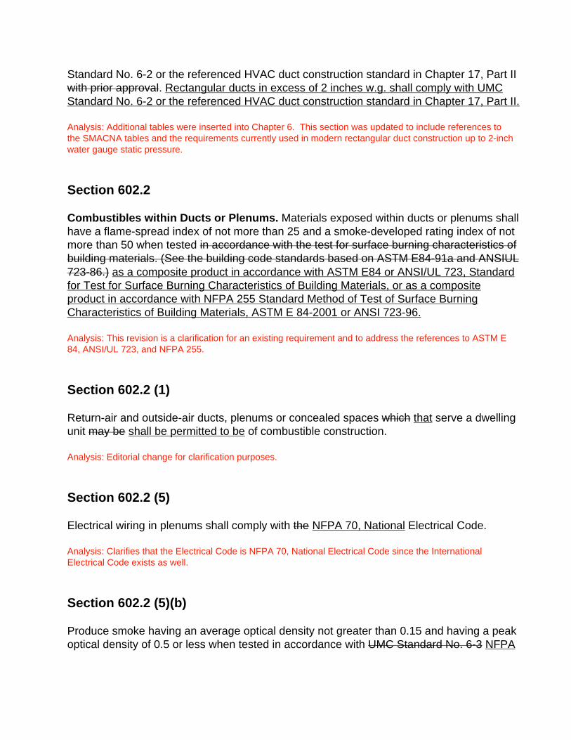
Standard No. 6-2 or the referenced HVAC duct construction standard in Chapter 17, Part II
with prior approval. Rectangular ducts in excess of 2 inches w.g. shall comply with UMC
Standard No. 6-2 or the referenced HVAC duct construction standard in Chapter 17, Part II.
Analysis: Additional tables were inserted into Chapter 6. This section was updated to include references to
the SMACNA tables and the requirements currently used in modern rectangular duct construction up to 2-inch
water gauge static pressure.
Section 602.2
Combustibles within Ducts or Plenums. Materials exposed within ducts or plenums shall
have a flame-spread index of not more than 25 and a smoke-developed rating index of not
more than 50 when tested in accordance with the test for surface burning characteristics of
building materials. (See the building code standards based on ASTM E84-91a and ANSIUL
723-86.) as a composite product in accordance with ASTM E84 or ANSI/UL 723, Standard
for Test for Surface Burning Characteristics of Building Materials, or as a composite
product in accordance with NFPA 255 Standard Method of Test of Surface Burning
Characteristics of Building Materials, ASTM E 84-2001 or ANSI 723-96.
Analysis: This revision is a clarification for an existing requirement and to address the references to ASTM E
84, ANSI/UL 723, and NFPA 255.
Section 602.2 (1)
Return-air and outside-air ducts, plenums or concealed spaces which that serve a dwelling
unit may be shall be permitted to be of combustible construction.
Analysis: Editorial change for clarification purposes.
Section 602.2 (5)
Electrical wiring in plenums shall comply with the NFPA 70, National Electrical Code.
Analysis: Clarifies that the Electrical Code is NFPA 70, National Electrical Code since the International
Electrical Code exists as well.
Section 602.2 (5)(b)
Produce smoke having an average optical density not greater than 0.15 and having a peak
optical density of 0.5 or less when tested in accordance with UMC Standard No. 6-3 NFPA
262, Standard Method of Test for Flame Travel and Smoke of Wires and Cables for Use in
Air-Handling Spaces.
Analysis: UMC Standard No. 6-3 has been removed from the 2003 UMC. NFPA 262 is the replacement
standard since cables and sprinkler pipe are referenced.
Section 602.2 (6)(b)
Produce smoke having an average optical density not greater than 0.15 and having a peak
optical density of 0.5 or less when tested in accordance with UMC Standard No. 6-3
UL 1887, Standard for Fire Test of Plastic Sprinkler Pipe for Flame and Smoke
Characteristics.
Analysis: UMC Standard No. 6-3 has been removed from the 2003 UMC. UL 1887 is the replacement
standard since nonmetallic sprinkler pipe in plenums are referenced.
Section 602.2 (7)(8)(9)
(7) Nonmetallic pneumatic tubing in plenums shall be listed and shall meet the following
requirements:
(a) Exhibit flame travel of five (5) feet (1524 mm) or less, and
(b) Produce smoke having an average optical density not greater than 0.15 and having
a peak optical density of 0.5 or less when tested in accordance with UL 1820,
Standard for Fire Test of Pneumatic Tubing for Flame and Smoke Characteristics.
(8) Loudspeakers and recessed luminaries including their assembles and accessories in
plenums shall be listed and shall meet the following requirements:
(a) Have a peak rate of heat release not greater than 100 kilowatts.
(b) Produce smoke having an average optical density not greater than 0.15 and having
a peak optical density of 0.5 or less when tested in accordance with UL 2043,
Standard for Fire Test for Heat and Visible Smoke Release of Discrete Products and
Their Accessories Installed in Air-Handling Spaces.
(9) Smoke detectors.
Analysis: These exceptions were inserted into Section 602.2 since they are allowed in NFPA 90A, Standard
for the Installation of Air-Conditioning and Ventilating Systems.
Section 602.4
Crimp joints for residential round ducts shall have a contact lap of at least 1-1/2 inch (38
mm) and shall be mechanically fastened by means of at least three sheet-metal screws
equally spaced around the joint, or an equivalent fastening method.
Joints and seams and all reinforcements for factory-made air ducts and plenums shall meet
with the conditions of prior approval in accordance with the installation instructions that
shall accompany the products. Closure systems for rigid Class 1 air ducts and plenums
shall be listed in accordance with UL 181A, Ducts and Air Connectors. and flexible Class 1
Flexible air ducts shall conform to the referenced standards for air ducts in closure systems
in Chapter 16, Part II be listed in accordance with UL 181B, Standard for Closure Systems
for Use with Flexible Air Ducts and Air Connectors.
Analysis: Residential was deleted since crimp joints are also used in commercial and industrial applications.
With the referencing of UL 181A and 181B, Class 1 was removed because UL 181 requires both Class 0 and
1 air ducts to be installed in closure systems.
Section 602.5
Metal. Every duct, plenum, or fitting of metal shall comply with Table 6-1 or 6-2 6-8.
Exceptions:(1) Ducts, plenums, and fittings for systems serving single-dwelling units may comply with
Table 6-3 6-9.
(2) Duct systems complying with UMC Standard 6-1 6-2 or the referenced HVAC duct
construction standard in Chapter 17, Part II with prior approval or duct systems
complying with UL 181, Standard for Factory-Made Air Ducts and Air Connectors.
Analysis: Besides minor editorial changes to reference the correct tables within Chapter 6 in Exception (1), in
Exception (2), the reference to UMC Standard No. 6-1 was changed because No. 6-1 is no longer part of the
2003 UMC and was replaced by UL 181.
Section 602.6
Tin. Existing tin ducts may be used when cooling coils are added to a heating system,
provided the first ten (10) feet (3048 mm) of the duct or plenum measured form the cooling
coil discharge are constructed of metal of the gage thickness set forth in Tables 6-1, 6-2 6-
8, or 6-3 6-9 of this chapter or are of approved material and construction. Tin ducts
completely enclosed in inaccessible concealed areas need not be replaced. All accessible
ducts shall be insulated to comply with Table 6-4 6-6 of this chapter.
Analysis: Minor editorial changes to reference the correct tables within Chapter 6.
Section 604.1
Metal Ducts. Ducts shall be securely fastened in place at each change of direction and as
set forth in Table 6-5 6-7. Vertical rectangular ducts and vertical round ducts shall be

supported as set forth in Table 6-5 6-7, Part I A. Riser ducts shall be held in place by
means of metal straps or angles and channels to secure the riser to the structure.
Analysis: Minor editorial changes to reference the correct tables within Chapter 6.
Section 604.2
Factory-Made Air Ducts. Approved Listed Class 0 or Class 1 factory-made air ducts may
be installed in any occupancy covered by this code.
Analysis: Listed Class 0 and Class 1 factory-made air ducts are readily available in the industry: such ducts
need to be listed to demonstrate compliance with Section 604.0.
Section 605.0
Insulation of Ducts. Supply- and return-air ducts and plenums of a heating or cooling
system shall be insulated to achieve the minimum thermal (R) value as set forth in Tables
6-4, except for ducts and plenums used exclusively for evaporative cooling systems 6-6A
and B.
Exceptions:
(A) Factory-installed plenums, casings, or ductwork furnished as a part of HVAC equipment
tested and rated in accordance with approved energy efficiency standards.
(B) Ducts or plenums located in conditioned spaces.
(C) For runouts less than 10 feet (3 m) in length to air terminal or air outlets, the rated R
value of insulation need not exceed R-3.5 (R-0.6).
(D) Backs of air outlets and outlet plenums exposed to unconditioned or indirectly
conditioned spaces with face areas exceeding 5 sq. ft. (0.5 m2) need not exceed R-2 (R-
0.4); those 5 sq. ft. (0.5 m2) or smaller need not be insulated.
(E) Ducts and plenums used exclusively for evaporative cooling system.
Analysis: These revisions make the tables 6-6A and B easier to use by directly stating the insulation R-value
required for a given application without having to read the table footnotes. The R-value selections are
consistent with both ASHRAE 90.1 and International Energy Conservation Code.
Section 605.0
Insulation applied to the exterior surface of ducts, including duct coverings and linings,
located in buildings shall have, when tested as a composite installation in the form in which
they are used, a maximum flame spread index of not more than 25 and a maximum smoke-
density not exceeding developed index of 50 when tested as a composite installation
including insulation, facing materials, tapes and adhesives as normally applied in
accordance with NFPA 255-2000, Standard Method of Test of Surface Burning
Characteristics of Building Materials or in accordance with ASTM E 84-2000a, Standard
Test Method for Surface Burning Characteristics of Building Materials or in the provisions
of UL 723-96, Standard for Test of Surface Burning Characteristics of Building Materials.
Where these products are to be applied with adhesives, they shall be tested with such
adhesives applied.
Air duct coverings and lining shall not flame, glow, smolder, or smoke when tested in
accordance with ASTM C411-97, Standard Test Method for Hot-Surface Performance of
High-Temperature Thermal Insulation, at the temperature to which they are exposed in
service. In no case shall the test temperature be below 250°F (121°C).
Factory-made air ducts and faced insulations intended for installation on the exterior
of ducts shall be legibly printed with the name of the manufacturer, the thermal resistance
(R) value at installed thickness and the flame-spread index and smoke-developed rating
index of the composite material.
Analysis: The modified language reinstates testing of duct coverings and lining as a composite installation
and eliminates referencing panels and plenums to avoid any potential confusion. The terminology adopted by
ASTM committee E5 on Fire Standards is now clear in that the terms recommended to be used are “flame
spread index” and “smoke developed index”.
Section 606.2
Ductwork shall be connected to damper sleeves or assemblies in such a way that collapse
of the ductwork will not dislodge the damper or impair its proper operation accordance with
the fire damper manufacturer’s installation instructions.
Analysis: Due to the many types of fire dampers that are now available, this change assures that the methods
for connecting ductwork to each manufacturer’s fire damper will be addressed accordingly and allow for
proper operation of the damper and enhanced safety to the building occupants.
Section 606.3
Ceiling Radiation Dampers. Ceiling radiation dampers shall comply with the standard for
ceiling radiation dampers referenced in Chapter 16 17, Part II, and shall be installed in
accordance with manufacturer’s approved installation instructions in the fire-resistive ceiling
element of floor-ceiling and roof-ceiling assemblies when required by the Building Code.
Fire dampers not meeting the temperature limitation of ceiling dampers shall not be used
as a substitute. Ceiling radiation dampers shall be labeled by an approved agency.
Analysis: The term “radiation” was inserted throughout the section to be consistent in the terminology of
“ceiling radiation dampers”.
Section 608.0
Use of Under-Floor Space as Supply Plenum for Dwelling Units.
Analysis: Additional language was inserted into the title for clarification that the requirements of this sectiononly deal with residential occupancies.
Section 608.12
The entire ground surface of the under-floor space shall be covered with a vapor barrierhaving a minimum thickness of four (4) mils (0.1016 mm) and a flame spread rating indexof 200 or less.
Analysis: The terminology adopted by ASTM committee E5 on Fire Standards is now clear in that the termrecommended to be used is “flame spread index”.
Section 609.0 (5)
Smoke detectors that are factory installed in listed air-moving equipment may be used inlieu of smoke detectors installed in the main supply-air duct served by such equipment.
Analysis: This additional exception in Section 609.0 would allow factory installed smoke detectors in the unitinstead of the SA duct.
Section 610.0
All language in Section 610.0 regarding Product-Conveying Ducts, has been removed fromChapter 6 in the 2003 UMC.
Analysis: The exact same language is addressed in Section 506.0 of Chapter 5 in the 2003 UMC.
Tables 6-1, 6-2, 6-6A, and 6-6B
Additional of dealing with duct construction for 4 and 5 foot duct lengths and minimum ductinsulation R-values were inserted into Chapter 6 of the 2003 UMC.
Analysis: Table 6-1 from the 2000 UMC has been replaced with the new SMACNA tables (6-1 and 6-2) sincethey contain the requirements currently used in modern rectangular duct construction up to 2-inch watergauge static pressure. The R-value tables were inserted for consistency with ASHRAE 90.1 and theInternational Energy Conservation Code.
Chapter 7
Table 7-1 and all previous language except Section 702.2 in Chapter 7 of the UMC 2000
has been revised and replaced by extracted language and figures from NFPA 54, Sections
8.3 and A8.3.
The following are the main topics that are discussed:
Section 701.1 – General Requirements for Combustion and Ventilation Air
Section 701.2 – Indoor Combustion Air
Section 701.3 – Indoor Opening Size and Location
Section 701.4 – Outdoor Combustion Air
Section 701.5 – Combination Indoor and Outdoor Combustion Air
Section 701.6 – Engineered Installations
Section 701.7 – Mechanical Combustion Air Supply
Section 701.8 – Mechanical Combustion Air Requirements
Section 701.9 – Louvers and Grilles
Section 701.10 – Combustion Air Ducts
Section 701.11 – Dampers Prohibited (formerly numbered 702.2 in 2000 UMC)
Analysis: This change is to correlate the UMC and NFPA 54, National Fuel Gas Code. NFPA 54 is nationally
recognized and an applied standard. By including a reference to NFPA 54 within the UMC, the result is to
ease comparison of the two documents.
Chapter 8
All previous language has been deleted and replaced with new language, figures and
tables that have been extracted from NFPA 54, Chapters 10 and 13. Some tables were
also moved from the 2000 UMC Appendix C into Chapter 8.
The following are the main topics that are discussed:
Section 801.0 – The Scope for Venting of Fuel Appliances
Section 802.0 – General Requirements for Vents
Section 802.2 – Specifications for Venting
Section 802.3 – Design and Construction
Section 802.4 – Type of Venting System to Be Used
Section 802.5 – Masonry, Metal, and Factory-Built Chimneys
Section 802.6 – Gas Vents
Section 802.7 – Single-Wall Metal Pipe
Section 802.8 – Through-the-Wall Vent Termination
Section 802.9 – Condensation Drain
Section 802.10 – Vent Connectors for Category I Gas Utilization Equipment
Section 802.11 – Vent Connectors for Category II, Category III, and Category IV Gas
Utilization Equipment
Section 802.12 – Draft Hoods and Draft Controls
Section 802.13 – Manually Operated Dampers
Section 802.14 – Automatically Operated Vent Dampers
Section 802.15 – Obstructions
Section 803.0 – Sizing of Category I Venting Systems
Section 803.2 – Additional Requirements to Multiple Appliance Vent
Analysis: This change is to correlate the UMC and NFPA 54, National Fuel Gas Code. NFPA 54 is nationally
recognized and an applied standard. By including a reference to NFPA 54 within the UMC, the result is to
ease comparison of the two documents.
Chapter 9
Some sections from this chapter have been deleted and replaced with new language,
figures and tables that have been extracted from NFPA 54, Chapter 9.
The following are the main topics that are discussed:
Section 902.0 – General Requirements
Section 903.0 – Air-Conditioning Equipment (Gas-Fired Air Conditioners and Heat Pumps)
Section 904.0 – Central Heating Boilers and Furnaces
Section 904.10 – Equipment on Roof
Section 905.0 – Clothes Dryers
Section 906.0 – Conversion Burners
Section 907.0 – Decorative Appliances for Installation in Vented Fireplaces
Section 908.0 – Gas Fireplaces, Vented
Section 909.0 – Non-Recirculating Direct Gas-Fired Industrial Air Heaters
Section 910.0 – Recirculating Direct Gas-Fired Industrial Air Heaters
Section 911.0 – Duct Furnaces
Section 912.0 – Floor Furnaces
Section 913.0 – Food Service Equipment, Floor Mounted
Section 914.0 – Food Service Equipment, Counter Appliances
Section 915.0 – Hot Plates and Laundry Stoves
Section 916.0 – Household Cooking Appliance
Section 917.0 – Illuminating Appliances
Section 918.0 – Incinerators, Commercial-Industrial
Section 919.0 – Infrared Heaters
Section 920.0 – Open-Top Broiler Units (formerly numbered 918.0 in 2000 UMC)
Section 921.0 – Outdoor Cooking Appliances
Section 922.0 – Pool Heaters
Section 923.0 – Refrigerators
Section 924.0 – Room Heaters (formerly numbered 916.0 in 2000 UMC)
Section 925.0 – Stationary Gas Engines
Section 926.0 – Gas-Fired Toilets
Section 927.0 – Unit Heaters
Section 928.0 – Wall Furnaces
Section 929.0 – Appliances for Installation in Manufactured
Section 930.0 – Small Ceramic Kilns (formerly numbered 920.0 in 2000 UMC)

Analysis: This change is to correlate the UMC and NFPA 54, National Fuel Gas Code. NFPA 54 is nationally
recognized and an applied standard. By including a reference to NFPA 54 within the UMC, the result is to
ease comparison of the two documents.
Chapter 1020.0
Fuel Piping, Tanks, and Valves. Fuel piping shall conform to Chapter 16 Part II,
Referenced Standards - Tanks, piping, and valves for oil-burning appliances, Chapter 2
and 3 of shall be installed in accordance with NFPA 31-1978, Standard for the Installation
of Oil-Burning Equipment.
Analysis: This change is to correlate the UMC and NFPA 31, Standard for Installation of Oil-Burning
Equipment.
Section 1106.1
Human Comfort. Cooling systems used for human comfort shall comply with the return-air
and outside-air provisions for furnaces in Section 906.0 904.7 and 904.8 of this code.
Cooling equipment used for human comfort in dwelling units shall be sized to satisfy the
calculated loads determined in accordance with the reference standards in Chapter 17,
Part II or other approved methods.
Analysis: The existing text in Section 906.0 was retained because it provides guidance on return air and
outside air for cooling systems. The new requirements were limited to residential.
Section 1106.3 (4)
Cooling or refrigeration equipment, using Group A1 and B1 refrigerants or brine, located on
a roof or on an exterior wall of a building may be provided access as for furnaces in Section
910.0 904.10 of this code.
Analysis: With all the new language that was changed in Chapter 9, this change is to reflect the correct
referenced section for equipment on roofs.
Section 1107.1.2
Exceptions:
1. Systems containing less than thirty-five (35) pounds (16 kg) of refrigerant R-717 and
located in an approved exterior location.
2. Direct and indirect-fired lithium bromide absorption systems using water as the
refrigerant.

Refrigeration machinery rooms shall house all refrigerant-containing portions of the
system other than the piping and evaporators permitted by Section 1105.3, discharge
piping required of this chapter, and cooling towers regulated by this chapter, Part II, and
their essential piping.
Analysis: The 1997 UMC included provisions that required a machinery room for equipment with refrigerants
other than A1. Since Section 1107.1 requires a machinery room for A1 refrigerants, when equipment exceeds
100 HP, it is important to require protection for equipment containing refrigerants other than A1, as they are
either toxic, flammable or both. The deleted language has been moved to Section 1107.1.4 in the 2003 UMC.
Section 1107.1.4
The system contains other than a Group A1 refrigerant.
Exceptions:
(1) Lithium bromide absorption systems using water as the refrigerant.
(2) Ammonia-water absorption unit systems installed outdoors, provided that the quantity of
refrigerant in a single system does not exceed Table 11-1 amounts and the discharge is
shielded and dispersed.
(3) Systems containing less than 300 pounds (136kg) of refrigerant R-123 and located in an
approved exterior location.
(4) Systems containing less than 35 pounds (16 kg) of refrigerant R-717 and located in an
approved exterior location.
Refrigeration machinery rooms shall house all refrigerant-containing portions of the
system other than the piping and evaporators permitted by Section 1105.3, discharge
piping required of this chapter, and cooling towers regulated by this chapter, Part II, and
their essential piping.
Analysis: The 1997 UMC included provisions that required a machinery room for equipment with refrigerants
other than A1. Since Section 1107.1.2 requires a machinery room for A1 refrigerants, when equipment
exceeds 100 HP, it is more important to require protection for equipment containing refrigerants other than
A1, as they are either more toxic, more flammable or both. Exception (4) and the proceeding paragraph came
from Section 1107.1.2 in the 2000 UMC
Section 1110.3
Ferrous Materials. Iron and steel refrigeration piping, valves, fittings and related parts shall
be approved for the intended use. Pipe more than two (2) inches (50 mm) iron pipe size
shall be electric-resistance welded or seamless pipe. (See UMC Standard 11-3 in Appendix
A.)
Analysis: UMC Standard No. 11-3 has been removed from the 2003 UMC. This was an outdated transcribed
standard and was replaced by current standards referenced to make and keep the UMC current.
Section 1111.8
Identification. Piping shall be meet the reference standard for identified in accordance with
UMC Standard No. 11-2. The type of refrigerant, function and pressure shall be indicated.
Analysis: UMC Standard No. 11-2 has been removed from the 2003 UMC. This was an outdated transcribed
standard and was replaced by current standards referenced to make and keep the UMC current.
Section 1112.4
Stop valves shall be identified by tagging in accordance with UMC Standard No. 11-2 the
referenced standard for identification. A valve chart shall be mounted under glass at an
approved location near the principal entrance to a refrigeration machinery room.
Analysis: UMC Standard No. 11-2 has been removed from the 2003 UMC. This was an outdated transcribed
standard and was replaced by current standards referenced to make and keep the UMC current.
Table 11-1
Additional refrigerant data was inserted into Table 11-1. This data was reprint with the
permission from the American Society of Heating, Refrigerant, and Air-Conditioning
Engineering.
Analysis: Updated Table 11-1 to the current ASHRAE standard.
Section 1201.4.1.3
Insulation. Covering and insulation used for hot water pipes shall be of material suitable
for the operating temperature of the system. The insulation, jackets, and lap-seal
adhesives, including pipe coverings and linings, shall be tested as a composite product
installation and shall have a flame-spread index of not more than 25 and a smoke-
developed rating index of not more than 50 when tested in accordance with building code
standards NFPA 255-2000, Standard Method of Test of Surface Burning Characteristics of
Building Materials; in accordance with ASTM E 84-2000a, Standard Test Method for
Surface Burning Characteristics of Building Materials; or in accordance with the provisions
of UL 723-96, Standard for test of Surface Burning Characteristics of Building Materials.
Insulation coverings and linings shall not flame, glow, smolder, or smoke when tested in
accordance with ASTM C 411-97, Standard Test Method for Hot-Surface Performance of
High-Temperature Thermal Insulation, at the temperature to which they are exposed in
service. In no case shall the test temperature be below 250°F (121°C).
Analysis: These changes are consistent with proposals made to NFPA 90A and to the IMC, and with changes
to Section 602.2 and 605.0 in the UMC. This revision is a clarification for an existing requirement and to
address the references to ASTM E 84, ANSI/UL 723, ASTM C 411 and NFPA 255. The terminology adopted
by ASTM committee E5 on Fire Standards is now clear in that the terms recommended to be used are “flame
spread index” and “smoke developed index”.
Section 1201.5
Those portions of the hot water piping systems in which the continuous pressure
temperature relationship does not exceed the following shall be permitted to be constructed
of cross-linked polyethylene/aluminum/cross-linked polyethylene (PEX-AL-PEX) piping
conforming to specification ASTM F1281.
Additional PEX-AL-PEX requirements are mentioned within sub-sections of 1201.5. Refer
to 2003 UMC for detail of these requirements.
Analysis: Requirements for PEX-AL-PEX were inserted into Chapter 12. This material has been demonstrated
to be suitable for the application mentioned.
Chapter 13
All previous language has been deleted and replaced with new language, figures and
tables that have been extracted from Chapters 1, 5, 6, 7, 8, and 12 in NFPA 54, Appendix
B in the 2000 UMC, and sections in NFPA 501A.
The following are the main topics that are discussed:
Part I – Fuel Piping
1303.1 – Appliance Fuel Connector
1303.2 – Fuel Gas
1303.3 – Gas Piping
1304.0 – Inspection of gas piping
1305.0 – Certification of Inspection
1306.0 – Authority to Render Gas Service
1307.0 – Authority to Disconnect
1308.0 – Temporary Use of Gas
1309.0 – Gas Piping System Design, Materials, and Components
1309.3 – Interconnections Between Gas Piping Systems
1309.4 – Sizing of Gas Piping Systems
1309.5 – Acceptable Piping Materials and Joining Methods
1309.6 – Gas Meters
1309.7 – Gas Pressure Regulators
1310.0 – Venting of Gas Appliance Pressure Regulators
1311.0 – Gas Piping Installation
1311.2 – Installation of Piping
1311.3.1 – Concealed Piping in Building
1311.6 – Drips and Sediment Traps
1311.7 – Outlets Fittings and Piping
1311.9 – Manual Gas Shutoff Valves
1311.11 – Systems Containing Gas-Air Mixtures Outside the Flammable Range
1311.12 – Systems Containing Flammable Gas-Air Mixtures
1311.13 – Electrical Bonding and Grounding
1311.16 – Pipe Sizing Methods
1312.0 – Equipment Connections to Building Piping
1313.0 – LP-Gas Facilities and Piping
1314.0 – Pressure Testing and Inspection
Part II – Fuel Supply: Manufactured/Mobile Home Parks and Recreational Vehicle Parks
1320.0 – Single and Multiple Manufactured Homesite Fuel Supply Systems
1325.0 – Manufactured Home Community LP-Gas Supply Systems
1334.0 – Manufactured Home Accessory Building Fuel Supply Systems
1335.0 – Community Building Fuel Supply Systems in Manufactured Home Communities
1336.0 – Recreational Vehicle Park Fuel Gas Equipment and Installations
Analysis: This change is to correlate the UMC and NFPA 54, National Fuel Gas Code. NFPA 54 is nationally
recognized and an applied standard. By including a reference to NFPA 54 within the UMC, the result is to
ease comparison of the two documents. These are three important areas that changed: Fuel gas piping
systems are limited to 5 psi, the specific prohibition against liquefied petroleum appliances in a pit or
basement was removed, and CSST fuel piping systems were added to the code.
Chapter 14
No change
Chapter 15
No change
Section 1601.0
Scope. Stationary fuel cell power plants shall be tested in accordance with ANSI Z21.83,
American National Standard/Canadian Gas Association Standard for Fuel Cell Power
Plants, and shall be installed in accordance with NFPA 853, Standard for the Installation of
Stationary Fuel Cell Power Plants and the manufacturer’s installation instructions.
Analysis: This is a new chapter, which references ANSI Z 21.83 (Standard for Fuel Cell Power Plants)
Chapter 17
Chapter 16 of the 2000 UMC has been moved to Chapter 17 in the 2003 UMC.
In Part I, only UMC Standards No. 2-2, 6-2, and 6-5 have been retained. The remaining
standards were deleted.
In Part II, the standards are listed by product category and promulgating agency.
Analysis: The format of the standards was completely redone by the Standards Task Group to be more user
friendly.
Appendix A, Standard No. 6-2
See Section 506.2, 602.1, and 602.5 of the Uniform Mechanical Code
Analysis: Two additional sections reference Standard No. 6-2 in the 2003 UMC.
Appendix B
All language from Appendix B, Chapter 15 has been deleted and replaced with extracted
language from NFPA 54, Chapter 11.
Analysis: This change is to correlate the UMC and NFPA 54, National Fuel Gas Code. NFPA 54 is nationally
recognized and an applied standard. By including a reference to NFPA 54 within the UMC, the result is to
ease comparison of the two documents.
Appendix C
All language from Appendix C has been moved into the body of code in the 2003 version.
Chapter 16 in Appendix B of the 2000 UMC has been moved into Appendix C of the 2003
UMC.
Analysis: Reformatting of the 2003 UMC to be more user friendly.


