International Journal of Emerging Technologies and Engineering (IJETE) Volume 2 Issue 8, August 2015, ISSN 2348–8050 125 www.ijete.org Current mode Controller Design for Single Phase grid connected Inverter Using Proportional Resonant Control Strategy VINAY SHARMA RAVINDRA KUMAR M. Tech. (ED&T) Department of ED&T NIELIT, GOR AKHPUR, UP, India NISHANT TRIPATHI (Deputy Director) Department of ED&T NIELIT, GOR AKHPUR, UP, India Abstract This paper presents the design of controller based on propo rtiona l resonant stra tegy for singl e-pha se grid connected inverter. The control design is carried out using Sisotool, which is provided in Matlab. By using this tool, users can examine the effects of changing the gain control values to system's transient response and stability, simultaneously. Hence, simplify and speed up the control design process. To evaluate the performance of the designed controller, the inverter is simulated under several types of load disturbances. From the result, it is shown that the designed controller exhibits a good transient response i.e. fast rising and settling time with small overshoot when subjected to step load disturbance. K e ywords–grid - c onnec ted inv erter, fi lm capacito r, PR controller, transient and steady state response. I.INTRODUCTION In recent years, distributed generation has been put on the agenda, distributed generation has the merits of less pollution, high reliability, high energy efficiency and installation flexibility, it can solve many potential problems of the large scale centraliz ed power effectively, however, electricity produced by distributed power generatio n can’t supply to AC load directly, grid- connected interface equipment must be inserted 1 . Power inverter is an important part of many DC to AC conversion equipments such as uninterruptable power supply (UPS), induction motor drive and automatic voltage regulator (AVR) systems. In these systems, it is the major requirement for the power inverter to be capable of producing and maintaining a stable and clean sinusoidal output voltage waveform regardless of the type of load connected to it. The main key to successfully maintain this ability is to have a feedback controller [1]. Currently, grid-connected inverter generally use control strategy of the output current control, nowadays, the most commonly used method have PID control and so on. It has the merits of good control performance, robustness, and simple algorithm, clear physical meanings of parameters, easy to implement and high reliability, so it is widely applied in industry field as yet but convention al control can't reach perfect control effects for sine reference current, because this method has relatively more rise and settling time. In order to settle this problem, PR controller is designed in this paper. II.MODEL OF SINGLE PHASE GRID CONNECTED INVERTER Figure 1, shows the equivalent circuit of a single- phase full bridge inverter with connected load.In this study, control based on the proportional resonant strategy theory is presented. Figure 1: Full bridge single phase PV inverter A full bridge configuration with SPWM unipolar voltage switching scheme is used as the switching circuit of the inverter. By selecting the full bridge configuration, the minimal allowed DC-link voltage can be set to be the peak value of the AC grid voltage (plus margins). Thus, power MOSFETs, instead of higher voltage IGBTs, can be used as the switching devices which enable use of a high switching frequency (> 20 kHz)without introductio n of excessiv e switching loss.
Transcript
7/24/2019 Current mode Controller Design for Single Phase grid connected Inverter Using Proportional Resonant Control Strategy
International Journal of Emerging Technologies and Engineering (IJETE)Volume 2 Issue 8, August 2015, ISSN 2348 – 8050
125
www.ijete.org
Current mode Controller Design for Single Phase grid connected Inverter
Using Proportional Resonant Control Strategy
VINAY SHARMA
RAVINDRA KUMAR
M. Tech. (ED&T)Department of ED&T
NIELIT, GORAKHPUR, UP, India
NISHANT TRIPATHI
(Deputy Director)Department of ED&T
NIELIT, GORAKHPUR, UP, India
AbstractThis paper presents the design of controller based on
proportional resonant strategy for single-phase gridconnected inverter. The control design is carried out usingSisotool, which is provided in Matlab. By using this tool,
users can examine the effects of changing the gain controlvalues to system's transient response and stability,simultaneously. Hence, simplify and speed up the control
design process. To evaluate the performance of thedesigned controller, the inverter is simulated under severaltypes of load disturbances. From the result, it is shown that
the designed controller exhibits a good transient responsei.e. fast rising and settling time with small overshoot
when subjected to step load disturbance.
Keywords – grid - connected inverter, film capacitor, PR
controller, transient and steady state response.
I. INTRODUCTION
In recent years, distributed generation has been puton the agenda, distributed generation has the merits of
less pollution, high reliability, high energy efficiencyand installation flexibility, it can solve many potential
problems of the large scale centralized powereffectively, however, electricity produced by distributed
power generation can’t supply to AC load directly, grid-
connected interface equipment must be inserted1.Power inverter is an important part of many DC to
AC conversion equipments such as uninterruptable power supply (UPS), induction motor drive andautomatic voltage regulator (AVR) systems. In thesesystems, it is the major requirement for the powerinverter to be capable of producing and maintaining a
stable and clean sinusoidal output voltage waveformregardless of the type of load connected to it. The mainkey to successfully maintain this ability is to have afeedback controller [1].
Currently, grid-connected inverter generally usecontrol strategy of the output current control, nowadays,
the most commonly used method have PID control andso on. It has the merits of good control performance,robustness, and simple algorithm, clear physical
meanings of parameters, easy to implement and highreliability, so it is widely applied in industry field as yet
but conventional control can't reach perfect controleffects for sine reference current, because this methodhas relatively more rise and settling time. In order tosettle this problem, PR controller is designed in this
paper.
II. MODEL OF SINGLE PHASE GRID
CONNECTED INVERTER
Figure 1, shows the equivalent circuit of a single-
phase full bridge inverter with connected load. In thisstudy, control based on the proportional resonantstrategy theory is presented.
Figure 1: Full bridge single phase PV inverter
A full bridge configuration with SPWM unipolar
voltage switching scheme is used as the switching circuitof the inverter. By selecting the full bridgeconfiguration, the minimal allowed DC-link voltage can
be set to be the peak value of the AC grid voltage (plusmargins). Thus, power MOSFETs, instead of higher
voltage IGBTs, can be used as the switching deviceswhich enable use of a high switching frequency (> 20kHz) without introduction of excessive switching loss.
International Journal of Emerging Technologies and Engineering (IJETE)Volume 2 Issue 8, August 2015, ISSN 2348 – 8050
126
www.ijete.org
A.
Output Filter Design
A third order LCL filter, Figure 2, was used to meetthe aforementioned harmonic reduction target. Aswitching frequency of 30 kHz was selected based onconsiderations for the filter size and the practicalimplementation of the digital controller.
Figure 2: Output LCL filter of the inverter
vt (t) stands for the terminal voltage, whichconsists of a fundamental component and higher
order harmonics components. Solving the grid
current in Laplace domain using superpositionyields the following transfer functions:
(2)
Consider the equation (1) in the output filterdesign the terminal voltage vt (t) contains a
fundamental component and higher frequencycomponents which could result in higher frequencydistortions on the grid current i g (t). Therefore,
Equation (1) is used as the output filter transfer
function as:
The RMS value of the higher order frequencycomponents of vt (t) can be calculated as:
Combining equation (3) and (4), the RMS value ofthe harmonic current can be expressed as:
Remember that cannot exceed 0.3% of
the rated current of the inverter. Therefore, given the
RMS value of the rated grid current the
following relationship can be derived:
Figure 3: Magnitude plot of the output filter transferfunction H f (s)
Rewrite for then:
For worst case k(h) at 2m f -1 is 0.37.
With the transfer function of the filter derived in
equation (3), the generic magnitude plot of H f (s) can be
drawn as shown in figure 3 at =376614, the magnitude
of H f (j376614) from the magnitude plot of H f (j )
should at most be -70dB. This is the guideline o
choosing the values for Li, L g , C f and Rd . Finally, the
LCL filter components are chosen following thisguideline and the values of each component are shownin Table 1.
Table 1: Output filter parameters and their chosen values
Li L g c f Rd
300 H 100 H 30 F 1.5Ω
III. CONTROL SYSTEM DESIGN
The design of the controller for the inverter can bedivided into two parts: 1) current controller, and 2) DCvoltage controller.
A.
CURRENT CONTROLLER
A single phase feedback current loop is used toregulate the grid current. A proportional resonant (PR)control strategy is used as a compensator to track asinusoidal current reference signal.
International Journal of Emerging Technologies and Engineering (IJETE)Volume 2 Issue 8, August 2015, ISSN 2348 – 8050
129
www.ijete.org
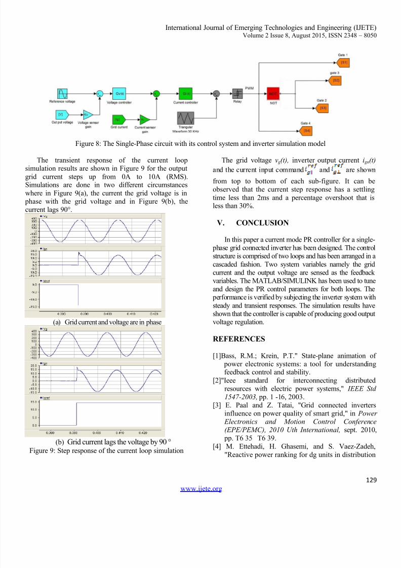
Figure 8: The Single-Phase circuit with its control system and inverter simulation model
The transient response of the current loopsimulation results are shown in Figure 9 for the output
grid current steps up from 0A to 10A (RMS).Simulations are done in two different circumstances
where in Figure 9(a), the current the grid voltage is in
phase with the grid voltage and in Figure 9(b), thecurrent lags 90°.
(a)
Grid current and voltage are in phase
(b) Grid current lags the voltage by 90 °
Figure 9: Step response of the current loop simulation
The grid voltage v g (t), inverter output current i gn(t)
and the current input command and are shown
from top to bottom of each sub-figure. It can beobserved that the current step response has a settling
time less than 2ms and a percentage overshoot that isless than 30%.
V. CONCLUSION
In this paper a current mode PR controller for a single- phase grid connected inverter has been designed. The controlstructure is comprised of two loops and has been arranged in a
cascaded fashion. Two system variables namely the gridcurrent and the output voltage are sensed as the feedbackvariables. The MATLAB/SIMULINK has been used to tuneand design the PR control parameters for both loops. The
performance is verified by subjecting the inverter system withsteady and transient responses. The simulation results haveshown that the controller is capable of producing good outputvoltage regulation.
REFERENCES
[1]Bass, R.M.; Krein, P.T." State-plane animation of power electronic systems: a tool for understandingfeedback control and stability.
[2]"Ieee standard for interconnecting distributedresources with electric power systems," IEEE Std
1547-2003, pp. 1 -16, 2003.[3] E. Paal and Z. Tatai, "Grid connected inverters
influence on power quality of smart grid," in Power Electronics and Motion Control Conference(EPE/PEMC), 2010 Uth International, sept. 2010
pp. T6 35 T6 39.[4] M. Ettehadi, H. Ghasemi, and S. Vaez-Zadeh,
"Reactive power ranking for dg units in distribution
systems," Master's thesis, University of Toronto,Toronto, 2010.
[8] R. Erickson and A. Rogers, "A microinverter for
building-integrated photovoltaics," in Applied Power Electronics Conference and Exposition,2009. APEC 2009. Twenty-Fourth Annual IEEE,feb. 2009, pp. 911 917.
[9] “Design of a Current Mode PI Controller for a Single- phase PWM Inverter” 2011 IEEE Applied Power
Design and TechnologyInstitute- National Institute of Electronics andInformation Technology (NIELIT) Gorakhpur Centre,MMM University of Technology Campus, Gorakhpur- 273010