+ All Categories
Home > Documents > Current monitoring relays CM-SRS - Farnell element14 CM-SRS.1 is an electronic current monitoring...

Current monitoring relays CM-SRS - Farnell element14 CM-SRS.1 is an electronic current monitoring...

Date post: 25-May-2018
Category:
Upload: ngodiep
View: 227 times
Download: 0 times
Share this document with a friend
12
2CDC 251 055 V0011 Data sheet Current monitoring relays CM-SRS.1 For single-phase AC/DC currents The CM-SRS.1 is an electronic current monitoring relay that protects single-phase mains (DC or AC) from over- and undercurrent from 3 mA to 15 A. All devices are available with two different terminal versions. You can choose between the proven screw connection technology (double-chamber cage connection terminals) and the completely tool-free Easy Connect Technology (Push-in terminals). Characteristics Monitoring of DC and AC currents (3 mA to 15 A) TRMS measuring principle One device includes 3 measuring ranges Over- or undercurrent monitoring configurable Hysteresis adjustable (3-30 %) 3 control supply voltage versions Precise adjustment by front-face operating controls Screw connection technology or Easy Connect Technology available Housing material for highest fire protection classification UL 94 V-0 Tool-free mounting on DIN rail as well as demounting 1 c/o (SPDT) contact 22.5 mm (0.89 in) width 3 LEDs for status indication Approvals A UL 508, CAN/CSA C22.2 No.14 C GL (pending) D GOST K CB Scheme E CCC L RMRS Marks a CE b C-Tick
Transcript

2C

DC

251

055

V00

11

Data sheet

Current monitoring relays CM-SRS.1For single-phase AC/DC currents

The CM-SRS.1 is an electronic current monitoring

relay that protects single-phase mains (DC or AC)

from over- and undercurrent from 3 mA to 15 A.

All devices are available with two different terminal

versions. You can choose between the proven

screw connection technology (double-chamber

cage connection terminals) and the completely

tool-free Easy Connect Technology (Push-in

terminals).

Characteristics – Monitoring of DC and AC currents (3 mA to 15 A) – TRMS measuring principle – One device includes 3 measuring ranges – Over- or undercurrent monitoring configurable – Hysteresis adjustable (3-30 %) – 3 control supply voltage versions – Precise adjustment by front-face operating controls – Screw connection technology or

Easy Connect Technology available – Housing material for highest fire protection classification

UL 94 V-0 – Tool-free mounting on DIN rail as well as demounting – 1 c/o (SPDT) contact – 22.5 mm (0.89 in) width – 3 LEDs for status indication

Approvals

A UL 508, CAN/CSA C22.2 No.14

C GL (pending)

D GOST

K CB Scheme

E CCC

L RMRS

Marks

a CE

b C-Tick

2 - Current monitoring relays CM-SRS.1 | Data sheet

Order data

Current monitoring relays

Type Rated control supply voltage Connection technology Measuring ranges Order code

CM-SRS.11P 24-240 V AC/DC Push-in terminals 3-30 mA, 10-100 mA, 0.1-1 A 1SVR 740 840 R0200

110-130 V AC 1SVR 740 841 R0200

220-240 V AC 1SVR 740 841 R1200

CM-SRS.11S 24-240 V AC/DC Screw type terminals 3-30 mA, 10-100 mA, 0.1-1 A 1SVR 730 840 R0200

110-130 V AC 1SVR 730 841 R0200

220-240 V AC 1SVR 730 841 R1200

CM-SRS.12S 24-240 V AC/DC Screw type terminals 0.3-1.5 A, 1-5 A, 3-15 A 1SVR 730 840 R0300

110-130 V AC 1SVR 730 841 R0300

220-240 V AC 1SVR 730 841 R1300

Accessories

Type Description Order code

ADP.01 Adapter for screw mounting 1SVR 430 029 R0100

MAR.12 Marker label for devices with DIP switches 1SVR 730 006 R0000

COV.11 Sealable transparent cover 1SVR 730 005 R0100

Data sheet | Current monitoring relays CM-SRS.1 - 3

Connection technology

Maintenance free Easy Connect Technology with Push-in terminals

Type designation CM-xxS.yyP

Approved screw connection technology with double-chamber cage connection terminals

Type designation CM-xxS.yyS

Push-in terminals

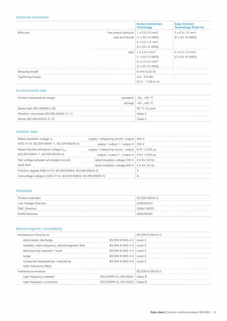
– Tool-free connection of rigid and flexible wires with wire end ferrule according to DIN 46228-1-A, DIN 46228-4-E Wire size: 2 x 0.5-1.5 mm², (2 x 20 - 16 AWG)

– Easy connection of flexible wires without wire end ferrule by opening the terminals

– No retightening necessary – One operation lever for opening both connection

terminals – For triggering the lever and disconnecting of wires

you can use the same tool (Screwdriver according to DIN ISO 2380-1 Form A 0.8 x 4 mm (0.0315 x 0.157 in), DIN ISO 8764-1 PZ1 ø 4.5 mm (0.177 in))

– Constant spring force on terminal point independent of the applied wire type, wire size or ambient conditions (e. g. vibrations or temperature changes)

– Opening for testing the electrical contacting – Gas-tight

Double-chamber cage connection terminals

– Terminal spaces for different wire sizes: fine-strand with/without wire end ferrule: 1 x 0.5-2.5 mm² (2 x 20 - 14 AWG), 2 x 0.5-1.5 mm² (2 x 20 - 16 AWG) rigid: 1 x 0.5-4 mm² (1 x 20 - 12 AWG), 2 x 0.5-2.5 mm² (2 x 20 - 14 AWG)

– One screw for opening and closing of both cages – Pozidrive screws for pan- or crosshead screwdrivers

according to DIN ISO 2380-1 Form A 0.8 x 4 mm (0.0315 x 0.157 in), DIN ISO 8764-1 PZ1 ø 4.5 mm (0.177 in)

Both the Easy Connect Technology with Push-in terminals and screw connection technology with double-chamber cage connection terminals have the same connection geometry as well as terminal position.

2CD

C 2

53 0

25 F

0011

2CD

C 2

53 0

26 F

0011

4 - Current monitoring relays CM-SRS.1 | Data sheet

Functions

Operating controls

2CD

C 2

51 0

55 V

0011

1 Adjustment of the hysteresis (MIN = Default)

2 Adjustment of the threshold value (MIN = Default)

3 Indication of operational states

U/T: green LED – control supply voltage

R: yellow LED – relay status

U: red LED – over- / undercurrent

4 DIP switches (see DIP switch functions)

Application

The current monitoring relays CM-SRS.1 are designed for use in single-phase AC and/or DC systems for over- or undercurrent monitoring. The devices are available with different supply voltage ranges and work according to the open-circuit principle.

Operating mode

The CM-SRS.1 with 1 c/o (SPDT) contact are available in 2 versions with 3 measuring ranges: 3-30 mA, 10 100 mA, 0.1-1 A (CM-SRS.11) and 0.3-1.5 A, 1-5 A, 3-15 A (CM-SRS.12). The measuring range is selected by connecting the monitored wire to the corresponding terminal B1/B2/B3-C.

The units are adjusted with front-face operating controls. The selection of over- b or undercurrent monitoring a is made with a DIP switch. Potentiometers, with direct reading scale, allow the adjustment of the threshold value I and of the hysteresis %. The hysteresis % is adjustable within a range of 3 to 30 % of the threshold value.

1

3

2

4

Data sheet | Current monitoring relays CM-SRS.1 - 5

Function diagrams

Overcurrent monitoring b

The current to be monitored (measured value) is applied to terminals B1/B2/B3-C. The control supply voltage applied to terminals A1-A2 is displayed by the glowing green LED.

If the measured value exceeds the adjusted threshold value, the output relay energizes and the red LED (overcurrent) and the yellow LED (relay energized) glow.

If the measured value drops below the threshold value minus the adjusted hysteresis, the output relay de-energizes and the red and yellow LEDs turn off.

A1-A2

11-14 (15-18) 11-12 (15-16)

Threshold

Hysteresis

Measured value

green LED

red LED

yellow LED

2CD

C 2

52 2

08 F

0205

Undercurrent monitoring a

The current to be monitored (measured value) is applied to terminals B1/B2/B3-C. The control supply voltage applied to terminals A1-A2 is displayed by the glowing green LED.

If the measured value drops below the adjusted threshold value, the output relay energizes, the red LED flashes W (undercurrent) and the yellow LED (relay energized) glows.

If the measured value exceeds the threshold value plus the adjusted hysteresis, the output relay de-energizes and the red and yellow LEDs turn off.

A1-A2

11-14 (15-18) 11-12 (15-16)

Threshold

Hysteresis

Measured value

green LED

red LED

yellow LED

2CD

C 2

52 2

09 F

0205

6 - Current monitoring relays CM-SRS.1 | Data sheet

Electrical connection

A1 A2

A1 1115

B1 B2 B3

A2

1115

1216 1418

1418 1216

C

B1 B2 B3

C

2CD

C 2

52 2

04 F

0005

A1-A2 Rated control supply voltage

B1-C Measuring range 1: CM-SRS.11: 3-30 mA

CM-SRS.12: 0.3-1.5 A

B2-C Measuring range 2: CM-SRS.11: 10-100 mA

CM-SRS.12: 1-5 A

B3-C Measuring range 3: CM-SRS.11: 0.1-1 A

CM-SRS.12: 3-15 A

1115-1216/1418 Output contact - open-circuit principle

Connection diagram

DIP switches

2CD

C 2

52 2

72 F

0005

1 ON Undercurrent monitoring

OFF Overcurrent monitoringOFF = Default

Data sheet | Current monitoring relays CM-SRS.1 - 7

Technical data

Data at Ta = 25 °C and rated values, unless otherwise indicated

Input circuits

Supply circuit A1-A2

Rated control supply voltage Us 110-130 V AC 220-240 V AC 24-240 V AC/DC

Rated control supply voltage Us tolerance -15...+10 %

Rated frequency 50/60 Hz 50/60 Hz or DC

Typical current / power consumption 24 V DC - - 30 mA / 0.75 W

115 V AC 24 mA / 2.6 VA - 17 mA / 1.9 VA

230 V AC - 12 mA / 2.6 VA 11 mA / 2.6 VA

Power failure buffering time 20 ms

Transient overvoltage protection varistors

Measuring circuit B1/B2/B3-C

Monitoring function over- or undercurrent monitoring configurable

Measuring method TRMS measuring principle

Measuring inputs CM-SRS.11 CM-SRS.12

terminal connection B1-C B2-C B3-C B1-C B2-C B3-C

measuring range 3-30 mA 10-100 mA 0.1-1 A 0.3-1.5 A 1-5 A 3-15 A

input resistance 3.3 Ω 1 Ω 0.1 Ω 0.05 Ω 0.01 Ω 0.0025 Ω

pulse overload capacity t < 1 s 500 mA 1 A 10 A 1 A 50 A 100 A

continuous capacity 50 mA 150 mA 1.5 A 2 A 7 A 17 A

Threshold value adjustable within the indicated measuring range

Tolerance of the adjusted threshold value 10 % of the range end value

Hysteresis related to the threshold value 3-30 % adjustable

Measuring signal frequency range DC / 15 Hz - 2 kHz

Rated measuring signal frequency range DC / 50-60 Hz

Maximum response time AC 80 ms

DC 120 ms

Accuracy within the rated control supply voltage tolerance ΔU ≤ 0.5 %

Accuracy within the temperature range ΔU ≤ 0.06 % / °C

Timing circuit

Time delay TV none

Repeat accuracy (constant parameters) ±0.07 % of full scale

Tolerance of the adjusted time delay -

Accuracy within the rated control supply voltage tolerance -

Accuracy within temperature range -

User interface

Indication of operational states

Control supply voltage U/T: green LED V: control supply voltage applied

Measured value U: red LED V: overcurrent

W: undercurrent

Relay status R: yellow LED V: output relay energized

8 - Current monitoring relays CM-SRS.1 | Data sheet

Output circuits

Kind of output 1115-1216/1418 relay, 1 c/o (SPDT) contact

Operating principle open-circuit principle (output relay energizes if the

measured value exceeds b / falls below a the

adjusted threshold value)

Contact material AgNi

Rated operational voltage Ue (VDE 0110, IEC/EN 60947-1) 250 V

Minimum switching voltage / Minimum switching current 24 V / 10 mA

Maximum switching voltage / Maximum switching current 250 V AC / 4 A AC

Rated operational current Ie

(IEC/EN 60947-5-1)

AC12 (resistive) at 230 V 4 A

AC15 (inductive) at 230 V 3 A

DC12 (resistive) at 24 V 4 A

DC13 (inductive) at 24 V 2 A

AC rating (UL 508) utilization category (Control Circuit Rating Code) B 300

max. rated operational voltage 300 V AC

max. continuous thermal current at B 300 5 A

max. making/breaking

apparent power at B 300

3600/360 VA

Mechanical lifetime 30 x 106 switching cycles

Electrical lifetime AC12, 230 V, 4 A 0.1 x 10⁶ switching cycles

Maximum fuse rating to achieve

short-circuit protection

n/c contact 6 A fast-acting

n/o contact 10 A fast-acting

General data

MTBF on request

Duty time 100 %

Dimensions (W x H x D) product dimensions 22,5 x 85,6 x 103,7 mm (0,89 x 3,37 x 4,08 in)

packaging dimensions 97 x 109 x 30 mm (3,82 x 4,29 x 1,18 in)

Weight Screw connection

technology

Easy Connect

Technology (Push-in)

net weight CM-SRS.11 Version 24-240 V AC/DC 0.145 kg (0.320 lb) 0.137 kg (0.302 lb)

Version 110-130 V AC 0.161 kg (0.355 lb) 0.153 kg (0.337 lb)

Version 220-240 V AC 0.161 kg (0.355 lb) 0.153 kg (0.337 lb)

CM-SRS.12 Version 24-240 V AC/DC 0.137 kg (0.302 lb) -

Version 110-130 V AC 0.168 kg (0.370 lb) -

Version 220-240 V AC 0.168 kg (0.370 lb) -

gross weight CM-SRS.11 Version 24-240 V AC/DC 0.147 kg (0.324 lb) 0.159 kg (0.351 lb)

Version 110-130 V AC 0.183 kg (0.403 lb) 0.175 kg (0.386 lb)

Version 220-240 V AC 0.183 kg (0.403 lb) 0.175 kg (0.386 lb)

CM-SRS.12 Version 24-240 V AC/DC 0.159 kg (0.351 lb) -

Version 110-130 V AC 0.200 kg (0.441 lb) -

Version 220-240 V AC 0.200 kg (0.441 lb) -

Mounting DIN rail (IEC/EN 60715),

snap-on mounting without any tool

Mounting position any

Minimum distance to other units 10 mm (0.39 in) at measured current > 10 A

Material of housing UL 94 V-0

Degree of protection housing IP50

terminals IP20

Data sheet | Current monitoring relays CM-SRS.1 - 9

Electrical connection

Screw connection technology

Easy Connect Technology (Push-in)

Wire size fine-strand with(out)

wire end ferrule

1 x 0.5-2.5 mm²

(1 x 20-14 AWG)

2 x 0.5-1.5 mm²

(2 x 20-16 AWG)

2 x 0.5-1.5 mm²

(2 x 20-16 AWG)

rigid 1 x 0.5-4 mm²

(1 x 20-12 AWG)

2 x 0.5-2.5 mm²

(2 x 20-14 AWG)

2 x 0.5-1.5 mm²

(2 x 20-16 AWG)

Stripping length 8 mm (0.32 in)

Tightening torque 0.6 - 0.8 Nm

(5.31 - 7.08 lb.in)

-

Environmental data

Ambient temperature ranges operation -20...+60 °C

storage -40...+85 °C

Damp heat (IEC 60068-2-30) 55 °C, 6 cycle

Vibration, sinusoidal (IEC/EN 60255-21-1) Class 2

Shock (IEC/EN 60255-21-2) Class 2

Isolation data

Rated insulation voltage Ui

(VDE 0110, IEC/EN 60947-1, IEC/EN 60255-5)

supply / measuring circuit / output 600 V

supply / output 1 / output 2 250 V

Rated impulse withstand voltage Uimp

(IEC/EN 60947-1, IEC/EN 60255-5)

supply / measuring circuit / output 6 kV 1.2/50 μs

supply / output 1 / output 2 4 kV 1.2/50 μs

Test voltage between all isolated circuits

(type test)

rated insulation voltage 250 V 2.0 kV, 50 Hz

rated insulation voltage 600 V 2.5 kV, 50 Hz

Pollution degree (VDE 0110, IEC/EN 60664, IEC/EN 60255-5) 3

Overvoltage category (VDE 0110, IEC/EN 60664, IEC/EN 60255-5) III

Standards

Product standard IEC/EN 60255-6

Low Voltage Directive 2006/95/EC

EMC Directive 2004/108/EC

RoHS Directive 2002/95/EC

Electromagnetic compatibility

Interference immunity to IEC/EN 61000-6-2

electrostatic discharge IEC/EN 61000-4-2 Level 3

radiated, radio-frequency, electromagnetic field IEC/EN 61000-4-3 Level 3

electrical fast transient / burst IEC/EN 61000-4-4 Level 3

surge IEC/EN 61000-4-5 Level 3

conducted disturbances, induced by

radio-frequency fields

IEC/EN 61000-4-6 Level 3

Interference emission IEC/EN 61000-6-3

high-frequency radiated IEC/CISPR 22, EN 55022 Class B

high-frequency conducted IEC/CISPR 22, EN 55022 Class B

10 - Current monitoring relays CM-SRS.1 | Data sheet

Technical diagrams

Load limit curves

300

200

1008060504030

20

101 2 4 6 10

I A

V

V

0.1 0.2 0.5

resistive load

2CD

C 2

52 1

94 F

0205

AC load (resistive)

300

200

100 80 60 50 40 30

20

10 1 2 4 6 10

I A

V

V

0.1 0.2 0.5

resistive load

2CD

C 2

52 1

93 F

0205

DC load (resistive)

cos ϕ

F

0.5

0.1 0.2 0.3 0.4 0.5 0.6 0.7 0.8 0.9 1.0

0.6

0.7

0.8

0.9

1.0

2CD

C 2

52 1

92 F

0205

Derating factor F for inductive AC load

Switching current [A]

Sw

itchi

ng c

ycle

s

250 Vresistive load

2CD

C 2

52 1

48 F

0206

Contact lifetime

Data sheet | Current monitoring relays CM-SRS.1 - 11

Dimensions

in mm and inches

113.4 4.47”

22.5 0.89”

85.6

3.37

103.7 4.08”

105.9 4.17”

2CD

C 2

52 0

09 F

0011

Accessories

in mm and inches

22.5 0.89”

68 2.68

110.5 4.31”

8 0.32”

4.8 0.19”

front to back

2CD

C 2

52 0

10 F

0011

6.5 62.5

60

1011

.5

20

0.25

6”

2.461”

2.362”

70 2.756”

0.39

4”

0.78

7”

0.45

3”

2CD

C 2

52 0

08 F

0010

19.94T22 7.

850.30

9”

0.783”

22.20.874”

2CD

C 2

52 0

20 F

0011

ADP.01 ‑ Adapter for screw mounting MAR.12 ‑ Marker label for devices with DIP switches

COV.11 ‑ Sealable transparent cover

Further documentation

Document title Document type Document number

Electronic products and relays Technical catalogue 2CDC 110 004 C020x

CM-SRS.1, CM-SRS.2 Instruction manual 1SVC 730 610 M0000

You can find the documentation on the internet at www.abb.com/lowvoltage -> Control Products -> Electronic Relays and Controls -> Single Phase Monitors

ABB STOTZ‑KONTAKT GmbHP. O. Box 10 16 8069006 Heidelberg, GermanyPhone: +49 (0) 6221 7 01-0Fax: +49 (0) 6221 7 01-13 25E-mail: [email protected]

You can find the address of your local sales organisation on the ABB home pagehttp://www.abb.com/contacts -> Low Voltage Products and Systems

Contact us

Note:We reserve the right to make technical changes or modify the contents of this document without prior notice. With regard to purchase orders, the agreed particulars shall prevail. ABB AG does not accept any responsibility whatsoever for potential errors or possible lack of information in this document.

We reserve all rights in this document and in the subject matter and illustrations contained therein. Any reproduction, disclosure to third parties or utilization of its contents – in whole or in parts – is forbidden without prior written consent of ABB AG.

Copyright© 2011 ABB All rights reserved

Do

cum

ent

num

ber

2C

DC

112

167

D02

01 (1

1.20

11)


Recommended