Page 1
Current Research and Development ofWireless Power Transfer via Radio Waves
and the Application [DML]
Oct. 19, 2016
Naoki Shinohara, Professor,
Research Institute for Sustainable Humanosphere, Kyoto University
[email protected]
Page 2
Kyoto and Kyoto University
2
KyotoWinter
Autumn
Spring APMC2018 will be held at Kyoto.
- Kyoto Univ. Data (2015) -
Professors : 1,032 (5,445 Employees)
Students : 13,569 (Under Graduate)
4,773 (Master), 3,671 (Ph.D)
Novel Prizes (Prof. Yamanaka, Prof. Yukawa,
Prof. Tomonaga, Prof. Tonegawa, Prof. Fukui..)
Main Campus
Uji Campus
Kyoto Univ.
Kyoto Univ.
Tokyo
Page 3
RISH, Kyoto Univ.
Microwave Power Transmission Field Experiment in Kyoto Univ.
1993
Second MPT Rocket
Experiment
- ISY-METS -
1994-95
Ground-to-Ground
MPT Experiment
1996
Retrodirective
MPT System
Open Experiment
1983
First MPT Rocket Experiment
In the World - MINIX-1992
MPT Experiment to
Fuel-free Airplane
- MILAX -
2001
Solar Power
Radio Integrated
Transmitter
- SPRITZ -
2009
Airship-to-Ground
MPT Experiment
3
Page 4
4
Aug., 1992, by Kyoto Univ., Kobe Univ., CRL, etc
Page 5
5
Jan., 1993, by Kyoto Univ., Kobe Univ., ISAS, Texas A&M Univ., etc
Page 6
6
Power from Airship (50m above, 2.45GHz, phased array with two magnetrons)
March, 2009, at Uji, Kyoto, Japan
Page 7
Contents1. Overview of Wireless Power Transfer via Radio Waves2. Current R&D of WPT via Radio Waves3. Key Technology : Rectenna - Rectifying Antenna4. Introduction of IEEE, IEICE, ITU5. Conclusion
7
SHARP Airplane exp.1987@Canada
MPT to helicopterBy W. Brown 1964, 1968
MPT rocket exp.1983 by Kyoto Univ., ISAS
Island-Island MPT (150km)in Hawaii2008 by Kobe Univ., NASA
Page 8
8
Overview of Wireless Power Transfer
via Radio Waves
Page 9
WPT Theory
Faraday’s law :
NS
Load
High
Frequency
Ampere’s law : H
IδH
NS
Coil
Electromagnetic Wave
(Radio Wave)Electric Field Electric Field
Magnetic FieldMagnetic Field
High
Frequency
Transmitting
AntennaReceiving
Antenna
Raidowave Power (Electric Power)Maxwell’s Equations
Inductive Coupling WPT
WPT via Radio Waves
H
0
Bdiv
Ddiv
t
BErot
t
DJHrot
9
)/( 2mW
HES
Radio wave itself is energy.
What we need is frequency conversion only.
Electromagnet
Page 10
Various Wireless Power Transfer
I
I
H
Supply
User
I
I
H
Supply
User
L
L
C
C
Resonance of L and C
Transmitter
Transmitted
Power
Receiver
→Power Only Carrier for WPT
Very Narrow
Electric Power
To User
Frequency
Time and
Space
Inductive
Coupling
(Magnetic)
Resonance
Coupling
Conductive
Coupling
10
E
V
V
Radio Waves
(Microwaves)
Page 11
History of Wireless Power Transfer
19th
Cen-
tury
20th
Cen
-tury
21st
Cen
-Tury
Maxwell’s Eq.
X
Failure
•Lower Power Density
than User Requirement
in 19th Century
Digital Tech. =
Lower Power Device
Wireless
Communication
Tesla’s Dream
150kHz, 300kW
Microwave Power
Transmission by W.C. Brown
Success
• High power
density via
microwave
But..
• But Antenna was
still larger than
user requirement
2.45GHz,
1-450kW
2.45GHz, 1GW
Solar Power
Satellite (SPS)
Microwave Tubes
WPT and Energy
Harvesting
900MHz, 2.45GHz,
5.8GHz, <1W
Resonance WPT and Inductive WPT
Japanese
Contribution
5.8GHz, <1kW
<10MHz,
5W-100kW
Wireless Charger
of EV via Inductive
R&D Project of
Wireless Charger via
Inductive Coupling
Hutin,
Le-Blanc
PATH(US)
Tulip(France)
IPT(German)
BPF
Microwave
Heating
Microwave
Chemistry
Iron-Making,
etc. > kW
Inductive
Heating
Microwave Oven
2.45GHz, <kW
Poyinting
Vector
Radar
AirFuel
AllianceWiPoT
Standardization
WPC
[Qi]WIPE
1960s
1940s
1980s
1980s
2000s2010s
1900s
1900s
IC Card,
Shaver Charger
11
Page 12
12
Current R&D of WPT via Radio Waves
Page 13
Various Wireless Power Transfer via Radio Waves(a) Beam-type
(High efficiency with higher frequency)
(b)Ubiquitous-type (Low efficiency, like RF-ID)
(c) Energy Harvesting
(No power source)
Transmitter
Receiver
→Power
Time and Space
Information
Frequency
Wide
Electric Power
to User Receiver
→Power
Transmitted
Power
Transmitted
Power
Transmitted
Power
Transmitter
Transmitted
Power (Broad)
→ Electric
PowerOnly Carrier for WPT
Very Narrow
Frequency
Time and
Space
→ Electric
Power→ Electric
Power
13
(d) In Closed Area (like Waveguide)
Transmitter
Transmitted Power
Receiver→
Power
Page 14
Energy Harvesting from TV Tower Signal by Univ. of Tokyo and Georgia Inst. of Tech.
14
Page 15
T. Furuta, et al., “The 500MHz band low power rectennafor DTV in the Tokyo area”, Proc. of WPTc2016
15
Frequency plan at Tokyo area
Center
frequencyERP
TV
Stations
491MHz 11.5 kW MX
521MHz 69 kW CX
527MHz 69 kW TBS
533MHz 69 kW TX
539MHz 69 kW EX
545MHz 69 kW NTV
551MHz 68 kW NHK(Edu.)
557MHz 68 kW NHK
10km
15km
20km
Tokyo
metropolitan
area
TOKYO
SKYTREE
Measurement
points
25 km
Distance (km)2 4 6 8 10 20
0
0.5
1
-40
-30
-20
-10
-50
Outp
ut
dc v
oltage (
V)
Inp
ut
pow
er
(dB
m)
Input power
Output voltage
L type LPF
Cockcroft-Walton
type rectifier(m=2)
Diode
HSMS-285C
Load resistance terminals
1.6kWAntenna
Page 16
Weak point of ubiquitous network
society is a power source.
We propose a wireless power source with
microwave power transmission (MPT). In
most advanced system, we bring only a
receiving system, rectenna instead of heavy
battery. At first step, we try to charge a
battery via microwave power.
Receiving
System
Transmitting System
Ubiquitous Power Source (UPS)
Wireless Power source
in every time
and in everywhere“Ubiquitous Power Source”
Wireless
Charge
Shinohara, N., et al., “Study on Ubiquitous Power Source with Microwave Power Transmission”, Proc. of
International Union of Radio Science (URSI) General Assembly 2005, C07.5(01145).pdf, 2005 16
Page 17
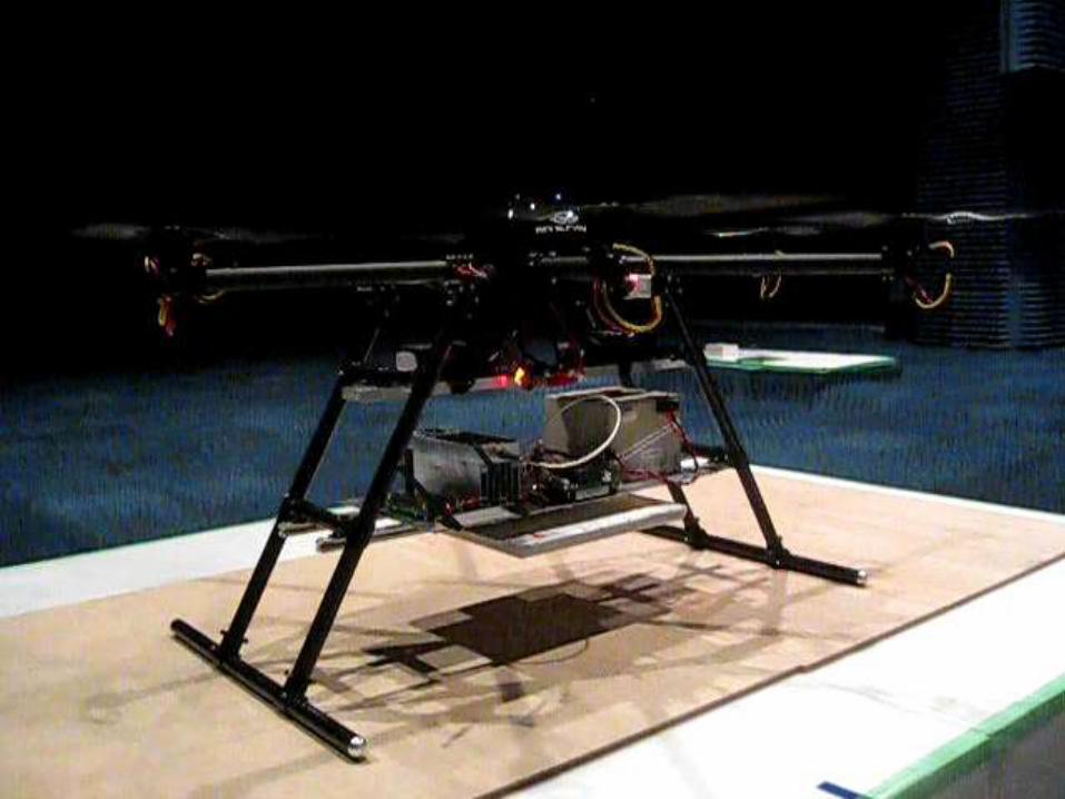
Demonstration of WPT-powered Sensors with Drone
17
自律プログラム飛行高度30m~50m
高度 約6m~8m
遭難者発見データ飛行経路情報マルチコプタ-動作情報WBLS動作情報
遭難者救援支援マルチコプタ基地
電波障害物
遭難者(救命カード保有)
中継器(必要に応じて)
電子基準点
遭難者救助対策本部
最大探査距離(TBD)km
マイクロ波電力
遭難者IDデータ
次期マルチコプター
by WiPoT, Kyoto Univ., Mini-Surveyor Consortium, Autonomous Control Systems Laboratory Ltd.
Demo (Jul. 16, 2015)
Applications : Rescue of victims, WPT-powered sensors at volcano,
Inspection of infrastructures (Bridges, Tunnels..)
Victim(with Rectenna-
Vital Sensor Card)Drone Station
for Rescue
Obstacle of Radio
ID Data of
Victim
Height 6-8m
Microwave powerVictim Data
Flight Path Data
Drone Health Data
WBLS Health Data
Transponder(If necessary)
Autonomous Programmed Flight
Height 30-50m
Next Term Drone
Electric Reference Point
Rescue HeadquarterFlying Drone
WPT-Powered
Sensor
4mMicrowave
(5.8GHz, -8.74W)
Maximum Search Distance (TBD) km
5.8GHz, 8.74W from 8x8 array (21dBi)
6.1mW Received at 2 rectennas (10.2dBi)
Page 19
Commercial Products of WPT via Radio Waves
• Venture Companies of Wireless Charger of Smart Phone* ‘Cota’ by Ossia inc. (WiFi-Band) http://www.ossiainc.com/
* ‘Wattup’ by Energous corp. (2.45GHz and 5.8GHz Band)
http://www.energous.com/
• Japanese Company (Dengyo)of Battery-less Sensor
(900MHz-Band) http://www.den-gyo.com/solution/solution10_b.html
UHF Band Transmitter
(920 MHz Band)
Re
ctifyin
gC
ircuit
Tran
s-M
itter
Sensor &Micro Computer
A few m
Wireless Power
DataTransmission315 MHz Band
Wireless Sensor
19
KDDI (Big 3 Carrier
in Japan) supports
Ossia
Based on FCC-15
Page 20
20
Surface WPT (2D WPT) by NICT and Univ. of Tokyo
Noda, A., and H. Shinoda, “Selective wireless power transmission through high-Q flat waveguide-ring
resonator on 2-D waveguide sheet,” IEEE Trans. MTT, Vol. 59, No. 8, pp. 2158–2167, 2011.
ARIB Standard STD-T113
(Dec. 2015)
Frequency : 2.498GHz±1MHz
Power : < 30W
ARIB : Association of Radio Industries
and Businesses
Page 21
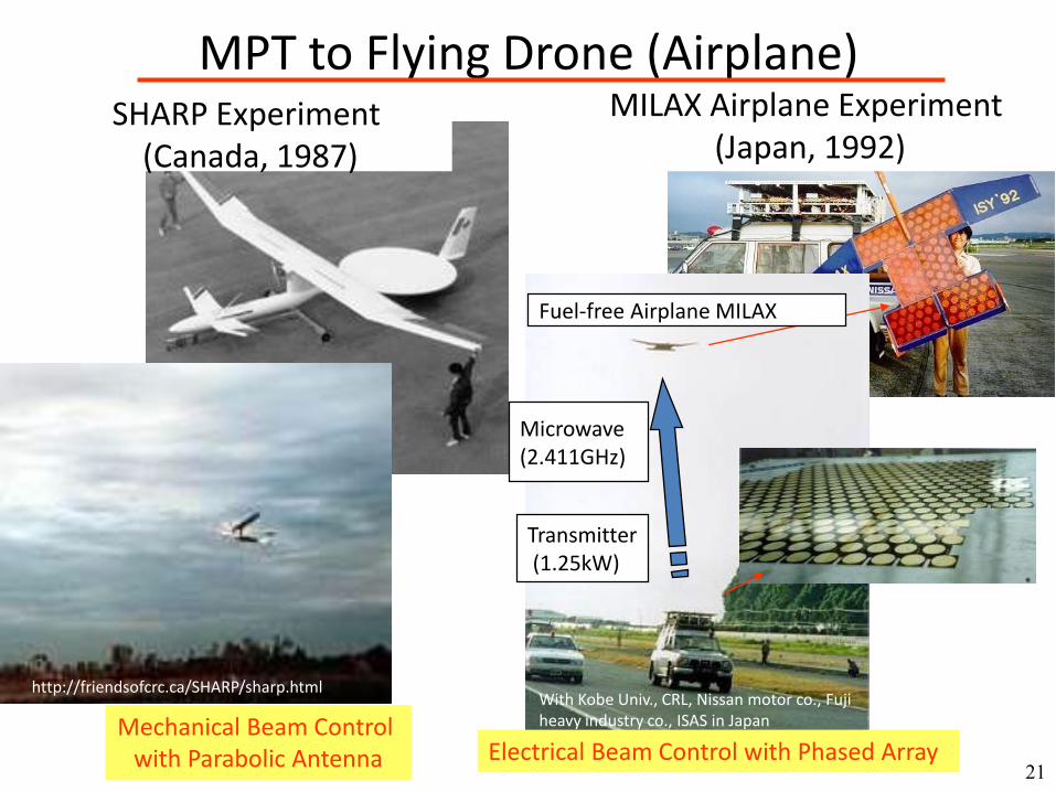
21
MILAX Airplane Experiment(Japan, 1992)
With Kobe Univ., CRL, Nissan motor co., Fuji heavy industry co., ISAS in Japan
Transmitter(1.25kW)
Microwave(2.411GHz)
http://friendsofcrc.ca/SHARP/sharp.html
Electrical Beam Control with Phased Array Mechanical Beam Control
with Parabolic Antenna
Fuel-free Airplane MILAX
SHARP Experiment(Canada, 1987)
MPT to Flying Drone (Airplane)
Page 22
A new microwave power supply system
• In Driving• In Parking
Transmission Distance1-4m Transmission Distance 4-10m
Transmitting Antenna
Transmitting
Antenna
Rectennas
Rectennas
Dis-
Tance
3m
Lights &
Transmitter Stand
Microwave
Beam
22Collaborative Research with Volvo
22
Page 23
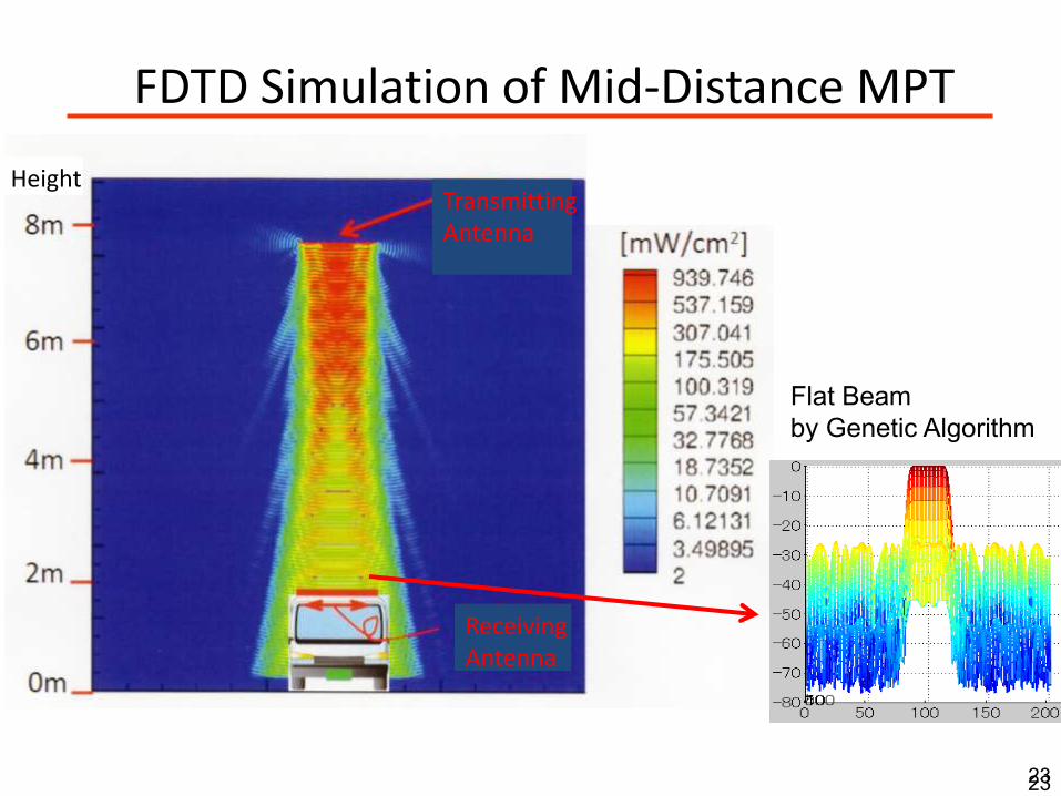
TransmittingAntenna
ReceivingAntenna
Height
FDTD Simulation of Mid-Distance MPT
23
Flat Beam
by Genetic Algorithm
23
Page 24
Power Density~350W/ /㎡at rectenna center
~10W/ /㎡at rectenna edge
WPT Ground Test
Microwave
Beam
MPT Experiment on Feb. 2015Thin-High Efficiency Phased Array with GaN MMIC
55m
2.5cm thickness phased array
GaN MMIC Amplifiers
5.8GHz, 1.8kW
Developed by Mistubishi Electric Corp. (Phased Array), IHI Aerospace (Rectenna Array), Supported by METI 24
Page 25
Microwave
Beam
MPT Experiment on Feb. 2015 (2)High Power-Low Cost Phased Array with Magnetrons
500m
Magnetron phased array
2.45GHz, 10kW
Height 13m
Developed by Mistubishi Heavy Industries, Supported by METI 25
Page 26
26
Future Dream of MPT:
Solar Power Satellite (SPS)
1GW Solar Power Station
2kmf Solar Cells
2kmf Microwave Antenna
< 10,000 ton weight
36,000km
Wireless Power
Transmission
via Microwave
2kmf
Receiving Antenna
Energy Availability Factor
Ground PV
: < 15% (Night, Rain…)
Space PV (SPS)
: >90% (No Night in 36,000km Orbit,
No Rain by Microwave Propagation)
-> SPS is huge, stable, and CO2-less
Power Station
Page 27
27
Key Technology : Rectenna
- Rectifying Antenna -
Page 28
28
Rectenna – Rectifying Antenna –Radio Wave -> DC Power Converter
Brown&JPL Rectenna
(2.45GHz) 1970-75
Rectenna by Hokkaido Univ.
(2.45GHz) 1984
Rectenna byTexas A&M Univ.
(35GHz) 1992
Rectenna
byDENSO co.
(21GHz) 1997Commercial Rectenna by DENGYO co. (2.45GHz) 2011
Rectenna
by Kyoto Univ.
(5.8GHz) 2001
Rectenna by Intel co.
(674 - 680 MHz) 2009
antenna
diode
antenna
diodeantenna
diode(backside)
antenna
diode
An-tenna
LPF
OutputFilterwith
Capa-citance
Radio Wave
DCTo Load
Page 29
29
Rectifier1. Half Wave (Theoretically 50%)2. Full Wave (Theoretically 100%)3. Bridge (Theoretically 100%)4. Single Shunt (Theoretically 100%)5. Double Voltage6. Charge Pump etc.
“Theoretically 100%”
is most important
for WPT and harvesting.
C
λ /4 line
Diode
LPF
Page 30
Theory of Rectifier by Ohira
30T. Ohira, “Power efficiency and optimum load formulas on RF rectifiers featuring flow-angle equationss”,IEICE Electronics Express (ELEX), Vol.10, No.11, 2013, pp.1- 9
Page 31
Input LPF Output Filter
Z =ZL + jZ0tan(β λ /4)
Z0 + jZLtan(β λ /4)Z0=
ZLCL→∞ 0 (even harmonic wave)
Z02
ZL
CL→∞ ∞ (odd harmonic wave)Z =
ZL + jZ0tan(β λ /4)
Z0 + jZLtan(β λ /4)Z0=Z =
ZL + jZ0tan(β λ /4)
Z0 + jZLtan(β λ /4)
ZL + jZ0tan(β λ /4)
Z0 + jZLtan(β λ /4)Z0=
ZLCL→∞ 0 (even harmonic wave)ZLCL→∞ 0 (even harmonic wave)
Z02
ZL
CL→∞ ∞ (odd harmonic wave)Z0
2
ZL
Z02
ZL
CL→∞ ∞ (odd harmonic wave)
Theory of Single Shunt Rectifier
cycle as a result of
Fourier transform
Full wave
with one diode
(theoretically 100%)
ZL=
1+ jωC LR
L
RL
Open for odd harmonics
Short for even harmonics
R. J. Gutmann et al., “Power Combining in an Array of Microwave Power Rectifiers”,
IEEE Trans. Microwave Theory Tech., Vol.MTT-27, No.12, pp.958-968, 1979. 31
IL (DC)
I1 (Microwave)
I2 Diode
off on off on
IR at Diode (Doubler)
Like Class-F Amplifier
Page 32
Theory by T.Yoo-K.Chang
RF/DC conversion efficiency
Power loss on diodediodeonRoffRonloss LOSSLOSSLOSSP
ss ,,,
dR
VVVLOSS
on
ons
bibidiodeon
)(
2
1,
on
on
on
o
bi
s
L
dc
Ron
V
V
R
R
P
LOSSA s
tan
2
3
cos2
111
2
2
,
on
on
on
o
bijLs
dc
Roff
V
VCRR
P
LOSSB s
tan
cos1
2 2
22
,
onon
o
bi
o
bi
s
L
dc
diodeon
V
V
V
V
R
R
P
LOSSC
tan1
,
CBAPP
P
lossdc
dcd
1
1
on
on
sd
R
VVLOSS
s
biRon
2
,2
1
dR
VVLOSS
on
onS
dRsoff
2 2
,
2
1
Power loss on Rs
at diode ON
T.- W. Yoo and K. Chang, “Theoretical and Experimental Development of 10 and 35 GHz Rectennas”, IEEE Trans. MTT, Vol.40, No.6, 1992, pp.1259- 1266 32
Power loss on Rs
at diode OFF
Power loss on Rj
at diode ON
Page 33
Rs, Cjo and Efficiency by T.Yoo-K.Chang
r=Rs/RLPoint A : Rs = 0.5Ω, CjO= 3 pf
for a 2.45 GHz, RL=100Ω
Point B : Rs = 4.85Ω, CjO= 0.13 pf
for 35 GHz, RL=100Ω
33T.- W. Yoo and K. Chang, “Theoretical and Experimental Development of 10 and 35 GHz Rectennas”, IEEE Trans. MTT, Vol.40, No.6, 1992, pp.1259- 1266
Page 34
Frequency Characteristics of Efficiency of Rectenna
34
2.45GHz 5.8GHz 14GHz 24GHz 35GHz
100%
50%
0%
10GHz
60%
70%
80%
90%
40%
30%
20%
10%
100GHz45GHz 62GHz 72GHz
Frequency
RF-
DC
Co
nve
rsio
n E
ffic
ien
cy
: Diode : CMOS
antenna
diode
by Brown&JPL
(2.45GHz) 1970-75
by Texas A&M Univ.
(35GHz) 1992
Products by DENGYO co. (2.45GHz) 2011
by DENSO co.
(14GHz) 2000
MMIC by Kyoto Univ.
(24GHz) 2012
by École Polytechnique
Montréal (94GHz) 2015
antenna
diode
by Tel-Aviv University
(75-110GHz) 2014
532um x 910um
Page 35
Input Poweror Connected Load
T.- W. Yoo and K. Chang, “Theoretical and Experimental Development of 10 and 35 GHz Rectennas”, IEEE Trans. MTT, Vol.40, No.6, 1992, pp.1259- 1266
Higher Order
Harmonics Effect
Typical Characteristics of RF-DC Conversion Efficiency with Input Power
35
RF-DC conversion
efficiency
100%
V
I
VJ
(0.2-0.3V)
Vbr
(10-30V)
-VJ
Rdiode
“rectenna”region“detector”
region
VJ Effect
Vbr EffectDiode Maximum
Efficiency Curve
To increase the peak RF-DC conversion efficiency1) Low RC diode2) High voltage at diode (almost breakdown)3) Higher harmonics combination (like class-F amplifier)
Page 36
Rectenna Developed by W. C. Brown (1970-75)
Antenna - Dipole
LPF – LC LPF
Rectifier – Single Shunt
Diode - ? (GaAs-schot.)
Frequency - 2.388 GHz
RF-DC Eff. (all) - 82±2%
* for Goldstone Exp.
- W. C. Brown, The History of Power Transmission by Radio
Waves, IEEE Trans. MTT, Vol. 32, No. 9, pp.1230-1242,
1984
- W. C. Brown, The History of the Development of the Rectenna,
Proc. Of SPS microwave systems workshop, pp.271-280, Jan.
15-18, 1980, at JSC-NASA
- R. M. Dickinson, Microwave Power System for Space power,
Raumfahrtforschung, Vol. 20, No.5, pp.238-241, 1976
36
Page 37
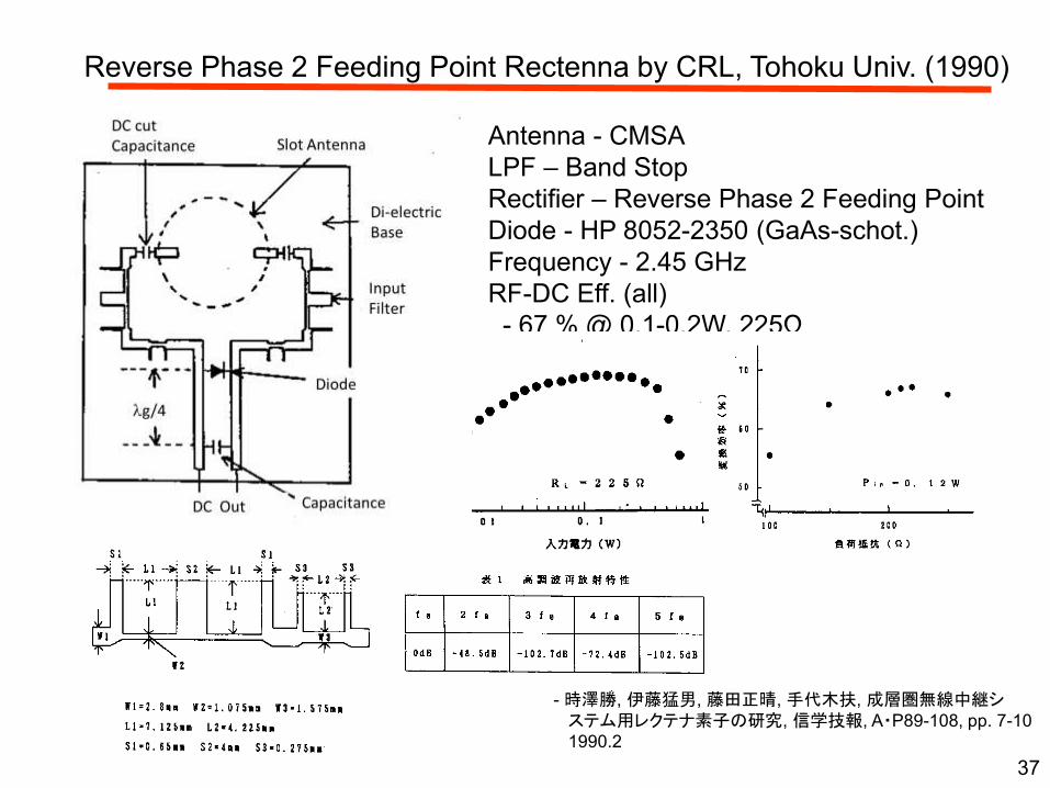
Reverse Phase 2 Feeding Point Rectenna by CRL, Tohoku Univ. (1990)
Antenna - CMSA
LPF – Band Stop
Rectifier – Reverse Phase 2 Feeding Point
Diode - HP 8052-2350 (GaAs-schot.)
Frequency - 2.45 GHz
RF-DC Eff. (all)
- 67 % @ 0.1-0.2W, 225Ω
- 時澤勝, 伊藤猛男, 藤田正晴, 手代木扶, 成層圏無線中継システム用レクテナ素子の研究, 信学技報, A・P89-108, pp. 7-10
1990.2
37
Page 38
Rectifier with Rat-Race in Japan (1993)
Antenna - no
LPF - no
Rectifier – Rat-Race (Hybrid Reverse
Phase Conbination)
Diode - 1SS97 (Si-schot.) and
HP5082-2350 (GaAs-schot.)
Frequency - 2.45 GHz
RF-DC Eff. (Rectifier)
- 70 % @ 500mW
- 小林祐司, 関一, 伊藤猷顯, 成層圏無線中継システム用レクテナ整流回路, 1992年信学会秋季大会予稿集(通信), p.2-102,
1992
- 小林祐司, 関一, 伊藤猷顯, 成層圏無線中継システム用レクテナ整流回路の特性改善, 1993年信学会春季大会予稿集(通信), p.2-37, 1993
38
Page 39
AC-WPT (Spain)
39José R. Perez-Cisneros, et al. (CTTC), “Class-E Power Converters for AC (50/60 Hz) Wireless Transmission”. Proc. of IMS2016
Page 40
PA-Rectifier Duality by Univ. of Colorado
• “time-reversal” duality (current negative)• Any amplifier will function as rectifier, and
at microwave frequencies as a self-synchronous rectifier (no gate drive).
40
Page 41
Measured Performance
41
Amplifier, 2.11GHz, Class F-1
PAE=83%
Pout=8W at Vdd=28V
Rectifier, self-synchronized
2.11GHz, Class F-1
85% conversion efficiency
Vout = 35V, Pin=10W
Vout = 26V, Pin=8W
“High-Efficiency Harmonically Terminated
Diode and Transistor Rectifiers,” M.
Roberg, T. Reveyrand, I. Ramos, E.A.
Falkenstein, Z. Popović, IEEE Trans.
Microwave Theory Tecnh., Vol. 60, No.12,
pp.4043-4052, Dec. 2012
Page 42
Class-D Rectenna by Univ. of British Colombia (2015)
S. Dehghani, T. E. Johnson, ”A 2.4 GHz CMOS Class D Synchronous Rectifier”,
Proc. of IMS2015 42
Page 43
Class-E Rectenna by Univ. of Cantabra (2015)
43An E-pHEMT Self-biased and Self-synchronous Class E Rectifier
M. N. Ruiz and J. A. García, University of Cantabria, Spain, 2015
Page 44
Class-F Rectenna by Kyoto Univ. (2011)
44Ken Hatano, et al., “Development of Class-F Load Rectennas”,Proc. of 2011 IEEE IMWS-IWPT2011,2011.5, pp.251-254
Ken Hatano et. Al, “Development of MMIC Rectenna at 24GHz”, Proc. of RWW2011
Page 45
Input Poweror Connected Load
T.- W. Yoo and K. Chang, “Theoretical and Experimental Development of 10 and 35 GHz Rectennas”, IEEE Trans. MTT, Vol.40, No.6, 1992, pp.1259- 1266
Higher Order
Harmonics Effect
How do we increase the RF-DC conversion efficiency for energy harvesting?
45
RF-DC conversion
efficiency
100%
V
I
VJ
(0.2-0.3V)
Vbr
(10-30V)
-VJ
Rdiode
“Harvesting”region
VJ Effect
Vbr EffectDiode Maximum
Efficiency Curve
Harvested Power ( <mW)
To increase the RF-DC conversion efficiency at Low Power
2) High voltage at diode (almost breakdown)
Page 46
Suitable Rectenna for Energy Harvesting (1/2)• Charge Pump -> High Voltage but Low Efficiency
• Impedance Matching (Kyoto Univ. etc., Japan)
- 50% @ 1mW, 5.8GHz (2004)
• Active Impedance Matching (MIT, USA, 2015)
• Rectifying Circuit with Resonator
(Tohoku Univ. (2006), Toyama Univ. (2013), Japan)
- 40% @ 100mW, 900MHz
• High Impedance Circuit and Antenna (Kanazawa Inst. Tech. (2016), Japan)
46
Page 47
Self-powered DCM Buck-boost Converter
47
Driving voltage of control circuit ( 𝑉out > 𝑉in)𝑉in ⇔ I-type (High-power); 𝑉out ⇔O-type (Low-power)
𝑅in =2𝐿𝑓h
𝐷h2
If: 𝐿 = 220 µH 𝑓h = 20 kHz 𝐷h= 0.5 Then: 𝑅in = 35 Ω
Input resistance 𝑅in:independent of input voltage and load
resistance; decided by inductance, frequency and duty-on rate.
Operating waveform
Expansion
Yong Huang, Naoki Shinohara, and Tomohiko Mitani, “A Constant Efficiency of Rectifying Circuit
in an Extremely Wide Load Range”, IEEE-Trans. MTT, Vol. 62, No.4, pp.986-993, 2014
Page 48
Experiment on Self-powered RF-DC-DC Circuit
48
Buck-boost converter: 𝑅in-𝑅L RF-DC rectifier + Buck-boost converter experimental
results : Comparison of efficiency-load
System efficiency with converter
Rectifier without
converter
Rectifier with converter
Buck-boost converter
Yong Huang, Naoki Shinohara, and Tomohiko Mitani, “A Constant Efficiency of Rectifying Circuit
in an Extremely Wide Load Range”, IEEE-Trans. MTT, Vol. 62, No.4, pp.986-993, 2014
Page 49
Suitable Rectenna for Energy Harvesting (2/2)
49An E-pHEMT Self-biased and Self-synchronous Class E Rectifier
M. N. Ruiz and J. A. García, University of Cantabria, Spain
• Zero Bias Diode -> Low Efficiency (Bad diode parameter?)
• Self-biased and Self-synchronous Rectifier (Univ. of Cantabria)
Page 50
Input Poweror Connected Load
T.- W. Yoo and K. Chang, “Theoretical and Experimental Development of 10 and 35 GHz Rectennas”, IEEE Trans. MTT, Vol.40, No.6, 1992, pp.1259- 1266
Higher Order
Harmonics Effect
How do we increase the RF-DC conversion efficiency high power application?
50
RF-DC conversion
efficiency
100%
V
I
VJ
(0.2-0.3V)
Vbr
(10-30V)
-VJ
Rdiode
“High Power”region
VJ Effect
Vbr EffectDiode Maximum
Efficiency Curve
To increase the RF-DC conversion efficiency at High Power
2) High voltage at diode (almost breakdown) -> High breakdown voltage
Page 51
51
Power Divided Rectenna
A B
C
D
G
F 1
E 1 E 2
F 2
D: Diode
A: Input terminal
B: Output terminal
C: Chip capacitor
G: Ground
G
D
D
D
E ,E : lg/4 line21
F ,F : Capacitor1 2
A
C
BD
D
D
D
G
BD
D
D
D
G
G
C
A: Input terminal
B: Output terminal
C: Capacitor
D: Diode
G: Ground
A
GG C
B
C G G GC C
D D D D D D D D D D D D D D D D
B B B
D
G C GG GGC C C
D D D D D D D D D D D D D D D
BB B B
P5
A
B
D
G C
A
GG GGC C C
D D D D D D D D D D D D D D D
B B B
P1
(a) Top layer of 5 layer structure
(b) Bottom layer of 5 layer structure
RF Power
Common Ground
FrontBack
Rectifier
Single Rectifier
2-Divided Rectifer
4-Divided Rectifer
8-Divided Rectifier
RF
Input
DC
Output
Via-Hole
Via-Hole
松本 紘, 篠原 真毅,
“レクテナとレクテナ大電力化方法 ”,
特許番号3385472号, 2003.1.10
Page 52
52
64 PD-Rectenna with 256 Si Schottky barrier diodes
S11= -17.5 dB
S21= ・・S91
=-9.31 dB
Simulation
Experiment
8-way T-Junction Power Divider
•RF-DC Conversion Efficiency
52% @ 95W, 2.45GHz
•Size : <10cm3
Loss : <5%
15mm
+ 8 Rectennas =
with 8-way PD
(in parallel)
Rectenna with 64-way PD
0
10
20
30
40
50
60
0 10 20 30 40 50 60 70 80 90 100
入力電力[W]
RF-D
C変
換効
率 [
%]
RF-DC変換効率 [%]反射率 [%]内部損失 [%]
Matched Load : 10Ω
Efficiency (%)
Reflection (%)
Loss in Diodes (%)
Input RF Power
RF
-DC
Co
nve
rsio
n E
fficie
ncy
N. Shinohara, et al., “Microwave Building as an Application of Wireless Power Transfer”,
Wireless Power Transfer, Vol.1, No.1, pp.1-9, 2014.4
Page 53
53
Expectation of GaN Diode
Requirements
• High speed operation
High saturation velocity and mobility
• High breakdown voltage
• High current density
• Good thermal conductivity
Reference
Mansour, N.S.; Kim, K.W.; Littlejohn, M.A.
Theoretical study of electron transport in gallium
nitride. Journal of Applied Physics, vol.77, (no.6),
15 March 1995. p.2834-6.
Page 54
54
buffer
SI- SiC
NiAu
TiAlTiAun+-GaN
n--GaN
SiO2
isolation trench
TiAlTiAu
Au
Au, anode padAuAu
Developed GaN Schottky Diode
Developed in Tokushima University
K. Takahashi et al., “GaN Schottky Diodes for Microwave Power Rectification”, Japanese Journal of Applied
Physics (JJAP), Vol.48, No.4, 2009, pp.04C095-1 - 04C095-4
Page 55
55
GaN schottky diode
Si GaN
Is 22nA 2E-5nA
Rs 6Ω 6Ω
N 1.08 1.8
Tt 0ps 0ps
Cjo 0.7pF 0.26pF
Vj 0.65V 1.1V
M 0.5 0.5
Bv 15V40V or
100V
Equivalent circuit of the
GaN schottky diode
Is: saturation current
Rs: ohmic resistance
N: emission coefficient
Tt: transit time
Cjo: depletion-layer
capacitance
Vj: built in potential
M: grading coefficient
Bv: reverse breakdown
voltage
characteristics
Frequency characteristics is high.
(saturation velocity: 2.7E7cm/s)
Electrostatic Breakdown field is high.
(330V/μm)
Si GaN
Band gap [eV] 1.12 3.39
Electrostatic
breakdown field
[V/μm]
29 330
Saturation velocity
[cm/s]1E7 2.7E7
Comparison between Si and GaN
Comparison between Si schottky
diode and GaN schottky diode
RF:forward
limit
resistance
D1:diodeRP:leak
current
CF:forward
link capacity
Page 56
56
Characteristics of Developed GaN Diode
K. Takahashi et al., “GaN Schottky Diodes for Microwave Power Rectification”, Japanese Journal of Applied
Physics (JJAP), Vol.48, No.4, 2009, pp.04C095-1 - 04C095-4
I–V characteristics of Schottky diode
(2x100 mm2) with doping level of 4.0x1016 cm3
Frequency dependence of S11 for the diode
(1.2 x 1017 cm3) on Smith chart
Page 57
57
Rs : 4.04WVf
: 0.750VGaN Diode for MPT
by Tokushima Univ.
Rectenna by Kyoto Univ.
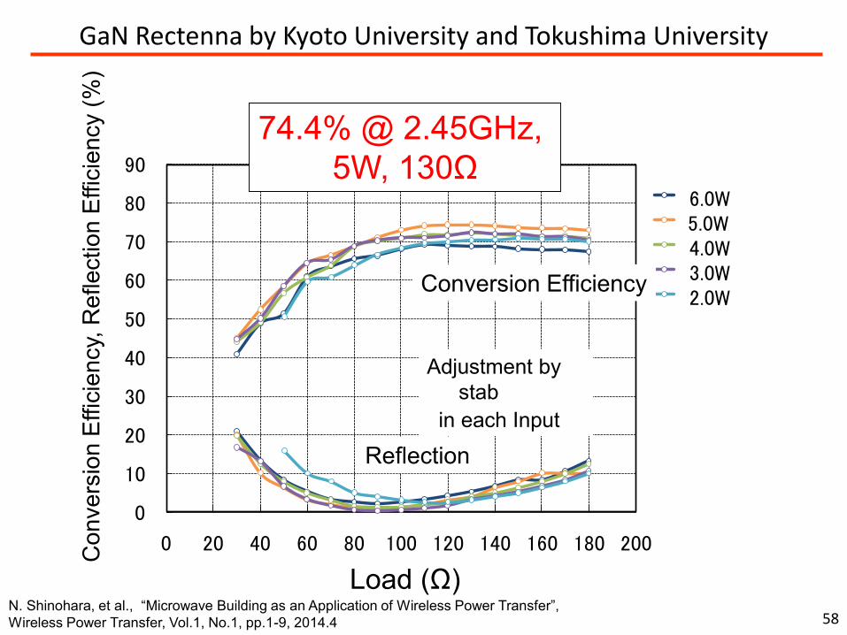
GaN Rectenna by Kyoto University and Tokushima University
GaN Schottky Diode
Microwave input DC output
Distributed Line + Capacitance for
Shingle-Shunt Full Wave Rectifier
Page 58
58
GaN Rectenna by Kyoto University and Tokushima University
0
10
20
30
40
50
60
70
80
90
0 20 40 60 80 100 120 140 160 180 200
変換
効率
、反
射率
(%
)
負荷抵抗(Ω )
整流特性/2A-6
6.0W5.0W4.0W3.0W2.0W
Load (Ω)
74.4% @ 2.45GHz,
5W, 130Ω
Adjustment by
stab
in each Input
Conversion Efficiency
Reflection
Co
nve
rsio
n E
ffic
ien
cy,
Re
fle
ctio
n E
ffic
ien
cy (
%)
N. Shinohara, et al., “Microwave Building as an Application of Wireless Power Transfer”,
Wireless Power Transfer, Vol.1, No.1, pp.1-9, 2014.4
Page 59
New GaN schottky barrier diode in 2015• GaN-SBD with AlN submount
by Sumitomo Electric Industries, LTD,
Breakdown voltage Bv [V] Junction potential Vj
[V]Zero-bias junction
capacitance Cj0 [pF]Ohmic resistance Rs
[Ω]
107 2.2 2.9 5.4
T. Nishimura, et al., “Development of High Power Rectifier of 2.45 GHz using GaN Schottky Barrier Diodes with high thermal
conductive AlN submounts”, 2015 Asian Wireless Power Transfer Workshop, 2015 59
Page 60
Simulation and Experimental RF-DC Efficiency
T. Nishimura, et al., “Development of High Power Rectifier of 2.45 GHz using GaN Schottky Barrier Diodes with high thermal
conductive AlN submounts”, 2015 Asian Wireless Power Transfer Workshop, 2015 60
Page 61
RISH, Kyoto Univ. 61
Introduction of IEEE, IEICE, ITU
61
Page 62
IEEE Microwave Theory and Techniques Society
proudly presents the
International Microwave Symposium
Honolulu, Hawaii
June 4-9, 2017
at the Hawaii Convention Center
ims2017.org
Page 63
CHAIR: Prof. Alessandra Costanzo, DEI- University of Bologna, ITALY, from May 2015 until May 2017.
VICE-CHAIRS: Naoki Shinohara, Kyoto University, Kyoto 611-0011, Japan; Ali Darwish , US Army Research Laboratory, Adelphi, MD 20708 USA
Listserv up to date? Y
Technical Highlights – WPT as one of the enabling technology for
the IoT.
– EU project proposals
– WPTC2017 in Taiwan is engaging semi-
conductor industries
– Japan activities inside ITU (International
Telecommunication Union) fixing the bands
for WPT and regulation r rules
Recent Activities Highlights– IEEE WPTC 2016, Aveiro, Portugal.
– IMS Student Design Competition on
“Wireless Energy Harvesting” has been
chaired by MTT-26 members since 2012.
More than ten competitor groups usually
apply.
– Three IMS2016 workshops
– One EuMW2016 workshop
TC Webpage is up to date
Plans/Issues for coming year– WPTC 2017, Taiwan May 11-12, 2017
– Special Issues of the Microwave Magazine
2017
– SDC for the IMS2017
– Workshops proposals for IMS2017 and
EuMW2017
MTT-26 <Wireless power
transfer and energy conversion>
63
Page 64
IEEE Wireless Power Transfer Conference (WPTc)
1st IMWS-IWPT (2011)2nd IMWS-IWPT (2012)at Kyoto, Japan
1st WPTC (2013)at Perugia, Italy
2nd WPTC (2014)at Jeju, Korea 3rd WPTC (2015)
at Boulder, USA
64
4th WPTC (2016)at Aveiro, Portugal
5th WPTC (2017)at Taipei, Taiwan
Page 65
IEEE Wireless Power Transfer Conference (WPTc2016)
Univ. of Aveiro, Portugal, May 5-6, 2016
65
Page 66
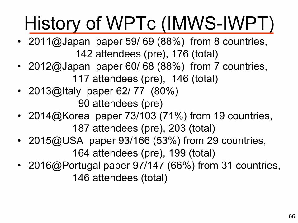
History of WPTc (IMWS-IWPT)• 2011@Japan paper 59/ 69 (88%) from 8 countries,
142 attendees (pre), 176 (total)
• 2012@Japan paper 60/ 68 (88%) from 7 countries,
117 attendees (pre), 146 (total)
• 2013@Italy paper 62/ 77 (80%)
90 attendees (pre)
• 2014@Korea paper 73/103 (71%) from 19 countries,
187 attendees (pre), 203 (total)
• 2015@USA paper 93/166 (53%) from 29 countries,
164 attendees (pre), 199 (total)
• 2016@Portugal paper 97/147 (66%) from 31 countries,
146 attendees (total)
66
Page 68
IEICE2016(Spring) Student Demonstration Competition- WPT to Flying/Moving Target -
68
March 18, 2016, 15 Demonstrations Red Line Box : Prize Winners
Page 69
WPT-assisted Flying Drone by Ristumeikan Univ.
69At IEICE2016(Spring) Student Demonstration Competition
Frequency 430MHz, 30W from 4 patch antennas
Page 70
ITU ActivitiesITU : International Telecommunication Union (Founded in 1865)
which cites the following purposes for the union: to maintain and extend international cooperation between all members of
the union for the improvement and rational use of telecommunications of all
kinds;
to promote and to offer technical assistance to developing countries in the
field of telecommunications;
to promote the development of technical facilities and their efficient
operation;
to promote the extension of the benefits of the new telecommunication
technologies to all the world's inhabitants;
to harmonize the actions of members in the attainment of these ends;
to promote, at the international level, the adoption of a broader approach to
telecommunications issues, an approach that includes other world and
regional organizations and nongovernmental organizations concerned with
telecommunications.
70
QuestionQuestion ReportReport RecommendationRecommendation RegulationRegulation
Discussion Result is published as
Page 71
Question ITU-R 210-3/1
Wireless power transmission (June, 2015)decides that the following information be gathered
1 What applications have been developed for use of WPT
technologies?
2 What are the technical characteristics of the emission employed in or
incidental to applications using WPT technologies?
3 What is the WPT’s standardization situation in the world?
decides that the following Questions should be studied
1 Under what category of spectrum use should administrations
consider WPT: ISM, or other?
2 What radio frequency bands are most suitable for WPT?
3 What steps are required to ensure that radiocommunication
services, including the radio astronomy service, are protected from
WPT operations?
71
QuestionQuestion ReportReport RecommendationRecommendation RegulationRegulation
Page 72
Discussion for Q. ITU-R 210/1 (WPT)
in Study Group 1 (SG1) - Working Party 1A (WP1A)
• 2001 : Information which was attached on SG1 Chairman’s Report
Results of contributions form US in 1997-2000
• May 2009 : SG1 Chairman’s Report Annex 14 to 1A/135-E Working document
toward a preliminary draft new report regarding Question ITU-R 210-2/1 Power
transmission via radio frequency beam (wireless power transmission)
Results of contributions form JAXA(Japan) on Feb.-May 2009
• Sep. 2009 : SG1 (Spectrum Management) Chairman’s Report
Merge of JAXA and US contributions
• 2013 : Separated reports of ‘Beam’ and ‘Non-Beam’ as a
result of contribution from Japan
• 2014 : Approval of Non-Beam WPT Report– New Report ITU-R SM.2303 - Wireless power transmission using
technologies other than radio frequency beam
• 2015 : Contribution of Beam WPT– [Beam] SG1 Chairman's report
– [Beam] Deadline of Question of BEAM WPT is expended to 2017
– [Non-Beam] Chairman’s Report (ITU-R SM.2303-1)
– [Non-Beam] Preliminary Draft of New Recommendation
– Liaison to IEC, ISO, IEEE, URSI, WIPE, WiPoT….. 72
Page 73
ITU Discussion on June, 2016
• Two Documents are submitted to ITU from Japan– PROPOSED REVISION OF THE WORKING
DOCUMENT TOWARDS A PRELIMINARY DRAFT
NEW REPORT ITU-R SM.[WPT.BEAM]
-> Toward Draft New Report
– WORK PLAN FOR WIRELESS POWER
TRANSMISSION VIA RADIO FREQUENCY BEAM
-> For Discussion of Each Applications
• Following frequency bands are listed– 915MHz band (on ISM band except in region 2)
– 2.45GHz-band (on ISM band)
– 5.8GHz band (on ISM band)
73
Done!!!
“New Report” is published
from ITU Now!http://www.itu.int/pub/R-REP-SM.2392
QuestionQuestion ReportReport RecommendationRecommendation RegulationRegulation
Page 74
WORK PLAN FOR WIRELESS POWER TRANSMISSION
VIA RADIO FREQUENCY BEAM
74
ID Applications Frequency Band Condition Distance PowerTarget years of
making reportsAppendix
a
a1
Wireless
Powered Sensor
Network
915 MHz band,
2.45 GHz band,
5.8 GHz band
Indoor, outdoorSeveral meters –
dozens of meters< 50W
[Present –
2017]
a2Wireless Charger
of Mobile Devices2.45 GHz band Indoor
Several meters –
dozens of meters< 50W [2017-2020]
b
b1Wireless Power
Transfer Sheet2.45 GHz band
In mesh-pattern
shielded sheet
Several meters
(in sheet)< 30W [2017-2020]
ARIB STD-
T113
b2 MPT in Pipe2.45 GHz band,
5.8 GHz bandIn shielded pipe
1 m – 100 m
(in pipe)< 50W [2017-2020]
b3Microwave
Buildings
2.45 GHz band,
5.8 GHz bandIn shielded pipe
1 m – 100 m
(in pipe)
50W –
5kW
[2017 – 2020
(Short Distance)]
[2020- 2030
(Long Distance)]
c
c1WPT to Moving
Flying Target
2.45 GHz band,
5.8 GHz bandOutdoor 10 m – 20 km
50W-
1MW[2025-2030]
c2Point-to-Point
WPT
2.45 GHz band,
5.8 GHz bandOutdoor 1 m – 20 km
100W –
1MW[2025-2030]
c3
Wireless
Charging for
Electric Vehicle
2.45 GHz band,
5.8G Hz bandOutdoor 0.1-10 m
100W-
100kW[2025-2030]
c4Solar Power
SatelliteTBD
Space to
ground36,000 km 1.3GW TBD
Characteristics of beam WPT applications
Page 75
RISH, Kyoto Univ. 75
Conclusion
75
Page 76
SPS
Buildings
Vehicles
Smart Energy
Communications –Power Coexistence
Energy Security
Infrastructure of Communications –Power Coexistence
Power Storage
Ubiquitous Power Source
Saving Energy
Our Dream : Wireless Power Society
Ubiquitous Power Source in Emergency
76
Page 77
Proceedings of IEEE2013.6
18 WPT Papers[Guest Editors]
K. Wu
D. Choudhury
H. Matsumoto
Online Journal of Wireless Power Transfer
Cambridge Press
http://journals.cambridge.org/action/displayJournal?jid=
wptCall for Paper!!
WPT Books
Wireless Power Transfer via Radiowaves (Wave Series)
Naoki ShinoharaISTE Publishing &
John Wiley & Sons, Inc., UK & USA2014.1
ISBN 978-1-84821-605-1(Paper Book and Kindle) 77