20
Current Status of LDACS Development Michael Schnell German Aerospace Center (DLR) www.DLR.de • Chart 1 ICAO Communications Panel 1-5 December 2014 Presentation of IP01

Current Status of LDACS Development
Michael Schnell German Aerospace Center (DLR)
www.DLR.de • Chart 1
ICAO Communications Panel 1-5 December 2014 Presentation of IP01

Motivation The Future Communications Infrastructure (FCI)
www.DLR.de • Chart 2
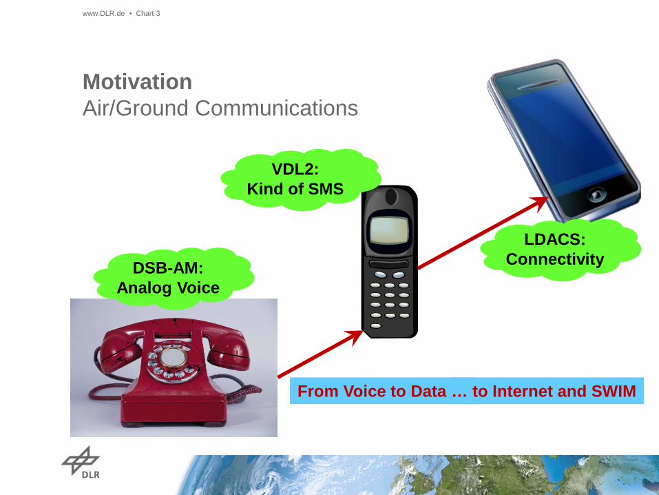
Motivation Air/Ground Communications
www.DLR.de • Chart 3
From Voice to Data …
DSB-AM: Analog Voice
VDL2: Kind of SMS
… to Internet and SWIM
LDACS: Connectivity

Outline
www.DLR.de • Chart 4
Achievements and Current Status of LDACS LDACS1 Extension Towards Navigation Conclusions Open Issues

Achievements and Current Status of LDACS Brief Review of LDACS - L-band Digital Aeronautical Communications System (LDACS) is the
future ground-based communications link within the FCI
- Two proposals: LDACS1 and LDACS2
- Deployment in L-band (960-1164 MHz)
- L-band already heavily used by - Aeronautical navigation services - Aeronautical military communications systems
- Different deployment options - Use only lower part of L-band, 960-978 MHz (LDACS2) - Use lower and upper part of L-band, 960-978 MHz / 1150-1157 MHz - Slight rearrangement of L-band assignments for radar navigation - Inlay scenario (preferred approach for LDACS1)
www.DLR.de • Chart 5

Achievements and Current Status of LDACS Brief Comparison Between LDACS1 and LDACS2 - LDACS1 can utilize more spectrum in L-band due to inlay approach; no
reorganization of spectrum assignments required
- LDACS1 is the broadband LDACS proposal (fivefold bandwidth) making available considerably more capacity
- LDACS1 applies modern communications concepts (OFDM)
- LDACS1 considerably more mature than LDACS2 - Continuous development since 2007 - Detailed evaluations of PHY and MAC layer - Receiver concept with strong robustness against interference - Numerous publications (> 30 since 2007) - Several demonstrators/prototypes available
- Europe: DLR, Frequentis AG, Rohde & Schwarz - Japan: ENRI, GNU radio implementation - China: BUAA, hardware implementation, flight testing
www.DLR.de • Chart 6

Achievements and Current Status of LDACS Potentials of LDACS1
www.DLR.de • Chart 7
- LDACS1 enables high-capacity aeronautical communications - Min. net data rate (FL+RL=overall): 291+270 = 561 kbit/s - Max. net data rate (FL+RL=overall): 1.32+1.27 = 2.59 Mbit/s - Well suited to serve modern ATM application and future needs
- Comparison with LDACS2 (overall): 70-115 kbit/s
- LDACS1 is highly flexible and scalable, enables long-term evolution - OFDM based physical layer - Scalability towards higher data rates
- LDACS1 foresees quality-of-service - Fast access to resources and low delays for application - Different priorities for different applications
- LDACS1 enables integration of navigation functionality

Achievements and Current Status of LDACS LDACS1 Work in Europe
www.DLR.de • Chart 8
SESAR JU Project P15.2.4 ATM Research
in Europe
LDACS1 Demonstrator Developed by FRQ
Compatibility Testing at DFS labs
SESAR 2020? Mature Technology, Update Specification

Achievements and Current Status of LDACS LDACS1 Work in Germany
www.DLR.de • Chart 9
DLR Internal Projects
Receiver Optimization Interference Mitigation
Receiver Concept
Demonstrator Complete Transmitter
Software Receiver

Achievements and Current Status of LDACS LDACS1 Work in Germany
www.DLR.de • Chart 10
ICONAV German National
Project with R&S as Industry Lead LDACS-COM
Hardware Implementation Including Security
LDACS-NAV DLR Internal Project
MICONAV Follow-on Project

Achievements and Current Status of LDACS LDACS1 Work Outside Europe
www.DLR.de • Chart 11
Japan ENRI (Electronic Navigation Research Institute)
LDACS1 Demonstrator Based on GNU Radio Hardware Implementation
China Beihang University (aka BUAA)
National Key Laboratory of CNS/ATM Theoretical Studies and Simulation on LDACS1
Demonstrator Implementation Preliminary Flight Tests in (May 2014)

LDACS1 Extension Towards Navigation Navigation Functionality for APNT - What is APNT? Alternative Positioning Navigation and Timing - Why APNT? For the GNSS failure case!
www.DLR.de • Chart 12
GNSS becomes primary navigation means
Navigation services require high performance
for all phases of flight Large distance
SAT-aircraft, GPS easily jammed
Newark Liberty Int’l Airport
“GPS Jammer” Personal Privacy
Device

LDACS1 Extension Towards Navigation LDACS1 as Pseudolite System
www.DLR.de • Chart 13
Continuously transmitting LDACS1 ground stations
act as pseudolites: “GPS on Ground”
Aircraft performs pseudo-range measurements towards LDACS1 ground station

LDACS1 Extension Towards Navigation Performance Bounds on Ranging With LDACS1
www.DLR.de • Chart 14
0 5 10 15 20 25
100
101
102
103
104
Carrier to Noise Ratio [dB]
Mea
n R
ange
Erro
r [m
]
Schmidl-Cox SynchronizationFreq. Domain: Synchronization SymbolsTime Domain: Synchronization SymbolsCRLB: Synchronization Symbols
~4.1 m
~4.1 m
~230 m
Theory: • Cramer Rao Lower Bound (CRLB) • Mean range error several meters
Simulations: • Slight adjustments to sync. • Theoretical bound achievable
@ reasonable C/N
Reality: • Performance in real environment? • Flight measurement campaign!

LDACS1 Extension Towards Navigation Flight Measurement Campaign
www.DLR.de • Chart 15
f/MHz 960 970
GSM
975 965 962
TAC
AN
LDAC
S A
LDAC
S B
LDAC
S C
LDAC
S D
Three flight levels: • FL100 • FL280 • FL380
LDACS – L-band Digital Aeronautical Communications System > Michael Schnell > October 2014
30 km

LDACS1 Extension Towards Navigation Range Estimation Results – Whole Flight
www.DLR.de • Chart 16
-60 -40 -20 0 20 40 600
0.02
0.04
0.06
0.08µ = 6.7 mRMSE = 15.2 m
Estimation Error [m]
Pro
babi
lity
µ = 6.7 m RMSE = 15.2 m
Raw range estimates,
averaged over 1 s time intervals

LDACS1 Extension Towards Navigation Range Estimation Results – Whole Flight
www.DLR.de • Chart 17
-60 -40 -20 0 20 40 600
0.02
0.04
0.06
0.08µ = 6.7 mRMSE = 15.2 m
Estimation Error [m]
Pro
babi
lity
µ = 6.7 m RMSE = 15.2 m
Main error source: Multipath propagation
Main error source: Troposphere
Second campaign for channel sounding
Ranging algorithms: Maximum Likelihood Doppler Smoothing
Particle Filtering
Channel modeling
Tropospheric models available
Significant reduction of bias possible

Conclusions
- LDACS1 is well-suited to serve modern ATM applications - High-capacity data link - Highly flexible and scalable
- LDACS1 has been considerably matured within the last years
- First compatibility investigations (LDACS1 DME) have been
performed
- LDACS1 offers an excellent opportunity for extension towards navigation - APNT service on top of communications infrastructure - Theoretical ranging performance in the order of meters - Measurement campaign validates navigation performance for APNT
www.DLR.de • Chart 18

Open Issues
- Further L-band compatibility evaluations for LDACS1 - DME/TACAN, UAT, SSR Mode S - Military communications systems (JTIDS)
- Development of deployment concept for LDACS1
- Development of a migration strategy from VDL2 to LDACS1
- Development of final LDACS1 specification including technology
amendments as required and initiation of standardization
- Development of fully functional LDACS1 prototype and flight testing
www.DLR.de • Chart 19

www.DLR.de • Chart 20
Thank You! More about LDACS1
www.ldacs.com


