EUPAVE Webinar Presentation By: Mark B. Snyder, Ph.D., P.E. – PERC, LLC CURRENT U.S. PRACTICES FOR SUCCESSFUL DESIGN AND CONSTRUCTION OF CONCRETE OVERLAYS Engineering consultant to the U.S. National Concrete Pavement Technology Center and American Concrete Pavement Association May 19, 2020
1.2m x 1.2m Panels:Corner Breaks due to Wheel Loadings
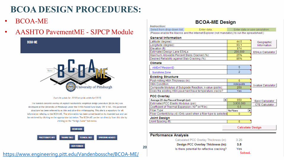
Design(Thickness – Length x Width)
Panels Cracked
(%)
Corner Cracks
100mm – 1.2m x 1.2m 5 6
75mm – 1.2m x 1.2m 40 165
75mm – 1.5m x 1.8m 8 17
150mm – 1.5m x 1.8m 0 0
150mm – 3m x 3.7m – No dowels 13 0
150mm – 3m x 3.7m – Dowels 3 0
BCOA JOINT LAYOUTKEEP LONGITUDINAL JOINTS OUT OF WHEEL PATHS!
75mm PCC over 250mm AC,1.2m x 1.2m panels, 6 yrs (~6M ESALs)
75mm PCC over 250mm AC,1.8m x 1.8m panels, 6 yrs (~6M ESALs)
18
BEST BCOA JOINTING PRACTICESMaximum Panel Size = 18-24 x Slab Thickness• For overlay thickness <75mm, typically use 1m sq.• For overlay thickness = 75 – 150mm, typically use 2m sq.Usually No Dowels• Small panel size increases effectiveness of aggregate interlock• Thickness (dowel cover) concerns
- 25mm diameter dowels have been used in 150mm thick concrete overlays with mixed results
- Longitudinal joint ties have been used successfully when thickness > 4 in.
- Structural fibers may be effective “ties” between lanesLongitudinal Joints Should be “Tied” if Possible
- Small tie bars have been used successfully when overlay thickness > 100mm
- Structural fibers may effectively “tie” lanes and prevent excessive joint opening
19
BCOA STRUCTURAL FIBER CONSIDERATIONS
Does not increase concrete strengthIncreases toughness, post-crack integrity
• Mill and clean surface.• Pre-overlay repairs, if required.• Set forms for roller screed.• Prepare surface.• Place concrete.• Texture pavement.• Apply curing compound.• Saw cut joints.• Monitor strength gain (maturity).
22
BCOA SURFACE PREPARATION
Mill AC Surface (optional)• Remove rutting• Restore profile (remove high spots)• Enhance bond• Minimum 75mm AC remaining after
millingCan place without milling if rutting <50mm• Results in variable overlay thickness
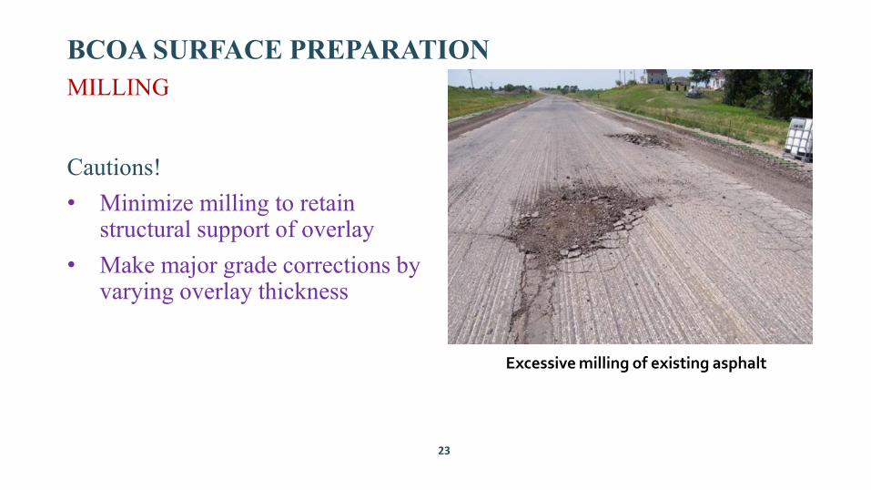
MILLING
23
BCOA SURFACE PREPARATIONMILLING
Cautions!• Minimize milling to retain
structural support of overlay• Make major grade corrections by
varying overlay thickness
Excessive milling of existing asphalt
24
BCOA SURFACE PREPARATIONCLEANING THE SURFACE
Power-broom• Remove loose material• Allow inspection to determine
need for pre-overlay repairs
25
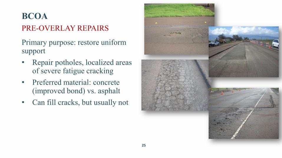
BCOAPRE-OVERLAY REPAIRS
Primary purpose: restore uniform support• Repair potholes, localized areas
of severe fatigue cracking• Preferred material: concrete
(improved bond) vs. asphalt• Can fill cracks, but usually not
26
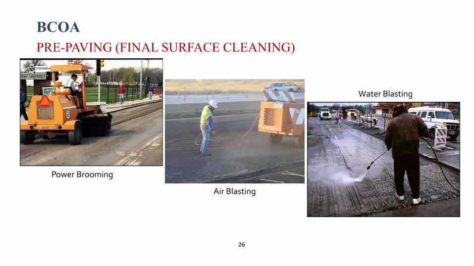
BCOAPRE-PAVING (FINAL SURFACE CLEANING)
Power Brooming
Air Blasting
Water Blasting
27
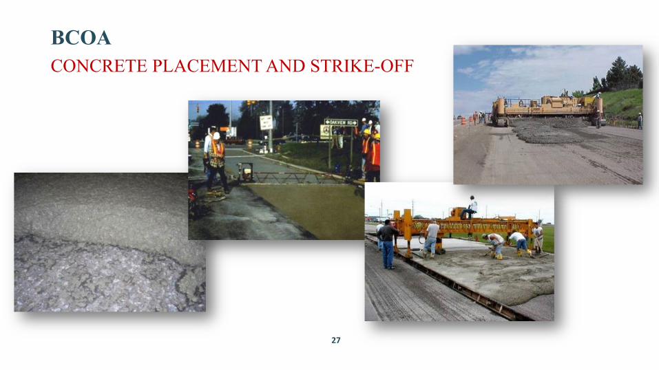
BCOACONCRETE PLACEMENT AND STRIKE-OFF
28
BCOA - FINISHING
5-m float for smoothness
Need for finishing is minimized by:
• Selecting a workable mix
• Operating the paving equipment properly
29
BCOA – SURFACE TEXTURING
Tines – 19mm spacing
Longitudinal Tining
Longitudinal Brushing
Artificial Turf Drag
30
BCOA CURING
Keys for success:• Apply when surface sheen is gone• High application rate (0.27 – 0.36
liters/m2)• Cover all exposed surfaces
(including sides)• Automated equipment provides
most reliable coverage• Check spray nozzles frequently
• Minimum cure time 72 – 96 hrs
Good!
Good!
Bad!
31
BCOA JOINT SAWING
Saw cut depth = D/3 (typical)• Less for early-entry saws• Adjust cut depth for slab
thickness (especially for variable thickness overlays)
Timely sawing is critical!• More joints = need for more
equipment, operators and spare parts!
32
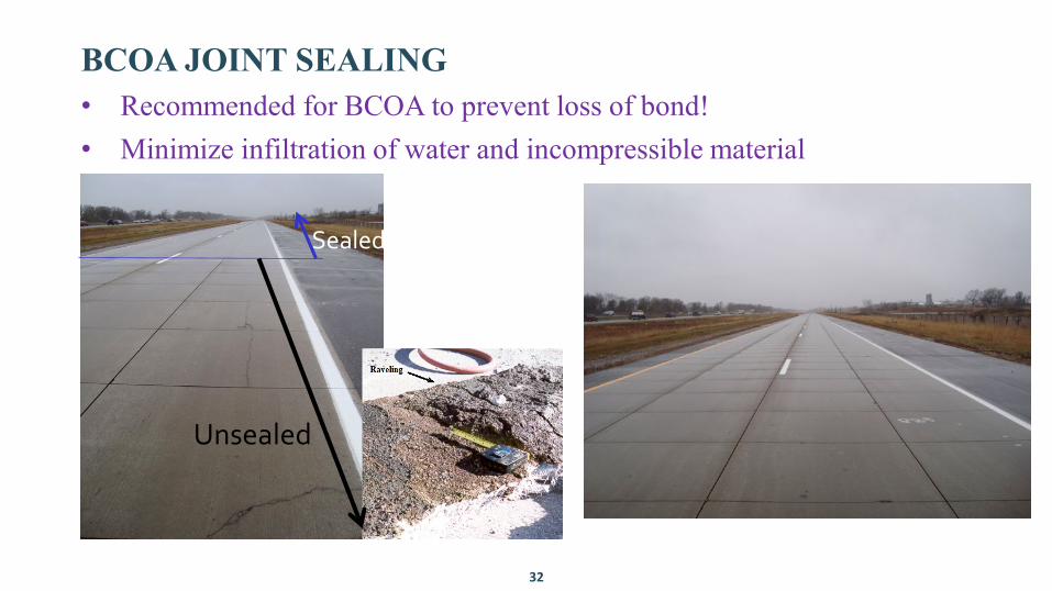
BCOA JOINT SEALING• Recommended for BCOA to prevent loss of bond!• Minimize infiltration of water and incompressible material
Sealed
Unsealed
UNBONDED CONCRETE OVERLAYS
34
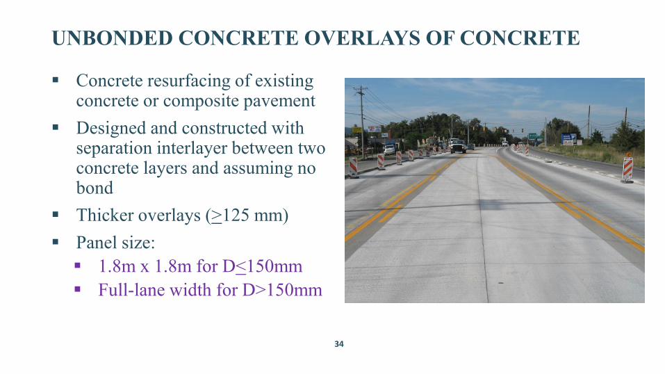
UNBONDED CONCRETE OVERLAYS OF CONCRETE
Concrete resurfacing of existing concrete or composite pavement
Designed and constructed with separation interlayer between two concrete layers and assuming no bond
Thicker overlays (>125 mm) Panel size: 1.8m x 1.8m for D<150mm Full-lane width for D>150mm
• Develop preliminary designs (thickness, base designs, joint spacing, and other design features).
• Use software to evaluate predicted performance over the analysis period (e.g., 50 years).
• Determine life-cycle activity profiles (“what” rehabilitation activities to perform and “when”).
• Calculate the Initial and Life Cycle Costs for each pavement design over the analysis period.
• Evaluate designs and modify as needed to develop a pavement section that meets or exceeds the required initial performance period and has the lowest life cycle cost.
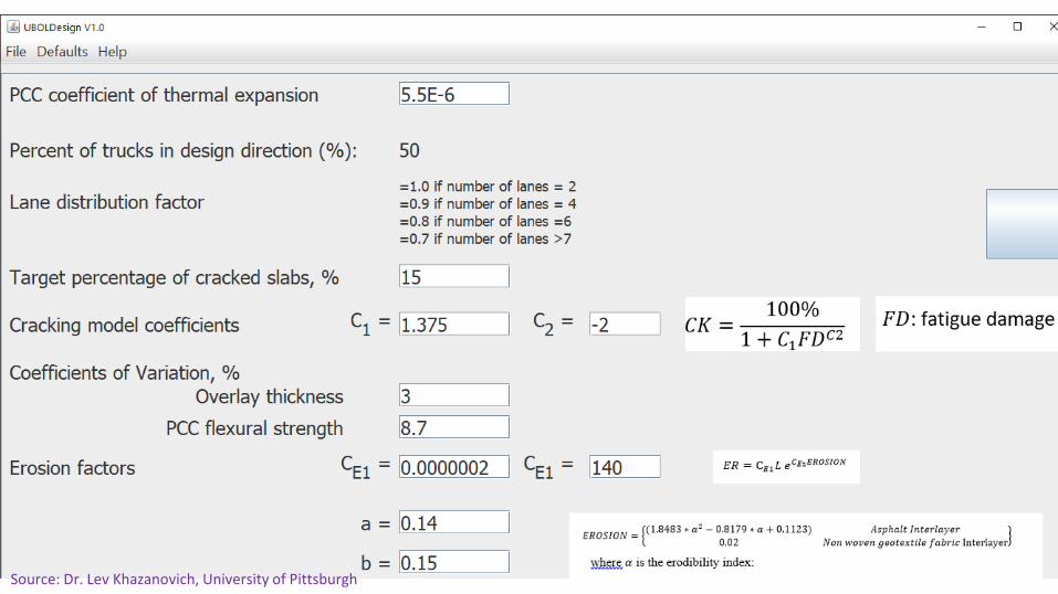
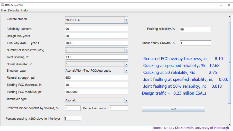
UBOL Design Version 1.0
• New mechanistic-empirical unbonded overlay design procedure.
• Developed at University of Pittsburgh under pooled-fund study by several state highway agencies.
• Structural analysis simulates FEM models using neural network for quick, inexpensive results.
• Performance models are based on data obtained from unbonded concrete overlays throughout the U.S.
• Can be used to evaluate trial designs or to develop designs based on input performance parameters.
• Public domain (“free”) software.
Source: Dr. Lev Khazanovich, University of Pittsburgh
Source: Dr. Lev Khazanovich, University of Pittsburgh
Source: Dr. Lev Khazanovich, University of Pittsburgh
UNBONDED OVERLAYS OF CONCRETE PAVEMENTPRE-OVERLAY REPAIRS
KEYS TO SUCCESS
• Full-depth repairs are required only where structural integrity is lost at isolated spots.
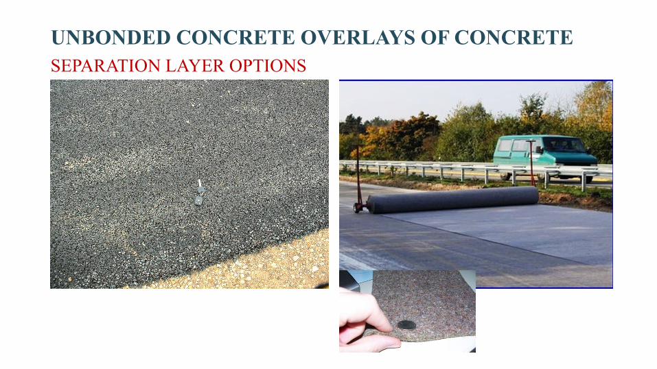
• Separator layer to isolate overlay from underlying pavement -minimize reflective cracking.
• 25-50 mm dense- or open-graded asphalt
• Drainage or anti-strip for heavy traffic
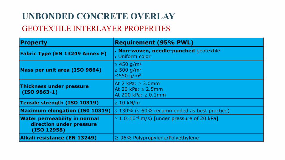
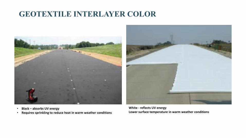
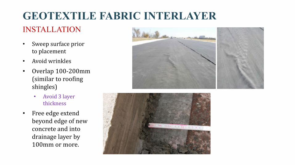
• Geotextile fabric
UNBONDED OVERLAYS OF CONCRETE PAVEMENT
• Shorter joint spacing helps minimize curling and warping stresses.
• Transverse joints at 18-24 times thickness to maximum of ~5m
• No need to match joints with those of the underlying concrete pavement.
UNBONDED CONCRETE OVERLAYS OF CONCRETESEPARATION LAYER OPTIONS
RESOURCE:NATIONAL CONCRETE OVERLAY EXPLORER DATABASE –EXAMPLE DATASET
58
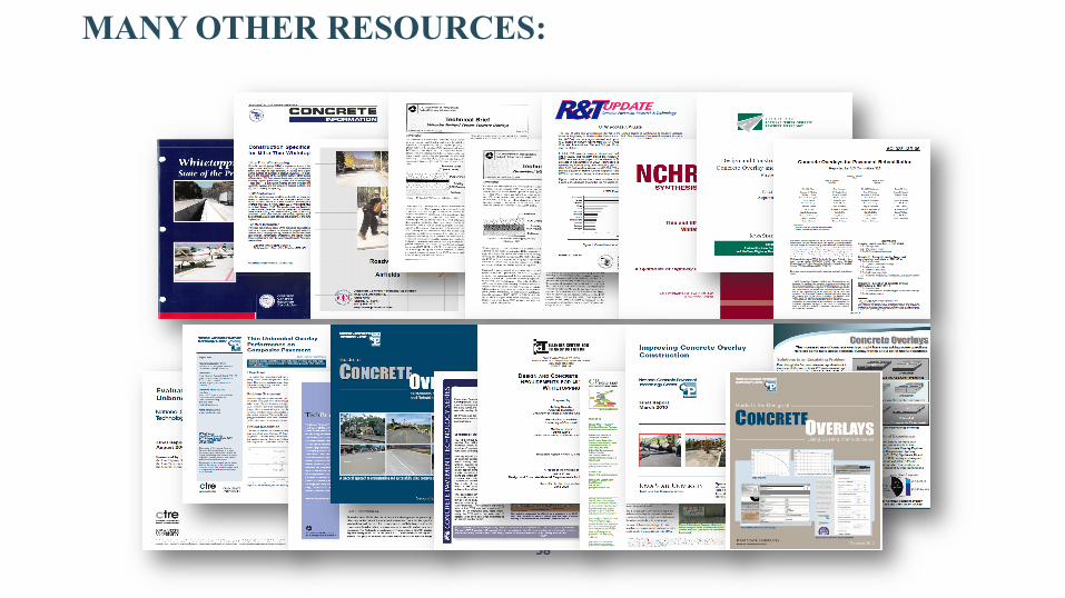
MANY OTHER RESOURCES:
59
ACKNOWLEDGMENTS
Dr. Shiraz Tayabji (Fugro Consultants, Inc.) Mr. Kurt Smith (Applied Pavement Technology, Inc.) U.S. National Concrete Pavement Technology Program (CPTP) Mr. Dale Harrington (National Center for Concrete Pavement Technology) Mr. Gary Fick (Transtec, Inc.) Dr. Julie Vandenbossche (University of Pittsburgh) Mr. Tom Burnham (Minnesota DOT) Dr. Lev Khazanovich (University of Pittsburgh) American Concrete Pavement Association
MARK B. SNYDER
PAVEMENT ENGINEERING AND RESEARCH CONSULTANTS (PERC), LLC