Page 1
M. E - Power Systems Engineering
(Regulation 2019)
FRANCIS XAVIER ENGINEERING COLLEGE
TIRUNELVELI
CURRICULUM &
SYLLABI
VISION "To be a Centre of
Excellence for Technology transformation in the field
of Electrical and Electronics Engineering"
MISSION 1. To empower the vibrant young
leaders with technical skills and knowledge in the field of technology
2. To facilitate the industries to adopt effective solutions in the field of Electrical and Electronics Engineering through consultancy
3. To transform technology for rural needs.
Page 2
PROGRAM EDUCATIONAL OBJECTIVES (PEOS)
i. To prepare the students to have career in the electrical power industry/research
organization/teaching.
ii. To provide good foundation in mathematics and computational technology to analyze and
solve problems encountered in electrical power industry.
iii. Pursue lifelong learning and continuous improvement of their knowledge in the electrical
power industry.
iv. To understand the national and global issues related to the electrical power industry and
to be considerate of the impact of these issues on the environment and within different
cultures.
v. Apply the highest professional and ethical standards to their activities in the electrical
power industry.
vi. To provide the students with knowledge to be involved with the technology
advancements and future developments in power generation, control and management as
well as with alternate and new energy resources.
PROGRAM OUTCOMES (POs)
On successful completion of the programme,
1. Graduates will be able to demonstrate the principles and practices of the electrical power
industry regarding generation, transmission, distribution and electrical machines and their
controls.
2. Graduates will be able to apply their knowledge of electrical power principles, as well as
mathematics and scientific principles, to new applications in electrical power.
3. Graduates will be able to perform, analyze, and apply the results of experiments to
electrical power application improvements.
4. Graduates will be able to look at all options in design and development projects and
creativity and choose the most appropriate option for the current project.
Page 3
5. Graduates will function effectively as a member of a project team.
6. Graduates will be able to identify problems in electrical power systems, analyze the
problems, and solve them using all of the required and available resources.
7. Graduates will be able to effectively communicate technical project information in
writing or in personal presentation and conversation.
8. Graduates will be engaged in continuously learning the new practices, principles, and
techniques of the electrical power industry.
9. Graduates will work on application software packages for power system analysis and
design.
10. Graduates will develop indigenous software packages for power system planning and
operational problems of utilities.
MAPPING OF PROGRAMME EDUCATIONAL OBJECTIVES WITH
PROGRAMME OUTCOMES
Program
Education
al
Objective
PROGRAMME OUTCOMES
PO1 PO2 PO3 PO4 PO5 PO6 PO7 PO8 PO9 PO10
i X X X X X X X X X X
ii X X X X X X X X
iii X
iv X X X X X X
v X X X X X
vi X X X X X X X X
Page 4
FRANCIS XAVIER ENGINEERING COLLEGE, TIRUNELVELI
M. E –POWER SYSTEMS ENGINEERING
CHOICE BASED CREDIT SYSTEM
I TO IV SEMESTERS CURRICULUM & SYLLABI
SEMESTER - I
FIRST SEMESTER
Code No. Course Category L T P C H
19MA1253 Applied Mathematics for Electrical
Engineers BS 3 1 0 4 4
19PS1601
Analysis and Computation of
Electromagnetic Transients in Power
Systems
PC 3 0 0 3 3
19PS1602 Power System Modeling and Analysis PC 3 1 0 4 4
19PS1603 Power System Operation and Control PC 3 0 0 3 3
19PE1605 System Theory PC 3 1 0 4 4
Professional Elective I PE 3 0 0 3 3
19PS1611 Power System
Simulation Laboratory PC 0 0 4 2 4
TOTAL 18 3 4 23 25
SECOND SEMESTER
Code No. Course Category L T P C H
19PS2601 Digital Protection for PowerSystem PC 3 0 0 3 3
19PS2602 Power System Dynamics and stability PC 3 0 0 3 3
19PS2603 Restructured Power System PC 3 0 0 3 3
19PE2705 Flexible AC Transmission Systems PC 3 0 0 3 3
Professional Elective II PE 3 0 0 3 3
Professional Elective III PE 3 0 0 3 3
19PS2611 Advanced Power System Simulation
Laboratory PC 0 0 4 2 4
19PS2911 Technical Seminar EEC 0 0 2 1 2
TOTAL 18 0 6 21 24
.
Page 5
THIRD SEMESTER
Code No. Course Category L T P C H
Professional Elective IV PE 3 0 0 3 3
Professional Elective V PE 3 0 0 3 3
Professional Elective VI PE 3 0 0 3 3
19PS3911 Project Work Phase I EEC 0 0 12 6 12
TOTAL 09 0 12 15 21
FOURTH SEMESTER
Code No. Course Categor
y L T P C H
19PS4911 Project Work Phase II EEC 0 0 24 12 24
TOTAL 0 0 24 12 24
Total Credits :71
Code No. Course L T P C
PROFESSIONAL ELECTIVES
PROFESSIONAL ELECTIVE I- SEMESTER I
19PE1603 Modeling and Analysis of Electrical Machines 3 0 0 3
19PE1604 Solar and Energy Storage Systems 3 0 0 3
19PE2704 Soft Computing Techniques 3 0 0 3
3 0 0 3
PROFESSIONAL ELECTIVE II&III - SEMESTER II
19PE3707 Smart Grid 3 0 0 3
19PE1602 Analysis and Design of Power Converters and Inverters 3 0 0 3
19PS2701 Power System Reliability 3 0 0 3
19PE3701 High Voltage Direct Current Transmission 3 0 0 3
19PE2709 Distributed Generation and Microgrid 3 0 0 3
19PS2702 Industrial Power System Analysis and Design 3 0 0 3
PROFESSIONAL ELECTIVE IV, V & VI - SEMESTER III
19PS3701 Electrical Distribution System 3 0 0 3
Page 6
Code No. Course L T P C
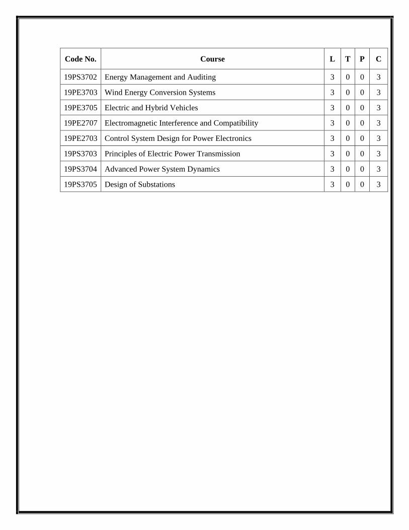
19PS3702 Energy Management and Auditing 3 0 0 3
19PE3703 Wind Energy Conversion Systems 3 0 0 3
19PE3705 Electric and Hybrid Vehicles 3 0 0 3
19PE2707 Electromagnetic Interference and Compatibility 3 0 0 3
19PE2703 Control System Design for Power Electronics 3 0 0 3
19PS3703 Principles of Electric Power Transmission 3 0 0 3
19PS3704 Advanced Power System Dynamics 3 0 0 3
19PS3705 Design of Substations 3 0 0 3
Page 7
19MA1253 APPLIED MATHEMATICS FOR ELECTRICAL
ENGINEERS L T P C
3 1 0 4
COURSE OBJECTIVES:
• The main objective of this course is to demonstrate various analytical skills in applied
mathematics and extensive experience with the tactics of problem solving and logical
thinking applicable for the students of electrical engineering.
• This course also will help the students to identify, formulate, abstract, and solve problems
in electrical engineering using mathematical tools from a variety of mathematical areas,
including matrix theory, calculus of variations, probability, linear programming and
Fourier series.
PRE-REQUISITE:
UG level Mathematics
UNIT I MATRIX THEORY 12
Cholesky decomposition-Generalized Eigenvectors-Canonical basis-QR Factorization-Least
squares method-Singular value decomposition
UNIT II CALCULUS OF VARIATIONS 12
Concept of variation and its properties–Euler’s equation–Functional dependant on first and
higher order derivatives–Functionals dependant on functions of several independent variables–
Variational problems with moving boundaries–Isoperimetric problems-Direct methods : Ritz and
Kantorovich methods.
UNIT III PROBABILITY AND RANDOM VARIABLES 12
Probability–Axioms of probability–Conditional probability–Baye’s theorem-Random variables-
Probability function–Moments–Moment generating functions and their properties–Binomial,
Poisson, Geometric, Uniform, Exponential, Gamma and Normal distributions–Function of a
random variable.
UNIT IV LINEAR PROGRAMMING 12
Formulation–Graphical solution–Simplex method–Big M method-Two phase method-
Transportation and Assignment models.
Page 8
UNIT V FOURIER SERIES 12
Fourier trigonometric series : Periodic function as power signals–Convergence of series–Even
and odd function : Cosine and sine series–Non periodic function : Extension to other intervals-
Power signals : Exponential Fourier series–Parseval’s theorem and power spectrum–Eigen value
problems and orthogonal functions–Regular Sturm-Liouville systems–Generalized Fourier
series.
TOTAL PERIODS : 60
REFERENCES :
1. Andrews L.C. and Phillips R.L., "Mathematical Techniques for Engineers and
Scientists",Prentice Hall of India Pvt. Ltd., New Delhi, 2005.
2. Bronson, R. “Matrix Operation”, Schaum’s outline series, 2ndEdition, McGraw Hill,
2011.
3. Elsgolc, L. D. "Calculus of Variations", Dover Publications, New York, 2007.
4. Johnson, R.A., Miller, I and Freund J., "Miller and Freund’s Probability and Statistics
forEngineers", Pearson Education, Asia, 8thEdition, 2015.
5. O'Neil, P.V., "Advanced Engineering Mathematics", Thomson Asia Pvt. Ltd., Singapore,
2003.
6. Taha, H.A., “Operations Research, An Introduction”,9thEdition, Pearson education,
NewDelhi, 2016.
WEB RESOURCES:
• https://nptel.ac.in/courses/111102012/
COURSE OUTCOMES:
After completing this course, students should demonstrate competency in the following skills:
CO No COURSE OUTCOMES
CO101.1 Apply various methods in matrix theory to solve system of linear
equations.
CO101.2 Maximizing and minimizing the functional that occur in electrical
engineering discipline.
CO101.3 Computation of probability and moments, standard distributions of
discrete and continuous random variables and functions of a random
Page 9
variable.
CO101.4
Could develop a fundamental understanding of linear programming
models, able to develop a linear programming model from problem
description, apply the simplex method for solving linear programming
problems.
CO101.5 Fourier series analysis and its uses in representing the power signals
POs Vs COs Mapping:
COs PO1 PO2 PO3 PO4 PO5 PO6 PO7 PO8 PO9 PO10
CO101.1 3 3 2
CO101.2 3 3 2
CO101.3 3 3 2
CO101.4 3 3 2
CO101.5 3 3 2
1→Low 2→Medium 3→High
19PS1601
ANALYSIS AND COMPUTATION OF
ELECTROMAGNETIC
TRANSIENTS IN POWER SYSTEMS
L T P C
3 0 0 3
OBJECTIVES:
• To understand the various types of transients and its analysis in power system.
• To learn about modeling and computational aspects transient’s computation
• To understand the parameters and modeling of underground cables.
• To understand the modeling of power system for transient over voltages.
• Electromagnetic Transient Program (EMTP).
PRE-REQISITE:
• Electromagnetic Theory
• Electrical Transients
Page 10
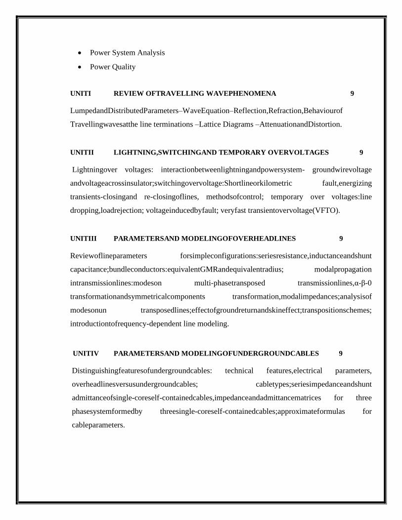
• Power System Analysis
• Power Quality
UNITI REVIEW OFTRAVELLING WAVEPHENOMENA 9
LumpedandDistributedParameters–WaveEquation–Reflection,Refraction,Behaviourof
Travellingwavesatthe line terminations –Lattice Diagrams –AttenuationandDistortion.
UNITII LIGHTNING,SWITCHINGAND TEMPORARY OVERVOLTAGES 9
Lightningover voltages: interactionbetweenlightningandpowersystem- groundwirevoltage
andvoltageacrossinsulator;switchingovervoltage:Shortlineorkilometric fault,energizing
transients-closingand re-closingoflines, methodsofcontrol; temporary over voltages:line
dropping,loadrejection; voltageinducedbyfault; veryfast transientovervoltage(VFTO).
UNITIII PARAMETERSAND MODELINGOFOVERHEADLINES 9
Reviewoflineparameters forsimpleconfigurations:seriesresistance,inductanceandshunt
capacitance;bundleconductors:equivalentGMRandequivalentradius; modalpropagation
intransmissionlines:modeson multi-phasetransposed transmissionlines,α-β-0
transformationandsymmetricalcomponents transformation,modalimpedances;analysisof
modesonun transposedlines;effectofgroundreturnandskineffect;transpositionschemes;
introductiontofrequency-dependent line modeling.
UNITIV PARAMETERSAND MODELINGOFUNDERGROUNDCABLES 9
Distinguishingfeaturesofundergroundcables: technical features,electrical parameters,
overheadlinesversusundergroundcables; cabletypes;seriesimpedanceandshunt
admittanceofsingle-coreself-containedcables,impedanceandadmittancematrices for three
phasesystemformedby threesingle-coreself-containedcables;approximateformulas for
cableparameters.
Page 11
UNITV COMPUTATION OFPOWER SYSTEMTRANSIENTS 9
Digitalcomputationof lineparameters:Need oflineparameter evaluation programs,salient
featuresofatypicallineparameterevaluationprogram;constructional featuresofthataffect
transmissionlineparameters; lineparameters forphysicalandequivalentphaseconductors
eliminationofground wires bundlingofconductors;principleofdigitalcomputationof
transients:featuresandcapabilitiesofelectromagnetictransientsprogram;steady stateand
timestepsolutionmodules:basicsolutionmethods;casestudiesonsimulationofvarious
typesoftransients.
TOTAL :45 PERIODS
REFERENCES
1. Allan Greenwood, “Electrical Transients in Power System”, Wiley & Sons Inc.
New York, 1991.
2. R. Ramanujam, “Computational Electromagnetic Transients: Modeling, Solution
Methods and Simulation”, I.K. International Publishing House Pvt. Ltd, New
Delhi, 2014.
3. Naidu M S and Kamaraju V, “High Voltage Engineering”, Tata McGraw-Hill
Publishing Company Ltd., New Delhi, 2004
WEB RESOURCES:
• https://www.researchgate.net/publication/224716926_Computation_of_power_sy
stem_transients_Overview_and_challenges
• https://onlinelibrary.wiley.com/doi/10.1002/9781118694190.ch1
• http://www.srmvalliammai.ac.in/questionbank-meps.html
• https://epd.wisc.edu/courses/analysis-of-transients-in-power-systems/
COURSE OUTCOMES:
CO No COURSE OUTCOMES
CO102.1 Able to model overhead lines, cables and transformers.
CO102.2 Able to analyze power system transients.
Page 12
CO102.3 Able to modelling of underground cables.
CO102.4 Able to modeling of power system for transient over voltages.
CO102.5 Familiarize in using Electromagnetic Transient Program
POs Vs COs MAPPING:
CO No PO1 PO2 PO3 PO4 PO5 PO6 PO7 PO8 PO9 PO10 PO11 PO12
CO102.1 3 1
CO102.2 2 3
CO102.3 3 1 3 2
CO102.4 2 2 3 3 2 2
CO102.5 2 3 3 3 2 3
1→Low 2→Medium 3→High
19PS1602 POWER SYSTEM MODELLING AND ANALYSIS L T P C
4 0 0 4
OBJECTIVES:
• To discuss different techniques dealing with sparse matrix for large scale power systems.
• To explain different methods of power flow solutions.
• To solve optimal power flow problem.
• To analyze various types of short circuit faults analysis and understand the consequence of
different type of faults.
• To demonstrate different numeric al integration methods and factors influencing transient
stability.
PRE-REQISITE:
• Transmission and Distribution
• Power Plant Engineering
• High Voltage Engineering
• Power System Analysis
Page 13
UNIT I SOLUTION TECHNIQUE 9
Sparse Matrix techniques for large scale power systems: Optimal ordering schemes for
preserving sparsity. Flexible packed storage scheme for storing matrix as compact arrays –
Factorization by Bi factorization and Gauss elimination methods; Repeat solution using Left and
Right factors and L and U matrices.
UNIT II POWER FLOW ANALYSIS 9
Power flow equation in real and polar forms; Review of Newton‟s method for solution;
Adjustment of P-V buses; Review of Fast Decoupled Power Flow method; Sensitivity factors for
P-V bus adjustment.
UNIT III OPTIMAL POWER FLOW 9
Problem statement; Solution of Optimal Power Flow (OPF) – The gradient method, Newton‟s
method, Linear Sensitivity Analysis; LP methods – With real power variables only – LP method
with AC power flow variables and detailed cost functions Security constrained Optimal Power
Flow; Interior point algorithm; Bus Incremental costs.
UNIT IV SHORT CIRCUIT ANALYSIS 9
Formation of bus impedance matrix with mutual coupling (single phase basis and three phase
basis) - Computer method for fault analysis using ZBUS and sequence components. Derivation
of equations for bus voltages, fault current and line currents, both in sequence and phase –
symmetrical and unsymmetrical faults.
UNITV TRANSIENTSTABILITYANALYSIS 9
Introduction, Numerical Integration Methods: Euler and Fourth Order Runge-Kutta methods,
Algorithm for simulation of SMIB and multi-machine system with classical synchronous
machine model; Factors influencing transient stability, Numerical stability and implicit
Page 14
Integration methods.
L:45 +T: 15 TOTAL:60 PERIODS
1. B.W Williams ‘Power Electronics Circuit Devices and Applications’..
2. A.J.Wood and B.F.Wollenberg, “Power Generation Operation and Control”, John
Wiley and sons, New York, 1996.
3. W.F.Tinney and W.S.Meyer, “Solution of Large Sparse System by Ordered Triangular
Factorization” IEEE Trans. on Automatic Control, Vol : AC-18, pp:333- 346, Aug 1973.
4. K.Zollenkopf, “Bi-Factorization: Basic Computational Algorithm and Programming
Techniques; pp:75-96 ; Book on “Large Sparse Set of Linear Systems” Editor:
J.K.Rerd,Academic Press, 1971.
5. M.A.Pai,” Computer Techniques in Power System Analysis”,Tata McGraw-Hill
Publishing Company Limited, New Delhi, 2006.
6. G W Stagg , A.H El. Abiad, “Computer Methods in Power System Analysis”, McGraw
Hill, 1968.
7. P.Kundur, “Power System Stability and Control”, McGraw Hill, 1994.
WEB RESOURCES:
• https://presentgroup.com.au/power-system-modelling-and-analysis/
• https://www.osti.gov/servlets/purl/1083672
• https://link.springer.com/chapter/10.1007/978-3-319-02393-9_2
• https://www.engineersaustralia.org.au/Event/power-system-modelling-and-analysis-
presentation
• https://www.academia.edu/25013211/Modelling_and_Analysis_of_Electric_Power_Syste
ms_Power_Flow_Analysis_Fault_Analysis_Power_Systems_Dynamics_and_Stability
• http://www.optimisedenergysolutions.com/services-modellingandanalysis.aspx
COURSE OUTCOMES:
CO No COURSE OUTCOMES
CO103.1 Ability to apply the concepts of sparse matrix for large scale power
Page 15
system analysis.
CO103.2 Ability to analyze power system studies that needed for the transmission
system planning.
CO103.3 Able to solve optimal power flow problems.
CO103.4 Able to analyse short circuit faults and understand the consequence faults.
CO103.5 Ability to understand AI integration methods and factors influencing
transient stability.
POs Vs COs MAPPING:
CO No PO1 PO2 PO3 PO4 PO5 PO6 PO7 PO8 PO9 PO10 PO11 PO12
CO103.1 3 2
CO103.2 2 3 3 1
CO103.3 1 2 3 3 2 2
CO103.4 2 2 2 2 2
CO103.5 2 2 2 2
1→Low 2→Medium 3→High
19PS1603 POWER SYSTEM OPERATION AND CONTROL L T P C
3 0 0 3
OBJECTIVES:
• To understand the fundamentals of speed governing system and the concept of control
areas.
• To provide knowledge about Hydrothermal scheduling, Unit commitment and solution
techniques.
• To impart knowledge on the need of state estimation and its role in the day- today
operation of power system.
Page 16
PRE-REQISITE:
• POWER SYSTEM ANALYSIS
• CONTROL SYSTEM
• POWER PLANT ENGINEERING
UNITI INTRODUCTION 9
Systemload variation:Systemload characteristics,load curves-daily,weekly and annual, load-
durationcurve,load factor,diversity factor.Reserverequirements: Installedreserves,
spinningreserves,coldreserves,hotreserves.Overview ofsystemoperation:Load forecasting,
techniquesof forecasting, basicsofpowersystemoperationandcontrol.
UNITII REALPOWER- FREQUENCYCONTROL 9
Fundamentals ofspeed governingmechanismand modelling:Speed-load characteristics–
Loadsharingbetween twosynchronous machinesinparallel;conceptofcontrol area,LFC
controlofa single-area system:Staticanddynamicanalysisofuncontrolledandcontrolled
cases,EconomicDispatchControl.Multi-areasystems:Two-area systemmodelling;static
analysis,uncontrolledcase;tielinewithfrequency biascontroloftwo-areasystemderivation.
UNITIII HYDROTHERMALSCHEDULINGPROBLEM 9
Hydrothermal schedulingproblem: shorttermandlong term-mathematical model,algorithm.
Dynamic programming solution methodology for Hydro-thermal scheduling with pumped
hydroplant: Optimizationwithpumpedhydroplant-Schedulingofsystems withpumped hydro
plantduringoff-peakseasons:algorithm.Selectionofinitialfeasibletrajectory forpumped
hydroplant-Pumpedhydroplantasspinningreserveunit-generationof outageinduced constraint.
UNITIV UNIT COMMITMENTAND ECONOMIC DISPATCH 9
StatementofUnitCommitment(UC)problem;constraintsinUC:spinningreserve,thermal unit
constraints, hydro constraints, fuelconstraints and other constraints; UC solution
methods:Priority-listmethods, forwarddynamic programmingapproach,numericalproblems.
Incrementalcostcurve,co-ordinationequations withoutlossandwithloss,solutionby direct
methodandλ-iteration method.Basepointandparticipation factors.-Economicdispatch controller
addedtoLFCcontrol.
Page 17
UNITV STATEESTIMATION 9
Need forpowersystemstateestimation-Networkobservability –DCstate estimation model- State
estimation ofpowersystem–Methods ofstate estimation:Leastsquare state estimation,
Weightedleastsquarestateestimation,Maximumlikelihood-Baddatadetection andidentification.
TOTAL:45 PERIODS
REFERENCE(S):
1. Olle. I. Elgerd, “Electric Energy Systems Theory – An Introduction”, Tata McGraw Hill
Publishing Company Ltd, New Delhi, Second Edition, 2003.
2. D.P. Kothari and I.J. Nagrath, “Modern Power System Analysis”, Third Edition, Tata
McGraw Hill Publishing Company Limited, New Delhi, 2003.
3. L.L. Grigsby, “The Electric Power Engineering, Hand Book”, CRC Press & IEEE
Press,2001.
4. Allen.J.Wood and Bruce F.Wollenberg, “Power Generation, Operation and Control”,
John Wiley & Sons, Inc., 2003.
5. P. Kundur, “Power System Stability & Control”, McGraw Hill Publications, USA, 1994.
WEB SOURCE(S):
1. https://nptel.ac.in/courses/108/101/108101040/
2. http://www.crectirupati.com/sites/default/files/lecture_notes/PSOC%20-%20%20IV%20-
%20EEE_0.pdf
COURSE OUTCOMES:
CO104.1 Learners will be able to understand system load variations and get an
overview of power system operations.
CO104.2 Learners will be exposed to power system state estimation.
CO104.3 Learners will attain knowledge about hydrothermal scheduling.
CO104.4 Learners will understand the significance of unit commitment and different
solution methods.
CO104.5 Learners will understand the need for state estimation in real time operation
Page 18
POs Vs COs MAPPING:
Cos PO1 PO2 PO3 PO4 PO5 PO6 PO7 PO8 PO9 PO10
CO104.1 2 2 2 1 2
CO104.2 2 2 1 1 2
CO104.3 2 2 1 1 2
CO104.4 2 2 1 1 2
CO104.5 2 2 1 1 2
1→Low 2→Medium 3→High
19PE1605 SYSTEM THEORY L T P C
3 1 0 4
COURSE OBJECTIVES:
• To understand the fundamentals of physical systems in terms of its linear and nonlinear
models.
• To educate on representing systems in state variable form.
• To educate on solving linear and non-linear state equations.
• To exploit the properties of linear systems such as controllability and observability.
• To educate on stability analysis of systems using Lyapunov’s theory.
• To educate on modal concepts and design of state and output feedback controllers and
estimators.
PRE REQUISITE:
UG level Control system
UNIT I STATE VARIABLE REPRESENTATION 9
Introduction-Concept of State-State equations for Dynamic Systems -Time invariance and
linearity- Non uniqueness of state model- Physical Systems and State Assignment - free and
forced responses- State Diagrams.
UNIT II SOLUTION OF STATE EQUATIONS 9
Existence and uniqueness of solutions to Continuous-time state equations - Solution of Nonlinear
and Linear Time Varying State equations - State transition matrix and its properties – Evaluation
of matrix exponential- System modes- Role of Eigen values and Eigen vectors.
Page 19
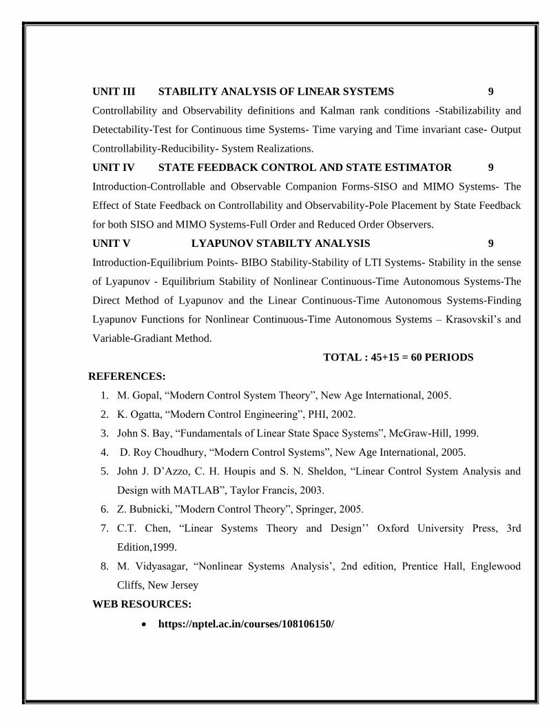
UNIT III STABILITY ANALYSIS OF LINEAR SYSTEMS 9
Controllability and Observability definitions and Kalman rank conditions -Stabilizability and
Detectability-Test for Continuous time Systems- Time varying and Time invariant case- Output
Controllability-Reducibility- System Realizations.
UNIT IV STATE FEEDBACK CONTROL AND STATE ESTIMATOR 9
Introduction-Controllable and Observable Companion Forms-SISO and MIMO Systems- The
Effect of State Feedback on Controllability and Observability-Pole Placement by State Feedback
for both SISO and MIMO Systems-Full Order and Reduced Order Observers.
UNIT V LYAPUNOV STABILTY ANALYSIS 9
Introduction-Equilibrium Points- BIBO Stability-Stability of LTI Systems- Stability in the sense
of Lyapunov - Equilibrium Stability of Nonlinear Continuous-Time Autonomous Systems-The
Direct Method of Lyapunov and the Linear Continuous-Time Autonomous Systems-Finding
Lyapunov Functions for Nonlinear Continuous-Time Autonomous Systems – Krasovskil’s and
Variable-Gradiant Method.
TOTAL : 45+15 = 60 PERIODS
REFERENCES:
1. M. Gopal, “Modern Control System Theory”, New Age International, 2005.
2. K. Ogatta, “Modern Control Engineering”, PHI, 2002.
3. John S. Bay, “Fundamentals of Linear State Space Systems”, McGraw-Hill, 1999.
4. D. Roy Choudhury, “Modern Control Systems”, New Age International, 2005.
5. John J. D’Azzo, C. H. Houpis and S. N. Sheldon, “Linear Control System Analysis and
Design with MATLAB”, Taylor Francis, 2003.
6. Z. Bubnicki, ”Modern Control Theory”, Springer, 2005.
7. C.T. Chen, “Linear Systems Theory and Design’’ Oxford University Press, 3rd
Edition,1999.
8. M. Vidyasagar, “Nonlinear Systems Analysis’, 2nd edition, Prentice Hall, Englewood
Cliffs, New Jersey
WEB RESOURCES:
• https://nptel.ac.in/courses/108106150/
Page 20
COURSE OUTCOMES:
CO105.1 Ability to represent the time-invariant systems in state space form as well as
analyze, whether the system is stabilizable, controllable, observable and
detectable.
CO105.2 Able to obtain the solutions to state equations.
CO105.3 Able to analyse the steady state stability of linear systems
CO105.4 Ability to design state feedback controller and state observers
CO105.5 Use the techniques such as describing function, Lyapunov Stability, Popov’s
Stability Criterion and Circle Criterion to assess the stability of certain class
of non-linear system.
POs Vs COs Mapping:
COs PO1 PO2 PO3 PO4 PO5 PO6 PO7 PO8 PO9 PO10
CO105.1 2 3 3 2 1 2
CO105.2 2 3 3 2 1 2
CO105.3 2 3 3 2 1 2
CO105.4 2 3 3 2 1 2
CO105.5 2 3 3 2 1 2
1→Low 2→Medium 3→High
19PS1611 POWER SYSTEM SIMULATION LABORATORY L T P C
0 0 4 2
OBJECTIVE(S):
• To have hands on experience on various system studies and different techniques
used for system planning using Software packages.
• To perform the dynamic analysis of power system.
Page 21
PRE REQUISTE:
• Power System Analysis
LIST OF EXPERIMENTS
1. Power flow analysis by Newton-Raphson method and Fast decoupled method
2. Transient stability analysis of single machine-infinite bus system using classical machine
model.
3. Contingency analysis: Generator shift factors and line outage distribution factors.
4. Economic dispatch using lambda-iteration method.
5. Unit commitment: Priority-list schemes and dynamic programming.
6. State Estimation (DC)
7. Analysis of switching surge using EMTP: Energization of a long distributed- parameter
line.
8. Analysis of switching surge using EMTP: Computation of transient recovery voltage.
9. Simulation and Implementation of Voltage Source Inverter.
10. Digital Over Current Relay Setting and Relay Coordination using Suitable software
packages.
11. Co-ordination of over-current and distance relays for radial line protection.
COURSE OUTCOME(S):
UponCompletionof thecourse, thestudentswill beableto: CO107.1 Analyze thepower flowusingNewton-Raphson method. CO107.2 Analyze thepower flow Fast decoupled method CO107.3 Perform contingencyanalysis&economicdispatch. C0107.4 SetDigital Over Current Relay C0107.5 Set CoordinateRelay
POs Vs COs Mapping:
COs PO1 PO2 PO3 PO4 PO5 PO6 PO7 PO8 PO9 PO10
CO107.1 1 1 2
CO107.2 1 2 2 2
CO107.3 2 2 3
C0107.4 2 3 3
C0107.5 3 3 2
1→Low 2→Medium 3→High
Page 22
19PS2601 DIGITAL PROTECTION FOR POWER SYSTEM L T P C
3 0 0 3
COURSE OBJECTIVES:
• To illustrateconceptsof transformerprotection.
• Todescribeabout thevariousschemesofOver currentprotection.
• Toanalyzedistanceandcarrier protection.
• Tofamiliarize theconceptsof GeneratorprotectionandNumerical protection.
PRE REQUISTES
Power System Analysis
Power System Operation and Control
Protection and Switch Gear
UNITI OVER CURRENT&EARTH FAULTPROTECTION 9
Zonesofprotection– Primary andBackup protection– operatingprinciplesandRelay
Construction- Time– Currentcharacteristics-Currentsetting– Timesetting-Overcurrent
protectiveschemes–ConceptofCoordination- Protectionofparallel /ringfeeders- Reverse power
or directional relay –Polarisation Techniques – Cross Polarisation– Quadrature Connection -
Earthfault and phasefault protection - Combined Earthfault and phase fault protectionscheme-
Phase faultprotective-schemedirectionalearth faultrelay -Staticover currentrelays–Numerical
over–currentprotection;numerical coordinationexamplefora radial feeder.
UNITII TRANSFORMER &BUSBAR PROTECTION 9
Typesoftransformers–Typesoffaultsin transformers- TypesofDifferential Protection–High
Impedance–External faultwithoneCTsaturation–ActualbehaviorsofaprotectiveCT–Circuit
modelofa saturatedCT-Need forhighimpedance–Disadvantages -PercentageDifferential
BiasCharacteristics–Vector group&itsimpactondifferentialprotection-Inrushphenomenon–
ZeroSequence filtering–Highresistance GroundFaultsin Transformers–RestrictedEarth fault
Protection-Inter-turn faultsintransformers–Incipient faultsintransformers-Phenomenon of
overfluxingintransformers– Transformerprotectionapplicationchart.Differentialprotectionof
busbarsexternalandinternal fault-Supervisory relay-protectionofthree–Phasebusbars–
Numerical examplesondesignofhighimpedancebusbardifferential scheme–BiasedDifferential
Page 23
Characteristics– ComparisonbetweenTransformerdifferential &Busbardifferential.
UNITIII DISTANCEAND CARRIER PROTECTION OFTRANSMISSION LINES
9
Drawbackofover–Currentprotection–Introductiontodistancerelay–Simpleimpedancerelay–
Reactancerelay–mhorelayscomparisonofdistancerelay–Distance protectionofathree– Phaseline-
reasonsforinaccuracy ofdistancerelayreach-Threesteppeddistanceprotection-
Tripcontactconfigurationforthethree-Steppeddistanceprotection-Three-steppedprotection
ofthree-phaselineagainstalltenshuntfaults-Impedanceseen fromrelayside-Three-stepped
protectionofdoubleendfedlines-needforcarrier–Aidedprotection–Variousoptionsfora carrier–
Couplingandtrappingthe carrierinto thedesiredlinesection-Unittypecarrieraided
directionalcomparisonrelaying–Carrieraideddistanceschemes foraccelerationofzoneΙΙ;
numerical examplefor atypical distanceprotectionschemefor atransmissionline.
UNITIV GENERATOR PROTECTION 9
Electricalcircuitofthe generator–Various faultsandabnormaloperatingconditions–Stator
WindingFaults–ProtectionagainstStator(earth)faults–thirdharmonicvoltageprotection– Rotor
fault–Abnormaloperatingconditions-ProtectionagainstRotor faults–Potentiometer Method –
injection method – Pole slipping– Loss ofexcitation– Protection againstMechanical faults;
Numerical examplesfor typical generatorprotectionschemes
UNITV NUMERICALPROTECTION 9
Introduction–Blockdiagramofnumerical relay-Samplingtheorem-Correlationwithareference
wave–Leasterrorsquared(LES) technique -Digital filtering-numerical over-Currentprotection–
Numerical transformer differential Protection-Numerical distanceprotectionoftransmission
line.
TOTAL:45 PERIODS
REFERENCES
1. Y.G.PaithankarandS.RBhide, “FundamentalsofPowerSystem Protection”, Prentice-Hall
ofIndia,2003.
2. Badri Ram andD.N.Vishwakarma, “PowerSystemProtectionandSwitchgear”,
TataMcGraw-Hill PublishingCompany,2002.
3. T.S.M.Rao, “Digital Relay/Numerical relays”,TataMcGrawHill,NewDelhi,1989.
4. P.Kundur, “PowerSystemStabilityandControl”, McGraw-Hill,1993.
Page 24
WEB RESOURCES
1. https://nptel.ac.in/courses/108101039/
2. http://www.cdeep.iitb.ac.in/webpage_data/nptel/Electrical%20Engineering/Power%20Sy
stem%20Protection/TOC_M1.html
COURSE OUTCOMES:
CO201.1 Learnerswill beable tounderstandthevariousschemesavailableinTransformer
protection.
CO201.2 Learnerswill haveknowledgeonOver current protection.
CO201.3 Learnerswill attainknowledgeaboutDistanceandCarrier
protectionintransmissionlines
CO201.4 Learnerswill understandtheconceptsof Generatorprotection.
CO201.5 Learnerswill attainbasicknowledgeonsubstationautomation.
POs Vs COs Mapping:
COs PO1 PO2 PO3 PO4 PO5 PO6 PO7 PO8 PO9 PO10
CO201.1 2 3
CO201.2 2 3
CO201.3 2 3
CO201.4 2 3
CO201.5 2 3 3 3
1→Low 2→Medium 3→High
19PS2602 POWER SYSTEM DYNAMICS AND STABILITY L T P C
3 0 0 3
OBJECTIVES:
• To impart knowledgeondynamicmodelingofasynchronous machine indetail.
• Todescribethemodelingofexcitationandspeedgoverningsystem indetail.
• Tounderstandthefundamentalconceptsofstabilityofdynamicsystemsandits
Page 25
classification.
• Tounderstandandenhancesmall signalstabilityproblemofpowersystems.
PRE-REQISITE:
• Transmission and distribution
• Power system operation and control
UNITI SYNCHRONOUSMACHINEMODELLING 9
SchematicDiagram,PhysicalDescription:armatureand fieldstructure, machineswithmultiple
polepairs,mmfwaveforms,directand quadratureaxes,MathematicalDescriptionofa
SynchronousMachine:Basicequationsofasynchronousmachine:statorcircuitequations,
statorself,statormutual andstatorto rotormutualinductances,dq0Transformation: fluxlinkage
andvoltageequations forstatorandrotorin dq0coordinates,electricalpowerandtorque,
physicalinterpretationofdq0transformation,Per UnitRepresentations:powerinvariantform of
Park‟stransformation;EquivalentCircuitsfordirectandquadratureaxes,Steady-stateAnalysis:
Voltage,currentand flux-linkagerelationships,Phasorrepresentation,Rotorangle,Steady-state
equivalentcircuit,Computationofsteady-state values,Equations ofMotion:SwingEquation,
calculationofinertiaconstant,Representation in systemstudies,SynchronousMachine
RepresentationinStability Studies:Simplifications forlarge-scalestudies:Neglectofstator
transients,Simplified modelwithamortisseurs neglected: two-
axismodelwithamortisseurwindingsneglected,classical model.
UNITII MODELLING OFEXCITATIONAND SPEED GOVERNING SYSTEMS 9
Excitation SystemRequirements; Elementsof an Excitation System; Types of Excitation
System;Controlandprotectivefunctions;IEEE(1992)blockdiagram forsimulationofexcitation
systems. TurbineandGoverningSystemModeling:FunctionalBlockDiagramofPower
GenerationandControl,Schematicofahydroelectricplant,classicaltransfer functionofa
hydraulicturbine(noderivation),specialcharacteristicofhydraulicturbine, electricalanalogueof
hydraulicturbine,GovernorforHydraulic Turbine:Requirementfora transientdroop,Block
diagramofgovernor with transientdroop compensation,Steam turbine modeling:Single reheat
tandemcompounded typeonlyand IEEEblockdiagram fordynamicsimulation; genericspeed-
governingsystem modelfor normal speed/loadcontrolfunction.
Page 26
UNITIII SMALL-SIGNALSTABILITYANALYSIS WITHOUT CONTROLLERS 9
Classification ofStability,Basic Concepts andDefinitions:Rotorangle stability, The Stability
Phenomena.Fundamental ConceptsofStabilityofDynamicSystems:State-space
representation,stability ofdynamic system,Linearization,Eigen properties of the state matrix:
Eigenvaluesandeigenvectors, modal matrices,Eigenvalueandstability,modeshapeand
participation factor.Single-MachineInfiniteBus(SMIB)Configuration:ClassicalMachineModel
stability analysiswithnumericalexample,EffectsofFieldCircuitDynamics:synchronous
machine,networkand linearisedsystemequations,blockdiagramrepresentationwithK-
constants;expression forK-constants(noderivation),effectof field fluxvariationonsystem
stability:analysiswithnumerical example.
UNITIVSMALL-SIGNALSTABILITYANALYSIS WITH CONTROLLERS
9
Effects OfExcitationSystem:EquationswithdefinitionsofappropriateK-constantsandsimple
thyristorexcitationsystemandAVR,blockdiagramwiththeexcitationsystem,analysisofeffect
ofAVR onsynchronizinganddampingcomponentsusinganumerical example,Power System
Stabilizer:Blockdiagramwith AVR and PSS,Illustration ofprinciple ofPSS application with
numericalexample,BlockdiagramofPSSwith description,systemstate matrix includingPSS,
analysisofstability withnumericalaexample.Multi-MachineConfiguration:Equationsina common
reference frame,equationsinindividual machinerotorcoordinates,illustrationof
formationofsystemstate matrixfora two-machinesystemwithclassicalmodelsforsynchronous
machines,illustrationofstability analysisusinganumericalexample.Principlebehindsmall- signal
stability improvement methods: delta-omegaanddelta P-omegastabilizers.
UNITV ENHANCEMENTOFSMALLSIGNALSTABILITY 9
PowerSystemStabilizer–Stabilizerbasedonshaftspeedsignal (deltaomega)–Delta–P- Omega
stabilizer-Frequency-basedstabilizers– DigitalStabilizer–Excitationcontroldesign– Exciter
gain–Phaseleadcompensation–Stabilizingsignal washoutstabilizer gain–Stabilizer limits
TOTAL: 45 PERIODS
TEXT BOOKS:
1. Mohan Mathur, R., Rajiv. K. Varma, “Thyristor – Based Facts Controllers for Electrical
Page 27
Transmission Systems”, IEEE press and John Wiley & Sons, Inc.
2. P. W. Sauer and M. A. Pai, “Power System Dynamics and Stability”, Stipes Publishing
Co, 2007.
3. P. Kundur, “Power System Stability and Control”, McGraw-Hill, 1993.
4. P.M Anderson and A.A Fouad, “Power System Control and Stability”, Iowa State
University Press, Ames, Iowa, 1978.
5. R.Ramunujam, “Power System Dynamics Analysis and Simulation”, PHI Learning
Private Limited, New Delhi, 2009.
WEB SOURCE(S):
• https://www.researchgate.net/publication/41231911_Power_System_Dynamics_St
ability_and_Control
COURSE OUTCOMES:
CO202.1 Learnerswill beable tounderstandondynamic
modellingofsynchronousmachine.
CO202.2 Learnerswill beable
tounderstandthemodelingofexcitationandspeedgoverning system for
stabilityanalysis.
CO202.3 Learnerswill attainknowledgeabout stabilityofdynamicsystems.
CO202.4 Learnerswill understandthesignificanceaboutsmall
signalstabilityanalysiswith controllers.
CO202.5 Learnerswill understandtheenhancement ofsmall signal stability.
POs Vs COs Mapping:
COs PO1 PO2 PO3 PO4 PO5 PO6 PO7 PO8 PO9 PO10
CO202.1 2 1 1 1 2
CO202.2 2 1 1 1 2
CO202.3 2 1 1 1 2
CO202.4 2 1 1 1 2
CO02.5 2 1 1 1 2
1→Low 2→Medium 3→High
Page 28
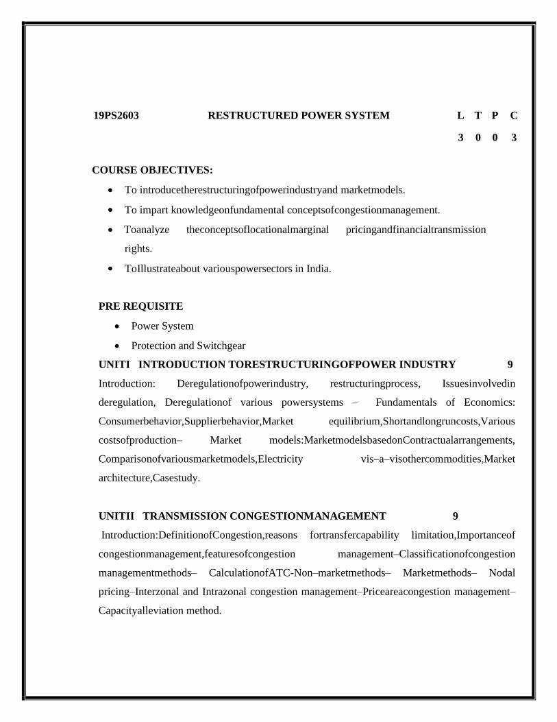
19PS2603 RESTRUCTURED POWER SYSTEM L T P C
3 0 0 3
COURSE OBJECTIVES:
• To introducetherestructuringofpowerindustryand marketmodels.
• To impart knowledgeonfundamental conceptsofcongestionmanagement.
• Toanalyze theconceptsoflocationalmarginal pricingandfinancialtransmission
rights.
• ToIllustrateabout variouspowersectors in India.
PRE REQUISITE
• Power System
• Protection and Switchgear
UNITI INTRODUCTION TORESTRUCTURINGOFPOWER INDUSTRY 9
Introduction: Deregulationofpowerindustry, restructuringprocess, Issuesinvolvedin
deregulation, Deregulationof various powersystems – Fundamentals of Economics:
Consumerbehavior,Supplierbehavior,Market equilibrium,Shortandlongruncosts,Various
costsofproduction– Market models:MarketmodelsbasedonContractualarrangements,
Comparisonofvariousmarketmodels,Electricity vis–a–visothercommodities,Market
architecture,Casestudy.
UNITII TRANSMISSION CONGESTIONMANAGEMENT 9
Introduction:DefinitionofCongestion,reasons fortransfercapability limitation,Importanceof
congestionmanagement,featuresofcongestion management–Classificationofcongestion
managementmethods– CalculationofATC-Non–marketmethods– Marketmethods– Nodal
pricing–Interzonal and Intrazonal congestion management–Priceareacongestion management–
Capacityalleviation method.
Page 29
UNITIII LOCATIONALMARGINALPRICESAND FINANCIAL
TRANSMISSIONRIGHTS
9
Mathematical preliminaries:-Locational marginal pricing–LosslessDCOPF model forLMP
calculation–LosscompensatedDCOPF model forLMPcalculation–ACOPFmodel forLMP
calculation–FinancialTransmissionrights – Riskhedging functionality -Simultaneous
feasibilitytestandrevenueadequency–FTRissuanceprocess:FTRauction,FTRallocation
–Treatmentofrevenueshortfall–Secondary tradingofFTRs–Flow gaterights–FTRand
marketpower -FTRandmerchant transmissioninvestment.
UNITIV ANCILLARYSERVICEMANAGEMENTANDPRICING OF
TRANSMISSIONNETWORK 9
Introductionofancillary services– TypesofAncillary services–ClassificationofAncillary
services–Loadgenerationbalancingrelatedservices –Voltagecontrol and reactivepower
supportdevices–Blackstartcapability service-Howtoobtainancillaryservice–Co-
optimizationofenergyand reserveservices-Transmissionpricing–Principles–Classification –
Rolled in transmission pricing methods – Marginal transmission pricing paradigm –
Compositepricingparadigm–Meritsanddemeritsofdifferentparadigm.
UNITV REFORMSININDIANPOWER SECTOR 9
Introduction–FrameworkofIndianpowersector–Reforminitiatives-Availabilitybasedtariff –
Electricityact2003 – Openaccess issues–Powerexchange–Reforms in thenearfuture.
TOTAL: 45 PERIODS
REFERENCES:
1. MohammadShahidehpour, MuwaffaqAlomoush, Marcel Dekker, “Restructured electrical
powersystems:operation, tradingandvolatility”Pub.,2001.
2. KankarBhattacharya,JaapE.Daadler,MathH.J. Boolen, “Operationofrestructured
powersystems”,Kluwer AcademicPub., 2001.
3. Paranjothi,S.R., “ModernPowerSystems”Paranjothi, S.R.,NewAgeInternational,2017.
Page 30
4. Sally Hunt,” Makingcompetitionworkinelectricity”,JohnWilleyandSons Inc.2002.
5. Steven Stoft, “Power system economics: designing markets for electricity”, John
Wiley & Sons, 2002.
WEB RESOURCES:
1. https://nptel.ac.in/courses/108101005/
2. https://nptel.ac.in/content/storage2/courses/108101040/download/Lec-33.pdf
3. https://www.coursebuffet.com/course/829/nptel/restructured-power-systems-iit-bombay
COURSE OUTCOMES:
CO203.1 Learners will have knowledge on restructuring of power industry
CO203.2 Learners will understand basics of congestion management
CO203.3 Learners will attain knowledge about locational margin prices and financial
transmission rights
CO203.4 Learners will understand the significance ancillary services and pricing of
transmission network
CO203.5 Learners will have knowledge on the various power sectors in India.
POs Vs COs Mapping:
COs PO1 PO2 PO3 PO4 PO5 PO6 PO7 PO8 PO9 PO10
1 3 2 2
2 3 2 2
3 3 2 2 2
4 3 2 2
5 3 2 2
1→Low 2→Medium 3→High
Page 31
19PE2705 FLEXIBLE AC TRANSMISSION SYSTEMS L T P C
3 0 0 3
OBJECTIVES:
• To emphasis the need for FACTS controllers.
• To learn the characteristics, applications and modelling of series and shunt FACTS
controllers.
• To analyze the interaction of different FACTS controller and perform control
coordination.
PRE-REQISITE:
• High Voltage Direct Current Engineering
• High Voltage Engineering
UNIT I INTRODUCTION 9
Review of basics of power transmission networks-control of power flow in AC transmission
line Analysis of uncompensated AC Transmission line- Passive reactive power
compensation: Effect of series and shunt compensation at the mid-point of the line on power
transfer- Need for FACTS controllers- types of FACTS controllers.
UNIT II STATIC VAR COMPENSATOR (SVC) 9
Configuration of SVC- voltage regulation by SVC- Modelling of SVC for load flow
analysis Modelling of SVC for stability studies-Design of SVC to regulate the mid-point
voltage ofa SMIB system- Applications: transient stability enhancement and power
oscillation damping of SMIB system with SVC connected at the mid-point of the line.
UNIT III THYRISTOR AND GTO THYRISTOR CONTROLLED SERIES
CAPACITORS (TCSC and GCSC) 9
Concepts of Controlled Series Compensation – Operation of TCSC and GCSC- Analysis
ofTCSC-GCSC – Modelling of TCSC and GCSC for load flow studies- modelling TCSC and
GCSC for stability studied- Applications of TCSC and GCSC.
UNIT IV VOLTAGE SOURCE CONVERTER BASED FACTS CONTROLLERS 9
Static synchronous compensator(STATCOM)- Static synchronous series
Page 32
compensator(SSSC)-Operation of STATCOM and SSSC-Power flow control with
STATCOM and SSSC- Modelling of STATCOM and SSSC for power flow and transient
stability studies –operation of Unified and Interline power flow controllers(UPFC and IPFC)-
Modelling of UPFC and IPFC for load flow and transient stability studies- Applications.
UNIT V CONTROLLERS AND THEIR COORDINATION 9
FACTS Controller interactions – SVC–SVC interaction - co-ordination of multiple
controllers using linear control techniques – Quantitative treatment of control coordination.
TOTAL : 45 PERIODS
REFERENCES:
1. A.T.John, “Flexible AC Transmission System”, Institution of Electrical and Electronic
Engineers (IEEE), 1999.
2. NarainG.Hingorani, Laszio. Gyugyl, “Understanding FACTS Concepts and Technology
of Flexible AC Transmission System”, Standard Publishers, Delhi 2001.
3. V. K.Sood, “HVDC and FACTS controllers- Applications of Static Converters in Power
System”, 2004, Kluwer Academic Publishers.
4. Mohan Mathur, R., Rajiv. K. Varma, “Thyristor – Based Facts Controllers for Electrical
Transmission Systems”, IEEE press and John Wiley & Sons, Inc.
5. K.R.Padiyar,” FACTS Controllers in Power Transmission and Distribution”, New Age
International(P) Ltd., Publishers New Delhi, Reprint 2008.
WEB SOURCES:
• https://www.electrical4u.com/facts-on-facts-theory-and-applications/
• https://www.gegridsolutions.com/facts.htm
COURSE OUTCOMES:
CO204.1 Ability to understand the operation of the ac transmission lines and various
types of FACTS
CO204.2 Ability to understand the basic concepts of VAR compensators
CO204.3 Ability to know about the modeling and applications of thyistors and GTO
CO204.4 Ability to understand the basic concepts voltage source convertor based
FACTS
Page 33
CO204.5 Ability to analysis the various Controllers and their Coordination
POs Vs COs Mapping:
Cos PO1 PO2 PO3 PO4 PO5 PO6 PO7 PO8 PO9 PO10
CO204.1 2 2 1 2 2
CO204.2 2 2 1 2 2
CO204.3 2 2 1 2 2
CO204.4 2 2 1 2 2
CO204.5 2 2 1 2 2
1→Low 2→Medium 3→High
19PS2611 ADVANCED POWER SYSTEMSIMULATION
LABORATORY L T P C
0 0 4 2
OBJECTIVES
• ToIntroduce the infinite bus system for single and classical machines.
• Toimpart knowledge on starting characteristics of AC machines using hands on
training.
• To compute the two-bus system with STATCOM
• To design the variable speed wind energy conversion system
• To design the various active filters for improving the power quality
PRE-REQUISITE:
• Power system Analysis
• Power System operation control
• Power Quality
LISTOFEXPERIMENTS
1. Small-signal stabilityanalysisofsinglemachine-infinitebussystem usingclassical
machinemodel
2. Small-signal stabilityanalysisofmulti-machineconfigurationwithclassicalmachinemodel
Page 34
3. Inductionmotor startinganalysis.
4. Loadflowanalysisoftwo-bussystemwithSTATCOM.
5. Transientanalysisoftwo-bussystemwithSTATCOM.
6. AvailableTransfer Capabilitycalculationusinganexistingloadflowprogram.
7. Studyofvariablespeed windenergyconversionsystem- DFIG.
8. Studyofvariablespeed windenergyconversionsystem- PMSG.
9. ComputationofharmonicindicesgeneratedbyarectifierfeedingaR-Lload.
10. Designofactivefilterfor mitigatingharmonics.
TOTAL:30 PERIODS
WEB SOURCE(S):
• https://nptel.ac.in/courses/108105067/
COURSE OUTCOMES(S):
UponCompletionof thecourse, thestudentswill beableto:
CO207.1 Ability to analysisofsinglemachine-infinitebussystem usingclassical
machinemodel
CO207.2 Ability to analysisof starting of AC Machine
CO207.3 Ability to analysisoftwo-bussystemwithSTATCOM
CO207.4 Understand the concept of variablespeed windenergyconversionsystem
CO207.5 Ability to design the active filter for filtering harmonics
PO vs CO Mapping
CO No PO1 PO2 PO3 PO4 PO5 PO6 PO7 PO8 PO9 PO10
CO207.1 3 2 2 2 2 2
CO207.2 3 2 2 2 2 2
CO207.3 3 2 2 1 2 2 2
CO207.4 3 2 2 1 2 2 2
CO207.5 3 2 2 2 2 2 2
1→Low 2→Medium 3→High
Page 35
19PE1603 MODELLING AND ANALYSIS OF
ELECTRICAL MACHINES
L T P C
3 0 0 3
OBJECTIVES:
• To provide knowledge about the fundamentals of magnetic circuits, energy, force and
torque of multi-excited systems.
• To analyze the steady state and dynamic state operation of DC machine through
mathematical modeling and simulation in digital computer.
• To provide the knowledge of theory of transformation of three phase variables to two
phase variables.
• To analyze the steady state and dynamic state operation of three-phase induction machines
using transformation theory based mathematical modeling and digital computer
simulation.
• To analyze the steady state and dynamic state operation of three-phase synchronous
machines using transformation theory based mathematical modeling and digital computer
simulation.
PRE-REQUISITE:
• Electrical Machines
UNIT I PRINCIPLES OF ELECTROMAGNETIC ENERGY CONVERSION 9
Magnetic circuits, permanent magnet, stored magnetic energy, co-energy - force and torque in
singly and doubly excited systems – machine windings and air gap mmf - winding inductances
and voltage equations.
UNIT II DC MACHINES 9
Elementary DC machine and analysis of steady state operation - Voltage and torque equations –
dynamic characteristics of permanent magnet and shunt d.c. motors – Time domain block
diagrams - solution of dynamic characteristic by Laplace transformation – digital computer
simulation of permanent magnet and shunt D.C. machines.
Page 36
UNIT III REFERENCE FRAME THEORY 9
Historical background – phase transformation and commutator transformation – transformation
of variables from stationary to arbitrary reference frame - variables observed from several frames
of reference.
UNIT IV INDUCTION MACHINES 9
Three phase induction machine, equivalent circuit and analysis of steady state operation – free
acceleration characteristics – voltage and torque equations in machine variables and arbitrary
reference frame variables – analysis of dynamic performance for load torque variations – digital
computer simulation.
UNIT V SYNCHRONOUS MACHINES 9
Three phase synchronous machine and analysis of steady state operation - voltage and torque
equations in machine variables and rotor reference frame variables (Park’s equations) –analysis
of dynamic performance for load torque variations – Generalized theory of rotating electrical
machine.
TOTAL: 45 PERIODS
REFERENCE BOOKS:
1. Paul C.Krause, Oleg Wasyzczuk, Scott S, Sudhoff, “Analysis of Electric Machinery and
Drive Systems”, John Wiley, Second Edition, 2010.
2. P S Bimbhra, “Generalized Theory of Electrical Machines”, Khanna Publishers, 2008.
3. A.E, Fitzgerald, Charles Kingsley, Jr, and Stephan D, Umanx, “Electric Machinery”, Tata
McGraw Hill, 5th Edition, 1992.
4. R. Krishnan, Electric Motor & Drives: Modeling, Analysis and Control, New Delhi,
Prentice Hall of India, 2001.
WEB SOURCES:
1. https://nptel.ac.in/content/syllabus_pdf/108106023.pdf
2. https://nptel.ac.in/courses/108106023/
Page 37
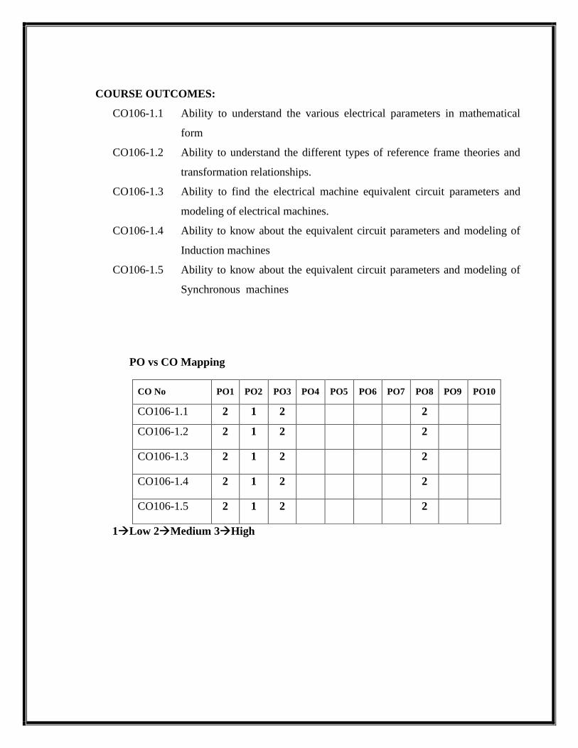
COURSE OUTCOMES:
CO106-1.1 Ability to understand the various electrical parameters in mathematical
form
CO106-1.2 Ability to understand the different types of reference frame theories and
transformation relationships.
CO106-1.3 Ability to find the electrical machine equivalent circuit parameters and
modeling of electrical machines.
CO106-1.4 Ability to know about the equivalent circuit parameters and modeling of
Induction machines
CO106-1.5 Ability to know about the equivalent circuit parameters and modeling of
Synchronous machines
PO vs CO Mapping
CO No PO1 PO2 PO3 PO4 PO5 PO6 PO7 PO8 PO9 PO10
CO106-1.1 2 1 2 2
CO106-1.2 2 1 2 2
CO106-1.3 2 1 2 2
CO106-1.4 2 1 2 2
CO106-1.5 2 1 2 2
1→Low 2→Medium 3→High
Page 38
19PE1604 SOLAR AND ENERGY STORAGE SYSTEMS L T P C
3 0 0 3
COURSE OBJECTIVES:
• To Study about solar modules and PV system design and their applications
• To Deal with grid connected PV systems
• To Discuss about different energy storage systems
PRE-REQISITE:
Power Electronics for Renewable Energy Systems
UNIT I INTRODUCTION 9
Characteristics of sunlight – semiconductors and P-N junctions –behavior of solar cells – cell
properties – PV cell interconnection
UNIT II STAND ALONE PV SYSTEM 9
Solar modules – storage systems – power conditioning and regulation - MPPT- protection –stand
alone PV systems design – sizing
UNIT III GRID CONNECTED PV SYSTEMS 9
PV systems in buildings – design issues for central power stations – safety – Economic aspect –
Efficiency and performance - International PV programs
UNIT IV ENERGY STORAGE SYSTEMS 9
Impact of intermittent generation – Battery energy storage – solar thermal energy storage –
pumped hydroelectric energy storage
UNIT V APPLICATIONS 9
Water pumping – battery chargers – solar car – direct-drive applications –Space –
Telecommunications.
TOTAL : 45 PERIODS
REFERENCES
1. Solanki C.S., “Solar Photovoltaics: Fundamentals, Technologies And Applications”, PHI
Learning Pvt. Ltd.,2015.
2. Stuart R.Wenham, Martin A.Green, Muriel E. Watt and Richard Corkish,
“AppliedPhotovoltaics”, 2007,Earthscan, UK.
Page 39
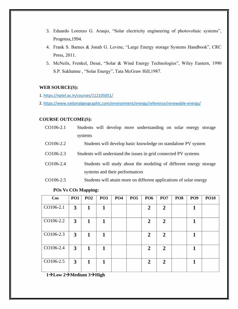
3. Eduardo Lorenzo G. Araujo, “Solar electricity engineering of photovoltaic systems”,
Progensa,1994.
4. Frank S. Barnes & Jonah G. Levine, “Large Energy storage Systems Handbook”, CRC
Press, 2011.
5. McNeils, Frenkel, Desai, “Solar & Wind Energy Technologies”, Wiley Eastern, 1990
S.P. Sukhatme , “Solar Energy”, Tata McGraw Hill,1987.
WEB SOURCE(S):
1. https://nptel.ac.in/courses/112105051/
2. https://www.nationalgeographic.com/environment/energy/reference/renewable-energy/
COURSE OUTCOME(S):
CO106-2.1 Students will develop more understanding on solar energy storage
systems
CO106-2.2 Students will develop basic knowledge on standalone PV system
CO106-2.3 Students will understand the issues in grid connected PV systems
CO106-2.4 Students will study about the modeling of different energy storage
systems and their performances
CO106-2.5 Students will attain more on different applications of solar energy
POs Vs COs Mapping:
Cos PO1 PO2 PO3 PO4 PO5 PO6 PO7 PO8 PO9 PO10
CO106-2.1 3 1 1 2 2 1
CO106-2.2 3 1 1 2 2 1
CO106-2.3 3 1 1 2 2 1
CO106-2.4 3 1 1 2 2 1
CO106-2.5 3 1 1 2 2 1
1→Low 2→Medium 3→High
Page 40
19PE2704 SOFT COMPUTING TECHNIQUES L T P C
3 0 0 3
OBJECTIVES:
• To expose the concepts of feed forward neural networks.
• To provide adequate knowledge about feedback neural networks.
• To teach about the concept of fuzziness involved in various systems.
• To expose the ideas about genetic algorithm
• To provide adequate knowledge about of FLC and NN toolbox
PRE-REQUISITE:
• Engineering Physics
UNIT I INTRODUCTION AND ARTIFICIAL NEURAL NETWORKS 9
Introduction to intelligent systems- Soft computing techniques- Conventional Computing versus
Swarm Computing - Classification of meta-heuristic techniques - Properties of Swarm
Intelligent Systems - Application domain - Discrete and continuous problems - Single
objective and multi-objective problems -Neuron- Nerve structure and synapse- Artificial
Neuron and its model- activation functions- Neural network architecture- single layer and
multilayer feed forward networks- Mc Culloch Pitts neuron model- perceptron model-
Adaline and Madaline- multilayer perception model- back propagation learning methods- effect
of learning rule coefficient -back propagation algorithm- factors affecting back propagation
training- applications.
UNIT II ARTIFICIAL NEURAL NETWORKS AND ASSOCIATIVE MEMORY 9
Counter propagation network- architecture- functioning & characteristics of counter Propagation
network- Hopfield/ Recurrent network configuration - stability constraints associative memory
and characteristics- limitations and applications- Hopfield v/s Boltzman machine- Adaptive
Page 41
Resonance Theory- Architecture- classifications- Implementation and training - Associative
Memory.
UNIT III FUZZY LOGIC SYSTEM 9
Introduction to crisp sets and fuzzy sets- basic fuzzy set operation and approximate reasoning.
Introduction to fuzzy logic modeling and control- Fuzzification inferencing and defuzzification-
Fuzzy knowledge and rule bases-Fuzzy modeling and control schemes for nonlinear systems.
Self-organizing fuzzy logic control- Fuzzy logic control for nonlinear time delay system.
UNIT IV GENETIC ALGORITHM 9
Evolutionary programs – Genetic algorithms, genetic programming and evolutionary
programming - Genetic Algorithm versus Conventional Optimization Techniques - Genetic
representations and selection mechanisms; Genetic operators- different types of crossover and
mutation operators - Optimization problems using GA-discrete and continuous - Single objective
and multi-objective problems - Procedures in evolutionary programming.
UNIT V HYBRID CONTROL SCHEMES 9
Fuzzification and rule base using ANN–Neuro fuzzy systems-ANFIS – Fuzzy Neuron -
Optimization of membership function and rule base using Genetic Algorithm –Introduction to
Support Vector Machine- Evolutionary Programming-Particle Swarm Optimization - Case study
– Familiarization of NN, FLC and ANFIS Tool Box.
TOTAL: 45 PERIODS
TEXT BOOKS:
1. Laurene V. Fausett, “Fundamentals of Neural Networks: Architectures, Algorithms And
Applications”, Pearson Education.
2. Timothy J. Ross, “Fuzzy Logic with Engineering Applications” Wiley India, 2008.
3. Zimmermann H.J. "Fuzzy set theory and its Applications" Springer international edition,
2011.
4. David E.Goldberg, “Genetic Algorithms in Search, Optimization, and Machine
Learning”, Pearson Education, 2009.
5. W.T.Miller, R.S.Sutton and P.J.Webrose, “Neural Networks for Control” MIT Press”,
1996.
6. T. Ross, “Fuzzy Logic with Engineering Applications”, Tata McGraw Hill, New Delhi,
1995.
Page 42
7. EthemAlpaydin, “Introduction to Machine Learning (Adaptive Computation and
Machine Learning Series)”, MIT Press, 2004.
8. Corinna Cortes and V. Vapnik, " Support - Vector Networks, Machine Learning ” 1995.
WEB SOURCES:
3. https://nptel.ac.in/courses/106/105/106105173/
4. https://nptel.ac.in/content/storage2/nptel_data3/html/mhrd/ict/text/106105173/lec1.pdf
COURSE OUTCOMES:
CO106-3.1 Will be able to know the basic ANN architectures, algorithms and their
limitations.
CO106-3.2 Will be able to know the different operations on the fuzzy sets.
CO106-3.3 Will be capable of developing ANN based models and control schemes for
non-linear system.
CO106-3.4 Will get expertise in the use of different ANN structures and online
training algorithm.
CO106-3.5 Will be knowledgeable to use Fuzzy logic for modeling and control of
non-linear systems.
PO vs CO Mapping
CO No PO1 PO2 PO3 PO4 PO5 PO6 PO7 PO8 PO9 PO10
CO106-3.1 1 2 2 1
CO106-3.2 1 2 2 1
CO106-3.3 1 2 2 1
CO106-3.4 1 2 2 1
CO106-3.5 1 2 2 1
1→Low 2→Medium 3→High
Page 43
19PE3707 SMART GRID L T P C
3 0 0 3
OBJECTIVES:
• To Study about Smart Grid technologies, different smart meters and advanced metering
infrastructure.
• To familiarize the power quality management issues in Smart Grid.
• To familiarize the high performance computing for Smart Grid applications.
PRE -REQUISITE:
• Transmission & Distribution
• Power System Analysis
UNIT I INTRODUCTION TO SMART GRID 9
Evolution of Electric Grid, Concept, Definitions and Need for Smart Grid, Smart grid drivers,
functions, opportunities, challenges and benefits, Difference between conventional & Smart
Grid, National and International Initiatives in Smart Grid.
UNIT II SMART GRID TECHNOLOGIES 9
Technology Drivers, Smart energy resources, Smart substations, Substation Automation,
Feeder Automation ,Transmission systems: EMS, FACTS and HVDC, Wide area monitoring,
Protection and control, Distribution systems: DMS, Volt/Var control, Fault Detection, Isolation
and service restoration, Outage management, High-Efficiency Distribution Transformers, Phase
Shifting Transformers, Plug in Hybrid Electric Vehicles (PHEV).
UNIT III SMART METERS AND ADVANCED METERING INFRASTRUCTURE
9
Introduction to Smart Meters, Advanced Metering infrastructure (AMI) drivers and benefits,
AMI protocols, standards and initiatives, AMI needs in the smart grid, Phasor Measurement
Page 44
Unit(PMU), Intelligent Electronic Devices (IED) & their application for monitoring &
protection.
UNIT IV POWER QUALITY MANAGEMENT IN SMART GRID 9
Power Quality & EMC in Smart Grid, Power Quality issues of Grid connected Renewable
Energy Sources, Power Quality Conditioners for Smart Grid, Web based Power Quality
monitoring, Power Quality Audit.
UNIT V HIGH PERFORMANCE COMPUTING FOR SMART
GRIDAPPLICATIONS 9
Local Area Network (LAN), House Area Network (HAN), Wide Area Network
(WAN),Broadband over Power line (BPL), IP based Protocols, Basics of Web Service and cloud
Computing to make Smart Grids smarter, Cyber Security for Smart Grid.
TOTAL : 45 PERIODS
REFERENCES:
1. Stuart Borlase “Smart Grid :Infrastructure, Technology and Solutions”, CRC Press 2012.
2. Janaka Ekanayake, Nick Jenkins, KithsiriLiyanage, Jianzhong Wu, Akihiko Yokoyama,
“Smart Grid: Technology and Applications”, Wiley 2012.
3. Vehbi C. Güngör, DilanSahin, TaskinKocak, Salih Ergüt, ConcettinaBuccella, Carlo
Cecati, and Gerhard P. Hancke, “Smart Grid Technologies: Communication
Technologies and Standards” IEEE Transactions On Industrial Informatics, Vol. 7, No. 4,
November 2011.
4. Xi Fang, SatyajayantMisra, Guoliang Xue, and Dejun Yang “Smart Grid – The
NewandImproved Power Grid: A Survey” , IEEE Transaction on Smart Grids, vol. 14,
2012.
WEB RESOURCES:
1. https://nptel.ac.in/courses/108/107/108107113/
2. http://www.digimat.in/nptel/courses/video/108107113/108107113.html
3. http://www.digimat.in/nptel/courses/video/108107113/108107113.html
Page 45
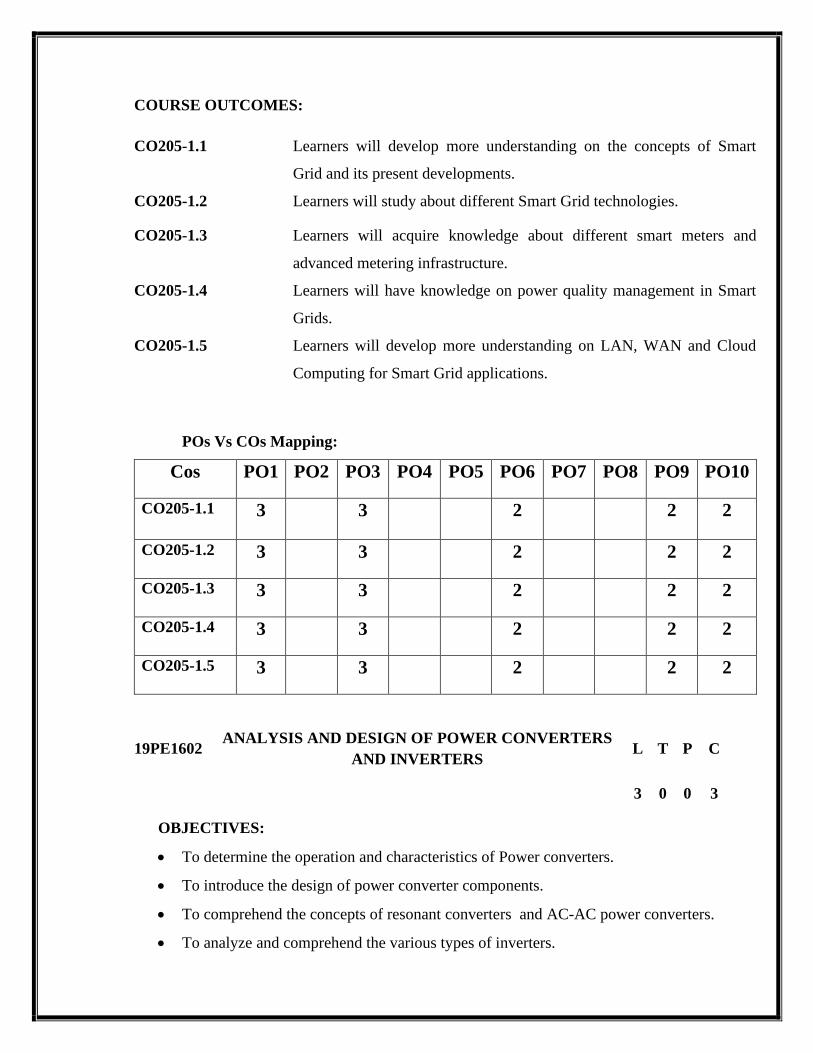
COURSE OUTCOMES:
CO205-1.1 Learners will develop more understanding on the concepts of Smart
Grid and its present developments.
CO205-1.2 Learners will study about different Smart Grid technologies.
CO205-1.3 Learners will acquire knowledge about different smart meters and
advanced metering infrastructure.
CO205-1.4 Learners will have knowledge on power quality management in Smart
Grids.
CO205-1.5 Learners will develop more understanding on LAN, WAN and Cloud
Computing for Smart Grid applications.
POs Vs COs Mapping:
Cos PO1 PO2 PO3 PO4 PO5 PO6 PO7 PO8 PO9 PO10
CO205-1.1 3 3 2 2 2
CO205-1.2 3 3 2 2 2
CO205-1.3 3 3 2 2 2
CO205-1.4 3 3 2 2 2
CO205-1.5 3 3 2 2 2
19PE1602 ANALYSIS AND DESIGN OF POWER CONVERTERS
AND INVERTERS L T P C
3 0 0 3
OBJECTIVES:
• To determine the operation and characteristics of Power converters.
• To introduce the design of power converter components.
• To comprehend the concepts of resonant converters and AC-AC power converters.
• To analyze and comprehend the various types of inverters.
Page 46
• To impart knowledge on multilevel inverters and Boost inverters.
PRE-REQUISITE:
• Power Electronics
• Solid State Drives
• Power Electronics For Renewable Energy Sources.
UNIT I POWER CONVERTERS 9
single-phase and Three phase full converter and semi converter (RL,RLE load)- Dual
converter – PWM rectifiers.Operation and analysis of Buck, Boost, Buck-Boost, Cuk&
SEPIC – under continuous and discontinuous operation – Isolated converters: basic
operation of Fly back, Forward and Push-pull topologies.
UNIT II DESIGN OF POWER CONVERTER COMPONENTS 9
Introduction to magnetic materials- hard and soft magnetic materials –types of cores ,
copper windings – Design of transformer –Inductor design equations –Examples of
inductor design for buck/flyback converter-selection of output filter capacitors – selection
of ratings for devices – input filter design.
UNIT III RESONANT DC-DC CONVERTERS& AC-AC CONVERTERS 9
Resonant switch converters – operation and analysis of ZVS, ZCS converters comparison
of ZCS/ZVS Introduction to ZVT/ZCT PWM converters.Single phase ac voltage
controller – analysis with R & RL load – Three phase ac voltage controller – principle of
operation of cyclo converter – single phase and three phase cyclo converters –
Introduction to matrix converters.
UNIT IV VOLTAGE SOURCE AND CURRENT SOURCE INVERTERS 9
Principle of operation of single phase full bridge inverters, Three phase Inverter: 180
degree and 120 degree conduction mode inverters – voltage control of inverters : Space
vector modulation techniques .Operation of six-step thyristor inverter load – commutated
inverters – Auto sequential current source inverter (ASCI), PWM techniques forcurrent
source inverters.
Page 47
UNIT V MULTILEVEL INVERTERS , BOOST & RESONANT
INVERTERS 9
Multilevel concept – diode clamped – flying capacitor – cascade type multilevel inverters
-Comparison of multilevel inverters .Series and parallel resonant inverters - voltage
control of resonant inverters – Class Eresonant inverter – resonant DC - link inverters
TOTAL : 45 PERIODS
TEXT BOOKS:
1. Ned Mohan,T.MUndeland and W.P Robbin, “Power Electronics: converters, Application
and design” John Wiley and sons.Wiley India edition, 2006.
2. Rashid M.H., “Power Electronics Circuits, Devices and Applications ", Prentice Hall
India, Third Edition, New Delhi, 2004.
3. P.C. Sen, “Modern Power Electronics”, Wheeler Publishing Co, First Edition, New
Delhi, 1998.
4. P.S.Bimbra, “Power Electronics”, Khanna Publishers, Eleventh Edition, 2003.
5. Simon Ang, Alejandro Oliva, “Power-Switching Converters, Second Edition, CRC Press,
Taylor & Francis Group, 2010.
6. V.Ramanarayanan, “Course material on Switched mode power conversion”, 2007.
REFERENCES:
1. Alex Van den Bossche and VencislavCekovValchev, “Inductors
andTransformersforPowerElectronics”, CRC Press, Taylor & Francis Group, 2005.
2. W. G. Hurley and W. H.Wolfle, “Transformers and Inductors for Power Electronics
Theory, Design and Applications”, 2013 John Wiley & Sons Ltd.
3. Marian.K.Kazimierczuk and DariuszCzarkowski, “Resonant Power Converters”, John
Wiley & Sons limited, 2011.
4. Jai P.Agrawal, “Power Electronics Systems”, Pearson Education, Second Edition,
2002
Page 48
5. Bimal K.Bose “Modern Power Electronics and AC Drives”, Pearson Education,
Second Edition, 2003.
6. Philip T. krein, “Elements of Power Electronics” Oxford University Press -1998.
WEB RESOURCES:
1. https://www.powerelectronics.com/technologies/dc-dc-
converters/article/21861281/buckconverter-design-demystified
2. https://www.youtube.com/watch?v=LwPJi3jyfw0
3. http://dese.iisc.ac.in/design-of-power-converters/
COURSE OUTCOMES:
CO205-2.1 Analyze various power converters
CO205-2.2 Develop improved power converters for any stringent application
requirements.
CO205-2.3 Design resonant and ac-ac converters.
CO205-2.4 Develop various types of inverter.
CO205-2.5 Design Multilevel Inverters and boot inverters.
POs Vs COs Mapping:
COs PO1 PO2 PO3 PO4 PO5 PO6 PO7 PO8 PO9 PO10
CO205-2.1 3 3 3
CO205-2.2 3 2 3
CO205-2.3 3 2 3
CO205-2.4 3 2 3
CO205-2.5 3 2 3
Page 49
19PS2701 POWER SYSTEMRELIABILITY L T P C
3 0 0 3
OBJECTIVES:
• To introducestheobjectivesofLoadforecasting.
• Tostudy thefundamentalsofGenerationsystem, transmissionsystemand Distribution
system reliabilityanalysis
• To understandtheContingencyanalysisandProbabilisticLoadflow Analysis.
• To illustratethebasicconceptsofExpansionplanning.
• To gain knowledgeonthefundamentalconceptsoftheDistributionsystem planning.
PRE-REQISITE:
• Transmission and Distribution
• Power System Analysis
• Protection and Switchgear
• Power Quality
UNITI LOAD FORECASTING 9
Objectivesofforecasting-Load growthpatternsandtheirimportance inplanning-Load
forecastingBased ondiscounted multiple regression technique-Weathersensitiveload
forecasting-Determinationofannualforecasting-UseofAIin loadforecasting.
UNITII GENERATION SYSTEMRELIABILITYANALYSIS 9
Probabilisticgeneration andloadmodels-DeterminationofLOLPandexpectedvalueof demand
not served –Determination of reliability of ISO and interconnected generation systems.
UNITIII TRANSMISSION SYSTEMRELIABILITYANALYSIS 9
Deterministiccontingencyanalysis-probabilisticloadflow-Fuzzyloadflow probabilistic
transmissionsystemreliability analysis-DeterminationofreliabilityindiceslikeLOLPand
expectedvalueofdemandnot served.
UNITIV EXPANSION PLANNING 9
Basicconceptsonexpansionplanning-procedurefollowedforintegrate transmissionsystem
planning,currentpractice in India-Capacitorplacerproblemin transmission systemand radial
distributionssystem.
Page 50
UNITV DISTRIBUTION SYSTEMPLANNING OVERVIEW 9
Introduction, sub transmission lines and distribution substations-Design primary and
secondarysystems-distributionsystem protectionandcoordinationofprotectivedevices.
TOTAL: 45 PERIODS
REFERENCES
1. Frank S. Barnes & Jonah G. Levine, “Large Energy storage Systems Handbook”,
CRC Press, 2011.
2. McNeils, Frenkel, Desai, “Solar & Wind Energy Technologies”, Wiley Eastern, 1990
3. S.P. Sukhatme , “Solar Energy”, Tata McGraw Hill,1987.
4. RoyBillinton&RonaldN.Allan, “ReliabilityEvaluationofPowerSystems”Springer
Publication,
5. R.L.Sullivan,“PowerSystem Planning”,TataMcGrawHill PublishingCompanyLtd 1977.
6. X.Wang&J.R. McDonald, “ModernPowerSystemPlanning”, McGrawHill Book
Company1994.
7. T. Gonen, “Electrical PowerDistributionEngineering”, McGrawHill BookCompany 1986.
8. B.R. Gupta, “GenerationofElectrical Energy”,S.ChandPublications1983.
WEB RESOURCES:
• https://www.intechopen.com/books/system-reliability/power-system-reliability-
mathematical-models-and-applications
• https://www.sciencedirect.com/science/article/abs/pii/095183209090007A
• https://link.springer.com/chapter/10.1007/978-1-84996-232-2_8
• https://www.researchgate.net/publication/278683001_Electric_Power_System_Reliability
• https://www.energy.gov/sites/prod/files/2017/01/f34/Maintaining%20Reliability%20in%20
the%20Modern%20Power%20System.pdf
Page 51
COURSE OUTCOMES:
CO205
-3.1
Studentswill develop theabilitytolearnabout loadforecasting.
CO205
-3.2
Studentswill learnabout reliabilityanalysisofISOand interconnectedsystems.
CO205
-3.3
StudentswillunderstandtheconceptsofContingencyanalysisandProbabilisticLoadfl
ow Analysis.
CO205
-3.4
Studentswill beable tounderstandtheconceptsofExpansionplanning
CO205
-3.5
StudentswillhaveknowledgeonthefundamentalconceptsoftheDistributionsystem
planning.
POs Vs COs MAPPING:
CO No PO1 PO2 PO3 PO4 PO5 PO6 PO7 PO8 PO9 PO10
CO205-3.1 3 3 3
CO205-3.2 3
CO205-3.3 2 2 3 2
CO205-3.4 2 2
CO205-3.5 3 3
1→Low 2→Medium 3→High
19PE3701 HIGH VOLTAGE DIRECT CURRENTTRANSMISSION L T P C
3 0 0 3
OBJECTIVES:
• To impart knowledge on DC Power Transmission Technology
• To impart knowledge on operation, modelling and control of HVDC link.
• To impart knowledge on Multiterminal system
Page 52
• To perform steady state analysis of AC/DC system.
• To expose various HVDC simulators.
PRE-REQISITE:
• Power Electronics
• Power Generation Systems
• Power systems Analysis
• Power system operation and control
UNIT I DC POWER TRANSMISSION TECHNOLOGY 9
Introduction - Comparison of AC and DC transmission – Application of DC transmission –
Description of DC transmission system - Planning for HVDC transmission – Modern trends in
DC transmission – DC breakers – Cables, VSC based HVDC.
UNIT II THYRISTOR BASED HVDC CONVERTERS AND HVDC SYSTEM
CONTROL 9
Pulse number, choice of converter configuration – Simplified analysis of Graetz circuit -
Converter bridge characteristics – characteristics of a twelve pulse converter- detailed analysis of
converters. General principles of DC link control – Converter control characteristics –
System control hierarchy - Firing angle control – Current and extinction angle control –
Generation of harmonics and filtering - power control – Higher level controllers-Valve tests.
UNIT III MULTITERMINAL DC SYSTEMS 9
Introduction – Potential applications of MTDC systems - Types of MTDC systems – Control and
protection of MTDC systems - Study of MTDC systems.
UNIT IV POWER FLOW ANALYSIS IN AC/DC SYSTEMS 9
Per unit system for DC Quantities - Modeling of DC links - Solution of DC load flow - Solution
of AC-DC power flow – Unified, Sequential and Substitution of power injection method
UNIT V SIMULATION OF HVDC SYSTEMS
9Introduction – DC LINK Modelling, Converter Modeling and State Space Analysis, Philosophy
and tools – HVDC system simulation, Online and OFF line simulators –– Dynamic interactions
between DC and AC systems.
Page 53
TOTAL: 45 PERIODS
REFERENCES
1. P. Kundur, “Power System Stability and Control”, McGraw-Hill, 1993
2. K.R.Padiyar, , “HVDC Power Transmission Systems”, New Age International (P) Ltd.,
New Delhi, 2002
3. J.Arrillaga, , “High Voltage Direct Current Transmission”, Peter Pregrinus, London, 1983
4. rich Uhlmann, “ Power Transmission by Direct Current”, BS Publications, 2004.
5. V.K.Sood,HVDC and FACTS controllers – Applications of Static Converters in Power
System, APRIL 2004 , Kluwer Academic Publishers
WEB SOURCE(S):
• https://nptel.ac.in/content/storage2/nptel_data3/html/mhrd/ict/text/108104013/lec1.pdf
• https://www.cet.edu.in/noticefiles/229_HVDC_NOTE.pdf
• https://nptel.ac.in/content/syllabus_pdf/108104013.pdf
COURSE OUTCOME(S):
The students will able to
CO206-1.1 Understand knowledge on operation, modeling and control of HVDC link
CO206-1.2 Understand knowledge on thyristor based HVDC converters
CO206-1.3 Understand knowledge on multi terminal DC systems
CO206-1.4 Understand knowledge on power flow analysis in AC/DC systems
CO206-1.5 Expose various HVDC simulators.
PO vs CO Mapping:
CO No PO1 PO2 PO3 PO4 PO5 PO6 PO7 PO8 PO9 PO10
CO206-1.1 2
3
CO206-1.2 2
3
CO206-1.3 2
3
Page 54
CO206-1.4 2
3
CO206-1.5 2 2
2
2
3
1→Low 2→Medium 3→High
19PE2709 DISTRIBUTED GENERATION AND MICROGRID L T P C
3 0 0 3
OBJECTIVES:
• To illustrate the concept of distributed generation
• To impart knowledge on Distributed Generation
• To analyse the impact of grid integration.
• To study concept of Micro grid and its configuration
• To impart knowledge on Microgrid
PRE-REQISITE:
• Power Electronics
• Power Generation Systems
• Solid state drives
• Power system operation and control
UNIT I INTRODUCTION 9
Conventional power generation: advantages and disadvantages, Energy crises, Nonconventional
energy (NCE) resources: review of Solar PV, Wind Energy systems, Fuel Cells, micro-turbines,
biomass, and tidal sources.
UNIT II DISTRIBUTED GENERATIONS (DG) 9
Concept of distributed generations, topologies, selection of sources, regulatory standards
framework, Standards for interconnecting Distributed resources to electric power systems:
IEEE 1547. DG installation classes, security issues in DG implementations. Energy storage
elements: Batteries, ultra-capacitors, flywheels. Captive power plants
UNIT III IMPACT OF GRID INTEGRATION 9
Requirements for grid interconnection, limits on operational parameters,: voltage, frequency,
THD, response to grid abnormal operating conditions, islanding issues. Impact of grid
Page 55
integration with NCE sources on existing power system: reliability, stability and power quality
issues.
UNIT IV BASICS OF A MICROGRID 9
Concept and definition of microgrid, microgrid drivers and benefits, review of sources of
microgrids, typical structure and configuration of a micro grid, AC and DC microgrids, Power
Electronics interfaces in DC and AC microgrids.
UNIT V CONTROL AND OPERATION OF MICROGRID 9
Modes of operation and control of microgrid: grid connected and islanded mode, Active and
reactive power control, protection issues, anti-islanding schemes: passive, active and
communication based techniques, microgrid communication infrastructure, Power quality
issues in microgrids, regulatory standards, Microgrid economics, Introduction to smart
microgrids.
TOTAL: 45 PERIODS
REFERENCES:
1. AmirnaserYezdani, and Reza Iravani, “Voltage Source Converters in Power
Systems: Modeling, Control and Applications”, IEEE John Wiley Publications, 2010.
2. DorinNeacsu, “Power Switching Converters: Medium and High Power”, CRC Press,Taylor&
Francis, 2006.
3. Chetan Singh Solanki, “Solar Photo Voltaics”, PHI learning Pvt. Ltd., New Delhi,2009.
4. J.F. Manwell, J.G. McGowan “Wind Energy Explained, theory design and
applications”, Wiley publication 2010.
5. D. D. Hall and R. P. Grover, “Biomass Regenerable Energy”, John Wiley, New York, 1987.
6. John Twidell and Tony Weir, “Renewable Energy Resources” Tyalor and Francis
Publications, Second edition 2006.
WEB SOURCE(S):
• https://nptel.ac.in/courses/108107143/
• https://nptel.ac.in/courses/108/108/108108034/
• https://nptel.ac.in/content/storage2/nptel_data3/html/mhrd/ict/text/108107143/lec2.pdf
Page 56
COURSE OUTCOME(S):
CO206-2.1 Learners will attain knowledge on the various schemes of conventional and
nonconventional power generation. CO206-2.2 Learners will have knowledge on the topologies and energy sources of
distributed generation.
CO206-2.3 Learners will learn about the requirements for grid interconnection and its
impact with NCE sources
CO206-2.4 Learners will understand the fundamental concept of Microgrid.
CO206-2.5 Learners will understand the control and operation of Microgrid.
PO vs CO Mapping:
CO No PO1 PO2 PO3 PO4 PO5 PO6 PO7 PO8 PO9 PO10
CO206-2.1 2
2 3
CO206-2.2 2 2
3
CO206-2.3 2 2 2 3
CO206-2.4 2 2
3
CO206-2.5 2 2
3
1→Low 2→Medium 3→High
19PS2702 INDUSTRIAL POWER SYSTEM ANALYSIS AND
DESIGN L T P C
3 0 0 3
COURSE OBJECTIVES:
• To analyze the motor starting and power factor correction
• To perform computer-aided harmonic design filters
• To expose various grid grounding methodologies
• To perform flicker analysis
• To perform insulation and coordination
PREREQUISITE
• Power System Analysis
Page 57
• Power System Transients
UNITI MOTOR STARTINGSTUDIES 9
Introduction-EvaluationCriteria-StartingMethods-SystemData-Voltage DropCalculations-
CalculationofAccelerationTime-MotorStartingwithLimited-Capacity Generators-Computer-
AidedAnalysis-Conclusions.
UNITII POWER FACTOR CORRECTION STUDIES 9
Introduction-System Description and Modeling-Acceptance Criteria-Frequency Scan
Analysis-Voltage Magnification Analysis-Sustained Over Voltages-SwitchingSurge Analysis-
Back-to-BackSwitching-SummaryandConclusions.
UNITIII HARMONICANALYSIS 9
HarmonicSources-SystemResponse toHarmonics-SystemModelforComputer-Aided Analysis-
Acceptance Criteria-Harmonic Filters-Harmonic Evaluation-Case Study-Summary
andConclusions.
UNITIV FLICKERANALYSIS 9
SourcesofFlicker-FlickerAnalysis-FlickerCriteria-DataforFlickeranalysis-CaseStudy-Arc
FurnaceLoad-Minimizing theFlickerEffects-Summary.
UNITV INSULATIONAND COORDINATION 9
Modeling of system; simulation of switching surges; description of EMTP – capabilities;
voltage acceptance criteria;insulation coordination case study; methods of minimizing
switchingtransients;conclusions.
TEXT BOOKS:
1. Ramasamy Natarajan, “Computer-AidedPower SystemAnalysis”,MarcelDekker
Inc.,2002.
2. EMTPliteraturefromwww.microtran.cm
3. IEEEpapersonbustransfer.
Page 58
WEB RESOURCES:
1. https://nptel.ac.in/courses/108105067/
2. https://nptel.ac.in/courses/108/101/108101040/
3. https://nptel.ac.in/content/storage2/nptel_data3/html/mhrd/ict/text/117105140/lec1.pdf
COURSE OUTCOMES:
CO206-3.1 1. To analyze the motor starting and power factor correction.
CO206-3.2 2. To perform computer-aided harmonic design filters.
CO206-3.3 3. To expose various grid grounding methodologies.
CO206-3.4 4. To perform computer aided flicker analysis.
CO206-3.5 5. To expose the insulation and coordination of methods.
POs Vs COs Mapping:
Cos PO1 PO2 PO3 PO4 PO5 PO6 PO7 PO8 PO9 PO10
CO206-3.1 2 3 2
CO206-3.2 2 3 3
CO206-3.3 2 3 3 3 3
CO206-3.4 2
CO206-3.5 2
19PS3701 ELECTRICAL DISTRIBUTION SYSTEM L T P C
3 0 0 3
OBJECTIVES:
• Ability to apply the concepts of planning and design of distribution system for utility
systems
• Ability to implement the concepts of voltage control in distribution system.
• Ability to implement the concepts of voltage regulation
• Ability to analyze the power flow in balanced and unbalanced system
• Ability to implement the concepts of voltage feeder analysis.
Page 59
PRE-REQISITE:
• Transmission system
• Power system Analysis
• Power system operation and control
UNIT I INTRODUCTION 9
Distribution System-Distribution Feeder Electrical Characteristics-Nature of Loads: Individual
Customer Load, Distribution Transformer Loading and Feeder Load-Approximate Method of
Analysis: Voltage Drop, Line Impedance, “K” Factors, Uniformly Distributed Loads.
UNIT II DISTRIBUTION SYSTEM PLANNING 9
Factors effecting planning, present techniques, planning models, future nature of distribution
planning, Role of computer in Distribution planning. Load forecast, Load characteristics and
Load models.
UNIT III DISTRIBUTION SYSTEM LINE MODEL 9
Exact Line Segment Model-Modified Line Model-Approximate Line Segment Model-Modified
“Ladder” Iterative Technique-General Matrices for Parallel Lines.
UNIT IV VOLTAGE REGULATION 9
Standard Voltage Ratings-Two-Winding Transformer Theory-Two-Winding Autotransformer-
Step-Voltage Regulators: Single-Phase Step-Voltage Regulators-Three-Phase Step-Voltage
Regulators- Application of capacitors in Distribution system.
UNIT V DISTRIBUTION FEEDER ANALYSIS 9
Power-Flow Analysis- Ladder Iterative Technique -Unbalanced Three-Phase DistributionFeeder-
Modified Ladder Iterative Technique- Load Allocation- Short-Circuit Studies.
TOTAL: 45 PERIODS
Page 60
REFERENCES
1. William H. Kersting," Distribution System Modeling and Analysis” CRC press 3rd
edition,2012.
2. TuranGonen, “Electric Power Distribution System Engineering”, McGraw Hill
Company. 1986
3. James Northcote – Green, Robert Wilson, “Control and Automation of Electrical Power
Distribution Systems”, CRC Press, New York, 2007.
4. Pabla H S, “Electrical Power Distribution Systems”, Tata McGraw Hill. 2004
WEB SOURCE(S):
• https://nptel.ac.in/courses/108107112/
• https://nptel.ac.in/content/storage2/nptel_data3/html/mhrd/ict/text/108107112/lec1.pdf
COURSE OUTCOME(S):
CO301-1.1 Ability to apply the concepts of planning and design of distribution system
for utility system
CO301-1.2 Ability to apply the concepts of distribution system for utility system
CO301-1.3 Ability to implement the concepts of voltage control in distribution system
line model
CO301-1.4 Ability to implement the concepts of voltage regulation in distribution
system
CO301-1.5 Ability to analyze the power flow in balanced and unbalanced system
PO vs CO Mapping:
CO No PO1 PO2 PO3 PO4 PO5 PO6 PO7 PO8 PO9 PO10
CO301-1.1 2 2
3
CO301-1.2 2 2
3
3
CO301-1.3 2
3
3
3
CO301-1.4 2 2
3
3
CO301-1.5 2 2
3
1→Low 2→Medium 3→High
Page 61
19PS3702 ENERGY MANAGEMENT AND AUDITING L T P C
3 0 0 3
OBJECTIVES:
• To study the concepts behind economic analysis and Load management.
• To emphasize the energy management on various electrical equipments and metering.
• To illustrate the concept of lighting systems and cogeneration.
PRE-REQISITE:
• Electrical Machines
• Power System Operation and Control
UNIT I INTRODUCTION 9
Need for energy management - energy basics- designing and starting an energy management
program – energy accounting -energy monitoring, targeting and reporting energy audit process.
UNIT II ENERGY COST AND LOAD MANAGEMENT 9
Important concepts in an economic analysis - Economic models-Time value of money-Utility
rate structures- cost of electricity-Loss evaluation- Load management: Demand control
techniques-Utility monitoring and control system-HVAC and energy management-Economic
justification.
UNIT III ENERGY MANAGEMENT FOR MOTORS, SYSTEMS, AND ELECTRICAL
EQUIPMENT 9
Systems and equipment- Electric motors-Transformers and reactors-Capacitors andsynchronous
machines.
UNIT IV METERING FOR ENERGY MANAGEMENT 9
Relationships between parameters-Units of measure-Typical cost factors- Utility meters - Timing
of meter disc for kilowatt measurement - Demand meters -Instrument transformer burdens-
Page 62
Multitasking solid-state meters – Metering location vs. requirements- Metering techniques and
practical examples.
UNIT V LIGHTING SYSTEMS & COGENERATION 9
Concept of lighting systems - The task and the working space -Light sources - Luminaries -
Lighting controls-Optimizing lighting energy - Power factor and effect of harmonics on power
quality - Cost analysis techniques-Lighting and energy standards Cogeneration: Forms of
cogeneration - feasibility of cogeneration- Electrical interconnection.
TOTAL : 45 PERIODS
REFERENCES
1. Barney L. Capehart, Wayne C. Turner, and William J. Kennedy, “Guide to Energy
Management”, Fifth Edition, The Fairmont Press, Inc., 2006
2. Eastop T.D & Croft D.R, “Energy Efficiency for Engineers and Technologists”, Logman
Scientific & Technical, 1990.
3. Reay D.A, “Industrial Energy Conservation”, 1st edition, Pergamon Press, 1977.
4. “IEEE Recommended Practice for Energy Management in Industrial and Commercial
Facilities”, IEEE, 1996
5. Amit K. Tyagi, “Handbook on Energy Audits and Management”, TERI, 2003.
WEB RESOURSES:
• https://beeindia.gov.in/sites/default/files/1Ch3.pdf
• https://www.emanz.org.nz/energy-management-audits
COURSE OUTCOMES:
CO301-2.1 Students will develop the ability to learn about the need for energy
management and auditing process
CO301-2.2 Learners will learn about basic concepts of economic analysis and load
management.
CO301-2.3 Students will understand the energy management on various electrical
equipments.
CO301-2.4 Students will have knowledge on the concepts of metering and factors
influencing cost
Page 63
Function
CO301-2.5 Students will be able to learn about the concept of lighting systems, light
sources and various forms of cogeneration
POs Vs COs Mapping:
COs PO1 PO2 PO3 PO4 PO5 PO6 PO7 PO8 PO9 PO10
CO301-2.1 2 2 1 2
CO301-2.2 2 2 1 2
CO301-2.3 2 2 1 2
CO301-2.4 2 2 1 2
CO301-2.5 2 2 1 2
1→Low 2→Medium 3→High
19PE3703 WIND ENERGY CONVERSION
SYSTEMS
L T P C
3 0 0 3
OBJECTIVES:
• To learn the basic concepts of Wind energy conversion system.
• To Introduce the concepts of mathematical modelling and control of the Wind turbine
• To Acquire knowledge ondesign of Fixed speed system.
• To impart knowledge on Variable speed system and its modelling.
• To learn about Grid integration issues and current practices of wind
interconnections with power system
PRE-REQUISITE:
• Power Electronics for Renewable Energy Systems
UNIT I INTRODUCTION 9
Components of WECS-WECS schemes-Power obtained from wind-simple momentum theory-
Power coefficient-Sabinin’s theory-Aerodynamics of Wind turbine.
Page 64
UNIT II WIND TURBINES 9
HAWT- VAWT -Power developed- Thrust- Efficiency- Rotor selection-Rotor design
considerations- Tip speed ratio-No. of Blades-Blade profile-Power Regulation-yaw control-Pitch
angle control- stall control-Schemes for maximum power extraction.
UNIT III FIXED SPEED SYSTEMS 9
Generating Systems- Constant speed constant frequency systems -Choice of Generators Deciding
factors-Synchronous Generator-Squirrel Cage Induction Generator- Model of Wind Speed-
Model wind turbine rotor - Drive Train model- Generator model for Steady state and Transient
stability analysis.
UNIT IV VARIABLE SPEED SYSTEMS 9
Need of variable speed systems-Power-wind speed characteristics-Variable speed constant
frequency systems synchronous generator- DFIG- PMSG -Variable speed generators modeling
- Variable speed variable frequency schemes.
UNIT V GRID CONNECTED SYSTEMS 9
Wind interconnection requirements, low-voltage ride through (LVRT), ramp rate limitations, and
supply of ancillary services for frequency and voltage control, current practices and industry
trends wind interconnection impact on steady-state and dynamic performance of the power
system including modeling issue.
TOTAL: 45 PERIODS
REFERENCE BOOKS:
1. L.L.Freris “Wind Energy conversion Systems”, Prentice Hall, 1990
2. S.N.Bhadra, D.Kastha ,S.Banerjee, ”Wind Electrical Systems”, Oxford
UniversityPress,2010.
3. Ion Boldea, “Variable speed generators”, Taylor & Francis group, 2006.
4. E.W.Golding “The generation of Electricity by wind power”, Redwood
burnLtd.,Trowbridge,1976.
5. N. Jenkins,” Wind Energy Technology” John Wiley & Sons,1997
6. S.Heir “Grid Integration of WECS”, Wiley 1998.
Page 65
WEB SOURCES:
5. https://nptel.ac.in/content/storage2/courses/108108078/pdf/chap6/teach_slides06.pdf
6. https://nptel.ac.in/courses/108/105/108105058/
COURSE OUTCOMES:
CO301-3.1 Acquire knowledge on the basic concepts of Wind energy conversion system.
C0301-3.2 Understand the mathematical modelling and control of the Wind turbine
CO301-3.3 Develop more understanding on the design of Fixed speed system
CO301-3.4 Study about the need of Variable speed system and its modelling.
CO301-3.5 Able to learn about Grid integration issues and current practices
of wind interconnections with power system.
PO vs CO Mapping
CO No PO1 PO2 PO3 PO4 PO5 PO6 PO7 PO8 PO9 PO10
CO301-3.1 2 2 1 2 2
C0301-3.2 2 2 1 2 2
CO301-3.3 2 2 1 2 2
CO301-3.4 2 2 1 2 2
CO301-3.5 2 2 1 2 2
1→Low 2→Medium 3→High
19PE3705 ELECTRIC AND HYBRID VEHICLES L T P C
3 0 0 3
OBJECTIVE(s):
1. To acquire knowledge onBasics of an electric hybrid vehicle.
2. To impart knowledge on different battery used in electric vehicle.
3. To Introduce about DC and AC electrical machines used in Electric vehicles
4. To introduce about electric vehicle drive train
5. To introduce about Hybrid electric vehicle.
PRE REQUISTE:
• Electrical Machines-I
Page 66
• Electrical machines-II
• Electric Circuit Analysis
UNIT I ELECTRIC VEHICLES 9
Introduction, Components, vehicle mechanics – Roadway fundamentals, vehicle kinetics,
Dynamics of vehicle motion - Propulsion System Design.
UNIT II BATTERY 9
Basics – Types, Parameters – Capacity, Discharge rate, State of charge, state of Discharge,
Depth of Discharge, Technical characteristics, Battery pack Design, Properties of Batteries.
UNIT III DC & AC ELECTRICAL MACHINES 9
Motor and Engine rating, Requirements, DC machines, Three phase A/c machines, Induction
machines, permanent magnet machines, switched reluctance machines.
UNIT IV ELECTRIC VEHICLE DRIVE TRAIN 9
Transmission configuration, Components – gears, differential, clutch, brakes regenerative
braking, motor sizing.
UNIT V HYBRID ELECTRIC VEHICLES 9
Types – series, parallel and series, parallel configuration – Design – Drive train, sizing of
components.
TOTAL: 45 PERIODS
TEXT BOOK(S):
1. Iqbal Hussain, “Electric & Hybrid Vehicles – Design Fundamentals”, Second Edition,
CRC Press, 2011.
2. James Larminie, “Electric Vehicle Technology Explained”, John Wiley & Sons, 2003.
Page 67
REFERENCE(S):
1. Mehrdad Ehsani, Yimin Gao, Ali Emadi, “Modern Electric, Hybrid Electric, and Fuel
Cell Vehicles: Fundamentals”, CRC Press, 2010.
2. Sandeep Dhameja, “Electric Vehicle Battery Systems”, Newnes, 2000
WEB RESOURCE(S):
• https://nptel.ac.in/courses/108102121/
COURSE OUTCOME(S):
Upon completion of this Course, the students will have the
CO302-1.1 Ability to choose a suitable drive scheme for developing an electric hybrid
vehicle depending on resources
CO302-1.2 Ability to design and develop basic schemes of electric vehicles and hybrid
electric vehicles
CO302-1.3 Complete knowledge about the electrical machines that can be used for the e-
vehicles
CO302-1.4 Ability to design the drive for the e-vehicles.
CO302-1.5 Choose proper energy storage systems for vehicle applications
POs Vs COs Mapping:
COs PO1 PO2 PO3 PO4 PO5 PO6 PO7 PO8 PO9 PO10
CO302-1.1 1 1 1 1
CO302-1.2 1 2 1 1 2 2
CO302-1.3 2 2 2 3 2
CO302-1.4 2 2 3 3
CO302-1.5 3 3 3 3
Page 68
19PE2707 ELECTROMAGNETIC INTERFERENCE AND
COMPATIBILITY L T P C
3 0 0 3
OBJECTIVES:
• To provide fundamental knowledge on electromagnetic interference and
electromagneticcompatibility.
• To study the important techniques to control EMI and EMC.
• To expose the knowledge on testing techniques as per Indian and international
standards in EMI measurement.
• To Study the basics of grounding and cables used in power system.
• To understand the concepts of electrostatic discharge, standards and testing techniques.
PRE-REQISITE:
• Electromagnetic Theory
• Transmission and Distribution
• FACTS
• Power System Analysis
UNIT I INTRODUCTION 9
Definitions of EMI/EMC -Sources of EMI- Inter systems and Intra system- Conducted and
radiated interference- Characteristics - Designing for electromagnetic compatibility (EMC)-
EMC regulation typical noise path- EMI predictions and modelling, Cross talk - Methods of
eliminating interferences.
UNIT II GROUNDING AND CABLING 9
Cabling- types of cables, mechanism of EMI emission / coupling in cables –capacitive
coupling inductive coupling- shielding to prevent magnetic radiation- shield transfer impedance,
Grounding – safety grounds – signal grounds- single point and multipoint ground systems hybrid
grounds- functional ground layout –grounding of cable shields- -guard shields- isolation,
neutralizing transformers, shield grounding at high frequencies, digital grounding- Earth
measurement Methods.
Page 69
UNIT III BALANCING, FILTERING AND SHIELDING 9
Power supply decoupling- decoupling filters-amplifier filtering –high frequency filtering- EMI
filters characteristics of LPF, HPF, BPF, BEF and power line filter design -Choice of capacitors,
inductors, transformers and resistors, EMC design components -shielding – near and far fields
shielding effectiveness- absorption and reflection loss- magnetic materials as a shield, shield
discontinuities, slots and holes, seams and joints, conductive gaskets-windows and coatings -
grounding of shields.
UNIT IV EMI IN ELEMENTS AND CIRCUITS 9
Electromagnetic emissions, noise from relays and switches, non-linearities in circuits, passive
inter modulation, transients in power supply lines, EMI from power electronic equipment, EMI
as combination of radiation and conduction.
UNIT V ELECTROSTATIC DISCHARGE, STANDARDS AND TESTING
TECHNIQUES 9
Static Generation- human body model- static discharges- ESD versus EMC, ESD protection in
equipments- standards – FCC requirements – EMI measurements – Open area test site
measurements and precautions- Radiated and conducted interference measurements, Control
requirements and testing methods.
TOTAL: 45 PERIODS
REFERENCES:
1. V.P. Kodali, “Engineering Electromagnetic Compatibility”, S. Chand, 1996.
2. Henry W.Ott, “ Noise reduction techniques in electronic systems”, John Wiley & Sons, 1989.
3. Bernhard Keiser, “Principles of Electro-magnetic Compatibility”, Artech House, Inc. (685
canton street, Norwood, MA 020062 USA) 1987.
4. Bridges, J.E Milleta J. and Ricketts.L.W., “EMP Radiation and Protective techniques”, John
Wiley and sons, USA 1976.
5. William Duff G., & Donald White R. J, “Series on Electromagnetic Interference and
Compatibility”, Vol.
Weston David A., “Electromagnetic Compatibility, Principles and Applications”, 1991.
Page 70
WEB RESOURCES:
• https://www.sebokwiki.org/wiki/Electromagnetic_Interference/Electromagnetic_Compati
bility
• https://com-power.com/blog/emi-and-emc-differences
• https://epd.wisc.edu/courses/introduction-to-electromagnetic-interference-and-
compatibility-emi-emc/
• https://www.ansys.com/products/electronics/electromagnetic-interference-compatibility
• https://www.slideshare.net/sabeelirshad/electromagnetic-interference-electromagnetic-
compatibility
COURSE OUTCOMES:
CO302-2.1 Recognize the sources of Conducted and radiated EMI in Power Electronic
Converters and consumer appliances and suggest remedial measures to
mitigate the problems.
CO302-2.2 Assess the insertion loss and design EMI filters to reduce the loss.
CO302-2.3 Design EMI filters, common-mode chokes and RC-snubber circuits measures
to keep the interference within tolerable limits.
CO302-2.4 Ability to understand the parameters of grounding and cables.
CO302-2.5 Ability to use different standards and testing techniques in electrostatic
discharge.
POs Vs COs MAPPING:
CO No PO1 PO2 PO3 PO4 PO5 PO6 PO7 PO8 PO9 PO10
CO302-2.1 2
CO302-2.2 2 1
CO302-2.3 3 2 2
CO302-2.4 3 2 2 3 2
CO302-2.5 2 3 3
1→Low 2→Medium 3→High
Page 71
19PE2703 CONTROL SYSTEM DESIGN FOR POWER
ELECTRONICS L T P C
3 0 0 3
OBJECTIVES:
1. To introduce Modelling of DC-to-DC Power Converters
2. To Study sliding mode controller design
3. To introduce approximate linearization controller design
4. To impart Knowledge on nonlinear controller .
5. To study about predictive control of power converters
PRE -REQUISITE:
• Power Electronics
• Control System
UNIT I MODELLING OF DC-TO-DC POWER CONVERTERS 9
Modelling of Buck Converter , Boost Converter ,Buck-Boost Converter, Cuk Converter,
Sepic Converter, Zeta Converter, Quadratic Buck Converter ,Double Buck-Boost Converter,
Boost- Boost Converter General Mathematical Model for Power Electronics Devices
UNIT II SLIDING MODE CONTROLLER DESIGN 9
Variable Structure Systems. Single Switch Regulated Systems Sliding Surfaces,
Accessibility of the Sliding Surface Sliding Mode Control Implementation of Boost
Converter ,Buck-Boost Converter, Cuk Converter ,Sepic Converter, Zeta Converter,
Quadratic Buck Converter ,Double Buck-Boost Converter, Boost-Boost Converter
UNIT III APPROXIMATE LINEARIZATION CONTROLLER DESIGN 9
Linear Feedback Control, Pole Placement by Full State Feedback , Pole Placement Based on
Observer Design ,Reduced Order Observers , Generalized Proportional Integral Controllers,
Passivity Based Control , Sliding Mode Control Implementation of Buck Converter , Boost
Converter ,Buck-Boost Converter
UNIT IV NONLINEAR CONTROLLER DESIGN 9
Page 72
Feedback Linearization Isidori’s Canonical Form ,Input-Output Feedback Linearization
,State Feedback Linearization, Passivity Based Control , Full Order Observers , Reduced
Order Observers
UNIT V PREDICTIVE CONTROL OF POWER CONVERTERS 9
Basic Concepts, Theory, and Methods, Application of Predictive Control in Power
Electronics, AC-DC-AC Converter System, Faults and Diagnosis Systems in Power
Converters.
TOTAL : 45 PERIODS
WEB RESOURCES:
• https://www.springer.com/gp/book/9788132223276
REFERENCES
1. HeberttSira-Ramírez PhD, Ramón Silva-Ortigoza, “Control Design Techniques in Power
Electronics Devices”, Springer 2012
2. Mahesh Patil, PankajRodey, “Control Systems for Power Electronics: A Practical
Guide”, Springer India, 2015.
3. Blaabjerg José Rodríguez, “Advanced and Intelligent Control in Power Electronics and
Drives” , Springer, 2014
4. Enrique Acha, VassiliosAgelidis, Olimpo Anaya, TJE Miller, “Power Electronic Control
in Electrical Systems”, Newnes, 2002
5. Marija D. AranyaChakrabortty, Marija , “Control and Optimization Methods for Electric
Smart Grids”, Springer, 2012.
COURSE OUTCOMES:
CO302-3.1 Ability to model DC-DC Converter
CO302-3.2 Ability to Design Sliding Mode controller Design
CO302-3.3 Ability to understand an overview on modern linear and nonlinear control
strategies for power electronics devices.
CO302-3.4 Ability to understand an overview on modern linear and nonlinear control
strategies for power electronics devices.
Page 73
CO302-3.5 Ability to design appropriate controllers for modern power electronics
devices
POs Vs COs MAPPING:
CO No PO1 PO2 PO3 PO4 PO5 PO6 PO7 PO8 PO9 PO10
CO302-3.1 3 3 2 2
CO302-3.2 3 3 2 2
CO302-3.3 3 3 2 2
CO302-3.4 3 3 2 2
CO302-3.5 3 3 2 2
1. 1→Low 2→Medium 3→High
19PS3703 PRINCIPLES OF ELECTRIC POWER TRANSMISSION L T P C
3 0 0 3
OBJECTIVE(S):
• To understand the modellingof transmission lines
• To introduce the voltage gradients and losses
• To impart knowledge on design of EHV AC and DC transmission lines
• To introduce estimation of the electrostatic field
• To introducethe calculation of the HVDC line parameters
UNIT I INTRODUCTION 9
Standard transmission voltages-AC and DC – different line configurations– average values of
line parameters – power handling capacity and line loss – costs of transmission lines and
equipment – mechanical considerations in line performance.
UNIT II CALCULATION OF LINE PARAMETERS
9Calculation of resistance, inductance and capacitance for multi-conductor lines –
Page 74
calculation of sequence inductances and capacitances – line parameters for different modes of
propagation – effect of ground return.
UNIT III VOLTAGE GRADIENTS OF CONDUCTORS 9
Charge-potential relations for multi-conductor lines – surface voltage gradient on conductors –
gradient factors and their use – distribution of voltage gradient on sub conductors of bundle -
voltage gradients on conductors in the presence of ground wires on towers-I2R loss and corona
loss-RIV.
UNIT IV ELECTROSTATIC FIELD AND DESIGN OF EHV LINES 9
Effect of EHV line on heavy vehicles - calculation of electrostatic field of AC lines- effect of
high field on humans, animals, and plants - measurement of electrostatic fields – electrostatic
Induction in unexercised circuit of a D/C line - induced voltages in insulated ground wires -
electromagnetic interference, Design of EHV lines.
UNIT V HVDC LINES 9
Introduction- Reliability and failure issues-Design-tower, ROW, clearances, insulators, electrical
and mechanical protection-Maintenance-Control and protection-D.C Electric field and Magnetic
field -Regulations and guide lines-underground line design.
TOTAL: 45 PERIODS
TEXT BOOK(S):
1. Rakosh Das Begamudre, “Extra High Voltage AC Transmission Engineering”, Second
Edition, New Age International Pvt. Ltd., 2006.
2. PritindraChowdhari, “Electromagnetic transients in Power System”, John Wiley and Sons
Inc., 2009.
3. Sunil S.Rao, “EHV-AC, HVDC Transmission & Distribution Engineering”, Third
Edition, Khanna Publishers, 2008.
REFERENCE(S):
1. William H. Bailey, Deborah E. Weil and James R. Stewart, “A Review on HVDC Power
Transmission Environmental Issues”, Oak Ridge National Laboratory.
Page 75
2. J.C Molburg, J.A. Kavicky, and K.C. Picel ,”A report on The design, Construction and
operation of Long-distance High-Voltage Electricity Transmission Technologies”
Argonne (National Laboratory) 2007.
3. “Power Engineer’s Handbook”, Revised and Enlarged 6th Edition, TNEB Engineers’
Association, October 2002.
WEB RESOURCE(S):
• https://nptel.ac.in/courses/108/102/108102047/
COURSE OUTCOME(S):
At the end of the course, Students will have the:
CO303-1.1 Ability to model the transmission lines
CO303-1.2 Ability to estimate the voltage gradients and losses
CO303-1.3 Ability to design EHV AC and DC transmission lines
CO303-1.4 Ability to estimate the electrostatic field
CO303-1.5 Ability to calculate the HVDC line parameters
POs Vs COs Mapping:
COs PO1 PO2 PO3 PO4 PO5 PO6 PO7 PO8 PO9 PO10
CO303-1.1 1 1 1 1 1
CO303-1.2 1 2 1 1 2 1
CO303-1.3 2 2 2 2 3 2
CO303-1.4 3 2 3 1 3 2
CO303-1.5 3 1 3 1 3
Page 76
19PS3704 ADVANCED POWER SYSTEM DYNAMICS L T P C
3 0 0 3
OBJECTIVES:
• To perform transient stability analysis using unified algorithm.
• To impart knowledge on sub-synchronous resonance and oscillations
• To analyze voltage stability problem in power system.
• To familiarize the methods of transient stability enhancement
• To familiarize the methods of transient stability enhancement and counter measures for
sub synchronous resonance
PRE-REQISITE:
• Transmission system
• Power system Analysis
• Power system operation and control
UNIT I TRANSIENT STABILITY ANALYSIS 9
Review of numerical integration methods: Euler and Fourth Order Runge- Kutta methods,
Numerical stability and implicit methods, Interfacing of Synchronous machine (variable voltage)
model to the transient stability algorithm (TSA) with partitioned – explicit and implicit
approaches – Interfacing SVC with TSA-methods to enhance transient stability
UNIT II UNIFIED ALGORITHM FOR DYNAMIC ANALYSIS OF POWER SYSTEMS
9
Need for unified algorithm- numerical integration algorithmic steps-truncation error- variable
step size – handling the discontinuities- numerical stability- application of the algorithm for
transient. Mid-term and long-term stability simulations
UNIT III SUBSYSNCHRONOUS RESONANCE (SSR) AND OSCILLATIONS 9
Sub synchronous Resonance (SSR) – Types of SSR - Characteristics of series –Compensated
transmission systems –Modeling of turbine-generator-transmission network- Self-excitation due
to induction generator effect – Torsional interaction resulting in SSR –Methods of analyzing
SSR – Numerical examples illustrating instability of sub synchronous oscillations – time-domain
simulation of sub synchronous resonance – EMTP with detailed synchronous machine model-
Page 77
Turbine Generator Torsional Characteristics: Shaft system model – Examples of torsional
characteristics – Torsional Interaction with Power System Controls: Interaction with generator
excitation controls – Interaction with speed governors – Interaction with nearby DC converters
UNIT IV TRANSMISSION, GENERATION AND LOAD ASPECTS OF VOLTAGE
STABILITY ANALYSIS 9
Review of transmission aspects – Generation Aspects: Review of synchronous machine theory –
Voltage and frequency controllers – Limiting devices affecting voltage stability – Voltage-
reactive power characteristics of synchronous generators – Capability curves – Effect of machine
limitation on deliverable power – Load Aspects – Voltage dependence of loads – Load
restoration dynamics – Induction motors – Load tap changers – Thermostatic load recovery –
General aggregate load models.
UNIT V ENHANCEMENT OF TRANSIENT STABILITY AND COUNTER
MEASURES FOR SUB SYNCHRONOUS RESONANCE 9
Principle behind transient stability enhancement methods: high-speed fault clearing, reduction of
transmission system reactance, regulated shunt compensation, dynamic braking, reactor
switching, independent pole-operation of circuit-breakers, single-pole switching, fast-valving,
high-speed excitation systems; NGH damper scheme.
TOTAL: 45 PERIODS
REFERENCES
1. R.Ramnujam,” Power System Dynamics Analysis and Simulation”, PHI Learning Private
Limited, New Delhi, 2009
2. T.V. Cutsem and C.Vournas, “Voltage Stability of Electric Power Systems”, Kluwer
publishers,1998
3. P. Kundur, “Power System Stability and Control”, McGraw-Hill, 1993.
4. H.W. Dommel and N.Sato, "Fast Transient Stability Solutions," IEEE Trans., Vol. PAS-
91, pp, 1643-1650, July/August 1972.
5. Roderick J . Frowd and J. C. Giri, “Transient stability and Long term dynamics unified”,
IEEE Trans., Vol 101, No. 10, October 1982.
Page 78
6. M.Stubbe, A.Bihain,J.Deuse, J.C.Baader, “A New Unified software program for the
study of the dynamic behaviour of electrical power system” IEEE Transaction, Power
Systems, Vol.4.No.1,Feb:1989 Pg.129 to 138
WEB SOURCE(S):
• https://nptel.ac.in/courses/108102080/
• https://nptel.ac.in/courses/108101004/
COURSE OUTCOME(S):
CO303-2.1 Learners will be able to understand the transient stability analysis.
CO303-2.2 Learners will have knowledge on unified algorithm for dynamic analysis
of power systems
CO303-2.3 Learners will have knowledge onsub synchronous resonance
CO303-2.4 Learners will understand the concepts load aspects of voltage stability
analysis
CO303-2.5 Learners will attain basic knowledge on transient stability and counter
measures for sub synchronous resonance
PO vs CO Mapping:
CO No PO1 PO2 PO3 PO4 PO5 PO6 PO7 PO8 PO9 PO10
CO303-2.1 2 2
3
CO303-2.2 2 2
3
3
CO303-2.3 2 2 3
3
CO303-2.4 2
3
CO303-2.5 2 2
3
1→Low 2→Medium 3→High
Page 79
19PS3705 DESIGN OF SUBSTATIONS L T P C
3 0 0 3
OBJECTIVES:
• To familiarize the methods of transient stability enhancement.
• To provide in-depth knowledge on design criteria of Air Insulated Substation (AIS) and
Gas Insulated Substation (GIS).
• To study the substation insulation co-ordination and protection scheme.
• To study the source and effect of fast transients in AIS and GIS
PRE-REQUISITE:
• Engineering Physics
• Transmission and Distribution
UNIT I INTRODUCTION TO AIS AND GIS 9
Introduction – characteristics – comparison of Air Insulated Substation (AIS) and Gas Insulated
Substation (GIS) – main features of substations, Environmental considerations, Planning and
installation- GIB / GIL
UNIT II MAJOR EQUIPMENT AND LAYOUT OF AIS AND GIS 9
Major equipment – design features – equipment specification, types of electrical stresses,
mechanical aspects of substation design- substation switching schemes- single feeder circuits;
single or main bus and sectionalized single bus- double main bus-main and transfer bus- main,
reserve and transfer bus- breaker-and-a- half scheme-ring bus
UNIT III INSULATION COORDINATION OF AIS AND GIS 9
Introduction – stress at the equipment – insulation strength and its selection – standard BILs –
Application of simplified method – Comparison with IEEE and IEC guides.
UNIT IV GROUNDING AND SHIELDING 9
Definitions – soil resistivity measurement – ground fault currents – ground conductor – design of
Page 80
substation grounding system – shielding of substations – Shielding by wires and masts.
UNIT V FAST TRANSIENTS PHENOMENON IN AIS AND GIS 9
Introduction – Disconnector switching in relation to very fast transients – origin of VFTO –
propagation and mechanism of VFTO – VFTO characteristics – Effects of VFTO.
TOTAL : 45 PERIODS
REFERENCE BOOKS:
1. Andrew R. Hileman, “Insulation coordination for power systems”, Taylor and Francis,
1999.
2. M.S. Naidu, “Gas Insulation Substations”, I.K. International Publishing House Private
Limited, 2008.
3. Klaus Ragallar, “Surges in high voltage networks” Plenum Press,New York, 1980.
4. “Power Engineer’s handbook”, TNEB Association.
5. PritindraChowdhuri, “Electromagnetic transients in power systems”, PHI Learning
Private Limited, New Delhi, Second edition, 2004.
6. “Design guide for rural substation”, United States Department of Agriculture, RUS
Bulletin, 1724E-300, June 2001.
7. AIEE Committee Report, “Substation One-line Diagrams,” AIEE Trans. On Power
Apparatus and Systems, August 1953.
8. Hermann Koch, “Gas Insulated Substations”, Wiley-IEEE Press, 2014.
WEB SOURCES:
7. https://nptel.ac.in/courses/108107112/
8. https://nptel.ac.in/content/storage2/nptel_data3/html/mhrd/ict/text/108102047/lec23.pdf
9. https://nptel.ac.in/content/storage2/courses/108107028/module1/lecture1/lecture1.pdf
Page 81
COURSE OUTCOMES:
CO303-3.1 Able to apply Awareness towards substation equipment and their
arrangements.
C0303-3.2 Able to design the substation for present requirement with proper
insulationcoordination and protection against fast transients.
CO303-3.3 Develop more understanding about insulation concepts
CO303-3.4 Acquire knowledge about grounding and shielding methods
CO303-3.5 Understand about fast transient phenomenon in power system.
PO vs CO Mapping
CO No PO1 PO2 PO3 PO4 PO5 PO6 PO7 PO8 PO9 PO10
CO303.1 3 3 3 2 3 2
C0303.2 3 3 3 2 3 2
CO303.3 3 3 3 2 3 2
CO303.4 3 3 3 2 3 2
CO303.5 3 3 3 2 3 2
1→Low 2→Medium 3→High