111
Curves in OpenGL — Evaluators

Curves in OpenGL — Evaluators

Curves in OpenGL — Evaluators
OpenGL supports the drawing of curved surfaces through the
use of evaluators.

Curves in OpenGL — Evaluators
OpenGL supports the drawing of curved surfaces through the
use of evaluators.
Evaluators can be used to construct curves and surfaces based
on the Bernstein basis polynomials.

Curves in OpenGL — Evaluators
OpenGL supports the drawing of curved surfaces through the
use of evaluators.
Evaluators can be used to construct curves and surfaces based
on the Bernstein basis polynomials. This includes Bezier curves
and patches, and B-splines.
Curves in OpenGL — Evaluators
OpenGL supports the drawing of curved surfaces through the
use of evaluators.
Evaluators can be used to construct curves and surfaces based
on the Bernstein basis polynomials. This includes Bezier curves
and patches, and B-splines.
In order to draw curves and surfaces using other basis polyno-
mials (e.g., Hermite polynomials) the user program must trans-
form that basis to a Bernstein basis.
Consider first one-dimensional evaluators.

Curves in OpenGL — Evaluators
OpenGL supports the drawing of curved surfaces through the
use of evaluators.
Evaluators can be used to construct curves and surfaces based
on the Bernstein basis polynomials. This includes Bezier curves
and patches, and B-splines.
In order to draw curves and surfaces using other basis polyno-
mials (e.g., Hermite polynomials) the user program must trans-
form that basis to a Bernstein basis.
Consider first one-dimensional evaluators. The following steps
are performed:
• Define a one-dimensional evaluator with glMap1*()
• Enable it with glEnable()
(Both functions are usually called as part of initialization.)
• The function is evaluated at a series of points using glEvalCoord1()
between a glBegin() and glEnd() block in the display()
function.
Curves in OpenGL — Evaluators
OpenGL supports the drawing of curved surfaces through the
use of evaluators.
Evaluators can be used to construct curves and surfaces based
on the Bernstein basis polynomials. This includes Bezier curves
and patches, and B-splines.
In order to draw curves and surfaces using other basis polyno-
mials (e.g., Hermite polynomials) the user program must trans-
form that basis to a Bernstein basis.
Consider first one-dimensional evaluators. The following steps
are performed:
• Define a one-dimensional evaluator with glMap1*()
• Enable it with glEnable()
(Both functions are usually called as part of initialization.)
• The function is evaluated at a series of points using glEvalCoord1()
between a glBegin() and glEnd() block in the display()
function. [This is similar to using glVertex*().]
glEvalCoord1() is usually called within a for loop.
1

The function glMap1() defines a one-dimensional evaluator
that evaluates the Bernstein polynomial of order n + 1, where
n is the degree of the polynomial.

The function glMap1() defines a one-dimensional evaluator
that evaluates the Bernstein polynomial of order n + 1, where
n is the degree of the polynomial.
void glMap1fd(GLenum target, TYPE t1, TYPE t2, GLint
stride, GLint order, const TYPE *points);

The function glMap1() defines a one-dimensional evaluator
that evaluates the Bernstein polynomial of order n + 1, where
n is the degree of the polynomial.
void glMap1fd(GLenum target, TYPE t1, TYPE t2, GLint
stride, GLint order, const TYPE *points);
target specifies what the control points represent (see the ta-
ble following)
The function glMap1() defines a one-dimensional evaluator
that evaluates the Bernstein polynomial of order n + 1, where
n is the degree of the polynomial.
void glMap1fd(GLenum target, TYPE t1, TYPE t2, GLint
stride, GLint order, const TYPE *points);
target specifies what the control points represent (see the ta-
ble following), t1 and t2 specify the range for the variable t

The function glMap1() defines a one-dimensional evaluator
that evaluates the Bernstein polynomial of order n + 1, where
n is the degree of the polynomial.
void glMap1fd(GLenum target, TYPE t1, TYPE t2, GLint
stride, GLint order, const TYPE *points);
target specifies what the control points represent (see the ta-
ble following), t1 and t2 specify the range for the variable t,
stride specifies the number of entries between the beginning of
one control point and the beginning of the next one in the data
structure referenced by points.

The function glMap1() defines a one-dimensional evaluator
that evaluates the Bernstein polynomial of order n + 1, where
n is the degree of the polynomial.
void glMap1fd(GLenum target, TYPE t1, TYPE t2, GLint
stride, GLint order, const TYPE *points);
target specifies what the control points represent (see the ta-
ble following), t1 and t2 specify the range for the variable t,
stride specifies the number of entries between the beginning of
one control point and the beginning of the next one in the data
structure referenced by points. This allows control points to
be embedded in arbitrary data structures. order is the order
of the polynomial, which is the same as the number of control
points.

The function glMap1() defines a one-dimensional evaluator
that evaluates the Bernstein polynomial of order n + 1, where
n is the degree of the polynomial.
void glMap1fd(GLenum target, TYPE t1, TYPE t2, GLint
stride, GLint order, const TYPE *points);
target specifies what the control points represent (see the ta-
ble following), t1 and t2 specify the range for the variable t,
stride specifies the number of entries between the beginning of
one control point and the beginning of the next one in the data
structure referenced by points. This allows control points to
be embedded in arbitrary data structures. order is the order
of the polynomial, which is the same as the number of control
points. *points is a pointer to the list of control points.
Parameter Meaning
GL_MAP1_VERTEX_3 x, y, z vertex coordinates
GL_MAP1_VERTEX_4 x, y, z, w vertex coordinates
GL_MAP1_INDEX color index
GL_MAP1_COLOR_4 R, G, B, A
GL_MAP1_NORMAL normal coordinates
GL_MAP1_TEXTURE_COORD_1 s texture coordinates
GL_MAP1_TEXTURE_COORD_2 s, t texture coordinates
GL_MAP1_TEXTURE_COORD_3 s, t, r texture coordinates
GL_MAP1_TEXTURE_COORD_4 s, t, r, q texture coordinates
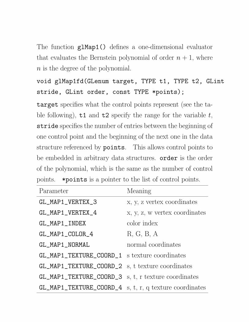
2

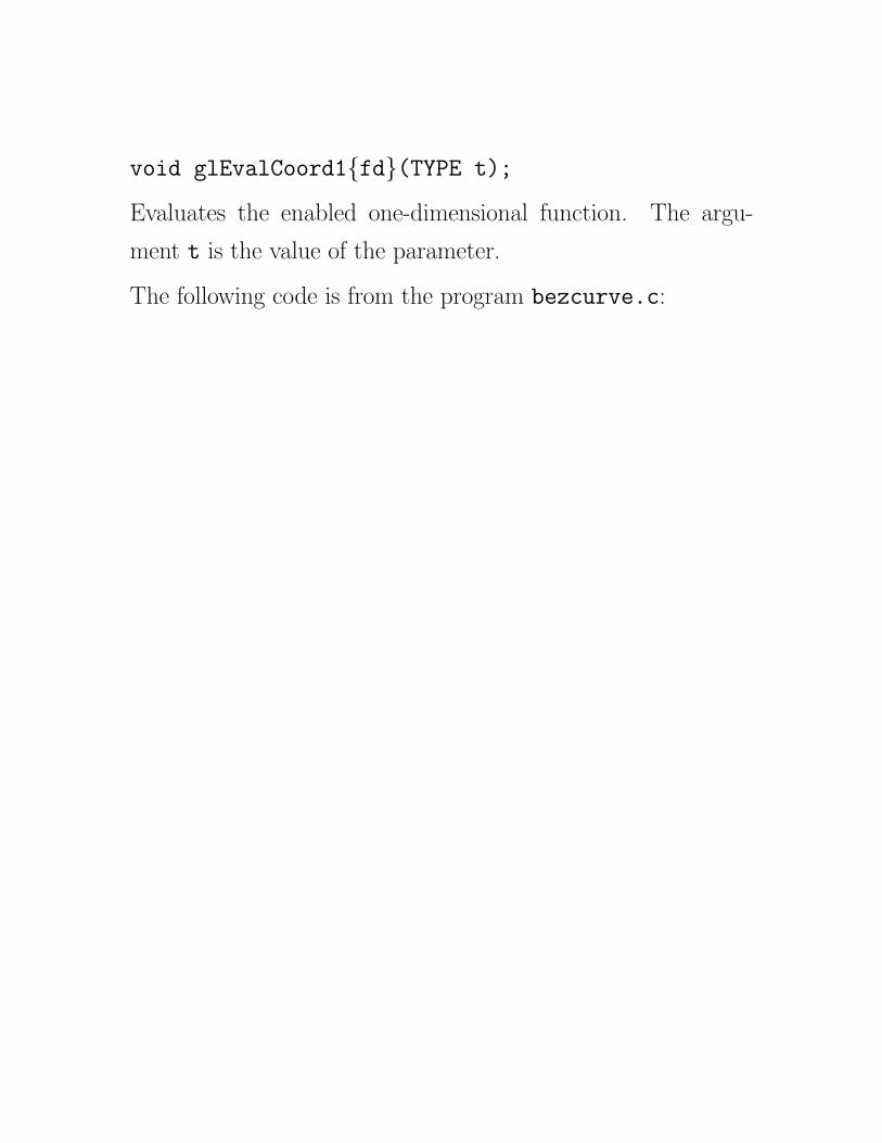
void glEvalCoord1{fd}(TYPE t);

void glEvalCoord1{fd}(TYPE t);
Evaluates the enabled one-dimensional function.

void glEvalCoord1{fd}(TYPE t);
Evaluates the enabled one-dimensional function. The argu-
ment t is the value of the parameter.
void glEvalCoord1{fd}(TYPE t);
Evaluates the enabled one-dimensional function. The argu-
ment t is the value of the parameter.
The following code is from the program bezcurve.c:

void glEvalCoord1{fd}(TYPE t);
Evaluates the enabled one-dimensional function. The argu-
ment t is the value of the parameter.
The following code is from the program bezcurve.c:
#define STEPS 5

void glEvalCoord1{fd}(TYPE t);
Evaluates the enabled one-dimensional function. The argu-
ment t is the value of the parameter.
The following code is from the program bezcurve.c:
#define STEPS 5
GLfloat ctrlpts[4][3] = {
{ -4.0, -4.0, 0.0}, { -2.0, 4.0, 0.0},
{2.0, -4.0, 0.0}, {4.0, 4.0, 0.0}};

void glEvalCoord1{fd}(TYPE t);
Evaluates the enabled one-dimensional function. The argu-
ment t is the value of the parameter.
The following code is from the program bezcurve.c:
#define STEPS 5
GLfloat ctrlpts[4][3] = {
{ -4.0, -4.0, 0.0}, { -2.0, 4.0, 0.0},
{2.0, -4.0, 0.0}, {4.0, 4.0, 0.0}};
void init(void)
{
glClearColor(0.0, 0.0, 0.0, 0.0);
glShadeModel(GL_FLAT);
glMap1f(GL_MAP1_VERTEX_3, 0.0, 1.0,
3, 4, &ctrlpts[0][0]);
glEnable(GL_MAP1_VERTEX_3);
}
Note: the stride parameter is 3, while order is set to 4 (the
degree is 3).
3
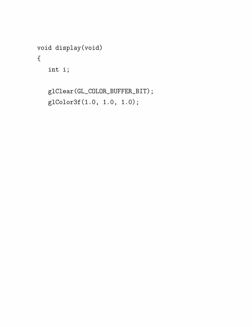
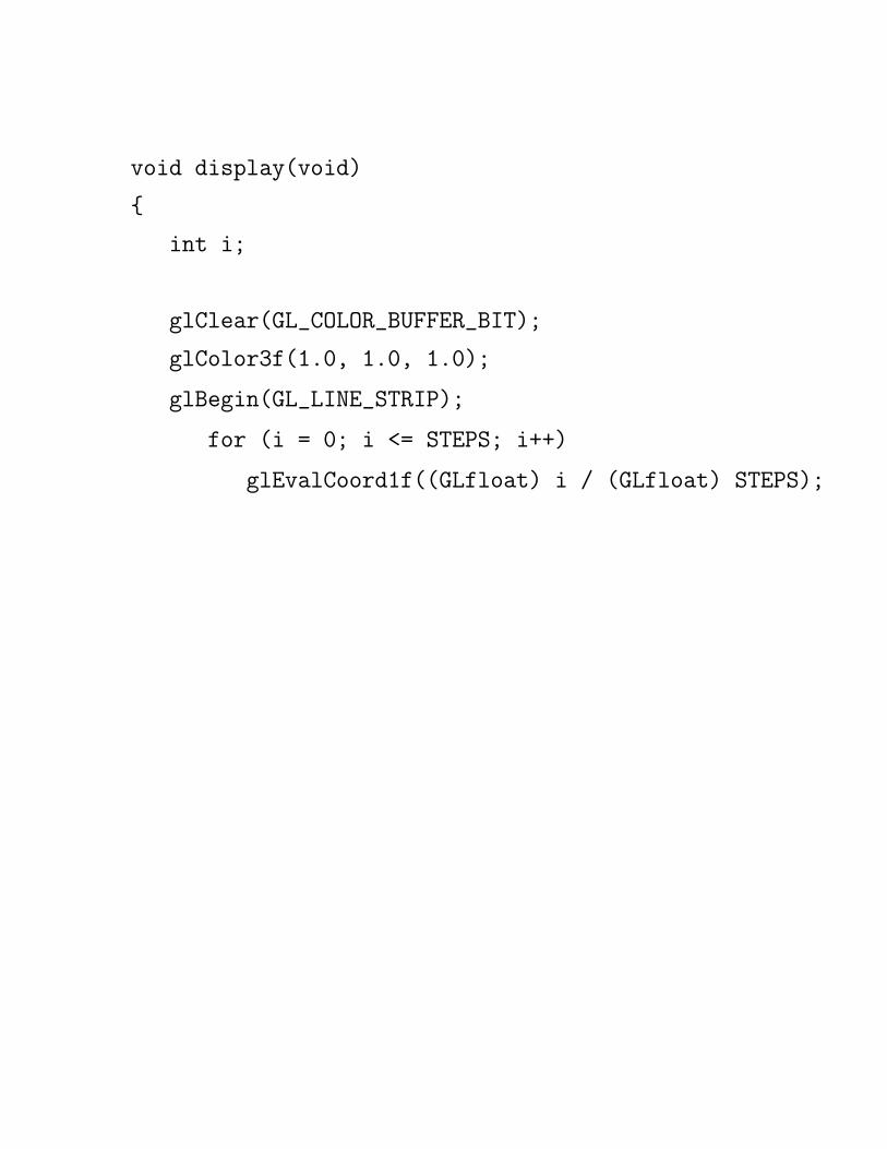
void display(void)
{
int i;
glClear(GL_COLOR_BUFFER_BIT);
glColor3f(1.0, 1.0, 1.0);

void display(void)
{
int i;
glClear(GL_COLOR_BUFFER_BIT);
glColor3f(1.0, 1.0, 1.0);
glBegin(GL_LINE_STRIP);

void display(void)
{
int i;
glClear(GL_COLOR_BUFFER_BIT);
glColor3f(1.0, 1.0, 1.0);
glBegin(GL_LINE_STRIP);
for (i = 0; i <= STEPS; i++)
void display(void)
{
int i;
glClear(GL_COLOR_BUFFER_BIT);
glColor3f(1.0, 1.0, 1.0);
glBegin(GL_LINE_STRIP);
for (i = 0; i <= STEPS; i++)
glEvalCoord1f((GLfloat) i / (GLfloat) STEPS);

void display(void)
{
int i;
glClear(GL_COLOR_BUFFER_BIT);
glColor3f(1.0, 1.0, 1.0);
glBegin(GL_LINE_STRIP);
for (i = 0; i <= STEPS; i++)
glEvalCoord1f((GLfloat) i / (GLfloat) STEPS);
glEnd();
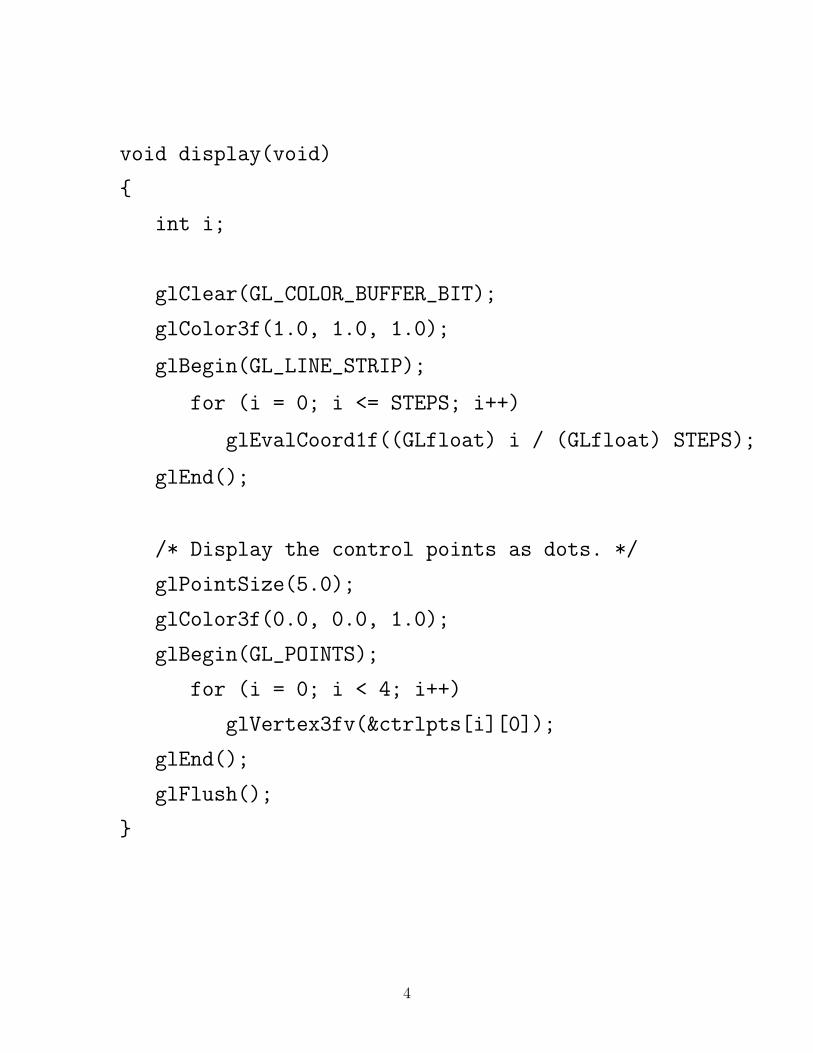
void display(void)
{
int i;
glClear(GL_COLOR_BUFFER_BIT);
glColor3f(1.0, 1.0, 1.0);
glBegin(GL_LINE_STRIP);
for (i = 0; i <= STEPS; i++)
glEvalCoord1f((GLfloat) i / (GLfloat) STEPS);
glEnd();
/* Display the control points as dots. */
glPointSize(5.0);
glColor3f(0.0, 0.0, 1.0);
glBegin(GL_POINTS);
for (i = 0; i < 4; i++)
glVertex3fv(&ctrlpts[i][0]);
glEnd();
glFlush();
}
4

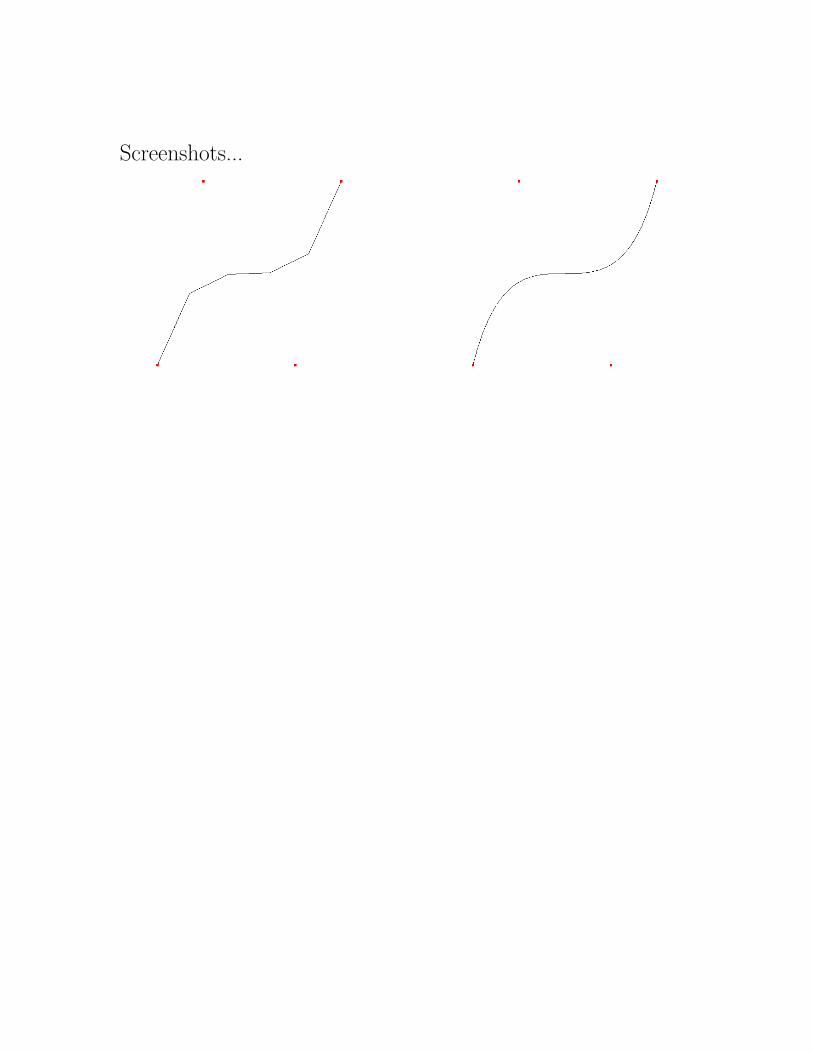
Screenshots...
Screenshots...

Screenshots...
On the left, the constant STEPS is set to 5; on the right it is set
to 30.
5

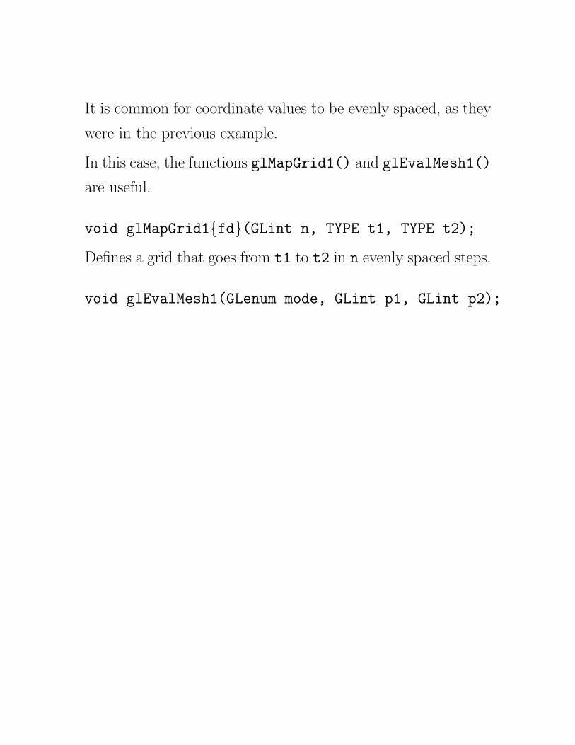
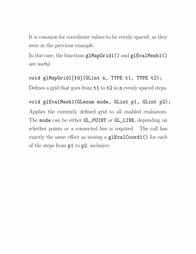
It is common for coordinate values to be evenly spaced, as they
were in the previous example.

It is common for coordinate values to be evenly spaced, as they
were in the previous example.
In this case, the functions glMapGrid1() and glEvalMesh1()
are useful.
It is common for coordinate values to be evenly spaced, as they
were in the previous example.
In this case, the functions glMapGrid1() and glEvalMesh1()
are useful.
void glMapGrid1{fd}(GLint n, TYPE t1, TYPE t2);

It is common for coordinate values to be evenly spaced, as they
were in the previous example.
In this case, the functions glMapGrid1() and glEvalMesh1()
are useful.
void glMapGrid1{fd}(GLint n, TYPE t1, TYPE t2);
Defines a grid that goes from t1 to t2 in n evenly spaced steps.
It is common for coordinate values to be evenly spaced, as they
were in the previous example.
In this case, the functions glMapGrid1() and glEvalMesh1()
are useful.
void glMapGrid1{fd}(GLint n, TYPE t1, TYPE t2);
Defines a grid that goes from t1 to t2 in n evenly spaced steps.
void glEvalMesh1(GLenum mode, GLint p1, GLint p2);
Applies the currently defined grid to all enabled evaluators.
The mode can be either GL_POINT or GL_LINE, depending on
whether points or a connected line is required.
It is common for coordinate values to be evenly spaced, as they
were in the previous example.
In this case, the functions glMapGrid1() and glEvalMesh1()
are useful.
void glMapGrid1{fd}(GLint n, TYPE t1, TYPE t2);
Defines a grid that goes from t1 to t2 in n evenly spaced steps.
void glEvalMesh1(GLenum mode, GLint p1, GLint p2);
Applies the currently defined grid to all enabled evaluators.
The mode can be either GL_POINT or GL_LINE, depending on
whether points or a connected line is required. The call has
exactly the same effect as issuing a glEvalCoord1() for each
of the steps from p1 to p2, inclusive.
6

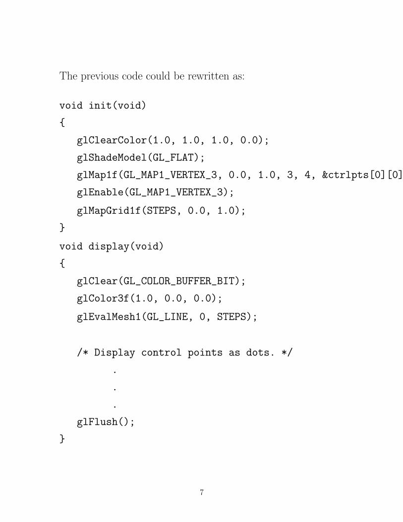
The previous code could be rewritten as:

The previous code could be rewritten as:
void init(void)
{
glClearColor(1.0, 1.0, 1.0, 0.0);
glShadeModel(GL_FLAT);
glMap1f(GL_MAP1_VERTEX_3, 0.0, 1.0, 3, 4, &ctrlpts[0][0]);
glEnable(GL_MAP1_VERTEX_3);

The previous code could be rewritten as:
void init(void)
{
glClearColor(1.0, 1.0, 1.0, 0.0);
glShadeModel(GL_FLAT);
glMap1f(GL_MAP1_VERTEX_3, 0.0, 1.0, 3, 4, &ctrlpts[0][0]);
glEnable(GL_MAP1_VERTEX_3);
glMapGrid1f(STEPS, 0.0, 1.0);
}

The previous code could be rewritten as:
void init(void)
{
glClearColor(1.0, 1.0, 1.0, 0.0);
glShadeModel(GL_FLAT);
glMap1f(GL_MAP1_VERTEX_3, 0.0, 1.0, 3, 4, &ctrlpts[0][0]);
glEnable(GL_MAP1_VERTEX_3);
glMapGrid1f(STEPS, 0.0, 1.0);
}
void display(void)
{
glClear(GL_COLOR_BUFFER_BIT);
glColor3f(1.0, 0.0, 0.0);
glEvalMesh1(GL_LINE, 0, STEPS);
/* Display control points as dots. */
.
.
.
glFlush();
}
7

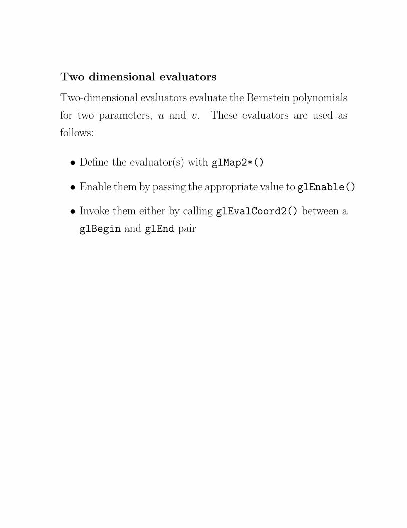
Two dimensional evaluators

Two dimensional evaluators
Two-dimensional evaluators evaluate the Bernstein polynomials
for two parameters, u and v.
Two dimensional evaluators
Two-dimensional evaluators evaluate the Bernstein polynomials
for two parameters, u and v. These evaluators are used as
follows:

Two dimensional evaluators
Two-dimensional evaluators evaluate the Bernstein polynomials
for two parameters, u and v. These evaluators are used as
follows:
• Define the evaluator(s) with glMap2*()

Two dimensional evaluators
Two-dimensional evaluators evaluate the Bernstein polynomials
for two parameters, u and v. These evaluators are used as
follows:
• Define the evaluator(s) with glMap2*()
• Enable them by passing the appropriate value to glEnable()
Two dimensional evaluators
Two-dimensional evaluators evaluate the Bernstein polynomials
for two parameters, u and v. These evaluators are used as
follows:
• Define the evaluator(s) with glMap2*()
• Enable them by passing the appropriate value to glEnable()
• Invoke them either by calling glEvalCoord2() between a
glBegin and glEnd pair

Two dimensional evaluators
Two-dimensional evaluators evaluate the Bernstein polynomials
for two parameters, u and v. These evaluators are used as
follows:
• Define the evaluator(s) with glMap2*()
• Enable them by passing the appropriate value to glEnable()
• Invoke them either by calling glEvalCoord2() between a
glBegin and glEnd pair, or by specifying and applying a
mesh with glMapGrid2() and glEvalMesh2().
8

void glMap2{fd}(GLenum target, TYPE u1, TYPE u2, GLint
ustride, GLint uorder, TYPE v1, TYPE v2, GLint vstride,
GLint vorder, TYPE *points)

void glMap2{fd}(GLenum target, TYPE u1, TYPE u2, GLint
ustride, GLint uorder, TYPE v1, TYPE v2, GLint vstride,
GLint vorder, TYPE *points)
The target parameter is as shown in the earlier table, except
MAP1 is replaced by MAP2.

void glMap2{fd}(GLenum target, TYPE u1, TYPE u2, GLint
ustride, GLint uorder, TYPE v1, TYPE v2, GLint vstride,
GLint vorder, TYPE *points)
The target parameter is as shown in the earlier table, except
MAP1 is replaced by MAP2. u1, u2, v1, and v2 are the ranges
for u and v.

void glMap2{fd}(GLenum target, TYPE u1, TYPE u2, GLint
ustride, GLint uorder, TYPE v1, TYPE v2, GLint vstride,
GLint vorder, TYPE *points)
The target parameter is as shown in the earlier table, except
MAP1 is replaced by MAP2. u1, u2, v1, and v2 are the ranges
for u and v. ustride and vstride are the “distance” to the
next u and v values in the array of control points.

void glMap2{fd}(GLenum target, TYPE u1, TYPE u2, GLint
ustride, GLint uorder, TYPE v1, TYPE v2, GLint vstride,
GLint vorder, TYPE *points)
The target parameter is as shown in the earlier table, except
MAP1 is replaced by MAP2. u1, u2, v1, and v2 are the ranges
for u and v. ustride and vstride are the “distance” to the
next u and v values in the array of control points. uorder and
vorder are the order parameters, which also give the number
of control points: uorder × vorder.
For example, you could have control points for a number of
different shapes stored in a single array
GLfloat ctrlpts[100][100][3];
To select the 4 × 4 subset (assume uorder = vorder = 4)
starting at [20][10], you would specify that...
ustride should be 3*100 and vstride should be 3 (C stores
arrays in row major order).
*points should be set to &ctrlpts[20][10][0].
9

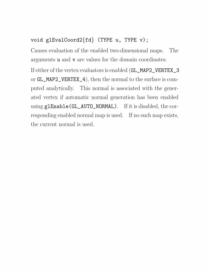
void glEvalCoord2{fd} (TYPE u, TYPE v);

void glEvalCoord2{fd} (TYPE u, TYPE v);
Causes evaluation of the enabled two-dimensional maps.

void glEvalCoord2{fd} (TYPE u, TYPE v);
Causes evaluation of the enabled two-dimensional maps. The
arguments u and v are values for the domain coordinates.

void glEvalCoord2{fd} (TYPE u, TYPE v);
Causes evaluation of the enabled two-dimensional maps. The
arguments u and v are values for the domain coordinates.
If either of the vertex evaluators is enabled (GL_MAP2_VERTEX_3
or GL_MAP2_VERTEX_4), then the normal to the surface is com-
puted analytically.

void glEvalCoord2{fd} (TYPE u, TYPE v);
Causes evaluation of the enabled two-dimensional maps. The
arguments u and v are values for the domain coordinates.
If either of the vertex evaluators is enabled (GL_MAP2_VERTEX_3
or GL_MAP2_VERTEX_4), then the normal to the surface is com-
puted analytically. This normal is associated with the gener-
ated vertex if automatic normal generation has been enabled
using glEnable(GL_AUTO_NORMAL).

void glEvalCoord2{fd} (TYPE u, TYPE v);
Causes evaluation of the enabled two-dimensional maps. The
arguments u and v are values for the domain coordinates.
If either of the vertex evaluators is enabled (GL_MAP2_VERTEX_3
or GL_MAP2_VERTEX_4), then the normal to the surface is com-
puted analytically. This normal is associated with the gener-
ated vertex if automatic normal generation has been enabled
using glEnable(GL_AUTO_NORMAL). If it is disabled, the cor-
responding enabled normal map is used.
void glEvalCoord2{fd} (TYPE u, TYPE v);
Causes evaluation of the enabled two-dimensional maps. The
arguments u and v are values for the domain coordinates.
If either of the vertex evaluators is enabled (GL_MAP2_VERTEX_3
or GL_MAP2_VERTEX_4), then the normal to the surface is com-
puted analytically. This normal is associated with the gener-
ated vertex if automatic normal generation has been enabled
using glEnable(GL_AUTO_NORMAL). If it is disabled, the cor-
responding enabled normal map is used. If no such map exists,
the current normal is used.
10

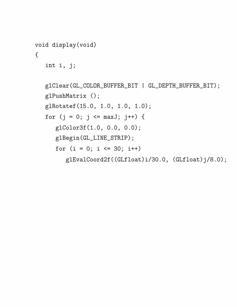
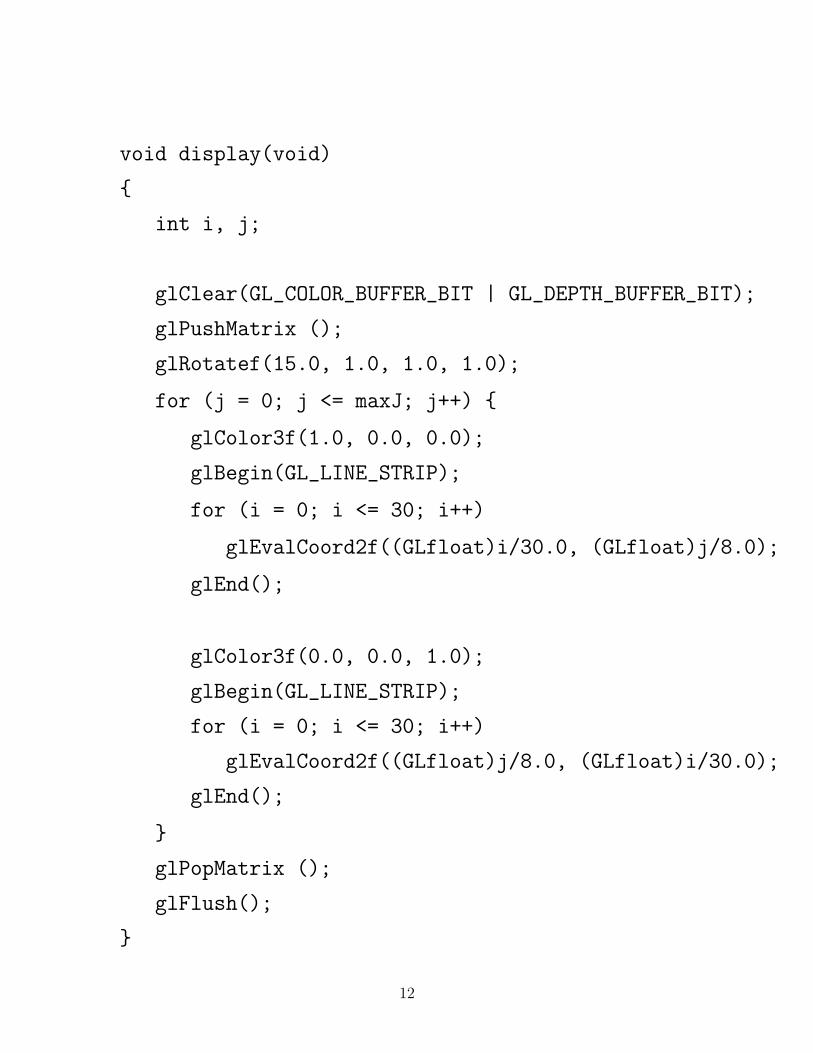
The following code is from the example bezsurf2.c.
The following code is from the example bezsurf2.c. Nine
curved lines are drawn in each direction, with each one com-
posed of 30 segments.

The following code is from the example bezsurf2.c. Nine
curved lines are drawn in each direction, with each one com-
posed of 30 segments. The red lines vary in u, the blue ones
vary in v.

The following code is from the example bezsurf2.c. Nine
curved lines are drawn in each direction, with each one com-
posed of 30 segments. The red lines vary in u, the blue ones
vary in v. (The parameter maxJ is controlled by the user to
illustrate the drawing order).

The following code is from the example bezsurf2.c. Nine
curved lines are drawn in each direction, with each one com-
posed of 30 segments. The red lines vary in u, the blue ones
vary in v. (The parameter maxJ is controlled by the user to
illustrate the drawing order).
GLfloat ctrlpoints[4][4][3] = {
{{-1.5, -1.5, 4.0}, {-0.5, -1.5, 2.0},
{0.5, -1.5, -1.0}, {1.5, -1.5, 2.0}},
{{-1.5, -0.5, 1.0}, {-0.5, -0.5, 3.0},
{0.5, -0.5, 0.0}, {1.5, -0.5, -1.0}},
{{-1.5, 0.5, 4.0}, {-0.5, 0.5, 0.0},
{0.5, 0.5, 3.0}, {1.5, 0.5, 4.0}},
{{-1.5, 1.5, -2.0}, {-0.5, 1.5, -2.0},
{0.5, 1.5, 0.0}, {1.5, 1.5, -1.0}}
};
11

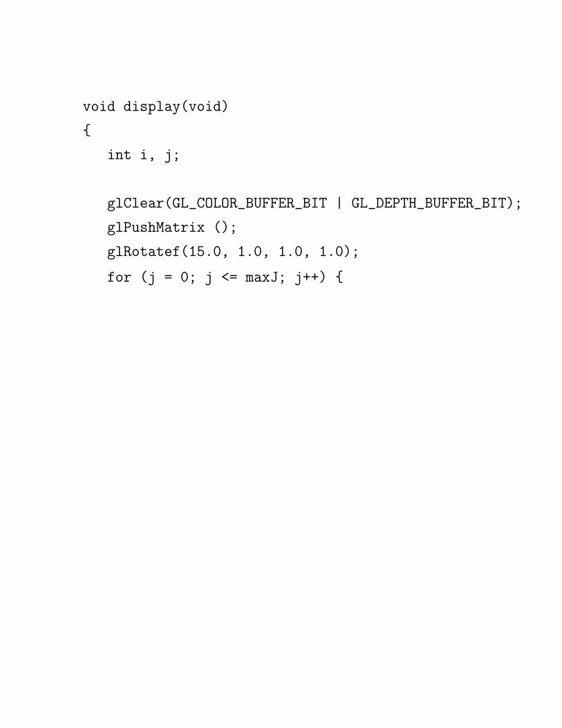
void display(void)
{
int i, j;
glClear(GL_COLOR_BUFFER_BIT | GL_DEPTH_BUFFER_BIT);
glPushMatrix ();
glRotatef(15.0, 1.0, 1.0, 1.0);
void display(void)
{
int i, j;
glClear(GL_COLOR_BUFFER_BIT | GL_DEPTH_BUFFER_BIT);
glPushMatrix ();
glRotatef(15.0, 1.0, 1.0, 1.0);
for (j = 0; j <= maxJ; j++) {

void display(void)
{
int i, j;
glClear(GL_COLOR_BUFFER_BIT | GL_DEPTH_BUFFER_BIT);
glPushMatrix ();
glRotatef(15.0, 1.0, 1.0, 1.0);
for (j = 0; j <= maxJ; j++) {
glColor3f(1.0, 0.0, 0.0);
glBegin(GL_LINE_STRIP);

void display(void)
{
int i, j;
glClear(GL_COLOR_BUFFER_BIT | GL_DEPTH_BUFFER_BIT);
glPushMatrix ();
glRotatef(15.0, 1.0, 1.0, 1.0);
for (j = 0; j <= maxJ; j++) {
glColor3f(1.0, 0.0, 0.0);
glBegin(GL_LINE_STRIP);
for (i = 0; i <= 30; i++)
void display(void)
{
int i, j;
glClear(GL_COLOR_BUFFER_BIT | GL_DEPTH_BUFFER_BIT);
glPushMatrix ();
glRotatef(15.0, 1.0, 1.0, 1.0);
for (j = 0; j <= maxJ; j++) {
glColor3f(1.0, 0.0, 0.0);
glBegin(GL_LINE_STRIP);
for (i = 0; i <= 30; i++)
glEvalCoord2f((GLfloat)i/30.0, (GLfloat)j/8.0);

void display(void)
{
int i, j;
glClear(GL_COLOR_BUFFER_BIT | GL_DEPTH_BUFFER_BIT);
glPushMatrix ();
glRotatef(15.0, 1.0, 1.0, 1.0);
for (j = 0; j <= maxJ; j++) {
glColor3f(1.0, 0.0, 0.0);
glBegin(GL_LINE_STRIP);
for (i = 0; i <= 30; i++)
glEvalCoord2f((GLfloat)i/30.0, (GLfloat)j/8.0);
glEnd();

void display(void)
{
int i, j;
glClear(GL_COLOR_BUFFER_BIT | GL_DEPTH_BUFFER_BIT);
glPushMatrix ();
glRotatef(15.0, 1.0, 1.0, 1.0);
for (j = 0; j <= maxJ; j++) {
glColor3f(1.0, 0.0, 0.0);
glBegin(GL_LINE_STRIP);
for (i = 0; i <= 30; i++)
glEvalCoord2f((GLfloat)i/30.0, (GLfloat)j/8.0);
glEnd();
glColor3f(0.0, 0.0, 1.0);
glBegin(GL_LINE_STRIP);
for (i = 0; i <= 30; i++)
glEvalCoord2f((GLfloat)j/8.0, (GLfloat)i/30.0);
glEnd();
}
glPopMatrix ();
glFlush();
}
12

void init(void)
{
glClearColor (0.0, 0.0, 0.0, 0.0);

void init(void)
{
glClearColor (0.0, 0.0, 0.0, 0.0);
glMap2f(GL_MAP2_VERTEX_3, 0, 1, 3, 4,
0, 1, 12, 4, &ctrlpoints[0][0][0]);

void init(void)
{
glClearColor (0.0, 0.0, 0.0, 0.0);
glMap2f(GL_MAP2_VERTEX_3, 0, 1, 3, 4,
0, 1, 12, 4, &ctrlpoints[0][0][0]);
glEnable(GL_MAP2_VERTEX_3);

void init(void)
{
glClearColor (0.0, 0.0, 0.0, 0.0);
glMap2f(GL_MAP2_VERTEX_3, 0, 1, 3, 4,
0, 1, 12, 4, &ctrlpoints[0][0][0]);
glEnable(GL_MAP2_VERTEX_3);
glEnable(GL_DEPTH_TEST);
glShadeModel(GL_FLAT);
}
Screenshot...

void init(void)
{
glClearColor (0.0, 0.0, 0.0, 0.0);
glMap2f(GL_MAP2_VERTEX_3, 0, 1, 3, 4,
0, 1, 12, 4, &ctrlpoints[0][0][0]);
glEnable(GL_MAP2_VERTEX_3);
glEnable(GL_DEPTH_TEST);
glShadeModel(GL_FLAT);
}
Screenshot...
13

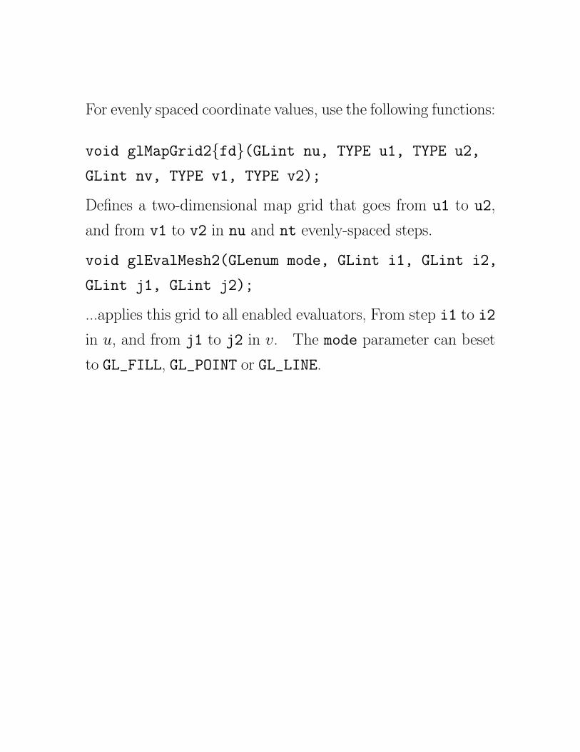
For evenly spaced coordinate values, use the following functions:

For evenly spaced coordinate values, use the following functions:
void glMapGrid2{fd}(GLint nu, TYPE u1, TYPE u2,
GLint nv, TYPE v1, TYPE v2);

For evenly spaced coordinate values, use the following functions:
void glMapGrid2{fd}(GLint nu, TYPE u1, TYPE u2,
GLint nv, TYPE v1, TYPE v2);
Defines a two-dimensional map grid that goes from u1 to u2,
and from v1 to v2 in nu and nt evenly-spaced steps.

For evenly spaced coordinate values, use the following functions:
void glMapGrid2{fd}(GLint nu, TYPE u1, TYPE u2,
GLint nv, TYPE v1, TYPE v2);
Defines a two-dimensional map grid that goes from u1 to u2,
and from v1 to v2 in nu and nt evenly-spaced steps.
void glEvalMesh2(GLenum mode, GLint i1, GLint i2,
GLint j1, GLint j2);
...applies this grid to all enabled evaluators, From step i1 to i2
in u, and from j1 to j2 in v.
For evenly spaced coordinate values, use the following functions:
void glMapGrid2{fd}(GLint nu, TYPE u1, TYPE u2,
GLint nv, TYPE v1, TYPE v2);
Defines a two-dimensional map grid that goes from u1 to u2,
and from v1 to v2 in nu and nt evenly-spaced steps.
void glEvalMesh2(GLenum mode, GLint i1, GLint i2,
GLint j1, GLint j2);
...applies this grid to all enabled evaluators, From step i1 to i2
in u, and from j1 to j2 in v. The mode parameter can beset
to GL_FILL, GL_POINT or GL_LINE.

For evenly spaced coordinate values, use the following functions:
void glMapGrid2{fd}(GLint nu, TYPE u1, TYPE u2,
GLint nv, TYPE v1, TYPE v2);
Defines a two-dimensional map grid that goes from u1 to u2,
and from v1 to v2 in nu and nt evenly-spaced steps.
void glEvalMesh2(GLenum mode, GLint i1, GLint i2,
GLint j1, GLint j2);
...applies this grid to all enabled evaluators, From step i1 to i2
in u, and from j1 to j2 in v. The mode parameter can beset
to GL_FILL, GL_POINT or GL_LINE. GL_FILL generates filled
polygons.
The example bezmesh.c illustrates these commands.
14


![OpenGL Curves & Surfaces. Where u varies in some domain (say [0,1]). A Bezier surface patch is a vector-valued function of two variables Evaluators A.](https://static.documents.pub/doc/80x56/56649d445503460f94a207f4/opengl-curves-surfaces-where-u-varies-in-some-domain-say-01-a-bezier.jpg)


