UNIVERSITY OF ADELAIDE FACULTY OF ENGINEERING,COMPUTER &MATHEMATICAL SCIENCES SCHOOL OF MECHANICAL ENGINEERING MECH ENG 4135: MECHATRONICS HONOURS PROJECT 899: B ALLBOT Preliminary Report AUTHORS : Justin F ONG Simon UPPILL S UPERVISOR: Ben C AZZOLATO May 22, 2009
Transcript
UNIVERSITY OF ADELAIDE
FACULTY OF ENGINEERING, COMPUTER & MATHEMATICAL SCIENCES
SCHOOL OF MECHANICAL ENGINEERING
MECH ENG 4135: MECHATRONICS HONOURS PROJECT
899: BALLBOT
Preliminary Report
AUTHORS:
Justin FONG
Simon UPPILL
SUPERVISOR:
Ben CAZZOLATO
May 22, 2009
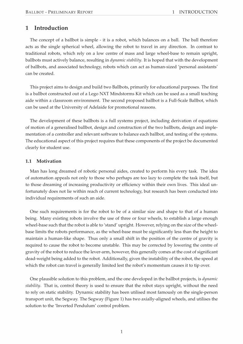
BALLBOT - PRELIMINARY REPORT
Executive Summary
A ballbot is a robot which utilises the concept of dynamic stability to remain upright and bal-
anced on a ball. This involves using control theory to actuate the ball and balance, rather than
relying on gravity and a large wheel base. Only two ballbots had been constructed at the com-
mencement of this project - the first by the Robotics Institute at Carnegie Mellon University (CMU)
in 2006, and the second by Tohoku Gakuin University (TGU) in 2008. During the course of the
project, a Lego ballbot has also been created, by Yorihisa Yamamoto.
This project aims to produce two Ballbots, a small scale version constructed from a Lego Mind-
storms Kit, and a larger ballbot with dimensions approximating that of a human being, for use
as promotional and teaching tools at the University of Adelaide. Development of the Ballbots
required derivation of the dynamics, construction of each of the ballbots, and design and imple-
mentation of a controller to stabilise the ballbots.
Derivation of the equations of motion of the ballbot system was performed using the Lagrangian
approach on a simplified ballbot model, resulting in a linearised state space form of the dynamics
of this simplified ballbot model.
Construction of a Lego Ballbot has been completed, using the Lego NXT Mindstorms kit and
other available Lego parts. This Ballbot uses a simple ‘Inverse Mouse-Ball Drive’, developed by
Lauwers et al. (2006), where the ball is actuated by driven wheels on orthogonal sides of the ball.
Design of a Full Scale Ballbot is in progress, and is loosely based on the Lego Ballbot. However, the
Full Scale Ballbot design uses four motors to actuate the ball using omni-wheels, in an arrangement
similar to that proposed by Wu and Hwang (2008). This design allows for greater flexibility, such
as the ability to use different sized balls, while still allowing for the ‘Inverse Mouse-Ball Drive’.
A controller for the ballbot system has been developed using a full state feedback approach,
based on a controller developed by Yamamoto (2008) for a two wheeled balancing robot. This con-
troller has been implemented on the Lego Ballbot, but has not yet been successful at balancing the
Ballbot. Further testing and controller modification will be performed to achieve a stable Ballbot.
Upon achievement of this aim the controller will be extended to allow for command tracking using
a handheld game controller.
The design of the Full Scale Ballbot is yet to be finalised, at which time construction of the Full
Scale Ballbot will commence. Once construction is complete the previously developed controller
will be modified and implemented. This process aims to result in a stable Full Scale Ballbot with
command tracking capabilities.
i
BALLBOT - PRELIMINARY REPORT
Acknowledgements
The authors of this report would like to thank Associate Professor Dr Benjamin Cazzolato for
his guidance, aide and support during the project.
We would also like to thank the 2009 University of Adelaide Open Day Creativity and Innova-
tion Fund for providing funding for this Ballbot Project.
Furthermore we would like to acknowledge the University of Adelaide Mechanical workshop
staff, particularly Richard Pateman for his advice on structural design, and Phil Schmidt for his
assistance with electrical design.
Finally, thanks go to Yorihisa Yamamoto for making available his NXTway-GS and NXT Ballbot
controllers and documentation, and for answering our queries related to these.
ii
BALLBOT - PRELIMINARY REPORT
Disclaimer
The content of this report is entirely the work of the following students from the University of
Adelaide. Any content obtained from other sources has been referenced accordingly.
The concepts were then evaluated in Table 4 based on the following weighted criteria:
• Construction (/10): How easily or simply the concept can be constructed using Lego
• Control (/10): How easily the concept can be integrated into the currently derived equations
of motion and control strategy.
• Friction (/5): Anticipated friction of the concept (friction is undesirable)
• Potential (/5): How easily the concept could be adapted to provide additional functionality,
such as yaw control.
• Cost (/10): Does the concept require additional parts beyond those discussed in Section 4.1,
either standard Lego parts or other parts.
• Other (±5): Any other advantages or disadvantages
24
BA
LL
BO
T-
PR
EL
IMIN
AR
YR
EP
OR
T4
TH
EL
EG
OB
AL
LB
OT
Table 4: Decision Matrix for Lego Ballbot Drive MechanismConcept Construction /10 Control /10 Friction /5 Potential /5 Cost /10 Other +-5 Total Score1a (one drivenwheel per pair)
Simple Simple High due to frictionpoint and orthogonalwheels
Low Low Applied actuation is nota pure torque
10 10 0 0 10 -2 281b (all wheelsdriven)
Relatively Simple Some difficulty as pairsof wheels must be syn-chronised
High due to frictionpoint and orthogonalwheels
Low Requires an additionalservo drive (beyondthose included in thekit)
Applied actuation is apure torque
8 8 0 0 6 +2 24
2The use of a non-standard Lego part addsdifficulty. Asymmetriesalso add difficulty
Simple Low due to use of omni-wheels
High - location of om-niwheels will provideyaw control from theball
Requires the use of om-niwheels (non standardLego part)
Applied actuation is nota pure torque
3 10 5 5 4 -2 253a (one drivenwheel per pair)
The use of a non-standard Lego partadds difficulty
Simple Low due to use of omni-wheels
Moderate - use of omni-wheels allow for easieraddition of yaw controlfrom the ball
Requires the use of om-niwheels (non standardLego part)
Applied actuation is nota pure torque
5 10 5 3 4 -2 253b (all wheelsdriven)
The use of a non-standard Lego partadds difficulty
Simple Low due to use of omni-wheels
Moderate - use of omni-wheels allow for easieraddition of yaw controlfrom the ball
Requires a forth servodrive and the use of om-niwheels (non standardLego part)
Applied actuation is nota pure torque (but less-ened)
5 10 5 3 0 -1 22
4The use of a non-standard Lego partadds difficulty. Nonorthogonal and angledwheels adds difficulty
High difficulty as theremust be a conversionbetween orthogonaltorques and the threewheels
Low due to use of omni-wheels
High - location of om-niwheels will provideyaw control from theball
Requires the use of om-niwheels (non standardLego part)
Applied actuation is nota pure torque (but less-ened)
0 4 5 5 4 -1 17
5The use of a non-standard Lego partadds difficulty. Angledwheels add difficulty.
Moderate difficulty aspairs of wheels must besynchronised
Low due to use of omni-wheels
High - location of om-niwheels will provideyaw control from theball
Requires a forth servodrive and the use of om-niwheels (non standardLego part)
Applied actuation is nota pure torque (but less-ened)
3 8 5 5 0 -1 20
25
BALLBOT - PRELIMINARY REPORT 4 THE LEGO BALLBOT
Based upon this evaluation, the concept of using pairs of orthogonal wheels (one driven, one
idler) mounted at the ball centre axis was selected.
4.2.2 Required Components
Based upon the selected drive mechanism and anticipated controller requirements, the required
components were determined. The selected drive mechanism required two servo motors to drive
the ball and the controller requires sensors to measure the angle and/or angular speed of the body
and the ball in relation to the body. The Lego servo motors used include an encoder which will
provide the angle of the ball relative to the body, so additional sensors were only required for the
body angle. This can be achieved through the use of the gyros and accelerometers, as discussed in
Section 2.2.3. It was also desired that the ballbot be able to detect when the ball is present, so the
controller will only run when the Lego Ballbot is atop the ball. Thus it was determined that the
Lego Ballbot would require the following components:
• The NXT brick, to run the controller program
• Two Lego servo motors, with encoders
• A sensor block able to detect the body angle or angular speed, including a HiTechnic Gyro-
scopic Sensors for each direction of tip and/or a HiTechnic 3-axis Accelerometer
• A sensor to detect the ball
4.2.3 Lego Ballbot Layout
The layout of the Lego Ballbot was determined by considering the best location of each of the
required components. These are as follows:
• NXT Brick: Top of the ballbot. A higher centre of mass will make the ballbot easier to stabilise,
as this effectively makes the ballbot fall slower. Raising the NXT brick will raise the centre
of mass of the Lego Ballbot, as it will likely account for 25%-50% of the Lego Ballbot’s total
weight. Also, locating the NXT brick at the top of the Lego Ballbot makes it easy for the
operator to access.
• Servo Motors: As close to the drive wheels as possible to reduce compliance due to torsion
in axles and backlash due to gearing.
• Sensors to measure body angle: If accelerometers are used, these should be mounted as close
to the centre of percussion as possible to reduce noise. If gyroscopic sensors are used, location
is not important.
• Sensor to detect the ball: This will likely have to be in contact with or very close to the ball.
The layout of the Lego Ballbot was designed to satisfy these constraints as closely as possible. This
resulted in the concept design for the Lego Ballbot, shown in Figure 12
4.3 Construction of the Lego Ballbot
Following the concept design, the construction of the Lego Ballbot was undertaken. Construc-
tion was undertaken with the following aims (in order of priority):
• The layout of the Lego Ballbot matches as closely as possible to the concept design proposed
in section 4.2
26
BALLBOT - PRELIMINARY REPORT 4 THE LEGO BALLBOT
Figure 12: Layout of the Lego Ballbot
• The Lego Ballbot, where possible, uses only Lego pieces available in the NXT Mindstorms
kit, or those additional parts identified as necessary in section 4.1.
• The Lego Ballbot is well balanced, ie: the centre of mass of the Ballbot is directly over the
centre of ball when the body is vertical.
• The Lego Ballbot is as rigid as possible, as a flexible structure will result in resonances at low
frequencies.
The construction process used a trial and error iterative approach. This involved attempting to
construct the Lego Ballbot starting with the drive mechanism and working upwards, making mod-
ifications to the previous construction as required due to part availability. The modular nature of
Lego allows this, as the Lego Ballbot could easily be disassembled and reassembled with modifi-
cations at any stage during construction. This process resulted in the original Lego Ballbot. The
original design was further modified during controller development to improve performance.
4.3.1 Original Lego Ballbot
The Original Lego Ballbot was constructed following the above guidelines. The Original Lego
Ballbot included direct drive from the servo motors to the wheels and the use of gyroscopic sen-
sors to measure body angular speed. This was believed to provide adequate measurement and
actuation to allow control of the ballbot.
The first step in building the Original Lego Ballbot was the implementation of the drive mecha-
nism. The frame of the drive mechanism consisted of two U-shapes of Lego mounted orthogonally
to enclose the ball shown in Figure 13. The wheels used were selected to give high grip on the ball.
27
BALLBOT - PRELIMINARY REPORT 4 THE LEGO BALLBOT
The servo motors were mounted on opposite corners of this structure. These directly drive two
orthogonal wheels, hence providing two orthogonal torques to the ball.
(a) A Single U-Frame (b) Underneath (c) Complete
Figure 13: Lego Ballbot: The Frame for the Drive Mechanism
The second step involved extending the frame vertically to allow for sensor mounting. The
sensors used on the Original Lego Ballbot included a touch sensor to detect the ball, and gyroscopic
sensors to determine body angle. The touch sensor was mounted vertically in the centre of the
frame, as shown in Figure 14(a). This serves to vertically locate the ball, and also indicate to the
controller that the ball is present. This feature was intended to allow the controller to disable when
the Lego Ballbot is removed from the ball. The gyroscopic sensors are mounted on the frame to
provide measurements in the two planes of body tip as shown in Figure 14(b).
(a) Position of the Touch Sensor (b) Position of Gyroscope Sensors
Figure 14: Lego Ballbot: Sensor Locations
Thirdly, the NXT brick was mounted upon the top of the Lego Ballbot. Finally, additional rein-
forcement was added to increase the stiffness of the body. This resulted in the completed Original
Lego Ballbot shown in Figure 15.
4.3.2 Modifications
During controller development, several modifications were made to the Lego Ballbot with the
aim of improving performance. The modifications include:
• Replacement of the idler wheels with narrower wheels to reduce friction on the ball.
28
BALLBOT - PRELIMINARY REPORT 4 THE LEGO BALLBOT
(a) Front (b) Back
Figure 15: Lego Ballbot: Complete
• The addition of gearing between the servo motors and wheels to increase the maximum
possible ball velocity
• Increasing the height of the centre of mass of the Lego Ballbot by raising the NXT brick. This
aimed to slow the rate at which the ballbot falls over, hence making it easier to control.
• The addition of a 3-axis accelerometer to assist in measuring the body angle, as discussed in
The final Lego Ballbot with states as defined in Section 3 is shown in Figure 17.
29
BALLBOT - PRELIMINARY REPORT 4 THE LEGO BALLBOT
Figure 17: Final Lego Ballbot, showing coordinate system and states
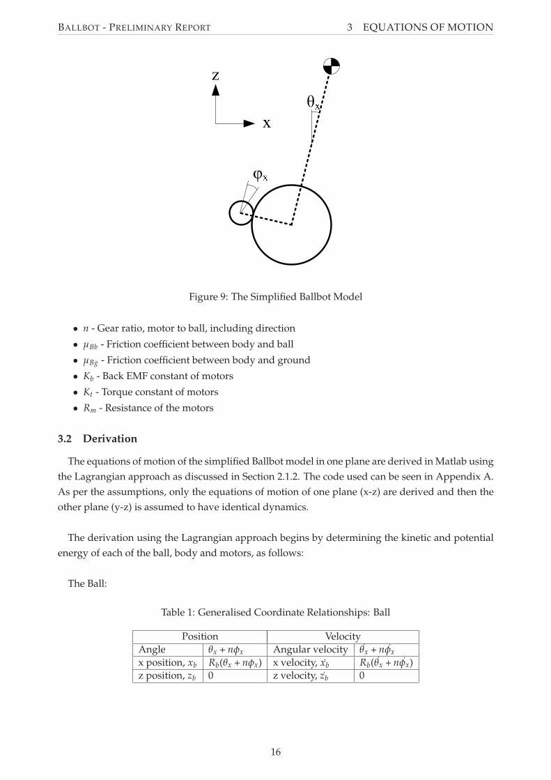
Table 5: Lego Ballbot Physical Parameters
Mass of the Body MB 0.77 kg
Height of centre of mass L 0.128 m
Mass of the Ball Mb 0.01 kg
Radius of the Ball Rb 0.026 m
Moments of Inertia of the BodyIBx 0.003677 kg.m2
IBy 0.003927 kg.m2
Moment of Inertia of the Ball Ib 0 kg.m2 (negligible)
Gear Ratio, motor to ball n −3052 ×
−2012
Moment of Inertia of the Motors and Wheels IM 2 × 10⁻⁵ kg
Friction coefficient between body and ball µBb 0.0022
Friction coefficient between body and ground µBg 0
30
BALLBOT - PRELIMINARY REPORT 5 CONTROLLER
5 Controller
The controller developed for this ballbot project was based on the controller for the NXTway-GS.
This section of the report details the analysis of the NXTway-GS controller for use in this project,
the development of the theoretical controller, simulation of the performance of this theoretical
controller, and the implementation of this theoretical controller into software for use on the NXT
brick.
5.1 Suitability of NXTway-GS Controller Program for Modification
It was decided that the controller for the ballbot project could be created by modifying the
NXTway-GS controller, documented and created by Yamamoto (2008). Two main issues were con-
sidered in assessing the suitability of modifying the NXTway-GS controller for use on the ballbot.
First, the similarities between the two systems were assessed to determine whether the NXTway-
GS controller would require major modification. Secondly, the use of Simulink for programming
was compared to other methods of programming.
The NXTway-GS controller can be modified to be used as the controller in this project. It has
already been established that the ballbot can be modelled as two independent systems of a two-
wheeled self-balancing robot, such as the NXTway-GS. Furthermore, much of the functionality
provided by the NXTway-GS controller is similar to that required for the controller in this project,
including command tracking, the use of the Lego Mindstorms Kit, and the use of the same com-
ponents (gyroscopes and servo motors). The largest fundamental difference between the two pro-
grams is that the ballbot controller will require twice as many states, and thus a large amount of
additional processing power. It was thought, given the relative simplicity of the program, the con-
troller hardware would be able to provide this. This was later confirmed due to the production
of the NXT Ballbot, also created by Yamamoto and based on the NXTway-GS controller. It was
therefore concluded that the differences between the two systems were not significant, and thus
no major modifications of the controller would be required.
The use of Simulink for programming is advantageous for the purposes of this project, due to
the fact that it the program is used in educational classes at the University of Adelaide. The avail-
ability of the ECRobot NXT Blockset for Simulink allows for easy interfacing with the sensors and
actuators used on the Lego Ballbot. The alternate method of programming the Lego Mindstorms
brick is to use the RobotC. This is a programming language based on C, developed for use with
the Lego Mindstorms kit. It was decided that using this method of programming was not as clear
as using the graphical programming language of Simulink, and thus using Simulink would serve
the project better for programming.
Therefore, it was concluded that the NXTway-GS controller would provide a good foundation
on which to base a controller for the project.
31
BALLBOT - PRELIMINARY REPORT 5 CONTROLLER
5.2 Theoretical Controller
A number of controller options were considered for the ballbot, many of which have been dis-
cussed in section 2.3. For this project, a state space controller was selected, with gains calculated
using the Linear Quadratic Regulator (LQR) technique.
The LQR is a well-understood technique, and is taught in control subjects at the University of
Adelaide. In an LQR controller, the control signal is based upon the desired state xref and the actual
state of the system x ie:
u = k(xref − x) = kex
LQR attempts to choose gains which optimise the control signals, based on a heuristic, created
on construction. The significant disadvantage to this approach is that it is often hard to select an
appropriate quantifiable heuristic, and this choice is often superficial. Furthermore, the controller
is only a linear controller, which limits its accuracy when applied to non-linear systems such as the
ballbot. However, it was felt that an LQR controller was an appropriate choice for this system due
to its simplicity and its similarities to the CMU ballbot and NXTway-GS controller, which also use
an LQR controller (Lauwers et al., 2006, Yamamoto, 2008).
The development of a state-space LQR controller requires a linear state space model of the sys-
tem, and the calculation of the controller gains using a heuristic.
5.2.1 State Space Model of the Lego Ballbot
In order to create any controller, knowledge of the system dynamics are required. These dy-
namics were derived using suitable assumptions for a simplified ballbot in Section 3 in the form
of equations of motions. These equations of motion are applied to the Lego Ballbot using the
co-ordinates, states and physical parameters defined in Section 4.4.
The equations of motion are given in state space form x = Ax + Bu where the state vector x
consists of
• θx - The angle of the body of the ballbot relative to the vertical in the x-plane
• φx - The angle of the motor shaft relative to the body in the x-plane
• θy - The angle of the body of the ballbot relative to the vertical in the y-plane
• φy - The angle of the motor shaft relative to the body in the y-plane
• θx - The angular velocity of the body of the ballbot in the x-plane
• φx - The angular velocity of the motor shaft relative to the body in the x-plane
• θy - The angular velocity of the body of the ballbot in the y-plane
• φy - The angular velocity of the motor shaft relative to the body in the y-plane
and the control signal u consists of the two motor voltages.
32
BALLBOT - PRELIMINARY REPORT 5 CONTROLLER
These states give, in traditional control theory terms, Proportional and Derivative (PD) control.
In addition to this, we introduce two extra states to give integral control of the φx and φy states:
•∫
φx - The integral of the angle of the motor shaft relative to the body in the x-plane
•∫
φy - The integral of the angle of the motor shaft relative to the body in the y-plane
The addition of these extra states eliminates steady state error, which may be introduced due to
disturbances or noise. This approach can be seen schematically in Figure 18, and is similar to that
implemented by Yamamoto (2008).
Figure 18: Addition of Integral Control State on Ballbot Controller (adapted from Yamamoto(2008))
5.2.2 Calculating the Lego Ballbot Controller Gains
As mentioned previously, a Linear Quadratic Regular was used to calculate optimal control
gains. The heuristic developed for LQR controller requires a Q matrix, and a R matrix. The Q
matrix is a weighting matrix which indicates the desirability of each state being equal to its set
point. The R matrix is a matrix which penalises the use of larger control inputs. These matrices are
then used to find the gain matrix K in the following equation:
(31)∫ T
t[xT(τ)(Q + KTRK)x(τ)]dτ
The Q and R matrices chosen were based on those used by Yamamoto (2008) in the NXTway-GS
controller, due to the similarities between the two systems. These were then modified based on
testing.
(32)Q =
60000 0 0 0 0 0 0 0 0 0
0 1 0 0 0 0 0 0 0 0
0 0 60000 0 0 0 0 0 0 0
0 0 0 1 0 0 0 0 0 0
0 0 0 0 1 0 0 0 0 0
0 0 0 0 0 1 0 0 0 0
0 0 0 0 0 0 1 0 0 0
0 0 0 0 0 0 0 1 0 0
0 0 0 0 0 0 0 0 400 0
0 0 0 0 0 0 0 0 0 400
33
BALLBOT - PRELIMINARY REPORT 5 CONTROLLER
(33)R =
[
1000 0
0 1000
]
The Matlab lqr command was used to generate the solution to this equation, to give the gain
matrix, K. The K matrix was split up into two matrices, shown below; a 2 × 8 matrix, K f for the
non-integral states (the first 8 columns); and a 2 × 2 matrix, Ki for the control of the integral states,
allowing integral control as discussed in Section 5.2.1.
(34)K f =
[
−51.5311 −1.0674 0 0 −5.8076 −1.4144 0 0
0 0 −51.8186 −1.0686 0 0 −5.9051 −1.4165
]
(35)Ki =
[
−0.6325 0
0 −0.6325
]
5.2.3 Controller Simulation
In order to validate the controller gains, a Simulink simulation program was created. This pro-
gram can be seen in Figure 19. The simulator models the physical ballbot with the dynamics
derived in Section 3 in the ‘Ballbot’ block. It should be noted these dynamics are also used to
create the controller, thus the numerical results are only valid if the dynamics are a very good ap-
proximation of the actual ballbot dynamics. The results, however, can be used to validate that the
controller and the gains are suitable for the ballbot controller.
Figure 19: Controller Simulator Program
The simulator aims to model the controller and the dynamics of the ballbot. The saturation
control in the controller is also modelled to ensure that the signals to the motor are not beyond
their capabilities. It was also developed to accommodate commands being sent to the controller,
and disturbances to the system. Commands can be used to simulate remote control of the ballbot
from a user. Disturbances to the system may include the ballbot starting away from vertical, or
being pushed or struck whilst balancing.
34
BALLBOT - PRELIMINARY REPORT 5 CONTROLLER
The simulation results for three cases are presented in this report. All three cases operate in the
x-plane only, as the simulated controller operates in the same way in both planes, with insignificant
differences between the two. The three cases are as follows:
Case 1: The Lego Ballbot is initially placed with a body angle 3 degrees from the vertical, and
released from rest.
Case 2: The Lego Ballbot is initially vertical, and the initial angular velocity of the body is +40◦/s.
Case 3: The Lego Ballbot is given a command to move its motors at 100◦/s (equivalent to the
ballbot moving 0.09m/s) for two seconds, starting at t=1s.
The results of these simulations can be seen in Figure 20
0 1 2 3 4 5 6 7 8 9 10−4
−2
0
2
4Simulation Results
Time (t)
Bod
y A
ngle
, θ (
deg)
0 1 2 3 4 5 6 7 8 9 10
0
100
200
300
Time (t)
Mot
or A
ngle
, φ (
deg)
0 1 2 3 4 5 6 7 8 9 10
−2
0
2
4
6
Time (t)
Mot
or S
igna
l (V
)
Case 1Case 2Case 3
Figure 20: Controller Simulation Results
The results of the simulation suggest that the controller will be adequate to control the ballbot,
assuming that the derived equations of motion adequately model the ballbot’s dynamics, as the
ballbot is stabilised in the results. In particular, the motor signals do not saturate (at ±8V) for any
of the cases, which indicates that they are capable of producing enough torque and velocity to
stabilise the ballbot in these cases. Additionally, the steady state error is equal to zero for all three
cases. Thus, the simulation appears to validate the choice of controller method and the derived
gains.
35
BALLBOT - PRELIMINARY REPORT 5 CONTROLLER
5.3 Controller Implementation
The controller described in section 5.2 was implemented in Simulink, again based on the NXTway-
GS controller. The implementation included the basic setup of the program, the reading of sensors,
the actuation of the motors and the implementation of the controllers.
5.3.1 Basic Program Structure
The basic controller has three tasks, which run at different rates. These tasks can be seen in
Figure 21. The Initialisation task is used to simply calculate an offset for the gyroscope. The
gyroscopes each have an offset, which is calculated each time the Ballbot is started up. The Time
Check and Battery Average task is very simple also. It checks if the initialisation time has expired,
and reads the voltage of the battery. The battery voltage is saved so that it can be used in to scale
the PWM signal to the motors. The motors are battery voltage dependent, and thus a lower or
higher battery charge must be compensated within the program. The Balance and Drive Control
is the main part of the program. This is where the controller is used to keep the ballbot balancing,
and includes the sensor reading, data processing, controller algorithm and signal generation (for
the motors).
Application Task SubsystemsEach function−call subsystems are drived by function−call signals of the task scheduler andgenerated as OSEK task functions in the generated code using Export functions feature of RTW−EC.
Initialization Balance & Drive Control Time Check &Battery Average
task_ts2
function ()
task_ts1
function ()
task_init
function ()
task_ts2_fc
3
task_ts1_fc
2
task_init _fc
1
Figure 21: Application Subsystems of the Controller
5.3.2 Sensor Reading and State Calculations
The controller requires measured or estimated values for all states as defined in section 5.2.1.
These values are obtain using motor encoders and gyroscopes. Interfacing with these compo-
nents is simple using the ECRobot NXT Blockset for Simulink. Using these Simulink programming
blocks, the values from these inputs can be read directly and used to determine the ballbots state,
as shown in Figure 22.
The measurement of the body angle, θ, uses two HiTechnic gyroscopes - one for each plane.
The gyroscopes measure angular velocity in a single plane, in units of degrees per second, and are
mounted to the ballbot’s body. Thus, the reading from the gyroscopes can be used to measure the θ
states . A major complexity in the gyroscopes’ readings is that each gyroscope has an offset, which
must be calculated and subtracted from values measured by the gyroscopes (shown in Figure 22).
36
BALLBOT - PRELIMINARY REPORT 5 CONTROLLER
deg2rad3
pi /180
deg2rad2
−pi /180
deg2rad1
pi /180
deg2rad
pi /180
Low Path Filter 1
in out
Low Path Filter
in out
Discrete Integrator(forward euler )2
in out
Discrete Integrator(forward euler )
in out1
Discrete Derivative(backward difference )1
in out
Discrete Derivative(backward difference )
in out
Cal gyro _y_offset
gyro _y gyro _y _offset
Cal gyro _x_offset
gyro _x gyro _x_offset
X_Gyroscope
Y_Motor _Encoder
X_Motor _Encoder
Y_Gyroscope
State Vector (x)
thetaX
thetaXdot
thetaXdot
phiX
phiX
thetaY
thetaYdotthetaYdot
phiY
phiY
phiXdot
phiYdot
Figure 22: Measurement and Calculation of States
This offset is initialised during the initialisation task, using a low pass filter of the gyroscope
readings during this time. This method is not ideal as it assumes that the ballbot is held still during
this initial calibration stage (see Figure 23). However, it was considered better than initialising
the value to a constant, as each physical gyroscope has a slightly different offset value and can
be affected by other inputs and outputs, and this would be detrimental to the portability of the
controller software.
Low Path Filter Function 1−a_gc −−−−−−−−−−−−−−−− 1−a_gc*z^(−1)
Calculate gyro offset (zero point value).
Gyro Sensor Read 1Port = S2
S2
Gyro Sensor ReadPort = S1
S1
a_gc
a_gc
1−a_gc
1−a_gc
Round = Simplest
single
Round = Simplest
single
gyro_y_offset
gyro_x_offsetgyro_x_offset
gyro_y_offset
Figure 23: Calculation of the Gyroscope Offset
The offset is also continually updated while the program is running, again using a low pass filter
with a slower pole. This helps reduce the effects of a dropping battery voltage, however, assumes
37
BALLBOT - PRELIMINARY REPORT 5 CONTROLLER
that the average ballbot body angular velocity is equal to zero.
The offset is subtracted from the gyroscope reading, which is then converted from degrees per
second to radians per second to give the θ states. The θ states are simply calculated by integrating
the θ states.
The motor angle states, φ are determined by reading the value from the motor encoders. The
motor encoder programming block returns the angle of the motor shafts in degrees, and must be
converted into radians for use within the controller. The φ states are calculated by differentiating
these values, after a low pass filter is applied to remove any high-frequency noise. The construction
of the controller to measure the φ and φ states can be seen in Figure 22. The integral states used for
integral tracking,∫
φ are simply calculated by the integration of the φ values.
5.3.3 Calculation of Set Points
The controller allows the use of set points for command tracking. However, for the initial pur-
poses of this project, as documented by this Preliminary Report, the set point for all states has been
set to zero. That is, the desired position of the ballbot is directly upright, at its initial position, with
no angular velocity of the body, or lateral movement of the ballbot itself.
5.3.4 Theoretical Controller Implementation
The implementation of the state space controller is simple due to the gains programming blocks
in Simulink, which can be used for matrix multiplication. The states are separated into two types,
the integral states,∫
φx and∫
φy and the non-integral states. The states calculated from the sensor
inputs are subtracted from the set points, which are then multiplied by the gains, K f for the non-
integral states, and Ki for the integral states (see figure 24).
Integral Gain
k_i* u
Feedback Gain
k_f* u
Discrete Integrator(forward euler )
in out Motor Output Signals
phi _y
x
x_ref
phi _x
phi _x_ref
phi _y_ref
Figure 24: Multiplication by Controller Gains
The output from the controller are control voltages for each of the motors.
38
BALLBOT - PRELIMINARY REPORT 5 CONTROLLER
5.3.5 Motor Actuation
The motors are actuated using a Pulse Width Modulated (PWM) signal, which is generated by
the ECRobot NXT Blockset servo motor programming block. This programming block takes a
parameter between -100 and 100, and generates a PWM signal. The control signal generated by
the theoretical controller is processed through three stages in order to be converted into this form
(see Figure 25).
Calculate maximum of DC motorvoltatege from battery using anexperimental expression.
Compensate coulombic andviscous friction of drive system
max = 100min = −100
max = 100min = −100
100
100
Friction Compensator 1gain = pwm_gain
offset = pwm_offset
Friction Compensatorgain = pwm_gain
offset = pwm_offset
Cal vol _max
batteryvol _max
PWM Signal Y
PWM Signal X
Battery_Voltage _Level
Motor _Signal _Y
Motor _Signal _X
Figure 25: Manipulation of the Controller Output Signal
The first stage of processing is scaling the control signal to compensate for the charge in the
battery. This compensates for the lower maximum voltage supplied to the motors, and is done
using an experimental function of the battery level developed by Yamamoto (2008). The second
stage is a friction compensator which, again developed by Yamamoto (2008), is used to compensate
for the unmodelled friction in the system, and is simply a linear function of the modified signal.
Finally, the motor signal is limited to between -100 and 100, to avoid saturation of the motors.
Although the signal is saturated at this point, this is controlled and known.
5.3.6 Controller Modifications
The controller developed in this section, seen in Appendix B, has not yet been successful in
achieving the preliminary goal of balancing the Lego Ballbot. The main problem identified within
the controller is its inability to estimate the θ states correctly. Testing suggested that ‘drift’ was
present - the measured body angle was increasing steadily despite being left still on a table. A
number of approaches were taken to attempt to correct this, including controller modification, and
adding additional hardware.
39
BALLBOT - PRELIMINARY REPORT 5 CONTROLLER
The first attempt at stabilising the controller drift was in the modification of the controller. It
was noted that an increased motor signal caused the physical gyroscope’s offset to decrease, and
thus each reading was scaled according to an experimentally-derived formula. This reduced the
drift, but did not eliminate it entirely.
The second attempt involved the addition of a three-axis accelerometer, as discussed in sec-
tion 4.3.2. The three-axis accelerometer is able to measure the angle of inclination in three axes.
However, it is susceptible to vibrations, which will result in an incorrect reading if the accelerome-
ter is vibrating vertically (ie, the body angle is not changing). Thus, the accelerometer was used in
conjunction with the gyroscopes, using a second-order complementary filters. This is similar to the
approach used in the CMU and TGU ballbots, as documented in Section 2.2.3. A high pass filter
is applied to the θ derived from the gyroscopes, to reduce the drift and only take into account the
rapid angular movement. A low pass filter is applied to the θ measured by the accelerometer, such
that the high frequency vibrations interfering with the accelerometer reading are ignored. These
measurements are combined to produce the calculated θ states. The structure of the filter can be
seen in Figure 26.
Figure 26: Generation of the θ Estimation using a Complementary Filter
The pole of the filter, τ varies the bandwidth of both filters. The full effects of adding the ac-
celerometer, and the system’s effectiveness at removing the drift have not been fully determined
at time of writing. It is hoped that once a suitable value for τ has been selected, the drift will be
reduced to an acceptable level.
40
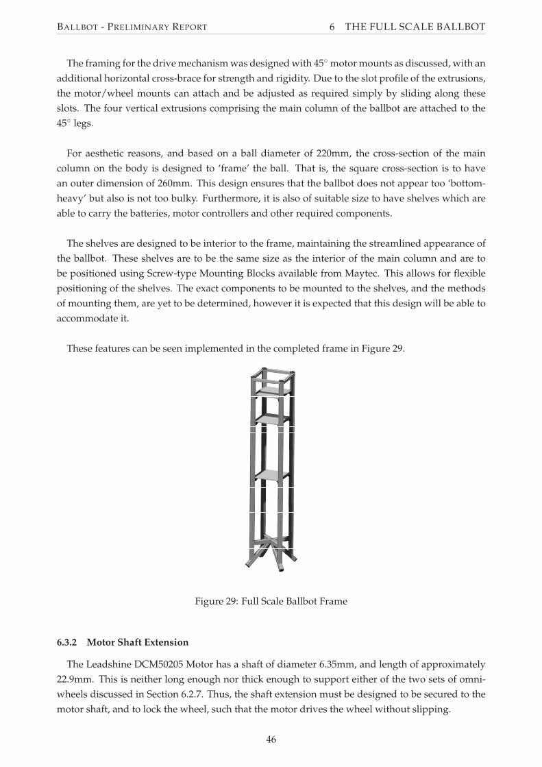
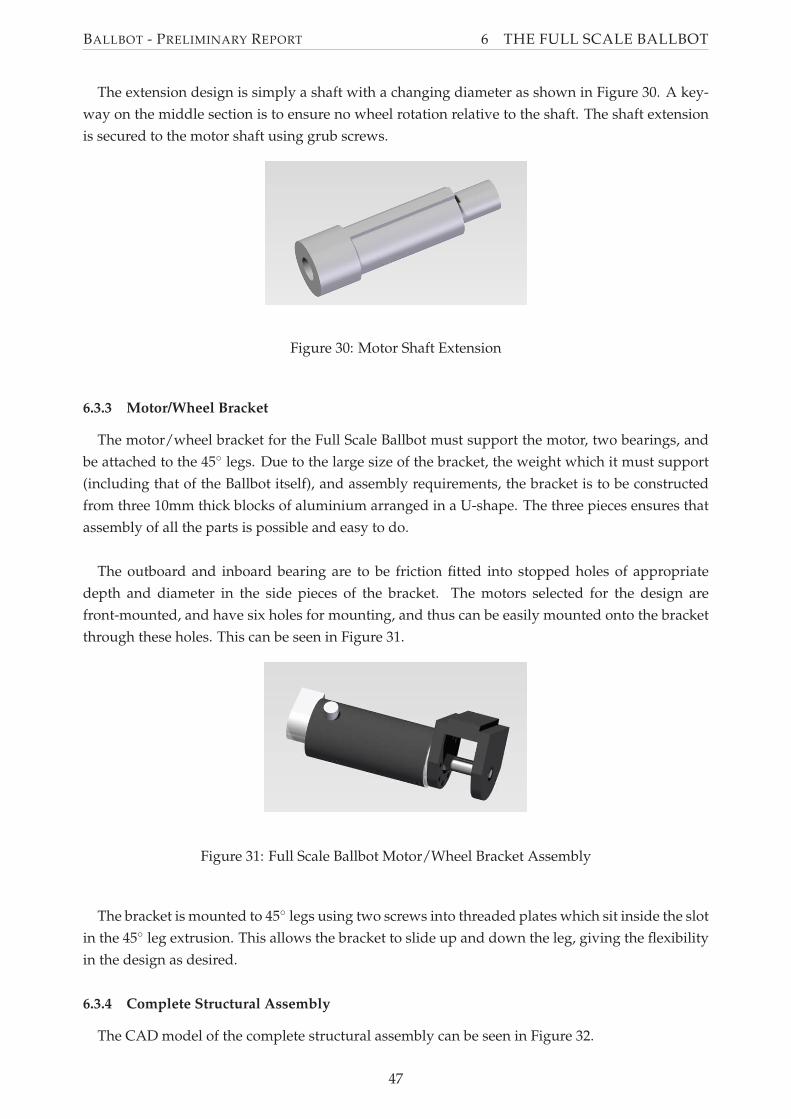
BALLBOT - PRELIMINARY REPORT 6 THE FULL SCALE BALLBOT
6 The Full Scale Ballbot
The design of the Full Scale Ballbot primarily involved developing a design which replicates
the functionality of the Lego Ballbot. In addition to this the design is governed by simplicity and
aesthetics. The simplicity of the design is essential for the successful construction in the limited
time frame available. The Full Scale Ballbot must also be aesthetically pleasing, due to its proposed
use as a promotional tool for the University of Adelaide. Further considerations were also given to
the cost of Ballbot, given the limited budget made available to the project from the Creativity and
Innovation Fund for Open Day 2009, and the Level IV Honours Project Budget.
The design was developed by first considering conceptual options and general design of the Full
Scale Ballbot. Based on this, the components required to achieve this design were selected. Finally,
the detailed design was produced with the knowledge of these components. This detailed design
included structural design of the frame and mounts for each of the components, as well as the
electrical design of interfaces between relevant components.
6.1 Conceptual Design
The concept design for the Full Scale Ballbot was based upon the Lego Ballbot. The Lego Ballbot
comprises of a frame housing components such as the controller and tilt sensors with the drive
mechanism at the base. The Full Scale Ballbot concept design is similar, consisting of a tall thin
column mounted above the drive mechanism. It is proposed that the column include adjustable
shelves onto which components can be mounted.
A drive mechanism and structure similar to that on the Lego Ballbot is proposed for the Full
Scale Ballbot - the ‘Inverse-Mouse Ball Drive.’ However, due to uncertainty in the project, it was
also considered desirable to allow for different ball sizes. Two main options were considered to
implement this, as shown in Figure 27.
(a) Concept 1 (b) Concept 2
Figure 27: Concepts for the Full Scale Drive Mechanism Frame (shown in one plane)
Concept 1 involves the construction of a square drive frame, with a larger base and a horizontal
cross. Motors and wheels can be mounted on adjustable vertical beams from the horizontal cross.
This design is highly flexible due to all dimensions being adjustable. The design, however, requires
a lot of framing and visually appears very bulky and bottom-heavy.
41
BALLBOT - PRELIMINARY REPORT 6 THE FULL SCALE BALLBOT
Concept 2 involves the drive mechanism supports being oriented at 45◦. The wheels are mounted
on this frame and as such can be adjusted along the axis of the frame, allowing for any ball size.
This concept requires less framework than concept 1, however is less adjustable as the drive wheels
can only be adjusted along one axis.
An additional advantage with both drive frame concepts is that they can be used to actuate the
ball at locations other than the side of the ball. This gives extra flexibility, and the facility to test
and utilise a drive mechanism which has not been constructed previously, such as that proposed
by Wu and Hwang (2008) as discussed in Section 2.2.1. Such a design would require the use
of omniwheels, however, does not require the simultaneous high and low friction coefficients as
required in the ‘Inverse-Mouse Ball Drive.’
The 45◦ drive mechanism frame was selected for the Full Scale Ballbot. This concept is simpler
to design and implement, and provides a more elegant design aesthetically.
6.2 Component Specification and Selection
The operational components required for the Full Scale Ballbot are the same as those required
for the Lego Ballbot - that is, a Controller, Tilt Sensors and Motors. Unlike the Lego Ballbot how-
ever, these components must be selected, as many options exist for each of these components. In
addition to this, other components such as the power supply, ball and wheels must also be selected.
6.2.1 Controller Hardware Selection
The requirements for the controller for the Full Scale ballbot are identical to those for the Lego
Ballbot. As such, the Lego NXT Mindstorms brick was selected to be used as the controller for
the Full Scale Ballbot, due to its suitability and the project team’s experience with the controller.
The NXT Mindstorms brick was deemed capable of controlling a ballbot system, as discussed in
Section 5.1, and thus suitable. The use of this controller also allows for easy modification of the
Lego Ballbot’s controller program for use in the Full Scale Ballbot.
6.2.2 Tilt Sensors
Due to the selection of the NXT Mindstorms Brick as the controller hardware, the simplest option
for the tilt sensors is to use the HiTechnic Gyroscopes and Accelerometer discussed in Section 4.1.
The use of these components ensures that minimal modifications will be required to the software
controller to estimate the tilt of the Ballbot. Furthermore, their performance has been tested on the
Lego Ballbot, and thus minimal further testing of these components is required.
The use of these Lego components, however, may introduce problems with mounting on the
frame, due to their lack of standard connections such as screw threads. However, this was consid-
ered insignificant due to the advantages gained using these components.
42
BALLBOT - PRELIMINARY REPORT 6 THE FULL SCALE BALLBOT
6.2.3 Motors
Selection of motors was based on two main criteria. The first was the desired performance
of the Full Scale Ballbot, and whether the motors could produce the required control authority
to achieve a stable ballbot. This was analysed via simulation, using motor characteristics from
available data sheets and approximate Ballbot physical characteristics. The second criteria was the
physical size and shape of the motors, and the ability to incorporate the motor in an aesthetically-
pleasing matter in the design. Other criteria included cost and availability. Motor selection was
limited to Brushed DC Servo motors, as these were considered preferable due to their similarity to
the Lego NXT Servo Motors, and their ease of control compared to brushless and other motors.
The motors selected for the Full Scale Ballbot are Leadshine DCM50205 DC brush servo motors.
These are 24V, 125W motors and provide a rated torque of 218.9 mNm at 3000rpm, and 1.59 Nm
at stall (see Appendix D). Simulation showed that these motors were capable of providing enough
torque for a stable ballbot, however it was apparent that more torque would result in better per-
formance. For this reason it was decided that all wheels would be driven, instead of having only
one driven wheel per plane, as in the Lego Ballbot. This effectively doubles the applied torque,
however, requires two additional motors. This option was considered preferable to using a gear-
box to increase torque, as the additional motor is cheaper than a gearbox and allows for a simpler
and less bulky mounting arrangement. The use of two motors in each plane also results in a more
balanced ballbot, both physically and aesthetically.
The selected motors are supplied with built in encoders. The encoders require a 5V supply and
produce a 500 count per turn quadrature encoder signal. The Lego NXT Servo motors produce an
equivalent signal, at 360 counts per turn, so it is believed that this encoder signal can be directly
used by the NXT brick with only minor alteration to the controller program and no additional
hardware.
6.2.4 Power Supply
A power supply is required on the Ballbot to power the motors and other electronics, including
the Lego NXT Mindstorms brick. The Full Scale Ballbot is a mobile robot, and thus it is desirable
that it use an on-board power source. Batteries are the simplest and cheapest sources of portable
energy, and thus are the power supplies to be used within this project. It was advised by supervisor
Associate Professor Ben Cazzolato that a Sealed Lead Acid (SLA) battery be used as the main
power source, so only this type of battery was considered for use. When selecting a battery, size,
weight, and capacity were the key selection criteria. It is required that the battery fit within the
centre column of the Ballbot, and that the weight not provide excessive load on the frame and
wheels. Thus the battery dimensions must not exceed approximately 200mm in any direction, and
total weight should not exceed 12kg. The battery must also be capable of providing the required
voltage and peak current for the motors.
The batteries selected for use in the Full Scale Ballbot are 12V SLA batteries available at Jaycar
Electronics. Two batteries will be used in series of provide the 24V required. These batteries pro-
vide high discharge capability and have deep discharge recovery characteristics. They also may
43
BALLBOT - PRELIMINARY REPORT 6 THE FULL SCALE BALLBOT
be used at any orientation, which is important due to possible oscillation in the ballbot body while
balancing or command tracking. A range of battery capacities is available, with larger capacity bat-
teries being larger and heavier. The particular battery selected is the 18Ah version, as this was the
largest capacity battery that meets the dimensional and weight requirements. The batteries have
dimensions 181x77x167 with a weight of 5.9kg, thus two adjacent batteries will have dimensions
181x154x167 with a total weight of 11.8kg, meeting the above specification.
6.2.5 Frame Material
The frame of the Full Scale Ballbot includes the drive mechanism and the column. As such it
is required that the frame material be light and strong enough to support the components in the
column. It was also desired that the frame material allow for ease of adjustability to provide the
features discussed in Section 6.1. Furthermore, the frame is perhaps the most important component
of the Ballbot in terms of aesthetics, and for this reason the material must be visually attractive.
Maytec Aluminium Extrusions were chosen to be used for the frame for a number of reasons.
Firstly, its neat appearance was deemed suitable for the Full Scale Ballbot Design. Secondly, it is a
product which is designed for frames, and thus can easily structurally accommodate the features
used on the Ballbot. Furthermore, its modular design and large variety of interacting components
allows for a robust and tailored design, which can be assembled with minimal use of the University
of Adelaide Mechanical Engineering Workshop. This was considered advantageous due to the
possibility of lengthy delays in the construction should the workshop be used.
6.2.6 Ball
The ball is used as the spherical driving wheel in the Full Scale Ballbot, and thus must fulfil
a number of criteria. First, the ball surface must have a high friction coefficient to eliminate slip
between the ball and the motor-driven actuating wheels, and the ball and the ground. Slip at these
interfaces will result in problems with control of the Full Scale Ballbot. Additionally, the ball must
be rigid, such that unnecessary damping is not introduced into the system. This will also reduce
the effectiveness of the controller, as the ball is modelled as being a rigid sphere in the derivation
of the dynamics (Section 3).
The Full Scale Ballbot has been designed to accommodate balls of varying sizes, due to the un-
certainty in the project. However, the nominal ball diameter for the design is 220mm. The ball used
for the Full Scale Ballbot is to be a bowling ball covered in rubber, in the form of ‘Plasti Dip.’ The
bowling ball provides a hard surface and thus the rigid property required. The thin layer of rub-
ber provides a high friction coefficient without significantly reducing this rigidity. This approach
was successfully used by Kumagai and Ochiai (2008) in the construction of the TGU Ballbot, which
required similar properties to that required by the Full Scale Ballbot design proposed in this report.
6.2.7 Wheels
Due to the nature of the proposed driving mechanism of the Full Scale Ballbot; standard, uni-
planar wheels would not be suitable for any arrangement other than the traditional, side-actuated,
44
BALLBOT - PRELIMINARY REPORT 6 THE FULL SCALE BALLBOT
inverse-mouse ball drive. Thus, omniwheels, which allow for slip in the axial direction, were
sought for the design. Fabrication of omniwheels was considered, however was deemed too ex-
pensive and labour-intensive to be feasible for this project.
Two suitable omniwheels were considered for this project (see Figure 28). One candidate was the
2570 Omni Wheel, which feature three rollers and must be used as a pair to provide full motion.
These were considered due to their aesthetically pleasing design. The second candidate was the
2052-3/8 Multiple Row Transwheel with Cat-Track Rollers. These were considered as the rollers
provide higher friction, which may result in better performance.
(a) 2570 Omni Wheels (Kornylak Corpora-tion, 2007)