LD17323 AIR HANDLING UNITS OPERATION AND MAINTENANCE New Release Form 102.20-OM2 (615) Issue Date: June 1, 2015 LD09624 OUTDOOR SOLUTION XT AHU INDOOR SOLUTION XT AHU YORK CUSTOM AHU LD13282 Renewal Parts With P/N contact Balt. Parts (800) 932-1701 Manufactured or specialty parts, contact Airside Technical Services (800) 545-7814
Transcript
LD17323
air handling units
OperatiOn and maintenance New Release Form 102.20-OM2 (615)
Issue Date: June 1, 2015
LD09624
OutdOOr sOlutiOn Xt ahuindOOr sOlutiOn Xt ahu
YOrk custOm ahu
LD13282
renewal parts
With p/n contact Balt. parts
(800) 932-1701
manufactured or specialty
parts, contact airside technical
services (800) 545-7814
JOHNSON CONTROLS2
FORM 102.20-OM2ISSUE DATE: 6/01/2015
This equipment is a relatively complicated apparatus. During rigging, installation, operation, maintenance, or service, individuals may be exposed to certain com-ponents or conditions including, but not limited to: heavy objects, refrigerants, materials under pressure, rotating components, and both high and low voltage. Each of these items has the potential, if misused or handled improperly, to cause bodily injury or death. It is the obligation and responsibility of rigging, instal-lation, and operating/service personnel to identify and recognize these inherent hazards, protect themselves, and proceed safely in completing their tasks. Failure to comply with any of these requirements could result in serious damage to the equipment and the property in
impOrtant!READ BEFORE PROCEEDING!
general saFetY guidelines
which it is situated, as well as severe personal injury or death to themselves and people at the site.
This document is intended for use by owner-authorized rigging, installation, and operating/service personnel. It is expected that these individuals possess independent training that will enable them to perform their assigned tasks properly and safely. It is essential that, prior to performing any task on this equipment, this individual shall have read and understood the on-prooduct labels, this document, and any referenced materials. This in-dividual shall also be familiar with and comply with all applicable industry and governmental standards and regulations pertaining to the task in question.
saFetY sYmBOlsThe following symbols are used in this document to alert the reader to specific situations:
Indicates a possible hazardous situation which will result in death or serious injury if proper care is not taken.
Indicates a potentially hazardous situa-tion which will result in possible injuries or damage to equipment if proper care is not taken.
Identifies a hazard which could lead to damage to the machine, damage to other equipment and/or environmental pollu-tion if proper care is not taken or instruc-tions and are not followed.
Highlights additional information useful to the technician in completing the work being performed properly.
External wiring, unless specified as an optional connection in the manufacturer’s product line, is not to be connected inside the control cabinet. Devices such as relays, switches, transducers and controls and any external wiring must not be installed inside the micro panel. All wiring must be in accor-dance with Johnson Controls’ published specifications and must be performed only by a qualified electrician. Johnson Controls will NOT be responsible for damage/problems resulting from improper connections to the controls or application of improper control signals. Failure to follow this warn-ing will void the manufacturer’s warranty and cause serious damage to property or personal injury.
JOHNSON CONTROLS 3
FORM 102.20-OM2 ISSUE DATE: 6/01/2015
changeaBilitY OF this dOcument
In complying with Johnson Controls’ policy for con-tinuous product improvement, the information con-tained in this document is subject to change without notice. Johnson Controls makes no commitment to update or provide current information automatically to the manual or product owner. Updated manuals, if applicable, can be obtained by contacting the nearest Johnson Controls Service office or accessing the John-son Controls QuickLIT website at http://cgproducts.johnsoncontrols.com.
It is the responsibility of rigging, installation, and op-erating/service personnel to verify the applicability of these documents to the equipment. If there is any ques-
tion regarding the applicability of these documents, rigging, lifting, and operating/service personnel should verify whether the equipment has been modified and if current literature is available from the owner of the equipment prior to performing any work on the unit.
change Bars
Revisions made to this document are indicated with a line along the left or right hand column in the area the revision was made. These revisions are to technical in-formation and any other changes in spelling, grammar or formatting are not included.
assOciated literature
manual descriptiOn FOrm numBer
Solution XT Air Handling Units Installation and Assembly 102.20-N1
York Custom Air Handling Units Installation and Assembly 102.20-N3
Steps to Protect New Equipment Warranty 102.20-CL1
Air Handling Units Start-up Checklist 100.00-CL1
Long-Term Storage Requirement - Field Preparation - Air Handling Units 50.20-NM3
Long-Term Storage Periodic Checklist and Logs - Air Handling Units 50.20-CL3
Limited Warranty 50.05-NM2
Electric Motor Warranty 50.05-NM2.2
Air Cooled Condensing Unit DX Coil Split System Applications and Piping Guidelines 50.40-ES3
supplY and return/eXhaust Fan OptiOnsA=NoneB=DWDI FC Fan without Motor ControllerC=DWDI FC Fan with Service Disconnect OnlyD=DWDI FC Fan with Motor StarterE=DWDI FC Fan with Variable Frequency Drive (VFD)F=DWDI AF Fan without Motor ControllerG=DWDI AF Fan with Service Disconnect OnlyH=DWDI AF Fan with Motor StarterJ=DWDI AF Fan with VFDK=SWSI PL Fan without Motor ControllerL=SWSI PL Fan with Service Disconnect onlyM=SWSI PL Fan with Motor StarterN=SWSI PL Fan with VFDP=SWSI PL Fan Direct Drive without Motor Controller Q=SWSI PL Fan Direct Drive with Service Disconnect OnlyR=SWSI PL Fan Direct Drivee with Motor StarterS=SWSI PL Fan Direct Drive with VFD
c
FactOrY mOunted end deVices0=No1=Yes
0 46m
mOtOr hOrsepOWersupplY and return/eXhaust Fan A=0B=1/2C=3/4D=1E=1 1/2F=2G=3H=5J=7 1/2K=10L=15M=20N=25P=60Q=40R=50S=60T=75U=100V=125
kVOltage cOde12=120-1-6017=200 or 208-3-6027=277-1-6028=230 or 240-3-6040=360-3-6044=440-3-5046=460-3-6050=380 or 415-3-5058=575-3-6063=220-3-50
a
designA=Original Unit Design
note: The terms skid and section have the same meaning in this document; Variable Speed Drive (VSD) and Variable Frequency Drive (VFD) do as well.
JOHNSON CONTROLS 5
FORM 102.20-OM2 ISSUE DATE: 6/01/2015
taBle OF cOntents
sectiOn 1 - general inFOrmatiOn and saFetY .......................................................................................13Introduction .....................................................................................................................................................13About This Manual..........................................................................................................................................13Warranty .........................................................................................................................................................13Responsibility For Safety ................................................................................................................................13
sectiOn 2 - start-up and OperatiOn ..........................................................................................................15Before Start-Up ..............................................................................................................................................15
Inspecting Fan Assembly ......................................................................................................................16Inspecting Belts and Sheaves ...............................................................................................................17Checking Isolators .................................................................................................................................17Start-Up .................................................................................................................................................19Checking Operation of Fans ..................................................................................................................19Checking Operation of Dampers ...........................................................................................................19Energize Fan Motors .............................................................................................................................29Variable Frequency Drive (VFD) ..........................................................................................................29Check Doors And Latches .....................................................................................................................29Energy Recovery Wheel ........................................................................................................................29Indirect Fired Gas Heat Start Up ..........................................................................................................34Starting the Electric Heater ...................................................................................................................46
Operation ........................................................................................................................................................50Test And Balance ...................................................................................................................................50Setting Limits .........................................................................................................................................50Checking Motors, Belts and Sheaves ...................................................................................................51P-Cone® ................................................................................................................................................51
sectiOn 3 - maintenance ................................................................................................................................53General Requirements ...................................................................................................................................53Inspect Parts ..................................................................................................................................................54
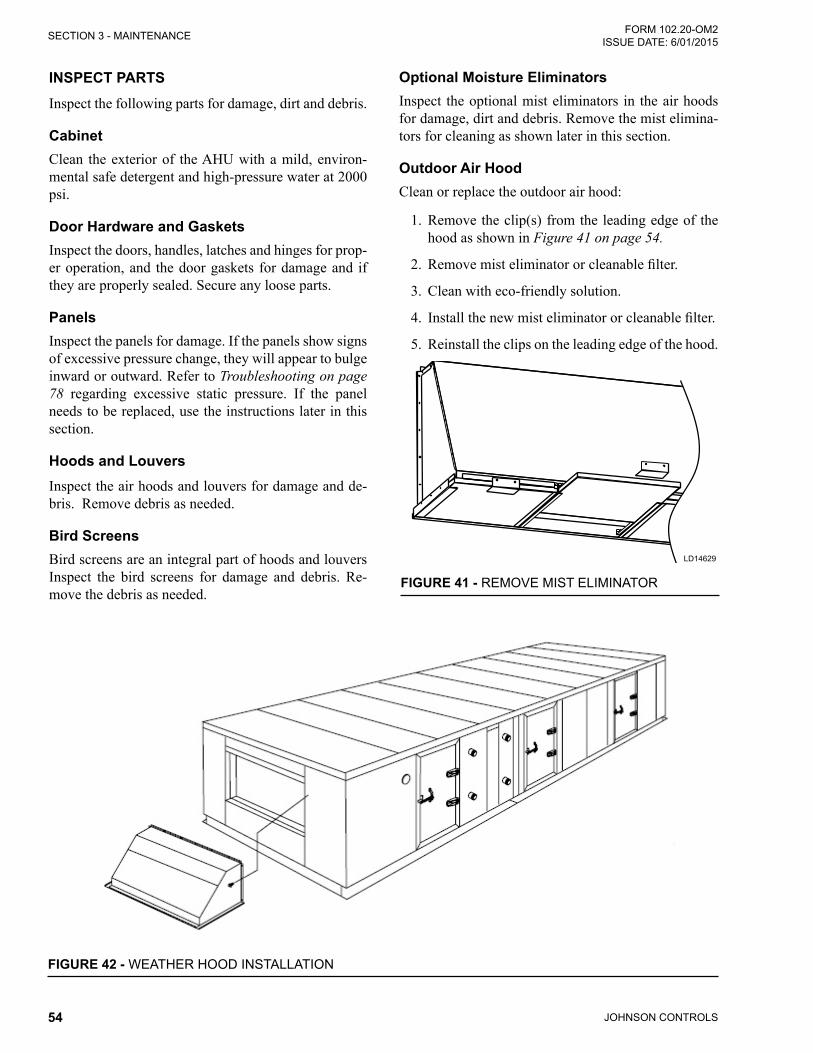
Cabinet ..................................................................................................................................................54Door Hardware and Gaskets .................................................................................................................54Panels ...................................................................................................................................................54Hoods and Louvers ...............................................................................................................................54Bird Screens ..........................................................................................................................................54Optional Moisture Eliminators ...............................................................................................................54Outdoor Air Hood ...................................................................................................................................54
Fan Segment (Supply, Return or Exhaust) ....................................................................................................55Removing the Fan .................................................................................................................................55Checking the Fan ..................................................................................................................................55
Operating Adjustable Motor Base ..................................................................................................................55Standard ................................................................................................................................................55Checking Belt Tension ...........................................................................................................................57
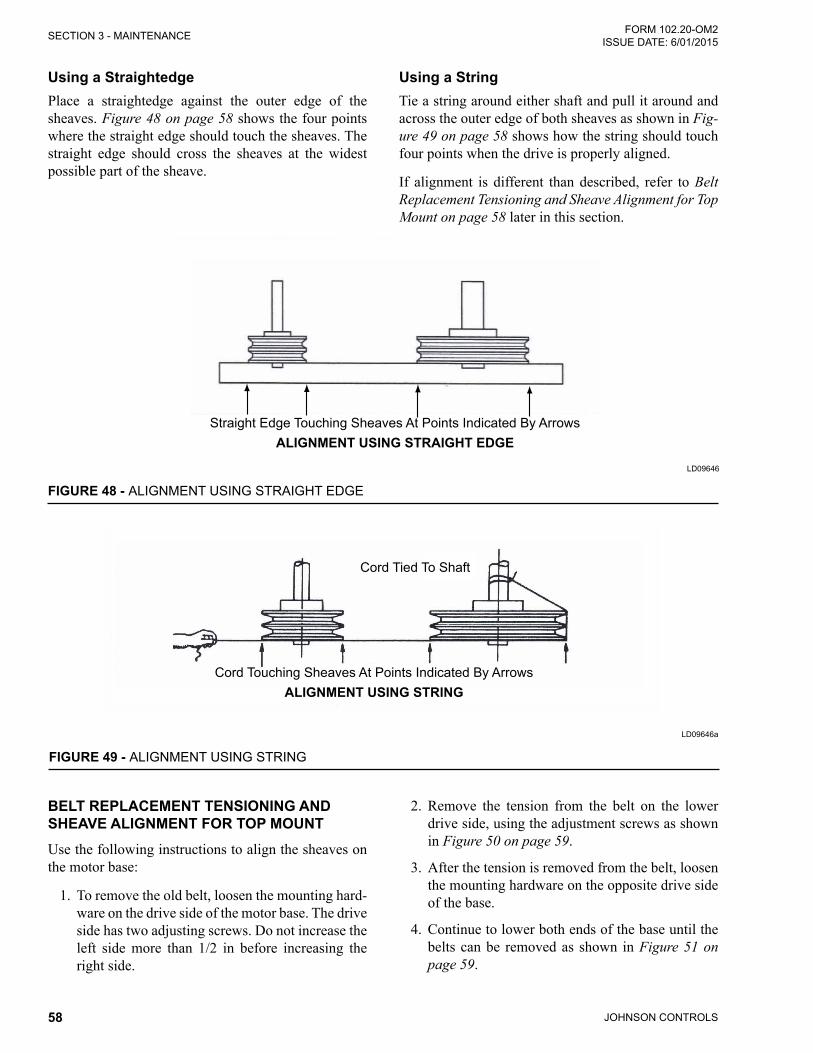
Aligning Sheaves ...........................................................................................................................................57Using a Straightedge .............................................................................................................................58Using a String ........................................................................................................................................58
Belt Replacement Tensioning and Sheave Alignment for Top Mount .............................................................58Lubrication ......................................................................................................................................................60
Fan Bearing Lubrication ........................................................................................................................61
JOHNSON CONTROLS6
FORM 102.20-OM2ISSUE DATE: 6/01/2015
taBle OF cOntents (cOnt'd)
Checking Condition of Extended Lubrication Lines ...............................................................................61Recommended Lubricant for Bearings ..................................................................................................61Proper Interval and Quantity .................................................................................................................61
Lubricating the Fan Segment and Motor ........................................................................................................62Checking Condition of Mounting Hardware, Adjustable Motor Base and Motor ....................................63Checking Electrical Connections ...........................................................................................................63Keep Motor Bearing Lubricated .............................................................................................................63
UVC Emitter Lamps ........................................................................................................................................64Three Types of Lamps ...........................................................................................................................65
Maintaining and Replacing Filter Segments ..................................................................................................65Replacing the Filters ..............................................................................................................................66
Coil Segment Cleaning ...................................................................................................................................66Tools, Equipment and Materials ...........................................................................................................66Cleaning Procedure ...............................................................................................................................67
Condensate Drain Pan, Trap and Line Cleaning ...........................................................................................67Tools, Equipment and Materials ............................................................................................................67Schedule and Conditions ......................................................................................................................67Cleaning Procedure ..............................................................................................................................68Coil Freeze Protection ...........................................................................................................................68
Energy Recovery Wheel .................................................................................................................................68Airxchange® ..................................................................................................................................................68
Tools and Materials ..............................................................................................................................68Cleaning the Wheel ...............................................................................................................................69Adjusting Air Seals ................................................................................................................................69Inspect Wheel Drive Components .........................................................................................................70
NovelAire® Technologies ................................................................................................................................70Cleaning the Wheel ...............................................................................................................................70Adjusting Air Seals ................................................................................................................................71Inspect Wheel Drive Components .........................................................................................................71How to Measure, Assemble and Install .................................................................................................71
Thermotech® ..................................................................................................................................................72Cleaning the Wheel ...............................................................................................................................72Adjusting Air Seals ................................................................................................................................72Inspect Wheel Drive Components .........................................................................................................73
Innergy Tech® ................................................................................................................................................73Cleaning the Wheel ...............................................................................................................................73Adjusting Air Seals ................................................................................................................................73Inspect Wheel Drive Components .........................................................................................................74
P-Cone® .........................................................................................................................................................75Maintenance of P-Cone® ......................................................................................................................75
JOHNSON CONTROLS 7
FORM 102.20-OM2 ISSUE DATE: 6/01/2015
sectiOn 4 - serVice and repair ....................................................................................................................77Service Tools and Equipment .........................................................................................................................77Service Information ........................................................................................................................................78Troubleshooting ..............................................................................................................................................78Pitot Tube .......................................................................................................................................................78Inclined Manometer ........................................................................................................................................79Filter Gauge ....................................................................................................................................................79U-Tube Manometer ........................................................................................................................................79Duct Pressures ...............................................................................................................................................80
appendiX a – start-up checklist ..............................................................................................................107
appendiX B – lOng-term stOrage ............................................................................................................ 111Temperature ................................................................................................................................................. 116
taBle OF cOntents (cOnt'd)
JOHNSON CONTROLS8
FORM 102.20-OM2ISSUE DATE: 6/01/2015
list OF Figures
Figure 1 - Solution XT Seismic Isolator ................................................................................................................15Figure 2 - Example of a Solution XT Termination Chart .......................................................................................16Figure 3 - Fan and Motor Isolator Support Frame................................................................................................17Figure 4 - Spring Isolator......................................................................................................................................17Figure 5 - Spring Isolator Set-Up .........................................................................................................................18Figure 6 - Counterbalance Locked into Place for Shipping ..................................................................................19Figure 7 - Counterbalance Unlocked for Start-Up ................................................................................................19Figure 8 - Front of a 2X2 Fan Array .....................................................................................................................20Figure 9 - Back of a 2X2 Fan Array ......................................................................................................................20Figure 10 - Front of a 1X2 Fan Array ...................................................................................................................20Figure 11 - High And Low Connections for an In Fan Air Monitoring System ......................................................23Figure 12 - High And Low Connections and Associated Tubing for Fan Mounted Air Monitoring System ...........24Figure 13 - Port Locations for Fan Mounted Air Monitoring System ....................................................................24Figure 14 - Ductwork Inlet Requirements.............................................................................................................25Figure 15 - Ductwork Radius................................................................................................................................25Figure 16 - 25% Sensing Option ..........................................................................................................................25Figure 17 - 25%/75% Sensing Option ..................................................................................................................25Figure 18 - 25%/75% Sensing Option ..................................................................................................................26Figure 19 - Example of Sweep Balance Results Label On Fan Housing .............................................................29Figure 20 - Metal Spacers on Solution XT Doors .................................................................................................29Figure 21 - Vertical Wheel for Indoor AHU ...........................................................................................................29Figure 22 - Horizontal Wheel for Outdoor AHU ....................................................................................................30Figure 23 - Energy Recovery Wheel - Pulley Side ...............................................................................................31Figure 24 - Segment Retainer ..............................................................................................................................32Figure 25 - Diameter Seal Adjustment .................................................................................................................32Figure 26 - Purge Angle Detail .............................................................................................................................33Figure 27 - Purge Angle Detail .............................................................................................................................34Figure 28 - Gas Furnace Condensate Drain Trap ................................................................................................36Figure 29 - Open Fuse Disconnects ....................................................................................................................37Figure 30 - Set Id Fan Damper ............................................................................................................................37Figure 31 - Check Main Gas Supply Pressure .....................................................................................................37Figure 32 - Draft Over Fire Test Port ....................................................................................................................38Figure 33 - Flue Combustion Temperature and Efficiency Test Port- ID Blower ..................................................38Figure 34 - Damper Actuator ................................................................................................................................38Figure 35 - Example Solution XT Gas Furnace Fuel Venting System .................................................................43Figure 36 - Typical Wiring Diagram ......................................................................................................................44Figure 37 - Minimum Air Velocity Required for Safe Operation............................................................................48Figure 38 - Pressure Probe Direction...................................................................................................................49Figure 39 - Air Flow Switch Connections .............................................................................................................49Figure 40 - V-Belt Drive Kit Label .........................................................................................................................51Figure 41 - Remove Mist Eliminator .....................................................................................................................54Figure 42 - Weather Hood Installation .................................................................................................................54Figure 43 - Typical Drive Kit Data Tag ..................................................................................................................55Figure 44 - Solution XT Adjustable Motor Base ...................................................................................................55Figure 45 - Solution XT Adjustable Motor Base (Top Mount) ...............................................................................56Figure 46 - Belt Tensioning ..................................................................................................................................57Figure 47 - Belt Tensioning Gauge .......................................................................................................................57
JOHNSON CONTROLS 9
FORM 102.20-OM2 ISSUE DATE: 6/01/2015
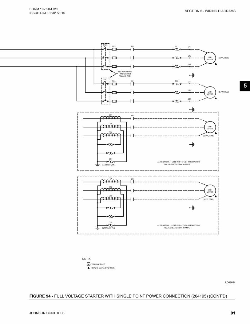
Figure 48 - Alignment Using Straight Edge ..........................................................................................................58Figure 49 - Alignment Using String ......................................................................................................................58Figure 50 - Sheave Angular Misalignment ...........................................................................................................59Figure 51 - Motor Base Lowered..........................................................................................................................59Figure 52 - Sheave Angular Alignment.................................................................................................................59Figure 53 - Sheave Angular Misalignment ...........................................................................................................60Figure 54 - Sealed Bearing ..................................................................................................................................60Figure 55 - Bearing with Set Screw Type Locking Device ...................................................................................60Figure 56 - Bearing with Eccentric Cam...............................................................................................................60Figure 57 - Split Bearing (Assembled) .................................................................................................................61Figure 58 - Optional Lubrication Lines .................................................................................................................61Figure 59 - Open Drip Proof (ODP) Motor ...........................................................................................................63Figure 60 - Totally Enclosed Fan Cooled (TEFC) Motor ......................................................................................63Figure 61 - UV Lamps ..........................................................................................................................................65Figure 62 - Installing V-Mod Lamp .......................................................................................................................65Figure 63 - Installing V-Ray and V-Max Grid Lamps ............................................................................................65Figure 64 - V-Max Grid Lamps .............................................................................................................................65Figure 65 - Typical Filter Types ............................................................................................................................65Figure 66 - Installing Angle Filters ........................................................................................................................66Figure 67 - Installing Side Load Filters.................................................................................................................66Figure 68 - Rinse Segments ................................................................................................................................69Figure 69 - Diameter Seal Adjustment .................................................................................................................69Figure 70 - Airxchange® Energy Recovery Wheel With Bearing Support Beam Side ........................................70Figure 71 - How to Measure.................................................................................................................................71Figure 72 - Disassembly ......................................................................................................................................71Figure 73 - Assembly ...........................................................................................................................................71Figure 74 - Installation..........................................................................................................................................72Figure 75 - Loosen Screws Before Adjusting Seals .............................................................................................72Figure 76 - ERW Seal Locations ..........................................................................................................................73Figure 77 - Airloop™ Labyrinth Seal Adjustment .................................................................................................74Figure 78 - Plenum Fan Tap Location and Connection Illustration ......................................................................75Figure 79 - Maintenance Requirements ...............................................................................................................76Figure 80 - Construction of Pitot Tube .................................................................................................................78Figure 81 - Pitot Tube...........................................................................................................................................78Figure 84 - Magnehelic Filter Guage....................................................................................................................79Figure 82 - Inclined Manometer ...........................................................................................................................79Figure 83 - Minihelic Filter Gauge ........................................................................................................................79Figure 85 - U-Tube Manometers ..........................................................................................................................80Figure 86 - Slack Tube Manometer ......................................................................................................................80Figure 87 - Static Pressure Air System ................................................................................................................81Figure 88 - Inserting Cap Screws.........................................................................................................................82Figure 89 - Standard Mounting ............................................................................................................................82Figure 90 - Reverse Mounting..............................................................................................................................83Figure 91 - Adjustable Pitch Sheave (JVS) ..........................................................................................................84Figure 92 - Adjustable Pitch Sheave (FHP) .........................................................................................................85Figure 93 - Full Voltage Starter ............................................................................................................................88Figure 94 - Full Voltage Starter With Single Point Power Connection (204195) ..................................................90
list OF Figures (cOnt'd)
JOHNSON CONTROLS10
FORM 102.20-OM2ISSUE DATE: 6/01/2015
list OF Figures (cOnt'd)
Figure 95 - Outside Air Damper Kit (Relay Installation) .......................................................................................92Figure 96 - Solution XT Termination Chart Inside Enclosure Door ......................................................................93Figure 97 - Typical FPC Wiring Diagram ..............................................................................................................94Figure 98 - Transformer Enclosure Wiring Detail (Shown Open) .........................................................................96Figure 99 - Transformer Wiring Diagram..............................................................................................................97Figure 100 - UV Control Panel Wiring (8 amps)...................................................................................................99Figure 101 - UV Control Panel Wiring ( greater than 8 amps) ...........................................................................100Figure 102 - Gas Heat, Single Phase, 1500Va Transformer Wiring Diagram ....................................................102Figure 103 - Gas Heat, Three Phase, 1000Va Transformer Wiring Diagram .....................................................103Figure 104 - Gas Heat, Three Phase, 500Va Transformer Wiring Diagram .......................................................104Figure 105 - Typical Wiring Diagram for Electric Heat Control Type Vermier ....................................................105Figure 106 - Typical Wiring Diagram for Control Type Full SCR ........................................................................106
JOHNSON CONTROLS 11
FORM 102.20-OM2 ISSUE DATE: 6/01/2015
list OF taBles
taBle 1 - Torque for Tightening Set Screws ..........................................................................................................16taBle 2 - Air Measuring Device Connections ........................................................................................................21taBle 3 - Indoor Unit Example ..............................................................................................................................27taBle 4 - Outdoor Unit Example ...........................................................................................................................28taBle 5 - Gas Heat Segment Model Number Nomenclature ................................................................................39taBle 6 - Natural Gas Pressure Requirements (Inches Wc) ................................................................................40taBle 7 - Natural Gas Pressure Requirements (Inches Wc) ................................................................................41taBle 8 - Inlet Size (NPT) .....................................................................................................................................42taBle 9 - Burner Temperature Rise ......................................................................................................................45taBle 10 - Maximum Current for 75°C Copper Wire .............................................................................................47taBle 11 - Minimum / Maintenance Requirements According to ASHRAE ...........................................................53taBle 12 - Fan Bearing Re-Lubrication Intervals for Ball Bearing Pillow Blocks ..................................................62taBle 13 - Fan Bearing Lubrication Intervals for Spherical Roller Bearing Solid Pillow Blocks ............................62taBle 14 - Fan Bearing Lubrication Intervals for Spherical Roller Bearing Split Pillow Blocks .............................62taBle 15 - Fan Bearing Lubrication Intervals for Dodge ISN Bearings .................................................................62taBle 16 - Motor Bearing Lubrication Intervals .....................................................................................................64taBle 17 - Motor Bearing Service Conditions .......................................................................................................64taBle 18 - Motor Bearing Lubrication Interval Multiplier .......................................................................................64taBle 19 - Cap Screw Torque Values ..................................................................................................................83taBle 20 - Set Screw Torque Values.....................................................................................................................83taBle 21 - SI Metric Conversion ......................................................................................................................... 116
Fan motorEnergizing at Start-up 28Inspection and Maintenance 62Bearing Lubrication 63FanCleaning 55Inspection 55gas heatControl Wiring 44Filters (aF, FF, rF)Types 65Maintenance And Replacement 65Inserting into Side Load Filter Tracks 66motorsCheck Amperage after Air Balancing 51
sheavesReplacing after Air Balancing 51Alignment 57
start-up Start-Up Checklist 19test and BalanceAir Balance 50Dynamic Balance 50Variable Frequency drive (VFd)Set-Up of Non Factory Mounted VFD 29
JOHNSON CONTROLS 13
FORM 102.20-OM2 ISSUE DATE: 6/01/2015
1
intrOductiOn
The YORK air handling unit (AHU) is manufactured to the highest design and construction standards to en-sure high performance, reliability and adaptability to all types of air handling installations.
aBOut this manual
This manual and any other document supplied with the AHU are the property of Johnson Controls, which re-serves all rights. This manual may not be reproduced, in whole or in part, without prior written authorization from an authorized Johnson Controls representative.
In addition, this manual:
• Includes suggested best working practices and procedures, which are issued for guidance only, and they do not take precedence over the above stated individual responsibility and/or local safety regulations.
• Contains all the information required for correct installation and commissioning of the AHU, to-gether with operating and maintenance instruc-tions.
• Should be read thoroughly before attempting to operate or service the AHU.
• Contains detailed procedures, including installa-tion, commissioning and maintenance tasks that must only be performed by suitably trained and qualifiedpersonnel.
The manufacturer will not be liable for any injury or damage caused by incorrect installation, commission-ing, operation, or maintenance resulting from a failure to follow the procedures and instructions detailed in the manual.
WarrantY
Johnson Controls warrants YORK AHUs in accor-dance with the limited warranty engineered systems equipment procedure. Refer to the Air Side Limited Warranty and Limited Warranty (Form 50.05-NM2) for more information.
Johnson Controls warrants all equipment and materi-als against defects in workmanship and materials for a period of 18 months from the date of shipment or 12 months from the date of start-up, whichever comes first, unless labor or extended warranty has been pur-chased as part of the contract.
The warranty is limited to parts only replacement and shipping of any faulty part or subassembly, which has failed due to defects in workmanship and materials. All claims must be supported by evidence that the failure has occurred within the warranty period, and that the AHU was operated within the designed parameters specified.
All warranty claims must specify the AHU model, se-rial number, order number, and run hours/starts. Model and serial number information is printed on the AHU identification plate.
The AHU warranty will be void if any modification to the AHU is carried out without prior written approval from Johnson Controls. For warranty purposes, the fol-lowing conditions must be satisfied:
• Only genuine YORK approved spare parts must be used.
• All of the scheduled maintenance operations de-tailed in this manual must be performed at the specified timesby suitably trained andqualifiedpersonnel.
• Failure to satisfy any of these conditions will au-tomatically void the warranty. Refer to Air Side Limited Warranty and Limited Warranty (Form 50.05-NM2) for details.
respOnsiBilitY FOr saFetY
Every care has been taken in the design and manufac-ture of the AHU to ensure compliance with the safety requirements. However, the individual operating or working on any equipment is primarily responsible for:
• Personal safety, safety of other personnel, and the equipment.
• Correct utilization of the equipment in accordance with the procedures detailed in this manual.
sectiOn 1 - general inFOrmatiOn and saFetY
JOHNSON CONTROLS14
FORM 102.20-OM2ISSUE DATE: 6/01/2015SECTION 1 - GENERAL INFORMATION AND SAFETY
THIS PAGE INTENTIONALLY LEFT BLANK.
JOHNSON CONTROLS 15
FORM 102.20-OM2 ISSUE DATE: 6/01/2015
2
sectiOn 2 - start-up and OperatiOn
• All shipping splits are sealed and secured properly.
• For outdoor AHUs, Pipe chase floor is sealed at penetrations.
• All shipping bolts and other materials were removed.
• Visually inspect the roof curb for tight seal around the outdoor AHU.
• Do not remove the functional bolts from the seis-mic isolators as shown in Figure 1 on page 15.
Figure 1 - SOLUTION XT SEISMIC ISOLATORLD09636a
• Ensure the damper linkage is tight and is in the correct power off position.
• If the return air dampers are closed, loosen the actuator or crank arm on the jackshaft, open the dampers, and retighten the actuator or crank arm.
• Verify the following controls installation are com-plete:
• Contractor Furnished Controls - Controls contractor is responsible for safe and proper control of the AHU.
• Factory Furnished Controls - Refer to the Factory Engineered Controls/Factory Pack-aged Controls (FEC/FPC).
• Make sure the termination chart is attached to the inside of the control enclosure door as shown in Figure 2 on page 16.
Never use silicone caulk/sealant or caulk/sealant containing silicone in or on any air handling equipment.
BeFOre start-up
Perform a general inspection. Identify and perform the appropriate the lock out/tag out and safety rules. Re-fer to the AHU Start-up Checklist, (Form 100.00.CL1) provided with the information package shipped with the AHU.
For more information about the steps below, refer to the Solution XT - Installation and Assembly Manual (Form 102.20-N1) and Custom AHU - Installation and Assembly Manual (Form 102.20-N3). For an AHU equipped with a Variable Frequency Drive (VFD), re-fer to the specific VFD literature for additional start-up requirements.
• Check for damage to the AHU's interior and ex-terior.
• Ensure the terminal screws and wiring connec-tions are secure in the control, electric and air modulator panels.
• Verify that the:
• Equipment was received as ordered.
• AHU was installed on flat and level surface and with proper clearances.
• Air hoods are installed properly.
• Condensate drains are properly trapped.
• All wiring and tubing connections are com-plete at
shipping splits.
• All field piping connections are completed.
• All shipped loose parts are installed.
• All ductwork is complete and available for full airflow.
• Installer removed all dirt, debris, hardware, mold, etc. from interior of the AHU and its ducts.
• Filter gauge is set to zero.
JOHNSON CONTROLS16
FORM 102.20-OM2ISSUE DATE: 6/01/2015SECTION 2 - START-UP AND OPERATION
Figure 2 - EXAMPLE OF A SOLUTION XT TERMINATION CHARTLD16563b
inspecting Fan assemblyUse the following instructions to inspect the fan assem-bly.
1. When the AHU is removed from long term stor-age, purge the moisture-laden bearing grease, and replenish the AHU with fresh grease, according to the lubrication label.
2. Meg the motor to verify that the resistance is at a satisfactory level, compared to the value recorded prior to storage.
3. Check the torque for bearings and locking collars as shown in Table 1 on page 16.
4. Verify that the fan wheel is properly aligned, is tight on the shaft, and moves freely.
5. Make sure the fan bearings are properly lubricat-ed. Refer to SECTION 3 - MAINTENANCE in this manual for more information.
JOHNSON CONTROLS 17
SECTION 2 - START-UP AND OPERATIONFORM 102.20-OM2 ISSUE DATE: 6/01/2015
2
6. On Solution units, verify that the tie down bolts are removed from the four corners of the fan base assembly as shown in Figure 3 on page 17. For small AHUs, the tie down bolts may only be ap-plied to three corners of the fan base since one corner is not accessible.
Do not remove the shipping bolts if there are no springs.
Figure 3 - FAN AND MOTOR ISOLATOR SUPPORT FRAME
LD09638
Tie Down Bolts
inspecting Belts and sheaves1. Verify that the sheaves are properly aligned and
tight on the shaft. Improper sheave alignment and belt tension are potential causes of excessive noise and vibration, and shortened belt and bear-ing life. Refer to SECTION 3 - MAINTENANCEin this manual for more information.
2. Check the belt tension. If not familiar with the process, refer to SECTION 3 - MAINTENANCE in this manual. It is normal for belts to loosen af-ter start-up. The new belts will run in or take a set by seating slightly deeper into the grooves of the sheaves. Recheck the tension after one day, and three days.
3. Make sure the motor mounting bolts and adjust-able motor base bolts are tight.
checking isolators
Solution XT IsolatorsCheck the fan base isolators and thrust restraints for proper adjustment.
• Standard fan isolation consists of spring isolators as shown in Figure 4 on page 17 mounted un-der the internal fan assembly.
• For thrust restraint adjustment procedures, if ap-plicable, refer to the service manual.
• Prepare the fan isolators for operation, using the following instructions:
1. After removing the tie down bolts from the internal fan assembly, check the blower/mo-tor frame for the correct height, and that the frame is level.
2. To adjust the isolators as shown in Figure 4 on page 17,
a. Loosen the cap screws on top of the ad-justment bolt.
b. Turn the adjusting bolt.
c. Check the operational height and level of the frame. Repeat this procedure until the height and frame are level.
d. Tighten the cap screws. Refer to the ser-vice manual for additional instructions.
• Verify the fan is aligned with the AHU discharge.
• Readjust the isolators as necessary.
Figure 4 - SPRING ISOLATORLD09637
JOHNSON CONTROLS18
FORM 102.20-OM2ISSUE DATE: 6/01/2015SECTION 2 - START-UP AND OPERATION
Place tubes on studs, and place shoulder washer (shoul-der up) on studs. Place one nut on each stud and tighten it on shoulder washer.
Place remaining nuts on studs, and tighten to lower nut to lock in place.
Custom AHU Isolators
Fan hold-down/spring isolator set-upAll fans are internally spring isolated and will be bolt-ed down for unit shipping. After unit is in place, assem-bled and leveled, Fan Hold-Down can be disassembled by removing two nuts and one washer from each side. Remove tubes from wire and discard wire.
STUDSTUD
TUBE
TUBE
1/2”
NUTS
NUTS
SHOULDERWASHER
SHOULDERWASHER
OPERATING POSITIONSIDE VIEW
EXPANDED ASSEMBLYVIEW
WIRE
TUBE
STUDNUTS
SHOULDERWASHER
SHIPPING POSITIONSIDE VIEW
P-STYLE PLUG FAN
7.25 OPERATING HGT 8.1875 OPERATING HGT
FAN (PLENUM SHOWN)
SHIPPED POSITIONSHIPPING BLOCK
SHIPPING BOLT
BUY-OUT ISOLATORS
1. Remove the 7/8 nut as shown in the operating position view.
2. Loosen the 7/8 jam nut between the isolator housing and the fan base support angle until the desired level is achieved.
3. Repeat step two until all isolators are set at the proper elevation and the fan base is level.
Figure 5 - SPRING ISOLATOR SET-UP
JOHNSON CONTROLS 19
SECTION 2 - START-UP AND OPERATIONFORM 102.20-OM2 ISSUE DATE: 6/01/2015
2
start-upDo not be operate this AHU until after start-up is completed as outlined in these instructions. Do not allow the AHU to run on unreliable temporary power, which could turn the AHU on/off periodically or rapidly, and to protect it from irregular voltages and surges.
It is recommended that the start-up technician use the AHU Start-up Checklist (Form 100.00-CL1), included with the AHU, and record the gathered information in the appropriate fields. If there are questions, refer to Table 11 on page 53 for inspection requirements.
Install the provided or temporary filter media prior to start-up to adequately protect the components in the air stream and duct system.
If the AHU is equipped with an energy recovery wheel, rotate the wheel when the AHU is in service to prevent clogging.
checking Operation of FansCheck of the operation of the fans by:
1. Verifying the correct voltage, phase and cycles.
2. Energizing the power to the AHU disconnect switch.
3. Energizing the fanmotor(s), briefly (bump)andcheck for correct fan rotation.
If the fan rotation is incorrect:
1. On three-phase equipment, reverse any two motor leads at the load side of the last starter component.
2. On single-phase equipment, follow the wiring diagram on the motor housing or on the inside of the motor terminal box.
3. Recheck for correct fan rotation.
checking Operation of dampersMost units are shipped with dampers in closed position. Release and adjustment is to be done by field technician only
Make sure the AHU will not operate with all dampers closed.
Linkage design and/or damper linkage is optional. Air-flow control dampers may be operated with pneumatic or electric actuator/controllers.
Prior to occupancy, test the ventilation system to en-sure that the outdoor air dampers operate properly in accordance with the system design.
Back Draft Dampers for Dual Fans and Fan Arrays The counterbalance is locked into place for shipping as shown in Figure 6 on page 19. Before startup, the counterbalance will have to be released. To do this, loosen the set screws and slide the counterbalance off the end of the shaft. Flip the counterbalance and slide it back on the shaft. Rotate the counterbalance above the damper as shown in Figure 7 on page 19, and then tighten the set screws. The counterbalance should be free to rotate.
Figure 6 - COUNTERBALANCE LOCKED INTO PLACE FOR SHIPPING
LD17103
Figure 7 - COUNTERBALANCE UNLOCKED FOR START-UP
LD17198
JOHNSON CONTROLS20
FORM 102.20-OM2ISSUE DATE: 6/01/2015SECTION 2 - START-UP AND OPERATION
Airflow Control DampersMany combinations of damper sizes are available to control the flow. Mixing the return and outside air in the AHU's air inlet section may be supplied as follows:
• 100% outside air, 100% return air.
• 100% outside air, 0% return air.
• 0% outside air, 100% return air.
• Economizer section - 100% outside air, 100% re-turn air, 100% exhaust air or mixed air.
Check the dampers, actuators, controls and linkage prior to applying power to the operators, to make sure nothing will obstruct the operation of the dampers.
Do not overdrive the damper actuators because this may damage the dampers.
Exception: Actuators with over drive preset option.
Return air dampers may be closed for shipping. Loosen the actuator or crank arm on the jackshaft, open the dampers, and retighten the actuator or crank arm. The field is responsible for adjustments.
SF 2 105 592.00 N/A SF 2 182 1673.00 N/ASF 2 122 842.00 N/A SF 2 200 1942.00 N/ASF 2 135 963.00 N/A SF 2 222 2454.00 N/ASF 2 150 1147.00 N/A SF 2 245 3010.00 N/A
taBle 2 - AIR MEASURING DEVICE CONNECTIONS (CONT'D)
air measuring at the Fan inlets• COMETER is a probe attached to the fan bearing
support on Comefri Forward Curve fans from size 7 x 7 up to 18 x 18. The probe is located on the outboard side of the housed fan assembly. The probe is piped to the negative (-) port of a factory mounted transducer on the fan wall. The positive (+) port is left open to the fan section. Wiring is not provided to the transducer unless factory packaged controls were selected.
• PIEZORING(PIEZOMETER) is afittingor se-riesoffittingsintheinletcone(s)ofhousedfanslarger than 18 x 18 and all sizes of Plenum fans that are combined into a single connection piped to the negative (-) port of a factory mounted trans-ducer on the fan wall. The positive (+) port is left open to the fan section. Wiring is not provided to the transducer unless factory packaged controls were selected.
The fan manufacturer does not recom-mend placement of the flow measuring probes inside the fan inlet cone in the path of airflow. These devices create disturbances and unpredictable perfor-mance losses.
Figure 11 - HIGH AND LOW CONNECTIONS FOR AN IN FAN AIR MONITORING SYSTEM
LD17231
JOHNSON CONTROLS24
FORM 102.20-OM2ISSUE DATE: 6/01/2015SECTION 2 - START-UP AND OPERATION
Figure 12 - HIGH AND LOW CONNECTIONS AND ASSOCIATED TUBING FOR FAN MOUNTED AIR MONITORING SYSTEM
LD17232
Figure 13 - PORT LOCATIONS FOR FAN MOUNT-ED AIR MONITORING SYSTEM
LD17233
High PortLow Port
air measuring at unit Outside air inlets• AMS-60 used on indoor air handlers usually mea-
sure outside air. This can be provided with one or two pairs of positive (+ or High) and negative (- or Low) pressure tube connections. Connect (+) & (-) respectively to the (+) & (-) ports of the transducer(s). Wiring & transducer are not pro-vided unless factory packaged controls were se-lected.
• EAML used on outdoor air handlers usually to measure outside air. This can be provided with one or two pairs of positive (+ or High) and nega-tive (- or Low) pressure tube connections. Con-nect (+) & (-) respectively to the (+) & (-) ports of the transducer(s). Wiring & transducer are not provided unless factory packaged controls were selected.
ams-60 damper
GeneralThe YORK AMS-60 is an airflow monitoring device which combines the functions of control damper and airflow measurement station into one assembly. It is ideally suited for factory installation in air handling units. The YORK AMS-60 is tested to AMCA Stan-dard 611-95 and qualifies to bear the AMCA Ratings Seal for Airflow Measurement Performance.
Damper OperationThe AMS-60 airflow monitoring damper design incor-porates a low leakage control damper with stationary, vertical air monitoring blades and air straightening sec-tion into one assembly. The control damper utilized for modulating airflow is the ultra-low leak Ruskin CD-60 with its standard blade and jamb seals used for low leakage. Strategically placed stationary and vertical airflow sensing blades measure the airstream velocity pressure. Air tubing/piping connections are provided to connect the sensing blades to an optional factory-mounted transducer. The transducer converts the ve-locity pressure from the sensing blades to an electri-cal output signal for the Building Automation System (BAS). The output signal corresponds directly to flow through the damper. The BAS compares this signal to the design CFM setpoint as determined by the particu-lar mode of operation of the HVAC system. In normal operation, this setpoint corresponds to the minimum outside air ventilation required by the system design to meet ASHRAE Standard 62. Based on the differ-ence between the actual CFM reading and the desired setpoint, the BAS would send a signal to the optional, factory-mounted control damper Actuator to position the damper blades as necessary to ensure that the actual outside airflow meets the desired level.
No Calibration RequiredThe AMS-60 airflow monitoring damper is factory cal-ibrated. Calibration is not required at the jobsite.
JOHNSON CONTROLS 25
SECTION 2 - START-UP AND OPERATIONFORM 102.20-OM2 ISSUE DATE: 6/01/2015
2
Ductwork Inlet RequirementsWhen connecting the ductwork to a mixing box with an AMS-60 damper, a minimum of one (1) equivalent duct diameter of straight duct is required before enter-ing the AMS-60 damper.
1 equivalent duct diameter = d
D
W
HMixing Box
Figure 14 - DUCTWORK INLET REQUIREMENTS
LD17215
If one equivalent duct diameter cannot be achieved during installation, the rectangular elbow may be sub-stituted with a radius elbow. The outside radius must have a R/W ratio of 0.75 or more.
Mixing BoxR
W
Figure 15 - DUCTWORK RADIUS
LD17243
Damper Linkage ArrangementsThe AMS-60 mixing box will ship with independent return air and outside air damper actuators if selected in the MB or FM segments.
Louver/Damper CombinationOutdoor AHU economizer and mixing box sections will utilize an integral rain resistant, airflow sensing louver/damper combination with operation and set-up similar to the AMS-60. The indoor and outdoor AHU designs have the same possible damper configurations.
Damper ConfigurationsThere are 3 possible damper configurations, 25% Sens-ing option (Min./Max.), 25%/75% Sensing option, and 100% Sensing option.
• 25% Sensing Option (Min./Max.)
Figure 16 - 25% SENSING OPTION
LD17244
The 25% Sensing (Min./Max.) option arrangement is a dual damper design and used for measuring the mini-mum outside air requirement. In this arrangement, the 25% damper would be for monitoring airflow through the first 25% down to 3.75% nominal flow and the 75% damper would have a separate actuator and used for economizer control only.
This option would be the best low cost option for areas in which economizer cycles are not often seen, such as the southeast, and are required to constantly operate in at the minimum outside air position.
• 25/75% Sensing Option
Figure 17 - 25%/75% SENSING OPTION
LD17245
JOHNSON CONTROLS26
FORM 102.20-OM2ISSUE DATE: 6/01/2015SECTION 2 - START-UP AND OPERATION
The 25/75% Sensing option arrangement is similar to the 25% Sensing (Min./Max.) option, but allows you to measure airflow throughout the economizer cycle also. In this arrangement, the 25% damper would be for monitoring nominal airflow through the first 25% down to 3.75% and the 75% damper would be for mon-itoring the remaining 75%.
• 100% Sensing Option
The 100% sensing arrangement is a single damper de-sign used to measure airflow throughout the full range of the outside air damper down to 15% of nominal air-flow.
Figure 18 - 25%/75% SENSING OPTION
LD17246
The 100% sensing option is the lowest cost option, but should not be utilized when minimum airflow to be sensed falls below 15% nominal flow. The 25% Sens-ing (Min./Max.) and 100% Sensing option arrange-ments will be the most prevalent.
The 100% Sensing arrangement with the outside and return air dampers tied to a common actuator, will usually be the most common configuration and cost-effective solution. However, areas in which economiz-er cycles are not often seen and operate primarily in minimum outside air position, the 25% Sensing option should be the preferred option for lowest airflow moni-toring and a cost-effective solution.
In each of the available configurations, the minimum airflow across the sensing portion of the airflow moni-toring station is 300 FPM for the indoor AHU and 345 FPM for the outdoor AHU.
Factory Mounted Control OptionThe AMS-60 airflow monitoring station may be or-dered with or without Factory-mounted End Devices. The Optional End Devices must be selected through the YorkWorks program and consist of the following:
• Modulating, Spring Return Actuator(s)
• Low Pressure Transducer(s)
YorkWorks will provide all wiring schematics.
Jumper SelectionsWhen selected, the AMS-60 factory provided trans-ducers technically provides six (6) jumper selections which allow you to select the appropriate range for your application. However, only three (3) are appli-cable to the AMS-60 function. The jumper selections are as follows: 0-1", 0-.5", and 0-.25". These are field adjustable. To determine the correct jumper setting for your application, refer to the equation and examples on Table 3 on page 27 for indoor AHUs and Table 4 on page 28 for outdoor AHUs.
Input PowerA 24VAC power supply can be wired into the supply voltage terminals on the Factory-mounted Actuator and Transducer.
CFM Input Signal to Damper Actuator
2-10VDC (BELIMO)
0-10 VDC (JOHNSON CONTOLS)
CFM Output Signal from Transducer
0-10VDC
Sequence Of OperationA 0-10 VDC or 2-10VDC control signal is sent to the AMS 60 damper actuator from the Building Automa-tion System (BAS). The BAS maintains the required cfm by modulating the actuator on the control damper. The BAS receives a 0-10 VDC signal back from the transducer, confirming the cfm supplied. Upon loss of power, the AMS-60 actuator returns to a closed posi-tion.
JOHNSON CONTROLS 27
SECTION 2 - START-UP AND OPERATIONFORM 102.20-OM2 ISSUE DATE: 6/01/2015
2
End Devices Requirements*It is necessary for an independent contractor to provide controls capable of sending 0-10 VDC or a 2-10VDC signal to the actuator and receiving a 0-10VDC signal back from the transducer. A 24VAC power source must be provided.
* This paragraph only applies if the actuator and trans-ducer are YORK supplied. Any controls provided by "others" are the contractor's responsibility.
AHU Airflow Station SpecificationsFurnish and install, at locations indicated on plans and/or schedules, an air monitoring station integral with outside air control damper, stationary airflow sensing-device, and air straightening section. The integral air monitoring station shall incorporate pressure sensing ports built into the sensing device and shall control the minimum amount of outside air as recommended by ASHRAE 62-2001. The airflow monitoring station must be tested in accordance with AMCA Standard 611-95 in an AMCA registered laboratory. The air-
flow monitoring station must bear the AMCA Certified Ratings Seal for Airflow Measurement Performance. If airflow station is internally mounted inside air han-dling unit and incorporates a control damper, the con-trol damper must comply with leakage rates of damper specification.
If ASHRAE 90.1 is referenced, also includeIf airflow station is internally mounted inside air han-dling unit and incorporates a control damper, the control damper must comply with leakage rates per ASHRAE 90.1-1999. All damper leakage rates must be provided in submittal data on a CFM/FT2 at 1" w.g. basis.
AMS-60 (Indoor AHU)Use the following equation to determine the correct jumper setting for your application:
CFM=(FREE AREA*Ka)*Pams (1/m), where Ka = 3213
Pams = Range of transmitter, and (l/m) = 0.54.
taBle 3 - INDOOR UNIT EXAMPLE
unit name Fan design FlOW (cFm)
ams sensing (%)
ams O.a. setpOint
(cFm)
ams-60 sensing damper dimensiOns 100% sensing
ams sensing
area (sQ. Ft.)
"a" dim. (in.) "B" dim. (in.)
AHU-01 21370 25 7000 22.5 32.75 5.1
range: 0.0 tO +0.25min maX
0 0.25
Recommended operating range is 345-2,000 FPM. Op-eration outside these parameters is not recommended.
Locating and Installing ActuatorsJohnson Controls standard actuators are direct coupled on the damper jackshaft. Refer to the instructions in the Solution XT Air Handling Units - Installation and Assembly Manual (Form 102.20-N1) and York Custom Air Handling Units - Installation and Assembly Man-ual (Form 102.20-N3) to install the Johnson Controls actuators.
Damper Blade OrientationUse the following instructions to orient the damper blades.
return air and mixing dampers 1. Position the blades so that they will be open after
the actuator is installed, which will be the damp-ers spring return position.
2. Note whether the damper shaft is rotated clock-wise or counterclockwise.
Outside air and exhaust air dampers1. Position the damper blades so that they will be
closed with the power off, which will be the damp-ers spring return position. Note if the damper shaft is rotated clockwise or counterclockwise.
2. With the actuator shaft clamp tightened to the damper jackshaft, and the damper shaft complete-ly rotated to its proper position, manually operate the actuator to its fully actuated position, using the crank arm provided with the actuator.
3. Release the spring to allow the damper to go back to its original position, which will verify the ac-tuators spring rotation and stroke.
4. Set the damper actuators rotation selector switch to the proper rotation required to actuate the damper. The damper actuator will always be op-posite the spring return rotation.
energize Fan motorsUse the following instructions to energize the fan mo-tors:
1. Observe the fan(s) for smooth operation.
2. Check the motor nameplate for the full load amp (FLA) rating.
3. Check the current draw of each leg of each motor.
JOHNSON CONTROLS 29
SECTION 2 - START-UP AND OPERATIONFORM 102.20-OM2 ISSUE DATE: 6/01/2015
2
Variable Frequency drive (VFd) Johnson Controls air modulators are, unless otherwise selected, provided with start-up service. See forms 100.41-NO1 and 100.42-NO1.
The VFD controlling the speed of the AHU fan(s) needs to be set up properly so the fan does not run at resonant frequencies. This is true whether the VFD is field or factory mounted. An option is available when ordering the AHU to select Inverter Drive Balance (Sweep Bal-ance). When the option is selected, the factory provides a document or label attached to the fan assembly that lists any values that exceed the peak to peak tolerance. See Figure 19 below. These values are referred to as Skip Frequencies (Jump or Lockout Frequencies). The technician performing start up of the VFD is to enter these values in the VFD programming according to the manufacturer’s instructions. This step will prevent continuous operation at the resonant frequencies listed on the label. If the option was not selected on the AHU order, it is the customer’s responsibility to have the In-verter Drive Balance (Sweep Balance) performed and enter any detected Skip Frequencies (Jump or Lockout Frequencies) in the VFD program. This should be done during start up.
Failure to properly set up the VFD before applying power to the motor will void the fan and motor warranty.
Figure 19 - EXAMPLE OF SWEEP BALANCE RESULTS LABEL ON FAN HOUSING
LD16564
check doors and latchesRefer to the service manual for adjusting and replacing the doors.
Solution XT doors are shipped with metal shipping spacers glued onto the edges of each door. They are located on three edges of each door (top, latch side & bottom) (Figure 20 on page 29). The spacers should be left in place until the AHU is placed in its final loca-tion and multiple skid AHUs are fully assembled. After AHU installation use a channel lock pliers or a screw-driver to remove the spacers. Do not damage the metal door panel. Slight impressions left on the door gasket by the spacers will rebound in approximately a week.
Figure 20 - METAL SPACERS ON SOLUTION XT DOORS
LD16574
energy recovery Wheel
Configuring the AHUIndoor AHUs - All indoor AHUs will accommodate vertical energy recovery wheel segments in a tiered configurationasshowninFigure 21 on page 29.Outdoor AHUs - All outdoor AHUs will accommo-date horizontal energy recovery wheel segments in a low-profile,singleAHUarrangementasshowninFig-ure 22 on page 30.
Keep hands away from rotating wheel! Contact with the rotating wheel can cause physical injury.
Figure 21 - VERTICAL WHEEL FOR INDOOR AHULD16566
Filter
Return Air
Supply Fan
Mixing Box
Cooling Coil
Energy Wheel
Heating Coil
Exhaust Fan
Filter/Mixing Box
Outside Air
JOHNSON CONTROLS30
FORM 102.20-OM2ISSUE DATE: 6/01/2015SECTION 2 - START-UP AND OPERATION
Figure 22 - HORIZONTAL WHEEL FOR OUTDOOR AHU
LD09641a
Elevation View
Plan (Top) View
Supply Fan
Supply Fan
Cooling Coil
Cooling Coil
Heating Coil
Heating Coil
Filter
Filter
Acc
ess
Acc
ess Engery
Wheel
Engery Wheel
O/A Damper Return Air
Return Air
R/A Damper
O/A Bypass
E/A Bypass
O/A Damper
Exhaust Fan
Exhaust Fan
When the AHU is operating normally or temporarily, the energy recovery wheel must rotate to prevent clogging.
Many energy recovery wheels are sus-ceptible to damage if the AHU reaches a maximum temperature, which can occur if the heating valve remains open when the AHU is off. The maximum temperatures across energy recovery wheels:
1. Thermotech - 140°F
2. Innergy Tech - 122°F
3. NovelAire® Technologies - 200°F
4. Airxchange® - 170°F
JOHNSON CONTROLS 31
SECTION 2 - START-UP AND OPERATIONFORM 102.20-OM2 ISSUE DATE: 6/01/2015
2
Airxchange®
start-up procedure1. With the power off, turn the wheel clockwise
(as viewed from the pulley side) to verify that the wheel turns freely through a 360° rotation as shown in Figure 23 on page 31.
2. Beforeapplyingpowertothedrivemotor,confirmthat the wheel segments are fully engaged in the wheel frame, and the segment retainers are com-pletely fastened as shown in Figure 23 on page 31 and Figure 24 on page 32.
3. With hands and objects away from the moving parts, activate theAHU, and confirm thewheelrotation. The wheel rotates clockwise from the pulley side.
4. Ifthewheelhasdifficultystarting,turnthepoweroff, and inspect it for excessive interference be-tween the wheel surface and each one of the four diameter seals. To correct, loosen the diameter seal adjusting screws and back adjustable diam-eter seals away from surface of the wheel. Apply powertoconfirmthewheelisfreetorotate,thenreadjust and tighten hub and diameter seals as shown in Figure 25 on page 32.
Figure 23 - ENERGY RECOVERY WHEEL - PULLEY SIDE
LD09642
Ball Bearings (2)
Bearing Support Beam - Motor Side
Drive Motor
Drive PulleyBelt
Bearing Support Beam - Pulley Side
Bearing Access Cover (2)
Diameter Seal Adjusting Screws
Removable Energy Transfer Segment (8)
Wheel Rotation
JOHNSON CONTROLS32
FORM 102.20-OM2ISSUE DATE: 6/01/2015SECTION 2 - START-UP AND OPERATION
1
2
Figure 24 - SEGMENT RETAINER
LD09643
Segment Retainer Catch
Rotate Away From Wheel Rim
Push Toward Center
Wheel Rim Center Of Wheel
Spoke
Figure 25 - DIAMETER SEAL ADJUSTMENT
LD09644
To Remove
Rotation
Diameter Seal
To Adjust
Feeler Gauge
Diameter Seal Adjusting Screws
Innergy tech®
start-up procedure1. Make sure all bearing bolts and set screws are
tight. A special seal lacquer is factory applied. This is a visual aid that will warn you if the pillow block bolts or the bearings set screws have loos-ened over time or during transport. A seal without cracks is the indication that bolts and screws have not loosened.
2. Be sure to use all lifting eye bolts when position-ing energy recovery wheel into unit or ducting location, and that weight is evenly distributed. If the eye bolts need to be removed, bolts or plugs should replace them in order to avoid any air leak-age from these holes (required with top, bottom and side galvanized plate option only).
3. Grease both pillow block bearings on the wheel, using a NLGI grade 2 consistency, mineral oil lithium or lithium complex base grease.
4. Before start-up, make sure the wheel turns by hand and does not bind. All contact between the sealsandmediashouldbeverifiedandthesealsadjusted if needed.
5. Visually inspect the wheel to ensure it is centered and does not tilt. If there is any indication of a problem, call Innergy tech at 1-800-203-9015.
6. Does the power supply match the supply required by the electrical equipment? If not, the electrical equipment or the power supply must be changed. Thewheelidentificationtaglocatedneartheelec-trical input gives the proper voltage to use.
Check the drive motor by bump starting it. Check the wheel rotation to ensure it is turning in the correct di-rection. If the wheel is turning backward, reverse the motor rotation.
JOHNSON CONTROLS 33
SECTION 2 - START-UP AND OPERATIONFORM 102.20-OM2 ISSUE DATE: 6/01/2015
2
Thermotech®
start-up procedure1. Remove the belts from the motor sheave and ro-
tate the wheel a minimum of one full Revolution. The seals are non-contact. If the wheel does not rotate freely it may be due to the wheel being in contact with the seal. If the wheel cannot be turned by hand contact Thermotech.
For TC sizes 14-82. To remove the belt, an idler pulley will need to be loosened.
2. The side seals should also be checked for clear-ance to insure nothing has moved in shipping. If the wheel is in contact with the aluminum encas-ing the side seals, the wheel will need to be re-centered in the casing. This is done by loosening the bearing bolts and by using the bearing adjust-ing bolts. Re-center the wheel insuring proper side seal clearance. Re-tighten bearing bolts as follows: 3/8 inch = 35 ft lbs., 1/2 inch = 45 ft. lbs., 3/4 inch = 100 ft lbs.
3. Check to insure sheave/bushing is not rubbing on the gear box.
4. At this point the wheel should rotate freely with no drag or rubbing, with the exception of the riv-ets at the hub cover. A slight rub here is accept-able. Proper wheel rotation technique:
Rotate wheel by applying pressure to the rim not the media. Care should be taken not to damage the media face.
5. The seals are set at the factory and should not re-quire adjustment. If the seals are rubbing on the media face, due to installation or other factors, the seals will need to be adjusted. First, rotate the wheel one full revolution and determine where the wheel media face is rubbing on the seal. Work-ing on one seal quadrant at a time, loosen the seal tek screws. Then, move the seal away from the wheel surface until no more rubbing is noticed. A typical large diameterwheelwill have a flat-ness variation of 1/16” from the high to the low point of the wheel surface. If the seals are adjusted correctly, the seal gap will vary that much as the wheel turns, but it should never be touching the wheel surface.
6. If the unit is supplied with an adjustable purge, determine the proper purge angle from the order-ingcodeontheunitnameplateorthespecificdatafor your project. Insure proper purge angle set-ting is correct by visual inspection. The minimum purge angle is 1 degree. There are 10 adjustment points in one degree increments.
Purge Adjustment: TF Series Wheels
The purge angle can be adjusted with each purge set-ting hole equal to one degree. The bolts that position the purge angle are located on the backside of the purge and are not visible. First loosen bolt 2 and 3. Then re-move the bolt 1. The whole purge section is then mov-able to a new location. Re-install bolt 1 in the new hole location and re-tighten all the bolts.
Figure 26 - PURGE ANGLE DETAILLD17222
Purge Adjustment: TC Series Wheels
The purge angle can be adjusted with each purge set-ting hole equal to one degree. Bolt number 1 positions the purge angle and is located on the front side of the purge. Bolt number 2 is the pivot point and is located on the inside of the frame and is not visible. First loos-en bolt 2. Then remove bolt 1. The purge wiper section is then movable to a new location. Re-install bolt 1 in the new hole location and re-tighten all the bolts.
Purge angle detail showing bolt locations on front side of purge. The purge wiper bolt 2 pivot point is slotted so as the purge wiper is adjusted it can be moved so that the outer edge of the seal is always in contact with the main rotor seal.
JOHNSON CONTROLS34
FORM 102.20-OM2ISSUE DATE: 6/01/2015SECTION 2 - START-UP AND OPERATION
Figure 27 - PURGE ANGLE DETAILLD17223
7. Grease bearings using Dow Corning Molykote BR2-plus Lithium based high pressure grease. Applythegreasetothefittingwhileturningwheeluntil a slight amount of grease is purged. Remove visible grease residue from the bearing. The bear-ingsarefilledwithgreasepriortoshipment.Thisstep may be required if the units have been idle on the job site for more than 6 months. Put belts back on pulley.
8. If the unit is provided with a VFD, verify the mo-tor is wired for the correct voltage provided by the VFD.
NovelAire® Technologies
start-up procedure1. Does the rotor rotate freely by hand? If not, re-
check the seal to determine whether or not it is binding and if so adjust seals following the in-structions below.
2. Is the motor rotation correct? This can be checked by detaching the belts from the drive sheave and bumping the motor. The sheave should be rotat-ing in the direction such that the belt will result in rotation per the exterior markings. If not, rewire the motor.
4. Are thebeltsoncorrectlyandsufficiently tight?Belt length is set by the manufacturer. Consult NovelAire® Technologies if the belt appears too loose.
5. Is the VFD programmed to control the unit and to prevent frost formation? If not, follow the instruc-tions in the manual accompanying the VFD and/or consult NovelAire® Technologies.
indirect Fired gas heat start up For your safety, this product requires a check, test, and start-up adjustment by a qualified HVAC technician. Do not use for temporary heat prior to start-up.
This gas burner has been carefully inspected and tested at the factory; however, different conditions at the job site, including controls that have been added at the time of installation, require careful testing and final adjust-ment for satisfactory operation. The Burner Test Re-port/Factory Specification Sheet in each AHU shows the general data recorded during the operation and safety tests at the factory. This data should be used as a general guide; with final data recorded on the start-up form. Do not exceed 550°F flue temperature at the ID fan inlet. Do not exceed 200°F supply air temperature.
Review the burner control literature, including wiring, piping, cut sheets and drawings before attempting to start this gas heating equipment.
All factory test start up burner specifications are locat-ed on a laminated Burner Test Report/Factory Specifi-cation Sheet located on the inside of the control panel door. Each gas burner has been test run and inspected at the factory. Adjustments to the component settings are typically not required. However, measurements of the system parameters should be taken and compared to the measurements recorded on the burner test report, to ensure safe and reliable operation.
Use the following instructions to start an indirect fired gas heat system on an AHU.
Identify the Gas Burner TypeTwo types of indirect fired gas burners are used on the AHUs: Powerflame and the Eclipse series.
The Powerflame series offers a turndown (modulating ratio) of 3:1 or 10:1. The Powerflame is easily identifi-able by the motorized gas valve with external linkage connecting the air dampers on the burner air inlet.
The Eclipse series uses an air/gas ratio regulator with no external linkage, and has a turndown range of 10:1 to 25:1 (sometimes greater). A visible external plastic tube is used to transmit gas pressure from the burner to the regulator. No external linkage is used.
JOHNSON CONTROLS 35
SECTION 2 - START-UP AND OPERATIONFORM 102.20-OM2 ISSUE DATE: 6/01/2015
2
Both burners utilize a combustion air blower, and use an exhaust blower, called an induced draft (ID) blower, which keeps the combustion chamber at a slight nega-tive pressure. Verification of this negative pressure and other system parameters is part of a proper start up pro-cedure.
Preliminary CoordinationContact the contractor/customer who requested start-up, and do the following:
• Ensure the AHU and system is capable of design airflowforgasheatstart-up.
• Ensure reliable power is available.
• Verify the following:
• Verify the AHU was properly started up.
• Gas lines are purged of air to the equipment valve.
• Controls are complete.
• Flue (stack) is correctly installed, if parts were shipped loose.
Recommended Tools• Electrical Multimeter with Amprobe.
• Heating AHU Installation and Operation Instruc-tions, which are provided with every heating AHU for technical information and troubleshooting.
• Magnehelic Gauge 0-25 in WC, Dwyer Series 2000 or Model 1227 Dual Range Manometer for checkingpressureoverfire(draft).
• Control Signal Generator, 0 to 20 mA (Altek-234 or 334A) - For 2 to 10 VDC signal add 500 ohms in series with signal generator.
• Magnehelic Gauge 0-15 in WC and 0 to 3 lb (Dw-yer series-2000) or Monometer (Dwyer- 1227) Duel Range Monometer for checking supply gas pressure and manifold gas or pilot gas pressure.
• Honeywell - S7800A Test Module for use on (Honeywell-7800) Series Relay Module, which is available through Airside Parts
• Flue Gas Analyzer (CO2 and O2)
• Stack Thermometer (0°F-1000°F approx.)
• Digital Manometer (replaces Magnehelic Gauge): Digital Manometer, Cat. #475-1 FM-AVSeries: 475-1 Mark III, Range: 0 to 19.99 In. W.C.from Dwyer Instruments, Inc.
Pre-Start-Up ChecklistCondensate trap must be installed prior to start-up by the installing contractor.
Refer to Figure 28 on page 36 for installing the gas furnace condensate drain trap.
Use the following information to check the AHU be-fore starting it:
• Verify the AHU was properly started up, and that airflowisatthedesignmaximumfortheheatingcycle. Refer to the air balance report.
• Set the bypass damper, if provided.
• Airflow proving switch formain supply fan in-stalled and operational.
• Check with the control technician: two-minute post-purge programmed in AHU controller. Upon call for unit stop, burner cycles off, then AHU fan cycles off two minutes later.
JOHNSON CONTROLS36
FORM 102.20-OM2ISSUE DATE: 6/01/2015SECTION 2 - START-UP AND OPERATION
1
1
2
43
1
2
3
4
LD12912
Figure 28 - GAS FURNACE CONDENSATE DRAIN TRAP
Flow
BurnerAssy
Field Installed Condensate Drain Piping - By OthersClean Out
Checking the Burner1. Open the fuse disconnects before working on
burner as shown in Figure 29 on page 37.
2. Check all wire terminations for tightness.
3. Check that the incoming voltage(s) are correct. Compare the measured voltages to the burner mo-tor and ID motor nameplates, and the burner test report. Reset the fuse disconnects.
4. Check for the correct rotation of the three phase burner and ID motors.
5. Verify that the contractor purged the new gas lines of air up to the manual valve on the gas train.
6. Open the valves, which were closed for shipping. Check that all manual valves operate without leaks.
7. Theflue(stack)damperislocatedatthedischargeof the ID blower and was closed for shipping. Re-lease the locking mechanism, and set the damper to match the position indicated by the scribed markings. Lock it in place as shown in Figure 30 on page 37.
8. Inspect the condensate drain trap to see that it is large enough.
9. Measure the gas supply pressure coming into the gas train as shown in Figure 31 on page 37. Gas pressure can be greater than shown on the burner test report, but it must be between the min./max. values listed in Table 7 on page 41.
10. Visually check that the high temperature safe-ty limit is set for a 200-230°F range. The limit switch is typically mounted behind the burner control panel.
11. Connect a 0-15 inch gas pressure gauge or other suitable instrument to the gas manifold port. The gas pressure will be measured when running. Re-fer to Step 4 in Starting the Burner.
12. On Powerflame burners, the test port is down-stream of the main regulator, typically on a stan-dardteefittinginthemaingasline.
13. On Eclipse burners, the test port is located on the backside of the burner below the spark igniter. A small valve is provided at this test port.
JOHNSON CONTROLS 37
SECTION 2 - START-UP AND OPERATIONFORM 102.20-OM2 ISSUE DATE: 6/01/2015
2
14. Connect a manometer or other suitable device to the heat exchanger draft port located on the side of the AHU near the burner. The expected draft should read slightly negative about -0.03 inches WC. The draft port is typically made of 3/4 in steel pipe and may be plugged. Remove plug and add a small stop valve and a nipple for a rubber tube.
15. Install the Honeywell S7800 Test Module, if available.
16. Connect the signal generator (0-20mA) to ter-minals in place of modulation control signal (for 2-10VDCsignaladda500Ωresistorinseries).
17. Visually check that the flue (stack) is secureand connected properly. Typical connections are shown at the end of these instructions.
18. The burner panel's on/off switch should be off.
19. The system is now ready for start up.
Figure 29 - OPEN FUSE DISCONNECTSLD12903
BURNER CONTROL
PANEL
Figure 30 - SET ID FAN DAMPERLD12910
Figure 31 - CHECK MAIN GAS SUPPLY PRESSURE
LD12905
Starting the Burner1. Prior to starting the burner, the technician must
verify the incoming gas pressure. A minimum pressure is listed on the burner test report. The maximum pressure is listed as well.
2. Open the manual gas valves on gas supply and pilot line.
3. Initiate a call for heat or use jumper to create a call for heat.
4. Turn the burner panel on/off switch to on.
5. Once there is a call for heat, a 30-second pre-purge period is initiated to remove any gases from the heat exchanger. The burner will go through a second purge before ignition.
6. The burner will automatically go to low fire atstart-up.After proof of lowfire, the burnerwillmodulateuptohighfire,whichmaytake15sec-onds for a Powerflame burner, and 90-180 sec-onds for the Eclipse burner. After the burner oper-ates at High Fire use the manometer connected to the Heat Exchanger Draft Port as shown in Figure 32 on page 38, observe the reading. A pressure of-0.03inchesWCisexpectedfordraftoverfire.Readings may differ slightly from those shown on the Burner Test Report.
7. For valid readings before making any adjust-ments,allowtheburnertofireatleast20minutesto allow the heat exchanger to rise to the operating temperature.
8. Observe the gas manifold pressure and compare to the data on the Burner Test Report under both highandlowfireconditions.
JOHNSON CONTROLS38
FORM 102.20-OM2ISSUE DATE: 6/01/2015SECTION 2 - START-UP AND OPERATION
9. Checktheflue(stack)combustiontemperatureatthe ID blower housing test port. Make sure the test probe is inserted halfway into the ID inlet tube as shown in Figure 33 on page 38. Compare the results to the Burner Test Report.
10. The ignition transformer is intermittent. Pilot continues to burn after ignition transformer is de-energized.
11. Using the signal generator, cycle the burner to check capacity modulation. Observe valve/damp-er actuator operation as shown in Figure 34 on page 38.
12. Using the standard operating controls, cycle the burner several times to assure proper sequencing ofstart-up,firing,andcapacitymodulation,plusoperation of all safety and monitoring controls.
13. Test the 180°F high temperature safety by running the burnerwith the airflow off or diverted.Theburner will shut down at 180°F. Turn the AHU on as quickly as possible to remove the heat from the heat exchanger.
15. Efficiencyathighfireispre-determined,butmaybecheckedbyfluegasanalysisattheentrancetotheIDBlowerHousingTestPort.Athighfire,theCO2 should be between 8-1/2% and 10%; the 02 should be between 7-1/2% and 4%. With these ranges, efficiency is 80% plus or minus 2% asshown in Figure 33 on page 38.
16. Contact the contractor, facilities manager or cus-tomer to inform them that the start-up was com-pleted successfully.
17. In the unlikely event that adjustment is required; it isdoneathighfireandmustNOT retard low firelight-off.
Do not change the set up of factory pre-set air inlet dampers on the power flame burner.
18. Direct any questions to the Johnson Controls FieldServiceOfficeorProductTechnicalSupportbefore contacting the burner manufacturer.
19. Whenoperatedat lowfire forextendedperiods,more condensate is generated and with it deposits of solids in the condensate drainage system.
20. Provide the ability to prime the trap. During initial and seasonal start up, trap inspection and priming is required. Condensate in the trap will evaporate during long periods of non-use.
21. Trap and drainage system should be cleaned an-nually.
Figure 32 - DRAFT OVER FIRE TEST PORTLD12908
Figure 33 - FLUE COMBUSTION TEMPERATURE AND EFFICIENCY TEST PORT- ID BLOWER
LD12906
Figure 34 - DAMPER ACTUATORLD12909
JOHNSON CONTROLS 39
SECTION 2 - START-UP AND OPERATIONFORM 102.20-OM2 ISSUE DATE: 6/01/2015
2
GA
S L
P =
2,50
0 B
TU/ C
U F
T.N
ATU
RA
L =
1,00
0 B
TU/ C
U F
T.O
utpu
t is
appr
ox. 8
0% o
f inp
ut B
TUs
GA
S
taB
le 5
- G
AS
HE
AT S
EG
ME
NT
MO
DE
L N
UM
BE
R N
OM
EN
CLA
TUR
EB
100
u3
lg
ga
ar
eVd
F si
Ze/
ca
pac
itY
mB
h
cO
de
cO
mpl
ian
ce
Bu
rn
er
tdr
ah
u h
an
dd
esig
nat
iOn
id F
an
h
sga
hu
VO
lta
ge
cO
ntr
Ol
VOlt
ag
e (t
'sta
t VO
lt-
ag
e)
Bu
rn
er
mO
d
cO
ntr
Ol
A15
150
AAN
SI3
3:1
LLe
ftG
Gal
vani
zed
A12
0/1/
60A
24A
2-10
V
DC
B20
200
UU
L10
10:1
RR
ight
SS
tain
less
B20
0 or
20
8/3/
60B
120
B4-
20 m
A
C25
250
FFM
2525
:1C
277/
1/60
C0-
135
Ohm
s
3030
0R
IRI
D23
0 or
24
0/3/
6035
350
E38
0/3/
6040
400
F44
0/3/
5045
450
G46
0/3/
60
5050
0H
380
or
415/
3/50
6060
0J
575/
3/60
7575
0K
220/
3/50
8585
010
010
0012
512
5015
015
0017
517
5020
020
0022
522
5025
025
0027
527
5030
030
0032
532
5035
035
0037
537
5040
040
00
JOHNSON CONTROLS40
FORM 102.20-OM2ISSUE DATE: 6/01/2015SECTION 2 - START-UP AND OPERATION
taB
le 6
- N
ATU
RA
L G
AS
PR
ES
SU
RE
RE
QU
IRE
ME
NTS
(IN
CH
ES
WC
)m
aXi
mu
m a
llO
Wa
Ble
inle
t pr
essu
re
min
imu
m in
let
pres
sur
e tO
Fir
en
Om
enc
latu
re
a03
u03
F03
r03
a10
u10
F10
r10
a25
u25
F25
r25
a03
u03
F03
r03
a10
u10
F10
r10
a25
u25
F25
r25
Feat
ur
eg
as
Btu
sg
as
Bu
rn
er p
ipin
g/g
as
Bu
rn
er t
dg
asB
ur
ner
pip
ing
/ as
Bu
rn
er t
d
Opt
iOn
an
si
3u
l 3Fm
3
iri 3
an
si
10u
l 10Fm
10
iri
10a
nsi
25
ul 25
Fm
25ir
i 25
an
si
3u
l 3Fm
3
iri 3
an
si
10u
l 10Fm
10
iri
10a
nsi
25
ul 25
Fm 2
5ir
i 25
Fur
-n
ac
e O
utp
ut
(X10
k)
an
si3:
1u
l3:
1Fm 3:
1ir
i3:
1a
nsi
10:1
ul
10:1
Fm 10:1
iri
10:1
an
si25
:1u
l25
:1Fm 25
:1ir
i25
:1
Fur
na
ce
Ou
tpu
t(X
10k
)
an
si3:
1u
l3:
1Fm 3:
1ir
i3:
1a
nsi
10:1
ul
10:1
Fm 10:1
iri
10:1
an
si25
:1u
l25
:1Fm 25
:1ir
i25
:1
015
14
N/A
N/A
N/A
27
N/A
N/A
N/A
N/A
N/A
N/A
N/A
015
4 N
/AN
/AN
/A13
N
/AN
/AN
/AN
/AN
/AN
/AN
/A
020
14
N/A
N/A
N/A
27
N/A
N/A
N/A
N/A
N/A
N/A
N/A
020
4 N
/AN
/AN
/A13
N
/AN
/AN
/AN
/AN
/AN
/AN
/A
025
14
N/A
N/A
N/A
27
N/A
N/A
N/A
N/A
N/A
N/A
N/A
025
4 N
/AN
/AN
/A13
N
/AN
/AN
/AN
/AN
/AN
/AN
/A
030
14
N/A
N/A
N/A
27
N/A
N/A
N/A
N/A
N/A
N/A
N/A
030
4 N
/AN
/AN
/A13
N
/AN
/AN
/AN
/AN
/AN
/AN
/A
035
N/A
14
N/A
27
N/A
27
N/A
27
N/A
N/A
N/A
N/A
035
N/A
5 N
A4
N/A
4 N
/A4
N/A
N/A
N/A
N/A
040
N/A
14
N/A
27
N/A
27
N/A
27
N/A
27
N/A
27
040
N/A
5 N
A5
N/A
5 N
/A5
N/A
18
N/A
18
045
N/A
14
N/A
27
N/A
27
N/A
27
N/A
27
N/A
27
045
N/A
5 N
A5
N/A
5 N
/A5
N/A
18
N/A
18
050
N/A
14
N/A
27
N/A
27
N/A
27
N/A
27
N/A
27
050
N/A
5 N
A5
N/A
5 N
/A5
N/A
18
N/A
18
060
N/A
27
N/A
27
N/A
27
N/A
27
N/A
27
N/A
27
060
N/A
6 N
A6
N/A
6 N
A6
N/A
19
N/A
19
075
N/A
27
N/A
27
N/A
27
N/A
27
N/A
27
N/A
27
075
N/A
6 N
A7
N/A
6 N
A7
N/A
19
N/A
19
085
N/A
27
N/A
27
N/A
27
N/A
27
N/A
27
N/A
27
085
N/A
9 N
A8
N/A
9 N
A8
N/A
19
N/A
19
100
N/A
27
N/A
27
N/A
27
N/A
27
N/A
27
N/A
27
100
N/A
11
NA
9 N
/A11
NA
9 N
/A20
N
/A20
125
N/A
27
N/A
27
N/A
27
N/A
27
N/A
27
N/A
27
125
N/A
8 N
A7
N/A
8 N
/A7
N/A
20
N/A
20
150
N/A
27
N/A
27
N/A
27
N/A
27
N/A
27
N/A
27
150
N/A
11
NA
9 N
/A11
N
/A9
N/A
20
N/A
20
175
N/A
27
N/A
27
N/A
27
N/A
27
N/A
55
N/A
55
175
N/A
15
NA
12
N/A
15
N/A
12
N/A
34
N/A
34
200
N/A
27
N/A
27
N/A
27
N/A
27
N/A
55
N/A
55
200
N/A
15
NA
12
N/A
15
N/A
12
N/A
38
N/A
38
225
N/A
N/A
27
27
N/A
N/A
27
27
N/A
N/A
55
55
225
N/A
N/A
811
N
/AN
/A8
11
N/A
N/A
34
34
250
N/A
N/A
27
27
N/A
N/A
27
27
N/A
N/A
55
55
250
N/A
N/A
8 11
N
/AN
/A8
11
N/A
N/A
35
35
275
N/A
N/A
27
27
N/A
N/A
27
27
N/A
N/A
55
55
275
N/A
N/A
11
10
N/A
N/A
11
10
N/A
N/A
39
39
300
N/A
N/A
27
27
N/A
N/A
27
27
N/A
N/A
55
55
300
N/A
N/A
11
11
N/A
N/A
11
11
N/A
N/A
40
40
325
N/A
N/A
27
27
N/A
N/A
27
27
N/A
N/A
55
55
325
N/A
N/A
8 9
N/A
N/A
8 9
N/A
N/A
41
41
350
N/A
N/A
27
27
N/A
N/A
27
27
N/A
N/A
55
55
350
N/A
N/A
8 9
N/A
N/A
8 9
N/A
N/A
48
48
375
N/A
N/A
27
27
N/A
N/A
27
27
N/A
N/A
55
55
375
N/A
N/A
8 10
N
/AN
/A8
10
N/A
N/A
49
49
400
N/A
N/A
27
27
N/A
N/A
27
27
N/A
N/A
55
55
400
N/A
N/A
9 10
N
/AN
/A9
10
N/A
N/A
48
48
not
e: G
as p
ress
ure
requ
irem
ents
at t
he in
let t
o th
e m
ain
man
ual s
huto
ff co
ck o
f the
gas
trai
n.
JOHNSON CONTROLS 41
SECTION 2 - START-UP AND OPERATIONFORM 102.20-OM2 ISSUE DATE: 6/01/2015
2ta
Ble
7 -
NAT
UR
AL
GA
S P
RE
SS
UR
E R
EQ
UIR
EM
EN
TS (I
NC
HE
S W
C)
ma
Xim
um
all
OW
aB
le in
let
pres
sur
em
inim
um
inle
t pr
essu
re
tO F
ire
nO
men
cla
tur
ea
03u
03F0
3r
03a
10u
10F1
0r
10a
25u
25F2
5r
25a
03u
03F0
3r
03a
10u
10F1
0r
10a
25u
25F2
5r
25
Feat
ur
eg
as
Btu
sg
as
Bu
rn
er p
ipin
g/g
as
Bu
rn
er t
dg
asB
ur
ner
pip
ing
/ as
Bu
rn
er t
d
Opt
iOn
an
si
3u
l 3Fm
3
iri 3
an
si
10u
l 10Fm
10
iri
10a
nsi
25
ul 25
Fm
25ir
i 25
an
si
3u
l 3Fm
3
iri 3
an
si
10u
l 10Fm
10
iri
10a
nsi
25
ul 25
Fm 2
5ir
i 25
Fur
-n
ac
e O
utp
ut
(X10
k)
an
si3:
1u
l3:
1Fm 3:
1ir
i3:
1a
nsi
10:1
ul
10:1
Fm 10:1
iri
10:1
an
si25
:1u
l25
:1Fm 25
:1ir
i25
:1
Fur
na
ce
Ou
tpu
t(X
10k
)
an
si3:
1u
l3:
1Fm 3:
1ir
i3:
1a
nsi
10:1
ul
10:1
Fm 10:1
iri
10:1
an
si25
:1u
l25
:1Fm 25
:1ir
i25
:1
015
14
N/A
N/A
N/A
27
N/A
N/A
N/A
N/A
N/A
N/A
N/A
015
4 N
/AN
/AN
/A13
N
/AN
/AN
/AN
/AN
/AN
/AN
/A
020
14
N/A
N/A
N/A
27
N/A
N/A
N/A
N/A
N/A
N/A
N/A
020
4 N
/AN
/AN
/A13
N
/AN
/AN
/AN
/AN
/AN
/AN
/A
025
14
N/A
N/A
N/A
27
N/A
N/A
N/A
N/A
N/A
N/A
N/A
025
4 N
/AN
/AN
/A13
N
/AN
/AN
/AN
/AN
/AN
/AN
/A
030
14
N/A
N/A
N/A
27
N/A
N/A
N/A
N/A
N/A
N/A
N/A
030
4 N
/AN
/AN
/A13
N
/AN
/AN
/AN
/AN
/AN
/AN
/A
035
N/A
14
N/A
27
N/A
27
N/A
27
N/A
N/A
N/A
N/A
035
N/A
5 N
A4
N/A
4 N
/A4
N/A
N/A
N/A
N/A
040
N/A
14
N/A
27
N/A
27
N/A
27
N/A
27
N/A
27
040
N/A
5 N
A5
N/A
5 N
/A5
N/A
18
N/A
18
045
N/A
14
N/A
27
N/A
27
N/A
27
N/A
27
N/A
27
045
N/A
5 N
A5
N/A
5 N
/A5
N/A
18
N/A
18
050
N/A
14
N/A
27
N/A
27
N/A
27
N/A
27
N/A
27
050
N/A
5 N
A5
N/A
5 N
/A5
N/A
18
N/A
18
060
N/A
27
N/A
27
N/A
27
N/A
27
N/A
27
N/A
27
060
N/A
6 N
A6
N/A
6 N
A6
N/A
19
N/A
19
075
N/A
27
N/A
27
N/A
27
N/A
27
N/A
27
N/A
27
075
N/A
6 N
A7
N/A
7 N
A7
N/A
19
N/A
19
085
N/A
27
N/A
27
N/A
27
N/A
27
N/A
27
N/A
27
085
N/A
9 N
A8
N/A
9 N
A8
N/A
19
N/A
19
100
N/A
27
N/A
27
N/A
27
N/A
27
N/A
27
N/A
27
100
N/A
11
NA
9 N
/A11
NA
9 N
/A20
N
/A20
125
N/A
27
N/A
27
N/A
27
N/A
27
N/A
27
N/A
27
125
N/A
8 N
A7
N/A
8 N
/A7
N/A
20
N/A
20
150
N/A
27
N/A
27
N/A
27
N/A
27
N/A
27
N/A
27
150
N/A
11
NA
9 N
/A11
N
/A9
N/A
20
N/A
20
175
N/A
27
N/A
27
N/A
27
N/A
27
N/A
55
N/A
55
175
N/A
15
NA
12
N/A
15
N/A
12
N/A
34
N/A
34
200
N/A
27
N/A
27
N/A
27
N/A
27
N/A
55
N/A
55
200
N/A
15
NA
12
N/A
15
N/A
12
N/A
38
N/A
38
225
N/A
N/A
27
27
N/A
N/A
27
27
N/A
N/A
55
55
225
N/A
N/A
811
N
/AN
/A8
11
N/A
N/A
34
34
250
N/A
N/A
27
27
N/A
N/A
27
27
N/A
N/A
55
55
250
N/A
N/A
8 11
N
/AN
/A8
11
N/A
N/A
35
35
275
N/A
N/A
27
27
N/A
N/A
27
27
N/A
N/A
55
55
275
N/A
N/A
11
10
N/A
N/A
11
10
N/A
N/A
39
39
300
N/A
N/A
27
27
N/A
N/A
27
27
N/A
N/A
55
55
300
N/A
N/A
11
11
N/A
N/A
11
11
N/A
N/A
40
40
325
N/A
N/A
27
27
N/A
N/A
27
27
N/A
N/A
55
55
325
N/A
N/A
8 9
N/A
N/A
8 9
N/A
N/A
41
41
350
N/A
N/A
27
27
N/A
N/A
27
27
N/A
N/A
55
55
350
N/A
N/A
8 9
N/A
N/A
8 9
N/A
N/A
48
48
375
N/A
N/A
27
27
N/A
N/A
27
27
N/A
N/A
55
55
375
N/A
N/A
8 10
N
/AN
/A8
10
N/A
N/A
49
49
400
N/A
N/A
27
27
N/A
N/A
27
27
N/A
N/A
55
55
400
N/A
N/A
9 10
N
/AN
/A9
10
N/A
N/A
48
48
not
e: G
as p
ress
ure
requ
irem
ents
at t
he in
let t
o th
e m
ain
man
ual s
huto
ff co
ck o
f the
gas
trai
n.
JOHNSON CONTROLS42
FORM 102.20-OM2ISSUE DATE: 6/01/2015SECTION 2 - START-UP AND OPERATION
ansi 3 ul 3 Fm 3 iri 3 ansi 10 ul 10 Fm 10 iri 10 ansi
25 ul 25 Fm 25 iri 25
Furnace Output(X10k)
ansi3:1
ul3:1
Fm3:1
iri3:1
ansi10:1
ul10:1
Fm10:1
iri10:1
ansi25:1
ul25:1
Fm25:1
iri25:1
015 0.75 NA NA NA 1.00 NA NA NA NA NA NA NA020 0.75 NA NA NA 1.00 NA NA NA NA NA NA NA025 0.75 NA NA NA 1.00 NA NA NA NA NA NA NA030 0.75 NA NA NA 1.00 NA NA NA NA NA NA NA035 NA 1.00 NA 1.00 NA 1.00 NA 1.00 NA NA NA NA040 NA 1.00 NA 1.00 NA 1.00 NA 1.00 NA 1.00 NA 1.00 045 NA 1.00 NA 1.00 NA 1.00 NA 1.00 NA 1.00 NA 1.00 050 NA 1.00 NA 1.00 NA 1.00 NA 1.00 NA 1.00 NA 1.00 060 NA 1.00 NA 1.00 NA 1.00 NA 1.00 NA 1.00 NA 1.00 075 NA 1.00 NA 1.00 NA 1.00 NA 1.00 NA 1.25 NA 1.25 085 NA 1.00 NA 1.00 NA 1.00 NA 1.00 NA 1.25 NA 1.25 100 NA 1.00 NA 1.00 NA 1.00 NA 1.00 NA 1.25 NA 1.25 125 NA 1.25 NA 1.25 NA 1.25 NA 1.25 NA 1.50 NA 1.50 150 NA 1.25 NA 1.25 NA 1.25 NA 1.25 NA 1.50 NA 1.50 175 NA 1.25 NA 1.25 NA 1.25 NA 1.25 NA 1.50 NA 1.50 200 NA 1.50 NA 1.50 NA 1.50 NA 1.50 NA 1.50 NA 1.50 225 NA NA 2.00 1.50 NA NA 2.00 1.50 NA NA 2.00 2.00 250 NA NA 2.00 1.50 NA NA 2.00 1.50 NA NA 2.00 2.00 275 NA NA 2.00 1.50 NA NA 2.00 2.00 NA NA 2.00 2.00 300 NA NA 2.00 1.50 NA NA 2.00 2.00 NA NA 2.00 2.00 325 NA NA 2.50 2.50 NA NA 2.50 2.50 NA NA 2.50 2.50 350 NA NA 2.50 2.50 NA NA 2.50 2.50 NA NA 2.50 2.50 375 NA NA 2.50 2.50 NA NA 2.50 2.50 NA NA 2.50 2.50 400 NA NA 2.50 2.50 NA NA 2.50 2.50 NA NA 2.50 2.50
JOHNSON CONTROLS 43
SECTION 2 - START-UP AND OPERATIONFORM 102.20-OM2 ISSUE DATE: 6/01/2015
2
Inst
allin
g C
ontra
ctor
MU
ST
inst
all a
dra
in tr
ap. S
ee F
ig-
ure
28 o
n pa
ge 3
6 fo
r tra
p ex
ampl
e.
LD13
304
Figure 35 - EXAMPLE SOLUTION XT GAS FURNACE FUEL VENTING SYSTEM
RA
CE
WA
Y
SID
E P
AN
EL
FLO
OR
PA
NE
L
RO
OF
PA
NE
L
RO
OF
PE
AK
PIP
E C
HA
SE
ID FAN
TRA
NS
ITIO
NP
IEC
E
6 in
L S
LIP
JO
INT
42 in
L V
SI P
IPE
(NO
T IN
SU
LATE
D)
STO
RM
CO
LLA
R
SU
PP
OR
T A
SS
EM
BLY
FLU
E C
AP
44.4
0 TY
P.
(36.
00 M
IN)
1.60
5.50
12"
EX
T.
7.75
0.43
in C
LEA
RA
NC
E
CU
RB
PIE
CE
EN
D O
F FL
UE
PIP
E
IVS
I PIP
E (I
NS
ULA
TED
PIP
E)
CO
NTA
INM
ENT
BAN
D S
ET a
nd G
ASKE
T, 1
in T
HK
X 3
in W
X L
G
INS
ULA
TIO
N F
IBE
R
A
H
W
IVS
I PIP
E (I
NS
ULA
TED
PIP
E)
GA
S F
UR
NA
CE
WIT
H C
AS
ING
HA
T C
HA
NN
EL
CO
NTA
INM
EN
T B
AN
D S
ET
&G
AS
KE
T, 1
in T
HK
X 3
"W X
LG
, IN
SU
LATI
ON
FIB
ER
RE
Q. W
HE
NIV
SI I
S IN
2 P
IEC
ES
.
JOHNSON CONTROLS44
FORM 102.20-OM2ISSUE DATE: 6/01/2015SECTION 2 - START-UP AND OPERATION
Connect Signal Generator here for test
and start up
Jumper may be required here for test and start up
Figure 36 - TYPICAL WIRING DIAGRAM
LD13315
JOHNSON CONTROLS 45
SECTION 2 - START-UP AND OPERATIONFORM 102.20-OM2 ISSUE DATE: 6/01/2015
2
taBle 9 - BURNER TEMPERATURE RISE
cFm temperature rise (°F)internal pressure drOp Wc
starting the electric heaterRotating parts and electrical shock haz-ards exist. Lock out and tag out the fan motor(s) and heat power disconnects be-fore servicing. FOLLOW THE LATEST “LOCKOUT TAGOUT” PROCEDURE. Failure to follow proper safety precau-tions may result in serious injury or death.
Application Information1. Follow the procedure given in this instruction to
findtheminimumairvelocityforsafeoperation(see Fig. 1). At least this minimum velocity must be provided at all points over the heater face area. Failure to meet this requirement may result in se-rious damage or nuisance thermal cutout tripping.
2. The maximum air inlet temperature for open coil heaters is 100°F, and for finned tubular heaters,80°F.
3. Sufficient working space must be provided perparagraph 110-26 of the National Electrical Code (NEC).
4. This electric heater is not designed for or intend-ed to be used for temporary heat prior to system startup / balancing.
Mechanical Installation1. All heaters will contain an adjustable airflow
switch in the heater control panel. This switch will be preset to close at a differential pressure of approximately 0.3" W.C. In all cases the switch will be connected to a pressure probe positioned in the airstream. This probe has an arrow stamped on it that is viewable from inside of the control panel. When the heater is located upstream of the fan this arrow will point away from the fan. When the heater is located on the downstream side of the fan the arrow will again point away from the fan orwith airflow. If it is incorrectly installed,remove the two screws holding the pressure probe inplaceandrotate180°andreinstall.Theairflowswitch pressure port that is not connected to this pressure probe will be run to the exterior of the air handling unit to source a reference differential pressure. In some situations it may be necessary to adjust this airflowswitch setting to allow forproper operation. Precautions must be made at thistimetomakesurethattheairflowswitchdoesnotprovideafalseindicationofairflow.Failuretomeet this requirement may result in serious dam-
JOHNSON CONTROLS 47
SECTION 2 - START-UP AND OPERATIONFORM 102.20-OM2 ISSUE DATE: 6/01/2015
2
age or nuisance thermal cutout tripping.
2. A visual inspection of the heater elements should be made prior to use of the heater. If physical dam-age is evident, a Megohm test should be used to validate the heater elements are safe for use. If a minimum value of 10 megohms is not achieved then any damaged elements or ceramic insulators must be replaced prior to operation.
Electrical Installation1. Follow the wiring diagram on the inside of the ter-
minal box.
2. Supply connections must be made with copper wiring rated for 75°C minimum.
3. If supply connections are for 250 volts or greater, all wiring must be insulated for 600 volts.
4. When making line connections to heater element terminals FOR FINNED TUBULAR HEATERS ONLY,applya1/4"wrenchtoflatsectionoftermi-nal immediately below threads. Otherwise damage to terminal may result.
5. Supply conductors for heaters rated less than 50 KW, must be sized at 125% of rated load. On heat-ers rated 50 KW and more, the supply conductors may be sized at 100% of rated load, if indicated on the wiring diagram. The line current for either a single or three phase load is calculated as follows:
Single Phase Line Current = KW x 1000 Voltage Three Phase Line Current = KW x 1000 Voltage x 1.73
6. The following table shows the maximum current for 75°C copper wire with not more than three conductors in a raceway. It is based on the NEC Table 310-16. The amperages shown are for 125% and 100% wire sizing. If there are more than three conductors in a raceway, derate these amperages
per NEC Table 310-15(b)(2)(a).
taBle 10 - MAXIMUM CURRENT FOR 75°C COP-PER WIRE
amps Wire size awg/mcm
amps Wire size awg/mcm
amps Wire size awg/mcm
125% 100% 125% 100% 125% 100%
12 14 80 100 3 184 203 4/0
16 12 92 115 2 204 255 250
24 10 104 130 1 228 285 300
40 8 120 150 0 248 310 350
52 65 6 140 175 2/0 268 335 400
68 85 4 160 200 3/0 304 380 500
7. When connecting heaters with more than one stage,wirestageNo.1sothatitisthefirststageon and the last stage off.
8. The heater must be wired so that it cannot oper-ateunlessair isflowingover it.Thiscanbeac-complishedbyusingabuilt-inairflowswitchanda remote interlock. See the accompanying wiring diagram for the method used with this heater and provide appropriate interlock wiring as illustrated. This diagram will be located inside of the electric heater control panel.
9. If not supplied as part of this heater, install a line disconnect switch or main circuit breaker in ac-cordance with the NEC. Depending upon the heater’s location and accessibility, a built-in dis-connect switch may meet this requirement.
10. All electrical connections in the heater, including bothfieldand factorymadeconnections, shouldbe checked for tightness before operating the heater. In addition, after a short period of opera-tion, all connections should again be checked for tightness.
11. If heater is wired to a heating / cooling thermostat, use a thermostat with isolating circuits to prevent possible interconnection of Class 2 outputs.
12. If the heating elements are divided into several sections with resistance wire between two or more sections, maximum KW per sq. ft. should be cal-culated as follows:
Heater nameplate KWNumber of heated sections x
area of one heated section
JOHNSON CONTROLS48
FORM 102.20-OM2ISSUE DATE: 6/01/2015SECTION 2 - START-UP AND OPERATION
Calculate KW per square foot of duct area as: (see step 12)heater namplate KWduct area (Sq.Ft.)
Figure 37 - MINIMUM AIR VELOCITY REQUIRED FOR SAFE OPERATION
100
2
200 300 400 500 600 700 800 900 1000 1100 1200
4
6
8
10
12
14
16
00100
2
200 300 400 500 600 700 800 900 1000 1100 1200
4
6
8
10
12
14
16
18
22
24
26
28
30
32
20
00
KW
PER
SQ
. FT.
DU
CT
AR
EA
MINIMUM AIR VELOCITY REQUIRED (FEET PER MINUTE)
KW
PE
R S
Q. F
T. D
UC
T A
RE
A
MINIMUM AIR VELOCITY REQUIRED(FEET PER MINUTE)
FINNEDTUBULAR
CONSTRUCTION
91 - 1
00° I
nlet A
ir
81 -
90° I
nlet A
ir
Belo
w 80
° Inl
et A
ir
OPEN COILCONSTRUCTION
Starting The Electric HeaterRotating parts and electrical shock haz-ards exist. Use the latest lock out/tag out procedure to the fan motor(s) and heat power disconnects before servicing. Fail-ure to follow proper safety precautions may result in serious injury or death.
Use the following instructions to start up the electrical heater.
1. Check all electrical connections in the heater, in-cluding both field and factory installed connec-tions, for tightness before operating the heater. After a short period of operation, check all con-nections again for tightness.
DO NOT operate electric heat below the minimum airflow requirement.
air FlOW reQuirements
2. Visually inspect the heater elements prior to us-ing the heater. If physical damage is evident, use a Megohm test to validate that the heater ele-ments are safe to use. If a less than 10 megohms is achieved, replace any damaged elements or ce-ramic insulators prior to operation.
3. Ensurefiltersareclean,andairflowisatthemini-mum requirement or greater, preferably 100 % airflowforthisstartupprocedure.
4. Make sure all associated control equipment is turned on.
5. Energize main supply disconnect and set control-ling thermostat above ambient temperature.
6. This heater is equipped with automatic and manu-al reset temperature limiting controls. If it fails to operate, make sure the manual resets are operative by pushing reset buttons.
JOHNSON CONTROLS 49
SECTION 2 - START-UP AND OPERATIONFORM 102.20-OM2 ISSUE DATE: 6/01/2015
2
TOP VIEW OF UNITPOSITIVE PRESSURE / AIR BLOWN THROUGH HEATER
NEGATIVE PRESSURE / AIR DRAWN THROUGH HEATER
BLOWER
BLOWER
HEATER
HEATER
AIRFLOW
PICK UP TUBE TOWARDS BLOWERATTACHED TO HIGH PORT OF AIRFLOW SWITCH
PICK UP TUBE TOWARDS BLOWERATTACHED TO LOW PORT OF AIRFLOW SWITCH
AIRFLOW
Figure 38 - PRESSURE PROBE DIRECTION
LD14268
CNONC
HIGH PORT LOW PORT
MOUNTING BRACKET
Figure 39 - AIR FLOW SWITCH CONNECTIONS
LD14270
JOHNSON CONTROLS50
FORM 102.20-OM2ISSUE DATE: 6/01/2015SECTION 2 - START-UP AND OPERATION
OperatiOnDO NOT penetrate wireways in any man-ner. These sheet metal channels, which run along the top panel, contain electrical wires and connections. Electrical shock and/or damage to the AHU may result.
Rotating parts and electrical shock haz-ards exist. Follow the latest lockout/tag out procedures to lockout/tagout the fan motor(s) and heat power disconnects before servicing. ailure to follow proper safety precautions may result in serious injury or death. Refer to general safety guidelines and safety symbols located at the front of this manual.
Always replace RED metal tab on access doors that provide access to moving parts. This mechanical protection from moving parts is required by UL-1995.
Always replace RED metal tab on access doors that provide access to pressurized areas. This mechanical protection is to prevent accidental release of access doors under positive pressure.
Verify conformance with the total outdoor airflow and space supply airflow requirements of ASHRAE Stan-dard 111, SMACNA’s HVAC Systems - Testing, Adjust-ing and Balancing, 2nd edition, or equivalent.
Do not weld or use torches on the exterior or interior of the AHU housing. The housing contains polyurethane insula-tion, which, when under combustion, will produce harmful, toxic gases resulting in personal injury or death.
Never use silicone caulk/sealant or caulk/sealant containing silicone in or on solu-tion air handling equipment.
test and BalanceAir Balance
• System air balance should be performed as soon as possible after AHU start-up.
• Failure to perform air balance may result in dam-age to AHU, generate noise vibration and conden-sation carryover.
• Qualified air balance technician should performair balance.
Dynamic Balance
• Dynamic balance has been performed at the fac-tory on the fan assemblies. If any changes were made to the fan assembly (fan, motor, sheaves, belts, isolators, support structure) a vibration analysis must be performed and the fan assembly trim balanced if needed.
• Dynamic balance is affected by operation of the VFD. If a VFD is provided, refer to the caution warnings in the VFD start-up instructions in the VFD operator's manual. Make sure the skip fre-quencies (jump frequencies) are installed prior to operation of the motors for more than 30 minutes.
• Commercial performance line of product, only has fan balance if option is selected.
setting limitsTemperature
• Cabinet Panels - 200°F
• Standard Motors with (Class B Insulation) - 104°F.
• Motors with Class F. Insulation - 140°F
• Power Wiring - 140°F
• Controls and Control Wiring - 140°F.
• Prefilters-150°F.
• HighEfficiencyFilters-180°F
• Variable Speed Drive - ABB Mfg. - 140°F
• Damper and Valve Actuators - 140°F
• Gasketing - 200°F
• Gan Bearings - 120°F (FC) , 180°F (AF)
• Foam - Flash Point - 415°F
• Energy Recovery Wheels
• Thermotech - 140°F
• Innergy tech - 122°F
• NovelAire® Technologies - 200°F
• Airxchange® - 170°F
JOHNSON CONTROLS 51
SECTION 2 - START-UP AND OPERATIONFORM 102.20-OM2 ISSUE DATE: 6/01/2015
2
Static Pressure
• Solution XT - Maximum design cabinet pressure is ± 8 in WC at 1% leakage.
• YORK Custom - Maximum design cabinet pres-sure is ± 10 in WC at 0.5% leakage.
• Access doors are double walled. Doors are pro-vided with adjustable door latches and seals.
checking motors, Belts and sheavesMotors
Do not operate fan motors in overload amperage conditions. Motors are designed to operate within the stated Service Factor (SF) on the motor nameplate.
Motor amperage should be checked again after the connecting ductwork is installed, and an air balance is performed on the air distribution system. If the mo-tor operates at amperage levels above the nameplate limits, discontinue operation and correct the cause, or refer to SECTION 3 - MAINTENANCE in this manual
Belts
Check belts for correct tension at start-up, and again after 24 hours of operation. On multiple belt adjust-able pulleys, check the pitch depth to insure identical belt travel, power transfer and wear. Adjustable motor bases are provided for belt adjustment.
Sheaves
If optional adjustable sheaves are provided, replace them with correctly sized fixed sheaves immediately after the system air balance is performed. It is not un-usual for an adjustable sheave to create damaging vi-bration in the fan assembly.
Replacing Sheaves
Use the following instructions to replace the sheaves.
1. Measure the outside diameter of a belt while it is seated into at least one half the circumference of an adjustable sheave groove, which is the sheave pitch diameter.
2. Order a good quality, pre-balanced sheave or sheave and bushing assembly that matches the pitch diameter, belt cross section, and bore size from Airside Parts at (800) 545-7814. Provide the following information:
• Drive tag information as shown in Figure 40 on page 51. On Solution XT AHUs, label will be located on the fan assembly near the belts.
• New fan RPM
• Measurement of pitch diameter at which the adjustable sheave is set.
• Job Identification Number from the AHU ID label.
A new driver (motor) sheave,or sheave and bushing are usually all that is required to directly replace the cur-rent adjustable driver sheave.
Figure 40 - V-BELT DRIVE KIT LABEL
LD16580
p-cone®
Operation of the P-Cone® The P-Cone® has no moving parts; it cannot be turned on or off or adjusted. Each of the two piezometer rings on the exterior side of the inlet cone are fitted with a 0.25 union brass tee. The two tees are the connection points for running pneumatic tubing from the P-Cone®
to an air pressure gauge/switch/readout. This P-Cone®
will automatically produce a pressure differential sig-nal whenever the fan is moving air.
JOHNSON CONTROLS52
FORM 102.20-OM2ISSUE DATE: 6/01/2015SECTION 2 - START-UP AND OPERATION
THIS PAGE INTENTIONALLY LEFT BLANK.
JOHNSON CONTROLS 53
FORM 102.20-OM2 ISSUE DATE: 6/01/2015
3
sectiOn 3 - maintenance
general reQuirements
The maintenance requirements for AHUs are shown below. The procedure is in the left-hand column, and the minimum required frequency is marked is de-scribed in the right-hand column.
Refer to ANSI/ASHRAE Standard 62.1-2010 for start-up and maintenance practices related to achieving ac-ceptable indoor air quality. ANSI/ASHRAE Standard
taBle 11 - MINIMUM / MAINTENANCE REQUIREMENTS ACCORDING TO ASHRAE
prOcedure eVerY 3 mOnths
eVerY 6 mOnths annuallY eVerY 5
YearsMaintain filters and air cleaning devices.* XVisually inspect or remotely monitor the outdoor air damp-ers and actuators for proper function.
X
Clean and maintain humidifiers to limit fouling and microbial growth.
X
Visually inspect the dehumidification coils for cleanliness and microbial growth. Clean when fouling is observed.
X
Visually inspect drain pans and other adjacent surfaces subject to wetting for cleanliness and microbial growth and clean when fouling is observed
X
Visually inspect outdoor air intake louvers, bird screens, mist eliminators, and adjacent areas for cleanliness and integrity. Clean, when necessary
X
Verify sensors used for dynamic minimum outdoor air con-trol accuracy and recalibrate or replace as necessary.
X
Measure the minimum quantity of outdoor air in the AHUs except for AHUs under 1000 L/s (2000 CFM. If measured minimum airflow rates are less than 90% of the minimum outdoor rate in this manual. they shall be adjusted or modified to bring them above 90% or shall be evaluated to determine if the measured rates are in conformance with this ASHRAE standard.
X
Maintain the floor drains located in plenums or rooms that serve as air plenums to prevent transport of contaminants from the floor drain to the plenum.*
X
Keep clear the space provided for routine maintenance and inspection around ventilation equipment for equipment component accessibility.*
X
Investigate and rectify the visible microbial contamination.* XInvestigate and rectify the water intrusion or accumulation.* X
*Minimum frequencies may be increased or decreased from what is indicated in this table.
62.1-2010 is under continuous maintenance by a Stand-ing Standard Project Committee (SSPC), for which the Standards Committee has established a documented program for regular publication of addenda or revi-sions, including procedures for timely, documented, consensus action on requests for change to any part of the standard as shown in Table 11 on page 53.
JOHNSON CONTROLS54
FORM 102.20-OM2ISSUE DATE: 6/01/2015SECTION 3 - MAINTENANCE
inspect parts
Inspect the following parts for damage, dirt and debris.
cabinetClean the exterior of the AHU with a mild, environ-mental safe detergent and high-pressure water at 2000 psi.
door hardware and gasketsInspect the doors, handles, latches and hinges for prop-er operation, and the door gaskets for damage and if they are properly sealed. Secure any loose parts.
panelsInspect the panels for damage. If the panels show signs of excessive pressure change, they will appear to bulge inward or outward. Refer to Troubleshooting on page 78 regarding excessive static pressure. If the panel needs to be replaced, use the instructions later in this section.
hoods and louversInspect the air hoods and louvers for damage and de-bris. Remove debris as needed.
Bird screensBird screens are an integral part of hoods and louvers Inspect the bird screens for damage and debris. Re-move the debris as needed.
Optional moisture eliminatorsInspect the optional mist eliminators in the air hoods for damage, dirt and debris. Remove the mist elimina-tors for cleaning as shown later in this section.
Outdoor air hoodClean or replace the outdoor air hood:
1. Remove the clip(s) from the leading edge of the hood as shown in Figure 41 on page 54.
2. Removemisteliminatororcleanablefilter.
3. Clean with eco-friendly solution.
4. Installthenewmisteliminatororcleanablefilter.
5. Reinstall the clips on the leading edge of the hood.
removing the FanIf necessary, remove the fans for cleaning. Clean the fan with detergent or solvent that is environmentally safe. If water pressure is used, do not direct the water stream onto the bearing seals.
Forward curved fan wheels are more sus-ceptible to dirt accumulation than other wheels. Dirt and debris on fan wheels and shafts may adversely affect the balance of the fan assembly.
Refer to the information later in this section to replace the fan and fan assembly components.
checking the FanCheck the following fan parts for damage, wear, loose parts, and debris:
1. Fan housing, wheel, shaft, frame and bearings
2. Fan base, vibration isolators and optional thrust restraints
3. Flex connector. Make sure the fan assembly does notrubtheflexmaterial.
4. Drive kit, which consists of belts, sheaves and sheave bushings. Check for belt tension.
On Solution XT AHUs, the actual data required by de-sign of each fan assembly is listed on the tag affixed to the fan housing near the belts, as shown in Figure 43 on page 55.
Figure 43 - TYPICAL DRIVE KIT DATA TAG
LD16565
Operating adjustaBle mOtOr Base
standard5. Secure the nut with a wrench placed through the
service hole and loosen the bolt. Do this to all four hold down bolt asssemblies, as shown in Figure 44 on page 55.
6. Make sure the drive bolt assembly threads are lightly lubricated.
7. Turn both drive bolt assemblies in the same direc-tion to move motor for belt installation and ten-sioning.
8. Turn drive bolt assemblies independently to move motor for sheave/belt alignment.
9. Tighten all four holddown bolt assemblies.
For belt tensioning instruction, refer to Belt Replace-ment Tensioning and Sheave Alignment for Top Mount on page 58.
Figure 44 - SOLUTION XT ADJUSTABLE MOTOR BASE
LD09645
Drive Bolt Assembly
Hold Down Bolt Assembly
Place Wrench On Nut Through Service Hole
Procure replacement drive components locally. A drive label, affixed to the sup-ply fan, lists the drive specifications. However, due to possible changes in the field, replacement parts must be verified against installed parts since the installed parts may not match the label.
JOHNSON CONTROLS56
FORM 102.20-OM2ISSUE DATE: 6/01/2015SECTION 3 - MAINTENANCE
PA
RA
LLE
L M
ISA
LIG
NM
EN
T(F
IG. 4
)PA
RAL
LEL
ALI
GN
MEN
T(F
IG. 5
)
DR
IVE
SID
E(F
IG. 1
)
DR
IVE
SID
E(F
IG. 2
)
MO
TOR
BA
SE
MO
UN
TIN
G H
AR
DW
AR
E
MO
TOR
BA
SE
AD
JUS
TME
NT
SC
RE
WS
(DR
IVE
SID
E)
MO
TOR
BA
SE
MO
TOR
BA
SE
SU
PP
OR
T R
AIL
S
MO
TOR
MO
TOR
BA
SE
AD
JUS
TME
NT
SC
RE
WS
(OP
P-D
RIV
E S
IDE
)
MO
TOR
BA
SE
MO
UN
TIN
G H
AR
DW
AR
E
MO
TOR
MO
UN
TIN
G/A
DJU
STM
EN
TH
AR
DW
AR
E
PLE
NU
MFA
N
MO
TOR
MO
TOR
'SS
HE
AV
E
FAN
'S S
HE
AV
E
NO
TES
:
1. T
HE
SH
EA
VE
S S
HO
ULD
BE
CE
NTE
RE
D O
N T
HE
SH
AFT
'S K
EY
WA
Y.
SH
EA
VE
CA
N B
E C
LOS
ER
TO
TH
E B
EA
RIN
G,
AS
LO
NG
AS
TH
E S
HE
AV
ES
HU
B IS
AB
LE T
O F
ULL
Y E
NG
AGE
WIT
H T
HE
KE
Y.
2. C
HE
CK
FO
R P
AR
ALL
EL
MIS
ALI
GN
ME
NT
BY
PLA
CIN
G A
STR
AIG
HT
ED
GE
AC
RO
SS
TH
E O
UTE
R F
AC
E O
F TH
E
S
HE
AV
ES
(FIG
. 5).
STR
AIG
HT
ED
GE
IS T
O B
E L
ON
G E
NO
UG
H T
HA
T IT
EX
TEN
DS
PA
ST
BO
TH S
HE
AV
ES
.
3. I
F TH
E S
HE
AV
ES
AR
E M
ISA
LIG
NE
D (F
IG. 4
), LO
OSE
N T
HE
MO
TOR
'S M
OU
NTI
NG
HA
RD
WA
RE
AN
D S
LID
E T
HE
MO
TOR
FO
RW
AR
D (O
R B
AC
K) T
O B
RIN
G T
HE
SH
EA
VE
S IN
TO A
LIG
NM
EN
T (F
IG. 5
), TH
EN
RE
-TIG
HTE
N H
AR
DW
AR
E.
STR
AIG
HT
ED
GE
NO
TE 2
NO
TE 3
NO
TE 3
FAN
'S B
EA
RIN
G
KE
YW
AY
KE
YW
AY
LD16606
Figure 45 - SOLUTION XT ADJUSTABLE MOTOR BASE (TOP MOUNT)
checking Belt tensionCheck the belt tension. It is normal for belts to loosen after start-up or replacement. The new belt will run in or take a set by seating slightly deeper into the grooves of the sheaves. Recheck tension after one day, and again after three days.
1. Measure the belt span as shown in Figure 46 on page 57.
BELT SPAN
SPAN LENGTH
DEFLECTI
ON
Figure 46 - BELT TENSIONING
LD05627a
2. Position bottom of the large O-ring on the span scale at the measured belt span as shown in Figure 47 on page 57.
4. Place the tension gauge squarely on one belt at the center of the belt span. Apply a force on the plunger and perpendicular to the belt span until the bottom of the large O-ring is even with the top of the next belt or with the bottom of a straight edge laid across the sheaves.
5. Remove the tension gauge and read the force ap-plied from the bottom of the small O-ring on the deflectionforcescale.
6. Compare the force you have applied with the value given on the drive kit data tag as shown in Figure 43 on page 55.
Never use excessive tension because this could result in damaging the bearing, motor pulleys or motor base. Refer to the drive label on the fan housing for specific details on tension. Squealing belts during starting is caused by slipping belts that are not tensioned properly.
aligning sheaVes An incorrectly aligned sheave can sub-stantially shorten belt life or overload blower and motor bearings, shortening their life expectancy. A belt tensioned too tightly can overload the motor electrically, causing nuisance tripping of the motor overloads and/or motor failure and/or shaft failure.
Sheave alignment and parallelism of shafts is very important. Proper alignment helps equalize the load across the entire belt width, thereby reducing wear and extending belt life. Figure 48 on page 58 shows how to align a synchronous drive properly using a straight-edge or shows how to use a piece of string as shown in Figure 49 on page 58.
After aligning the sheaves, check the rigidity of the supporting framework. Shafts should be well support-ed to prevent distortion and a resulting change in the center distance under load. Do not use spring-loaded or weighted idlers.
JOHNSON CONTROLS58
FORM 102.20-OM2ISSUE DATE: 6/01/2015SECTION 3 - MAINTENANCE
using a straightedgePlace a straightedge against the outer edge of the sheaves. Figure 48 on page 58 shows the four points where the straight edge should touch the sheaves. The straight edge should cross the sheaves at the widest possible part of the sheave.
using a stringTie a string around either shaft and pull it around and across the outer edge of both sheaves as shown in Fig-ure 49 on page 58 shows how the string should touch four points when the drive is properly aligned.
If alignment is different than described, refer to Belt Replacement Tensioning and Sheave Alignment for Top Mount on page 58 later in this section.
Figure 48 - ALIGNMENT USING STRAIGHT EDGE
LD09646
Straight Edge Touching Sheaves At Points Indicated By Arrowsalignment using straight edge
Figure 49 - ALIGNMENT USING STRING
LD09646a
Cord Touching Sheaves At Points Indicated By Arrowsalignment using string
Cord Tied To Shaft
Belt replacement tensiOning and sheaVe alignment FOr tOp mOunt
Use the following instructions to align the sheaves on the motor base:
1. To remove the old belt, loosen the mounting hard-ware on the drive side of the motor base. The drive side has two adjusting screws. Do not increase the left side more than 1/2 in before increasing the right side.
2. Remove the tension from the belt on the lower drive side, using the adjustment screws as shown in Figure 50 on page 59.
3. After the tension is removed from the belt, loosen the mounting hardware on the opposite drive side of the base.
4. Continue to lower both ends of the base until the belts can be removed as shown in Figure 51 on page 59.
5. After the sheaves are checked for parallel align-ment as shown in Sheet 1, place the belts on the sheaves.
6. To take the slack out of the belt(s), start raising the base in 1/2 in. increments, using the adjustment screws on both ends.
7. As the belts start to tighten, check for parallel mis-alignment by placing a straight edge across the outer face of the sheaves as shown in Figure 52 on page 59. The straight edge should be long enough to extend past both sheaves.
ANGULAR MISALIGNMENT
Figure 50 - SHEAVE ANGULAR MISALIGNMENT
LD165676
8. If the sheaves are misaligned as shown in Figure 50 on page 59, raise the opposite drive side.
As the belt tension increases, the opposite drive side of the belt will rise. Make sure the mounting hardware on the opposite drive side is secure.
9. Continue to tighten the belt(s), using the drive side the adjusting screws.
10. If the sheaves are still misaligned as shown in Fig-ure 51 on page 59, make sure the belt tension is correct, then secure the mounting hardware on the drive side.
11. If the sheaves are still misaligned as shown in Fig-ure 51 on page 59, make sure the belt tension is correct, then lower the drive side of the base to remove to remove the belt tension.
12. Loosen the mounting hardware on the opposite drive side, and raise or lower the base according-ly, and repeat Steps 6–10.
13. Mark the position of the base's opposite drive side mounting hardware before lowering the base, which may help determine where to secure the hardware the next time the belt is replaced.
14. Reinstall the belt.
MOTOR BASE LOWERED
MOTOR SHEAVE
BE
LT
FAN SHEAVE
MOTOR
PLENUMFAN
Figure 51 - MOTOR BASE LOWERED
LD165673
ANGULAR ALIGNMENT
MOTOR BASE
STRAIGHTEDGE
Figure 52 - SHEAVE ANGULAR ALIGNMENT
LD165677
JOHNSON CONTROLS60
FORM 102.20-OM2ISSUE DATE: 6/01/2015SECTION 3 - MAINTENANCE
ANGULAR MISALIGNMENT
Figure 53 - SHEAVE ANGULAR MISALIGNMENT
LD165675
luBricatiOn
Verify the type of bearings before lubricating them as shown below:
• Sealed (not to be relubricated in the field) asshown in Figure 54 on page 60.
• Standard Pillow Block as shown in Figure 55 on page 60.
• Split Pillow Block as shown in Figure 57 on page 61.
1. Seal (4)
2. Housing Cap
3. Cap Bolts (2)
4. Locating Ring (2)
5. Lock Nut
6. Lock Washer
7. Tapered Sleeve
8. Bearing
9. Housing Base
Figure 54 - SEALED BEARING
LD16578
LD16579
Figure 55 - BEARING WITH SET SCREW TYPE LOCKING DEVICE
For specific fan bearing lubrication, check the instruc-tion packet attached to the fan housing. Some forward curved fans are permanently lubricated.
For best results, relubricate the standard pillow block bearings while in operation if it safe to do so. Add grease slowly with the shaft rotating until a slight bead forms at the seals.
If necessary to relubricate while the bearing is station-ary, refer to the manufacturer’s data for maximum grease capacity for the size bearing.
Relubrication is generally accompanied by a tempo-rary rise in operating temperature. Excess grease will be purged at the seals. Wipe away purged grease after several hours of operation.
checking condition of extended lubrication linesCheck the lubrication lines, as shown in Figure 58 on page 61, for:
• Cracks and brittleness. Replace as needed.
• Fittingsaretightandlubelinestightonfittings.
• Air bubbles in grease. Disconnect and purge as necessary.
recommended lubricant for BearingsUse a lithium/petroleum based grease conforming to an NLGI Grade II consistency. The lubricant must be free of any chemical impurities such as free acid or free alkali, dust, rust, metal particles, or abrasives. This light viscosity, low torque grease is rust inhibited and water resistant, and has a temperature range of -30°F to +200°F with intermittent highs of +250°F. Lubricate bearings as required by the severity of required duty.
proper interval and QuantityRefer to Table 12 on page 62 for the proper lubrica-tion intervals for the bearings listed earlier in this sec-tion.
The bearing on the split pillow blocks is 1/3 full when only one side of bearing is completely full of grease.
1. Seal (4)2. Housing Cap3. Cap Bolts (2)4. Locating Ring (2)5. Lock Nut
6. Lock Washer7. Tapered Sleeve8. Bearing9. Housing Base
LD09648
Figure 57 - SPLIT BEARING (ASSEMBLED)
Fan Bearing lubricationIf the fans will be down for four weeks or more, prop-erly apply correct grease and rotate monthly to prevent moisture from damaging bearings.
Fan bearings on the AHUs are equipped with standard lubrication fittings. AHUs under 42 in. tall will have either extended lube lines, enabling lubrication of both fan bearings from one side of fan as shown in Figure 58 on page 61 or optional external lube lines. For AHUs 42 in. tall and above, extended lube lines and external lube lines are optional. Some fans will have permanently lubricated bearings.
Figure 58 - OPTIONAL LUBRICATION LINES
LD09649
JOHNSON CONTROLS62
FORM 102.20-OM2ISSUE DATE: 6/01/2015SECTION 3 - MAINTENANCE
taBle 12 - FAN BEARING RE-LUBRICATION INTERVALS FOR BALL BEARING PILLOW BLOCKSre-luBricatiOn schedule (mOnths - assume 24/7 OperatiOn)
2-3/8 to 3 3 2 1.5 1 0.5 0.25 0.25 0.25 0.253-3/16 to 3-1/2 2.5 1.5 1 0.5 0.25 0.25 0.25 0.253-11/16 to 4-1/2 2 1.5 1 0.5 0.25 0.25 0.254-15/16 to 5-1/2 1.5 1 0.5 0.25 0.25 0.25
5-15/16 to 6 1 0.5 0.5 0.25 0.25 0.256-7/16 to 7 1 0.5 0.25 0.25 0.25
luBricating the Fan segment and mOtOr
Keep the motor clean, dry, and properly lubricated at all times. On ODP (Open Drip Proof) type motors as shown in Figure 59 on page 63, blow dust and dirt out of the windings periodically, using low pressure air
(50 psig). For Totally Enclosed Fan Cooled (TEFC) motors as shown in Figure 60 on page 63, blow dust and dirt out of the cooling fan as conditions indicate.
Figure 60 - TOTALLY ENCLOSED FAN COOLED (TEFC) MOTOR
LD09639
checking condition of mounting hardware, adjustable motor Base and motorHardware and Motor Base - Check for loose parts and damage. If the parts are damaged, replace the parts.
Motor - Check the motor for leaky bearing seals, dam-age and dirt, dust, and debris in the motor housing.
checking electrical connectionsCheck the following:
1. Electrical terminations.
2. Conduitfittingsandclampsfordamageorloose-ness.
3. Operating amperage, and compare the number to the number listed on the AHU nameplate.
keep motor Bearing lubricatedBearing grease will lose its lubricating ability over time because the lubricating ability depends primar-ily on the type of grease, size of the bearing, speed at which the bearing operates, and the severity of the operating conditions. Good results can be obtained if the following recommendations are used in this main-tenance program:
1. Use a high-grade ball or roller bearing grease such as Polyrex EM (Exxon Mobile) for all "T" frame motors.
2. Maximum operating temperature for standard motors is 166°F/75°C.
3. Recommended lubrication intervals are shown in Table 16 on page 64. Refer to all three tables.
4. Use the following steps to lubricate the motor.To avoid damage to the motor bearings, keep the grease free of dirt. For an ex-tremely dirty environment, contact your distributor or an authorized service center for additional information.
If the AHU is equipped with a grease relief plug, use the following instructions to replace the grease:
1. Be sure that the grease you are adding to the motor is compatible with the grease already in the motor. Consult a distributor or an au-thorized service center if grease other than the recommended type is to be used.
2. Clean all grease fittings.
3. Remove the grease relief plug.
4. If motor is stopped, add the recommended amount of grease.
5. If the motor is to be greased while running, add a slightly greater quantity of grease slowly until the new grease appears at the shaft hole in the end plate or relief plug hole.
6. Clean off any grease from the grease fitting.
7. Run motor for 15–30 minutes with the relief plug removed to warm up the grease.
8. Wipe off any grease that was pushed out of the relief plug.
9. Reinstall the grease relief plug.
JOHNSON CONTROLS64
FORM 102.20-OM2ISSUE DATE: 6/01/2015SECTION 3 - MAINTENANCE
taBle 16 - MOTOR BEARING LUBRICATION INTERVALS nema / (iec) Fram siZe
up tO 210 incl. (132) ** 2,700 5,500 12,000 18,000 22,000OVer 210 tO 280 incl. (180) 3,600 9,500 15,000 18,000
OVer 280 tO 360 incl. (180) *2,200 7,400. 12,000 15,000OVer 360 tO 5800 incl. (180) *2,200 3,500 74,00 10,500
* Lubrication intervals are for ball bearings. For roller bearings, divide the listed lubrication interval by 2. Relubrication interval for 6205 bear-ing is 1550 hrs, and for 6806 bearing is 720 hrs. (Using grease lubrication)
** For 6205 and 6806 bearings. For 6807 bearings, consult oil mist lubrication (MN410).
taBle 17 - MOTOR BEARING SERVICE CONDITIONS
seVeritY OF serViceamBient temperature
maXimumatmOspheric
cOntaminatiOntYpe OF Bearing
standard 40°CCLEAN,
LITTLE CORROSIONDEEP GROOVE BALL BEARING
seVere 50°CMODERATE DIRT,
CORROSIONBALL THRUST, ROLLER
eXtreme>50°C* or
CLASS H INSULATIONSEVERE DIRT,
ABRASIVE DUSTALL BEARINGS
lOW temperature <-30°C** CORROSION
* Special high temperature grease is recommended. Note that high temperature grease may not mix with other grease types. Thoroughly clean bearing and cavity before adding grease.
**Special low temperature grease is recommended.
taBle 18 - MOTOR BEARING LUBRICATION INTERVAL MULTIPLIERseVeritY OF serVice multiplier
STANDARD 1.0SEVERE 0.5EXTREME 0.1LOW TEMPERATURE 1.0
uVc emitter lamps
If purchased, the contractor is responsible for install-ing the UV lamps, and connecting a 120 volt power supply as shown in Figure 61 on page 65. The John-son Controls factory provides the following pre-wired parts.
• Internal wiring with a magnetic door safety switch
• A lockable disconnect switch with a Press to Test pilot light
• A latching circuit that has to be manually re-ener-gized on the AHU's exterior after a door has been opened and closed.
Use clean cotton rags, clean jersey or latex gloves to handle the lamps. DO NOT touch UV lamps with bare hands or leather gloves because the oil will damage the lamps.
UV LIGHT LAMPS UV LIGHT LAMPS (INSTALLED BY CONTRACTOR)
UV Light Lamps
UV Light Lamps Installed
Figure 61 - UV LAMPSLD16516
three types of lampsThree different types of UV lamps are used in AHUs: V-Mod, V-Ray, and V-Max Grid.
V-Mod Lamps - Install the two-pronged lamps into the slotted fixtures as shown in Figure 62 on page 65, then rotate the lamp 90°.
Figure 62 - INSTALLING V-MOD LAMP
LD16551
V-Ray and V-Max Grid Lamps - Fit the four-pronged lamp into the clamp mounted on the UV segment where a pigtail is installed. Insert the prongs into the pigtail plug.
Figure 63 - INSTALLING V-RAY AND V-MAX GRID LAMPS
LD16552
Figure 64 - V-MAX GRID LAMPS
V_Max
maintaining and replacing Filter segments
A list of filter part numbers, sizes and quantities are shown on a label located on each filter segment of each AHU.
Every month, check the cleanliness of the filters, and if necessary, replace them. Filters should be replaced when the pressure drop, measured by a manometer, reaches the prescribed limits for the installation.
Filter types
Flat, angle, rigid, bag, HEPA and charcoal are the typi-cal filter types as shown in Figure 65 on page 65. If your AHU has HEPA filters, the filter frames, bulk-heads and segment panels are factory sealed, and must remain sealed for NO air bypass.Multi-Sak Bag Filter
Multi-Pleat Elite 2 in. Pleated Filter
Multi-Pleat XL8 2 in. Pleated Filter
Multi-Cell 12 in. Rigid Filter
Figure 65 - TYPICAL FILTER TYPESLD09650a
JOHNSON CONTROLS66
FORM 102.20-OM2ISSUE DATE: 6/01/2015SECTION 3 - MAINTENANCE
replacing the Filters1. Checkfiltersizesandquantities.Refertothefilter
labellocatedoneachfiltersegment.
2. RemovefilterframeendcoverasshowninFigure 66 on page 66and Figure 67 on page 66.
3. Removeoldfilters,ifpresent.
4. Make sure gaskets at both ends of the side load filtertracksareinplace.Thegasketsarenormallyfoundoninsideoffilterframeendcovers.
5. Slidethecorrectsizenewfiltersintotracks.
6. Onbagfilters(inFFsegments),leavebandinginplaceuntilfilters are installed; then remove. In-stallthebagfilterssothatthepocketdividersareverticalifthefiltersareover12in.high.
8. Install all pleated filters with pleats positionedvertically.
9. Reinstallthefilterframeendcover.
Figure 66 - INSTALLING ANGLE FILTERSLD09651
Filter
Filter Frame End Cover
Rigid Filter
Pre Filters
Figure 67 - INSTALLING SIDE LOAD FILTERSLD09652
Filter Frame
End Cover
ecOnOmiZer segment (dampers)Prior to occupancy, test ventilation sys-tem to ensure that outdoor air dampers operate properly in accordance with the system design.
cleaning procedureCleaning of dampers should be performed before op-eration is hindered in any way. Maintenance personnel must determine when cleaning is necessary based on observation and operation.
Do not use lubricants. Johnson Controls suggests cleaning with contact cleaner or 50/50 H²O/alcohol solution. Consult proper building personnel to ensure above solution will not harm personnel or equipment.
hardware checkMake sure all linkage parts, actuators and, mounting brackets are secure.
cOil segment cleaning
tools, equipment and materials • Pressure washer that does not exceed 2000 psi.
2. Cover electrical components such as fan mo-tors, damper motors, compressors, thermostats, etc. with plastic. Care should be taken on interior coil cleaning. Remove filters; cover fan bear-ings and any insulation to keep these items free of water damage. Condensate drain piping should bescreenedtoallowcoil-cleaningwater toflowfreely. Screening keeps traps and drain lines from clogging with debris washed from the coils.
3. Prior to any application of wet cleaning materials, use a wide soft bristle paint brush to dust off any heavy dust, leaves, bugs or other foreign matter thatmaybeonthecoilfinsurface.
4. Safety glasses should be worn when cleaning coils.
5. When possible, remove dirt lodged in the depth of the coil by using clean oil-free air under pressure. Caution should be taken not to use extreme high-pressureairasthismaycausefinsurfacedamage.Direct the air straight at the openings between thefins andnever at an angle,whichmaybendthefinsagainstoneanother.Alwaysapplytheairfrom the air leaving side of the coil.
6. On heavily soiled coils, use a safe commercial grade coil cleaner.
7. Follow the safety and mixing instructions as noted on or with the cleaning agent.
8. Spray the cleaning agent on both sides of the coil to be cleaned. Allow the cleaning agent to remain in contact with the dirty surface for about 5 min-utes or as recommended by the agent instructions. Thenflushthecoilwithcleanwaterfromahose(with spray nozzle or from pressure washer). Flush from the air leaving side of the coil. Cau-tion should be taken, as extreme water pressure mayresultinfinsurfacedamage.Directthewaterstraightattheopeningsbetweenthefinsandneveratanangle,whichmaybendthefinsagainstoneanother. This process will wash away surface dirt on the air entering side of the coil, and prevent it from loading within the depth of the coil.
9. Most cleaners are concentrated detergents and can be diluted with up to 10 parts water. Dilute as per cleaning agent instructions and coil condition. Re-spray both sides of the coil with cleaner. Allow to standfiveminutes andflush as describedprevi-ously.Finishflushingfrombothsidesofthecoil.
10. Follow the cleaning agent instructions. Agent should meet environmental and OSHA standards.
11. Some extreme oil and dirt conditions may require steam cleaning. Most steam equipment can be ad-justed to provide a mixture of water and steam at a moderate pressure. Steam alone without the pres-ence of water does not work well with most clean-ing agents. Cleaning the coils with steam should be done as described previously.
12. Comb out any bent or flattened areas of the finsurface.
13. Restore the equipment to its operational state.
cOndensate drain pan, trap and line cleaning
tools, equipment and materials• Toilet bowl brush or similar utility cleaning brush
• Cleaning agent (safe, commercial, disinfecting)
• Rags and trash bags
• Garden hose with spray nozzle or power washer
• Scraper
• Screening
• Wet vacuum
schedule and conditions1. Clean condensate drain pan, trap, drain line and
adjacent wetted surfaces at least annually or as often as required to retard growth of microbial substances.
2. Test Drain Pans - To minimize conditions of wa-ter stagnation that may result in microbial growth, fieldtestdrainpansundernormaloperatingcon-ditions to ensure proper drainage.
3. Exception - Field testing drain pans is not re-quired if units with factory-installed drain pans have been certified (attested in writing) by themanufacturer for proper drainage when installed as recommended.
JOHNSON CONTROLS68
FORM 102.20-OM2ISSUE DATE: 6/01/2015SECTION 3 - MAINTENANCE
cleaning procedure 1. Cover any nearby components such as motors,
control devices or wiring.
2. Sweep, gather and remove debris from drain pan, auxiliary pans and splash guards.
3. Scrape loose and remove any clinging substances.
4. Cover drain pan outlet with screening to prevent drain clogging.
5. Prepare cleaning agent per manufacturer’s in-structions.
6. Apply cleaning agent with spray applicator or brush.
7. Apply cleaner to ALL surfaces including: un-derside of coil, header and return bends if in air stream, coil supports, coil wall or bulkhead, auxil-iary drain pans, splash guards, any other surfaces subject to wetting by condensation dripping or carriedbynormalairflow,drainpanandoutlet.
8. Add ample amount of cleaning agent to drain line and trap.
9. Allow cleaner to stand for time required by manu-facturer’s instructions.
10. Flush with clean water from pressure washer or garden hose with spray nozzle.
11. Apply as much water under pressure as possible to drain outlet to clean trap and drain line.
12. Remove water from any puddle areas with wet vacuum.
13. Wipe down if necessary to remove any stubborn material.
14. Restore equipment to operational state.
coil Freeze protectionAll chilled water, hot water and steam coils can be damaged during freezing weather. Take the following re-cautionary measures to prevent freezing:
• For year round operation, glycol and other anti-freeze solution must be circulated.
• During winter operation and shutdowns such as power failure, night shutdown and weekend shut-down, the controls must be installed so the valves will go to the full heat position, and all fresh air dampers go to the full closed position. The wa-
ter circulation pumps must keep circulating water through the coils and/or auxiliary heat must be maintained inside the AHU cabinet.
• Draining each coil and related piping such as traps and making sure that all low areas also drain.
• Afterdraining,flush thecoilswithanantifreezesolution such as propylene glycol. A solution of 50% glycol and 50% water will protect from freezing to approximately 35°F below zero at sea level. Use adequate mixture for the geographic area of the installation.
• Winterizing Drain Traps
• During the winter months when the cooling sys-tem is turned off, and the unit is exposed to freez-ing conditions, an anti-freeze solution, which is environmentally friendly and safe for the roof can be poured in the condensate drain trap to prevent freezing and possible damage. The condensate drain trap may also be removed as well as heat traced and insulated.
energY recOVerY Wheel
This AHU will be equipped with an energy recovery wheel from one of the following vendors. Refer to the correct instructions to maintain and clean this AHU.
• Airxchange®
• NovelAire® Technologies
• Thermowheel®
• Innergy tech®
airXchange®
tools and materials • Brushes
• Loctite
• Screwdriver
• Acti-Klean or alkaline detergent
Periodic cleaning of the energy recovery wheel will be a function of the operating schedule, climate, and contaminates in the indoor air being exhausted and out-door air being supplied to the building.
cleaning the Wheel• To clean, gain access to the energy recovery wheel
and remove the segments as shown in the service manual.
• Brush or vacuum foreign material from the face off the wheel.
• Wash the segments in a 5% solution of non-acid based coil cleaner (see material list) or alkaline detergent and warm water.
• Allow segments to soak in solution until grease and tar deposits are loosened. An overnight soak may be required to adequately loosen heavy de-posits of tar and oil based contaminants. Before removingfromsolution,rapidlyrunfingeracrosssurface of segment to separate polymer strips for better cleaning action. Rinse dirty solution from segment with clean water and allow excess water to drain prior to remounting segments in the wheel in the service manual as shown in Figure 68 on page 69. A small amount of water remaining in thewheelwillbedriedoutbytheairflow.
Figure 68 - RINSE SEGMENTS
LD09659
Some staining of the desiccant may re-main and is not harmful to performance.
Do not use acid based cleaners, aromatic solvents, steam or temperatures in excess of 170°F: damage to wheel may occur!
adjusting air sealsFour adjustable diameter seals are provided on each cassette to minimize transfer of air between the counter flowing airstreams.
Figure 69 - DIAMETER SEAL ADJUSTMENT
LD09644
To Remove
Rotation
Diameter Seal
To Adjust
Feeler Gauge
Diameter Seal Adjusting Screws
• To adjust diameter seals, loosen diameter seal ad-justing screws and move diameter seal away from wheel surface.
• Rotate wheel clockwise until two opposing spokes are hidden behind the bearing support beam as shown in Figure 70 on page 70.
Using a folded piece of paper as a feeler gage, position paper between the wheel surface and diameter seals. Adjust seals towards wheel surface until a slight fric-tion on the feeler gage (paper) is detected when gauge is moved along the length of the spoke.
• Retighten adjusting screws and recheck clearance with feeler gauge.
JOHNSON CONTROLS70
FORM 102.20-OM2ISSUE DATE: 6/01/2015SECTION 3 - MAINTENANCE
Figure 70 - AIRXCHANGE® ENERGY RECOVERY WHEEL WITH BEARING SUPPORT BEAM SIDE
LD09642
Ball Bearings (2)
Bearing Support Beam - Motor Side
Drive Motor
Drive PulleyBelt
Bearing Support Beam - Pulley Side
Bearing Access Cover (2)
Diameter Seal Adjusting Screws
Removable Energy Transfer Segment (8)
Wheel Rotation
inspect Wheel drive components• The wheel drive motor bearings are pre-lubricated
and no further lubrication is necessary.
• The wheel drive pulley is secured to the drive mo-tor shaft by a combination of either a key or D slot and setscrew. The setscrew is secured with removable locktite to prevent loosening. Annu-allyconfirmsetscrewissecure.
• The wheel drive belt is a urethane stretch belt de-signed to provide constant tension through the life of the belt. No adjustment is required. Inspect the drive belt annually for proper tracking and ten-sion. A properly tensioned belt will turn the wheel immediately after power is applied with no visible slippage during start-up.
• If slippage is detected, replace wheel drive belt immediately because it likely to become clogged. ContactaJohnsonControlsFieldServiceOfficeto order replacement belt. Refer to service manual for belt replacement instructions.
nOVelaire® technOlOgies
cleaning the WheelThe wheel should be protected by an ASHRAE 30% filter to keep dust and dirt from the heat transfer sur-face. If the wheel becomes dirty, it may be cleaned by blowing out the unit with compressed air (20 psig max-imum). In cases of severe uncleanliness, the wheel may
be removed from the cassette and washed with flowing water. Wheel removal procedures are outlined below:
1. Disassemble air handler panels and bulkheads only enough to gain access to front or rear of wheel where necessary or where there are no doors.
2. Support the wheel from the bottom.
3. If the unit is equippedwith an external flangedbearing, loosen the allen screws in the bearing housing that keeps the shaft affixed in the hori-zontal plane on both bearing, front and back. Re-move the shaft clips at the face of the hub from both sides of the shaft. Unbolt one post complete-ly and remove post with bearing completely out. Remove the shaft. Roll the wheel carefully out.
4. If the unit is equipped with an internal bearing, unbolt the shaft screw on both sides of the shaft. Unbolt one post completely and remove post. Re-move the shaft clips at the face of the hub from both sides of the shaft. Remove the shaft. Roll the wheel out carefully
5. With the wheel out, wash the media carefully with water. Once clean, allow the media to dry out for several hours or days if necessary.
6. Reinstall using the reverse procedure. Run the unit. It may take several hours for the desiccant to dry out and for the wheel to perform normally.
adjusting air sealsThe seals are designed to be durable and require no maintenance other than adjustment. But, if the seals become worn or damaged, replace them. Clip the seals to the cassette or post metal.
inspect Wheel drive componentsBearings - Small wheels are equipped with no main-tenance inboard bearings, which should require no maintenance during the life of the AHU. Larger wheels come equipped with an external flanged bearing, which should be greased annually with a petroleum-based lu-bricant.
Drive Motor - The drive motors should require no maintenance. If the motor needs to be replaced, Re-placement motors may be purchased from normal mo-tor distributors.
Drive Belts - Wheel belts are multi-link belts with in-dividual links constructed of a high performance poly-urethane elastomer, which is reinforced with multiple plies of polyester fabric. This belt provides strong, yet flexible belting. The multi-link feature provides quick, easy servicing or replacement.
how to measure, assemble and installHow to Measure - Pull belt tight around pulleys to check hand tight length, overlapping the last two tabs with two holes in matching links as shown. Count the number of links and remove one link for every 24 of 3L, Z/10, A/4L and B/5L sections, and one link for every 20 of C and D sections. This gives the correct installed belt length and will ensure optimum belt ten-sion when running.
LD17099
Figure 71 - HOW TO MEASURE
Every tenth link is designated with an ar-row (g) (3L, Z/10, A/4L and B/5L only).For multiple belt drives, ensure that each belt has the same number of links.
IMPORTANT - Turn belt INSIDE OUT (as shown) to ensure easy assembly and disassembly.
DisassemblyA. Hold belt upside down. Bend back as far as pos-
sible; hold with one hand. Twist one tab 90° paral-lel with slot.
B. Pull end of link over tab.
C. Rotate belt end with tab 90°.
D. Pull belt end through two links.
Figure 72 - DISASSEMBLYLD17100
AssemblyA. Hold belt with tabs pointing outward.
B. Place end tab through two links at once.
C. Flex belt further and insert second tab through end link by twisting tab with thumb.
D. Ensure tab returns to position across belt. Reverse belt so tabs run inside.
Figure 73 - ASSEMBLYLD17101
Installation1. Turn belt with tabs to the inside before installing.
2. Determine direction of drive rotation.
3. Belt must travel with tabs trailing or following the belt direction arrow (g).
4. Fit belt in nearest groove of smaller pulley.
5. Roll belt onto larger pulley, turning the drive slowly. Belt may seem very tight; this is ok; DO NOT JOG MOTOR.
6. Check to see all tabs are still in their correct posi-tion and are not twisted out of alignment.
7. For multiple belt drives, work belt from groove to groove. On particularly wide drives, it may be easier to install half the belts from the inboard side and half from the outboard.
JOHNSON CONTROLS72
FORM 102.20-OM2ISSUE DATE: 6/01/2015SECTION 3 - MAINTENANCE
Figure 74 - INSTALLATIONLD17102
With drive ratios around 1:1, it may be necessary to add back one link to allow belts to be rolled on. This does not apply if using the Alternative Installation Method.
Alternative Installation Method1. Set motor to mid-position of adjustment range and
mark base clearly.2. Determine required belt length as in I.3. Push motor forward to minimum centre distance.4. Install belts as in IV.5. Pull motor back to previously marked mid-posi-
tion.
RetensioningLike all high performance V-belts, PowerTwist Plus V-Belts require the maintenance of correct drive tension to operate efficiently. Experience indicates that drive tension should be checked after 24 hours running at full load. A retension may be necessary depending on the severity of the drive. Any initial belt stretch is then taken up. Subsequently, belt tension should be checked periodically and adjusted when necessary.
thermOtech®
Periodic cleaning of the energy recovery wheel will be a function of the operating schedule, climate, and contaminates in the indoor air being exhausted and out-door air being supplied to the building.
cleaning the WheelThe wheel media does not require any cleaning under normal operating conditions and proper maintenance of the drive systems and main bearings. The key is to make sure the wheel is always turning in order to uti-lize the counter flow airstreams and the purge sector to keep the media clean. Over the years there might be some accumulation of dirt on the face of the media, but the inside will remain clean.
The best method to clean the wheel is to brush the sur-face on the air discharge side with the airflow on, or by using a vacuum cleaner. A 2,300 psi pressure washer can be used in situations where the media is severely clogged. Care should be taken to not damage the media face by the full force of the spray. It is recommended that the pressure cleaning method is tested on a small Area Of The Media.
adjusting air sealsThe seals are set at the factory and should not require adjustment. If the seals are rubbing on the media face, due to incorrect installation and other factors, adjust the seals.
1. Rotate the wheel one full revolution, and deter-mine where the wheel media face is rubbing on the seal.
2. Working on one seal quadrant at a time, loosen the seal Tek screws as shown in Figure 75 on page 72.
3. Move the seal away form the wheel surface until no more rubbing is noticed.
A typical large diameter wheel will have a flatness variation of 1/ 16 in. from the high to low point of the wheel surface. If the seals are adjusted correctly, the seal gap will vary that much as the wheel turns, but the seal should never touch the wheel surface.
inspect Wheel drive componentsRotor Bearings - The main rotor bearings have been sized for an L-10 life of a minimum of 25 years; oper-ating 24 hours per day, 7 days a week. The main reason that a main bearing would fail is lack of lubrication or the existing grease hardens in the bearing due to evapo-ration or by penetration of moisture causing corrosion. The bearings are filled with grease at the factory or at the time of start-up to eliminate a future failure.
Add a small amount of grease every six months to maintain fresh grease on the inside of the bearing. Wipe off any excess purged grease to avoid it getting blown onto the wheel surface. All bearings are greased with a Dow Corning Molycote BR2 Plus Grease, which is available through most bearing distributors
Drive System - The motor does not require any main-tenance and has permanently lubricated bearings. The speed reducer is grease lubricated as well and does not require any maintenance. Life expectancy is in excess of 10 years.
The drive belt tension does not need any adjustment, due to the gravity based mounting base used. The B-type V-belts are installed with a B-437 belt connector manufactured by FLEXCO. This connector will even-tually wear out and need to be replaced. A typical life span is five to 10 years, depending on the environmen-tal condition.
innergY tech®
cleaning the WheelIn most applications, it is not necessary to clean the media of the wheel because the wheel rotates. Incom-ing and outgoing airstreams are constantly blowing debris out of the media during operation. If cleaning is needed, clean the media with a vacuum cleaner or pressurized air. It is not recommended to use any type of solvent or detergent on the wheel because it may cause damage to the media or the material used to build the wheel.
adjusting air sealsThe Innergy tech energy recovery wheels are equipped with our AirLoopTM labyrinth seals facing the media, low friction side seals along the depth of the rotor and S-type labyrinth peripheral seals along the outer edge of the rotor as shown on the seal general overview drawing below. While the side seals and peripheral seals are factory adjusted and don’t need further adjust-ment, the AirLoopTM labyrinth seals should be verified prior to start-up and adjusted if needed. See Figure 76 on page 73.
As illustrated in Figure 77 on page 74, the correct adjustment of our AirLoopTM labyrinth seal is obtained by allowing it to barely touch the media before tighten-ing the screws. If an initial gap can be seen between the seal and media, the seal is installed too far and should be moved closer until it touches the media. On the other hand, if any deformation to the lips can be seen, it means the seal is installed too close and should be moved back until the lips are straight again.
LD17097Figure 76 - ERW SEAL LOCATIONS
JOHNSON CONTROLS74
FORM 102.20-OM2ISSUE DATE: 6/01/2015SECTION 3 - MAINTENANCE
It should be noted that the AirLoopTM labyrinth seal is made of a special material which was specifically chosen to make sure it could never damage the media. While the best seal is obtained when the above steps are followed, if installed too close, the media will sim-ply use the seal a little more. As the wheel turns, the seal will automatically adjust itself to the wheel’s tol-erance (approximately 1/32") for the smallest possible air leakage and become a non-contact seal that will last throughout the wheel life.
Figure 77 - AIRLOOP™ LABYRINTH SEAL ADJUSTMENT
LD17098
Check the following parts for tightness before start-up and every six months:
• Bearing bolts
• Bearing set screws (two on each side of the wheel). Torque them to 13 ft-lb for wheels up to 78 in. diameter and 24 ft-lb for wheels from 88-120 in. diameter.
Motor Bolts - Check the bolts securing the motor to the base plate periodically for tightness (hand-wrench tight) at start-up, after one month of operation, and an-nually thereafter.
Drive Belts - The belt is a high performance link belt which allows installation or replacement without using special tools. Innergy tech recommends checking the belt after a month of operation and every three months through a general maintenance check. The inspection should focus on belt wear and correct tension. If im-proper tension is noticed, simply reduce the length of the belt by removing a few links. If the belt needs re-placement, contact Innergy tech for a new belt (Innergy tech will need the serial number and the size of the wheel). The belt is directional; it must be installed with the directional arrows pointing in the direction of the motor rotation.
Belt is installed in six steps:
1. Ask Innergy tech for belt length. The length de-pends on the wheel diameter.
2. If needed remove links by twisting the link tabs sideways and pulling the surplus out of the belt.
3. Tape one end of the new belt to wheel and make it turn by hand one complete revolution. The wheel should turn freely if belt is removed.
4. Pull the belt tightly around the wheel and reducer sheave.
5. To connect both free ends of the belt, hold belt with tabs pointing outward. Place end tab through both links at once. Flex belt further and insert second tab through end link by twisting tab with thumb. Ensure tab returns to position across belt.
6. Reverse belt so tabs turn to the inside of belt.
7. Pass the belt over the tensioner idler sheave. If there is no tension in the tensioner, reduce the length of the belt.
inspect Wheel drive componentsBearings - Wheel bearings are greased before ship-ping, but it is recommended to grease them again be-fore start-up. Proper care and maintenance of the wheel bearings should allow it to last up to 20 years.
Lubrication of bearings and bearing bolts varies de-pending on the temperature range in which the wheel will be used. For a typical temperature range of -40°-130°F (-40°-54°C) recommended lubrication is every six months. A NLGI grade 2 consistency, mineral oil lithium or lithium complex based grease is recom-mended to be pumped into the two bearing grease points.
maintenance instructionsBy design the ECONO-DISK® is inherently mainte-nance free.
The mechanism has an integral mechanical stop to pre-vent over travel of the disk at both extremes. The disk is supported by a solid type 416 ground stainless steel shaft and two permanently lubricated bronze bearings. The operating linkage is permanently lubricated and requires no more than occasional routine inspection.
p-cOne®
maintenance of p-cone® Basic P-Cone® maintenance involves keeping the eight tiny pressure pickup holes, in the flange and throat of the inlet cone, free from blockage or debris buildup and periodically checking the tubing and fittings at-tached outside the P-Cone® for wear or damage.
In addition, periodically back-flushing each line gently with compressed air may help to blowout debris in the line and pressure pickup holes. It is helpful to keep the inside surface of the cone clean; especially in a one inch radius immediately around the pressure pick-up holes.
In the unlikely event that the pneumatic tubing on the P-Cone® is damaged, simply remove the damaged sec-tion and replace with comparable type of tubing.
Pressure differential on tubing is less than 1 psig.
In the unlikely event that one of the brass fittings, which is sweated to the P-Cone®, breaks loose from the P-Cone®, then simply remove that fitting and replace it with a straight coupling fitting of similar and common sort. In this event, do not attempt to re-solder the fitting to the P-Cone®.
There are four pickup holes on each piezometer ring. Elimination of one of them will not adversely affect the performance of most P-Cone®.
CONNECT TO HIGH PRESSURE SIDE
CONNECT TO LOW PRESSURE SIDE
LD010164
Figure 78 - PLENUM FAN TAP LOCATION AND CONNECTION ILLUSTRATION
JOHNSON CONTROLS76
FORM 102.20-OM2ISSUE DATE: 6/01/2015SECTION 3 - MAINTENANCE
Figure 79 - MAINTENANCE REQUIREMENTS
JOHNSON CONTROLS 77
FORM 102.20-OM2 ISSUE DATE: 6/01/2015
4
Rotating parts and electrical shock haz-ards exist. Lock out and tag out the fan motor(s) and heat power disconnects be-fore servicing. FOLLOW THE LATEST “LOCKOUT TAGOUT” PROCEDURE. Failure to follow proper safety precau-tions may result in serious injury or death. Refer to general safety guidelines and safety symbols located at the front of this manual.
Always replace RED metal tab on access doors that provide access to moving parts. This mechanical protection from moving parts is required by UL-1995.
Always replace RED metal tab on access doors that provide access to pressurized areas. This mechanical protection is to prevent accidental release of access doors under positive pressure.
Do not weld or use torches on the exterior or interior of the AHU housing. The housing contains polyurethane insula-tion, which, when under combustion, will produce harmful, toxic gases resulting in personal injury or death.
DO NOT PENETRATE WIREWAYS in any manner. These sheet metal channels, which run along the top panel, contain electrical wires and connections. Elec-trical shock and/or damage to the AHU may result.
Never use silicone caulk/sealant or caulk/sealant containing silicone in or on any AHU. The only exception is when the AHU is provided with hight temperature gas heat venting.
serVice tOOls and eQuipment
• Complete set of Mechanics Hand Tools
• Observation Mirror
• Fin Comb (straightener)
• Heat Gun
• Straightedge
• Tachometer
• Manometers, capable of 0.01-36 in. combined
• Digital Manometer (replaces Magnehelic Gauge). Cat. #475-1 FM-AV, Series: 475-1 Mark III, with a range: of 0 to 19.99 in. WC from Dwyer Instru-ments, Inc.
• Pitot Tube
• Duct Hood
• Velometer and Psychrometer
• CombustionEfficiencyAnalyzer.
• Standard refrigeration gauges/manifold
• Refrigerant reclaimer
• Refrigerant leak detector
• Vacuum pump
• Gas torches (soldering and/or brazing)
• Fire extinguisher
• Electronic Temperature Meter (min. 3 leads)
• Megohm and Phase Meters
• Capacitor Analyzer.
• Clamp-on Ammeter.
• Multi-Meter or Meters, capable of reading the fol-lowing:
• One Thousand Volts AC/DC
• Amperes
• Ohms.
• Milli-volts
• Milli-amps.
• Microfarad
sectiOn 4 - serVice and repair
JOHNSON CONTROLS78
FORM 102.20-OM2ISSUE DATE: 6/01/2015SECTION 4 - SERVICE AND REPAIR
serVice inFOrmatiOn
All necessary tags and decals to aid in service or to indicate caution areas are provided. Electrical wiring diagrams are attached to the control panel access door. Installation, operation, and maintenance manuals are supplied with each AHU.
This AHU offers unlimited unit access with complete-ly removable panels. All of the AHU panels, including the top panels, can be completely removed. Removing the top panels allows the use of overhead cranes and gantries to remove and service the components. Fan and filter segments come equipped with doors.
trOuBleshOOting
An HVAC air system includes the AHU and the entire air circuitry through which airflows. Included are the following parts/assemblies:
While differences in temperature and humidity may cause air movement, it may be considered very slight compared to the positive circulation required in an air conditioning system. To accomplish this air move-ment, a fan performs two functions:
• Producesufficientpressureorheadtoacceleratethe mass of air from a state of rest to the required velocity.
Determining these pressures is important when trou-bleshooting an air conditioning system. The gener-ally accepted standard instrument for measuring these unit pressures is the pitot tube as shown in Figure 80 and Figure 81 on page 78. The pitot tube is used in conjunction with an inclined manometer, magnehelic gauge, or a tube manometer.
8 in. x D
SOLDER
D
0.02 in. DIAMETER HOLESDRILLED THROUGH
OUTSIDE TUBE
STATIC TUBE
IMPACTTUBE
8 in. x D
LD06362
Figure 80 - CONSTRUCTION OF PITOT TUBE
When the pitot tube is used in conjunction with these instruments, one is able to read velocity pressure (VP), static pressure (SP), and total pressure (TP) within the system.
LD06363
Figure 81 - PITOT TUBE
pitOt tuBe
The pitot tube consists of an impact tube within a larg-er static tube. When the impact tube is pointed directly into the air stream, the small static pressure holes are perpendicular to the air stream and are not affected by air velocity as shown in Figure 81 on page 78.
JOHNSON CONTROLS 79
SECTION 4 - SERVICE AND REPAIRFORM 102.20-OM2 ISSUE DATE: 6/01/2015
4
To read velocity pressure, the total pressure tap at the end of the pitot tube is connected to one leg of a ma-nometer and the static pressure tap at the other leg of the manometer, as shown in Figure 82 on page 79.
inclined manOmeter
This instrument is a simple, fool proof device, which responds directly to the air pressure exerted against it (transmitted from the pitot tube), and reads directly in inches of water. Ranges vary. The technician should have one or more instruments to cover the range of 0-8 inches of water as shown in Figure 82 on page 79.
Before using the inclined manometer, ensure the in-strument is level, and then adjust the meniscus to the zero mark. The adjustment knob is located at the base of the fluid reservoir.
LD27926b
Figure 82 - INCLINED MANOMETER
Filter gauge
The filter gauge, a diaphragm-operated gauge, has sev-eral advantages over a liquid manometer.
Unless extreme accuracy is required, this instrument may replace the manometer for average air condition-ing work, and like the manometer, is available in a va-riety of ranges. A minehelic guage is only two in. in di-ameter and has a limited scale. A magnehelic gauge is four in. in diameter and has a limited scale. Several in-struments may be required to cover the normal ranges encountered in average air conditioning jobs as shown in Figure 83 on page 79.
LD11693
Figure 83 - MINIHELIC FILTER GAUGE
Figure 84 - MAGNEHELIC FILTER GUAGE
The filter gauge should be factory-installed level. Ad-just indicator to zero with no airflow or pressure differ-ence across the sensors. The adjustment screw is located at the bottom behind the plastic cover. When replacing the cover, do not over tighten. The cover could "bottom out," causing the indicator to stick. When the airflow is initiated, the indicator should move to the right. If it moves in the opposite direction, reverse the tubes.
u-tuBe manOmeter
Pressure is defined as force per unit area.The best way to measure air pressure is to balance a column of liquid of known weight against the air pressure, and measure the height of liquid columns so balanced. The units of measure commonly used are inches of mercury (in. Hg.), using mercury as the fluid; and inches of water (inches wg), using water or oil as the fluid.
LD19130
JOHNSON CONTROLS80
FORM 102.20-OM2ISSUE DATE: 6/01/2015SECTION 4 - SERVICE AND REPAIR
Instruments employing this principle are called ma-nometers. The simplest form is the basic and well-known U-tube manometers as shown in Figure 85 on page 80. This device indicates the difference be-tween two pressures or between a single pressure and atmosphere, when one side is open to atmosphere.
01234
1234
4
h
32101234
432101234
PRESSURE VACUUM
h
Figure 85 - U-TUBE MANOMETERS
LD06364a
The U-tube manometer is a primary standard because the difference in height between the two columns is al-ways a true indication of the pressure regardless of the variations in the internal diameter of the tubing.
For use on all air units, the manometers should cover at least a 26 in. range as shown in Figure 86 on page 80.
LD27928b
Figure 86 - SLACK TUBE MANOMETER
duct pressures
VelocityWhen air moves at a given velocity (V) in FPM in a duct, it creates a pressure corresponding to the veloc-ity, which is a measure of the kinetic energy in the fluid and is known as the velocity pressure (VP). VP is al-ways exerted in the direction of air flow. The relation-ship between the velocity and the VP may be expressed by the following formulas:
Vp = V
4005
V = 4005 Vp
( ) 2
4005 0.250 = 2002 FPM
It is a simple matter to determine the velocity (FPM) of an the air stream so the VP can be measured. For ex-ample, if a Pitot Tube manometer hook-up reads 0.25 inches water, the previous equation should be substi-tuted:
If a U-tube is filled to the halfway point with water, and air pressure is exerted on one of the columns, the fluid will be displaced. Thus, one leg of water column will rise and the other will fall. The difference in height, h, which is the sum of the readings above and below the halfway point indicated the pressure in inches of the water column.
JOHNSON CONTROLS 81
SECTION 4 - SERVICE AND REPAIRFORM 102.20-OM2 ISSUE DATE: 6/01/2015
4
EXTERNALSTATIC PRESSURE
INTERNAL STATIC PRESSURE LD06365a
Figure 87 - STATIC PRESSURE AIR SYSTEM
At a given flow rate the internal pressure losses plus the external SP losses equal the system SP or the sum-mation SP.
These pressures are important when troubleshooting for issues such as reduced capacity, vibration and noise. Changes in the cross sectional area of a duct (contrac-tions or enlargements) cause changes in the velocity of the air flowing through the duct.
When the velocity decreases, the VP decreases. Some of the velocity energy is lost because where the area changes in the duct. Some of the velocity energy is converted into SP energy in the continuing ductwork. This conversion of velocity energy to SP is called static regain.
reQuesting assistance
When contacting Johnson Controls for assistance, pro-vide the following information:
• Johnson Controls Order Number
• Job Name (not contractor)
• Unit Model Number
• Customer’s Unit ID
• Design and actual data
• Fan RPM.
• Unit SP (across fan).– Unit CFM
• Pressure drop of water across cooling coil (PSIG)
• Air pressure drop across cooling coil
• Temperature differential across cooling coil.
• Motor voltage and amperes
static pressureIndependent of its velocity, air, when confined within an enclosure such as a duct or tank, will exert itself perpendicularly to the walls of the enclosure. This is the compressive pressure existing in a fluid, and it is known as the static pressure (SP). Unlike VP, which is always positive, SP, when it is above atmospheric pressure will be positive but when below atmospheric pressure it will be negative. The discharge side of a fan in an air system will read a positive pressure, the inlet side will read a negative or minus pressure.
total pressureStatic pressure is exerted whether air is at rest or in mo-tion. The algebraic sum of static pressure and velocity pressure gives the total pressure (TP).
Vp = TP – SP
The manometer does not sense the actual VP directly but by using the pitot tube hook-up with the static open-ing connected to the low pressure side of the gauge, and the total pressure opening connected to the high pressure side of the gauge, the manometer will read the difference between the two, or the VP.
VP and SP change in the ductwork with every change in the duct configuration, but the total pressure, on the other hand, remains constant. As a result, as the VP de-creases, the SP increases and vice versa, because the SP is always the difference between the total pressure and the VP. However, in an actual duct system, the in-ternal friction would cause a loss of total pressure.
The SP in an exhaust system is always below atmo-spheric pressure, and it is customary among ventilation engineers to omit the minus sign affecting the static (gauge pressure).
When the unit is designed for connection to a duct system, and the installing contractor assembles the ducts, elbows, registers, grilles, etc. to the outlet and/or inlet of the AHU, the SP drop through this external ductwork is called external SP as shown in Figure 87 on page 81.
The selected fans must be capable of moving the de-sired airflow through the entire air moving system including the AHU (internal SP), and the duct sys-tem (external SP).
JOHNSON CONTROLS82
FORM 102.20-OM2ISSUE DATE: 6/01/2015SECTION 4 - SERVICE AND REPAIR
• For fan or motor RPM, use a tachometer, strobo-scope or revolution counter.
• The voltage and amperes can be obtained by using the appropriate multimeter test device.
• Asketchoftheductconfigurationwouldassistusin trying to resolve the problem.
• The most important item is to provide a detailed explanation of the problem.
• Anorificeisthebestmethodofmeasuringflowinpiping and in the air system.
adjusting, remOVing, and installing sheaVes
Fixed pitch sheaves (t.B Woods With sure grip Bushings)
Tools and Materials Required• Standard mechanic’s hand tools
• Mediumflatfile
• Torque wrenches (0 to 250 in-lb)
• Hex (Allen) socket set for torque wrench
• Standard 3/8 in. or 1/2 in. socket set
• Hammer
• Fine Emery cloth
• Contact cleaner or mineral spirits
Removing Sheave1. Remove the belts.
2. Remove the cap screws from bushing/sheave as shown in Figure 88 on page 82.
FLANGE
FLANGE
SLIT
TAPERSET SCREW(not shown)
KEYWAY
GROOVE
WEB LOCKWASHERS
CAPS SCREWS
TAPERED BORE
SHEAVEBUSHINGLD09664
Figure 88 - INSERTING CAP SCREWS
3. Separate the sheave from the bushing.
4. Standard Mounted - Thread the cap screws into the threaded holes in the sheave. Hand tighten it-againstbushingflange.
5. Reverse Mounted - Thread the cap screws into the threaded holes in bushing. Hand tighten it against the sheave web.
6. Tighten each cap screw gradually and evenly in rotation to push the sheave off the taper of the bushing. Tap lightly with a hammer, if necessary.
7. Removeorloosenthesetscrewfromtheflangeofthe bushing. Inspect it, and if necessary, replace it.
8. Pull the bushing off of the shaft. If the bushing will not come off, insert a screwdriver into the slit in the bushing.
9. Remove the key from the keyway.
Installing SheaveDo not use lubricants in this installation. Bushing and sheave mating surfaces must be clean and oil free.
1. Inspect the tapered bore of the sheave and the ta-pered surface of the bushing. Remove any paint, dirt, oil or grease.
2. Select the type of mounting that best suits this ap-plication as shown in Figure 89 on page 82 and Figure 90 on page 83.
LD05630
Figure 89 - STANDARD MOUNTING
JOHNSON CONTROLS 83
SECTION 4 - SERVICE AND REPAIRFORM 102.20-OM2 ISSUE DATE: 6/01/2015
4
LD05631Figure 90 - REVERSE MOUNTING
Excessive wedging will split the bushing.
Do not tighten the set screw to standard torque values at this time.
Do not use the lubricant on the cap screws.
Standard Mounting1. Install the shaft key. If a key was furnished with
the bushing, use that key.
2. Installthebushingonthecleanshaft,flangeendfirst.Ifthebushingwillnotfreelyslideontotheshaft, insert a screwdriver or similar object into theflangesawcut toactasawedge toopen thebushings bore.
3. If using the set screw, tighten it enough to prevent the bushing from sliding onto the shaft.
4. Slide the sheave into position on the bushing, aligning the drill holes in the sheave with the tappedholesinthebushingflange.
5. Loosely thread the caps crews with the lock wash-ers into the assembly.
Reverse Mounting1. With large end of the out, slide the sheave onto
the shaft as far as possible. Install the shaft key.
2. If a key was furnished with bushing, use that key.
3. Install the bushing onto the shaft so that the ta-pered end will mate with the sheave.
4. If using the set screw, tighten it enough to prevent the bushing from sliding onto the shaft.
a. Pull the sheave up onto the bushing, align the drilled holes in the bushing flange with the tapped holes in the sheave.
b. Loosely thread the cap screws with lock washers into the assembly.
Using a torque wrench, tighten all the cap screws even-ly and progressively in rotation to the torque value as shown in Table 19 on page 83. There must be a gap between the bushing flange and sheave hub when in-stallation is complete.
Do not over torque. Do not attempt to close the gap between the bushing flange and the sheave hub.
taBle 19 - CAP SCREW TORQUE VALUES
taperedBushing
siZe and thread OF cap screW
Ft-lB tO applY With tOrQue
WrenchQT 1/4 x 1 9JA No. 10-24 5
SH-SDS-SD 1/4-20 9SK 5/16-18 15
SF 3/8-16 30E 1/2-13 60F 9/16-12 110J 5/8-11 135
The tightening force on the screws is mul-tiplied many times by the wedging action of the tapered surface. If extreme tight-ening force is applied, or if a lubricant is used, bursting pressures will be created in the hub of the mating part.
5. Tighten all set screws according to the values in Table 20 on page 83.
FORM 102.20-OM2ISSUE DATE: 6/01/2015SECTION 4 - SERVICE AND REPAIR
Adjusting Sheave1. Before belts are installed, check alignment as
described in Belt Replacement Tensioning and Sheave Alignment for Top Mount on page 58.
2. If adjustment is required, measure the space be-tween the straight edge and the sheave.
3. Follow steps 2–5 under Removing Sheave on page 82 in this section. Move the bushing in the proper direction the distance measured.
4. Proceed with the instructions in Installing Sheave on page 82 in this section.
adjustable pitch sheaves (t.B. Woods - model jVs)
Tools and Material Required• Standard mechanic’s hand tools• Mediumflatfile• Torque wrenches (0-250 in-lb)• Hex (Allen) socket set for torque wrench• Square and straight edge• Fine Emery cloth
Removing Sheave1. Remove the belts.
2. Loosen both clamp screws with an Allen wrench as shown in Figure 91 on page 84.
STATIONARY FLANGE
CLAMP SCREW
SLIP
CENTRAL SLEEVE
ADJUSTABLE FLANGES
ADJUSTING SCREW
KEYWAY
LD09665a
Figure 91 - ADJUSTABLE PITCH SHEAVE (JVS)
3. Clean and remove any burrs from the shaft from the sheave to the end.
4. Slide sheave off shaft. If tight, insert screwdriver into slit in central sleeve.
Installing Sheave1. Loosen the clamp screws on the new sheave.
2. Slide the JVS sheave onto the shaft. Place the fan and motor sheaves on their respective shafts far enough to have the shaft exposed past its chamfer, which will facilitate proper alignment later in the process.
3. The central sleeve of this sheave is split at one end only. Install this endfirst as the split allows thesheave assembly to be secured to the shaft.
4. Adjust the sheave to the approximate pitch diam-eter desired. One turn of the adjusting screw will vary the pitch diameter 0.2 in. Seven turns are re-quired to adjust the sheave from the minimum to the maximum pitch diameter.
5. Putslightfingerpressureonthefaceoftheadjust-ableflangesnearthesplit(180°fromtheadjust-ing screw) to permit free and equal movement of theflangesduringpitchadjustments.Otherwise,tipping and binding may occur.
6. Align the sheave with the companion sheave.
7. If there is a difference of more than 1/8 in. be-tween the width of the companion sheave and any adjustable pitch sheave, align them, using Steps 5-6.
8. Alignment procedure for adjustable sheaves:
9. Use a square and straight edge to align the center orstationaryflangeoftheadjustablesheavewiththecenterflangeofthecompanionsheave.
10. Insure the shaft of the motor is parallel to the shaft of the fan.
11. Tighten the two clamp screws to the following torque values:
• JVS Model: 130- 160 in-lb. or 13 ft-lb
• All other JVS Models: 325 in-lb or 27 ft-lbBe careful not to grasp flanges in such a manner as to cock them while tightening the clamp screws.
JOHNSON CONTROLS 85
SECTION 4 - SERVICE AND REPAIRFORM 102.20-OM2 ISSUE DATE: 6/01/2015
4
12. Install the belts and tighten properly.
13. Recheck the alignment and speed.
Adjusting Sheave1. To adjust the pitch diameter, loosen both clamp
screws.
2. Remove the belts.
3. Follow Steps 3–8 in Installing Sheave on page 82 in this section.
adjustable pitch sheaves (t.B. Woods - model Fhp)
Tools and Material Required• Standard mechanic’s hand tools
• Mediumflatfile
• Torque wrench (0-250 in-lb)
• Hex (Allen) socket set for torque wrench
• Square and straight edge
• Fine Emery cloth
Removing Sheave4. Remove the belts.
5. Loosenthesetscrewsontheadjustableflange(s)of the sheave (Allen wrench) as shown in Figure 92 on page 85.
STATIONARY FLANGE
CENTRAL SLEEVE
ADJUSTABLE FLANGES
KEYWAY
MOUNTING SET SCREW
SETSCREW
LD09666
Figure 92 - ADJUSTABLE PITCH SHEAVE (FHP)
6. Screwtheadjustableflange(s)opentoexposeandloosen the mounting setscrew in the central sleeve over the key.
7. Clean and remove any burrs from the shaft from the sheave to end.
2. Screwtheadjustableflange(s)opentoexposeandloosen the mounting setscrew in the central sleeve over the keyway.
3. Inspect the shaft and key for any nicks and burrs. Remove same and clean shaft.
4. Insert the key into the keyway.
5. Slide the new sheave onto the shaft with the mounting setscrew over the key and toward the motor.
6. The fan and motor sheaves should be placed on their respective shafts far enough to have the shaft exposed past its chamfer, if possible, which will facilitate ease of alignment later in this process.
7. Align the adjustable sheave’s stationary flangewith the respective flange of the companionsheave. On adjustable sheaves of two or more grooves, if there is a difference of more than 1/8" between the width of the companion sheave and any adjustable pitch sheave, align using Steps 7–10.
8. Alignment procedure for multiple groove adjust-able sheaves:
9. Use a square and straight edge to align the center orstationaryflangeoftheadjustablesheavewiththecenterflangeofthecompanionsheave.
10. Insure the shaft of the motor is parallel to the shaft of the fan.
11. Secure the adjustable sheave to the shaft by tight-ening the setscrew over the key to the proper torque value.
12. Adjust the sheave flange(s) to the desired pitchdiameter. Each turn of the flange changes thepitch diameter approximately 0.2 in. Six turns are required to adjust the sheave from minimum to maximum for A or B belts, and seven turns for 5V belts.
JOHNSON CONTROLS86
FORM 102.20-OM2ISSUE DATE: 6/01/2015SECTION 4 - SERVICE AND REPAIR
Both flanges of a two-groove sheave MUST be adjusted evenly.
13. Locktheadjustableflange(s)inpositionbytight-ening the set screw(s) to the proper torque value.
14. To prevent damage to the central sleeve threads, thesetscrewsMUSTbeoveroneoftheflatareasofthecentralsleeve.Iftheflangeisnotproperlylocked, the sheave will fail rapidly.
15. Install the belts and tighten properly.
16. Recheck the alignment and speed.
Adjusting Sheave1. Remove the belts.
2. To adjust pitch diameter loosen setscrew(s) on ad-justableflange(s)ofsheave.
3. Follow Steps 9–12 in Installing Sheave on page 82 in this section.
JOHNSON CONTROLS 87
FORM 102.20-OM2 ISSUE DATE: 6/01/2015
5
sectiOn 5 - Wiring diagrams
External wiring, unless specified as an optional connection in the manufac-turer’s product line, is not to be connected inside the control panel cabinet. Devices such as relays, switches, transducers and controls may not be installed inside the control panel. No external wiring is allowed to run through the control panel. All wiring must be in accordance with Johnson Controls published speci-fications and must be performed only by qualified Johnson Controls personnel. Johnson Controls will not be responsible for damages/problems resulting from improper connections to the controls or application of improper control signals. Failure to follow this will void the manu-facturer’s warranty and cause serious damage to property or injury to persons.
Rotating parts and electrical shock haz-ards exist. Follow the lates lock out and tag out procedures for the fan motor(s) and heat power disconnects before ser-vicing. Failure to follow proper safety precautions may result in serious in-jury or death. Refer to the general safety guidelines and safety symbols located at the front of this manual.
Do not penetrate the wireways in any manner. These sheet metal channels, which run along the top panel, con-tain electrical wires and connections. Electrical shock and/or damage to the unit may result.
Never use silicone caulk/sealant or caulk/sealant containing silicone in or on any air handling equipment.
The purpose of drawings in this section is to aid in installation, start-up and trouble-shooting. Actual wiring configuration may deviate from these drawings and are subject to change without notice.
JOHNSON CONTROLS88
FORM 102.20-OM2ISSUE DATE: 6/01/2015SECTION 5 - WIRING DIAGRAMS
X2
FU1 FU1
208/
230/
380/
460V
AC
3 PH
ASE
INPU
T
M1
X2
OL16 7
FU2
CONNECTION DIAGRAMSSEE TRANSFORMER
FOR PROPERX1 CONNECTIONS
2L2 2L3
T1
2
CLOCK
FREEZESTATFIRESTATX2
L1
L3
L2
NOTE: CUSTOMER SUPPLIEDDISCONNECT MUST MEETLOCAL CODES.
SAFETIES
50/6
0 H
Z
JREMOVE JUMPER WHENCONNECTING SAFETIES
2
5
SS1
XOO
OOX
OFFHAND AUTO
CONTROL POWEROPTIONPANEL
OR
LTCOPTION
2
CONTROLPOWERUP TO (4)100VA TRANS.
LOW TEMP.RESET
PDTB
1
PANEL
OPTIONAL
3 PH
ASE
INPU
T
L1
208/
230/
380/
460V
AC
DISCONNECTOPTIONAL
LOCAL CODES.
NOTE: CUSTOMER SUPPLIED
50/6
0 H
Z
L3
L2
DISC1
3 PH
ASE
INPU
T
50/6
0 H
Z20
8/23
0/38
0/46
0VA
C
NOTE: CUSTOMER SUPPLIED
LOCAL CODES.
FUSED DISCONNECTOPTIONAL
L3
L2
DISC1
L1
FU3
A
A
L2 L3
A,B
14
J
BC
A
A,BB
B
A,BCC
B
M120 21
WIRED IN YELLOWOPTION
RUN/TIME
DISCONNECT MUST MEET DISCONNECT MUST MEET
ABB A
A
C
1 2
1 2
38
1
2
3
4
6
7
8 1 2 9
8
M1
MOTOR3PH
T3
T2
OL1 T1
ALTERNATE OL1 - USED WITH CT1,2,3 WHEN MOTOR FLA. IS GREATERTHAN 80 AMPS.
Figure 101 - UV CONTROL PANEL WIRING (GREATER THAN 8 AMPS) (CONT'D)LD16609
Sequence of Operation:Discounnecting Means of UV lighting will be accomplished by "CB1" internal to the panel. "CB1" is cable of being locked out by panel latching mechanism. "SW1" is a proximity switch with a magnet, which will close a set of normally open contracts. The magnet will engage the "SW1" contact when-ever it is within 1/2" of the switch. "TDR1" is one second (1sec) time delay relay having normally open contacts. When power is initiated, its contacts will close for one second then re-open. To reset, power, power must be removed from "TDR1""C1" is a dpdt 24 vac control relay, used to seal-in its coil and provide interlocking means to the UV lights. If all doors are closed, all the "SW1"s will allow "C1" to energize, as long as power is available.By selecting "CS-1" to the "on" position, the 24vac control power circuit will be energized. As long as all doors with door switches (SW1) are closed and upon detection of power to the 1 second time-delay realy (TDR-1), the "TDR-1" normally open contracts will close for one second, energizing the contactor "C1" will remain energized. Should any one door having "SW1" mounted, were to open, "C1" will de-energize, deacti-vating the UV lamps. Closing all doors will not turn on UV lights. "CS-1" will be required, to be cycled "Off" then back "On" to allow the lights to come back on. If the power is removed from the UV control panell and re-energized (such as when power fluctuates off then back on), the UV lights will reactivate automatically. The "IL" "UV Light In USe" indcator lamp will alow the user to know if the lights have been energized.
JOHNSON CONTROLS102
FORM 102.20-OM2ISSUE DATE: 6/01/2015SECTION 5 - WIRING DIAGRAMS
Figure 102 - GAS HEAT, SINGLE PHASE, 1500VA TRANSFORMER WIRING DIAGRAM
Figure 105 - TYPICAL WIRING DIAGRAM FOR ELECTRIC HEAT CONTROL TYPE VERMIER
LD16611
JOHNSON CONTROLS106
FORM 102.20-OM2ISSUE DATE: 6/01/2015SECTION 5 - WIRING DIAGRAMS
Figure 106 - TYPICAL WIRING DIAGRAM FOR CONTROL TYPE FULL SCR
LD16612
JOHNSON CONTROLS 107
FORM 102.20-OM2 ISSUE DATE: 6/01/2015
A
appendiX a – start-up checklist
start-up checklist
air handling units
Supersedes: 100.00-CL1 (909) Form 100.00-CL1 (313)
air handler start-up checklist OFFICE LOCATION ______________________________________ unit tag # ________________________________
Qualified TECHNICIAN ___________________________________ unit model # ______________________________
JOB NAME _____________________________________________ UNIT SERIAL # ___________________________
yORk JOB ID OR CONTRACT # ____________________________ START DATE ____________________________
JOB SITE LOCATION _______________________________________________________________________________
job sITE CoNTACT ANd pHoNE #___________________________________________________________________
pre start-upgeneral unit inspectiOnIdentify and perform appropriate “lock out/tag out” and safety rules. For details on points below see ap-propriate section of the Installation Instruction provid-ed with each air handler.
Equipment received as ordered. Unit installed with proper clearances.
Unit checked for damage to interior and exterior. Visually inspect roof curb for tight seal around unit.
Unit installed on flat and level surface. Outdoor unit mounted within roof slope limitations where applicable.
All penetrations MUST be sealed. All conduits MUST be sealed internally.
Terminal screws and wiring connections secure in control, electric and Air Modulator panels.
Clean air filters installed properly and secured.
Air hoods installed properly. Filter gauge set to zero.
Condensate drain properly trapped. All field wiring complete and inspected.
All wiring and tubing connections made at shipping splits. All shipping splits sealed and secured properly.
All field piping connections complete. pipe chase floor sealed at penetrations.
All shipped loose parts installed. All shipping bolts and other material have been removed. (Fan, VIFB, Energy Recovery Wheel, Damper).
Installer has cleaned out interior. Damper linkage is tight and in correct "power off" position.
Verify all plug-ins and wire connections are tight on UV equipment.
Controls installation complete.
Verify Energy Recovery Wheel turns freely and wheel segments are fully engaged.
Verify all spacers removed from door edges.
Verify all ductwork is complete and available for full air flow. Verify correct piping of split system. Reference Section 2 of Solution IOM & Split System Application Guide (050.40-ES3).
solution AH Units Form 102.20-oM1 Air Modulator VFD Quick Start Form 100.42-NO1Custom AH Units Form 100.31-NoM1
Serious damage to the AHU and/or sys-tem is eminent if the AHU is operated under any of the following conditions:
• Without proper control of dampers.
• With smoke dampers closed.
• During a fire alarm or smoke purge test.
• Any airflow restriction greater than normal.
IMPORTANT SAFETY REQUIREMENT: FOLLOW THE LATEST"LOCK OUT TAG OUT" PROCEDURE.
For VFD equipped air handlers, refer to the VFD forms for additional requirements.
JOHNSON CONTROLS108
FORM 102.20-OM2ISSUE DATE: 6/01/2015APPENDIX A – START-UP CHECKLIST
start-up
recOrd data
pOWer supplY: Unit Nameplate V___ pH___ CYC, ____ Verify V _________/ _________ / __________
Hot Water pressure/Temp. supply _____psI, _____°F, Return _____psI, _____°F
Chilled Water pressure/Temp. supply _____psI, _____°F, Return _____psI, _____°F
Potable Water Pressure _____PSI, Pneumatic Air Pressure _____PSI
sUppLY FAN EXHAUsT/RETURN FAN
Manufacture Name _____________________________________ ______________________________________
Type or Model Number _____________________________________ ______________________________________
Code or Shop Order Number _____________________________________
Serial Number _____________________________________ ______________________________________
perfOrm the fOllOWing steps in Order:Refer to safety standards. Ensure all door latches are secured before starting.
1. With all Electric Power off, all disconnect switches open and fuses removed, check each circuit with an Ohm meter to ground observing no continuity. Reinstall fuses.
8. Immediately check current draw of each leg of each motor.
2. Energize power to the unit disconnect switch. 9. VFd, refer to manufactures start up guide
3. Verify correct voltage, phase and cycles. 10. Check doors and latches for air leaks.
4. Energize fan motor(s) briefly (bump) and check for correct fan rotation.
11. Check for obvious audible leaks.
5. Check operation of dampers. Insure unit will not operate with all dampers closed.
12. Apply steam to cold coils slowly to prevent damage.
6. Energize fan motor(s). observe fan(s) for smooth operation. 13. observe energy recovery wheel rotation is correct.
7. Check motor nameplate Full Load Amp rating. 14. purge on energy recovery wheel is set to specification.
fan inspectiOn Check bearings and locking collars for properly tightened
setscrews, bolts and nuts. Fan wheel properly aligned, tight on shaft and freely
moving.
Sheaves properly aligned and tight on shaft. Check fan base isolators and thrust restraints for proper adjustment. note: do not remove functional bolts from seismic isolators. Belt tension adjusted properly per drive pkg. label on fan.
Check fan alignment with unit discharge. Adjust with isolation.
Fan bearings have been re-lubricated properly.
JOHNSON CONTROLS 109
APPENDIX A – START-UP CHECKLISTFORM 102.20-OM2 ISSUE DATE: 6/01/2015
A
maintenanceUpon completion of start-up the customer assumes responsibility for periodic maintenance of this equipment in order to continue warranty. Refer to the Installation Operation and Maintenance Manual (Form 102.20-OM1).
FORM 102.20-OM2ISSUE DATE: 6/01/2015APPENDIX A – START-UP CHECKLIST
THIS PAGE INTENTIONALLY LEFT BLANK.
JOHNSON CONTROLS 111
FORM 102.20-OM2 ISSUE DATE: 6/01/2015
B
appendiX B – lOng-term stOrage
SERVICE POLICY & PROCEDURES
LONG-TERM STORAGE REqUIREMENT - fIELD PREPARATION
AIR HANDLING UNITSSupersedes 50.20-NM3 (307 ) Form 50.20-NM3 (909)
Failure to comply with these requirements will render any written or implied YORK warranty null and void.
Upon completion of the long term storage period, the warranty commences:
- Solution - 18 months parts only. (not to exceed 36 months from ship date with delayed start up).
- Custom - 18 months factory parts (not to exceed 18 months from ship date).
- Labor 12 months only w/ delayed start up.
I. Supplementary DocumentationThe following documentation is required to FULLY COMPLY with the Long-Term Storage requirements.
A. Long-Term Storage Requirements – GENERAL (refer to Form 50.20-NM1)
B. Long-Term Storage – PERIODIC CHECKLIST AND LOGS,
AIR HANDLING UNITS (refer to Form 50.20-CL3).
II. field Preparation for Long-Term StorageA. GENERAL
1. Remove and dispose of shipping materials.
2. Perform a visual inspection of the equipment.
Indoor Units
It is Johnson Controls' intention that a ship-ping wrapper be applied to unpainted indoor units for protection from weather, road dirt, etc. during inland transit and that the wrap-per be removed at the time of delivery to al-low for a thorough inspection, both inside and out. Visible damage should be noted on the signed and dated bill of lading with a request that the carrier inspect the damage within 72 hrs of notification. The shipping wrapper must
be removed and replaced with a tarp or simi-lar protective covering. Any concealed dam-aged reported after 15 days will compromise a claim settlement. Inspection requests may be done by telephone or in person, but should be confirmed in writing. If assistance is needed with the claim process, contact your Johnson Controls Sales person.
Outdoor Units
Outdoor units are not fully wrapped. Exposed openings are covered for protection from weather, road dirt, etc. during inland transit. A thorough inspection, both inside and out, should be done at the time of delivery. Vis-ible damage should be noted on the signed and dated bill of lading with a request that the car-rier inspect the damage within 72 hrs of noti-fication. Concealed damage must be reported within 15 days of delivery with a request that the carrier inspect the damage within 72 hrs of notification. Any concealed damaged re-ported after 15 days will compromise a claim settlement. Inspection requests may be done by telephone or in person, but should be con-firmed in writing. If assistance is needed with the claim process, contact your Johnson Con-trols Sales person.
3. Touch up any paint that has worn or chipped off using paint supplied in ship loose items. Prepare the surface as required using a wire brush.
4. Verify that all ship loose items are pres-ent. Note any missing items on the Periodic Check List and Log Sheet (50.20-CL3).
5. Locate unit(s) so that passing traffic will not damage shafts, coil connections, damper linkages or unit panels.
JOHNSON CONTROLS112
FORM 102.20-OM2ISSUE DATE: 6/01/2015APPENDIX B – LONG-TERM STORAGE
FORM 50.20-NM3ISSUE DATE: 09/2009
6. Refrigerant coils must be evacuated and pre-charged with 5 PSIG nitrogen holding charge. DO NOT damage or disturb these coils and connections.
7. Water coils must have all inlet and outlet connections capped or closed tight to prevent foreign materials and liquids from gaining entrance during the storage period.
B. ELECTRICAL EQUIPMENT AND COMPO-NENTS (Control Panels, Power Panels, Option Panels, Motors, etc.)
1. Electrical Equipment and Components shall not be stored or left in an outdoor environ-ment.
2. Electrical Equipment and Components shall not be stored or left in a wet or damp environ-ment. Components sealed in plastic shrink-wrap are not exempt from this requirement. Moisture will collect inside the plastic, re-sulting in corrosion of the cabinet, the elec-tronic com ponents and/or copper bus bars.
3. Cortec® spray (Part VpCL-248) shall be ap-plied to all components in the motor terminal box. The spray shall be applied to all ex-posed areas of concern.
4. YORK Vapor Emitter(s) shall be installed inside each electrical and electronic compo-nents cabinet(s) to protect against corrosion.
Printed in USA 50.23-NM3 (909)Supersedes 50.23-NM3 (307)
Open ings in cabinets shall be taped closed to minimize air infiltration during the stor-age period. The quantity of emitters is de-termined by measuring the gross volume of the component space occupied. YORK Part Number 026-37705-000 will protect a vol-ume up to 5 cubic feet. YORK Part Number 026-37706-000 will protect a volume up to 11 cubic ft. Both emitters have a service life of 12 months.
5. A Vapor Type Corrosion inhibitor must be in-stalled in the following equipment and com-ponents:
a. Place one corrosion inhibitor, YORK part number 026-37706-000, inside the power panel.
b. Place one corrosion inhibitor, YORK part number 026-37705-000, inside the control panel.
c. Place one corrosion inhibitor, YORK part number 026-37705-000, inside each VFD panel.
C. MECHANICAL
1. Spray all exposed shafts and sheaves with anti-corrosion spray, YORK part number 026-37707-007.
2. Disconnect belts and wrap all motors and sheaves in plastic with a YORK vapor emit-ter, part number 026-37705-000.
JOHNSON CONTROLS 113
APPENDIX B – LONG-TERM STORAGEFORM 102.20-OM2 ISSUE DATE: 6/01/2015
B
SERVICE POLICY & PROCEDURES
LONG-TERM STORAGEPERIODIC ChECkLIST AND LOGS
AIR hANDLING UNITSSupersedes: 50.20-CL3 (507) Form 50.20-CL3 (909)
Failure to comply with these requirements will render any written or implied Johnson Controls warranty null and void.
I. Supplementary Documentation
The following documentation is required to FULLY COMPLY with the long term storage requirements.
A. Long-Term Storage Requirements - GENERAL (refer to Form 50.20-NM1).
B. Long-Term Storage Requirement - LONG -TERM STORAGE REQUIREMENT FIELD PREPARATION, AIR HANDLING UNITS (refer to Form 50.20-NM3).
II. Checks
1.0 Monthly Checks1.1 Visually inspect Air Handler for damage.
1.1.1 Motors/Drives - The motors and sheaves should be inspected externally for evidence of damage to the protective covering. An inspection is necessary only if it is apparent that the control protection has been disturbed. If this is found, the motor should be re-protected by wrapping and tightly sealing the control with plastic and inserting a desiccant to absorb moisture.
1.2 Refrigerant Coils - Check holding charge pressure monthly to be sure that the pressure has not dropped. If pressure has dropped, the unit should be inspected for signs of visible damage which may have caused the loss of pressure. If pressure drops more than 2 psi, the unit should be pressure tested to locate the leak, the leak repaired, and the unit recharged with nitrogen to 5 psig pressure. Note this in the comments section of the monthly log sheet (see page 2 of this document).
1.3 Rotate fan shaft several revolutions by hand every month.
Contract No. _______________________ Date Delivered _____________________Job Name _______________________ Date of Storage Prep. _____________________Serial No _______________________ Condition of Unit Delivered _________________ Unit Model No _______________________ Explain: _________________________________ ______________________________________________________________________ ______________________________________________________________________ ______________________________________________________________________
JOHNSON CONTROLS114
FORM 102.20-OM2ISSUE DATE: 6/01/2015APPENDIX B – LONG-TERM STORAGE
2.0 Quarterly Checks2.1 Complete Assembly - The unit should be checked quarterly to see that no damage has occurred to the
protective covering. Any apparent damage to the covering or units should be noted in the comments section of the quarterly log sheet (see page 3 of this document).
2.2 Grease bearings every three months. The greasing procedure is explained in the product service manual.
3.0 Semi Annual Checks3.1 None
4.0 Annual Checks4.1 Unwrap all electrical cabinets and install new Vapor Emitters (YORK P/N 026-37705-000); reseal.
4.2 Re-spray all exposed shafts and sheaves with anti-corrosion spray, YORK P/N 026-37707-007.
JOHNSON CONTROLS 115
APPENDIX B – LONG-TERM STORAGEFORM 102.20-OM2 ISSUE DATE: 6/01/2015
B
FORM 50.20-CL3 (909)
3 JOHNSON CONTROLS
4.0 Annual
Install NewVapor Emitters
Re-sprayExposed Shafts
and SheavesComments
DateInitial
2.0 QuarterlyGrease
BearingsInspect Protective
Covering Comments
DateInitialDateInitialDateInitialDateInitial
JOHNSON CONTROLS116
FORM 102.20-OM2ISSUE DATE: 6/01/2015
The following factors can be used to convert from English to the most common SI Metric values.
temperature
To convert degrees Fahrenheit (°F) to degrees Celsius (°C), subtract 32° and multiply by 5/9 or 0.5556.
Example: (45.0°F - 32°) x 0.5556 = 7.22°C
To convert a temperature range (i.e., a range of 10°F) from Fahrenheit to Celsius, multiply by 5/9 or 0.5556.
Example: 10.0°F range x 0.5556 = 5.6 °C range
taBle 21 - SI METRIC CONVERSION
measurement multiplY english ahu BY FactOr tO OBtain metric ahu