25
Custom Made Street Rod Door 1. We start by making a paperboard template of the door opening. We check it for fit and will make any adjustments needed.

Custom Made Street Rod Door
1. We start by making a paperboard template of the door opening. We check it for fit and will make any adjustments needed.

2. We took 18-gauge cold rolled steel and cut a 2-inch strip. We then bent it on our Tenn Smith sheet metal brake to form a 90-degree angle piece measuring 1 x 1 inch. Using the Mittler Bros Power stretcher/shrinker tool We fabricated the piece to fit around the confines of our template/guide then tweaked it to perfection by fitting against the actual door opening. This is the inner section of the door perimeter.
3. Bending another strip of sheet at a 90-degree angle to a 1 x 2 inch this time he also used the Mittler Bros tool to form the outer perimeter of the door. Holes are punched in the inner structure along the horizontal flange for welding purposes and then the outer flange is slipped over the inner and checked for fit.

4. The inner and outer perimeter is clamped and the bottom section of the door is then Rosette welded together where the holes were punched in number #3.
5. The door frame is then placed back on the car to check the fit and locate the proper hinge placement. It is then marked exact at the hinge plate attaching point.

6. After we established the hinge location we used a small hole saw to drill a radius at the corners. We then use a cut off wheel and remove the remaining metal to complete the cutouts.
7. A “stair step” holder to back up the threaded fastener plate was fabricated with a front cover featuring access holes to install and remove the tapered Allen head bolts.

8. The frame is then fitted with the hinges along with the fastener plate and holder. After exact placement we welded it all in place. We now have a swinging door.
9. 20 gauge steel is laid out for a lower intrusion bar. Marked and ready to bead roll some strengthening grooves we will start to stiffen up the door assembly.

Photo A Photo B
10. The guys roll out ½ beads on the inner and outer panel using our large throat 36-inch bead roller from Mittler Bros. Just follow the marker lines and it is done.

11. The panels are then bent on the Tenn Smith brake to fit one inside the other. This will provide adjustability for fit and max strength once welded. This rectangular box will stiffen up the door nicely and allow attaching points for a power window system.

A.
B.
12. Our stiffening tube is spot welded together then stitch welded in place on the ends.

13. At this point we then cut out strips of 20 gauge and laid them out for 2 qty pieces, which were then bent at 90 degrees. Then two channels are fitted and welded together to form the rear portion of the window channel.
14. The channel is then fitted and tack welded to the door frames rear edge.

15. In the same fashion as the rearward window channel more material is formed for the top section window channel. The difference is the shrinker will bend it to fit the contoured door section. It will then be welded in place to form the upper window channel.

16. As seen Doc installed the “mockup” wood window in to the top frame section to check fit. He then slipped the rear/bottom window channel section in. This keeps the complete window channel aligned while the top channel is welded to the door frame. Every thing fits well so onto the next phase we go.

17. Before the window channel can be welded in place 2 strips of 20 gauge are formed to produce inner and outer windowsills that will also house the fuzzies to attach. These were bent on the sheet metal brake and holes were predrilled before bending to allow for screws to attach the exterior wood at a later date.
18. Next the windowsill is then fitted to the door frame and tack welded in place.

18B We also check for fuzzy placement.
19. In order to shape the door to fit the confines of the roof including the A pillar to fender and hood and the B pillar at the rear of the door the door window must taper to a precise point. Our halves shown in the 3b now come in to play, as they are adjustable.

20. The side glass will end up being 3/16 safety laminate and it is obviously straight and flat so our wood mock up keeps the channels flat and in place as we push the outer door frame inward and check the fit. We trim off a bit until the desired fit to our A Pillar taper is what we want then tack weld the two halves together.
21. After taper is achieved and the inner and outer door frames are spot welded together the top window channel is tack welded together also. We then slide the plywood and channel up and down to check alignment. All is good so we go on to the next phase.

22. We open up the door and as seen the outer sill is welded in place and the overhang or excess top window channel is cut off. We will weld up the outer edges solid further on.
23. The materials are laid out for the top intrusion bar.

24. A ½ inch bead is rolled in to the panel for rigidity and the outside edges are bent on the brake at a 90-degree angle.
25. Qty of 2 - 1 x 1/8 flat bolt bars are fabricated for the power window regulator. They are then spot welded to the intrusion bar.
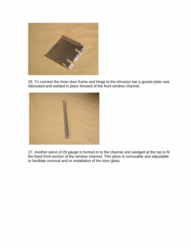
26. To connect the inner door frame and hinge to the intrusion bar a gusset plate was fabricated and welded in place forward of the front window channel.
27. Another piece of 20 gauge is formed in to the channel and wedged at the top to fit the fixed front section of the window channel. This piece is removable and adjustable to facilitate removal and or installation of the door glass.

28. Threaded inserts and a custom two-way bracket keep the bottom of the front channel in place.
29. Qty of 2 1/8 x 1 Stainless steel flats were fabricated along with qty 2 1/8 x 1 Stainless bolt plates were welded at the top window sill and lower intrusion bar with gussets.

30. The stainless up rights attach to the upper sill top and lower intrusion bar. Note the counter sunk holes to hold the power window regulator in place.
31. On the rear upright for the window regulator a tab was welded on for the window down stop. Note the slot on the regulator arm allows for adjustment if needed.

32. To tie it all together more material was laid out to fabricate an inner door panel, which will also hold the future interior door-opening lever. In addition access holes were located in key locations and cut out with a hole saw.
33. The edges of the access holes were stepped and rolled with a ½ inch bead to stiffen the panel.

34. A ½ x ½ angle strip was fabricated and then fitted along the outer edge using the stretcher/shrinker and spot welded in place using clamps to complete the panel.
35. As seen we have fitted the inner door panel brace and welded it in place.

36. We chose small bear claw latches that included door panel corners pre-notched for the latch.
37. Because of the close tolerance in our door to provide space for glass, power mechanism, and door opening rods a nut and bolt combo would interfere with the window channel. We tapped the latch mounting holes and heli-coiled them thus eliminating the need for a lock nut. As our recessed Philips screws will tighten the unit in place just fine.
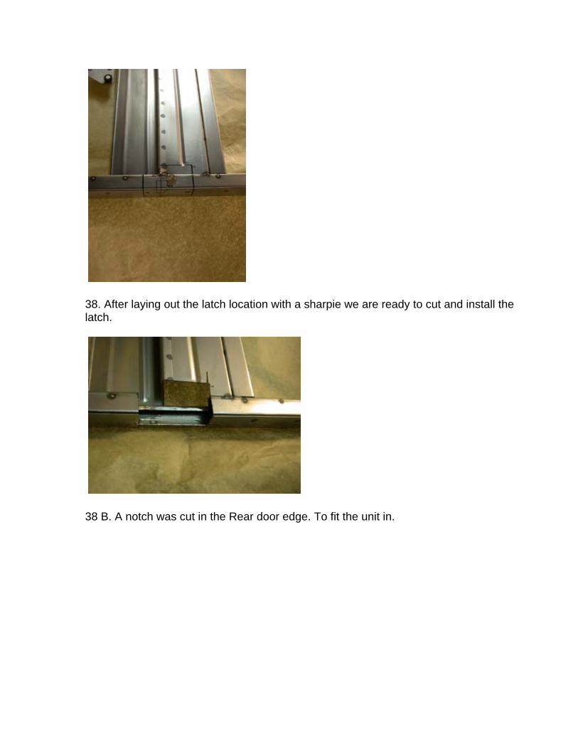
38. After laying out the latch location with a sharpie we are ready to cut and install the latch.
38 B. A notch was cut in the Rear door edge. To fit the unit in.
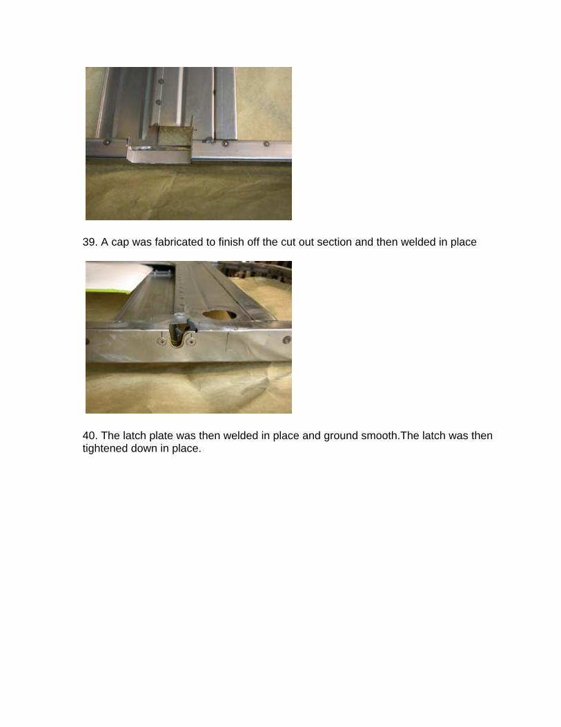
39. A cap was fabricated to finish off the cut out section and then welded in place
40. The latch plate was then welded in place and ground smooth.The latch was then tightened down in place.

Voila! A custom built Street Rod door.


![DOOR TO DOOR COLLECTION OF MSW IN CATALONIA · DOOR TO DOOR COLLECTION OF MSW IN CATALONIA ... Separate Collection Door to Door in Catalonia [1] DtD abandoned Municipalities DtD Door](https://static.documents.pub/doc/80x56/5fb98d88d1680979b16ece80/door-to-door-collection-of-msw-in-catalonia-door-to-door-collection-of-msw-in-catalonia.jpg)


