IM01500001E For more information visit wwiN.EatonEiectrical.com www . El
ectric
alPar
tMan
uals
. com
Instruction Manual Pow-R-Line Switchboards Cutler-Hammer Page 2 Effective: May 2004
Safety Measures
This publ ication contains instructions on the installation of Cutler-Hammer® brand Pow-R-Line low voltage distribution switchboards from Eaton's E lectrical business. Any person or persons that design, purchase, instal l , operate or maintain new systems utilizing these products must understand the equipment, its markings and l imitations.
Hazardous voltages in distribution switchboards and al l other electrical equipment pose a potential hazard to life and property. Please follow instructions, labeling and a pplicable codes and standards for instal lation, maintenan ce and operation of this equipment and its components. Only "Qual ified Persons" should instal l and/or service this equipment. NFPA 70- National Electrical Code® defines a "Qual ified Person" as "One who has ski l ls and knowledge related to the construction and operation of electrical equipment and installations and has received safety training on the hazards involved."
Standard symbols have been established for recognition of potentially hazardous situations and conditions. Please review and understand the critical warning symbols shown below. These symbols will appear on safety labels affixed to the product. Installer should a lways read and understand these labels before working on equipment.
I Symbol I Meaning
f � The addition of either symbol to a " Danger" or "Warning" safety label indicates that an elec-trical hazard exists which will result in personal injury if the instructions are not followed.
& This is the safety alert symbol. It is used to alert you to potential personal hazards. Obey all safety messages that follow this symbol to avoid possible injury and death.
& DANGER
"DANGER" INDICATES AN IMMINENTLY HAZARDOUS SITUATION WHICH, IF NOT AVOIDED, WILL RESULTIN DEATH OR SERIOUS INJURY .
.&. WARNING
"WARNING" INDICATES A POTENTIALLY HAZARDOUS SITUATION WHICH, IF NOT AVOIDED, CAN RESULT IN DEATH OR SERIOUS INJURY .
.&. CAUTION
"CAUTION" INDICATES A POTENTIALLY HAZARDOUS SITUATION WHICH, IF NOT AVOIDED, CAN RESULTIN MINOR OR MODERATE INJURY.
CAUTION
"CAUTION", USED WITHOUT THE SAFETY ALERT SYMBOL, INDICATES A POTENTIALLY HAZARDOUS SITUATION WHICH, IF NOT AVOIDED, CAN RESULTIN PROPERTY DAMAGE.
Eaton Corporation's l iabi l ity for any errors or omissions in this document is l imited to the documentary correction of errors. Eaton wil l not be responsible in any event for errors or omissions in this document or for any damages, incidental or consequential ( including monetary losses), that might arise from the use of this document or the information contained in it. Information in this publication is not intended for use as a training manual for non-qual ified personnel. The information or statements in th is publication concerning the suitabil ity, capacity or performance of the switchboard(s) may not cover all configurations of this custom built product. Eaton has made all reasonable efforts to ensu re that the instructions in this document are adequate and free of material errors and omissions. Eaton will, if necessary, explain issues, which may not be covered by the document. The information contained in the Instruction Leaflet is subject to change without notice.
Introduction This instruction manual is designed to supplement other industry standards including all local, state and federal codes and safety regulations, such as OSHA, NFPA 70 (National E lectrical Code), N FPA 70E (Standard for E lectrical Safety Requirements for E mployee Workplaces), NEMA® PB2.1 - Genera/Instructions for Proper Handling, Installation, Operation and Maintenance of Deadfront Distribution Switchboards Rated 600 Volts and Less, other workplace, electrical installation requirements and all safety rules.
Safety Due to the weight and size of switchboards and dangers from electrical hazards, every precaution should be taken to maintain safe working conditions when handling this equipment. Due to the custom nature of switchboards and the site variables, every potential situation cannot be anticipated. Safety must always be the overriding factor.
Always follow al l instructions and a l l safety guidel ines publ ished by OSHA and other industry and local , state and federal agencies.
For more information visit: www.EatonEiectrical.com I M01500001 E www . El
Receiving U pon del ivery, use the packing list to confirm the number of items against what was received to ensure that the shipment is complete. Any discrepancies should be noted on the freight bil l before signing. Report any shortages or damage to the freight carrier immediately.
I mmediately upon receipt of the switchboard, the plastic covering should be careful ly removed and a thorough inspection of each section should be made to detect any damage incurred during shipment. Any damage should be noted on the bill of lading (freight bill) and the consignee receiving the equipment should notify the freight carrier. FAILURE TO NOTIFY THE FREIGHT CARRIER OF DAMAGE rN A TIMELY MANNER MAY RESULT IN THE CONSIGNEE ASSUMING THE COSTS ASSOCIATED WITH REPAIR OR REPLACEMENT OF DAMAGED EQUIPMENT.
After inspection, it is recommended that a plastic covering be used to protect the equipment from dust, dirt, moisture and damage until ready for instal lation.
The switchboard should remain attached to its shipping skid until it has been moved into its final instal lation position.
Handling
& WARNING
SWITCHBOARD IS TOP HEAVY. USE CARE IN HANDLING.
Switchboards are top heavy. Switchboard sections may weigh over 2000 pounds. Before moving or lifting, verify that the equ ipment used to handle the switchboard is within safe limits of its l ifting capacity.
Switchboard shipping lengths will vary. Each shipping section is bolted with lag bolts to heavy wooden skids that extend beyond al l sides of the switchboard.
Effective: May 2004 Page 3
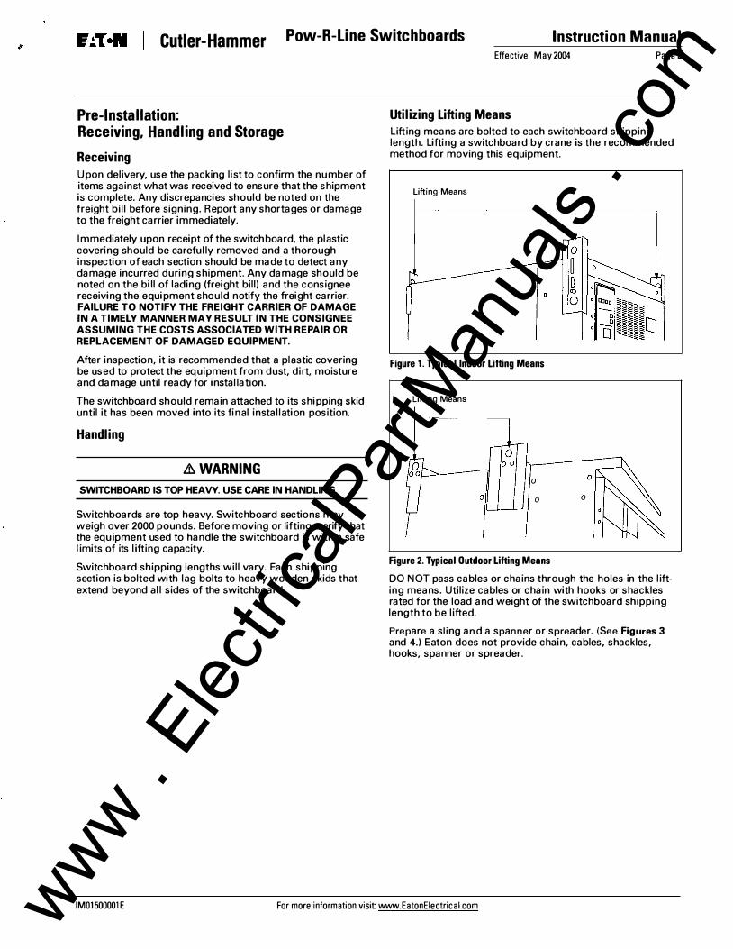
Utilizing Lifting Means Lifting means are bolted to each switchboard shipping length. Lifting a switchboard by crane is the recommended method for moving this equipment.
Lifting Means
Figure 1. Typical Indoor Lifting Means
Lifting Means
0
0 0
Figure 2. Typical Outdoor Lifting Means
DO NOT pass cables or chains through the holes in the l ifting means. Utilize cables or chain with hooks or shackles rated for the load and weight of the switchboard shipping length to be l ifted.
Prepare a sling and a spanner or spreader. (See Figures 3 and 4.) Eaton does not provide chain, cables, shackles, hooks, spanner or spreader.
IM01500001E For more information visit www.EatonEiectrical.com www . El
ectric
alPar
tMan
uals
. com
Instruction Manual
Page 4 Effective: May 2004
Spreader Bar
Figure 3. Front View
Figure 4. Side View
Pow-R-Line Switchboards Cutler-Hammer
Chains/cables must be securely attached to hooks, eyes and shackles and the spanner/spreader. Prior to lifting, check the security of the rigging assembly. Use the crane to bring the assembly taut without raising the switchboard from the floor.
Check the security of the rigging, again. Make any adjustments necessary before moving the equipment.
Slowly lift equipment to the minimum height from the floor required to safely relocate it. Move the equipment to approximately 2 inches above its resting place. Safely make a visual inspection of the rigging. If necessary, return the switchboard to its original resting place to make any modifications necessary to the rigging.
Forklifts A forkl ift may be uti l ized for handling switchboards. Only personnel trained for that equipment should operate forkl ifts.
Be sure that the ground surface is solid and fol low al l safety recommendations for operating the forklift. Be aware of wet or sl ick floors and surfaces, which can affect stopping and turning. Check labeling on the switchboard packaging material for additional information.
Verify that the forkl ift load and lifting ratings are with in safe l imits for the weight of the switchboard being l ifted.
Do not l ift switchboard from the front. Damage to components, such as breakers, fusible switches and metering, can result.
&. CAUTION
SWITCHBOARD IS TOP HEAVY. USE CARE IN HANDLING.
Forks Under Entire Switchboard
Figure 5. Forklift
Switchboard
Note: Always use caution when moving switchboards, which are top-heavy equipment.
The forks or blades of the forkl ift must run through the entire switchboard shipping length and shal l be extended to the outermost sides of the wooden shipping skids. (See Figure 5.)
Secure the switchboard with a safety strap, belt or leash approved for this purpose. Take care in positioning of the strap to ensure stabil ity of the equipment and confi rm that it is not in an area that will damage components.
Slowly lift equipment to the minimum height from the floor required to safely relocate it.
For more information visit: www.EatonEiectrical.com IM01500001E
Rollers Rollers should only be used on solid and flat surfaces, such as a finished floor. Only use rollers suitable for this purpose.
Storage Switchboards, which cannot be immediately insta l led and energized, should be stored in an indoor dry, clean and heated environment.
Do not store in areas where conditions such as dampness, changes in temperature, cement dust or a corrosive atmosphere is present.
Should the storage area be prone to moisture condensation, take precaution by making sure that the switchboard is covered and install temporary heating equipment. Approximately 250 watts per vertical section are required for average conditions.
Switchboards should be placed on solid, level surfaces for storage. Switchboard sections must remain in an upright position at all times. Laying switchboard sections on their back or side can result in permanent damage to components and the switchboard structure.
Outdoor switchboards are not weather resistant until completely and properly instal led and energized. Additional ly, uti lizing temporary heating as described above should keep an un-energized outdoor switchboard dry internal ly.
Effective: May 2004 Page 5
Pre-lnsta llation Preparation
The permanent location of switchboards must be on a smooth, solid and level foundation. Alignment is verified in the factory prior to shipment.
An uneven foundation can cause misalignment of sections, units, doors and other parts.
If a housekeeping pad is uti l ized, check factory drawings and verify handle height rules relative to the National E lectrical Code (NEC) and uti l ity meter heights where appl icable.
When embedded anchors or channel sil ls are used, materials and attachments must be adequate to support the structure(s). Switchboard sections must be a l igned and level over the length of the installation.
From manufacturer's drawings, determine the layout of the electrical distribution equipment for each location. Verify and confirm that the avai lable equipment space and equipment location(s) is in compliance with the minimum working space clearances per the NEC.
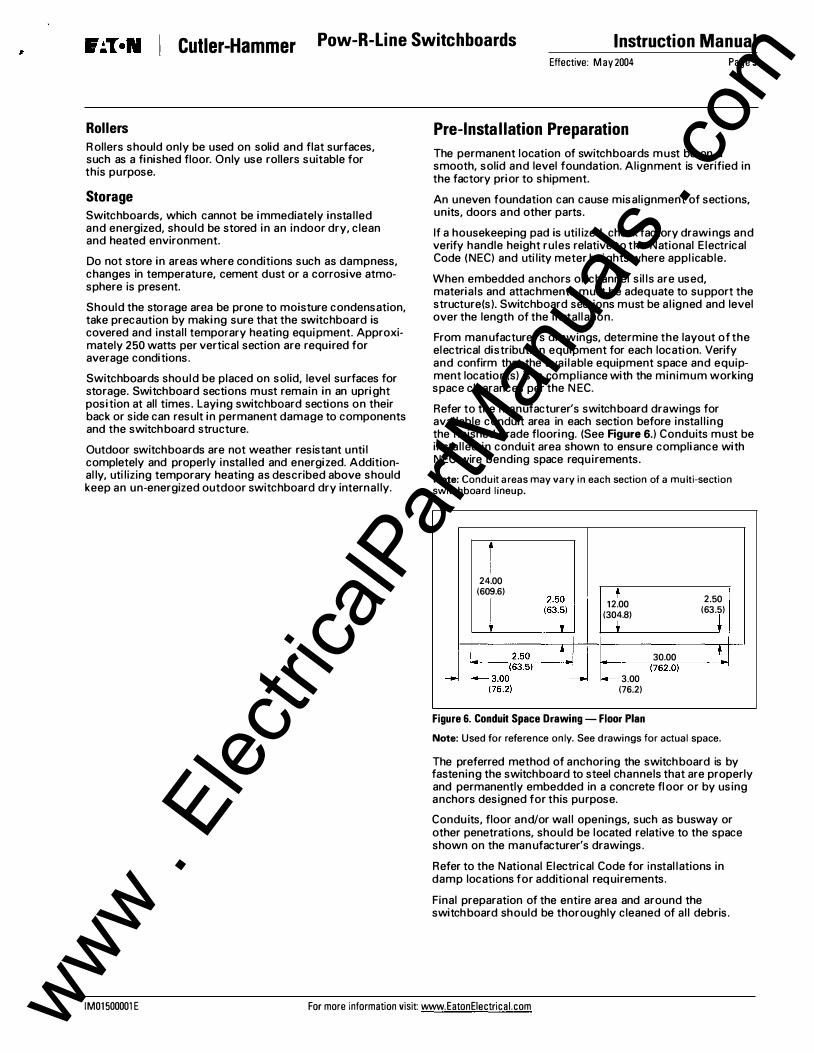
Refer to the manufacturer's switchboard drawings for available conduit area in each section before instal l ing the finished grade flooring. (See Figure 6.) Conduits must be installed in conduit area shown to ensure compliance with NEC wire bending space requirements.
Note: Conduit areas may vary in each section of a multi-section switchboard lineup.
J
24.00 (609.6)
12.00 (304.8)
2.50 (63.5)
30.00 �----,(762.0)---�
3.00 (76.2)
Figure 6. Conduit Space Drawing- Floor Plan
Note: Used for reference only. See drawings for actual space.
The preferred method of anchoring the switchboard is by fastening the switchboard to steel channels that are properly and permanently embedded in a concrete floor or by using anchors designed for this purpose.
Condu its, floor and/or wal l openings, such as busway or other penetrations, should be located relative to the space shown on the manufacturer's drawings.
Refer to the National Electri cal Code for instal lations in damp locations for additional requirements.
Final preparation of the entire area and around the switchboard should be thoroughly cleaned of al l debris.
IM01500001 E For more information visit: www.EatonEiectrical.com www . El
ectric
alPar
tMan
uals
. com
Instruction Manual Pow-R-Line Switchboards Cutler-Hammer Page 6 Effective: May 2004
Considerations for Seismic Qualified Installations
Switchboards that are "Seismical ly Qual ified" requ ire additional considerations. Since electrical equipment is instal led as part of a system, pre-engineering layouts are critical in seismic applications.
When seismic qual ified and marked Cutler-Hammer brand switchboards are used, anchoring the switchboard recommended by the design engineer is critica l . Experienced engineers in seismic requi rements should select methods and techniques of attachment and tested anchoring systems. Embedded concrete anchors or steel attachments must be adequate to resist the forces establ ished by the local building code. Bolts of the proper grade of steel must be correctly sized and torqued. The embedded anchors must be correctly instal led in a ccordance with the method specified by the anchor manufacturer.
Conduit layout in concrete for loads entering and/or exiting the bottom must be designed and instal led to prevent damage from an earthquake. If top entry is necessary, seismic fittings or flexible conduit is needed.
Consult applicable local building codes and regulatory agencies for other specific requirements for seismic insta l lations.
Additional ly, six (6) inches of space should be added to the length of the switchboard assembly to accommodate seismic anchor plates. Contact Eaton for additional information.
Installation
Use caution and appropriate equipment and practices when moving switchboard into its fi nal position .
Lh CAUTION
SWITCHBOARD IS TOP HEAVY. USE CARE IN HANDLING.
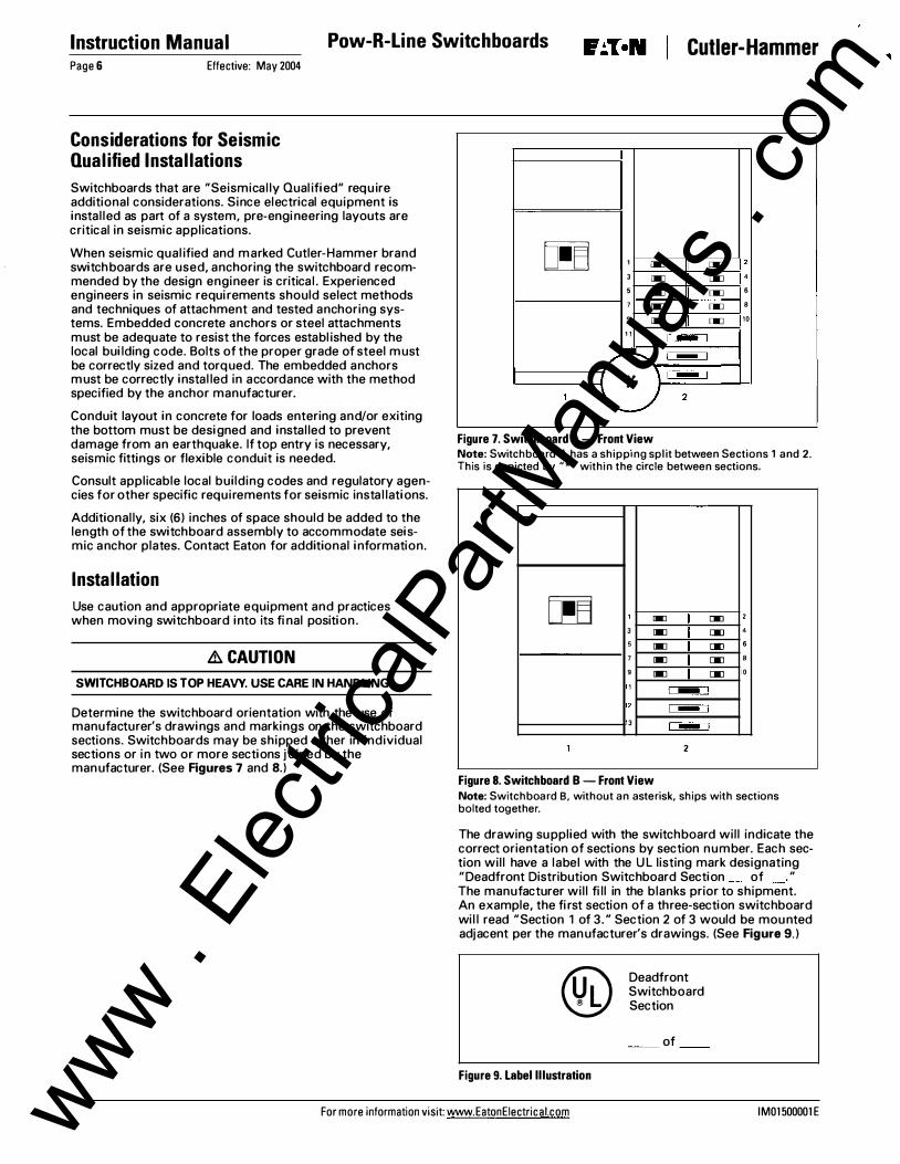
Determine the switchboard orientation with the use of manufacturer's drawings and markings on the switchboard sections. Switchboards may be shipped either in individual sections or in two or more sections joined by the manufacturer. (See Figures 7 and 8.)
00 1 � [I] 2
3 � [I] 4
5 � [I] 6
7 � [I] 8
9 � [I] 10
11 ,_, • ,_,
--, * ,,_,
1 2
Figure 7. Switchboard A- Front View Note: Switchboard A has a shipping split between Sections 1 and 2. This is depicted by "*" within the circle between sections.
00 1 � IIl 2
3 � IIl 4
5 � [)[] 6
7 � [)[] 8
9 � [)[] 0
1 ,_, 2 ,_, 3 1-1
2
Figure 8. Switchboard B - Front View Note: Switchboard B, without an asterisk, ships with sections bolted together.
The drawing supplied with the switchboard will indicate the correct orientation of sections by section number. Each section will have a label with the U L listing mark designating "Deadfront Distribution Switchboard Section of " The manufacturer will fi ll in the blanks prior to shipment. An example, the fi rst section of a three-section switchboard wil l read "Section 1 of 3." Section 2 of 3 would be mounted adjacent per the manufacturer's drawings. (See Figure 9.)
® Figure 9. Label Illustration
Deadfront Switchboard Section
of
For more information visit: www.EatonEiectrical.com IM01500001E www . El
Alignment of multi-section switchboards is designed to be front and rear al igned or rear (only) al igned. Drawings provided by the manufacturer and located in the switchboard will show footprint details. Orientation, as shown on the drawings, must be maintained. (See Figures 10 and 11.)
Switchboard Front Top View
Figure 10. Example of Front and Rear Aligned Switchboard
Switchboard Front Top View
Figure 11. Example of Rear Aligned Switchboard
Sections may contain factory cross bus and/or cable to connect power between switchboard structures and other components. Installers should note the location and orientation of al l splice plates and/or cables as reference for installation once sections are joined.
If supplied, remove spl ice plates and associated hardware, again noting the orientation for re-instal lation once switchboard is in place. If additional hardware is needed to complete these connections, extra hardware will be provided. For shipping purposes, it wil l typical ly be secured inside one of the structures. Keep bus and hardware in a clean and protected environment to guard against damage until re-instal lation. Protect any factory-installed cables (wire) used to connect components between sections from damage when moving switchboard sections into place.
An outdoor multi-section switchboard will ship with un-installed intermediate roof cap(s) for each joint between sections. Remove roof cap(s) prior to moving sections into their permanent position. Retain roof cap(s) and associated hardware for re-installation. Keep roof caps and associated hardware in a clean and protected environment to guard against damage awaiting re-installation.
There are two roof designs for outdoor switchboards. These are the flat roof design and the sloped roof design.
The standard outdoor switchboard uti l izes a flat roof design. This design does not require any sealant when the intermediate roof cap is correctly insta l led in the field.
The optional sloped roof outdoor design also uses an intermediate roof cap design. When a break occurs between sections for shipping purposes, the intermediate roof cap on the optional outdoor sloped roof design shall have a 3/16" minimum bead of sil icone sealant (RTV 732) appl ied to the underneath side of the roof cap. Each roof cap should have two (2) continuous beads of sealant from end to end. Each bead must be located between the row of mounting holes and the outer edge of the roof cap. A tube of sealant is provided with every outdoor switchboard for customer's use.
Effective: May 2004 Page 7
Use caution and appropriate equipment and practices when moving switchboard into its final position.
&WARNING
SWITCHBOARD IS TOP HEAVY. USE CARE IN HANDLING.
Exercise caution while maneuvering top-heavy switchboard sections into place. Switchboard sections must always remain in the upright position during instal lation. Use care when moving the switchboard so not to damage the section, including the structural base and frame. Some switchboards house sensitive components, which can be damaged by rough handling.
Prior to moving the switchboard sections into its permanent position, make note of all obstacles including conduit stubs. Implement a plan for safe transition and appropriate means to accommodate these obstructions. Take note of condu its entering through the bottom of the switchboard, rear of the switchboard, and at the top of the switchboard to ensure appropriate clearances from chassis, structure, cross bus, ground, neutral and components.
Provide space for a minimum 1/2" clearance from back of switchboard and any wall for front accessible switchboards installed indoors.
Front accessible switchboards, which are built and marked for outdoor instal lation, must ma intain a 6-inch minimum clearance from any wal l or building structure. For other required clearances, including rear-connected switchboard, refer to the National E lectrical Code (NEC) clearances.
When unpacking the switchboard, exercise care not to scratch or mar the finish. Repair all scratches with touchup paint, which is ava i lable from Eaton. Remove shipping skids and all packaging material . Remove any temporary shipping braces or spacers. Remove lifting angles and associated hardware. P lug l ifting angle holes with hole plugs suppl ied by the manufacturer. (See Figure 12.)
L-+--L----+1--+--- Example of Hole Plugs Installed
Figure 12. Hole Plugs Installed
Where two or more switchboard sections are to be joined together, they should first be aligned and all sections leveled.
Once aligned and level, attach switchboard sections together.
IM01500001E For more information visit www.EatonEiectrical.com www . El
ectric
alPar
tMan
uals
. com
Instruction Manual Pow-R-Line Switchboards Cutler-Hammer Page 8 Effective: May 2004
Attaching Switchboard Sections The manufacturer has provided hardware with the equipment to join switchboard sections. The hardware includes 3/8" x 1" carriage bolts and 3/8" hex nuts with captive Bellevil le-type washer. (See Figure 13.)
Holes are provided on the side of each switchboard section for this purpose. Three holes are located on the side of each section towards the front and back. Switchboards with deep designs, including rear-connected switchboards, may have an additional three holes for attachment on the center vertical section support. (See Figure 14.)
Figure 13. Hardware
Carriage bolt and hex nut with Belleville washer.
Section connection with carriage bolt and hex nut with Belleville washer.
Figure 14. Switchboard Section Connection
Bolt sections together using fasteners supplied by the manufacturer.
Figure 15. Joining Switchboard Sections
Join sections utilizing the carriage bolts and hex nuts with captive Bellevil le-type washer through the holes provided. (See Figure 15.) While maintaining level and a l ignment of the structures, torque each connection to the values shown in Appendix Table 2.
If switchboard sections are outdoor type, re-install roof cap(s). Visual ly inspect the roof cap to ensure a rel iable, permanent watertight fit prior to energizing the switchboard.
Once the switchboard structures are attached, visually inspect the board for foreign objects and visual ly inspect the structure for proper clearances of live parts.
For more information visit: www.EatonEiectrical.com IM01500001E www . El
Several methods may be used to make electrical connections within switchboards. More than one of these methods may be used in a section and/or switchboard l ineup. These include bus splice plates, factory installed cable and busway connections. Consult the manufacturer's drawings for details for each switchboard section.
Remove structure deadfront covers and side sheets as needed to access switchboard chassis and components. Retain a l l cover mounting hardware and covers for re-assembly. Protect hardware and parts from moisture, debris and damage.
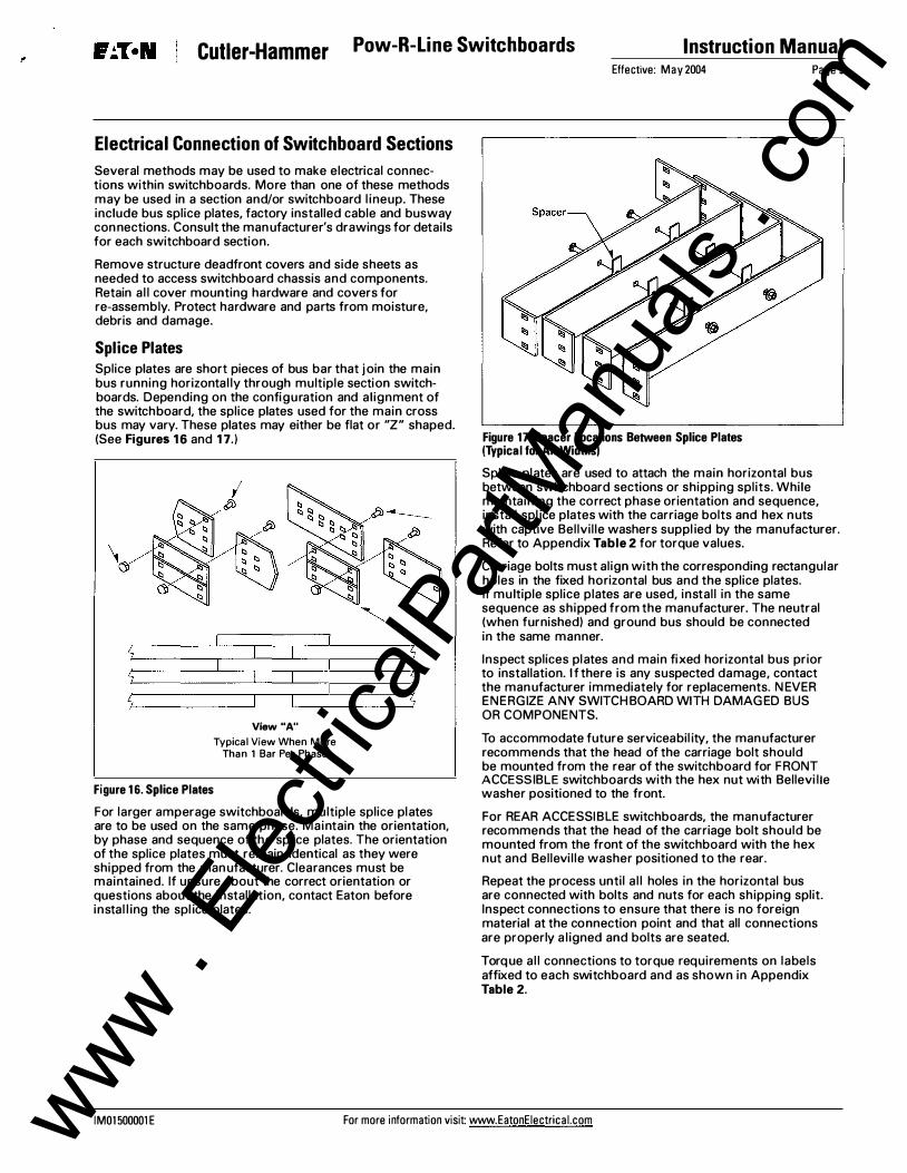
Splice Plates Splice plates are short pieces of bus bar that join the main bus running horizontal ly through multiple section switchboards. Depending on the configuration and al ignment of the switchboard, the splice plates used for the main cross bus may vary. These plates may either be flat or "Z" shaped. (See Figures 16 and 17.)
Figure 16. Splice Plates
View"A"
Typical View When More Than 1 Bar Per Phase
For larger amperage switchboards, multiple splice plates are to be used on the same phase. Maintain the orientation, by phase and sequence of the splice plates. The orientation of the splice plates must remain identical as they were shipped from the manufacturer. Clearances must be maintained. If unsure about the correct orientation or questions about the installation, contact Eaton before instal l ing the spl ice plates.
Effective: May 2004
Figure 17. Spacer Locations Between Splice Plates (Typical for All Widths)
Page 9
Splice plates are used to attach the main horizontal bus between switchboard sections or shipping splits. While ma intaining the correct phase orientation and sequence, install spl ice plates with the carriage bolts and hex nuts with captive Bellvil le washers suppl ied by the manufacturer. Refer to Appendix Table 2 for torque values.
Carriage bolts must align with the corresponding rectangular holes in the fixed horizontal bus and the splice plates. If multiple splice plates are used, install in the same sequence as shipped from the manufacturer. The neutral (when furnished) and ground bus should be connected in the same manner.
Inspect splices plates and main fi xed horizontal bus prior to installation. If there is any suspected damage, contact the manufacturer immediately for replacements. N EVER ENERGIZE ANY SWITCH BOARD WITH DAMAGED BUS OR COMPONENTS.
To accommodate future serviceabil ity, the manufacturer recommends that the head of the carriage bolt should be mounted from the rear of the switchboard for FRONT ACCESSIBLE switchboards with the hex nut with Bellevi l le washer positioned to the front.
For REAR ACCESSIBLE switchboards, the manufacturer recommends that the head of the carriage bolt should be mounted from the front of the switchboard with the hex nut and Bellevi l le washer positioned to the rear.
Repeat the process until a l l holes in the horizontal bus are connected with bolts and nuts for each shipping split. Inspect connections to ensure that there is no foreign material at the connection point and that all connections are properly a l igned and bolts are seated.
Torque al l connections to torque requirements on labels affixed to each switchboard and as shown in Appendix Table 2.
IM01500001E For more information visit: www.EatonEiectrical.com www . El
ectric
alPar
tMan
uals
. com
Instruction Manual Pow-R-Line Switchboards Cutler-Hammer Page 10 Effective: May 2004
IFS Switchboard Factory Cabling Some switchboards utilize cable/wire for some connections in lieu of bus. Cabling is typical in Integrated Facil ity System™ ( IFS™) type switchboards that incorporate l ighting and appliance branch circuit panelboards and dry-type distribution transformers with in a switchboard l ineup.
Eaton's selection of wire and cable follows U L891 switchboard procedures, N ational E lectrical Manufacturers Association, Federal Specification standards, and the National Electrical Code standards for IFS switchboards.
The manufacturer identifies each phase conductor by means of color-coded tape with markings "Factory Instal led" in I FS switchboards. Markings are affixed to both the line and load ends of the conductors. Markings follow the industry accepted phase colors. (See Figure 18 and Table 1.)
Factory Instal led
Figure 18. Typical Phase "A" 240 Vac Wire Label
Table 1. Wire Label Color Codes
240 Vac Systems Systems Above and Below Nominal 240 Vac Nominal
Phase A Black Phase A Phase B Red Phase B Phase C Blue Phase C Neutral White Neutral Ground Green Ground
Brown Orange Yellow Gray Green
Conductors instal led by the manufacturer have been cut and stripped to pre-determined lengths for connection between components. When conductors are intended to run between components in two different sections that are joined by the manufacturer, the manufacturer will connect both the line and load ends of the conductors.
Note: The National Electrical Code restricts the field installation of conductors that run horizontally through switchboard vertical sections. Refer to the NEC for specifics.
When there is a shipping split between sections that are cabled, the factory connects one end of the conductors. The remainder of the conductors are coi led and secured in the section with the connection.
Factory drawings included in the switchboard clearly indicate the required field connections for the coi led conductors.
Inspect conductors/cables for damage. Any damaged conductors must be replaced. Contact manufacturer for replacement.
Factory color-coded markings indicate phasing/neutral and are marked on both the l ine and load ends of the conductors.
Using the factory drawings, the instal ler connects conductors to the component(s) indicated on the drawings keeping phases correctly oriented. Care should be taken in forming insulated cables to ensure that no insulation is forced permanently against edges of any metal parts.
Torque both l ine and load connections to values indicated on the labeling on the switchboard. Refer to Appendix Table 2 for torque values.
Installation of Incoming Switchboard Connections
& DAN G E R
DE-ENERGIZE SWITCHBOARD- HAZARDOUS VOLTAGE. WILL CAUSE SEVERE INJURY OR DEATH.
DO NOT work on electrical equipment while energized. Verify power entering the equipment is de-energized at the source.
Power is normally brought into a switchboard either by cable or by busway (busduct).
Remove structure covers as needed to access switchboard chassis and components. Retain a l l cover mounting hardware and covers for re-assembly. Protect hardware and parts from moisture, debris and damage.
Note: As a minimum, all switchboard connections are rated for use with 75°C or higher rated conductors. When wire is used with temperature ratings above 75°C, it shall be sized based on the ampacity of wire rated 75°C.
Wire/Cabling
When cable connections are used, either mechanical set screw or compression lugs are typically supplied. (See Figure 19.) See factory drawing for specific lug terminations and wire ranges. Some utilities make their own service entrance connections. In these cases, the manufacturer typical ly supplies lug landing provisions or a landing pad in l ieu of lugs. These are designed to the specific util ity's requirements. Refer to the manufacturer's drawings for specifics covering this connection.
Mechanical Set Screw Lug
Standard One Hole Compression Type Lug
Optional Two Hole Compression Type Lug
Figure 19. Screw and Compression Lugs
Unless a switchboard specifical ly restricts entry to a single means or area, cables may enter through the top, bottom, side or back of the main incoming section. These restrictions are typically required to conform to wire bending space requirements of the NEC. Consult the manufacturer's drawings for conduit entry data.
For more information visit: www.EatonEiectrical.com IM01500001E www . El
Once the conductors are pul led inside the main section, the cables should be formed in the space provided. Clearly identify and segregate conductors by phase and neutral. Care should be taken in forming insulated cables to ensure that no insulation is forced permanently against the edges of any metal parts.
Using appropriate tools, the installer must strip the conductor insulation sufficiently to fill the entire barrel of the connector with bare, un-insulated conductor. Conductor must be stripped without damage to the conductor strands. Bare strands should be of equal length (fl ush) on the end cut.
Do not strip off more insulation than needed. Exposure of bare conductor outside lug can compromise clearances.
The connector and conductor should be free of all foreign debris.
Never clip cable/wire strands in order to fit within connectors. If cable/wire does not match the rating of the connector, contact the manufacturer.
Mechanical set screw lugs are the most common. Use an antioxidant compound, if required. Insert bare conductor into lug so the bare conductor fi l ls the ful l length of the lug body. Tighten lug, then torque to levels indicated on the switchboard label.
If compression lugs are util ized and supplied with the switchboard, the lugs will be mounted on the incoming lug pad. Remove lugs from the pad. Use an antioxidant compound, if required. Use a crimping tool approved for that specific lug manufacturer and lug size. Follow instructions provided by the manufacturer of the crimp tool .
Once the lug is affixed to the conductor, re-install the lug on the lug pad uti l izing the existing hardware. Torque hardware using information provided on switchboard labeling. Refer to Appendix Table 2 for torque values.
Effective: May 2004 Page 11
Other Requirements for Rear Connected Switchboards On systems that require short circuit current ratings above 10,000 amperes rms, Cable Bracing may be required to restrict cable movement. Lashing and lacing cables accomplish this.
Cable Bracing Instructions
For short-circuit ratings above 10,000 amperes rms, install cable braces per the following instructions:
1. The material required for the cable braces is 3/8" diameter nylon rope G:l or any rope having a minimum tensile strength of 2,000 pounds. ®
2. All cable conductors of a load circuit are to be bundled together with five adjacent wraps of rope at distances of 6 inches and 1 2 inches from the supply terminals for ratings up to 200 amperes maximum. (See Figures 20 and 21.)
G:l Wellington Puritan Mills, Inc., Madison, GA., Catalog Number 10989 ® Norva Products, Carrolton, GA., Catalog Number TPR12
Cable Lugs
Figure 20. Cable Bracing
Cable Lugs
Optional Cable Support
Application
Typical Side View
Figure 21. Cable Bracing
Cable
5"""""
�
blo
Support� Cable Support
Detail
IM01500001 E For more information visit www.EatonEiectrical.com www . El
ectric
alPar
tMan
uals
. com
Instruction Manual Pow-R-Line Switchboards Cutler-Hammer Page 12 Effective: May 2004
Busway A switchboard may include one or more provisions for connection to Cutler-Hammer brand busway. Busway can feed the switchboard, be fed from the load side of an overcurrent device within the switchboard, or both.
Switchboards with busway connection(s) contain fl ange connection 'tie-bar(s)' assembled in the appropriate section. The tie-bars will accept the corresponding busway flange extension. Consult switchboard and busway drawings for specifics. The tie-bars are a transition between the switchboard conductors and the busway flange extension, and are assembled as part of the switchboard section.
Figure 22. Downward Elbow Right Flange
Figure 23. Standard Flange
11.62 (295.2)
y
1
The switchboard flange has a corresponding piece shipped with the busway run. The busway insta l ler attaches the two flange pieces together prior to energization. (See Figures 22 and 23.)
Recommened Hardware for Bolting to Flange Extensions
Phase Bus
92.00 t Extension
(2336.8) .--�--fllut--i=!>� .375 Hardware Hex Head Bolt .-�-.11(11_,_._,
Side View of Busduct Aligned From Rear of Switchboard
Figure 24. Busway/Busduct
The bus assembly is completely formed and dri lled for connections, including phase bussing and neutral, if needed. Additional ly, grounding connections are suppl ied.
Busway typica l ly enters a switchboard section through the top. However, busway may attach from the bottom, back or side of the switchboard in special configurations. (See Figure 24.)
Temporary bracing may be provided to support the busway assembly in the switchboard during shipment. All temporary bracing must be removed after connections are completed.
The switchboard structure should NOT be used to support any busway run or flange and extension.
Bolts and hex nuts with captive Belleville washers are supplied by the manufacturer with the switchboard to connect the switchboard insta l led flange and the busway flange. Follow instructions shipped with the switchboard and with busway flange.
When a busway connection is supplied on an outdoor switchboard, sealing the busway connection is very critical . Upon completing the necessary bus connection, the instal ler is responsible for sealing the connection point where the busway flange connects to the chimney top cover or side/ rear cover. A tube of RTV 732 si l icone sealant and a rol l of gasketing material are provided with the switchboard for this purpose.
For installation instructions on busway runs, please refer to N EMA publication BU 1.1 -2000, Genera/Instructions for Handling, Installation, Operation and Maintenance of Busway Rated 600 Volts or Less.
For more information visit: www.EatonEiectrical.com IM01500001E www . El
Pre-Energizing Procedures and Inspection Before energizing any switchboard, perform a comprehensive inspection to make certain that the switchboard is ready to be energized. This includes the fol lowing steps:
1 . Verify that the switchboard is not energized.
2. Visual ly inspect the switchboard and remove all foreign materials, such as, tools, scraps of wire and other debris from all switchboard sections.
3. Remove and discard al l packing materials and temporary shipping braces from the switchboard.
4. Any accumulation of dust and dirt should be removed with a vacuum cleaner. Use a l int-free cloth to remove dust and dirt on other surfaces. Never use compressed a ir as this may blow contaminants into electrical and/or electronic components. Never use solvents or other chemicals to clean surfaces or components.
5. Visual ly inspect all ventilation points to ensure that there is no blockage or debris. Remove a l l debris, if present.
6. Verify all field bus and wire connections have the proper torque per instructions on the switchboard and on components.
7. All factory connections are made uti l izing calibrated power tools. However, vibrations do occur in transit and handling. Verify factory connections by checking at least 10% of the total factory connections for tightness. If this spot check reveals loose connections, proceed to check all factory connections. These connections include bus hardware connections, circuit breaker and switch terminals, contactors, metering and other connections, including the incoming terminals.
8. Visual ly inspect switchboard insulators, bus bar and conductors for damage. DO NOT ENERGIZE IF DAMAGE IS FOUND. Contact Eaton.
9. If fusible switch type overcurrent devices are used, verify proper fusing has been selected and installed. Eaton does not typica l ly supply switchboards with these fuses.
Overcurrent Devices
Overcurrent devices are typically shipped in either the open (OFF) or "tripped" position. Manual ly close, and then open these devices to ensure they are functioning properly. At the completion of this process, be sure that the overcurrent device is in the "OFF" or "tripped" position.
Inspect overcurrent devices for any visible damage. If damage is found, DO NOT ENERGIZE the switchboard. Contact Eaton.
Effective: May 2004 Page 13
Circuit Breakers
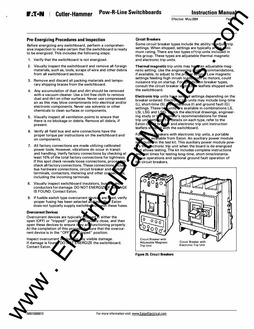
Some circuit breaker types include the abi l ity to a djust trip settings. When shipped, settings are typical ly at the minimum rating. There are two types of tr ip units included in this group. These types are adjustable thermal magnetic and electronic trip units.
Thermal magnetic trip units may have an adjustable magnetic setting. Use the engineering study recommendations, if avai lable, to adjust to the proper setting. Low magnetic settings feeding high inrush loads, such as motors, could nuisance trip on startup. For specifics on breaker types, consult the circuit breaker instruction leaflets shipped with the switchboard.
Electronic trip units have several settings depending on the breaker ordered. Electronic trip units may include long-time (L), short-time (S), instantaneous (I) and ground fault (G) settings. These trip units are available in combinations LS, LSI, LSG and LSIG. Check the electrical drawings, engineering study or the engineer's recommendations for these trip unit settings. For detai ls on each type, refer to the Eaton circuit breaker and electronic trip unit instruction leaflets shipped with the switchboard.
For certain breakers with electronic trip units, a portable test kit is available from Eaton. An auxiliary power module is included in the test kit. This auxiliary power module powers the electronic trip unit when the board is de-energized and al lows testing. The kit includes complete instructions and test times for testing long-time, short-time/instantaneous operations and optional ground fault operation of the circuit breakers.
Circuit Breaker with Adjustable Magnetic Trip Unit
Figure 25. Circuit Breakers
Circuit Breaker with Electronic Trip Unit
IM01500001E For more information visit www.EatonEiectrical.com www . El
ectric
alPar
tMan
uals
. com
Instruction Manual Pow-R-Line Switchboards Cutler-Hammer Page 14 Effective: May 2004
Overcurrent Devices with Ground Fault Protection This switchboard may contain overcurrent devices with Ground Fault Protection (GFP). The National Electrical Code may require ground fault protection for this installation. Other GFP appl ications may be used including multi-level ground fault protection. Refer to the switchboard drawings and electrical construction drawings for usage and placement within the switchboard.
Ground fault protection may be installed integral to overcurrent device(s) or as a separate system. Separate systems typically are connected to a shunt tripping mechanism on an overcurrent device.
Visibly inspect connections on GFP systems, neutral sensors and ground connections. Refer to manufacturer's instructions for details.
Prior to shipment, the manufacturer has pre-set the ground fault protection at minimum set points. Adjust settings per engineered electrical plan drawings. lf this information is not readi ly avai lable, contact the design engineer or other qual ified persons responsible for the specifics of the installation and system design.
Prior to testing the GFP system, remove the neutral disconnect l ink(s) on the switchboard to isolate the neutral of the system from the supply and ground.
Confirm that the neutral connection has been run from the supply to the service equ ipment per the National Electrical Code.
The N ational Electrical Code, Article 230-95 requires that any GFP systems must be performance tested when fi rst instal led. Conduct tests in accordance with the approved instructions provided with the equipment. A written test report must be avai lable for the Authority Having Jurisdiction (AHJ). Refer to the National Electrical Code for specific requirement or contact Eaton.
For certain breakers with electronic trip units, a portable test kit is ava ilable from Eaton, at additional cost. The kit includes complete instructions and test times for testing long-time, short-time/instantaneous operations and ground fault operation of the circuit breakers. Use of testing equipment other than that supplied by Eaton can cause permanent damage to the circuit breaker trip unit and will void the warranty.
.& CAUTION
DO NOT TEST A CIRCUIT BREAKER WHILE IT'S IN-SERVICE AND ENERGIZED.
.& CAUTION
TESTING OF A CIRCUIT BREAKER THAT RESULTS IN THE TRIPPING OF THE CIRCUIT BREAKER SHOULD BE DONE ONLY WHEN THE SWITCHBOARD IS DE-ENERGIZED.
Field-testing of ground fault protection must follow instructions provided with each GFP device. Due to the varied types of GFP systems, testing instructions can vary from device to device. Refer to the specific testing instructions for each device. Refer to instruction leaflets that are shipped with each switchboard containing GFP or contact Eaton.
Current Transformers Switchboards containing metering and monitoring equipment may contain current transformers (CTs) integral to the switchboard. Ensure that the load side of the CTs are connected or are shorted together with terminal block shorting means. Remove shorting means for normal CT operation with metering equipment. For additional information and instructions, refer to instruction leaflet shipped with the switchboard.
Preparing Switchboard for lnsulation/Megger Testing
.& CAUTION
FAILURE TO SHORT OR DISCONNECT DURING SWITCHBOARD TESTING WILL RESULT IN FAILURE OF ELECTRONIC COMPONENTS.
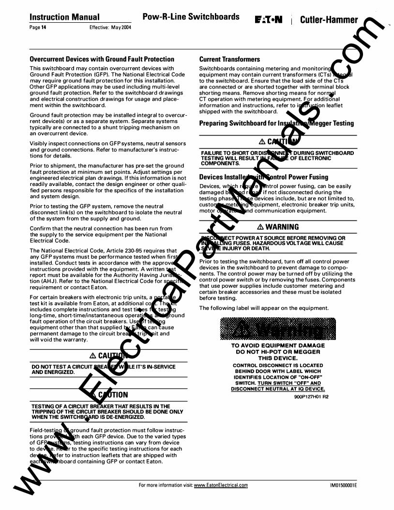
Devices Installed with Control Power Fusing Devices, which require control power fusing, can be easily damaged beyond repair if not d isconnected during the testing phase. These devices include, but are not l imited to, customer metering equipment, electronic breaker trip units, motor operators and communication equipment.
.& WARNING
DISCONNECT POWER AT SOURCE BEFORE REMOVING OR INSTALLING FUSES. HAZARDOUS VOLTAGE WILL CAUSE SEVERE INJURY OR DEATH.
Prior to testing the switchboard, turn off al l control power devices in the switchboard to prevent damage to components. The control power may be turned off by uti l izing the control power switch or by removing the fuses. Components that use power suppl ies include customer metering and certain breaker accessories and these must be isolated before testing.
The following label wil l appear on the equipment.
TO AVOID EQUIPMENT DAMAGE DO NOT HI-POT OR MEGGER
THIS DEVICE. CONTROL DISCONNECT IS LOCATED BEHIND DOOR WITH LABEL WHICH IDENTIFIES LOCATION OF "ON-QFF" SWITCH. TURN SWITCH "OFF" AND
DISCONNECT NEUTRAL AT IQ DEVICE •
900P127H01 R2
For more information visit: www.EatonEiectrical.com IM01500001E www . El
FAILURE TO DISCONNECT CONTROL POWER DURING SWITCHBOARD TESTING WILL RESULT IN FAILURE OF ELECTRONIC COMPONENTS.
Failure to disconnect control power during switchboard testing will result in failure of electronic components and void manufacturer's warranty.
Transient Voltage Surge Suppression (TVSS) and Surge Protective Devices (SPD) Prior to testing the switchboard, disconnect l ine and neutral connections to all TVSS and/or SPD units in the switchboard. Keep hardware in a clean and protected environment to guard against damage until re-installation.
& CAUTION
FAILURE TO DISCONNECT LINE AND NEUTRAL DURING TESTING WILL CAUSE THE TVSS AND SPD SURGE PROTECTION SYSTEM TO FAIL AND WILL VOID THE WARRANTY ON THE DEVICE.
Failure to disconnect line and neutral during testing will cause the TVSS and SPD surge protection system to fail and will void the warranty on the device. After testing, re-install all connections.
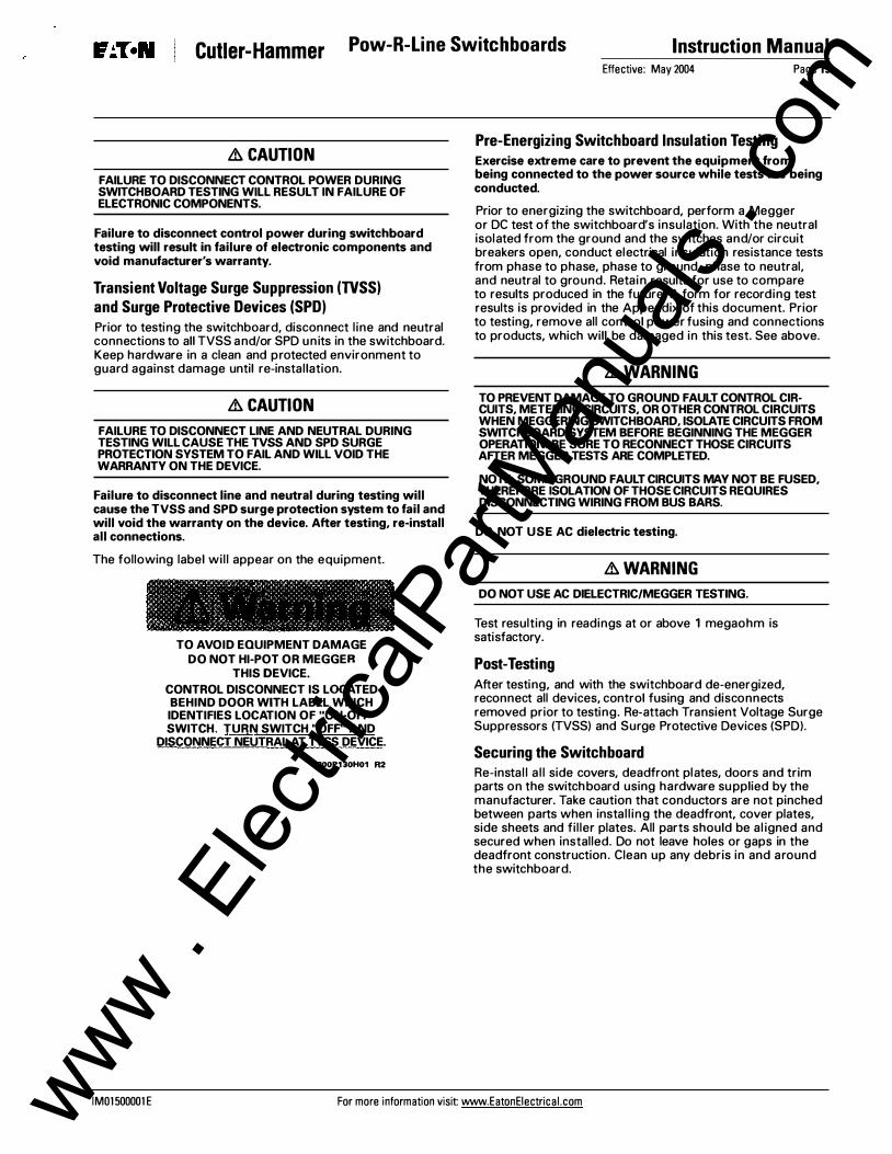
The following label wil l appear on the equipment.
TO AVOID EQUIPMENT DAMAGE DO NOT HI-POT OR MEGGER
THIS DEVICE.
CONTROL DISCONNECT IS LOCATED BEHIND DOOR WITH LABEL WHICH IDENTIFIES LOCATION OF "ON-OFF" SWITCH. TURN SWITCH "OFP' AND
DISCONNECT NEUTRAL AT TVSS DEVICE.
900P130H01 R2
Effective: May 2004 Page 15
Pre-Energizing Switchboard Insulation Testing Exercise extreme care to prevent the equipment from being connected to the power source while tests are being conducted.
Prior to energizing the switchboard, perform a Megger or DC test of the switchboard's insulation. With the neutral isolated from the ground and the switches and/or circuit breakers open, conduct electrical insulation resistance tests from phase to phase, phase to ground, phase to neutral, and neutral to ground. Retain results for use to compare to results produced in the future. A form for recording test results is provided in the Appendix of this document. Prior to testing, remove all control power fusing and connections to products, which will be damaged in this test. See above.
&WARNING
TO PREVENT DAMAGE TO GROUND FAULT CONTROL CIR· CUlTS, METERING CIRCUITS, OR OTHER CONTROL CIRCUITS WHEN MEGGERING SWITCHBOARD, ISOLATE CIRCUITS FROM SWITCHBOARD SYSTEM BEFORE BEGINNING THE MEGGER OPERATION. BE SURE TO RECONNECT THOSE CIRCUITS AFTER MEGGER TESTS ARE COMPLETED.
NOTE: SOME GROUND FAULT CIRCUITS MAY NOT BE FUSED, THEREFORE ISOLATION OF THOSE CIRCUITS REQUIRES DISCONNECTING WIRING FROM BUS BARS.
DO NOT USE AC dielectric testing.
&WARNING
DO NOT USE AC DIELECTRIC/MEGGER TESTING.
Test resulting in readings at or above 1 megaohm is satisfactory.
Post-Testing After testing, and with the switchboard de-energized, reconnect all devices, control fusing and disconnects removed prior to testing. Re-attach Transient Voltage Surge Suppressors (TVSS) and Surge Protective Devices (SPD).
Securing the Switchboard Re-instal l a l l side covers, deadfront plates, doors and trim parts on the switchboard using hardware supplied by the manufacturer. Take caution that conductors are not pinched between parts when instal l ing the deadfront, cover plates, side sheets and fil ler plates. All parts should be al igned and secured when installed. Do not leave holes or gaps in the deadfront construction . Clean up any debris in and around the switchboard.
IM01500001E For more information visit www.EatonEiectrical.com www . El
ectric
alPar
tMan
uals
. com
Instruction Manual Pow-R-Line Switchboards Cutler-Hammer Page 16 Effective: May 2004
Energizing Switchboard
.&. WARNING
HAZARDOUS VOLTAGE WILL CAUSE SEVERE INJURY OR DEATH.
.&. WARNING
ONLY THOSE PROFESSIONALS TRAINED AND QUALIFIED ON ELECTRICAL DISTRIBUTION SWITCHBOARDS SHOULD INSTALL AND/OR SERVICE THIS EQUIPMENT.
Extreme hazards can exist when energizing electrical distribution equipment and switchboards. Take al l precautions necessary to protect people and property when energizing the equipment. Short circuits and ground faults may exist as a result from inadequate instal l ation. Short circuits and ground faults within the switchboard can cause catastrophic damage, injury and death.
1. Prior to energizing the switchboard, turn OFF al l overcurrent devices and loads internal to the switchboard plus mains in downstream equipment.
2. Verify and follow the sequence of energizing circu its and loads. Verify phase sequencing on loads, such as motors, which can be damaged or destroyed by incorrect phase connections.
3. If provided, use remote operators to close and energize switchboard, overcurrent devices and loads.
4. Beginning with the main(s), turn ON each overcurrent device.
Maintenance
It is essential to mainta in the equipment in satisfactory condition.
To ensure continued quality service, a systematic maintenance schedule is vital . Faci l ity operation and local conditions vary to such an extent that the schedule must be prepared to suit the conditions. The maintenance schedule for individual devices, such as circuit breakers, meters, fusible switches, etc., should be based upon recommendations contained in the individual instruction leaflet for each device. Inspection and test operations should be coordinated with an overal l testing program to result in the least operating inconvenience and system shutdowns.
& DANGER
HAZARDOUS VOLTAGE WILL CAUSE SEVERE INJURY OR DEATH. DE-ENERGIZE SWITCHBOARD PRIOR TO SERVICING.
.&. WARNING
ONLY THOSE PROFESSIONALS TRAINED AND QUALIFIED ON ELECTRICAL DISTRIBUTION SWITCHBOARDS SHOULD INSTALL AND/OR SERVICE THIS EQUIPMENT.
Prior to performing any maintenance on the switchboard, first de-energize the switchboard at the source. Use lockout/tag-out precautions as prescribed in OSHA, NFPA 70E and other safety manuals.
The switchboard should be given a thorough maintenance check annual ly.
Exercise extreme care to prevent the equipment from being connected to the power source while tests are being conducted.
For more information visit: www.EatonEiectrical.com IM01500001 E www . El
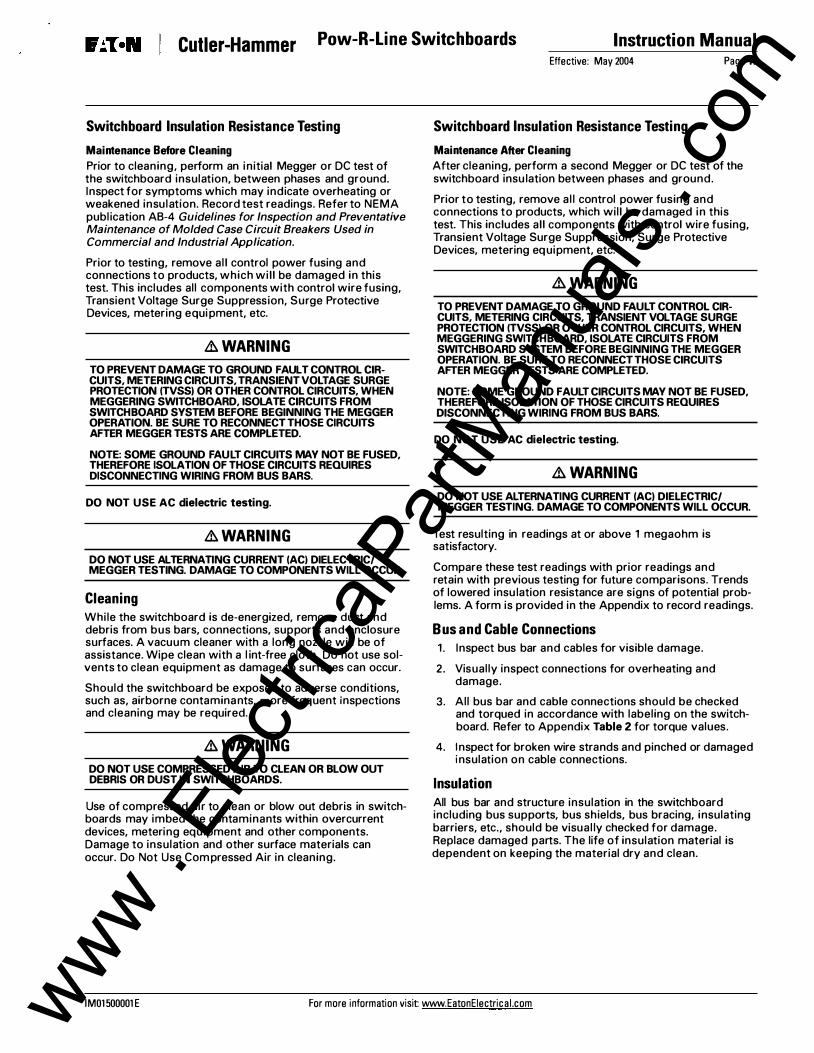
Prior to cleaning, perform an initial Megger or DC test of the switchboard insulation, between phases and ground. Inspect for symptoms which may indicate overheating or weakened insulation. Record test readings. Refer to NEMA publ ication AB-4 Guidelines for Inspection and Preventative Maintenance of Molded Case Circuit Breakers Used in Commercial and Industrial Application.
Prior to testing, remove al l control power fusing and connections to products, which wil l be damaged in this test. This includes all components with control wire fusing, Transient Voltage Surge Suppression, Surge Protective Devices, metering equipment, etc.
.&. WARNING
TO PREVENT DAMAGE TO GROUND FAULT CONTROL CIRCUITS, METERING CIRCUITS, TRANSIENT VOLTAGE SURGE PROTECTION (TVSSI OR OTHER CONTROL CIRCUITS, WHEN MEGGERING SWITCHBOARD, ISOLATE CIRCUITS FROM SWITCHBOARD SYSTEM BEFORE BEGINNING THE MEGGER OPERATION. BE SURE TO RECONNECT THOSE CIRCUITS AFTER MEGGER TESTS ARE COMPLETED.
NOTE: SOME GROUND FAULT CIRCUITS MAY NOT BE FUSED, THEREFORE ISOLATION OF THOSE CIRCUITS REQUIRES DISCONNECTING WIRING FROM BUS BARS.
DO NOT USE AC dielectric testing.
.&. WARNING
DO NOT USE ALTERNATING CURRENT (ACI DIELECTRIC/ MEGGER TESTING. DAMAGE TO COMPONENTS WILL OCCUR.
Cleaning While the switchboard is de-energized, remove dust and debris from bus bars, connections, supports and enclosure surfaces. A vacuum cleaner with a long nozzle will be of assistance. Wipe clean with a l int-free cloth. Do not use solvents to clean equipment as damage to surfaces can occur.
Should the switchboard be exposed to adverse conditions, such as, airborne contaminants, more frequent inspections and cleaning may be required.
.&. WARNING
DO NOT USE COMPRESSED AIR TO CLEAN OR BLOW OUT DEBRIS OR DUST IN SWITCHBOARDS.
Use of compressed air to clean or blow out debris in switchboards may imbed the contaminants within overcurrent devices, metering equipment and other components. Damage to insulation and other surface materials can occur. Do Not Use Compressed Air in cleaning.
Effective: May 2004 Page 17
Switchboard Insulation Resistance Testing
Maintenance After Cleaning
After cleaning, perform a second Megger or DC test of the switchboard insu lation between phases and ground.
Prior to testing, remove al l control power fusing and connections to products, which will be damaged in this test. This includes al l components with control wire fusing, Transient Voltage Surge Suppression, Surge Protective Devices, metering equipment, etc.
.&. WARNING
TO PREVENT DAMAGE TO GROUND FAULT CONTROL CIRCUITS, METERING CIRCUITS, TRANSIENT VOLTAGE SURGE PROTECTION (TVSSI OR OTHER CONTROL CIRCUITS, WHEN MEGGERING SWITCHBOARD, ISOLATE CIRCUITS FROM SWITCHBOARD SYSTEM BEFORE BEGINNING THE MEGGER OPERATION. BE SURE TO RECONNECT THOSE CIRCUITS AFTER MEGGER TESTS ARE COMPLETED.
NOTE: SOME GROUND FAULT CIRCUITS MAY NOT BE FUSED, THEREFORE ISOLATION OF THOSE CIRCUITS REQUIRES DISCONNECTING WIRING FROM BUS BARS.
DO NOT USE AC dielectric testing.
.&. WARNING
DO NOT USE ALTERNATING CURRENT (ACI DIELECTRIC/ MEGGER TESTING. DAMAGE TO COMPONENTS WILL OCCUR.
Test resulting in readings at or above 1 megaohm is satisfactory.
Compare these test readings with prior readings and retain with previous testing for future comparisons. Trends of lowered insu lation resistance are signs of potential problems. A form is provided in the Appendix to record readings.
Bus and Cable Connections 1. Inspect bus bar and cables for visible damage.
2. Visually inspect connections for overheating and damage.
3. All bus bar and cable connections should be checked and torqued in accordance with labeling on the switchboard. Refer to Appendix Table 2 for torque values .
4. Inspect for broken wire strands and pinched or damaged insulation on cable connections.
Insulation All bus bar and structure insulation in the switchboard including bus supports, bus shields, bus bracing, insulating barriers, etc., should be visual ly checked for damage. Replace damaged parts. The life of insulation material is dependent on keeping the material dry and clean.
IM01 500001 E For more information visit www.EatonEiectrical.com www . El
ectric
alPar
tMan
uals
. com
Instruction Manual Pow-R-Line Switchboards Cutler-Hammer Page 18 Effective: May 2004
Overcurrent Devices Ventilation Maintenance instructions and field-testing for overcurrent devices are included with the instruction leaflet for each device within a family. One instruction leaflet per frame or family type was included with this installation booklet inside the switchboard. Refer to the leaflet on each device. If leaflets are missing, contact Eaton for replacement.
Circuit Breakers
Visually inspect circuit breakers for signs of discoloration, cracking, scorching, overheating or broken parts. Exercise the breaker operating mechanism making sure it is opening and closing. A breaker showing signs of any one of these issues should be replaced. Refer to NEMA publication AB-4 Guidelines for Inspection and Preventative Maintenance of Molded Case Circuit Breakers Used in Commercial and Industrial Applications.
Fusible Overcurrent Devices
Visually inspect the switching mechanism and fuse connections. Visual ly inspect the fusible devices for signs of discoloration, cracking, scorching, overheating or broken parts. Replace any worn parts or the entire switch.
Fuse Replacement
& DANGER
HAZARDOUS VOLTAGE WILL CAUSE SEVERE INJURY OR DEATH. DE-ENERGIZE BOARD PRIOR TO SERVICING FUSIBLE DEVICES.
Be sure the switch mechanism is turned to the OFF position before attempting to remove fuses. Visually inspect the switch contacts, blades and mechanism to ensure that the mechanism is in the open/off position.
Check fuses to ensure that they are of the proper class, ampere, voltage and interrupting rating. Ensure that non-current l imiting fuses are not used as replacements for current l imiting fuses. Never attempt to defeat rejection mechanisms which are provided to prevent the installation of the incorrect class of fuse.
Meters, Controllers, Surge Equipment and Other Devices Individual devices should be maintained according to the specific instructions suppl ied for each device. Remove dust and dirt from exterior with a dry l int-free cloth. Un less specifical ly instructed in the individual device instruction leaflet, do not attempt to open sealed cases or containers.
& WARNING
NEVER USE COMPRESSED AIR TO CLEAN OR BLOW OUT DEBRIS OR DUST IN SWITCHBOARDS.
Secondary Wiring Check al l wiring connections for tightness, including those at the current and potential transformers, if present, and at al l terminal blocks. Check al l secondary wiring connections to ensure they are properly connected to the switchboard ground bus, where indicated. Look for broken wire strands and pinched or damaged insulation.
Check al l grills and ventilation ports for obstructions and accumulations of dirt. Clean ventilation ports, if necessary. For switchboards installed outdoors, inspect the air space under the switchboard to be sure that it is clean and clear of debris, leaves and obstructions.
Records It is essential to maintain the equipment in satisfactory condition.
Mainta in a permanent record of all maintenance activities and testing for future reference. (See Appendix B.)
The condition of each switchboard should be recorded as a guide for anticipating the need for any replacement parts or components or special attention at the next regular maintenance period. It is recommended that a series of inspections be made at quarterly intervals until the progressive effects of local conditions can be analyzed to determine a regular schedule.
Switchboard Events and Service Interruptions
Short Circuits, Ground Faults and Overloads
&WARNING
DO NOT ATTEMPT TO RE-ENERGIZE SWITCHBOARD OVERCURRENT DEVICES AFTER ELECTRICAL EVENTS, SUCH AS SHORT CIRCUITS, GROUND FAULTS AND OVERLOADS, UNTIL THE CAUSE OF THE EVENT HAS BEEN IDENTIFIED AND CORRECTED.
A thorough assessment, identification and correction of the event origin must be completed. An additional assessment of the conductor insulation and other insulating materials should be made. Replace all damaged insulation materials, conductors and overcurrent devices. Original switchboard parts, insulators, insulation material and overcurrent devices must be replaced with renewal parts from Eaton. (See Renewal Parts Page 19.)
Do not attempt to re-energize switchboard overcurrent components after electrical events, such as short circuits, ground faults and overloads, until the cause of the event has been identified and corrected.
After the event has been rectified, test equ ipment per the maintenance process described in this publication.
Physical Damage
Any physical damage to the switchboard that occurs after the switchboard is installed must be corrected. A thorough inspection, which includes the exterior enclosure and deadfront, plus interior components in the damaged portion of the switchboard, should be conducted. Replace all damaged parts and components. Ensure that there are no gaps in the switchboard enclosure that could cause exposure to live parts. Contact Eaton for renewal parts and assistance.
After the physical damage has been corrected, test equipment per the maintenance process described in this publ ication.
For more information visit: www.EatonEiectrical.com IM01500001E www . El
WET SWITCHBOARDS PRESENT A HAZARDOUS CONDITION AND MAY CAUSE INJURY OR DEATH. DE-ENERGIZE POWER TO ALL EQUIPMENT BEFORE SERVICING.
DO NOT WORK ON SURFACES OR FLOORS WHERE THERE IS STANDING WATER.
& DANGER
DO NOT WORK ON SWITCHBOARDS OR ENTER AREAS THAT HAVE STANDING WATER. DE-ENERGIZE ALL EQUIPMENT IN AREAS WITH STANDING WATER.
DO NOT WORK ON WET ENERGIZED ELECTRICAL EQUIPMENT.
Major accumulation of water or moisture on any part of the switchboard can cause catastrophic damage to the switchboard. If a switchboard has been submerged by more than 2 inches or where running or standing water has had contact with current carrying parts, it has sustained significant damage.
& WARNING
SWITCHBOARD COMPONENTS, INCLUDING CIRCUIT BREAKERS, FUSIBLE SWITCHES, METERING, ETC., SUBJECTED TO WATER OR MOISTURE MAY BE RENDERED UNSAFE. REPLACEMENT IS REQUIRED.
The switchboard and its components may be damaged beyond repair and may need replacement.
1. Do not attempt to clean or repair water damaged equipment or components.
2. De-energize the switchboard at its source.
3. Do not energize.
4. Contact Eaton for replacement.
Minor accumulations of moisture, such as condensation, over a short period of time may be corrected using heat.
De-energize switchboard.
Apply approximately 250 watts per vertical section for a sufficient period of time until the moisture disappears, then remove all heat sources and materials used for drying.
Inspect for damage to components and any corrosion. If any damage or corrosion is present, contact Eaton. DO NOT RE-ENERGIZE SWITCHBOARD.
After the switchboard has completely dried, remove al l materials and tools from the equipment. Inspect al l connections for damage and torque. Re-install all covers, fi l lers, deadfront assemblies and side sheets. Conduct switchboard insulation resistance testing described in this publication.
Effective: May 2004 Page 19
Renewal Parts Switchboards can be complex assemblies with unique parts to fit the specific appl ication and need. The manufacturer offers expertise with renewal part identification. To ensure safety and to maintain UL listing, it is essential that only new parts and components from Eaton be utilized.
When ordering renewal parts or when requesting information on the switchboard, it is essential to include as much information as possible.
Each switchboard will have a nameplate and other identification marks with details that will help expedite information requests and orders. The following may be required to help identify parts and information requests.
• GO or General Order N umber
• Item number
• Description of the equipment
• Supply voltage
• Equipment ratings
• Catalog number or style number of part, if available
• Description of the part
• Drawing numbers
• Rating of part(s)
Electrical distribution equipment has a l imited life span. As such, the manufacturer cannot guarantee the avai labil ity of obsolete equipment or parts. Equipment replacement may be recommended.
IM01500001E For more information visit www.EatonEiectrical.com www . El
ectric
alPar
tMan
uals
. com
Instruction Manual
Page 20
Appendix
Appendix A
Effective: May 2004
Table 2. Torque Values for Copper or Aluminum Bus Bar Connections
I Bolt Size I Torque Inch Lbs I Torque Foot Lbs I #10 30 Inch Lbs. 2.5 Foot Lbs. 1/4" 65 1nch Lbs. 5.4 Foot Lbs. 5/16" 130 Inch Lbs. 10.8 Foot Lbs. 3/8" 240 Inch Lbs. 20.0 Foot Lbs. 1/2" 600 Inch Lbs. 50.0 Foot Lbs.
Note: For other torque values, refer to instruction leaflet for the specific component.
Pow-R-Line Switchboards Cutler-Hammer
Appendix B
Switchboard Maintenance, Testing and Inspection logs
Refer to Maintenance section of this document on Page 16 for detailed information.
& DANGER
HAZARDOUS VOLTAGE WILL CAUSE SEVERE INJURY O R DEATH. DE-ENERGIZE BOARD PRIOR TO SERVICING FUSIBLE DEVICES ONLY "QUALIFIED PERSONS" SHOULD INSTALL AND OR SERVICE THIS EQUIPMENT.
&WARNING
TO PREVENT DAMAGE TO GROUND FAULT CONTROL CIRCUITS, METERING CIRCUITS, TRANSIENT VOLTAGE SURGE PROTECTION (TVSS) OR OTHER CONTROL CIRCUITS, WHEN MEGGERING SWITCHBOARD, ISOLATE CIRCUITS FROM SWITCHBOARD SYSTEM BEFORE BEGINNING THE MEGGER OPERATION. BE SURE TO RECONNECT THOSE CIRCUITS AFTER MEGGER TESTS ARE COMPLETED.
NOTE: SOME GROUND FAULT CIRCUITS MAY NOT BE FUSED, THEREFORE ISOLATION OF THOSE CIRCUITS REQUIRES DISCONNECTING WIRING FROM BUS BARS.
& WARNING
DO NOT USE ALTERNATING CURRENT lAC) DIELECTRIC/ MEGGER TESTING. DAMAGE TO COMPONENTS WILL OCCUR.
For more information visit www.EatonEiectrical.com IM01500001E www . El
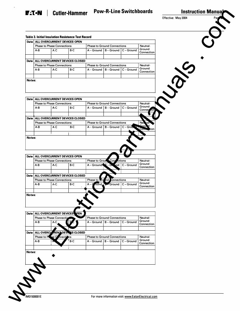
Table 3. Initial Insulation Resistance Test Record
Date ALL OVERCURRENT DEVICES OPEN
Phase to Phase Connections Phase to Ground Connections Neutral-A-8 l A-C I 8-C A - Ground I 8 - Ground I C - Ground Ground
Connection
I I I I Date ALL OVERCURRENT DEVICES CLOSED
Phase to Phase Connections Phase to Ground Connections Neutral-A-8 l A-C I 8-C A - Ground I 8 - Ground I C - Ground Ground
Connection
I I I I Notes:
Date ALL OVERCURRENT DEVICES OPEN
Phase to Phase Connections Phase to Ground Connections Neutral-A-8 � A-C I 8-C A - Ground I 8 - Ground I C - Ground Ground
Connection
I I I I Date ALL OVERCURRENT DEVICES CLOSED
Phase to Phase Connections Phase to Ground Connections Neutral-A-8 � A-C I 8-C A - Ground I 8 - Ground I C - Ground Ground
Connection
I I I I Notes:
Date ALL OVERCURRENT DEVICES OPEN
Phase to Phase Connections Phase to Ground Connections Neutral-A-8 l A-C I 8-C A - Ground I 8 - Ground I C - Ground Ground
Connection
I I I I Date ALL OVERCURRENT DEVICES CLOSED
Phase to Phase Connections Phase to Ground Connections Neutral-A-8 l A-C I 8-C A - Ground I 8 - Ground I C - Ground Ground
Connection
I I I I Notes:
Date ALL OVERCURRENT DEVICES OPEN
Phase to Phase Connections Phase to Ground Connections Neutral-A-8 l A-C I 8-C A - Ground I 8 - Ground I C - Ground Ground
Connection I I I I
Date ALL OVERCURRENT DEVICES CLOSED
Phase to Phase Connections Phase to Ground Connections Neutral-A-8 � A-C I 8-C A - Ground I 8 - Ground I C - Ground Ground
Connection
I I I I Notes:
IM01500001E For more information visit www.EatonEiectrical.com www . El
ectric
alPar
tMan
uals
. com
Instruction Manual Pow-R-Line Switchboards
Page 22 Effective: May 2004
Table 4. Switchboard Inspection Log
I Date I Check List
Cleaning Bus and Cable Connections Insulation Inspection Overcurrent Device Inspection Meters Controllers Surge Protective Devices Other Protective Devices Secondary/Control Wiring Clean Ventilation
I Date I Check List
Cleaning Bus and Cable Connections Insulation Inspection Overcurrent Device Inspection Meters Controllers Surge Protective Devices Other Protective Devices Secondary/Control Wiring Clean Ventilation
I Date I Check List
Cleaning Bus and Cable Connections Insulation Inspection Overcurrent Device Inspection Meters Controllers Surge Protective Devices Other Protective Devices Secondary/Control Wiring Clean Ventilation
./ I Notes and Actions Taken
./ I Notes and Actions Taken
./ I Notes and Actions Taken
Note: Refer to Mai ntenance section on Page 16.
For more information visit: www.EatonEiectrical.com
Cutler-Hammer
N ational E lectrical Code and NEC are registered trademarks of the National Fire Protection Association, Quincy, Mass. U L is a federally registered trademark of Underwriters Laboratories I nc. N E MA is the registered trademark and service mark of the National Electrical Manufacturers Association. Cutler-Hammer and Pow-R-Une are federal ly registered trademarks of Eaton Corporation.
IM01500001E www . El
ectric
alPar
tMan
uals
. com
Cutler-Hammer
Notes
IM01500001 E
Pow-R-Line Switchboards . .
For more information visit: www.EatonEiectrical.com
Instruction Manual
Effective: May 2004 Page 23 www .
Elec
tricalP
artM
anua
ls . c
om
Instruction Manual Pow-R-Line Switchboards
Page 24 Effective: May 2004 I . �
Notes
Eaton Electrical Inc. 1000 Cherrington Parkway Moon Township, PA 15108-4312 USA tel: 1-800-525-2000 www.EatonEiectrical.com