C U T S 1 M - K C O M P U T E R P R O G R A M F OR OPTIMUM CUTTING DRUM DESIGN Yehuda Anar A dissertation submitted to the Faculty of Engineering, Univ -rsity of the Witwatersrand, Johannesburg, in fulfilment of the requirements for tha degree of Master of Science in Engineering. Johannesburg, 198R
Transcript
C U T S 1 M - K C O M P U T E R P R O G R A M F O R O P T I M U M C U T T I N G D R U M D E S I G N
Yehuda Anar
A dissertation submitted to the Faculty of Engineering, Univ -rsity of the Witwatersrand, Johannesburg, in fulfilment of the requirements for tha degree of Master of Science in Engineering.
Johannesburg, 198R
DECLARATION
I d e clare that this d i s s e r t a t i o n is my own, u n aided v being s ubmitted for the Degr e e of M a s t e r of S c ience : in the Unive r s i t y of the W i t w a t e r s r a n d , J o h a n n e s b u r g been subm i t t e d before for any d e g r e e or e x a m i n a t i o n j University.
(Signature of candidate)
i o r k . It is in En g i n e e r i n g
It has not in any other
(ixi)
ABSTRACT
To date*, - ... t <.-. of coal cutting machines have designedcutter drub.- w> '.houf considering the needs of the individual collieries. Different coal seams and product -ize requirement have in general not been assessed. The use of the COTSIM program will enable colliery engineers and the manufacturers of continuous miner and longwalI shearer to analyse the effect of various pick lacings and select the one most suitable for their cutting c o n d itions. The literature indicates that this approach of simulating and analysing the performance of a cutting drum via the computer has been done previously- However no report is publicly available for converting the first simulating program into a working tool for drum design. This report describes the development of the CUTSIM program and details how the progress was validated successfully against the findings of three different areas of w o r k :
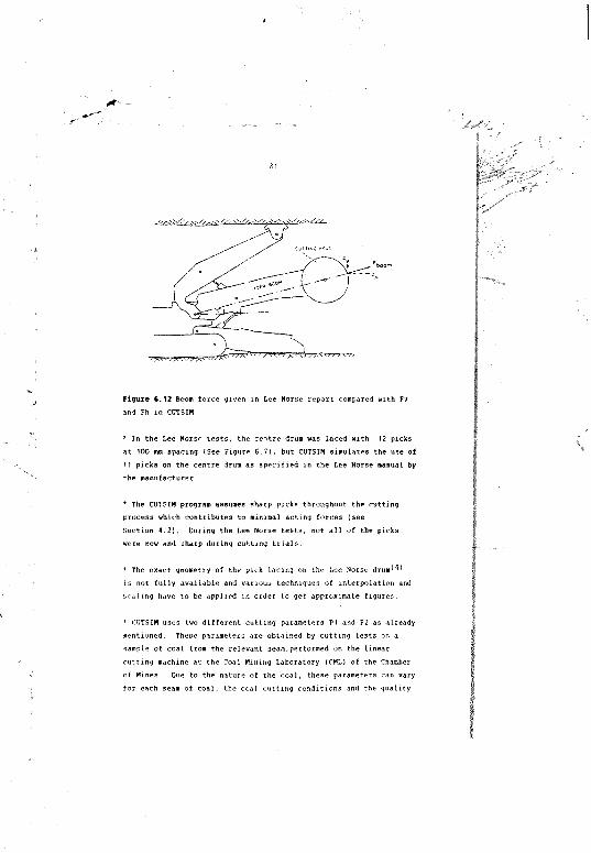
* manual calculations made for the same dium lacing* previous work performed on the !,pe Norse experimental continuous
miner in the early 1980's* results of field testing of pick lacings indicated by CUTSIM.
Various examples of using CUTSIM efficiently in order to obtain a better cutting performance are attached as a demonstration of the potential of CUTSIM,
The program is considered a valuable design tool for the local manufacture of continuous miners and longwal1 shearer and is currently being used by the coal industry successfully.
It is shown that with the aid of jomputer simulations of a continuous miner that an inefficient cutting drum laced with 110 picks can be modified to a lacing of only 66 picks, with «» significant cutting im p ro v em e n t The use of CUTSIM for better drum
(IV)
design or for redesigning ol an existing drum is very inexpensive. Ho additional machinery or instrumentation are r e q uired. For comprehensive analysis, the required data input are the geometry of the cutting drum, a sample of coal block and one of tne p.cks which the drum is laced w i t h .
In memory of my mother Rachel Asar 1929 - 1970
ACKNOWLEDGEMENTS
The Chamber of Mines of Scith Africa Research Organization has allowed the use of facilities and resources, and permission to publish data, without which this dissertation would not have been possible.
The expert advice of Professor H.R. Phillips has been an inspiration in the completion of this dissertation.
I would like to thank the management and staff at all the collieries visited for their co-operation and help in carrying out the t e s t s .
I wish to express my thanks to Joy Manufacturing for their assistance and to the various pick manufacturers.
The support and understanding of my wife and my daughter during the documentation of this study has played an important part in its completion.
DECLARATIONABSTRACTACKNOVLEDGEMEMTSCONTENTSLIST OF FIGURESLIST OF TABLESLIST OF SYMBOLS
aiiivi
viiix
xivx w
INTRODUCTION
1.1 General Energy Source Consideration1.2 Mining Methods1.3 Common Problems with Existing Equif/eent1.4 Economical Forecast1.5 Potential Benefits
2 COAL CUTTING THEORY
2.1 The Cutting Process2.2 Pick Condition and Geometry2.3 Interaction of Cutter Picks in Array2.4 Various Mathematical Models of Rock Cutting
DEFINITION OF APPLICATIONS
.'ICR CUTTING PROFILE FOR CUTSIM
3.13.1.13.1.2
Numerical ModelCutting parameter Cutting forces
COMPUTER MODEL
132021
2326
4.1 Advantages of Simulated Numerical Model4.2 Description of Model Used4.3 Drum Layout4.4 Mineral Properties
5 APPLICATION OF COMPUTER MODEL
5.1 Numerical Simulation of Various Mining Conditions5.2 Pick Lacing of the Drum5.3 Cutting Conditions5.4 Cutting Profile of the Drum5.5 Analysis of Continuous Miner Forces and Torque5.6 Cornei Cutting Drum Design5.7 Simulation of a Cutting Drum with Ripperveyor
34353637
34414244525560
VALIDATION OF FINDINGS
fe.1 Validation against Manually Calculated Forces6.2 Comparison of CUTSIM with Lee Norse Findings6.3 Experimental Underground Tests
6774
7 CONCLUSIONS
APPENDICES
APPENDIX A
APPENDIX B
APPENDIX C
APPENDIX D
APPENDIX E
APPENDIX F
APPENDIX G
APPENDIX H
APPENDIX I
APPENDIX J
APPENDIX K
DESCRIPTION OF COAL SAMPLES FOR CUTTING TESTS
DESCRIPTION OF EXPERIMENTAL EQUIPMENT AND TECHNIQUE
SIMULATION OF CORNER CUTTING
DESCRIPTION OF PICK CONDITIONS
PARAMETERS Pi AND P2 AS AFFECTED BY VARIOUS CUTTING CONDITIONS
MANUAL CALCULATION OF FORCES AND TORQUE
TABULATED RESULTS OF LABORATORY COAL CUTTING
LACING PATTERNS USED AT LEE NORSE TESTS
CL'TSIM SIMULATION OUTPUT OF l EE NORSE PICK LACINGS
UNDERGROUND TESTS IN NEW DENMARK COLLIERY AND SUBSEQUENT CUTSIM SIMULATIONS
FLOWCHART OF ACTIVITIES FOR USING CUTSIM
REFERENCES
**' -
LIST OF FIC0SES
Figure
1 . 1
1 . 2
1 ,1
1. 4
2 . 1
2.2
2.3
2 .4
2.5
2.6
2.7
2.8
2.9
2 . 1 0
2 . 1 1
3 . 1
3.2
3.3
Annual oxi I production and employment for the South African coal industry
Historic! summary of m i n i n g m e thods in Sou t h Africa
Contin u o u s miner, ripperveyor type
Longwall shearer
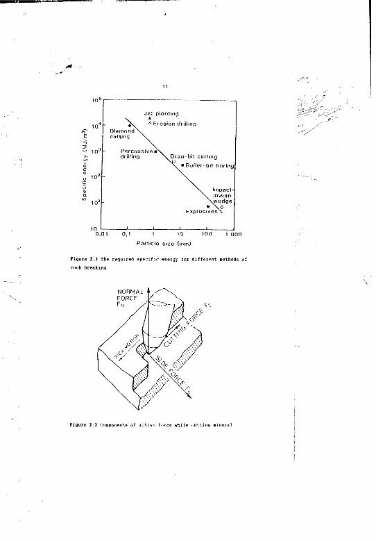
The required s p ecific e n ergy for d i f f e r e n t methods of rock b r eaking
Components of a c t i v e force w h ile c u tting m i neral
Typical c u tting forces d i a g r a m when c u t t i n g coal
Typical ana l o g u e of pick forces v e rsus d i s t a n c e cut
Sieve a n alysis results s h owing c u m u l a t i v e w e i g h t per cent as a f unction of rock p a rticle size
Geometry of a pick w h ile cu t t i n g mineral
The basic rela t i o n s h i p for cu t t i n g coal wi t h pick
Hy p o t hetical rel a t i o n s h i p b e tween pick s p acing and specific e n ergy
Interaction of c u tter picks in array
Corner cu t t i n g pick : ituations
Pick force a g a i n s t DOC at various c u t t i n g speeds wilh jet-at-pi c k - f a c e assis t a n c e
Coal c u tting pr ofile wi t h a straight pick
Coal cutting p r o f i l e with a 30® skewed pick
Coal cutting profile
Coal cutting profile
Components of a c t i v e force w h ile c u tting .mineral
ompononts of the totalDirection of the thr cutting force
The depth of cut contact
The total c u tting fore
the angle
11
12
12
14
14
15
17
17
18
\
29
30
* --
(X)
LIST OF FIGURES
Figure
3.9 R e s o l u t i o n of total c u t t i n g f o r e into two d i f f e r e n t sets of components
4.1 T h e c ylindrical s y stem of the d r u m and the global
4.2 Blo c k of mineral, in a g l o b a ’ co- o r d i n a t e d s y stem
4.3 Dire c t i o n of c u tting in mineral with a large number of bands
5.1 Sche m a t i c of a skew a n g l e pick box
5.2 Pi c k lacing on solid d r u m : Joy 14CM 9
5.3 T h e breakout p r ofile o b t a i n e d by using Z i n c r e me n t - 1
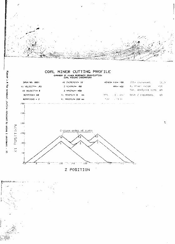
5.4 T h e breakout p r ofile obt a i n e d by using 1 i n c r e m e n t - io
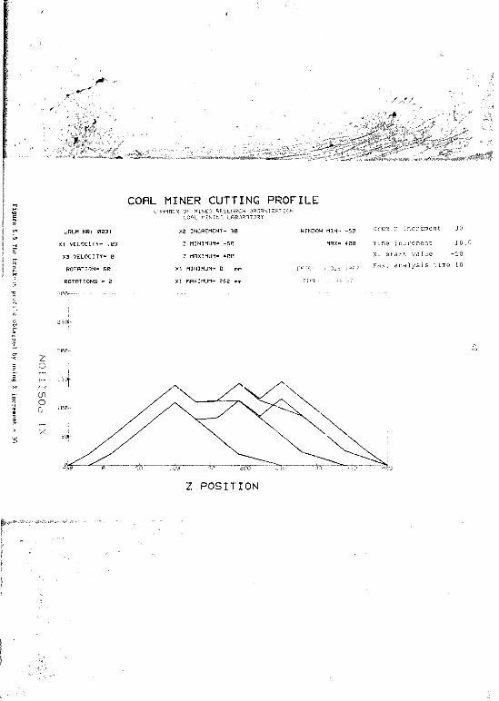
5.5 The breakout p r ofile o b t a i n e d by using Z i n c r e m e n t - 30
5.6 Zooming the br e a k o u t profile
",.7 T h e breako.t p r ofile obt a i n e d by using 'quick p l o t 1
5.9 The breakout p r o f i l e p l o t t e d w i t h o u t any m a rking numbers
5." T h e breakout p r ofile of J o y 14CM 9 c ontinuousminer
5.10 Enlargement of the left hand s e ction of Joy 14CM 9 drum
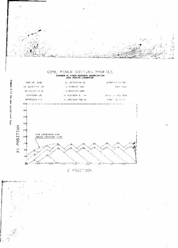
5.11 T h e new curved coal face
5.12 T h e new breakout p r ofile of the w h ole drum
5.13 T h e pick lacing of r i p p e r v e y o r :Joy 12HM 9
5.14 The breakout profile of r i p p e r v e y o r :Joy 12HM 9
5.15 The enlarged breakout p r o f i 1" of one section ofJ o y 12MM 9
6 1 Tlv' lacing pattern of the test drum
6.2 The lacing pattern of thr test drum
Page
31
3'
38
38
41
43
45
47
48
51
52
54
5''
58
LIST OF FIGURES
Figure
6.3 The cutting forces and toijue of the test drum
6 . -1 Pick position for 1 1 = 10"
6.5 Pick position for 1 1 = 55" and 82-15°
6.6 Manual calculation of forces and torque
6.7 The lacing patterns for various spacings used with the Lee Norse drum
6.9 Comparison of Lee Norse Boom forces and CUTSIM norma) f o r e s - suraping mode
6.9 Comparison of Lee Noise Boom forces and CUTSIM normal forces - shear mode
6.10 Comparison of Lee Norse anu CUTSIM torque
6.11 Comparison of Lee Norse and CUTSIM torque
6.12 Boom force given in Lee Norse report compared with Fv and Fh in C U T S I M
age
70
80
80
B3
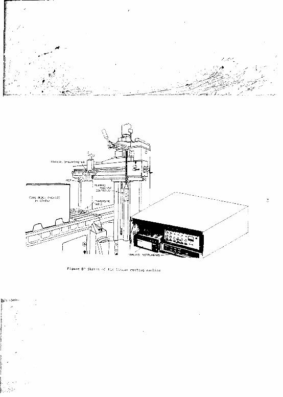
Sk etch of the linear c u t t i n g m a chine
S k etch of the po s i t i o n of the dy n a m o m e t e r i linear cutting machine
Photo g r a p h of the C U T S I M pi c k h o lders for v a r i o u s sk e w angles
Ci The acting force? and torque
C2 The acting forces and torq u e on the original dr u m
C3 The acti n g forces and torq u e
C4 The acting forces and torque
the original d r u m
i the p r oposed dr u m
. the p r oposed d r u m
The pick class of five Sandvik button picks
Various wear p r ofiles of F agersta point a t t a c k pick showing the a v e r a g e mass loss of the piofil** 100
Va r i o u s pick j; ha pep 101
C o m p a r i s o n of variou.. „ k.-w -mgh- picks 102
(xii)
LIST OF PIGMIES
Figure
H 1 Va r i o u s pick holder:; u?^‘d at Lee Nor s e trstr,
H? Pick lacing p a ttern for 50 mm spacing
Hi Pick lacing pattern for 100 mm spacing
H4 Pick lacing paltprn for ISO mm spacing
H‘, Pick lacing p a ttern for 200 mm spacing
11 CUTSIK s imulation of L M »or„ drum
12 CUTSIM s imulation of Norse: d r u m
n COTSIl - iituilation of Lee Norse dr jib
M COTSIM simulation of L«c No r s e
CUTSIM s imulation of Lfr Nomp
16 CUTSIM simul a t i o n of No rse
17 CU iSIM •simulation of Norac dru m
18 CU TSIM s imulation of Nor s e drum
J1 The lacing of the test. dr u m usi n g R0 picks
1 2 The cut ting profile cl the 60 picks drum
.13 The forces acting and torqur on the bO picks
J4 Thr fnrcer a c ting and torque on the 80 picks
Th#- lacing of the Les* dru m u sing 67 pick;.
The cutting profile of thc(7 Pii-kc d:u»
.17 The rorc-rj acti n g and torque on the i I picks drum
J P The forte: acting and torque on the 6 7 picks dru.
J9 The lacing of the test sing 69 picks
,! *0 The cutting profile of picks dtum
.; 11 The [vr,e: acting and tor'iiif on the 69 picks dru.
J12 Thr f otcer, a cti n g and torque 'ui. the b9 picks d r urn
Page
113
114
115
116
117
119
120
121
122
123
124
125
12C
131
132
133
134
135
136
137
133
1 31
140
141
142
(%iii)
LIST OF FIGURES
Figure Page
J 1 3 The lacing of the test drum using 65 picks 143
J14 The cutting profile of the 65 picks drum 144
J15 The forces acting and torque on the 65 picks drum 145
J15 The forces acting and torque on the 65 picks drum 146
J17 Joy test drum using 110 picks 147
J18 Joy test drum using 98 picks 148
J19 Joy test drum using 80 picks 149
J20 Joy test drum using 66 picks 150
K1 Flowchart of activities for running CUTSIM 152
(xiv)
LIST OF TABLES
Table Page
1.1 Overview of world coal mining situation in 1985 2
1.2 Production figures for South African coal mines 7
5.1 Tabulation of pick patterns 42
5.2 Cutting conditions for analysis 44
5.3 The required data for the breakout p r o f i l e of adrum 49
5.4 Pick radii of the corner cutters 59
5.5 Comparison of forces and torque for original andproposed lacing 60
6.1 Pick lacing data of the test drum 68
6.2 Lee Norse : CtiTSIM generated normal forces andtorques 7/
6.3 Lee Norse : measured boom forces and druatorques 77
6.4 Results of lacing pattern tests and relatedforces and torque for shearing mode 83
6.5 Results of lacing pattern tests and relatedforces and torque for sumping mode 83
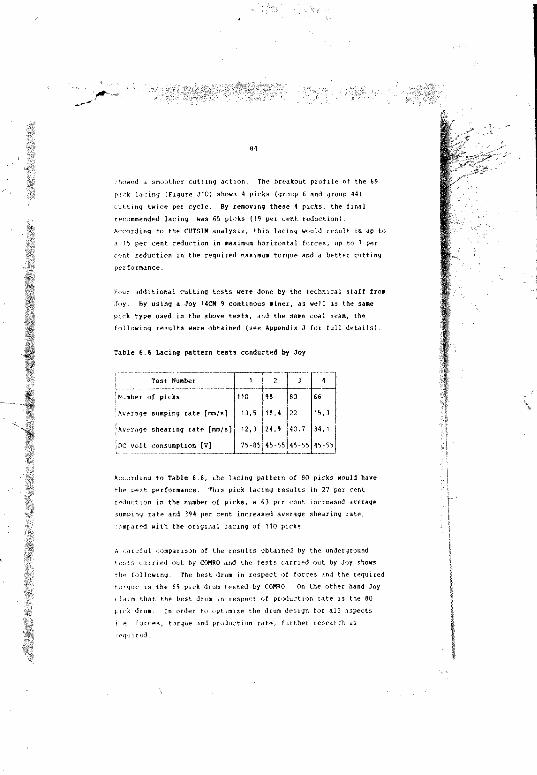
6.6 Lacing pattern tests conducted by Joy 84
El The cutting parameters P 1 and P2 for various pickmass losses 103
E2 The cutting parameters PI and P2 for various coalseams 104
E3 The cutting parameters PI and P2 for various pickshapes 104
E4 The cutting parameters PI and V? as affected bywater ]ot assisted cutting 104
E5 The cutting parameters P1 and P2 for various skewangles 106
FI Manual valcul ition of forces for test drum inshearing mode 107
LIST OF TABLES
Table Page
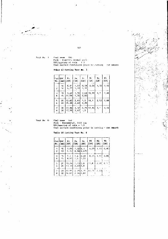
01 Guttiug No. 1 108
G2 Cutt 3ng test No. 2 108
G3 Cutting test No. 3 109
G* Cutting test No. 4 109
G5 Cutting test No. 5 110
GG Cutting test Ho. 6 110
G? Cutting test Mo.7 111
Ji Cutting test using 110 Picks 129
J2 Cutting tes» using 98 picks 129
J3 Cutting tost using 80 pirxs 130
J4 Cutting test using 66 Picks 130
H ST OF SfflPPM
S'-mbol Quantity Unit
DOC Depth of cut mm
Fc Cutting force kN
Fn Normal force kN
Fs Side force kN
P1 Cutting parameter
P2 Cutting parameter kN/mm
Fc Total cutting force kN
e Attack angle of the pick degree
Skew angle of the pick degree
8 Angle of pick position degree
Z Co-ordinate of pick positionalong the drum mm
r Cutting radius of the pick mm
XI Forward drum velocity m/s
X2 Sideway drum velocity m/s
XI Vertical drum velocity m/s
1 increment Axial resolution mm
X ■ ta11 value Initial position of the drumin relation to the coal face mm
Z range minimum Initial range along the drum mm
Z range maximum Final range along the drum mm
Fh Horizontal force kN
r\ V e r t i c a l force kN
i Angle between Ft and Fh degree
p Angle between Ft and Fn degree
K Linear factor(gradient) kN/mm
T T o r q u e k N ‘m
(xvii)
l i s t o f s i m o i s
Symbol Quantity Unit
N u m b e r of D r u m re v o l u t i o n s per m i n u t e r/min
f b r eakout an le d e g r e e
F! S p ecific e n e r g y MJ/ m ^ ( MJ/kC
CHAPTER 1 IHTROOOCTION
This thesis deals with a method of coal cutting by means of picks on a rotating drum. The technique investigated is the use of a computer program for simulating the coal cutting process and analysis of the related forces and torque. These applications can be used either for assessing the lacing pattern of an existing cutting drum and proposing the changes required or for a new design of a cutting drum. It is vital that production methods are improved and the related cost reduced in view of the present difficult conditions for South Africa in the world market due to:
* The recent drop in coal prices world wide resulting in closing of a number of collieries
* due to the political situation, the South African coal is more than ever before an unwanted product overseas
* increased labour cost makes the coal production too expensive for the collieries. 4
1.1 General Energy Source Consideration
South Africa is fortunate to have an enormous amount of coal estimated at 51 Gt (51 x 109 ton) reserves and 110 Gt of resources as reported in the Petrick report in 1975 and updated in 1981.These findings are also supported by Bright, 1958(Z The coal (as raw coal or synthesized into liquid fuel at the various SASOL plants) provides an estimated 25 to 50 per cent of the naliona) energy requirements. Since the turn of the century coal production increased gradually to reach 50 million tons in the 1963's. Following a brief stagnation in the late 1 9 6 0 s and early !970's, the coal product on increased at an annual growth rate of about 10 per cent to reach more than 168 million tons in 1986, see Figure 1.1. South Africa is now the 5th largest hard coal producer and the third largest coal exporter in the world, as shown in
1.1. Cook, 1*170)
r
200
Annual coal production
Persons employed in the coal industry150
,1E
100
50
*20 *30 *40 'SO *60 '70 '80 *90 20001900 *10
Figure 1.1 Annual cual production and employment for the South African coal industry
Table 1.1 OVERVIEW OF WORLD COAL MINING SITUATION IN 198b
The main reasons for the exception! growth of the coal mining industry during the past 15 years were a massive increase in electric power generating capacity to meet the longer term needs of the country, the political events in Iran which have threatened the supply of oil to South Africa and the increased world demand for coal following the energy crisis in the late 1970's.
The rapid growth rate of the South African coal industry was facilitated by a well developed infrastructure, an organized and economically-strong mining industry, and most importantly, favourable geological conditions and ample labour resources.
1.2 Mining Methods
Figure 1,2 gives a histor^.al surmary of the various mining methods that are in use in South African collieries. Two important trends emerge from this figure. Firstly, the labour intensive hand-loading method of bord and pillar mining which was employed almost exclusively before 1965, has been replaced by the mechanized method of bord and pillar m W ' g where coal is merha- ; .ally loaded into shuttlecars and transported to the sect on ueii.. More recently the bord and pillar method of mining has been mechanized further by the introduction of drum-type continuous miners (Figure 1.3) which replace drilling anu blasting. Secondly, the opencast method of mining has grown in importance since 1970 and by 1986 accounted for about one third of the total coal production Finally, a number of longwall faces have been installed since 1970 and although this method of mining accounts for less than 10 per cent of the total annual coal production, it is likely to increase in importance.
Figure 1.2 shows .iso that by mid 1988, the forecasted total coal production obtained by continuous miners (Figure 1.3) and longwall shearers (Figure 1.4) will be about 3!> million cons or 20 per cent of the total coal production in South Africa.
Pro
duct
ion
(mill
ions
o(
sa
les
tonn
es
per
ye
ar)
r ..■
180 -IL on gw a llA c tu a l
f o re c a s t160
O p e n ca s t140 -
120 -
100 -
80 -
6 0 -
P illa r(m ech an ise d
lo a d e rs )
'70 '80 '9085565
/
P o rio d (y e a rs )
Figure 1.7 nisi rial nummary of mining mmth
CUTTING DRUM
BOOM
SLEWING CONVEYOR DISCHARGE RIPPERVEYOR
BOOM JACKS CENTRAL CONVEYOR
^ GATHERING ARMS
OPERATOR’SPOSITION
CAT'TRACKS
Figure 1.3 Continuous m i n e r , tipperveyot type
CUTTING DRUM
COWL
RANGINGARM"
' MACHINE CHASSIS CONTAINING MOTORS, /HYDRAULIC PUMPS A GEAR-. BOXES
Figure 1.4 Longwall shcar.-r
Table 1,2 shows the 198-' total, production figures for South African coal m i n e s . The total coal production obtained by bord and pillar and stooping with continuous miners and longwall shearers was 41,1 million tons, or 24 per cent of the total c a 2 production.
According to the Government Mining Engineer ( 1 9 8 6 ) ^ there are presently 135 continuous miners in use in mechanized bord and pillar mining, pillar extraction and longwall development. In addition more than 1 000 shuttlecazv are in use in underground collieries to transport coal from the corking face to the section conveyor belts.
Over the past ten years a total of twelve longwall faces have been introduced in South African c o l l i e r i e s . The longwall equipment used in moderately thick coal seams is among the most modern equipment found anywhere in the w o r l d . The extremely hard coal has made it necessary to develop extra powerful double drum shearer loaders for local longwall faces. The power rating of these shearers is frequently in excess of 1 000 kw and has set new power ratings records for this type of equipment.
1.3 Common Problems with Existing Equipment
The most common problems experienced by existing cutting drums a r c
* Overlaced drum which is unable to penetrate the mineral. The total thrust applied by the cutting machine divided by the number of picks in contact with tne coal face is the thrust per p. ck for that depth of cut. A large number of cutting picks tends to reduce the thrust, per u c k which will result in a poor penetration rate.
* Uneven sequence of cutting which results in excessive vibration. The designer of a cutting drum should aim for a pick lacing which will result as far as possible in an even force and torque output during one complete revolution of the drum. The pick l a c in g should result jn minimum forte and torque cycles for one revolution in order to m in im iz e the vibration acting on th e machine
Table 1.2 Production figures for South African coal mines
* Coal core geneiation due to a wide pick spacing between the drum sections. The existing pick lacing used by various continucus miners manufacturers leaves about 130 mm space between the adjacent picks in two drum sections (see Figure 5.15). This results in a build up of coal core which often is not broken by the coal breaker located between the drum sections. This coal cere generates much of the vibrations on the cutting machine.
* Small product size which contributes to an increased generation of airborne coal dust and fines production. The over laced drum which has a poor penetrat.on rate, tends to produce small coal
1.4 Economical Forecast
The computer simulation and cutting analysis detailed in this thesis can be applied to continuous miners, longwall shearers or any coal cutting machine which cuts with a rotating drum Assuming that using the recommended pick lacing obtained by this computer simulation wi.ll result in 10 per cent increased production of the abovementioned machinery, a significant reduction in cost should r e sult. The present price obtained overseas for South African coal is about U.S. $30 per t o n . This means that extra annual income of 123 million U.S. $ could be gained by the coal industry {using the 1986 production figures). No additional investment is required in order to achieve this goal and all indications show that the total benefit could be even g r e a t e r .
1.5 Potential Benefits
As far as can be determined from the literature, concerning the coal mining industry, computer programs for simulating continuous miner drums have been written previously. However this work is not read.' ly available as no report was written. Therefore there is a need for such research work in order to convert such a program o a working tool for drum design.
/ * '
9
The potential benefits whin, will result froui the use of such an assessment- are:
1. a faster mining rate of advance
2. reduced operating costs (ie. less pick replacements)
3. extension of the life of the machine due to less vibration during a cutting cycle
4. improved si and health by reducing the amount of respirable coal dust i . m e atmosphere
5. larger product size.
In the thesis, reference will be made to previous research work done by the Coal Mining Laboratory (CML) of the Chamber of Mines o* South Africa and other s t u dies. Foz example, the cutting profile of a single pick, the relationship between depth of cut and cutting forces and the optimum ratio of depth of cut to pick spacing.
These studies which form the basic rules of the theory of coal cutting are detailed in Section 2.
In order to validate the output of CUTSIM, a number of tests havebeen carried out at various coal mines together with manual calculations of a 'simple' cutting drum. Details ot these tests and other means of validation are presented in sections 6.1, 6.2 and 6.3. The output of CUTFIM has been compared with the forces analyses of the Lee Norse continuous m i n e r . This comparison is detailed in Section 6.2.
CUTSIM is written for the HP 9816 computer with 1 MB RAM and it requires a printer and an Hewlett Packard p l o tter. This program could also run on HP Bob Cat (HP 300) computer requiring iniuor
-
10
CHAPTER 2 COAL CUTTING THEORY
Study oi the action of a single pick cutting coal and Lhe interaction of an array of picks provide the understanding necessary for the efficient design of mining m a c h i n e s .
2.1 The Cutting Process
The amount of energy consumed by a rockbreaking system for excavating a unit volume or mass of rock is called the specific energy (E) and is often quoted as a measure of its efficiency. It has been used to both compare various systems, and also to measure improvements to, or inefficiencies of a given system. A comparison of various methods for rockbreaking systems is reported by Hood, 1985*5) is based on the size of the fragments produced byeach method and the energy used to break the rock into fragments. The results are shown in Figure 2.1.
The force acting on the top of a pick while cutting is approximated to a single force acting on the tip of the pick. This force can be resolved into three components at 90® to each ether to facilitate c o a l cutting s t u dies. (Figure 2.2).
Unlike cutting metal, which is generally a plastic type of failure, the cutting of coal is invariably performed by inducing a brittle type of failure. This is the only way that most rocks can fail within the commercially viable range of cutting s p e e d s .
This brittle failure of the rock leads to a characteristic cyclic rise and fall in forces with the forward motion of the pick. The increase in cutting forces to a peak is seen to coincide with th e
formation of a large chip and after such event has occurred forces fall to a low value. (Figure 2.3). The forces will tend to rise again with further forward motion. This cyclic nature of pick force during cutting has been explained by Evans and Pomeroy,1966*5) and Roxborough and Phillips, 1981 *7 * amongst others.As the pick applies the force required to form a large chip, the rock touching the pick is stressed above its failure strength in a t n a x i a l l y confined manner and it. c ru s h e s
D ia m o n d \c u ttin g
Jet p ie rc in g
A E ros ion d r illin g
P e rcu ss ive b \d rillin g x. D ra g -b it c u ttin g
x. • R o lle r-b it bo rin g
i
x. tm pa ct- x. d rive n
\ w e d g e* \ o
E x p lo s iv e s x
...... i . i i0 ,01 0,1 1 10 100 1 000
P a rt ic le s iz e (mm)
Figure 2.1 The required specific energy for different methods of rock breaking
NORMALFORCE
Figure 2.2 Components of active force while cutting mineral
12
Pick motionChip formation
Total cutting force
Figure 2.3 Typical cutting forces diagram when cutting coal
S id e F o rc e
P e n e t m t m g torci
Fime ( s e c o n d s )
F ig u r e 2 , 4 Typical analogue traces of tool forces versus distance cut in coal
A typical analogue trace of cutting forces developed by a pick c u t t m rock is shown in Figure 2.4 (after Phillips et al.1983f The characteristics shape of the force/time traces will vary with the shape and rigidity of the pick, the rock being cut and the position of the pick in relation to the lock. Pick cutting speed relative to the rock might have an effect on the sequence and magnitude of chipping and crushing events during cutting, but will probably not be great and can be i g nored.
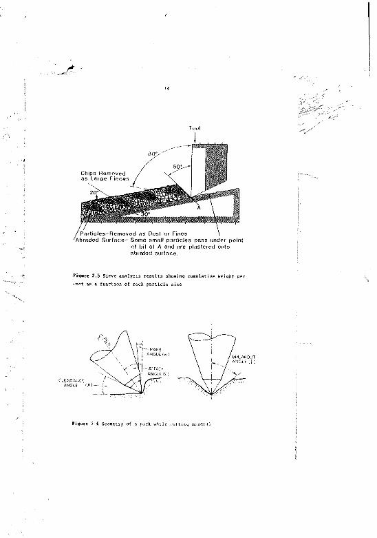
The large chip produced in front of a pick is highly desirable as it indicates an efficient cutting process. However, what is more typical of the cutting process is illustrated by a series of photographs taken of the side view of a tool while cutting rock by Goodrich, 1 9 5 6 ^ Two interesting observations emerge from this, the first being that large chips constitute about one half of tl'e total volume of rock cut as shown in Figure 2.5. The other half is shown to be particles removed as fines or d u s t . The second is that the point of contact between the front or rake face of the pick and the rock surface occurs predominantly very low down the pick face. Goodrich findings comply very closely with those of Tutluoijlu 1983l,°l .
2.2 Pick Condition and Geometry
The condition of the pick influences the generation of forces during cutting. If th° pick is blunt or of an inefficient design, the forces will tend to be higher at all stages of the chip forming process.
The first workable model of the relationships between pick geometry (Figure 2.6) and forces generated during cutting was developed by Evans 1966 *11 *,
The sain relationships illustrated in Figure 2.7 were found to hold for all coals (with different m a g n itudes) and the more important of the fifteen or so attendant principles (Evans and Pomeroy
Tovl
Chips H em ovod as L a rg e P ieces
5 0 1 ^ "
/P a r tic le s -R G m o v e d as Dust o r F ines \'A b ra d e d S u r fa c e - Som e sm all p a r t ic le s pass under po in t
o f b it a t A and are p la s te re d onto abraded su rfa ce .
t Figure 2.5 Sieve analysis results showing cumulative weight per~ T 7 cent as a function of rock particle size
ATTACK I' ANGLEK)
Figure 2.6 Geometry of a pick while cutting mineral
-w 0 10 20 30 60R a k e a n g l e (< *)
10 20 30P i c k w i d t h (m m )
0 s 10 15C l e a r a n c e r n g l e { f I
10 20
IN C n E K tN lA lC U TT IN G
2010D e p t h o f cul {Him) D e p t h o f cut ( m m )
F ig u r e 2 . 7 The basic r e l a t i o n s h i p for c u t t i n g coal w i t h pick
If,
1 «]] :;t udie.> and cut* in] tests sh o w that the total c u t t i n g forceM'-qu;! ed to , ut coal and its comp o n e n t s n a m e l y the c u t t i n g for c e F r , the normal force Frt and the si d e force Fa i n c e a a e li n e a r l y w i t h t h e d e p t h o f c u t . S e e F ig u r e s 2 2 an d 2 .7 A .
? Pic k s w h i c h a p p r o x i m a t e the a n a p e of a s i m p l e c h i s e l a r e m o r e e f f i c i e n t th a n c o m p l e x shapes. The p e n c i 1•point s h a p e is the l e ast e f f i c i e n t A lth o u g h i t a t t r a c t s le a a f o r c e t h a n a c h i s e l i t a l s o
p ro d u c e s le a s c o a l a n d g e n e r a t e s m ore d u s t .
Due to its g e o m e t r y this pi c k is f a i r l y we a k a n d is m o r e v u l n a t e b l e to r a p i d we a r a n d f a i l u r e . T H i s is still a p p l i c a b l e to t h e m o r e m o d e r n pic k s w h i c h h a v e a t u n g s t e n c a r b i d e i n s e r t A p i c k w i t h a c h i s e l (or p o in t a t t a c k a s it is c a l l e d h / v a r i o u s m a n u f a c t u r e r s ) i n s e r t w h ic h u s u a l l y ha v e a c u t t i n g ed g e . ngle of 6 0 " w e r e found to b-- the m o r e e f f i c i e n t for g o u g i n g and c r u s h in g a c t i o n .
3. L a rge pic k s a r e m o r e e f f i c i e n t than small o n e s . T h e f r ont rake a n g le ( a in F i g u r e 2.6 and F i g u r e 2 .7 D ) s h o u ld b e m a d e as l a r g e as
p o s s i b l e b u t p r o b a b l y no g r e a t e r t h a n 2 0 " T h e b a c k c l e a r a n c e a n g le (B in F ig u r e 2 . 6 ) s h o u ld b e n o t l e s s th a n 5 " a n d n o t m ore
than 10" ( s e e a l s o F ig u r e 2 7E).
4 S p e c i f i c e n e r g y r e d u c e s for a l l s h a p e s o f pick a s t h e d e p t h o f
cut is in c r e a s e d S h a l lo w c u t s a r e v e r y i n e f f i c i e n t ( F ig u r e 2.7C).
S. W h e n c u t t i n g d e e p e r the p i c k s in an array can a n d s h o u l d be
p la c e d f u rther a p a r t . For m a x i m u m c u t t i n g e f f i c i e n c y t h e s p a c in g
b e t w e e n p ic k s s h o u l d be a b o u t t h r e e times of th e in t e n d e d d e p t h of c u t (see F ig u r e 2 . 8 R ) . As g r o o v e s a r e deep e n e d , b r e a k o u t a n g l e (6 so F ig u r e 2 . 6 ) i s i n h i b i t e d a n d a d j a c e n t p ic k s a r e p r e v e n t e d from i n t e r a c t i n g . See a l s o S e c t io n 2 3
b T y p ic a l force and y i e l d c u r v e s for pick w id t h are s h o w n in F i g u i e ? ?B. Bo t h a r e found to intercept on t he o r d i n a t e B e i n g a I z. e r o pick width, th e s e a r e th e f o r c e and y i e l d v a lu e s w h o l l y a t ' : i h u t a b l e t o t h e p r o d u ,(ion of s i d e s p l a y n i b r e a k o u t . T h e
i i i c e n e rg y (ends h o w .- v r to r e main u n a f f e c t e d w i t h the pick
17
spacing
d2d3d4d
spacing I d ep th o f cut
Figure 2.8 Hy p o t h e t i c a l r e l a t i o n s h i p b e t w e e n p i c k s p a c i n g and s p e c i f i c e n e r g y
S t a r t o t i n t e r a c t
( s " 2 x d x f a n
P i c k * l o o c k > * *
P i c k # o v e r l a n n
Figure 2.9 Interaction of cutter picks in array
18
7 . Cutting in a corner involves high pick forces and energy. Wherever possible, therefore, an array of picks should provide a cutting sequence that starts with the first pick taking advantage of any available free face and with successive picks progressively extending the free face towards the corner of the excavation. In this way the cutting sequence terminates at the co/ner. It should never start there. Experiments undertaken by Pomeroy and Drown 1960(12) in coal made use of complex geometry. Their findings show that forces in the corner are two to i.hree times greater than thos*? for the free surface and that corresponding specific energies can be four to five times larger in the cornet.
Figure 2.10 illustrates two corner cutting situations using point attack picks. Pomeroy and Brown 1968^12 ̂ also show that the cutting forces generated by a ske w pick tend to rise with the angle of skewing. For example for a in wide chisel pick cutting with a rake angle of 10 degrees and at a depth of 3 mm in a sandstone block, the force involved in cutting a corner is about twice that required on a free surface. Also the amount of material cut per picx in a corner reduced and, as a consequence of this and the higher cutting for-e, the specific energy for cutting in the corner can be as muc h as three times higher than that for the free s u r f a c e .
8. Incremental cutting i.e. cutting gradually with relatively shallow :uts till reaching a given depth of cut is very energy consuming. As the groove deepening case, there is no free coal face and this contributes to high cutting forces. (Figure 2.7F).
o ) CUT W ITH A STRAIGHT HICK b ) CUT W ITH A 4 5 " - TILTED M CK
Figure 2.10 Corner cutting pick situations
9 The application of high pressure (about 220 MPa) water jets to prc slot a block of coal prior to cutting with picks can reduce the pick forces significantly Second method of water jet assisted cutting is by directing a medium pressure (about 35 M P a ) water jrt at the coal face just in front of the pick. The effectiveness of a water jet at the pick face in reducing pick force diminishes rapidly _cn increasing cutting s p e e d . Research work was performed at COMRO by tfojno et a l . * ̂ in 1963 to quantify t h “ reduction in pick forces due to water jet assistance when cutting a typical South African c o a l . Wojno found that reductions in pick forces of up to 60 per cent resulted from directing a 20 MPa water jet at the pick coal interface during laboratory coal cutting experiments.Due to technical limitations, his work was done at a cutting speed of 162 mm/s in comparison to the cutting speed of 2 500 ms/s usee commercially. Figure 2.11 ..hows the reduct in p i k forces when using the jet-at-pick-face (35 MPa) for v«:: ,U8 cutting speeds andfor unassisted coal cutting as found by McVey 1 9 8 7 ^ * .
D E P T H O F C U T (mm)
DEPTH OF CUMmrn
figure 2.11 Pick force against. DOC at var mu;; cutting rprrd -ill, )et; at -pick face assistance
20
2.3 Interaction of Cutter Picks in Array
A mining machine uses an array of picks disposed on soatv form of cuttcr head, drum or jib in which the picks are required to i n t e r a c t . The effect of spacing between picks on their cutting efficiency is important.
If two adjacent picks in the array shown in Figure 2.9 are placed a larye distance apart, s, they cannot interact, and effectively operating as unrelieved cutters, they will aach require the same specific energy. If the picks are now brought closer t o g e t h e r , a position will be reached at which they start to interact, the groove cut by the leading pick providing relief for the following p i c k . It is found that such relief will cause a reduction in the specific energy requirements for the following pick. If the spacing between picks is further reduced, the specific energy will continue to fall but not indefinitely so. Indeed, as the spacing tends to zero, the dept i cut of the following pick tends to zero since it is then cutting . t^xctly in the 'shadow' of the leading p i c k . At th*t position, the specific energy is at a maximum. The effect of j pacing on specific energy t h e refore, as shown in Figure 2.8A, indicates a value of spacing at which the specific energy can be expended to be m i n i m i z e d . In fact a group of curves can be drawn, each showing a minimum specific energy for a different depth of cut and consistent with the general level of specific energy, being lower at the high depth of cut, also, that a wider pick spacing is appropriate when the depth of cut is l a r g e r .
If, as indicated in Figure 2.96, the interaction starts when adjacent grooves just toucn (i.e. s = 2d . tan6), t ke geometrical similarity implicit in the family of. curves in Figure 2.8A can be normalized if the spacing, s, is divided by the depth of c u t , d Now, on the basis of spacing expressed as a multiple of cutting depth, interaction between the grooves will occur at 2 tan6, which is the same for all depths of c u t . Similarly, if geometrical similarity persists, the s/d ratio at which the specific energy is minimized will be the same for all depths of c u t .
21
Figure 2.8B shows how specific energy is expected to vary with s/d ratio, the value of the minimum specific energy reducing at the higher cutting d e p t h s .
2.4 Various Mathematical Models of Rock Cutting
The study of the forces produces when cutting rock has led to the determination of the relationships of pick geometry and pick acting forces. Evans 1 9 6 6 ^ developed the first workable model which encompassed the effects on cutting forces of front rake angle, pick width, tensile strength of the material being cut and the d e pth of cut performed Evans assumed that the type of failure is tensile in character and his model proved to be applicable to other rock ma t e r i a l s .
The mode o f the chip formation was not accepted universally as a tensile fracture and this lead to E r n s t - M e r c h a n t ^ * 1945 model of rock failure which claims that the chip is formed by shear failure. The original model was developed for metal cutting and was modified by Potts and Shuttleworth 1959* *6 * *.0 describe a discontinuous cutting process of shear f a i l u r e .
Nishimatsu 1972**7 * proposed an alternative shear model for rock cutting in which no assumption was made of independence between the shear strength of the rock and compressive stress acting normal to shear p l a n e . This results in h ’ghe- cutting force production for a given depth of cut in comparison to Evans model****. Roxborough 1973*1** made important modifications to E v a n s ' model by adding terms defining the shape of the pick being used, thus extending the practical use of the cutting model in calculating pick forcer, when cutting c o a l .
All models mentioned above agree about the following:
* Cutting forces increases linearly with d e p th of cut (Figure 2.7A) .
22
* Cutting force increases linearly with rock strength.
* Cutting force increases linearly with pick width (Figure 2.7B).
* Cutting force reduces as rake angle increases (Figure 2.70).
CHAPTER 3 DEFINITION OF PICK CUTTING PROFILE FOR CUTSIM APPLICATION
The cutting profile of a single pick is the shape of the groove cut by the pick on a specific mineral. The cutting profile is affected by the type of pick and by the type of mineral cut.
Each pick may have its own cutting p r o f i l e . By specifying a set of conditions for a relevant pick, a wide range of cutting profiles can be obtained. For example, the cutting profile of a straight conical pick (90" to the coal face) will be obtained from the coordinates of points A-0-8 (Figure 3.1). The breakout profile of a 30* skewed pick is shown in Figure 3.2.
CUTSIM enables the user to define any deliberate breakout profile of the pick. For example the breakout profile of a straight pick could be defined as shown in Figure 3.3 or as in Figure 3.4.
The correct breakout profile for any particular mineral should be determined from laboratory tests.
It is possible that the most suitable breakout profile is typicalof the type of pick used in conjunction with the type of mineralcut. Various types of picks may have their individual breakoutprofile fur cutting the same mineral.
The breakout profile shown in Figure 3.1 was found to be the most simple and reliable for simulation purposes, and all cutting analyses detailed in this report were carried out by applying this breakout profile.
3 .1 N u m e r ic a l M o de l
In order to simulate successfully the cutting process, two significant parameters w e re established. These parameters will demonstrate the effect of most cutting situations under actual operating conditions, and effectively replace most of the variables involved
Figure 3.1 Coal cutting profile with a straight pick
4 X2
Figure 3.2 Coal cutting profile with a 30 degree skewed pick
C o a l f ac
Figure 3.3 Cu-tl r u N m y prof i I-'
Coal
C o a 1 f a c e
Figure 3.4 Coal cutting profile
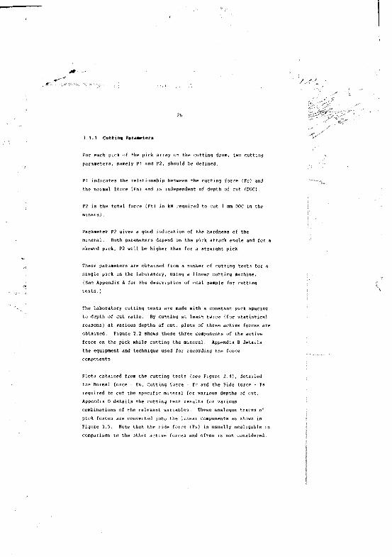
3.1.1 Cutting Parameters
For each pick of the pick array on the cutting drum, two cutting parameters, namely PI and P2, should be defined.
PI indicates the relationship between the cutting force (Fc) and the normal force (in) and is independent of depth of cut (DOC)
P2 is the total force (Ft) in kN required to cut 1 mm DOC in the m i n e r a l .
Parameter P2 gives a good indication of the hardness of the m i n e r a l . Both parameters depend on the pick attack angle and for a skewed pick, P2 will be higher than for a straight pick.
These parameters ate obtained from a number of cutting tests for a single pick in the laboratory, using a linear cutting machine,(See Appendix A for the description of coal sample for cuttingt e s t s .)
The laboratory cutting tests are made with a constant pick spacing to depth of cut ratio. By cutting at least twice (for statistical reasons) at various depths of cut, plots of three active forces are obtained. Figure 2.2 shows these three components of the active force on the pick while cutting the mineral. Appendix B details the equipment and technique used for recording the force co m p o n e n t s .
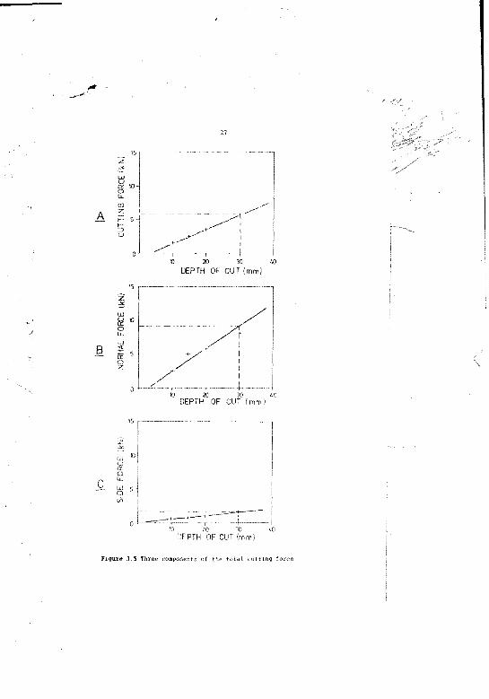
Plots obtained from the cutting tests (see Figure 2.4), detailed the Normal force - Fn, Cutting force - Fc and the Side force - Fs required to cut the specific mineral for various depths of cut. Appendix D details the cutting test results for various combinations of the relevant variables. These analogue traces of pick forces are converted into the linear components as shown in Figure 3.5. Note that the side force (Fs) is usually negligible in comparison to the other active forces and often is not considered.
SIDE
FO
RCE
(kN
) NO
RMAL
FO
RCE
(kN
)
10 20 30 60DEPTH OF CUT (mm)
10
5
0DEPTH OF CUT ( mm)
is
5
10 20 30 60DEPTH OF CUT (mm)
Figure 3.5 Three components of the total cutting force
28
Figure 3.6 is a vector diagram which shows the resultant force Ft: of the three components previously mentioned, fot ,1 selected value Of DOC.
Ft = ( F c Z + FnUFsZ )
The parameter PI is given by
and the parameter P2 is given by
% —
F C U T T I N C
Figure 3.6 Direction of the three components of the total cutting
Section 5 on the a p p l i c a t i o n of thf* computer model shows how th e
parameters PI and P2 piay a major role in the flexible use of CUTSIM for most simulating conditions.
3 . 1 . 2 C u t t in g forces
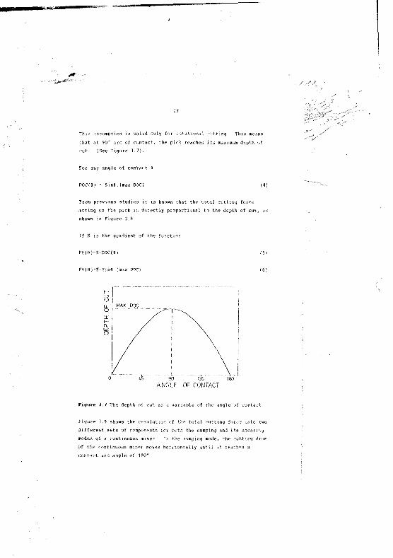
For each p ic k on a cutting d rum , CUTSIM assumes a s m u r oidal p r o f i l e o f th e d e p th o f c u t v e rs u s th e p ic k a n g le o f c o n t a c t .
This assumption la v a l i d only for rotational cutting. This that at 90° arc of contact, the pick reaches its maximum depth of c u t . (See Figure 1.7).
For any angle of contact 9
D O C (# ) = S in # .( m a x DOC) ( 4 )
From previous studies it is known that the total cutting forceacting on the p ic k i c directly proportional to the depth of cut, dsshown in Figure 3.8.
I f K i s t h e g r a d i e n t o f th e f u n c t io n .
F t ( # ) - K D O C (I) ( 5 )
F t ( l ) . K S in # (m ax DOC) ( 6 )
'5'
MAX DQC
100ANGLE OF CONTACT
Figure 3.7 The depth of cut as a variable of the a n g le of contact
Figure 3 .9 shows the resolution of the total cutting force into two different sets of components for both the mumping and the shear) -.y modes of a continuous m i n e r . In the aumping mode, the cutting ilrum of th e continuous m in e r mover, h o r i z o n t a l l y u n t i l .it teaches a c o n t a c t a r c a n g le o f 1 8 0 " .
0 « 20 JO toDEPTH OF CUT (mm)
Figure 3.6 The total cutting force as a linear force
After c o m p le t in g the sumping operation, the cutting drum performs the shearing operation in which it moves vertically to the floor level while cutting with an arc of contact of approximately 90*.
During the shearing mode the following forces act on each p ick:
( i ) F v e r t i c a l r F t ( # ) ' S i n ( * + 6 ) ( 7 )
(ii) F horizontal » F t (6)‘C o s ( 9 ) (8)
( i l l ] Torque = F cutting * r - Ft(0}’Sing*r (9)
r - the cutting radius of the pick tip
Integration of these components on all picks placed on the drum forall possible angles of contact will give the total vertical forces,horizontal forces and torque acting on the drum for one complete
r *
SHEARING MODE
the pickmal (penetrating
Cutting force
- Angle netween Ft andaI - Angle between Ft and
SUMPING MODE
Figure 3.9 Resolution of total cutting force into two different seta of components
12
For a cutting drum with n picks
F total vertical v c r t i c a l l i1=1
(10)
F total horizontal = £ (F horitonzal)i (11)
Torque *otal [ ( T o r q u e ) i i" 1
(12)
The gradient K is determined by linear cutting tes*s See Figure 3.8.
This means that the factor K is identical to the parameter P2
Hence K or P2 indicates the total force in '<N required to cut at a depth of 1 mm in the m i n eral. This parameter i; a good indication of the coal hardness. Note that K is obtained by cutting the mineral with a straight pick.
The angle fl between rt and Fn is also closely related to parameter PI .
From equation (2) P1 = Fc/Fn
Tan 0 = Fc/Fn (See Figure 14) (13)
Hence: pi = Tan fl0 -= Tan't pi (14)
From equation (3) K -
The total torque of all picks indicates the required torque of the cutting machine in order to cut the relevant mineral with the specified number of picks at that specific depth of c u t .
33
The total torque o£ the machine specified by t-he manufacturer should always exceed the maximum total torque calculated by CUTSIM.
The three calculations of horizontal force, vertical force and torque depend on the arc of contact of the drum. The smaller the arc, the fewer the number of picks cutting simultaneously.
The total thrust of the continuous miner divided by the number of picks in the coal face gives the thrust per pick. For an overlaced drum, the thrust per pick is low, due to the large number of picks. Therefore, a reduction in the number of picks laced on the drum will increase the thrust per pick and facilitate a better pick p e n e tration.
*
34
CHAPTER 4 COMPUTER MODEL
In order to simulate the cutting process of a rotating drum with relative ease and enable numerical forces and torque analysis to follow, a computer program was written.
4.1 Advantages of a Simulated Numerical Model
It is extremely difficult to optimize drum design under normal operating conditions because:
* adverse environmental conditions limit the use of sophisticated instrumentation and data acquisition systems
* the nature of the cutting operation is complex so that a large number of picks can be generating both static and dynamic effects on a continuous miner
* production demands limit the availability of the machine for test p u r p o s e s .
An alternative method of optimizing the design of a continuous miner is through the use of a modelling technique. Very good results can be obtained using a numerical model validated against experimental data obtained in the laboratory. A,art from making an analysis possible, a carefully designed numerical model offers the following advantages:
* Reduction of the variables. The engineer can reduce the number of variables dramatically by s sensible definition of a physical situation. It is often found that a large portion of the variables have only a secondary effect on results. By placing restrictions on the model, these secondary parameters can be eliminated. A typical example is sideways or axial movement of the continuous miner. By ensuring that the conditions under which the m ;1el is used are within the restrictions, accuiate results can bi: v U l i m. J .
* Economical analysis. Valid r e m i t s can be obtained by using a computer program and experimental laboratory data, resulting in . significantly lower cost in comparison to the field tests using expensive equipment. It is however very important that results obta.ir~ i from the model be correlated with some form of experimental data from time to time.
* Larger scope The time required to analyse a particular situation is mucn Ir than that required for an experimental program. The net effect of this is that results are obtained faster and a much larger scope of the effects and situations can be s t u died.
* Independent variables. It is often much easier to vary only a single parameter in a numerical model. This will enable the engineer to make a detailed study of the effect of various elements of the model.
4.2 Description of the Model Used
A numerical model is determined by two factors:
* the physical situation to be analysed
‘ the experimental data available for a particular simulation
The objective is to find the best possible model for the situation to be analysed, subject to the limitation of the experimental data.
In order to simulate a cutting situation, the following data is required:
‘ the specific cutting profile of ea c h type of p ic k
‘ the lacing pattern of the picks on the drum
the mineral cutting parameters (PI and P2)
r / "
The fo!iowing assumptions wer? made in order to make the rutting simulation p o s s ib le
* the condi Lion of the pick reaains the iame throughout the cutting a n a ly a is
* the rainera] properties are homogeneous in all directions j
* the cutting drum is always parallel to the coal face and to the JjOOT
* the movement of the cutting drum while1 shearing down is vertical o r l y
36
* the e u * > > nq conditions (se- S e c t i o n 5.3) of the conti n u o u s miner.
4,3 Drum Layout
The cylindrical n a t u r e of the continuous miner drum resulted in the selection of a right handed cylindrical coordinate s y s te m This system was selected for the handling of the drum data as shown in Figure 4.1.
A right handed orthogonal cartesian co-ordinate system was selected to be utied as the global frame of reference for th e system.
This system is used to specify the following:
* the mineral properties la 1 blocks or 1 l-iy^rs within space
* the a c t u a l diam p o s i t io n in relation to tho mineral |
I* the r'-iVV-.ionai velocity of the drum j
|* certain control p a ra m e te rs ( i r . displacement of :.he drum during |the p e r io d in which the a n a ly s is is m ade) f
17
The origin of the cylindrioa1S coordinate system is positioned inthe global frame and it is a;ssumed that the Z axis is parallel tothe global X2 a x i s .
The positic>n of each pick on the cutting drum is specified by itsown cylindrical co-ordinate syst»s positioned on the d r u n . For example the location of pick A ir. Figure 4.1 is determined by the parameters: ra d iu m - r, angle - d (measured from the vertical line OB) and distance Z along the drum,
XXI -TART VALUE
F ig u r e 4 .1 The cylindrical system of * drum and the global frame system
4 4 Mineral Properties
The mineral properties a r e specified in the global co-ordinate system. Blocks of u in e r a l a r e specified (rones on all three a x e s ) , ea'-h wath unique parameters t h a t 'as. influent- - the c u t t in g
mechanism (see Figure 4.2).
a * 3
T
Figure 4.2 Block of mineral in a global co-ordinated system
Figure 4.3 Direclion of cutting in mineral with a large
CUTSIM uses the parameters PI and P2 instead of an internationally agreed standard measure of mineral hardness such as Brinell or Vickers. This results in a more flexible use of CUTSIM and eliminates the use of expensive measuring instruments for defining the mineral hardness.
CUTSIM assumes that the mineral properties are homogeneous, that is, identical in all directions. However, in order to obtain precise and unified characteristics of the mineral, the cutting tests for deriving the parameters PI and P2 should be performed in a standard way, ie. for minerals which comprise large numbers of bands (ie. coal), the cutting test should be made along and on the
40
CHAi R 5 APPLICATION Oi T.l£ COMPUTER MODEL
This section includes d a t a and instructions which are required to run CUTSIM for specific applications. However, in order to demonstrate the flexible use of CUTSIM a n d the way various cutting situations should be simulated, this information is included.
5 . 1 N u m e r ic a l S i m u la t io n o f V a r io u s M in in g C o n d i t io n s
CUTSIM simulates all c u t t i n g conditions irrespective of mineral hardness or pick b l u n tness. The parameters PI and P2 represent the complete cutting configuration and can change with any of the following conditions:
* degree of sharpness (bluntness) of the pick (or p ic k mass l o ss). {See Appendix D)
* mineral type
* pick shape
* water jet assisted c u t t i n g
* skew angle of the pick (See Figure 5.1)
* pick spacing
The effect that the above factors have on the values of parameters PI and P2 is i l l u s t r a t e d in Tables E l to E5 with further explanations provided in Appendix E.
From Appendix E it is shown that for th e most c o a l c u t t in g
conditions, the parameter PI is the ra n g e o f 0,5 to 6,8. The
parameter P2 ra n vary in the range of 0,0? to 1,22 kN/mm for most cutting conditions.
41
Figure 5.1 shows the definitions of the pick skew angle and attack
r Skew angle
/ Direction j / of movement / 'I of cutting head j
£ - Angle o f . attack
F ig u z e S 1 D e f in i t i c m c o f th e p ic k skew a n g le and a n g le o f a t t a c k
5.2 Pick Lacing of the Drum
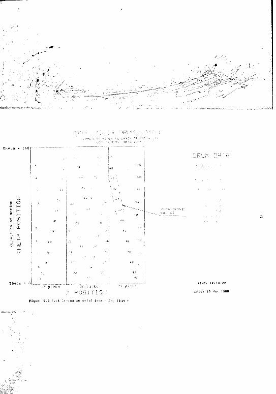
F ig u r e 5.2 shows a typical lacing layout of a continuous minerdrum. The l i n e o f # = 0 indicates thee th e picks adjacent to thisline will cut th e mineral first (picks 1,33 and 40} followed by the adjacent picks (picks 10 and 48) and so on. The picks with maximum 8 angle will cut last, followed by the second revolution of the drum Each number on th e drum layout indicates the location of a s i n g l e p ic k .
For convenience, the relevant d a t a of the pick g e o m e try is best p re p a re d m the form of a table a shown in Table 5.1. Th s data is e n t e r e d i n t o r t lT S IM a n d r e s v i t s i n t h e d ru m la y o u t o f
F ig u r e 5 . 2 .
42
Table 5.1 Tabulation of pick patterns
P ic kGroup
PickDetail Picks
Pick SkewAngle
CuttingRadius
Z m in
2
1 pick A 1 AO 0 559 0 0 429 429p ic k B 2 - 10 10 559 16 216 353 353pick C 2 - 3 0 30 549 72 252 353 353pick D 2 45 45 445 108 288 318 318pick E 2 45 45 521 144 324 318 318
for simplicity this table details only some of the picks used in the drum layout shown in Figure 5.2.
Note that each pick group (minimum two) has a definite geometrical order and can be entered as one pick group in the above table. For example the picks in group No. 47 (Figure 5.2) have the same spacing along the Theta axis and the same spacing in the Z axis-hence they share one entry in Table 5.1.
From the above Table it is seen that pick groups 2, 3, 4 and 5 have different skew angles, and usually the cutting radius of these picks is also d i f ferent.
The values of Theta minimum and 2 minimum of a group of picks should match respectively. T'.iis means that Theta minimum is related to z minimum and vice v e r s a . If they do not, the pick group may have an incorrect geometrical orientation.
The pick code is the name given to a specific group of picks in the pick file and is used for documentation o n l y . All the geometrical data of the pick patterns should be entered on the drum file.(See Appendix K ) .
5.3 Cutting Conditions
Once the cutting profile for each pick with and the parameters PI and P2 have been defined, the f ul] lacing p a t t e r n should be entered
T h e t a = 3 60
in oa
wX
I
T h e t a - 0
Myvtc. rq(,nu%,-L"n ..qpo^'xo-""
DRUM CFTP,
1
I "/'l
, JGi
36 p i c k s
P O S I T I O N2 1 p i c k s
p ic k group no. 47
2 p i c k s
F ig u n 5 . 2 P i r k lacing on solid drum • Joy 14CM 9
DAI Ci 2 0 M a > I
on the data disk of CUTSIM. An analysis of the breakout profile resulting from the lacing pattern of the cutting head can then be obtained (see Figure 5..1). The analysis requires a set of input data to define the cutting conditions. (See Table 5.2).
Only relevant data should be entered. Normally, many entries will bt left as zero, because provision has been made in the program for the future inclusion of various types of machinery.
Drum rotation [rpm] 60Time increment [s] 10,000Drum 2 increment [mm] 10Drum X1 start value [mm] -250Drum X2 start value [mm] 0D rum X3 start value [mm] 0
Maximum analysis time [s] 10Maximum analysis theta [0] 0Maximum analysis XI [mm] 0Maximum analysis X2 [mm] 0I range minimum [mm] -200Z range maximum [mm] 1500
b velocity [m/s] - The forward drum velocity in m/s.(See Figure 4.1). This is equivalent to the forward velocity of the continuous miner or the linear velocity of the longwal1 shearer.
X3 drum velocity [m/s] - The vertical drum velocity in m / s .(See Figure 4.1). Used only when simulating vertical cutting of continuous miner, shear mode or complex mining in vertical and horizontal axes simultaneously.
Drum rotation - The i Figure 4 1).
olutio per minute (see
Fig
ure
5.3 The
brea
kou
t p
rofile
o
bta
ined
by
using Z
Xi VELOCITY- .03 X3 VELOCITY- 0 ROTATION- 60 r' r ROTATIONS - 2
COAL MINER CUTTING PROFILEO r M IN L 5 RF.SLARCH COAL LMBOROTCRY
X2 INCREMENT- 1
? MINIMUM- -SB
2 MAXlrtM- 400
XI MINIMUM- 0 mm
Xi MAXIMUM- 2B2 mm
WINDOW MIN- -53 MAX- 402
Drum Z mcrerenL 1Time increment 10X. Start value -50Max. analysis lime 10
,U
zo
inoCL
X
Z POSITION
ii
nc-enent interval jn CUTSIM is used as an.-Iternatv .r to theta (the angle of contact - seeFigure -?.r ing the drua rotational velocity andthe dru# rtvy. the time increment indicates the locatio:of each pick at ai.y m o m e n t . In the data entry for the cutting conditions, the time increment and the maximum analysis time can be di f f e r e n t . However, for the regular use of CUTSIM, enter these two parameters as 10 seconds.
Drum Z increment - This indicates the axial resolution to be used in mm.
The minimum required value is 1 mm. For regular use of CUTSIM, enter Drum Z increment as 10 mm. The greater th» Z increment, the less accurate will be the breakout profile but the program will run considerably f a ster.Figures 5.3 - 5.5 show the effect of various drum Z increments. The breakout profile in Figure 5.3 is calculated for 1 mm resolution. Hence the profile is unified and very a c c u r a t e . Figures 5.4 and 5.5 show the same breakout profile calculated for 10 mm and 30 mm axial resolution respectively, hence the obtained profile is considerably less accurate.
Drum XI start value (mm] - This indicates the initial position of the drum in relation to the coal face. From Figure 4.1 it can be seen that this entry will always be negative in s i j n .
Drum X2 start value [mm] - not applicable, reserved for future use.
Drum X3 start value [mm] - not applicable, reserved for future use.
Maximum analysis time [sec] not applicable, normally enter 10, as was explained previously when discussing the timeincrements. j
I
Figuxe j.4
The breakout
profile obtained
by using
2 increment
= 10
C O A L M I N E R C U T T I N G P R O F I L ECHAMBER OF MINES RESEARCH ORGANIZATION
COAL MINING LABORATORY
DRUM NRi 003!
XI VELOCITY- .03
X2 VELOCITY- 0
ROTATION- 60
ROTATIONS - 2
XZ INCREMENT- 10
Z MINIMUM- -50
Z MAXIMUM- 400
XJ MINIMUM- 0 mm
XI MAXIMUM- 262 mm
WINDOW hIN- -50 MAX- 4B0
Time increment X. Start valueMax. analysis time
Drum Z increment
10 .
-5010
23*-
C u tting order o f pick
to
z POSITION
Figure 5.5
The breako-t
profile obtained
by using
Z
COAL M I N E R C U T T I N G P R O F I L ECHAMBER OF MINES RESEARCH ORGANIZATION
COAL MININ: LABORATORY
jjRUM NR: 0831
XI VELOCITY- .03
X3 VELOCITY- 0
ROTATION- 60
ROTATIONS - 2
X2 INCREMENT- 30
Z MINIMUM- -50
Z MAXIMUM- 400
XI MINIMUM- 0 mm
X! MAXIMUM- 262 mm
WINDOW MIN- -50 Drum z increment 30
Time i n c r e m e n t 10.X. start value -50 Max. analysis time 10
ZO
If)oCL
X
Z POSITION
Maximum analysis theta [#] - not applicable, reserved for future
Maximum analysis. XI (mm] not applicable, reserved for future
Maximum analysis X2 [mmj - not applicable, reserved for future
Z range ain/max [am] - The range to be analysed in the axialdirection of the d r u m . Normally the minimum Z range will be less than the actual minimum Z in order to include the drumedge. It is recommended that the whole range of the drum isanalysed and later, the user can zoom to the relevant part of the drum.
5.4 Cutting Profile of the Drum
Once all cutting conditions have been specified, CUTSIM is ready to analyse the breakout profile of the whole drum. See Appendix K for an activity flowchart. Table 5.3 details the additional required data input for the display of the breakout profile.
Table 5.3 The required data for the breakout profile of a drum
Cutting P.ofile Analysis
Number of rotation 2X1 drum velocity [m/s] 0 , 0 3Plotter addressWindow minimum [mm] 5 0Windov Ma x i m u m [mm] 500R ava dynamic data [Y/N]ni'i'.k plot [ Y /N ] N’lot group number (Y/N] YPlot wic*o.>t iiumbers (Y/Nj N
Nt te that in case of contradictory data (for example 'Plot group number Y' ami 'Plot without numbers - Y 1), a system error will
Number of rotations: The user of CUTSIM can enter any requirednumber of drum rotations. Normally, two are sufficient to ^ ^cover all a s p ects. The greater the number of drum rotations, the more time needed for processing and plotting.
XI drum velocity [m/s): This is the same XI drum velocity which was required in the cutting conditions.
Plotter a d d r e s s : Enter 3 for plotting on the computer screen iC R T }. Enter 705 for the Hewlett Packard plotter. Alternatively press dump graphics for a hard copy from the printer after plotting on the CRT.
Window mir/max.: CUTSIM enables the user to determine a breakout profile for any spectra zone of the drum. This is done hv specifying the required zone by entering "Window minimum" and "Window maximum". Note that without exception "Window minimum" > z minimum and "Window maximum" < z maximum. A contradictory range of Window or Z will result in a system error. Figure 5.6 shows an example of zone selection for the breakout profile shown in Figure 5.5.
Save dynamic data [Y/N): Enter "Y" i f you have made any changes in the cutting conditions since the last processing data stage. (See Appendix K for an activity flowchart). For the safe use of CUTSIM it is good practice to re-save the dynamic data file by specifying "Y" before proceeding further.
Quick plot [Y/N): The response "Y", will result in the breakout profile detailed in Figure 5.7. All the descriptive data will be missing. Use this utility for a quick draft only. For the final and full plot, enter "N".
XI
POSI
TION
C O A L M I N E R C U T T I N G P R O F I L E
DRUM NR: 0031
XI VELOCITY- .03
X3 VELOCITY- 0
ROTATION- S3
X2 INCREMENT- 10
7 MINIMUM- -50
Z MAXIMUM- 408
XI MINIMUM- 8 mm
XI MAXIMUM- 175 mm
WINDOW MIN- 50
MAX- 350
DATL- G O.l I
pick group number
Z P O S I T I O N
F i g u i e 5.7 The b r e a k o u t profile o b tained by using 'quick plot:
Plot group number [Y/N]: The group number is as entered into thedrum file (See Table 6.1). Enter 'Y' if you want to sec the group number of the pick as it is shown in Figure c-. 6. Thiswill enable the user of CUTSIM to identify any certain pickon the breakout profile.
Plot without numbers [ Y /N]: Enter Y" if you want the breakoutprofile plotted without any numbers (pick group numbers orthe order of cutting). To be used normally for the breakoutprofile of the whole drum, where there is not enough sp.’ce for the numbers (see Figure 5.8). Enter 'N', ,<nd the output will be as shown in Figure 5.4. These numbers show the order in wh eh the picks enter tne coal during one revolution. This feature could be used for designing a cutting drum for tracing the cutting order.
5.5 Analysis of Continuous Miner Forces and Torque
CUTSIM resolves the total force acting on each pick for each degreeof contact (or for every five degrees of contact, used for quick calculation) jnto two mean components, namely vertical force and horizontal force. (See Figure 3.9). The program then integrates all the vertical components into a total vertical force. The same procedure takes place with the horizontal components. The calculation of the torque is performed as indicated previously by applying the equations 9 and 12.
Normally for general use of CUTSIM, the force analysis will be done for two typical arcs of contact, namely 90* for shearing mode and 180* for sumping mode as shown in Figure 3.9. However CUTSIM r. also perform the torce analysis for any arc of contact Note tht. in certain circumstances, due to the nature of rotating crmponent it is possible to obtain lower forces while cutting with a larger arc of c o n tact.
CUTSIM will determine the following factors which can be used fc
COAL MINER C U T T I N G PROFILECHnnatR o r mines reberrcm orgrnizrtion
COflU MINZ^ LABORATORY
D9UM W 2 1 Xi /LLOCTTY- .83 X3 VLuOCITY- 0
ROTATIONS - 2
<2 INCSCM&NT- 10
Z MINIMUM- 250
Z MAXIMUM- 3RS0
X i MINIMUM- 0 trm
XI MAXIMUM" 1983 nm
WINDOW MIN- 250
DATE: 15 Dec 1987
TIME: 15:42:58
Is
f
zoI—
oCLX
"5373"
Z P O S I T I O N
* ot v M l i c a l (orcea
* magnitude jf horizontal forces
* amplitude and frequency ot vertical forces
1 amplitude and frequency of horizontal forces
* magnitude of the required torque
1 amplitude and frequency of the required torque
* number of picks on the cutting drum
‘ average product size
‘ presence of "’ie or non productive picks
* analysis of the performance of the gauge picks
‘ generation of mintral cores b e tw e e n drum segments {continuous min-ir o n l y ) .
* calculation of average specific energy for one diua rotation
* the possibility that the gauge cutters will release the broken mi n e r a l .
Some examples of how the above criteria can be applied, will be provided in Chapter 6
5.6 Corner Cutting Drum Design
In every excavation there is at least one corner which defines the boundary of the cut volume and in which the cutting process is likely to be impeded because of the constraint imposed by the
'
56
corner, A corner cutting situation may develop where the sequence of picks becomes discontinuous e.g. at the hub spaces between the drum sections where a coal core tends to be generated.
On most of the Joy cutting heads there are 10 gauge picks at each edge of the drum. For an average lacing of 65 picks, these gauge cutters form about 31 per cent of the total picks used. Therefore it is very important to understand the behaviour of gauge cutters and to be in a position to improve or optimize the design of corner-cutting a r r a y s .
Figure 2.10 illustrates two corner cutting situations using point attack p i c k s . The straight pick disposition is not common in practice because of the clearance difficulties. However, some longwall shearer drums and coal ploughs still use corner cutting picks approximating to it. Skewing the pick to provide clearance for itself and its holder is the more usual practice. Skewed picks are also used on the continuous miner drum in order to cover the hub spaces and prevent generation of a coal core.
The increased duty of the gauge cutters is manifested by the high incident of damage to these picks and pick b o x e s . This problem is generally overcome by using two or three sequences of picks to cut the corner of the excavation instead of one sequence as is used for the line cutters. In this way, corner cutting picks operate at only one half or one third of the depth of cut to which line cutters penetrate.
A close analysis of the breakout profile of the Joy 14CM 9 continuous miner (Figure 5.9) shows that the corner cutters at each edge of the drum tend to deepen a groove in advance of the line c u t t e r s Enlargement of the left hand section of the drum for30 mm per cycle forward drum velocity (Figures 5.2 and 5.10), shows that the gauge cutters have generated a groove which is about 22 mm in advance of the 1 m e cutters. In oi dr; *• ' oi t i :m per formance of t h i s drum and overcome the a d v e rs e cut' i ng e i i ••v • . :
both corners, a new lacing geometry was suggested. If the curved broken line (Figure 5.10) is the new coal face, this will result in
Figure 5.9
The breakout
profile cf
Joy 14CM
9
C O A L M IN E R C U T T I N G P R O F I L E
O q U M \ q - QC17 <1 /EuOCITY. .03 Y2 /CLOCITf- 0 qcrnriON- me qOTMTIONS - 2
CORL MINING LABORATORY
INURF.MLN:- 18 Z MINIMCM ")R0 Z :in50
<1 MINIMI'M'./ r-m <f MAVrMUM" 299^ nr
Mix-- .
DATE • i '? Ma
Zo c o rner cutting with gauge c u t ters
h~MmoCLX
Z P O S I T I O N
COAL MINER CUTTING PROFILECHRMaCR o r MINES RESEARCH ORGANIZATION
COAL MINING LABORATORY
DRUM BE I .'X] /E_OLiTY- .03
^3 ^LLOCiTY- 0 RornrioN- sa
10Z MINIMUM. TREz "ixiMjM-
XI MINIMUM̂ P .-rn,
x:N..
o
h-
inoELX
corn e r c u t t i n g with gauge cutters
Z P O S I T I O N
I
COAL MINER CUTTING PROFILECHAMBER OF MINES RESEARCH ORGANIZATION
COAL MINING LABORATORY
ir
I Is
ARUM NP- 0'03
X: VELOCITY- .33
X3 VELOCITY- 0
ROTATION- GP
ROTATIONS - 1
Kj INCREMENT- 10 Z MINI"UM- 308
Z MflXirjM- 1303
XI MINIMUM- 0 =un
XI M A X I M A - 48B
h iN rO y l M IN -
nTL- -u, in-..
440
forward displacement
Zo the proposed newg r oove deepening
gauge cutters
inoCLX
Z POSITION
#**' -
- -
59
overcoming the problem of groove deepening and no coal will be impeded due to the corner geometry. CUTSIM can simulate easily a new pick lacing by reducing the cutting radius of each pick yroup invol v e d . By using the scaling technique, the cutting profile of picks 1, 2, 3, 4 end 5 should be brought back to the new curved line or below as shown for pick group 2. This will result in a new cutting radius for each corner pick and not a common radius for each group pick as before.
Table 5.4 s M w s the old and the new cutting radii for the corner cu t t e r s .
Table 5.4 Pick radii of the corner cutters
PickGroup
Original Pick Radius (mm)
New Calculated Radii (mm)
Front Pick Back Pick
1 559 532 5052 55 9 492 4653 549 477 450
445 352 3255 521 422 396
The new cutting profile of the let* hand section of the drum is shown in Figure 5.11. Note the new coal face o b t ained.Figure 5.12 shows the new coal face of the whole drum obtained by using the new pick radii at both e d g e s . The benefits of this new lacing are demonstrated also by the forces and torque analysis in Table 5.5. Table 5.5 shows that the torque required and the acting vertical and horizontal forces results in an average reduction of 5 per cent for the proposed lacing compared with the original lacing. See Appendix C for more details about the cutting simulations and other related data concerning the corner cutting. Although the proposed lacing shows an improved means of cutting in a corner, one should beat in mind that this approach has not been tried yet m the f i e l d .
50
T a b le 5 . 5 C o m p a ris o n o f f o r c e s a n d t o r q u e f o r o r i g i n a l and
p ro p o s e d la c in g
Origina Lacing Proposed Lacing
Sutnping Shearing Sumping Shearing
Average torque (kN m) 96 48 91 46
Average vertical force (kN) 136 112 129 106
Average horizontal force (kN) -137 -26 -130 -25
The redesign of drum corners could be further improved, probably by reducing the number of picks and using a different lacing.However, machine designers think that the existing corner lacing is the appropriate one f o r enabling the continuous miner to turn and start a new road. For this specific application, further studies should be done in order to optimize the drum corner lacing.
5.7 Simulation of a cutting drum with ripperveyor
A ripperveyor is a chain laced with picks which usually is located between two sections of solid drum (see Figure 1) and rotates at a different tangential speed to that of a solid drum. Due to the geometrical construction, a cutting simulation of a configuration made of two solid drum sections and a ripperveyor is a complex matter. This is mainly due to ripperveyor having a different cycle time of the pick lacing pattern than che drum sections ie. line AOB (Figure 5.13) will approximately be transformed to line AOCD after one drum revolution. However if the pick lacing pattern of the ripperveyor is fairly simple and made of many identical pick groups, this will make a cutting simulation possible. Such a simulation can show mainly two important aspects, namely
• the cutting performance of the ripperveyor
* the possibility of generating a coal core between the ripperveyor and the solid drum.
Figure 5.11
The new
curved coal
face
r
C O A L M I N E R C U T T I N G P R O F I L ECHRMBEH OF MINES RESEARCH ORGRHIZRTION
COAL MINING LABORATORYDRUM NR: ai0d
XI VELOCITY- .33
X3 VELOCITY- 3
ROTATION- 50
ROTATIONS - 3
X2 INCREMENT- 10
Z MINIMUM- 333
Z MAXIMUM- 1303
XI MINIMUM- 3 M
XI MAXIMUM- 438 mm
INPCW M:\P
Zothe pr o p o s e d new gauge cutters lineMinoCL
X
Z P O S I T I O N
Figure 5.12
The new
breakout profile
of the
whole drua
COAL MINER CUTTING PROFILECHAMBER OF MINES RESEARCH ORGANIZATION
COAL MINING LABORATORY
DRUM NP Biai
X. VELOCITY- .93
X3 VELOCITY- A
ROTATION- GB
ROTATIONS - 2
<1 MINIM,
XI MAXIMU
:ry 1983
zo the p roposed new
g a u g e cutters line
M(/)oCLX
Z P O S I T I O N
figure 5.13
Th* pick
lading of
lii-perveyoz: Joy 121*
9
O r MINES RESEARCH ORCRNIZPITION COriL MINING LnBORFTORY
inoCL
CEI—UJ
13 14:a M
is it i* :e
A _ 0
\y
i ? :
17 IB- 8
Z POSITION
D R U M n p r n
i - or -re.
: R — ' \ , ''37!
TIMEl 01134:24
DATE; 3 Jun 1989
Figure 5.13 shows the lacing patterns of the two solid drum sections and the ripperveyor between them, as used on the drum of the Joy 12KM 9 continuous miner.
This figure shows clearly that the pick density m the ripperveyor section is much higher than in the other two drum sections.
Figure 5.14 shows the cutting profile of the whole drum. The overlaced ripperveyor is clearly seen i.i comparison to the othei two drum sections. For the simplicity of this cutting simulation, it was assumed that all drum section- are rotating with the same tangential speed. This assumption may be wrong but due to the fact that the cutting speed is independent of the generated cutting forces, it is acceptable for such an application.
Figure 5.15 shows the breakout profile of one section of the whole d rum for XI velocity of 30 am per revolution. The inefficient cutting of the ripperveyor section is very clear. Both Figures 5.14 and 5.15 show a gap cf 130 mm between the extreme gauge cutter of the ripperveyor (pick group 11) and the extreme gauge cutter of the left hand drum section (pick group 28). This will result in generating a coal core which will have an adverse effect on the performance of the continuous miner. The overlaced ripperve/or section is the main reason for the large amount of dujt generated and small product size. For these reasons the industry is moving away from the ripperveyor type continuous miner to the solid drum continuous m i n e r .
' - ' '
CO A L M I N E R C U T T I N G P R O F I L E
TIMETi 0 3 :1 4 i 30
1511 2 3 3 3
Z P O S I T I O N
pabiptua dm
%% % aintTj
C O A L M I N E R C U T T I N G P R O F I L ECHfMmLQ or MiNis SE.5..mRCH o^GRsiznriox
COAL 1NING LHBORArORY
2 1NCRLMLN
Z MINIMUM. 308
(: ./an
MAXIMUM- 52"- :
HINUOW M IS - HOB
MCM-. ;;gr:
DRTEi 3 Jun 1888 T IM E i 0 9 : 2 9 : 1 2
130 m m
T f w A k : ------m r
Z P O S I T I O N
I
CHAPTER 6 VALIDATION OF FINDINGS eg
In ord e r to v alidate the C U T 5 I M findinys , the (ollowing three 'd i f f e r e n t m e a n s were used. i
* c o m p a r is o n of simple dr u m m a nu a l c a l c u l a t i o n s with C U T5IM output i
* c o m p a r is o n of. C U 7 S I M o u tput w i t h the force a n alysis of the Lee \
N o r s e e x p e r i m e n t a l contin u o u s min e r u n d e r g r o u n d trials \
* c o m p a r i s o n of C D T S I M o u tput w i t h a c tual tests c onducted Iu n d e r g r o u n d o n a produ c t i o n c o n t i n u o u s m in e r j
6 . 1 Validation against Manually Calculated Forces
A s i m p l e d r u m of only three picks was u s e d for the m anual
c a l c u l a t i o n of forces and torque. T h e manual c a lc u la t io n s were then com p a r e d w i t h the C U T S I M o u t p u t .
Figu r e 6.1 shows the pick 1 locat i o r d e r and n o t a t i o n of the picks
on the r o tating drum. Note the
Figure 6.1 The lacing pattern of the test drum
69
At 0° pick 1 is ready to start cutting. Pick 2 and pick 3 are behind pick 1 at ancles of 40 and 80* respectively.
The pick spacing is 76 mm (Joy standard lacing). F igure 6.2 shows three picks on the test drum. Table 6.1 shows the entered data on the drum file for this particular simulation.
Table 6.1 Pick la data of the test drum
PickCroup
PickDetail
No .£ Picks
PickCode
SkewAngle
CuttingRadius(mm)
2
(mm)
z
(mm)
3 A0 0 457 0 80 100 252
F t (8) = K SinB {max DOC) ..... from eqi,„i :,m (6)The max DOC is obtained foi 8 = 90.
The following assumptions are aade for the simplicity of calculation:The max DOC in coal is 30 mm per drum revolution.K=1 (the slope of the cutting force against DOC is 45*). Fc=Fn.This results in P;=Fc/Fn - 1Hence for max DOC Ft(90) = 1-Sin (90)- 30=30 kNP2 = Ft(max)/max DOC ..... from equation (3)Hence: P2 = 30/30 = 1 kN/mra
Using CUTSIM with these values for PI and P2 gives the following
* the coal cutting profile with pick group number as shown in Figure 5.3
* the CUTSIM continuous miner forces and torque analysis for the shearing mode as shown in Figure 6.3.
Figure 6.2
The lacing
pattern of
the test
drum
ZO
<S)
2
: 04l _ - R U M L . A Y O U
CHAMBER OF MINES RESEARCH ORGANIZATION COAL MINING LABORATORY
DRUM DATA
TING :1 . 1
MAXIMUM - DRUM wEN ■
FAR 1 • PAR c • PAR 3 - PAR PAR 3 -
LUX
Figure 6.3
The cutting
forccs and
torque of
COAL Miw&R l-CRCESCHAMBER OF MINES RESEARCH ORGANIZATION
COAL MINING LABORATORY
DRUM NRi 8001
XI VELOCITY- .03
ROTATION- 60
CONTACT ARC- 90
DATL- L 0 M * r 19(1/
TORCUC
VERTICAL
HORIZONTAL
TH
71
The manual calculations which follow are detailed in order to demonstrate typical forces &nd torque calculations for two different pick positions. The output of these manual calculations is then compared with the CUTSIM analysis for validation.
Figure 6,4 shows the position of pick 1 at 81-10* and the forces
The pick radius is assumed to be r-457 mm which similar to that of a Joy 14CM 9 cutting drum.
At 81=10* only pick No 1 is cutting.
Figure 6.4 Pick position for 01 = 10"
Depth of cut for pick No. 1 (D0C1) i s :
D 0C1=Sin(81)*{max DOC) = S i n { 10)*30=5,2 mm from equation (4).
The total force acting on pick No. 1 (Ftl) is:
72
Ft 1-K*D0C1“ 1 *5,2 = 5,2 kN from equation (5)
3 1 -Tan' 1 f1 ,1= T a n "5{ 1 ) = 4 5 ® .... from equation (11).
T2=Ft2 * Sin(82)«r = 7,76 * Sin i 4 5)*u,457 = 2,51 kN*a
Integration of all force components and torque g i v e s .
Ifv = F v H F v 2 » 24,2+6,72 = 30,92 kN
CFh - Fh1+FK2 = -4,27+3,88 = 0,39 kN
[T = T1+T2 « 7,94+2,51 10,45 kN'm
These manual calculations for two selected pick positions are typical of computer calculations for any pick at any location.
A ddt;ivnal manually calculated forces for 26 different points for each of the vertical forces, horizontal forces and torque are detailed in Appendix F.
ft- --
Figure 6.6 shows a plot of the manual calculations, namely the vertical force, the horizontal force and the torque for the shearing m o d e . Both plots of the manual calculations (Figure 6.6) and the CUTSIM output (Figure 6.3) are identical.
This excellent correlation of manual calculations and CUTSIM output is part of the validation used to prove the reliability of CUTSIM pr o g r a m .
6.2 Comparison of CUTSIM with the Lee Norse Findings
The CUTSIM output has been compared with the findings of the Lee Norse continuous miner detailed in Research report 23/79(4* by King et a l .
The Lee Norse miner used the following parameters:
The comparison with CUTSIM was based on four different pick lacing patterns used on the Lee Norse. These four Lee Norse pick lacings (Figure 6.7) were simulated by CUTSIM using the same parameters as far as possible. However, where relevant data was missing, reasonable assumptions were made in order to provide the missing
Simulations were performed for four lacing patterns, using depths of cut of 10,20,30 and 40 mm with pick spacings of 50,100,150 and 200 mm respectively. Details are provided in hppendix H.
It was assumed that all skewed picks on the Lee Norse drums were at 30" (positive or negative angle). Parameters PI and P2 for the Lee Norse Simulation were obtained by cutting a sample of coal from Majuba colliery with a straight pick. By keeping the pick spacing to depth if cut ratio at 3:1, the parameters PI and P2 were
FOR
CE
6030
VERTICAL FORCE (kW
TORQUE ikH-m!
L0 <00 BO I ' SQ0 6o -GO 160 THETA POSITION
HORIZONTAL FORCE !kN)
- 60 J—
F i g u r e 6 . 6 Manual c.i i cu lat i on of forces .-md torque
P E R M A N E N T GAUGE —
CUTTERS
QUANTITY
STRUTS
PERMANENT — GAUGE
CUTTERS
2 GAUGE CUTTERS 2 GAUGE CUTTERSEITHER SIDE EITHER SIDE
TOTALS
GAUGE P IC KS 8 2 2 2 2 8 24
1 ‘A' P IC K 6 K 23 U 51
J 75
\ /
^ GAUGE P IC KS 8 2 2 2 2 8 24
A' P IC KS 7 12 7 26
" X50
> V f
GAUGE P IC KS 8 2 2 2 2 6 24
A P IC K S 5 8 5
u)T WlP
GAUCE PICKS
A PICKS
P igur-! 6 ,7 The lacing p n tfe rn s for varjLeft N o ise drum
T6
30
3P*eings used *. n fhe
7 7
For 0 e skewed pick (straight pick) PI r 0,71 and P2-0,')4 kN/mm.For 30" skewed pick P1-S,78 and P2=0,65 kN/mm. (See Table E.5).
Table 6.2 details the normal forces and torques o' the Lee Norse as calculated using CtPTSIM. Appendix I details the CUTS IM simulations of the Lee Norse t e s t s . The Table also indicates the derived cutting forces and torques from these simulations.
For this comparison, the shearing and sumping modes described in the Lee Norse report are equivalent to arc of contacts of 90" and 180* in the CUTSIM program respect: '-.ly. figures 6.10 and 6.11 show graphically the comparison between the Lee Norse torque and the CUTSIM torque for 180* and 90" arc of contact respectively. In Figure 6.9 the average normal force and the maximum normal force of CUTSIM are respectively below and above the nominal boom force of Lee Norse. Figure 6.9 reflects the general tendency seen in Figures C.10 and 6.11 considering the circumstance of this comparison, it is an acceptable correlation. Figure 6.8 is unusual as it shows that the Lee Norse boom force is much higher than the maximum normal force of CUTSIM. For 200 mm pick spacing the difference between CUTSIM maximum normal force and Lee Norse boom force is 117 per cent for the sumping operation.
The differences between the CUTSIM calculated forces and torques and the Lee Norse measured boom forces and torques could be due to the following:
* CUTSIM program does not take into consideration any resistance of the broken coal. It was found, in an actual coal cutting t e s t ,
that the broken coal in c r e a s e d the measured forces significantly.
‘ According to th e Lee Norse r e p o r t ^ * (Page 37), the depth of cut was not a controlled v a r i a b l e in the tests conducted. 'T h e
machine advance could be roughly predicted according to the am ount
of thrust or shear pressure to be applied. Consequently th e
procedure was to a im for a 'deep', s h a l lo w or 'medium' depth andto set the hydraulic pressures accordingly'.
Table 6.2 Lee Horse: COTSIN generated normal forces and torque
CUTSIM - Normal forces and torque output
Shearing - Arc of Contact 90*
SumpingContact
Arc180
of
Depth of cut (mm) 10 20 30 40 10 20 30 40
Pick spacing (mm) 50 100 150 200 50 100 150 200
Crura number 0030 0027 0028 0029 0030 0027 0028 0029
Average normal force (kN)
32 43 46 49 4r 51 54
M a x . normal force (kN) 39 58 65 75 47 65 63 75
Average torque (kN,is) 13 22 23 25 27 44 45 50
M a x . torque (kN*m) 18 37 36 39 29 58 53 58
Table 6.3 details the boom forces and torques measured during the Lee Norse t e s t s .
Table 6.3 Lee Norse: measured boom forces and drum torques
Lee Norse - Boon forces m d torque readings
Shearing Arc of contact 90*
Sumping - Arc of contact 180“
Depth of cut
Pick spacing
Nominal boomfon'e {kN)
Nominal torque (kN*m)
10 20 30 40
50 100 150 fJO
17,8 S0.1 62,5 85,1
12 19,S 29,3 45.5
10 20 30 40
50 100 150 200
58,2 91,3 112,5 163,1
14,8 24,6 31.9 50,5
Figures 6.8 and 6.0 show graphically the comparison between i ;.e Lee Norse boom forces and the CUTSIH normal forces, for 180” and 90" arc of contact respectively.
A R C OF C ONTACT ISO0
50 100 150 200PICKS SPACING ( m m I
F ig u r e 6 . 8 C o m p a ris o n of Lee Norse Boom f o r c e s and CUTSIM normal forces - sumpiruj mode
AR C OF C O N TAC T 9 0 ‘
PICKS SPACING { m m )
Figure 6.9 Comparison of Lee Norse Boom forces and CUTSIM noim.il
!
I
A R C OF C O N T A C T 90 ‘
P IC K S S P A C IN G im m )
F ig u r e 6 . 1 0 Comparison of Lee Norse and CUTSIM torque - shear mode
ARC OF C O N TA C T 180*
E 60-
P IC K S SPACING imm
F ig u r e 6 . 1 1 Comparison of Lee Norse and CUTSIM torque - s u a p m g
• The forces in the Lee Norse report are given in two components; namely, force along the boom and the cutting force which is v e r t i c a l to the boom force. Assuming a boom angle of 20* from the floor, which is an approximate average working angle of the boos this will result in a 6 per cent reduction in the total force if it is resolved into horizontal and vertical components as in the CUTSIM program. (See Figure 6 . 1 2 ) .
F ig u r e 6 . 1 2 Boom force given in Lee Norse report compared w it h Fv and Fh in COTSIH
* In the Lee Norsr tests, the centre drum was laced with 12 picks at 100 mo spacing {See Figure 6.7), but CUTSIM simulates the use of 11 picks on the centre drum as specified in the Lee Norse manual by the manufacturer.
* The CUTSIM program assumes sharp picks throughout the cutting process which contributes to minimal acting forces (see Section 4.2). During the Lee Norse tests, not all of the picks were new and sharp during cutting trials.
* The exact geometry of the pick lacing on the Lee Norse d r u o ^ is not fully available and various techniques of interpolation and scaling have to be applied in order to get approximate figures.
‘ CUTSIM uses two different cutting parameters PI and P2 as already mentioned. These parameters are obtained by cutting tests on a sample of coal from the relevant s e a m ,performed on the linear cutting machine at the Coal Mining Laboratory (CML) of the Chamber of Mines. Due to the nature of the coal, these parameters can vary for each seam of coal, the coal cutting conditions and the quality
82
of the cuttniij tool . It ts known that the coal cut by the Lee Norse and the coal cut at CML for the parameter extractions had different characteristics.
* The forces and torques presented in the Lee Norse r e p o r t ^ were determined from hydraulic pressure readings which was dependent on the setting of the machinery and regular calibrations being done. This could have led to additional inaccuracies.
* In the Lee Norse tests, the ratio of pick spacing to depth of cut was 5:1. This ratio is too high for good cutting interaction and contributes to very high cutting forces. The parameters PI and P2 used in the cutting simulation of CUTSIM are based on laboratory cutting tests using 3:1 ratio. This ratio is ideal for cutting interaction and ensures that cutting forces are at a minimum.
* Due to the lack of exact data on Lee Norse pick lacings, it was assumed that all skewed picks on the Lee Norse drum were at angles of 30 or '30*. The CUTSIM simulation was based r , this assumption which may have been incorrect.
6.3 Experimental Underground Tests
This section demonstrates how CUTSIM can be used in order to improve the cutting performance of a given lacing.
Cutting tests, using a Joy K C M 9 continuous miner with different pick lacings were conducted at New Denmark colliery in order to obtain data for a physical validation of CUTSIM Appendix J gives th e full deta- of these cutting tests.
A drum of R0 picks was giving a poor penetration rate and a CUTSIM analysis was performed. Tables 6.4 and 6.5 show the result of CUTSIM simulations of alternative l a c in g patterns analysed in the search for optimum patterns for the shearing and sumping modes respectively. These drum lacings were also tried in practice and the results of the field trials are also reported in Appendix J .
81
Table 6.4 Results of lacing pattern tests and related forces and torque for shearing mode
Test Number 3 4
Number of picks 80 67 69 65Average horizontal force fkN] 26 25 26 25Max.horizontal force [kN] 59 51 50 50Average vertical force [kN] 112 107 110 106Max.vertical force [kN] 149 143 140 138Average torque [kN*m] 48 45 48 46Max. torque [kN*#] 67 64 63 62
Comments from field trials at poor drum good goodNew Denmark Colliery tends to perform perform
tration generate ance of ance ofimte vibration drum dra
Table 6.5 Results of lacing pattern tests and related forces and torque for suaping mode
Test Number - 2 4
Number of picks 80 67 69 65Average horizontal force [kN] 137 130 135 130Max.horizontal force [kN] 171 162 156 153Average vertical force [kN] 136 129 134 129Max.vertical force [kN] 170 160 155 155Average torque ,\N*m] 96 92 95 91Max torque [kN'm, 114 107 102 104
Comments from field trials at. W O T drum good gxdNew Denmark Colliery tends to perform perform
tration generate ance of ance of
_______ ____ rat» vibration drum drum
These results show how CUTSIM could be used for improving an existing lacing pattern. In this case a reduction in the number of picks from 80 to G7 led to a reduction in the horizontal and vertical forces by an average of 4 per cent. The penetration rate also improved. However this lacing (67 picks) tend- to generate two vibrations per cycle (Figures J7 and J8). An analysis of the forces plot show that a minimum occurs in Tneta position of 170°. This is due to less cutting picks in that area. By adding two picks there (picks 29 and 37 in Figure J9) the total number of picks came to 69 and the forces analysis of this lacing shows a more balanced performance. The underground test using this lacing
84
showed a smoother cutting action. The breakout profile of the 69 pick lacing (Figure J10) shows 4 picks (group 6 and group 44) cutting twice per cycle. By removing these 4 picks, the final recommended lacing was 65 picks {19 per cent reduction).According to the CUTSIM analysis, this lacing would result in up to a 15 per cent reduction in max'mum horizontal forces, up to 7 per cent reduction in the required maximum torque and a better cutting performance.
Four additional cutting tests were done by the technical staff from Joy. By using a Joy 14CM 9 continous miner, as well as the same pick type used in the above tests, and the same coal seam, the following results were obtained (see Appendix J for full d e t a i l s ) .
Table 6.6 Lacing pattern tests conducted by Joy
Test Number 1 2 3 4
Number of picks 110 98 80 66
Average sumping rate [mm/s] 13,5 18,4 22 15,3
Average shearing rate [mm/s] 12,3 24,9 40,7 34,1
DC volt consumption [V] 75-85 45-55 45-55 45-55
According to Table 6.6, the lacing pattern of 80 picks would have the best p e r f o rmance. This pick lacing results in 27 per cent reduction in the number of picks, a 63 per cent increased average sumping rate and 394 per cent increased average shearing rate, compared with the original lacing of 110 picks.
A careful comparison of the results obtained by the underground tests carried out. by C0MR0 and the tests carried out by Joy shows the following. The best drum in respect of forces and the required torque is the 65 pick drum tested by C0MR0. On the other hand Joy claim that the best drum in respect of production rate is the 80 pick drum. In order to optimize the drum design for all aspectsi.e. f o r c e s , torque and production rate, further research is required.
94
showed a smoother cutting action The breakout profile of the 69 pick lacing (Figure J10) shows A picks (group 6 and group 44) cutting twice per cycle. By removing these 4 picks, the final recommended lacing was 65 picks (19 per cent reduction).According to the CUTSIM a n a l y s i s , *-his lacing would result in up to a 15 per cent reduction in maximum horizontal forces, up to 7 per cent reduction in the required maximum torque and a better cutting performance.
Four additional cutting tests were done by the technical staff from Joy. By using a Joy 14CM 9 continous miner, as well as the same pick type used in the above tests, and the same coal seam, the following results were obtained (see Appendix J for full details).
Table 6.6 Lacing pattern tests conducted by Joy
Test Number 1 2 3 4
Number of picks
Average sumping rate [mm/s]
Average shearing rate [mm/s]
DC volt consumption [V]
110
13,5
12,3
75-85
98
18,4
24,9
45-55
80
22
40,7
45-55
66
15,3
34, 1
45-55
According to Table 6.6, the lacing pattern of 80 picks would have the Best performance. This pick lacing results in 27 per cent reduction in the number of picks, a 63 per cent increased average sumping rate and 394 per cent increased average shearing rate, c ompared with the original lacing of 110 picks.
A >.areful comparison of the results obtained by the underground tests carried out by COMRO and the tests carried out by Joy shows the following. The best drum in respect of forces and the required t o rque is the 65 pick drum tested by COMRO. On the other hand Joy i laim that the best drum in respect of production rate is the 80 pick drum. In order to optimize the drum design for all aspects i e forces, torque and production rate, further research is
85
CHAPTER 7 CONCLUSIONS
This r e p o t describes the development of a mathematical model for simulating the cutting action of a rotating drum. It appears to be an ideal tool which requires minimum effort for obtaining an optimum pick lacing concerning the cutting forces and torque of a given drum. The advantages that CUTSIM can offer to the coal industry and to the mining machine manufacturers are:
* A tool for designing a totally new cutting drum or for redesigning and analysing existing drum l a cings.
* CUTSIM enables the user to simulate any possible cutting situation with ease and to analyse it quickly, accurately and atlow cost.
* C U T f a M can enable the following parameters to be analysed either individually, or in respect to one a n o t h e r .
(a) type of material cut(b) type of pick(c) condition of picks(d) a s s i s t e d cutting with water jets i?) different lacing patterns{f ) movement of continuous miner in forward and vertical direction{y ) velocity of rotating drum(h) analysing a cutting drum by sections or as a whole unit(i ) different contact angles of cutting drum with the coal( ]) interaction between various sections of the cutting drum
{including ripperveyor and solid drum section)
* CUTSIM is user friendly software which can be used by any* e c h m c a l / p r o d u c t ion staff from mines oi from manufacturers of any m t a t i n g cutting drum For a full specific simulation, the user should have the lacing pattern of the drum, a sample of mineral to be cut and various picks proposed for c u t t i n g .
» CUTSIM is currently used for various collieries tn order to osness the most suitable p ic k lacing for their own requirements. Another use is for comparing th e performance of various picks and selecting the most suitable one.
&
' The existing CUTSIM program as described in this report is limited to machines with rotating drums, such as c o n t in u o u s miners and longwal 1 shearers. However, if the need for the simulation of machines with a global movement like roadheaders or a linear movement such as a plough arises, it could b e handled by a further e xpansion of CUTSIM.
As a result of the significant forces and torque- reduction obtained by using CUTSIM, a smaller and lighter continuous miner or longwall shearer will be capable to replace the bigger a n d heavier machine w it h o u t loss of performance c a p a b i l i t y Such a machine with lower thrust and lighter weight will be cheaper i n price and have more manoeuverability in the confine section of coal producing. This in turn w i l l persuade the c o l l i e r i e s t o purchase more cutting machines and increase coal production with reduced cost.
87
DESCRIPTION OF COM. SAMPLES FOR COTTIMG TESTS
The ccal samples used in the laboratory cutting teats described inthis repcrt, had the following physical characteristics.
Source*: 1. Upper half, No. 2 seam, Douglas colliery, W itbank
Coalfield, T r a n s v a a l .
2. Gus seam coal, Majuba Coa'field, Transvaal.
Size: Approximately 700 x 700 x 1200 mm.
Treatment-. 1. Painted in rubberized coating to retardw e a t h e r i n g .
2. Cast in concrete to facilitate mounting on coal-cutting machine.
Uniaxial compressive strength of No. 2 seam, Douglas Colliery:18-27 MPa.
Uniaxial compressive strength of the Gus sea® - not determined.
•»r;
88
APPENDIX S
DESCRIPTION OF EXPERIMENTAL EQUIPMENT AND TECHNIQUE
The linear cutting machine, on which all cuts were made, is a workshop planing machine that has been adapted for coal and rock cutting exp e r i m e n t s . (See Figure B 1 ) . Maximum cutting speed capability is 200 mm/s and maximum force in the direction of movement of the sample relative to the pick is approximately 30 k N .
The pick being tented is mounted on a triaxial dynamometer, (see Figure B2) which in turn is mounted in the stationary cross-beam. Prior to cutting, the cross-beam is moved vertically, and the dynamometer and pick are moved laterally to achieve the desired position r ' nick relative to the coil sample.
The coal sample of 700 x 700 x 1200 mm is encased m concrete to facilitate mounting on the traversing table, and is traversed relative to the pick during cutting tests by a hydraulic ram.
The dynamometer resolves the force acting on the pick into three orthogonal components, representing the in-line cutting force Fc, the normal force, Fn or penetrating force acting at right angles to the coal surface and the lateral or sideways force, Fs. (S;e Figure 2.2). All three force components are recorded during cutting and are represented as analogue traces on a high speed chart recorder.
Average forces are electronically measured by recording the time-integral of the force and dividing this by the time duration of the cut. The average forces have been measured exclusively in this experiment as being the most meaningful in describing the underground case.
For statistical validity, each cut at a certain depth of cut is performed twice and calculations are based on the average recorded forces. Figure B3 shows the various pick holders for various skew angles used to obtain the acting forces on a single skewed pick
M-ao.'iNEC0NTA0L5-
COAL 8L0C\ ENCASE3 W CEMENT .TRAVERSING
•OAOING INSTRUMENTS
cross beam of — 1 inear cul_ingm a c h i n e
T o p V i e w
/ %
V
4- ! -
f— 11---- VI____ I
- t r i a x i a 1 d y n a m o m e t e r
F o r c e s to be m e a s u r e d a p p l i e d t o t h e t i p of t h e p i c k
Figure B2 Sketch of the position of the dynamometer on the linearcutting machine
tJo
ss beam of — _ear cutting \_
To p View
a d a p t o r
!3— tz i ax 3 a 2 dynamometer
X X-pick holder
— p ic k
i r
Forces to be measured applied to the tip of the nick
Figure B2 Sketch of the position of the dynamometer on the linearcutting machine
Figure B3 Photugraph of the CirfSIM puX li^Uers fi
-
.Z,
92
APPENDIX C
STHOLATIOP OF CORNER COTTINC
Figure 5.10 in section 5.6 shows the cutting profile obtained by •- - d u c m g the pick radii of the gauge cutters on a particular drum. A typical example of calculating the required pick radius of pick group No. 2 (Figure 5.10) is as follows:
The front pick of pick group No. 2 is 15 mm in front of the proposed new gauge cutters' line (dotted line in Figure 5.10). Using the scaling of 'XI p o s ition' ie . 100 mm on the graph represent 450 mm, means that the pick on the actual drum should be brought back about 67 mm.
'ii.cefore: New radius - Old radius - forward displacementNew radium = 559 67 = 492 mm.
The same technique was applied with the other pick groups namely 1, 3 , 4 and 5.
The new position of pick group No. 2 is shown in Figure 5.11 (Section 5.6). Figure? Cl and C2 show the acting forces m d torques on the complete drum (see Figure 5.2) us»ng the original pick radii for the shearing and sumping modes respectively.
Figures C3 and C4 show the acting forces and torques on the same complete drum using the modified pick radii for the shearing and sumping modes respectively.
Figure Cl
?he acting
forces and
torque on
the origina'
'
COAL MiNER FORC!:':c h a m b e r o f m i n e s r e s e a r c h o r g r n i z f t i o n
COAL MIMING LABORATORY
T O P O U L ' k N n ) -VERTICAL CkN)
HORIZONTAL (kN)
4 0 c;r. .2 3
112 H E 68-26 -4 -56
’.UU
o
Figure C2
The acting
forces and
torque on
the original
drum
C0HL MINER ̂ORCE'SCHAMBER OF MINES RESEARCH ORGANIZATION
COAL MINING LABORATORY
: ; «- TORQUE ("S m ) ----- 9G l I 3 60
■ nu-. . IHK VERTICAL CkN) ------ 136 167 5 04
? Muy i 98A HORIZONTAL (UN) ------ -i 37 -104 -168
Uq :oL-
T W E l ' x
DKJM 010 L A) V&L.0CITf^ .g;
WOFA'ION- 60ccur^c: qqc- so
DATC' , / M # / 1980
20nL, M [Nl n !' ORL'l 'jM BCR OF MINES RESEARCH ORGANIZATION
COAL MINING LABORATORY
MHO..E M U M w::'-, 1':... Nr;:j
TORQUE 'kN m: ----VERTICAL <kN) ----
• .-H ■ '-a HORIZONTAL t k N ) ----tee 136 67-2 5 -5 -55
LJUCKo
rza i%m ^ ---i- O - I " : : O N
Figure C4
The acting
forces u .id
torque on
the proposed
dtua
r
__ _
C 0 AL M I N E R F O R C E 3CHAMBER OF MINES RESEARCH ORGANIZRTION
Thi s section details the foll o w i n g pick p a r a m e t e r s which affect the c u t t i n g p r o c e s s .
d e g r e e of sharpness of the pick pic k shapes k e w a n gle of the pick
y
T a b l e El in A p pendix E d e t a i l s the e f fect of pi c k w e a r * 17* on the c u t t i n g p arameters PI and P2 The pick weir cla s s i f i c a t i o n is b a sed on the wear p r ofile a n d the ma s s lose of the pick. The wear p r o f i l e classification is a visu a l c a t e g o r i z a t i o n in an ascending o r d e r of wear as l o l i o w s :
C l a s s I New Condition.
Wear on insert and s h o u l d e r .
Increased we a r o n insert a n d sh o u l d e r but shoulder still c l early defined.
E x cessive we a r of both insert and shoulder, the latter being w o r n a w a y .
N o n - r otation wear. On l y root of insert still r e m a i n i n g . S houlder n o n - e x i s t e n t .
T h e c l a s s e s of wear are g r a p h i c a l l y p resented in Figure 1)1
F igu r e D2 shows the a v erage wear p . fi. 1 e of 6 g r oups of picks with s i milar mass loss in grammes, i.e each ma s s loss contour is the best c u rve fitting of number of picks with abo u t the same mass
43
T h r e e picks of those m e n t i o n e d in T a ble E3 ( A ppendix E) are drawn in F i gure B 3 . A c c o r d i n g to T a b l e E3, of all the three picks in F i g u r e D3 the insert g e o m e t r y " the Kenna m e t a l full cup pick r e sults in a lower re q u i r e m e n t to cut the c o a l .
F i g u r e D1 shows g r a p h i c a l l y the e f fect of the s k e w angle on the c u t t i n g force and normal f o r c e . The p a r a m e t e r s PI and \ Z in T a b l e E5 (Appendix E ) , are d e r i v e d from this f i gure and shows that the g r eater the a n g l e of skew, the high e r tne forces required to per f o r m a cut at the sa m e depth.
Figure D1 Thf pick rlaspP:; of f i ve n.mUvik hultun pickn
PICK WEAR PROFILES
"#AM LOSS CONTOURS \
Figu e D2 Various wear pro f i l e s of f .qersta point a t t a c k pick showing the a v e r a g e ma s s loss of the pi-.f ile
FAGER5TA NORMAL PICK FAGERS'A c apped pick k en na m eta l - FULL CAPMASS 537,1 grm SS 637,1 grm MASS 65 4 ,6 grm
Figure D3 Various pick shapes
NORM
AL
FOR
CE
(kN
) —
CU
TTIN
G
FORC
E Ik
NI
* -
102
304 5 ° SK EW PICK
25
3 0 ° SKEW PICK
20
15 * SKEW PICK
15
10
0 ° SK E W P IC K
5
0 10 30 1.020DEPTH OF CU T (mm)
15
100 ° SKEW PICK
65" SKEW PICK5
3 0 ° SKEW PICK 1 5 ° S K EW PICK
DEPTH OF CUT (mm
Figure D4 Comparison of various skew angle picks
103
PAMMEtr i AS AFFECTED BY VARIOUS CUTTING CONDITIONS
The cutting parameters PI and P2 are used Ln CUTSIM for simulating most of the cutting c o n d itions.
Tables El to E5 illustrate various values of PI and P2 for s aulating the following cutting conditions:
* degree of sharpness (bluntness) of the pick (or pick mass
' mineral type* pick shape* water jet assisted cutting*1^* skew angle of the pick
Table E1 The cutting parameters Pi and P2 for various pick mass
PickClass
Pick Shape Type of Mineral Pick spacing/Doc PI P2kN/em
I Point .tuck Phoenix 4 1,71:1 5,35 0, 14
II Point attack Phoenix 4 1,71:1 4,88 0,15
III eI Phoenix 4 1,71:1 2,55 0,17
IV Point ®hnrnix no. 4 1,71:1 1,99 0,18
V Point Phoenix 4 1,71:1 1,09 0, 26
Table E2 The cutting parameters PI and P2 for various coal seams
Type of Mineral Pick spacing/Doc Pick Shape PI P2kN/mm
Majuba-Gus seam 3:1 Sandvik 0,71 0,34
No. 4 seam - Vitbank
button insert 0,63 0,15
No. 2 seam - Douglas
3:1 Sandvik button insert
1,27 0,35
Table E3 The cutting parameters P1 and P2 for various pick shapes
Pick Shapes Pick spacing/Doc Type of Mineral PI P2kN/mm
Table E4 The cutting parameters P1 and P2 as affected by water jet assisted cutting
CuttingCreed
mm/s
Type of Mineral
Pickspacing/
PickShape
PI(dry)
P2(dry)
kN/mm
PI(Water-jet)
P2(Water-jet)kN/mm
90 Bosjes-spruitcoal
3:1 Reinforcedbutton-nose
0,66 0, 14 0,54 0,07
580 Bosjes-spruitcoal
3:1 Reinforcedbutton-nose
0,56 0, K 0,70 0, 12
1070 Bosjes spruit
3:1 Reinforcedbutton-nose
0,63 0,20 0,79 0,15
3940 Bosjes-spruitcoal
3:1 Reinfor-'ed butte,i-nose
0,54 0, 19 0,51 0,19
4 * -
The results of water jet assisted cutting are based on tests carried out by S. McVey 1987 ̂ ^ ^ .
Table E5 The cutting parameters Pi and P2 for various skew angles(M
Skew Angle
(degree)
Pickspacing/
DocType of Mineral Pick Shape
PI P2
kH/aa
0 3:1 Majuba-Gus seam Sandvikbutton-insert
0,64 0,36
15 3:1 Majuba-Gus seam Sandvikbutton-insert
6,39 0,50
30 3:1 Majuba-Gus seam Sandvikbutton-insert
5,78 0,65
45 3:1 Majuba-Gus seam Sandvikbutton-insert
5,13 0,87
(*) A definition of skew angle is provided in Figure 5.1.
106
APPENDIX F
KAlfOAL CALCULATION .F FORCES AND TORQUE
Section 3.1 2 details the manual calculations of the numerical model of horizontal forces, vertical forces and torque. Table FI details 26 different points of these manual calculations which were required in order to plot Figure 6.6. Two examples of tne manual calculations for 9 1=10® and for 81=55* are detailed in Section 6.1. The same method was used to calculate the forces and torque for the other points.
Table FI Manual calculation of forces for test drum in shearing
Oegte* , 10 JO )0 » 41 «S $S 45 75 81 ■ * W 100 ,10 120 121 -31 HO 150 HO H I 170
* c , 5,2 10, ) 25 18.i t».J 21.2 2«,t 25,2 2? 25,4 29.d JO
All u.ifa roncernir-g the lacing p,itterns ind other data such as the r / - i n - i " x-'lit 4 1 in -i] f 11 mi t hp manual 1 Lee
Norse miner' - Ingersoll Rand, Underground mining equipment, model CM456--2 -2R, de^v 3.5.1976, and drawings CM- 1303 bit pattern.
Figure HI details the various pick holders used a during the Lee Norse tests.
Figures H2 - H5 detail the four different pick lacings of the drums which were simulated, using 50,100,^50 and 200 mm pick $pacings,
U T T E R B ’ T
- R O L L P IN ( T Y P .)
t r O L O C K
D O W E L PIN ( T Y P J
BIT BLOCKS
z i . iqi GAUGE PICK
T -
I
... J
CENTER DRUM CUTTE* TOTAL 75 PICKS
1J__
L.J.
I\| GAUGE PICK
Figure H4
Pick lacing
pattern for
ISO mm
spacing
(%| GAUGE PICK
CENTER DRU M CUTTEI TOTAL 62 CCKS
- -
lO
s
C£N TER D RUM CUTTEI TOT^L 38 PICKS
. -
118
APPENDIX I
CUTSIN SIMULATION OOTPDT OF LEE HORSE PICK LACING
The four different lacing patterns used during the Lee Norse underground tests weresimulated with CUTSIM as four different dri.ms n umbered 0027 to 0030. See Table 6.2 and Section 6.2.
The cutting simulations were made for 90* arc of contact as shearing mode and :80* as sumping mode.
Figures II to 18 detail the CUTSIM simulations of the Lee Noise pick lacings and give the vertical force horizontal force and torque for f-nch lacing.
\
CORL MINER FORCESjr xi-v.: \_/qL ungoRnroR'-'
'^4" " 40 8 0 ' " U 8 " " 168 200 ~ 24Q
THETA POSITION
. . .-
COAL MINER FORCESLHnMBlk OF MIN'S fCSEARCH OAGANIZnriON
com. MINING LABORATORY
DRUM NRi 0 030 LEE NORSE PI-.71 P2-.34 AS PICKXI VELOCITY- .01 RVG MAX MIN
ROTATION- 6S TORQUE <m) ------ 27 23 24
CONTACT ARC- 180 VERTICAL ----- 40 4/ 31
DPIL- 26 Aug 19A7 i5 ■ .iH ■ t fi HORIZONTAL ------ -38 -32 -45
T z F " " 1 6 0 " ' 200 / WTHETB POSITION
13 CUTSIM
gimnlaticHi of
Lte Morae
drum
DRUM NR: 002?
VELOCIT,- .82
ROTATION- GG
CONTACT RPC- 90
rnTL- ml 'Tug ,98/
COAL M I N E R F u ? C E S'-'"prq OF MINES R F S E W C H ORGANIZATION
CO^. MlNiNC u A P O R A T W '
LEE NORSE PI-.71 "2-.34 R0 I'ICK
RVG
TORQUE Cm) ------ 22
VCP7ICAL ---- 4J
womizoNrmL -is
T HETA P O S I T I O N
Figure 14
CUTSIM simulation
of Lee
Norse drum
D R UM NR: 002?XI VELOCITY- .02
ROTATION- 66 CONTACT ARC- 180 DATE: 26 Aug 188?
COAL M IN E R F O R C E Sw nk.|,f.q OF NINC.R REST ARCH O R C A N I/A T IO N
COAi. uABORATORY
LEE NOR3E "-'-.71 P2-.14 A0 PICK
a v g
TORQUE ( m ) ----- 44
TIHL • 84 12 H O R I Z O N T A L ------ -63
MAX MlN
o
THETR POSITION
COAL M I N E R F O R C E S
II!s
x.L." r, r Rr_5L^PC.H CRIANIZ"':coiL u'moR'nc.q''
DRUM NRi 0029
XI VELOCITY- .03
ROTATION- 66
CONTACT ARC- 90
DATE: <ZG Au? 198;
LEE NORSE Pi-.,1 P2-.34 R0 PICKHVC
TORQUE ( j » ) ------ 23
HORIZONTAL
LJLJCKOU
THETF) POSITION
COAL M I N E R F O R C E SCW M OLR OF HHCH O R G 'W IZ U ::
C OAL M IN E R F OR C E SCHUMPLR or MINES RESEARCH ORWNIZATION
COAL MINING kAI'ORATORY
DRUM N R ; 8029
X: VELOCITY- .84
ROTATION- 66
CONTACT ARC- 90
DATE- 28 Aug 1982
LEE NORSE P!-.?l P2-.34 A0 PICK
mvG 25TORQUE Cm) ------
V E R TIC A L ----------
HORIZONTAL ------
MAX
33
uuorou
THETA P O S I T I O N
COAL M I N E R F O R C E SCHAMBER OF MINES RESEnAC" ORGANIZATION
COAL MINING LnpdRRTCRv
DRUM NR: 8023
XI V E L O C I T Y - .6 R O T A T I O N - 66
CONTACT ARC- 18
DATE- <!6R_a 19(
Pi- . 71 P2-.34
HORIZONTAL —
PICKnvc
WLiq :o
THETF) POSITION
I
9Zl
127
APPENDIX J
UNDERGROUND TESTS AT NEW DENMARK COLLIERY AND THE SUBSEQUENT SIMULATIONS
See also Section 6.3.
This section details the results of eight cutting tests, using a Joy 14CM 9 continuous miner with different pick lacings. All tests were conducted a t New Denmark in the same day and cutting with the same type of pick, Sanvik, button i n s e r t .
The first four cutting tests were conducted by the author as pare of CUTSIM v a l i d a t i o n : and the results are as follows:
Figure J1 shews the original l a c in g of this drum u s in g 80 p i cks.The penetration rate was poor with this lacing.
Figure J2 details the cutting profile of the original 80 pick drum. Note the effect of double cutting per cycle in the central drum The difficulties in cutting appear to be due to an overlaced
Figure J3 shows the acting forces and torque for the shearing mod e .
Figure J4 shows the acting forces and torque for the sumping m ode.
fhc se co n o cutting ru n was done in order to show that a reduction of the number of picks from 80 to 67 could enhance the continuous m in e r performance.
Figure J5 details the lacing of this test, using 67 picks only.
Figure J6 gives the cutting profile of the 67 pick lacing and shows that the double cutting problem on the central drum has been eliminated, although two extra pickj , which were ad d e d to each sideof the drum (Picks 6 and 44), were cutting twice per c y c l e .
1?8
Figure j' shows the acting forces and t o r q u e for th> -hearing mode
and shows th.it the 67 pick drum tends to generate more vibrations than the 80 pick drum, although the average a c t i n g forces and t o r q u e of th e second drum .ire lower by 4 per c e n t .
A similar result of increased vibration is shown in Figure J8 for the acting forces and torque of the dumping m o d e .
In order to reduce the vibration of the drum, a third lacing test was performed. Picks number 1 and 40 both at theta position of 180°, (see Figure J9) were removed from the gauge cutters on each side of the drum and placed in the internal gauge cutters of thesame drum (picks No. 12 and 46), Two extra gauge cutters wereadded to the central drum (picks 29 and '37).
The cutting profile of this lacing is shown i n Figure J10. Notethat picks 6 and 44 are still cutting twice per cycle. The lastpick lacing results in much less vibration as was confirmed during the underground t e sts.
This is also supported by the CCJTSIM output shown in Figure J 1 1.The trend of the average acting forces and torque is smoother and about 3 per cent, higher than the second test results. However, the maximum of the acting forces and torque is lower by about 2 per cent and this contributes to less v i b r ation. This smoother cutting action is shown also in Figure J12 for the simping mode.
In the last cutting t est, the four picks (picks 6 and 44) which are still cutting twice per cycle were removed. This resulted in the final lacing of 65 picks only (19 per cent reduction) as shown m Figure J13. Figure ,714 shows the cutting profile of this drum.Note the unified profile in all drum sections. This lacing contributes to further reduction in any force co.opo:ient and torque. See Figure Jib and J16 for shearing and sumping modes respectively. tn comparison to the original l a c in g of 80 picks, there is up to a 15 per cent reduction in maximum horizontal for:es, up to 7 per cent reduction in the required maximum torque and a better cutting performance for the shearing m o d e .
**' -
123
The last four c u tting tests w e r e c o n d u c t e d by the technical staff of J o y and the following results we r e r e c e i v e d :
Test No. 1 : Lacing pattern of 110 picks (See Figure J17)
Table J1 Cutting test using 110 picks
Shearing mode Suaping mode
Length[mm] Time [s] Length[ma] Time [s]
634634
5053
6005 5 07 0 0
404554
Average rate [am/s] 12 3 1 .3 5
DC V o l t [ V ]
Cutter head amps [A] 8 0 - 1 0 0 90-100
Test No. 2 : Lacing pattern of 98 picks (See Figure JIG)
Table 32 Cutting test using 98 picks
Shearing mode Suaping mode
Length[mm] Time [s] Length[ma] Time [s]
734734
2930
800700800840
40325049
Average rate [mm/s] 24,9 18,
DC volt [V] 45 55 45 55
Cutter head amps [A] 8 0 - 1 0 0 80-95
T est No. 3 : Lacing pattern of 80 picks (See Figure J19)
fable Cutting test using 80 picks
Shearing Mode Sumping Mode
Lengthfms] Time [s] Length[mn] T im e [s]
814 fi 14 S M
182220
8006 5 0750650
1 0 00
4026362647
Average rate [am/s] 4 0 ,7 22
DC volt [V] 45 55 45- 5
Cutter head amps [A] 90-110 7 5 -9 5
Test No, 4 : Lacing pattern of 66 picks (See Figure J20)
Table J4 Cutting test using 66 picks
Shearing Mode
Lengthtam] Time [sj
Sumping Mode
Lengthfrnm] Time [s]
5 3 5 T 15 535 17 5 3 5 15
70 05 0 0740535
53353915
Average rate [msi/s] 34, 1 15 3
DC volt [V] 9 0 - 1 2 0 4 5 -5 5
Cutter head amps [A] 0 4 0 12 9 0 -1 0 0
Figure J1
The lacing
of the
test drum
using 80
picks
OHHninon.cH
£
C O A L M I N E R O R J M _ A f O u FCHAMBER OF MINES RESEARCH 0RSBNIZATI0N
COAL MINING LABORATORY
13 32 52 15 D R U M r y .
5 24 25 4649 riLit ce DRBB17
< U 24 25 47 50 1'
PK REMOVE
3 H24 25 47 38 MAXIMUM - 188
112
24 2523 26
4733
DRUM LEN PAR 1 PAR 2
- 5880- 0
11 2423 26
47 PAR 3
IB 23 2648
510 29 37
33 34
4948
4 IB 30 36 33 34
48 58
3 »« 31 31 33 34
38
102
32 33 33 34
4839
101
32 35 33
4340
22 p i c k s 36 p i c k s 22 p i c k sZ POSITION
Fif*r* J2
Th# cuttiag
profile of the
30 picks
drum
COAL MINER CUTTING PROFILECHAMBER OF MINES RESEARCH ORGANIZATION
COAL MINING LABORATORY
D RUM 4*- M i ? XI VELOCITY- .0
*3 VELOCITY- 0
ROTATION- GB
ROTATIONS - 2
<2 INCRLME.NT- 10
Z MINIMUM- 250
Z MAXIMUM- 3R50
<1 MINIMUM- 0 e-T,
:i MAXIMUM- n a j
HHHinoa.X
2 picks per cycle
1 jpjcrk per cycl
WlNHOH MIN- 250
DUFE.- .0 Co-.
Z POSITION
CHAMBER OF MINES RESEARCH ORGANIZATION COAL MINING LABORATORY
CORL M I NE R F O RC E SCHIWBER OF MINES RESEHRCH ORCANIZRTION
fOflL MINING LABOFHTORr
PQMI-I .7X& VELOLI-Y- .03
R O m r i O N " GB TOROUC (kN m' ----CONTACT ARC- 180 VERTICAL (kN) ---- 123 55 77DATE- Ca-. I9B,' TIML 00 HORIZONTAL (kN) ---- -130 -79 -1 S3
uu
5u.
:'i0THETA P O S I T I O N
COAL MINER DRUM LAYOUTCHAMBER OF M^NES RESEARCH ORGANIZATION
COAL MINING LABORATORY
6
13 52 52
' 44i ts
I DRUM DATAS
24 2344 49 r. CR3005
12 46!i Si! 44
11 24 25 47 SB
6 22 27 44 i .11 24 25 47 38 MAXIMUM
20 28 44 DRUM LLN - 300011 24 25 I 47
23 26 ; 4 PAR11 24 47 PAR 3
B " " 40 PAR 4
10 4023 26
B 42 4918 29 37! 48
y 33 34 i 43IB 30 36 48 50
? 33 34 43
10 31 31 48 30
7 33 34 43
IBi
10
Z POSITION
zo
inoCl
trh-U!XH
COAL MINER DRUM LAYOUTCHAMBER OF MKZS RESEARCH ORGANIZATION
COAL MINING LABORATORY
11
ft
52
24
24
52 45
24 46
11
1126
28
28
30
33 34
33 34
33 34
4?
48
48
48
48
DRUM DATALC _ C Q 0e 2 i
3 1 Z P IC K S
DRUM LLN - =DCZ
Z POSITION
ri*n* Jll
Joy drum
umim, W
pick:
C OA L M I N E R D R U M L A Y O U TCHAMBER OF MINES RESEARCH ORGANIZATION
COAL MINING LABORATORY
DRUM DATA
Z P O S I T I O N
COAL MINER DRUM LAYOUTCHAMBER OF HINES RESEARCH ORGANIZATION
COAL MINING LABORATORY
CRUM DATA
30
30
Z P O S I T I O N
APPENDIX K
FLOWCHART OF ACTIVITIES FOR USING CUTSIN
This section illustrates the order of entering data and running the cutting simulation and performing the force analyses using CUTSIM. (See Figure K 1 ).
If the data files of pick, drum and coal are complete, the user can start the simulation process from the box shown 'start analysis' .
All the right hand boxes in this figure represent the output which may be obtained from CUTSIM.
The user may process only part of the program, for example in order to obtain the plot of the drum layout or to analyse the breakout profile of the drum only.
ANAL
YSIS
DATA
ENT.
RING
AND
EDIT
ING
' —
CREATE INDIVIDUAL PICK FILE
PLOT INDIVIDUAL PICK FILE /
PRINT INDIVIDUAL DRUM LACING .
PLOT DRUM LAYOUT
I_
SPECIFY CUTTING CONDITIONS
PROCESSING DATA
PLOT BREAKOUT PROFILE OF DRUM /CUTTING ANALYSIS
FORCES AND TORQUE ANALYSIS
PLOT FORCES AND TORQUE ANALYSIS
CREATE INDIVIDUAL DRUM FILE
CREATE INDIVIDUAL COAL FILE
SPECIFY ADDITIONAL CUTTING CONDITIONS
(s t a r t a n a l y s i s )
SELECT COMBINATION OF PICK-DRUM-COAL
\ |
Figure K1 Flowchart of activities for running CUTSIM
153
REFERENCES
1. Brigi , >, S.A. Mining C o a l , Gold and Base Minerals, June1958.
2. Cook, A, A special brief for all employees, Middelburg and Rietspniit Mining News Paper of 1987. Rand Mines, 1987.
3 Report of the Department of Mineral and Energy Affairs including reports of the Government Mining Engineer for the year ended 31 December 1986.
4 King, P., Roxborough, F .F., Pedroncelli, E.J. and Boardaan,P.A, Investigation into coal cutting using a continuous miner. Research Report No. 23/79, Johannesburg, June 1979.
5. Hood, M. (1985), Water jet assisted rock cutting systems - the present state of the a r t . International Journal of Mining Engineering.
6 . Evans, I. and Pomeroy, C.D, The strength, fracture and workability of coal. Permagon, London, 1966.
7. Roxborough, F. ., Phillips, H R , Applied rock and coal cutting mechanics. Workshop Courses 158/bi, Adelaide, May 1981.
8 . Phillips, H.R., Grant, I L . , Pieterse, J . Z . C and Jones, J.5, Laboratory coal cutting with corner cutting conical picks. Research Report No. 35/83, Johannesburg, April 1983.
9. Goodrich, R.H. (1956), High pressure rotary drilling machines. Syposiurt on Mining Research at the University of M i s s o u r i .
10. Tutluoglu, L . , Hood, M. and Barton, C. (1933), An investigation into the mechanisms of water jet assistance on the rock cutting process, 24th U.S. Symposium on Rock Mechanics, June, pp.743-749.
11. Evans, I, A theory of the basic mechanics of coal ploughing. P r o c . Int. Symp: on M i n . Research, Permagon, London, 1962.
12. Pomeroy, C.D. and Brown, J.H, Laboratory investigations of cutting processes applied to coal mining m a c hines. Journal of St 'ain A n a lysis. 1969, Vol 3, No. 3.
13. W o 3no, L . , Jone: J . 5 and Pieterse, J.Z.C. ( 1983), A pilotstudy of the efiect of a high pressure water jet on the performance of drag bit coal cutt-ng, Chamber of Mines of South Africa Research Organization, Research Report No. 7/«3
14. Mcvey, F A , Water jet assisted coal cutting, MSc Dissertation. The university of the Witwatersrand RSA, Johannesburg, 1987.
Merchant, ME, Basic mechanic of the metal c u tting process Journal of A p plied M e c h a n i c s , Vol. II, 1945.
154
16. Potts, E.L.J. and ShuttJeworth, P, A study on theploughdbility of coal. Trans. Institute Mining Engineers, (London) Vol. Ill, May 1959,
17. Nishimatsu, Y (1972), The mechanics of rock cutting.International Journal of Rock Mechanics and Mining Science, Vol. 9.
18. Roxborough, F.F. (1973), Cutting rock with picks, The Mining Engineer, June, pp.445-455.
19. Baker, R.H., Jones, C.J. and Hardman, D.R, An assessment ofpick wear and its effect on continuous miner performance.Research Report No. 10/81, Jonannesburg, January 1981.
154
16. Potts, E.L.J. and Shuttlewovth, P, h study on theplouqhahility of coal. T r a n s . Institute M in in g E n g in e e rs , (London) Vol. 117, May 1959
n . Nishiaatsu, ¥. (1972), The mechanics of rock cutting.International Journal of Rock Mechanics and Mining Science, Vol. 9.
19. Roxborough, F.F. (1973), Cutting rock with p i c k s , The Mining Engineer, June, pp.445-455.
19. Baker, R . H . , Jones, G.J. and Hardman, D.R, An assessment of pick wear and its effect on continuous miner performance. Research Report No. 10/81, Johannesburg, January 1981
Author Amar YehudaName of thesis Cutsim - a computer program for optimum cutting drum design. 1988
Copyright Notice: All materials on the Un i ve r s i t y of t he W i t w a t e r s r an d , Johannesbu r g L i b r a r y website are protected by South African copyright law and may not be distributed, transmitted, displayed, or otherwise published in any format, without the prior written permission of the copyright owner.
Disclaimer and Terms of Use: Provided that you maintain all copyright and other notices contained therein, you may download material (one machine readable copy and one print copy per page) for your personal and/or educational non-commercial use only.
The University o f the W itwatersrand, Johannesburg, is not responsible for any errors or omissions and excludes any and all liability for any errors in or omissions from the information on the Library website.