19
C*V Model Water Cooled Self Contained Indoor Packaged Units 5-25 Tons Preliminary Application Data July 28, 2008 Page1
C*V Model Water Cooled Self Contained Indoor Packaged Units
5-25 TonsPreliminary Application Data
July 28, 2008 Page1

PROJECT: TAG:
Gross Cooling Capacity [Btuh]: 63,300*Design CFM: 2,000
Energy Efficiency Ratio: 12.50 EER**Net Cooling Capacity [Btuh]: 61,000**Net Cooling CFM: 2,000
Compressor No./Type: 1/ScrollRefrigerant Circuits: 1/IndependentEvaporator Fan No./Type: 1/CENTRIFUGAL
Diameter x Width [in]: 12x9Drive: Adjustable BeltMotor HP : 1/1.5[Standard/Oversized]
Operating Weight[lbs.]: 580Shipping Weight[lbs.]: 625
Condensate Connection: ¾ NPT
Johnson Controls maintains a continuous product improvement policy, therefore specifications are subject to change without notice.
COOLING PERFORMANCE DATA
STANDARD / OVERSIZED EVAPORATOR MOTORS – ELECTRICAL DATA
SUPPLY AIR BLOWER PERFORMANCE
Condenser Type:Number Used/Tons Capacity:
Coaxial1/5
Nominal Water Flow Rate [GPM]:Condenser Water Connections:
151” FPT
TC ]hBM[ yticapaC gnilooC latoT - SC- Sensible Cooling Capacity [MBh] kW- Compressor Power [kW]
MPG 51MPG 9CPV06065°F EWT 85°F EWT 105°F EWT 65°F EWT 85°F EWT 105°F EWT
EWB EDB TC SC kW TC SC kW TC SC kW TC SC kW TC SC kW TC SC kW75°F 62.1 48.9 2.87 58.3 47.2 3.65 54.4 45.4 4.67 63.1 49.4 2.71 59.2 47.5 3.45 55.3 45.7 4.41
62°F 80°F 62.1 58.2 2.87 58.3 57.0 3.65 54.4 54.1 4.67 63.1 58.7 2.71 59.2 56.7 3.45 55.3 54.6 4.4185°F 65.4 65.4 2.91 61.5 61.5 3.71 57.8 57.8 4.74 66.3 66.3 2.74 62.5 62.5 3.53 58.8 58.8 4.4575°F 66.4 38.1 2.93 62.0 36.9 3.71 57.2 34.9 4.70 67.6 39.3 2.75 63.3 37.5 3.49 58.4 35.4 4.43
67°F 80°F 66.4 48.0 2.93 62.0 46.2 3.71 57.2 44.3 4.70 67.6 48.5 2.75 63.3 46.7 3.49 58.4 44.8 4.4385°F 66.4 57.8 2.93 62.0 55.7 3.71 57.2 53.7 4.70 67.6 58.4 2.75 63.3 56.3 3.49 58.4 54.2 4.4375°F 71.4 28.7 2.99 66.6 27.4 3.77 61.4 25.5 4.77 72.7 29.1 2.79 68.0 28.0 3.53 63.0 26.1 4.47
72°F 80°F 71.4 38.1 2.99 66.6 36.2 3.77 61.4 34.3 4.77 72.7 38.6 2.79 68.0 36.8 3.53 63.0 34.9 4.4785°F 71.4 47.3 2.99 66.6 45.6 3.77 61.4 43.7 4.77 72.7 47.8 2.79 68.0 46.1 3.53 63.0 44.2 4.47
2000 CFM
MODEL VOLTAGE COMPRESSOR EVAPORATOR MIN. CCT. MAX FUSE / # QTY RLA LRA HP FLA RPM AMPACITY CCT. BKR. AMP
208-230/3/60 1 @ 19.3 123.0 1.00 3.1 1800 27.23 45460/3/60 1 @ 7.5 49.5 1.00 1.6 1800 10.98 15575/3/60 1 @ 6.4 40.0 1.00 1.3 1800 9.30 15
208-230/3/60 1 @ 19.3 123.0 1.50 4.5 1800 28.63 45460/3/60 1 @ 7.5 49.5 1.50 2.2 1800 11.58 15575/3/60 1 @ 6.4 40.0 1.50 1.8 1800 9.80 15
CPV060
CPV060
MODEL SUPPLY 0.2 0.4 0.6 0.8 1.0 1.2 1.4 1.6
# CFM RPM BHP RPM BHP RPM BHP RPM BHP RPM BHP RPM BHP RPM BHP RPM BHP RPM BHP RPM BHP RPM BHP RPM BHP RPM BHP
1800 791 0.46 872 0.53 948 0.60 1019 0.68 1090 0.76 1159 0.85 1193 0.89 1259 0.98 1321 1.07 1380 1.16 1437 1.25 1492 1.35 1544 1.44
CPV060 860 0.60 935 0.69 1006 0.77 1077 0.85 1136 0.94 1199 1.03 1263 1.12 1324 1.22 1383 1.32 1440 1.42 1494 1.52
2200 931 0.79 1001 0.88 1067 0.97 1129 1.06 1189 1.15 1247 1.25 1305 1.35 1363 1.45 1419 1.55 - - - - - - - -
1.8 2.0 2.42.2 2.6
EXTERNAL STATIC PRESSURE - Inches W.C.
UNIT SPECIFICATIONSCPV060 VERTICAL UNIT
WATER-COOLED SELF-CONTAINED
1 of 3
2000
Form YK145.15-PA1 (308)
DATE:
DESCRIPTION:
8
March 200Refrigerant: R22Charge: 4.63 Lbs./circuit
Evaporator Coil Face Area: 5.00 [sq ft]Rows/FPI: 3/13Refrigerant Control: TX Valve
Filter No./Size: 2/20x16x2
NOTE:1. At higher evaporator air flows, and wet bulb conditions condensate carry-over may occur. Adjust airflow downward as necessary.2. Values include pressure drop from wet coil and clean filters.3. Shaded areas indicate oversize motors.
* Cooling performance is rated at 80°F dry bulb, 67°F wet bulb entering air temperature, CFM listed. 85°F entering, 95°F leaving water temperature, and water flow listed. Gross capacity does not include the effect of fan motor heat.** Rated in accordance with ARI Standard 210/240.
Page2
DATE:
DESCRIPTION:
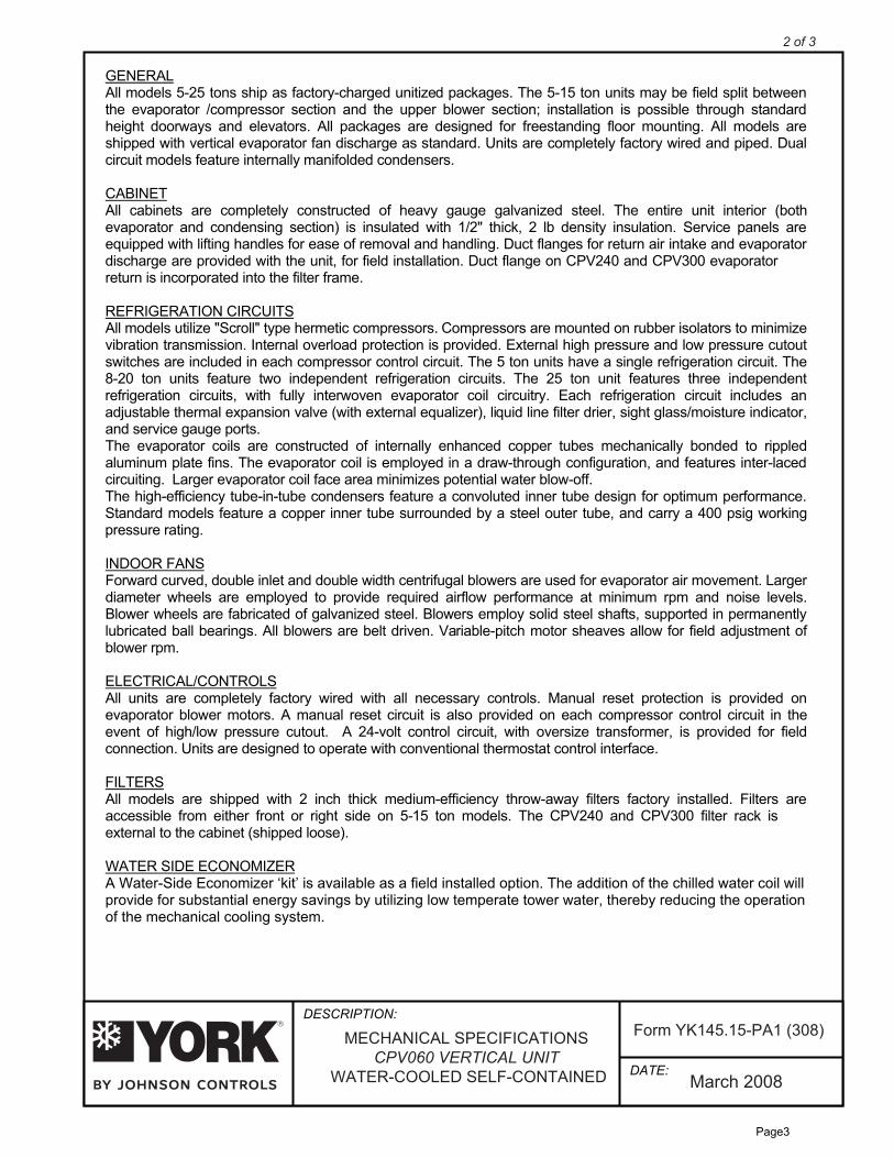
GENERALAll models 5-25 tons ship as factory-charged unitized packages. The 5-15 ton units may be field split betweenthe evaporator /compressor section and the upper blower section; installation is possible through standardheight doorways and elevators. All packages are designed for freestanding floor mounting. All models areshipped with vertical evaporator fan discharge as standard. Units are completely factory wired and piped. Dualcircuit models feature internally manifolded condensers.
CABINETAll cabinets are completely constructed of heavy gauge galvanized steel. The entire unit interior (bothevaporator and condensing section) is insulated with 1/2" thick, 2 lb density insulation. Service panels areequipped with lifting handles for ease of removal and handling. Duct flanges for return air intake and evaporatordischarge are provided with the unit, for field installation. Duct flange on CPV240 and CPV300 evaporatorreturn is incorporated into the filter frame.
REFRIGERATION CIRCUITSAll models utilize "Scroll" type hermetic compressors. Compressors are mounted on rubber isolators to minimizevibration transmission. Internal overload protection is provided. External high pressure and low pressure cutoutswitches are included in each compressor control circuit. The 5 ton units have a single refrigeration circuit. The8-20 ton units feature two independent refrigeration circuits. The 25 ton unit features three independentrefrigeration circuits, with fully interwoven evaporator coil circuitry. Each refrigeration circuit includes anadjustable thermal expansion valve (with external equalizer), liquid line filter drier, sight glass/moisture indicator,and service gauge ports.The evaporator coils are constructed of internally enhanced copper tubes mechanically bonded to rippledaluminum plate fins. The evaporator coil is employed in a draw-through configuration, and features inter-lacedcircuiting. Larger evaporator coil face area minimizes potential water blow-off.The high-efficiency tube-in-tube condensers feature a convoluted inner tube design for optimum performance.Standard models feature a copper inner tube surrounded by a steel outer tube, and carry a 400 psig workingpressure rating.
INDOOR FANSForward curved, double inlet and double width centrifugal blowers are used for evaporator air movement. Largerdiameter wheels are employed to provide required airflow performance at minimum rpm and noise levels.Blower wheels are fabricated of galvanized steel. Blowers employ solid steel shafts, supported in permanentlylubricated ball bearings. All blowers are belt driven. Variable-pitch motor sheaves allow for field adjustment ofblower rpm.
ELECTRICAL/CONTROLSAll units are completely factory wired with all necessary controls. Manual reset protection is provided onevaporator blower motors. A manual reset circuit is also provided on each compressor control circuit in theevent of high/low pressure cutout. A 24-volt control circuit, with oversize transformer, is provided for fieldconnection. Units are designed to operate with conventional thermostat control interface.
FILTERSAll models are shipped with 2 inch thick medium-efficiency throw-away filters factory installed. Filters areaccessible from either front or right side on 5-15 ton models. The CPV240 and CPV300 filter rack isexternal to the cabinet (shipped loose).
WATER SIDE ECONOMIZERA Water-Side Economizer ‘kit’ is available as a field installed option. The addition of the chilled water coil willprovide for substantial energy savings by utilizing low temperate tower water, thereby reducing the operationof the mechanical cooling system.
March 2008
MECHANICAL SPECIFICATIONSCPV060 VERTICAL UNIT
WATER-COOLED SELF-CONTAINED
Form YK145.15-PA1 (308)
2 of 3
Page3
March 2008
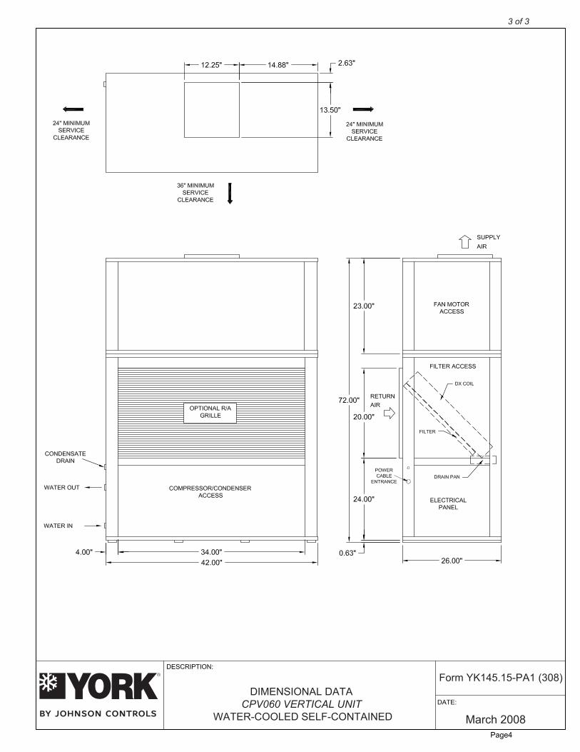
DIMENSIONAL DATACPV060 VERTICAL UNIT
WATER-COOLED SELF-CONTAINED
Form YK145.15-PA1 (308)
3 of 3
Page4

PROJECT: TAG:
Gross Cooling Capacity [Btuh]: 100,600*Design CFM: 3,200
Energy Efficiency Ratio: 13.20 EER**Net Cooling Capacity [Btuh]: 98,000**Net Cooling CFM: 3,200
Compressor No./Type: 2/ScrollRefrigerant Circuits: 2/IndependentEvaporator Fan No./Type: 1/CENTRIFUGAL
Diameter x Width [in]: 15x12Drive: Adjustable BeltMotor HP : 1.5/2[Standard/Oversized]
Operating Weight[lbs.]: 775Shipping Weight[lbs.]: 815
Condensate Connection: ¾ NPT
Johnson Controls maintains a continuous product improvement policy, therefore specifications are subject to change without notice.
COOLING PERFORMANCE DATA
STANDARD / OVERSIZED EVAPORATOR MOTORS – ELECTRICAL DATA
SUPPLY AIR BLOWER PERFORMANCE
Condenser Type:Number Used/Tons Capacity:
Coaxial2/4
Nominal Water Flow Rate [GPM]:Condenser Water Connections:
241 –1/4” FPT
TC ]hBM[ yticapaC gnilooC latoT - SC- Sensible Cooling Capacity [MBh] kW- Compressor Power [kW]
MPG 42MPG 51CPV096
CPV096
65°F EWT 85°F EWT 105°F EWT 65°F EWT 85°F EWT 105°F EWTEWB EDB TC SC kW TC SC kW TC SC kW TC SC kW TC SC kW TC SC kW
75°F 99.0 78.9 4.44 93.9 76.4 5.65 87.2 73.4 7.22 100.3 79.3 4.21 94.9 76.8 5.38 88.5 74.0 6.8762°F 80°F 99.0 93.9 4.44 93.9 91.5 5.65 87.2 87.2 7.22 100.3 94.7 4.21 94.9 92.0 5.38 88.5 88.3 6.87
85°F 104.2 104.2 4.50 98.8 98.8 5.71 92.4 92.4 7.32 105.4 105.4 4.25 100.0 100.0 5.44 93.8 93.8 6.9175°F 105.9 62.3 4.47 99.1 59.4 5.69 91.4 56.2 7.26 107.3 62.9 4.24 100.6 60.1 5.41 93.1 56.9 6.88
67°F 80°F 105.9 77.5 4.47 99.1 74.6 5.69 91.4 71.5 7.26 107.3 78.0 4.24 100.6 75.2 5.41 93.1 72.2 6.8885°F 105.9 93.2 4.47 99.1 90.2 5.69 91.4 86.8 7.26 107.3 93.8 4.24 100.6 91.0 5.41 93.1 87.8 6.8875°F 113.6 45.7 4.54 106.5 43.9 5.76 98.3 40.9 7.33 115.3 46.4 4.28 108.2 44.7 5.43 100.4 41.8 6.93
72°F 80°F 113.6 61.2 4.54 106.5 58.4 5.76 98.3 55.3 7.33 115.3 61.8 4.28 108.2 59.1 5.43 100.4 56.2 6.9385°F 113.6 76.3 4.54 106.5 73.6 5.76 98.3 70.6 7.33 115.3 76.9 4.28 108.2 74.3 5.43 100.4 71.5 6.93
3200 CFM
MODEL VOLTAGE COMPRESSOR EVAPORATOR MIN. CCT. MAX FUSE / # QTY RLA LRA HP FLA RPM AMPACITY CCT. BKR. AMP
208-230/3/60 2 @ 13.9 88.0 1.50 4.5 1800 35.78 45460/3/60 2 @ 7.1 44.0 1.50 2.2 1800 18.18 25575/3/60 2 @ 5.4 34.0 1.50 1.8 1800 13.95 15
208-230/3/60 2 @ 13.9 88.0 2.00 6.0 1800 37.28 50460/3/60 2 @ 7.1 44.0 2.00 3.0 1800 18.98 25575/3/60 2 @ 5.4 34.0 2.00 2.4 1800 14.55 15
MODEL SUPPLY 0.2 0.4 0.6 0.8 1.0 1.2 1.4 1.6
# CFM RPM BHP RPM BHP RPM BHP RPM BHP RPM BHP RPM BHP RPM BHP RPM BHP RPM BHP RPM BHP
3000
3200
568 0.70 628 0.81 688 0.92 746 1.05 801 1.19 855 1.35 906 1.50 954 1.65 1001 1.81 1046 1.97
594 0.82 651 0.94 707 1.06 762 1.19 816 1.33 867 1.49 917 1.65 964 1.81 1010 1.98 - -
3400 625 0.97 679 1.10 731 1.22 784 1.35 835 1.50 884 1.66 933 1.83 979 2.00 - - - -
1.8 2.0
EXTERNAL STATIC PRESSURE - Inches W.C.
CPV096
CPV096
UNIT SPECIFICATIONSCPV096 VERTICAL UNIT
WATER-COOLED SELF-CONTAINED
1 of 3
Form YK145.15-PA2 (308)
DATE:
DESCRIPTION:
8
March 200Refrigerant: R22Charge: 4.19 Lbs./circuit
Evaporator Coil Face Area: 9.37 [sq ft]Rows/FPI: 3/13Refrigerant Control: TX Valve
Filter No./Size: 4/14x25x2
NOTE:1. At higher evaporator air flows, and wet bulb conditions condensate carry-over may occur. Adjust airflow downward as necessary.2. Values include pressure drop from wet coil and clean filters.3. Shaded areas indicate oversize motors.
* Cooling performance is rated at 80°F dry bulb, 67°F wet bulb entering air temperature, CFM listed. 85°F entering, 95°F leaving water temperature, and water flow listed. Gross capacity does not include the effect of fan motor heat.** Rated in accordance with ARI Standard 360.
Page5

DATE:
DESCRIPTION:
GENERALAll models 5-25 tons ship as factory-charged unitized packages. The 5-15 ton units may be field split betweenthe evaporator /compressor section and the upper blower section; installation is possible through standardheight doorways and elevators. All packages are designed for freestanding floor mounting. All models areshipped with vertical evaporator fan discharge as standard. Units are completely factory wired and piped. Dualcircuit models feature internally manifolded condensers.
CABINETAll cabinets are completely constructed of heavy gauge galvanized steel. The entire unit interior (bothevaporator and condensing section) is insulated with 1/2" thick, 2 lb density insulation. Service panels areequipped with lifting handles for ease of removal and handling. Duct flanges for return air intake and evaporatordischarge are provided with the unit, for field installation. Duct flange on CPV240 and CPV300 evaporatorreturn is incorporated into the filter frame.
REFRIGERATION CIRCUITSAll models utilize "Scroll" type hermetic compressors. Compressors are mounted on rubber isolators to minimizevibration transmission. Internal overload protection is provided. External high pressure and low pressure cutoutswitches are included in each compressor control circuit. The 5 ton units have a single refrigeration circuit. The8-20 ton units feature two independent refrigeration circuits. The 25 ton unit features three independentrefrigeration circuits, with fully interwoven evaporator coil circuitry. Each refrigeration circuit includes anadjustable thermal expansion valve (with external equalizer), liquid line filter drier, sight glass/moisture indicator,and service gauge ports.The evaporator coils are constructed of internally enhanced copper tubes mechanically bonded to rippledaluminum plate fins. The evaporator coil is employed in a draw-through configuration, and features inter-lacedcircuiting. Larger evaporator coil face area minimizes potential water blow-off.The high-efficiency tube-in-tube condensers feature a convoluted inner tube design for optimum performance.Standard models feature a copper inner tube surrounded by a steel outer tube, and carry a 400 psig workingpressure rating.
INDOOR FANSForward curved, double inlet and double width centrifugal blowers are used for evaporator air movement. Largerdiameter wheels are employed to provide required airflow performance at minimum rpm and noise levels.Blower wheels are fabricated of galvanized steel. Blowers employ solid steel shafts, supported in permanentlylubricated ball bearings. All blowers are belt driven. Variable-pitch motor sheaves allow for field adjustment ofblower rpm.
ELECTRICAL/CONTROLSAll units are completely factory wired with all necessary controls. Manual reset protection is provided onevaporator blower motors. A manual reset circuit is also provided on each compressor control circuit in theevent of high/low pressure cutout. A 24-volt control circuit, with oversize transformer, is provided for fieldconnection. Units are designed to operate with conventional thermostat control interface.
FILTERSAll models are shipped with 2 inch thick medium-efficiency throw-away filters factory installed. Filters areaccessible from either front or right side on 5-15 ton models. The CPV240 and CPV300 filter rack isexternal to the cabinet (shipped loose).
WATER SIDE ECONOMIZERA Water-Side Economizer ‘kit’ is available as a field installed option. The addition of the chilled water coil willprovide for substantial energy savings by utilizing low temperate tower water, thereby reducing the operationof the mechanical cooling system.
March 2008
MECHANICAL SPECIFICATIONSCPV096 VERTICAL UNIT
WATER-COOLED SELF-CONTAINED
Form YK145.15-PA2 (308)
2 of 3
Page6
March 2008
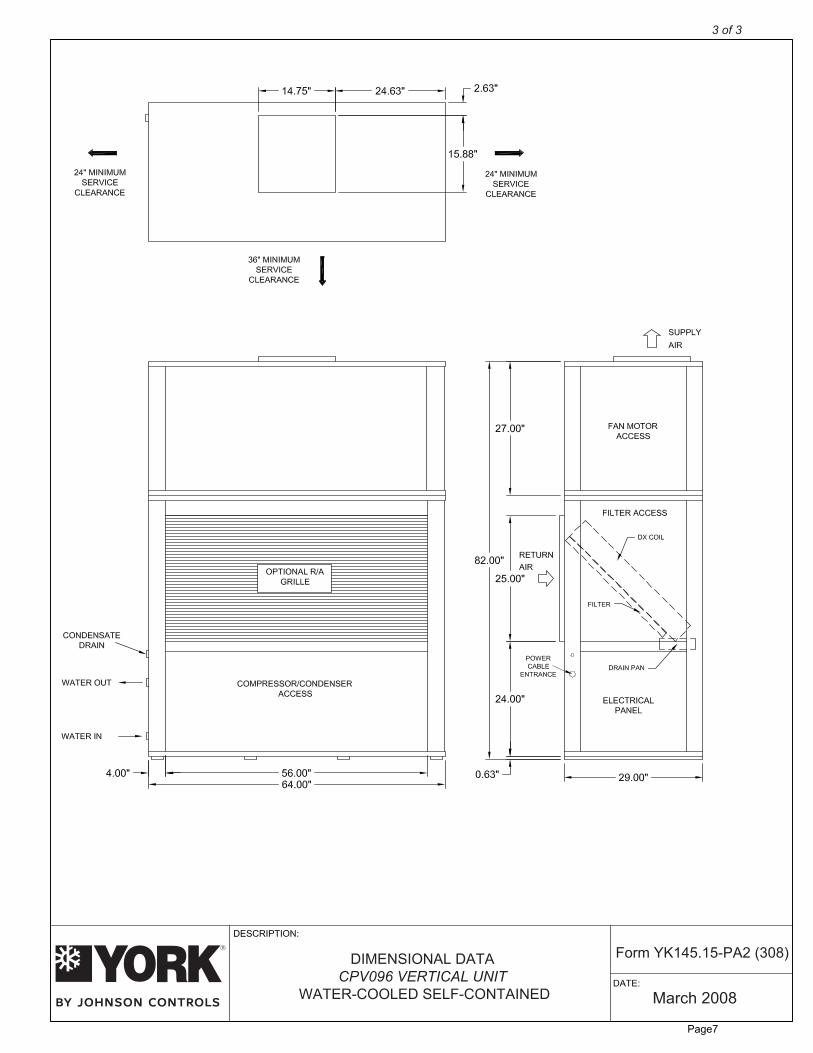
DIMENSIONAL DATACPV096 VERTICAL UNIT
WATER-COOLED SELF-CONTAINED
Form YK145.15-PA2 (308)
3 of 3
Page7
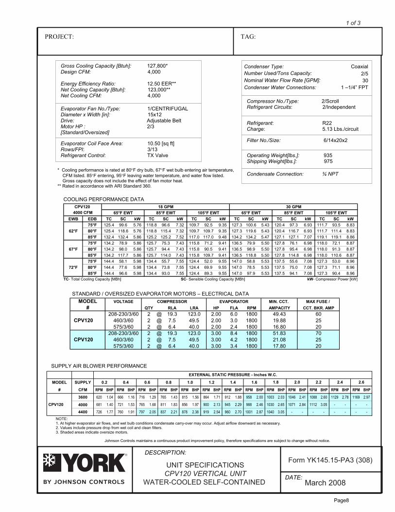
PROJECT: TAG:
Gross Cooling Capacity [Btuh]: 127,800*Design CFM: 4,000
Energy Efficiency Ratio: 12.50 EER**Net Cooling Capacity [Btuh]: 123,000**Net Cooling CFM: 4,000
Compressor No./Type: 2/ScrollRefrigerant Circuits: 2/IndependentEvaporator Fan No./Type: 1/CENTRIFUGAL
Diameter x Width [in]: 15x12Drive: Adjustable BeltMotor HP : 2/3[Standard/Oversized]
Operating Weight[lbs.]: 935Shipping Weight[lbs.]: 975
Condensate Connection: ¾ NPT
Johnson Controls maintains a continuous product improvement policy, therefore specifications are subject to change without notice.
COOLING PERFORMANCE DATA
STANDARD / OVERSIZED EVAPORATOR MOTORS – ELECTRICAL DATA
SUPPLY AIR BLOWER PERFORMANCE
Condenser Type:Number Used/Tons Capacity:
Coaxial2/5
Nominal Water Flow Rate [GPM]:Condenser Water Connections:
301 –1/4” FPT
TC ]hBM[ yticapaC gnilooC latoT - SC- Sensible Cooling Capacity [MBh] kW- Compressor Power [kW]
MPG 03MPG 81CPV12065°F EWT 85°F EWT 105°F EWT 65°F EWT 85°F EWT 105°F EWT
EWB EDB TC SC kW TC SC kW TC SC kW TC SC kW TC SC kW TC SC kW75°F 125.4 99.6 5.76 118.8 96.6 7.32 109.7 92.5 9.35 127.3 100.6 5.43 120.4 97.3 6.93 111.7 93.5 8.83
62°F 80°F 125.4 118.6 5.76 118.8 115.4 7.32 109.7 109.7 9.35 127.3 119.6 5.43 120.4 116.7 6.93 111.7 111.4 8.8385°F 132.4 132.4 5.86 125.2 125.2 7.52 117.0 117.0 9.48 134.2 134.2 5.47 127.1 127.1 7.07 119.1 119.1 8.8675°F 134.2 78.9 5.86 125.7 75.3 7.43 115.8 71.2 9.41 136.5 79.9 5.50 127.8 76.1 6.98 118.0 72.1 8.87
67°F 80°F 134.2 98.0 5.86 125.7 94.4 7.43 115.8 90.5 9.41 136.5 98.9 5.50 127.8 95.4 6.98 118.0 91.3 8.8785°F 134.2 117.7 5.86 125.7 114.0 7.43 115.8 109.7 9.41 136.5 118.8 5.50 127.8 114.8 6.98 118.0 110.6 8.8775°F 144.4 58.1 5.98 134.4 55.7 7.55 124.4 52.0 9.55 147.0 58.8 5.53 137.5 55.6 7.08 127.3 53.0 8.96
72°F 80°F 144.4 77.6 5.98 134.4 73.8 7.55 124.4 69.9 9.55 147.0 78.5 5.53 137.5 75.0 7.08 127.3 71.1 8.9685°F 144.4 96.6 5.98 134.4 93.0 7.55 124.4 89.3 9.55 147.0 97.9 5.53 137.5 94.1 7.08 127.3 90.4 8.96
4000 CFM
MODEL VOLTAGE COMPRESSOR EVAPORATOR MIN. CCT. MAX FUSE / # QTY RLA LRA HP FLA RPM AMPACITY CCT. BKR. AMP
208-230/3/60 2 @ 19.3 123.0 2.00 6.0 1800 49.43 60460/3/60 2 @ 7.5 49.5 2.00 3.0 1800 19.88 25575/3/60 2 @ 6.4 40.0 2.00 2.4 1800 16.80 20
208-230/3/60 2 @ 19.3 123.0 3.00 8.4 1800 51.83 70460/3/60 2 @ 7.5 49.5 3.00 4.2 1800 21.08 25575/3/60 2 @ 6.4 40.0 3.00 3.4 1800 17.80 20
CPV120
CPV120
MODEL SUPPLY 0.2 0.4 0.6 0.8 1.0 1.2 1.4 1.6
# CFM RPM BHP RPM BHP RPM BHP RPM BHP RPM BHP RPM BHP RPM BHP RPM BHP RPM BHP RPM BHP RPM BHP RPM BHP RPM BHP
3600
4000
620 1.04 666 1.16 716 1.29 765 1.43 815 1.56 864 1.71 912 1.88 958 2.00 1003 2.03 1046 2.41 1088 2.60 1129 2.78 1169 2.97
CPV120 681 1.40 721 1.53 765 1.68 811 1.83 856 1.97 900 2.13 945 2.29 988 2.46 1030 2.65 1071 2.84 1112 3.05 - - - -
4400 726 1.77 760 1.91 797 2.05 837 2.21 878 2.38 919 2.54 960 2.70 1001 2.87 1040 3.05 - - - - - - - -
1.8 2.0 2.2 2.4 2.6
EXTERNAL STATIC PRESSURE - Inches W.C.
UNIT SPECIFICATIONSCPV120 VERTICAL UNIT
WATER-COOLED SELF-CONTAINED
1 of 3
Form YK145.15-PA3 (308)
DATE:
DESCRIPTION:
8
March 200Refrigerant: R22Charge: 5.13 Lbs./circuit
Evaporator Coil Face Area: 10.50 [sq ft]Rows/FPI: 3/13Refrigerant Control: TX Valve
Filter No./Size: 6/14x20x2
NOTE:1. At higher evaporator air flows, and wet bulb conditions condensate carry-over may occur. Adjust airflow downward as necessary.2. Values include pressure drop from wet coil and clean filters.3. Shaded areas indicate oversize motors.
* Cooling performance is rated at 80°F dry bulb, 67°F wet bulb entering air temperature, CFM listed. 85°F entering, 95°F leaving water temperature, and water flow listed. Gross capacity does not include the effect of fan motor heat.** Rated in accordance with ARI Standard 360.
Page8

DATE:
DESCRIPTION:
GENERALAll models 5-25 tons ship as factory-charged unitized packages. The 5-15 ton units may be field split betweenthe evaporator /compressor section and the upper blower section; installation is possible through standardheight doorways and elevators. All packages are designed for freestanding floor mounting. All models areshipped with vertical evaporator fan discharge as standard. Units are completely factory wired and piped. Dualcircuit models feature internally manifolded condensers.
CABINETAll cabinets are completely constructed of heavy gauge galvanized steel. The entire unit interior (bothevaporator and condensing section) is insulated with 1/2" thick, 2 lb density insulation. Service panels areequipped with lifting handles for ease of removal and handling. Duct flanges for return air intake and evaporatordischarge are provided with the unit, for field installation. Duct flange on CPV240 and CPV300 evaporatorreturn is incorporated into the filter frame.
REFRIGERATION CIRCUITSAll models utilize "Scroll" type hermetic compressors. Compressors are mounted on rubber isolators to minimizevibration transmission. Internal overload protection is provided. External high pressure and low pressure cutoutswitches are included in each compressor control circuit. The 5 ton units have a single refrigeration circuit. The8-20 ton units feature two independent refrigeration circuits. The 25 ton unit features three independentrefrigeration circuits, with fully interwoven evaporator coil circuitry. Each refrigeration circuit includes anadjustable thermal expansion valve (with external equalizer), liquid line filter drier, sight glass/moisture indicator,and service gauge ports.The evaporator coils are constructed of internally enhanced copper tubes mechanically bonded to rippledaluminum plate fins. The evaporator coil is employed in a draw-through configuration, and features inter-lacedcircuiting. Larger evaporator coil face area minimizes potential water blow-off.The high-efficiency tube-in-tube condensers feature a convoluted inner tube design for optimum performance.Standard models feature a copper inner tube surrounded by a steel outer tube, and carry a 400 psig workingpressure rating.
INDOOR FANSForward curved, double inlet and double width centrifugal blowers are used for evaporator air movement. Largerdiameter wheels are employed to provide required airflow performance at minimum rpm and noise levels.Blower wheels are fabricated of galvanized steel. Blowers employ solid steel shafts, supported in permanentlylubricated ball bearings. All blowers are belt driven. Variable-pitch motor sheaves allow for field adjustment ofblower rpm.
ELECTRICAL/CONTROLSAll units are completely factory wired with all necessary controls. Manual reset protection is provided onevaporator blower motors. A manual reset circuit is also provided on each compressor control circuit in theevent of high/low pressure cutout. A 24-volt control circuit, with oversize transformer, is provided for fieldconnection. Units are designed to operate with conventional thermostat control interface.
FILTERSAll models are shipped with 2 inch thick medium-efficiency throw-away filters factory installed. Filters areaccessible from either front or right side on 5-15 ton models. The CPV240 and CPV300 filter rack isexternal to the cabinet (shipped loose).
WATER SIDE ECONOMIZERA Water-Side Economizer ‘kit’ is available as a field installed option. The addition of the chilled water coil willprovide for substantial energy savings by utilizing low temperate tower water, thereby reducing the operationof the mechanical cooling system.
March 2008
MECHANICAL SPECIFICATIONSCPV120 VERTICAL UNIT
WATER-COOLED SELF-CONTAINED
Form YK145.15-PA3 (308)
2 of 3
Page9

March 2008
DIMENSIONAL DATACPV120 VERTICAL UNIT
WATER-COOLED SELF-CONTAINED
Form YK145.15-PA3 (308)
3 of 3
Page10
DATE:
DESCRIPTION:
PROJECT: TAG:
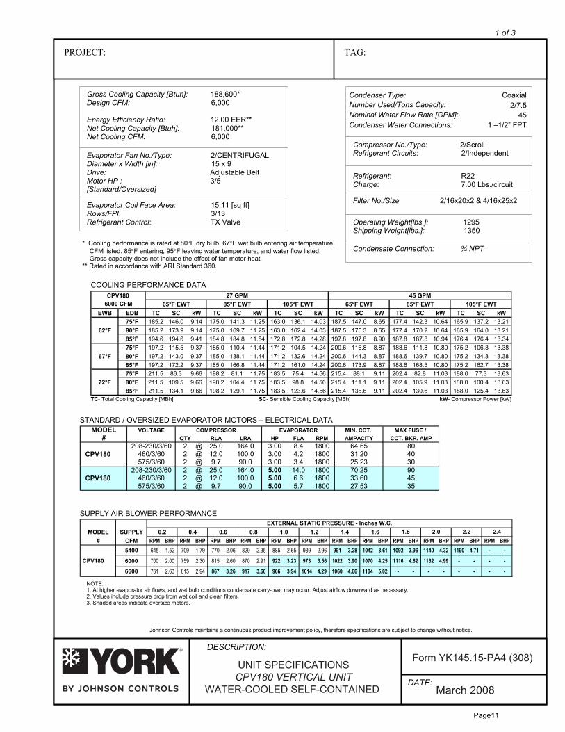
Gross Cooling Capacity [Btuh]: 188,600*Design CFM: 6,000
Energy Efficiency Ratio: 12.00 EER**Net Cooling Capacity [Btuh]: 181,000**Net Cooling CFM: 6,000
Refrigerant: R22Charge: 7.00 Lbs./circuit
Compressor No./Type: 2/ScrollRefrigerant Circuits: 2/Independent
Evaporator Coil Face Area: 15.11 [sq ft]Rows/FPI: 3/13Refrigerant Control: TX Valve
Filter No./Size 2/16x20x2 & 4/16x25x2
Evaporator Fan No./Type: 2/CENTRIFUGALDiameter x Width [in]: 15 x 9Drive: Adjustable BeltMotor HP : 3/5[Standard/Oversized]
Operating Weight[lbs.]: 1295Shipping Weight[lbs.]: 1350
Condensate Connection: ¾ NPT
NOTE:1. At higher evaporator air flows, and wet bulb conditions condensate carry-over may occur. Adjust airflow downward as necessary.2. Values include pressure drop from wet coil and clean filters.3. Shaded areas indicate oversize motors.
* Cooling performance is rated at 80°F dry bulb, 67°F wet bulb entering air temperature, CFM listed. 85°F entering, 95°F leaving water temperature, and water flow listed. Gross capacity does not include the effect of fan motor heat.** Rated in accordance with ARI Standard 360.
Johnson Controls maintains a continuous product improvement policy, therefore specifications are subject to change without notice.
COOLING PERFORMANCE DATA
STANDARD / OVERSIZED EVAPORATOR MOTORS – ELECTRICAL DATA
SUPPLY AIR BLOWER PERFORMANCE
Condenser Type:Number Used/Tons Capacity:
Coaxial2/7.5
Nominal Water Flow Rate [GPM]:Condenser Water Connections:
451 –1/2” FPT
TC ]hBM[ yticapaC gnilooC latoT - SC- Sensible Cooling Capacity [MBh] kW- Compressor Power [kW]
MPG 54MPG 72CPV18065°F EWT 85°F EWT 105°F EWT 65°F EWT 85°F EWT 105°F EWT
EWB EDB TC SC kW TC SC kW TC SC kW TC SC kW TC SC kW TC SC kW75°F 185.2 146.0 9.14 175.0 141.3 11.25 163.0 136.1 14.03 187.5 147.0 8.65 177.4 142.3 10.64 165.9 137.2 13.21
62°F 80°F 185.2 173.9 9.14 175.0 169.7 11.25 163.0 162.4 14.03 187.5 175.3 8.65 177.4 170.2 10.64 165.9 164.0 13.2185°F 194.6 194.6 9.41 184.8 184.8 11.54 172.8 172.8 14.28 197.8 197.8 8.90 187.8 187.8 10.94 176.4 176.4 13.3475°F 197.2 115.5 9.37 185.0 110.4 11.44 171.2 104.5 14.24 200.6 116.8 8.87 188.6 111.8 10.80 175.2 106.3 13.38
67°F 80°F 197.2 143.0 9.37 185.0 138.1 11.44 171.2 132.6 14.24 200.6 144.3 8.87 188.6 139.7 10.80 175.2 134.3 13.3885°F 197.2 172.2 9.37 185.0 166.8 11.44 171.2 161.0 14.24 200.6 173.9 8.87 188.6 168.5 10.80 175.2 162.7 13.3875°F 211.5 86.3 9.66 198.2 81.1 11.75 183.5 75.4 14.56 215.4 88.1 9.11 202.4 82.8 11.03 188.0 77.3 13.63
72°F 80°F 211.5 109.5 9.66 198.2 104.4 11.75 183.5 98.8 14.56 215.4 111.1 9.11 202.4 105.9 11.03 188.0 100.4 13.6385°F 211.5 134.1 9.66 198.2 129.1 11.75 183.5 123.6 14.56 215.4 135.6 9.11 202.4 130.6 11.03 188.0 125.4 13.63
6000 CFM
MODEL SUPPLY 0.2 0.4 0.6 0.8 1.0 1.2 1.4 1.6# CFM RPM BHP RPM BHP RPM BHP RPM BHP RPM BHP RPM BHP RPM BHP RPM BHP RPM BHP RPM BHP RPM BHP RPM BHP
5400 645 1.52 709 1.79 770 2.06 829 2.35 885 2.65 939 2.96 991 3.28 1042 3.61 1092 3.96 1140 4.32 1190 4.71 - -
CPV180 700 2.00 759 2.30 815 2.60 870 2.91 922 3.23 973 3.56 1022 3.90 1070 4.25 1116 4.62 1162 4.99 - - - -
6600
6000
761 2.63 815 2.94 867 3.26 917 3.60 966 3.94 1014 4.29 1060 4.66 1104 5.02 - - - - - - - -
1.8 2.0 2.2 2.4EXTERNAL STATIC PRESSURE - Inches W.C.
MODEL VOLTAGE COMPRESSOR EVAPORATOR MIN. CCT. MAX FUSE / # QTY RLA LRA HP FLA RPM AMPACITY CCT. BKR. AMP
208-230/3/60 2 @ 25.0 164.0 3.00 8.4 1800 64.65 80460/3/60 2 @ 12.0 100.0 3.00 4.2 1800 31.20 40575/3/60 2 @ 9.7 90.0 3.00 3.4 1800 25.23 30
208-230/3/60 2 @ 25.0 164.0 5.00 14.0 1800 70.25 90460/3/60 2 @ 12.0 100.0 5.00 6.6 1800 33.60 45575/3/60 2 @ 9.7 90.0 5.00 5.7 1800 27.53 35
CPV180
CPV180
March 2008
UNIT SPECIFICATIONSCPV180 VERTICAL UNIT
WATER-COOLED SELF-CONTAINED
Form YK145.15-PA4 (308)
1 of 3
Page11
DATE:
DESCRIPTION:
GENERALAll models 5-25 tons ship as factory-charged unitized packages. The 5-15 ton units may be field split betweenthe evaporator /compressor section and the upper blower section; installation is possible through standardheight doorways and elevators. All packages are designed for freestanding floor mounting. All models areshipped with vertical evaporator fan discharge as standard. Units are completely factory wired and piped. Dualcircuit models feature internally manifolded condensers.
CABINETAll cabinets are completely constructed of heavy gauge galvanized steel. The entire unit interior (bothevaporator and condensing section) is insulated with 1/2" thick, 2 lb density insulation. Service panels areequipped with lifting handles for ease of removal and handling. Duct flanges for return air intake and evaporatordischarge are provided with the unit, for field installation. Duct flange on CPV240 and CPV300 evaporatorreturn is incorporated into the filter frame.
REFRIGERATION CIRCUITSAll models utilize "Scroll" type hermetic compressors. Compressors are mounted on rubber isolators to minimizevibration transmission. Internal overload protection is provided. External high pressure and low pressure cutoutswitches are included in each compressor control circuit. The 5 ton units have a single refrigeration circuit. The8-20 ton units feature two independent refrigeration circuits. The 25 ton unit features three independentrefrigeration circuits, with fully interwoven evaporator coil circuitry. Each refrigeration circuit includes anadjustable thermal expansion valve (with external equalizer), liquid line filter drier, sight glass/moisture indicator,and service gauge ports.The evaporator coils are constructed of internally enhanced copper tubes mechanically bonded to rippledaluminum plate fins. The evaporator coil is employed in a draw-through configuration, and features inter-lacedcircuiting. Larger evaporator coil face area minimizes potential water blow-off.The high-efficiency tube-in-tube condensers feature a convoluted inner tube design for optimum performance.Standard models feature a copper inner tube surrounded by a steel outer tube, and carry a 400 psig workingpressure rating.
INDOOR FANSForward curved, double inlet and double width centrifugal blowers are used for evaporator air movement. Largerdiameter wheels are employed to provide required airflow performance at minimum rpm and noise levels.Blower wheels are fabricated of galvanized steel. Blowers employ solid steel shafts, supported in permanentlylubricated ball bearings. All blowers are belt driven. Variable-pitch motor sheaves allow for field adjustment ofblower rpm.
ELECTRICAL/CONTROLSAll units are completely factory wired with all necessary controls. Manual reset protection is provided onevaporator blower motors. A manual reset circuit is also provided on each compressor control circuit in theevent of high/low pressure cutout. A 24-volt control circuit, with oversize transformer, is provided for fieldconnection. Units are designed to operate with conventional thermostat control interface.
FILTERSAll models are shipped with 2 inch thick medium-efficiency throw-away filters factory installed. Filters areaccessible from either front or right side on 5-15 ton models. The CPV240 and CPV300 filter rack isexternal to the cabinet (shipped loose).
WATER SIDE ECONOMIZERA Water-Side Economizer ‘kit’ is available as a field installed option. The addition of the chilled water coil willprovide for substantial energy savings by utilizing low temperate tower water, thereby reducing the operationof the mechanical cooling system.
March 2008
MECHANICAL SPECIFICATIONSCPV180 VERTICAL UNIT
WATER-COOLED SELF-CONTAINED
Form YK145.15-PA4 (308)
2 of 3
Page12
March 2008
DIMENSIONAL DATACPV180 VERTICAL UNIT
WATER-COOLED SELF-CONTAINED
Form YK145.15-PA4 (308)
3 of 3
Page13
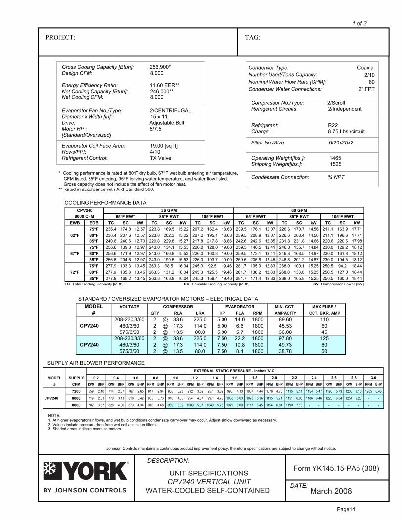
PROJECT: TAG:
Gross Cooling Capacity [Btuh]: 256,900*Design CFM: 8,000
Energy Efficiency Ratio: 11.60 EER**Net Cooling Capacity [Btuh]: 246,000**Net Cooling CFM: 8,000
Compressor No./Type: 2/ScrollRefrigerant Circuits: 2/Independent
Filter No./Size 6/20x25x2
Evaporator Fan No./Type: 2/CENTRIFUGALDiameter x Width [in]: 15 x 11Drive: Adjustable BeltMotor HP : 5/7.5[Standard/Oversized]
Operating Weight[lbs.]: 1465Shipping Weight[lbs.]: 1525
Condensate Connection: ¾ NPT
Johnson Controls maintains a continuous product improvement policy, therefore specifications are subject to change without notice.
COOLING PERFORMANCE DATA
STANDARD / OVERSIZED EVAPORATOR MOTORS – ELECTRICAL DATA
SUPPLY AIR BLOWER PERFORMANCE
Condenser Type:Number Used/Tons Capacity:
Coaxial2/10
Nominal Water Flow Rate [GPM]:Condenser Water Connections:
602” FPT
TC ]hBM[ yticapaC gnilooC latoT - SC- Sensible Cooling Capacity [MBh] kW- Compressor Power [kW]
MPG 06MPG 63CPV24065°F EWT 85°F EWT 105°F EWT 65°F EWT 85°F EWT 105°F EWT
EWB EDB TC SC kW TC SC kW TC SC kW TC SC kW TC SC kW TC SC kW75°F 236.4 174.8 12.57 223.8 169.5 15.22 207.2 162.4 18.63 239.5 176.1 12.07 226.6 170.7 14.56 211.1 163.9 17.71
62°F 80°F 236.4 207.6 12.57 223.8 202.3 15.22 207.2 195.1 18.63 239.5 208.9 12.07 226.6 203.4 14.56 211.1 196.6 17.7185°F 240.6 240.6 12.70 229.8 229.8 15.27 217.8 217.8 18.86 242.6 242.6 12.85 231.8 231.8 14.66 220.6 220.6 17.9875°F 256.6 139.3 12.97 243.0 134.1 15.53 226.0 128.0 19.00 259.5 140.5 12.41 246.8 135.7 14.84 230.0 129.2 18.12
67°F 80°F 256.6 171.9 12.97 243.0 166.8 15.53 226.0 160.8 19.00 259.5 173.1 12.41 246.8 168.5 14.87 230.0 161.8 18.1285°F 256.6 204.6 12.97 243.0 199.5 15.53 226.0 193.7 19.00 259.5 205.8 12.45 246.8 201.2 14.87 230.0 194.5 18.1275°F 277.9 103.3 13.45 263.3 98.5 16.04 245.3 92.5 19.46 281.7 105.0 12.83 268.0 100.1 15.25 250.5 94.2 18.44
72°F 80°F 277.9 135.8 13.45 263.3 131.2 16.04 245.3 125.5 19.46 281.7 138.2 12.83 268.0 133.0 15.25 250.5 127.0 18.4485°F 277.9 168.2 13.45 263.3 163.9 16.04 245.3 158.4 19.46 281.7 171.4 12.83 268.0 165.8 15.25 250.5 160.0 18.44
8000 CFM
MODEL VOLTAGE COMPRESSOR EVAPORATOR MIN. CCT. MAX FUSE / # QTY RLA LRA HP FLA RPM AMPACITY CCT. BKR. AMP
208-230/3/60 2 @ 33.6 225.0 5.00 14.0 1800 89.60 110460/3/60 2 @ 17.3 114.0 5.00 6.6 1800 45.53 60575/3/60 2 @ 13.5 80.0 5.00 5.7 1800 36.08 45
208-230/3/60 2 @ 33.6 225.0 7.50 22.2 1800 97.80 125460/3/60 2 @ 17.3 114.0 7.50 10.8 1800 49.73 60575/3/60 2 @ 13.5 80.0 7.50 8.4 1800 38.78 50
CPV240
CPV240
MODEL SUPPLY 0.2 0.4 0.6 0.8 1.0 1.2 1.4 1.6
# CFM RPM BHP RPM BHP RPM BHP RPM BHP RPM BHP RPM BHP RPM BHP RPM BHP RPM BHP RPM BHP RPM BHP RPM BHP RPM BHP RPM BHP RPM BHP
7200 659 2.10 714 2.37 767 2.65 817 2.94 866 3.23 912 3.52 957 3.82 998 4.13 1037 4.44 1076 4.76 1115 5.11 1154 5.47 1193 5.73 1230 6.10 1265 6.46
CPV240 719 2.81 770 3.11 818 3.42 865 3.73 910 4.05 954 4.37 997 4.70 1038 5.03 1078 5.36 1115 5.71 1151 6.08 1186 6.46 1220 6.84 1254 7.23 - -
8800 782 3.67 828 4.00 873 4.34 916 4.68 959 5.02 1000 5.37 1040 5.73 1079 6.09 1117 6.45 1154 6.81 1190 7.18 - - - - - - - -
EXTERNAL STATIC PRESSURE - Inches W.C.
1.8 2.0 2.2 2.4 2.6 2.8 3.0
8000
UNIT SPECIFICATIONSCPV240 VERTICAL UNIT
WATER-COOLED SELF-CONTAINED
1 of 3
Form YK145.15-PA5 (308)
DATE:
DESCRIPTION:
8
March 200Refrigerant: R22Charge: 8.75 Lbs./circuit
Evaporator Coil Face Area: 19.00 [sq ft]Rows/FPI: 4/10Refrigerant Control: TX Valve
NOTE:1. At higher evaporator air flows, and wet bulb conditions condensate carry-over may occur. Adjust airflow downward as necessary.2. Values include pressure drop from wet coil and clean filters.3. Shaded areas indicate oversize motors.
* Cooling performance is rated at 80°F dry bulb, 67°F wet bulb entering air temperature, CFM listed. 85°F entering, 95°F leaving water temperature, and water flow listed. Gross capacity does not include the effect of fan motor heat.** Rated in accordance with ARI Standard 360.
Page14

DATE:
DESCRIPTION:
GENERALAll models 5-25 tons ship as factory-charged unitized packages. The 5-15 ton units may be field split betweenthe evaporator /compressor section and the upper blower section; installation is possible through standardheight doorways and elevators. All packages are designed for freestanding floor mounting. All models areshipped with vertical evaporator fan discharge as standard. Units are completely factory wired and piped. Dualcircuit models feature internally manifolded condensers.
CABINETAll cabinets are completely constructed of heavy gauge galvanized steel. The entire unit interior (bothevaporator and condensing section) is insulated with 1/2" thick, 2 lb density insulation. Service panels areequipped with lifting handles for ease of removal and handling. Duct flanges for return air intake and evaporatordischarge are provided with the unit, for field installation. Duct flange on CPV240 and CPV300 evaporatorreturn is incorporated into the filter frame.
REFRIGERATION CIRCUITSAll models utilize "Scroll" type hermetic compressors. Compressors are mounted on rubber isolators to minimizevibration transmission. Internal overload protection is provided. External high pressure and low pressure cutoutswitches are included in each compressor control circuit. The 5 ton units have a single refrigeration circuit. The8-20 ton units feature two independent refrigeration circuits. The 25 ton unit features three independentrefrigeration circuits, with fully interwoven evaporator coil circuitry. Each refrigeration circuit includes anadjustable thermal expansion valve (with external equalizer), liquid line filter drier, sight glass/moisture indicator,and service gauge ports.The evaporator coils are constructed of internally enhanced copper tubes mechanically bonded to rippledaluminum plate fins. The evaporator coil is employed in a draw-through configuration, and features inter-lacedcircuiting. Larger evaporator coil face area minimizes potential water blow-off.The high-efficiency tube-in-tube condensers feature a convoluted inner tube design for optimum performance.Standard models feature a copper inner tube surrounded by a steel outer tube, and carry a 400 psig workingpressure rating.
INDOOR FANSForward curved, double inlet and double width centrifugal blowers are used for evaporator air movement. Largerdiameter wheels are employed to provide required airflow performance at minimum rpm and noise levels.Blower wheels are fabricated of galvanized steel. Blowers employ solid steel shafts, supported in permanentlylubricated ball bearings. All blowers are belt driven. Variable-pitch motor sheaves allow for field adjustment ofblower rpm.
ELECTRICAL/CONTROLSAll units are completely factory wired with all necessary controls. Manual reset protection is provided onevaporator blower motors. A manual reset circuit is also provided on each compressor control circuit in theevent of high/low pressure cutout. A 24-volt control circuit, with oversize transformer, is provided for fieldconnection. Units are designed to operate with conventional thermostat control interface.
FILTERSAll models are shipped with 2 inch thick medium-efficiency throw-away filters factory installed. Filters areaccessible from either front or right side on 5-15 ton models. The CPV240 and CPV300 filter rack isexternal to the cabinet (shipped loose).
WATER SIDE ECONOMIZERA Water-Side Economizer ‘kit’ is available as a field installed option. The addition of the chilled water coil willprovide for substantial energy savings by utilizing low temperate tower water, thereby reducing the operationof the mechanical cooling system.
March 2008
MECHANICAL SPECIFICATIONSCPV240 VERTICAL UNIT
WATER-COOLED SELF-CONTAINED
Form YK145.15-PA5 (308)
2 of 3
Page15

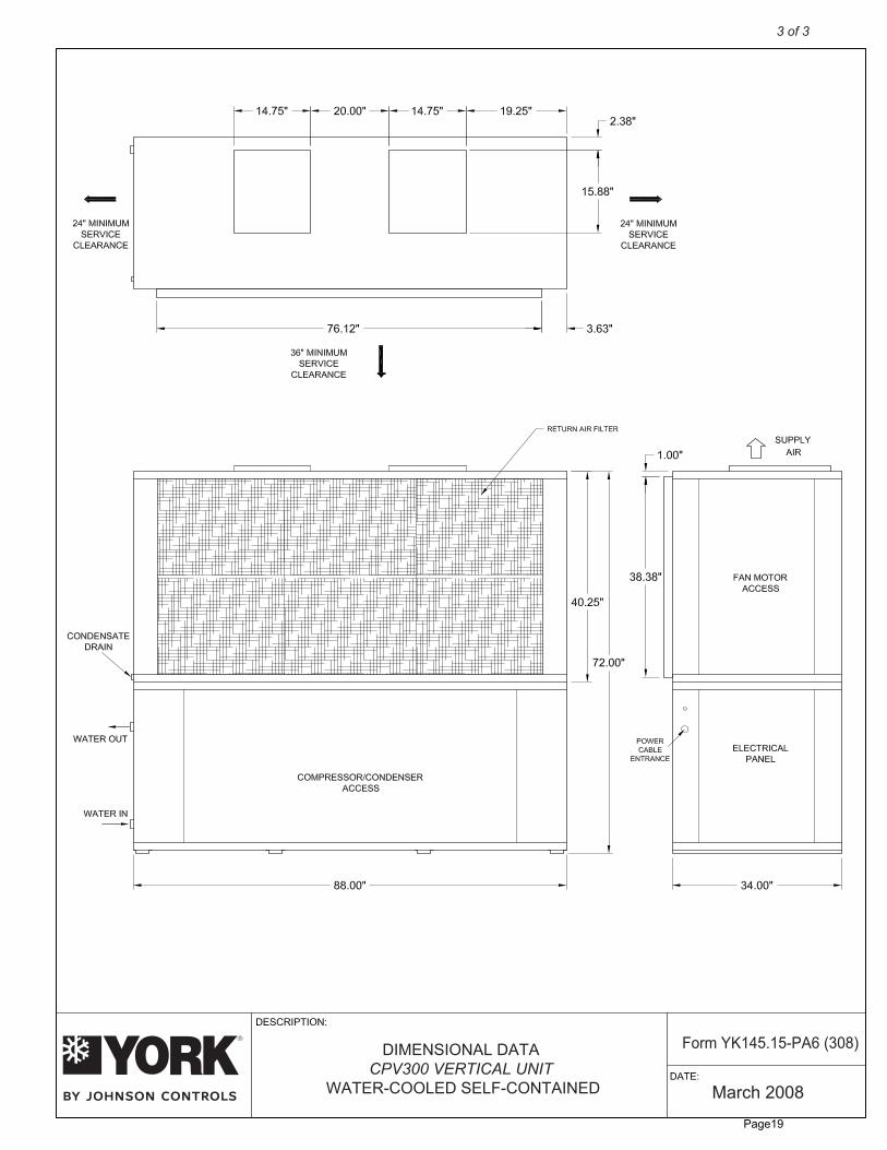
March 2008
DIMENSIONAL DATACPV240 VERTICAL UNIT
WATER-COOLED SELF-CONTAINED
Form YK145.15-PA5 (308)
3 of 3
Page16

PROJECT: TAG:
Gross Cooling Capacity [Btuh]: 321,600*Design CFM: 10,000
Energy Efficiency Ratio: 11.50 EER**Net Cooling Capacity [Btuh]: 305,000**Net Cooling CFM: 8,600
Compressor No./Type: 3/ScrollRefrigerant Circuits: 3/Independent
Filter No./Size 8/20x20x2
Evaporator Fan No./Type: 2/CENTRIFUGALDiameter x Width [in]: 15 x 11Drive: Adjustable BeltMotor HP : 7.5/10[Standard/Oversized]
Operating Weight[lbs.]: 1760Shipping Weight[lbs.]: 1825
Condensate Connection: ¾ NPT
Johnson Controls maintains a continuous product improvement policy, therefore specifications are subject to change without notice.
COOLING PERFORMANCE DATA
STANDARD / OVERSIZED EVAPORATOR MOTORS – ELECTRICAL DATA
SUPPLY AIR BLOWER PERFORMANCE
Condenser Type:Number Used/Tons Capacity:
Coaxial3/7.5
Nominal Water Flow Rate [GPM]:Condenser Water Connections:
752” FPT
TC ]hBM[ yticapaC gnilooC latoT - SC- Sensible Cooling Capacity [MBh] kW- Compressor Power [kW]
MPG 57MPG 54CPV30065°F EWT 85°F EWT 105°F EWT 65°F EWT 85°F EWT 105°F EWT
EWB EDB TC SC kW TC SC kW TC SC kW TC SC kW TC SC kW TC SC kW75°F 308.9 227.9 22.17 289.6 217.8 25.74 266.8 206.5 30.41 314.6 234.0 21.29 295.4 220.9 24.67 273.2 213.3 29.09
62°F 80°F 308.9 267.2 22.17 289.6 257.1 25.74 266.8 246.2 30.41 314.6 275.2 21.29 295.4 260.2 24.67 273.2 255.1 29.0985°F 308.9 308.9 22.17 289.6 257.1 25.74 266.8 266.8 30.41 314.6 314.6 21.29 295.4 295.4 24.67 273.2 273.2 29.0975°F 335.8 180.6 22.74 314.8 171.2 26.32 290.4 161.4 31.09 342.0 183.3 21.73 321.6 175.9 25.14 298.2 166.7 29.57
67°F 80°F 335.8 220.9 22.74 314.8 211.2 26.32 290.4 201.2 31.09 342.0 223.3 21.73 321.6 218.0 25.14 298.2 208.4 29.5785°F 335.8 260.9 22.74 314.8 251.2 26.32 290.4 241.3 31.09 342.0 263.6 21.73 321.6 259.8 25.14 298.2 250.5 29.5775°F 363.7 133.1 23.33 340.6 125.3 26.96 316.5 118.3 31.78 372.5 135.9 22.22 350.4 128.5 25.67 325.7 121.1 30.05
72°F 80°F 363.7 174.2 23.33 340.6 166.2 26.96 316.5 159.5 31.78 372.5 178.0 22.22 350.4 170.3 25.67 325.7 162.5 30.0585°F 363.7 215.6 23.33 340.6 207.0 26.96 316.5 200.9 31.78 372.5 219.7 22.22 350.4 211.9 25.67 325.7 204.2 30.05
10000 CFM
MODEL VOLTAGE COMPRESSOR EVAPORATOR MIN. CCT. MAX FUSE / # QTY RLA LRA HP FLA RPM AMPACITY CCT. BKR. AMP
208-230/3/60 3 @ 32.1 195.0 7.50 22.2 1800 126.53 150460/3/60 3 @ 16.4 95.0 7.50 10.8 1800 64.10 80575/3/60 3 @ 12.0 80.0 7.50 8.4 1800 47.40 50
208-230/3/60 3 @ 32.1 195.0 10.00 25.6 3600 129.93 150460/3/60 3 @ 16.4 95.0 10.00 11.6 3600 64.90 80575/3/60 3 @ 12.0 80.0 10.00 9.1 3600 48.10 60
CPV300
CPV300
MODEL SUPPLY 0.2 0.4 0.6 0.8 1.0 1.2 1.4 1.6
# CFM RPM BHP RPM BHP RPM BHP RPM BHP RPM BHP RPM BHP RPM BHP RPM BHP RPM BHP RPM BHP RPM BHP RPM BHP RPM BHP RPM BHP RPM BHP
9000 800 3.93 846 4.27 890 4.61 932 4.96 974 5.32 1014 5.67 1053 6.03 1092 6.40 1129 6.77 1166 7.14 1202 7.51 1237 7.90 1271 8.28 1304 8.66 1336 9.03
CPV300 878 5.29 920 5.67 960 6.05 999 6.43 1037 6.82 1074 7.21 1111 7.61 1147 8.01 1182 8.41 1216 8.82 1250 9.22 1283 9.63 1315 10.04 - - - -
11000
10000
958 6.95 996 7.37 1033 7.79 1069 8.21 1104 8.63 1139 9.05 1173 9.48 1206 9.92 - - - - - - - - - - - - - -
EXTERNAL STATIC PRESSURE - Inches W.C.
1.8 2.0 2.2 2.4 2.6 2.8 3.0
UNIT SPECIFICATIONSCPV300 VERTICAL UNIT
WATER-COOLED SELF-CONTAINED
1 of 3
Form YK145.15-PA6 (308)
DATE:
DESCRIPTION:
8
March 200Refrigerant: R22Charge: 7.50 Lbs./circuit
Evaporator Coil Face Area: 19.79 [sq ft]Rows/FPI: 4/10Refrigerant Control: TX Valve
NOTE:1. At higher evaporator air flows, and wet bulb conditions condensate carry-over may occur. Adjust airflow downward as necessary.2. Values include pressure drop from wet coil and clean filters.3. Shaded areas indicate oversize motors.
* Cooling performance is rated at 80°F dry bulb, 67°F wet bulb entering air temperature, CFM listed. 85°F entering, 95°F leaving water temperature, and water flow listed. Gross capacity does not include the effect of fan motor heat.** Rated in accordance with ARI Standard 360.
Page17
DATE:
DESCRIPTION:
GENERALAll models 5-25 tons ship as factory-charged unitized packages. The 5-15 ton units may be field split betweenthe evaporator /compressor section and the upper blower section; installation is possible through standardheight doorways and elevators. All packages are designed for freestanding floor mounting. All models areshipped with vertical evaporator fan discharge as standard. Units are completely factory wired and piped. Dualcircuit models feature internally manifolded condensers.
CABINETAll cabinets are completely constructed of heavy gauge galvanized steel. The entire unit interior (bothevaporator and condensing section) is insulated with 1/2" thick, 2 lb density insulation. Service panels areequipped with lifting handles for ease of removal and handling. Duct flanges for return air intake and evaporatordischarge are provided with the unit, for field installation. Duct flange on CPV240 and CPV300 evaporatorreturn is incorporated into the filter frame.
REFRIGERATION CIRCUITSAll models utilize "Scroll" type hermetic compressors. Compressors are mounted on rubber isolators to minimizevibration transmission. Internal overload protection is provided. External high pressure and low pressure cutoutswitches are included in each compressor control circuit. The 5 ton units have a single refrigeration circuit. The8-20 ton units feature two independent refrigeration circuits. The 25 ton unit features three independentrefrigeration circuits, with fully interwoven evaporator coil circuitry. Each refrigeration circuit includes anadjustable thermal expansion valve (with external equalizer), liquid line filter drier, sight glass/moisture indicator,and service gauge ports.The evaporator coils are constructed of internally enhanced copper tubes mechanically bonded to rippledaluminum plate fins. The evaporator coil is employed in a draw-through configuration, and features inter-lacedcircuiting. Larger evaporator coil face area minimizes potential water blow-off.The high-efficiency tube-in-tube condensers feature a convoluted inner tube design for optimum performance.Standard models feature a copper inner tube surrounded by a steel outer tube, and carry a 400 psig workingpressure rating.
INDOOR FANSForward curved, double inlet and double width centrifugal blowers are used for evaporator air movement. Largerdiameter wheels are employed to provide required airflow performance at minimum rpm and noise levels.Blower wheels are fabricated of galvanized steel. Blowers employ solid steel shafts, supported in permanentlylubricated ball bearings. All blowers are belt driven. Variable-pitch motor sheaves allow for field adjustment ofblower rpm.
ELECTRICAL/CONTROLSAll units are completely factory wired with all necessary controls. Manual reset protection is provided onevaporator blower motors. A manual reset circuit is also provided on each compressor control circuit in theevent of high/low pressure cutout. A 24-volt control circuit, with oversize transformer, is provided for fieldconnection. Units are designed to operate with conventional thermostat control interface.
FILTERSAll models are shipped with 2 inch thick medium-efficiency throw-away filters factory installed. Filters areaccessible from either front or right side on 5-15 ton models. The CPV240 and CPV300 filter rack isexternal to the cabinet (shipped loose).
WATER SIDE ECONOMIZERA Water-Side Economizer ‘kit’ is available as a field installed option. The addition of the chilled water coil willprovide for substantial energy savings by utilizing low temperate tower water, thereby reducing the operationof the mechanical cooling system.
March 2008
MECHANICAL SPECIFICATIONSCPV300 VERTICAL UNIT
WATER-COOLED SELF-CONTAINED
Form YK145.15-PA6 (308)
2 of 3
Page18
March 2008
DIMENSIONAL DATACPV300 VERTICAL UNIT
WATER-COOLED SELF-CONTAINED
Form YK145.15-PA6 (308)
3 of 3
Page19


