9
Continuum Voltage Converter User’s Guide This User’s Guide is for First and Second Generation CVC 2015-08-19 Firmware Version 7 Edmund Eagan and Lippold Haken

C o n t i n u u m V o l t a g e C o n v e r t e rU s e r ’ s G u i d e
This User’s Guide is for First and Second Generation CVC 2015-08-19
Firmware Version 7
Edmund Eagan and Lippold Haken
H a k e n A u d i o - C V C U s e r ’ s G u i d e
About this document The current version of this document can be found online in the Resources area of www.HakenAudio.com. We suggest new Continuum Fingerboard owners read this guide in its entirety. The knowledge you gain will save you time in the future and significantly enhance your experience with your Continuum Fingerboard and CVC. After you finish reading this guide, please keep it available as a reference.
Table of Contents
1. Overview of the Continuum Control Voltage Converter The Continuum Control Voltage Converter (hereafter referred to as the “CVC”) allows for the polyphonic X (pitch), Y(front-back), and Z (pressure) outputs of the Continuum Fingerboard to be converted into control voltages and gates. To achieve this, the data output of the Continuum is connected directly to the CVC's data input, avoiding Midi altogether. The CVC is specifically made for the Continuum Fingerboard and will not work with any other device. A total of 16 unique control voltage (CV) streams are available from a single CVC.
The Continuum Fingerboard controls the CVC using the i2c serial standard. The communication rate is 400 kHz.
When you connect your CVC to your Continuum Fingerboard, the Continuum’s internal computer automatically identifies which CVC is connected. The Continuum’s computer intelligently generates customized i2c messages for your particular CVC that take into account your CVC’s factory calibration data.
The CVC can be used in two ways:
(1) Using one of the Standard CV Definitions. The Standard CV Definitions use four CVC outputs per voice: Gate, X, Y, and Z. (See Section 3 of this guide.)
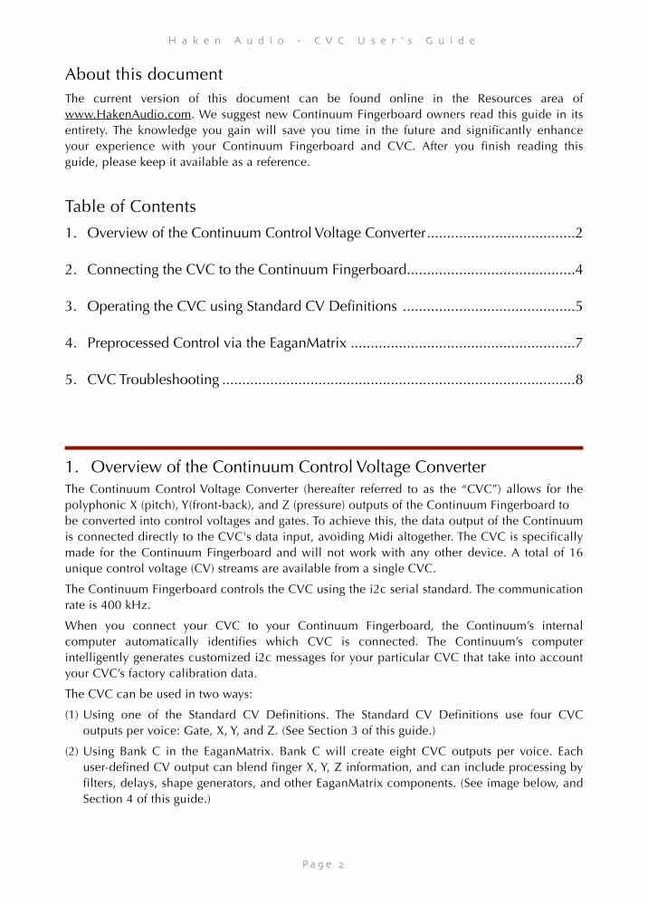
(2) Using Bank C in the EaganMatrix. Bank C will create eight CVC outputs per voice. Each user-defined CV output can blend finger X, Y, Z information, and can include processing by filters, delays, shape generators, and other EaganMatrix components. (See image below, and Section 4 of this guide.)
1. Overview of the Continuum Control Voltage Converter 2 .....................................
2. Connecting the CVC to the Continuum Fingerboard 4 ..........................................
3. Operating the CVC using Standard CV Definitions 5 ...........................................
4. Preprocessed Control via the EaganMatrix 7 ........................................................
5. CVC Troubleshooting 8........................................................................................
P a g e ���2
H a k e n A u d i o - C V C U s e r ’ s G u i d e
Continuum Editor. The current sound displayed above is using the EaganMatrix to control an external analog synthesizer through the CVC.
1.1.Front Panel
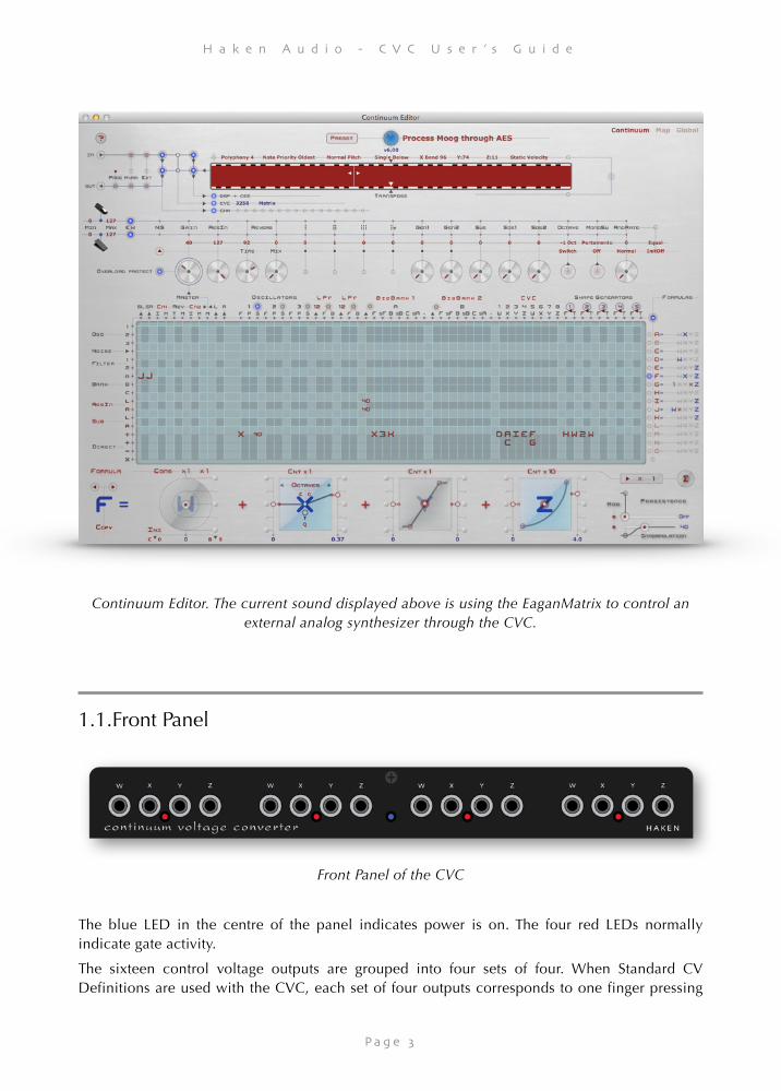
Front Panel of the CVC
The blue LED in the centre of the panel indicates power is on. The four red LEDs normally indicate gate activity.
The sixteen control voltage outputs are grouped into four sets of four. When Standard CV Definitions are used with the CVC, each set of four outputs corresponds to one finger pressing
P a g e ���3
H a k e n A u d i o - C V C U s e r ’ s G u i d e
on the surface; each finger has an associated Gate, X (pitch), Y (front-back), and Z (pressure). The Gate LED indicates when a finger is down and the gate is active. A variety of Standard CV Definitions are available, this is a popular one:
Gate: 0v inactive, 10v active X: 1v/octave, with middle C at 0v Y: 0v to 10v (with 5v in the middle) Z: 0v to 10v
Depending on your analog synthesizer, you will have particular preferences for voltage ranges of each output on your CVC. Your Continuum will allow you to switch between Standard CV Definitions at any time. Section 3.1 of this document lists the Standard CV Definitions available.
Take care to avoid shorting CVC outputs to ground for extended periods of time, as this could cause the CVC’s output drivers to overheat. If you have trouble with this, or if you would like optional output protection resistors installed in your CVC, please contact Haken Audio.
1.2.Back Panel
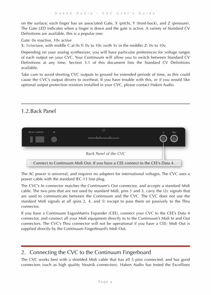
Back Panel of the CVC
The AC power is universal, and requires no adapters for international voltages. The CVC uses a power cable with the standard IEC-13 line plug.
The CVC’s In connector matches the Continuum’s Out connector, and accepts a standard Midi cable. The two pins that are not used by standard Midi, pins 1 and 3, carry the i2c signals that are used to communicate between the Continuum and the CVC. The CVC does not use the standard Midi signals at all (pins 2, 4, and 5) except to pass them on passively to the Thru connector.
If you have a Continuum EaganMatrix Expander (CEE), connect your CVC to the CEE’s Data 4 connector, and connect all your Midi equipment directly to to the Continuum’s Midi In and Out connectors. The CVC’s Thru connector will not be operational if you have a CEE; Midi Out is supplied directly by the Continuum Fingerboard’s Midi Out.
2. Connecting the CVC to the Continuum Fingerboard The CVC works best with a shielded Midi cable that has all 5 pins connected, and has good connectors (such as high quality Neutrik connectors). Haken Audio has tested the Excellines
P a g e ���4
Connect to Continuum Midi Out. If you have a CEE connect to the CEE’s Data 4.
H a k e n A u d i o - C V C U s e r ’ s G u i d e
Midi Cable, with a length of 10 feet or less. This cable is available in a variety of lengths from many on-line stores, including B & H.
Standard Connection: The CVC’s In port must be directly connected to your Continuum Fingerboard’s Midi Out. If you use the CVC in tandem with Midi synths or Midi connections to a computer, connect the CVC’s Midi Thru to the Midi In on your Midi synths or computer.
CEE Connection: If you are using a Continuum EaganMatrix Expander, connect your CVC’s In port to the CEE’s Data 4. If you use the CVC in tandem with Midi synths or Midi connections to a computer, connect your Continuum’s Midi Out/In to the Midi In/Out on your Midi synths or computer.
To test if your CVC is working: Make sure the Continuum is calibrated, make sure both the Continuum and the CVC are turned on and connected together, and configure Polyphony 4 on the Continuum (see the Continuum User Guide for instructions for configuring polyphony). Now play on the surface; you should see the Gate lights on the CVC front panel light up as you put down fingers; you should see it cycle through all four Gate lights as you continue playing.
3. Operating the CVC using Standard CV Definitions The Continuum Fingerboard will generate output for the CVC based on finger movements on the playing surface. At the same time, it will also generate standard Midi output and audio from the Continuum Fingerboard’s internal synthesizer. You can use the CVC to double voices played on other synths or on the internal synthesizer. Alternatively, you can configure so that the CVC plays (for example) lead lines and another synth or the internal synthesizer plays the other parts.
A single CVC can play up to four notes simultaneously. Normally you would configure your Continuum to polyphony of 4 or less when you use the CVC. If you configure polyphony greater than 4, a single CVC will assume polyphony 4.
If you configure Polyphony 1 on your Continuum, the leftmost four Gate, X, Y, Z outputs on the CVC will be used. If you configure Polyphony 2, then the left two sets of four outputs will be used. If you configure Polyphony 4, all four sets will be used.
The order in which the new notes from the playing surface are assigned to Midi channels can be LRU (assign the new note to the Least Recently Used voice) or LVN (assign to the Lowest Voice Number). The default is LRU. When the CVC is controlling a monophonic analog synthesizer, it can be useful to use LVN, so that the first finger to touch the surface always outputs on the leftmost Gate, X, Y, Z on the CVC, and the second finger to touch the surface (after the first is already touching) outputs on the second set of four outputs. In this way, the second finger can be used to consistently control some completely different parameters than the first. For details on configuring LVN and LRU, please see the Continuum User Guide Section 4.6.
The Continuum Fingerboard’s Mono and Split capabilities may be useful if you use the CVC together with standard Midi synths. If you have not done so already, please read about the Mono mode and Split configurations in the Continuum User’s Guide.
P a g e ���5
H a k e n A u d i o - C V C U s e r ’ s G u i d e
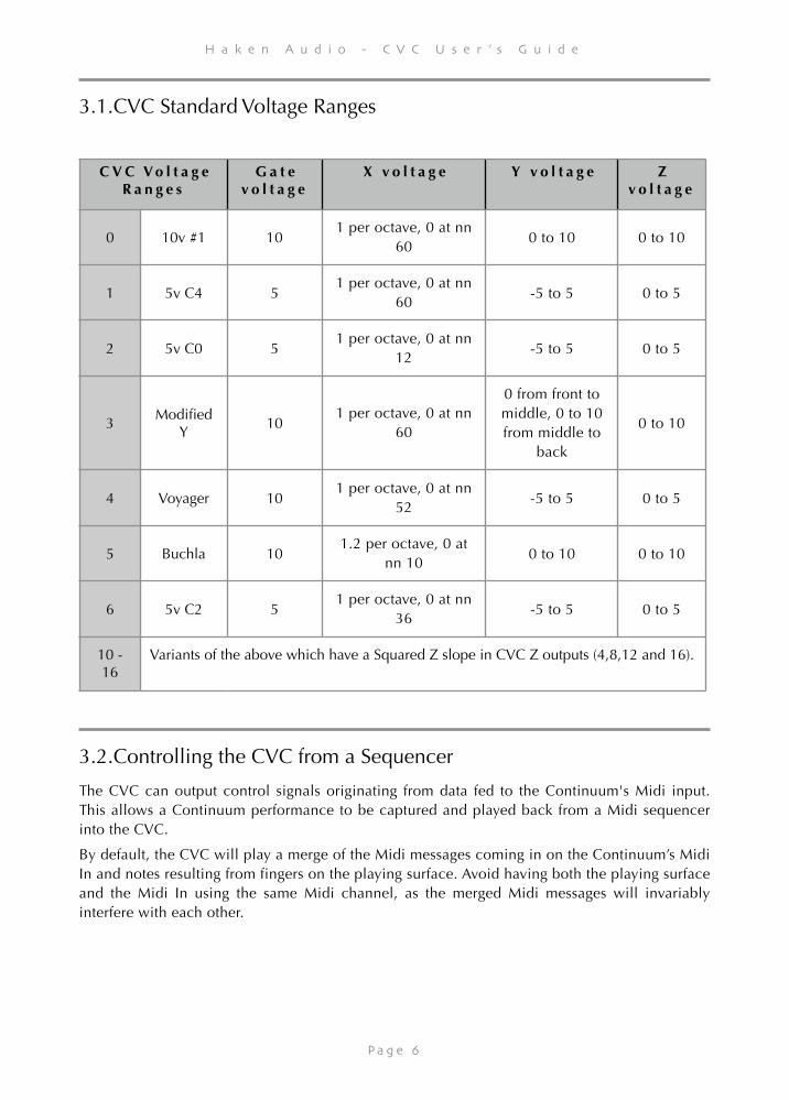
3.1.CVC Standard Voltage Ranges
3.2.Controlling the CVC from a Sequencer
The CVC can output control signals originating from data fed to the Continuum's Midi input. This allows a Continuum performance to be captured and played back from a Midi sequencer into the CVC.
By default, the CVC will play a merge of the Midi messages coming in on the Continuum’s Midi In and notes resulting from fingers on the playing surface. Avoid having both the playing surface and the Midi In using the same Midi channel, as the merged Midi messages will invariably interfere with each other.
C V C V o l t a g e R a n g e s
G a t e v o l t a g e
X v o l t a g e Y v o l t a g e Z v o l t a g e
0 10v #1 101 per octave, 0 at nn
600 to 10 0 to 10
1 5v C4 51 per octave, 0 at nn
60-5 to 5 0 to 5
2 5v C0 51 per octave, 0 at nn
12-5 to 5 0 to 5
3Modified
Y10
1 per octave, 0 at nn 60
0 from front to middle, 0 to 10 from middle to
back
0 to 10
4 Voyager 101 per octave, 0 at nn
52-5 to 5 0 to 5
5 Buchla 101.2 per octave, 0 at
nn 100 to 10 0 to 10
6 5v C2 51 per octave, 0 at nn
36-5 to 5 0 to 5
10 - 16
Variants of the above which have a Squared Z slope in CVC Z outputs (4,8,12 and 16).
P a g e ���6
H a k e n A u d i o - C V C U s e r ’ s G u i d e
3.3.Multi-tracking the CVC from a Sequencer
It is possible to control the CVC via multiple Midi performances. In doing these types of Midi overdubs, it is quite conceivable to overload the Midi capabilities of the external DAW sequencer, as the DAW may have problems merging multiple Continuum originated Midi streams into a single Midi output stream. Therefore it is usually advisable to do overdubbing in a more traditional way, by recording the output of the analog synthesizer as an audio track, and overdubbing with additional audio recordings into the DAW.
However, to do Midi overdubbing, below is the sequence of events to record and playback two monophonic CVC tracks:
(1) Configure the Continuum with “Polyphony 1” and Note Priority to “High 1”. Also disable Midi routing from Midi In to Midi Out.
(2) Play the first monophonic track; record it into your Midi sequencer as you play in on the CVC. This first track will be on Midi channel 1, and use the leftmost four outputs on the CVC.
(3) After you have finished playing the first track, configure the Continuum to Polyphony 2.
(4) Record the second track, as you play back the first track from your sequencer, and record the new notes into your sequencer. The new notes will be on Midi channel 2, and will come out on the second set of four outputs of your CVC. The previous track is on channel 1, and will come out on the leftmost set of outputs on your CVC.
(5) Now you can play back the two recorded tracks together through your CVC; but don’t touch the playing surface as you do so, because new notes will interfere with those two tracks (unless you set the Continuum’s polyphony to higher than 2).
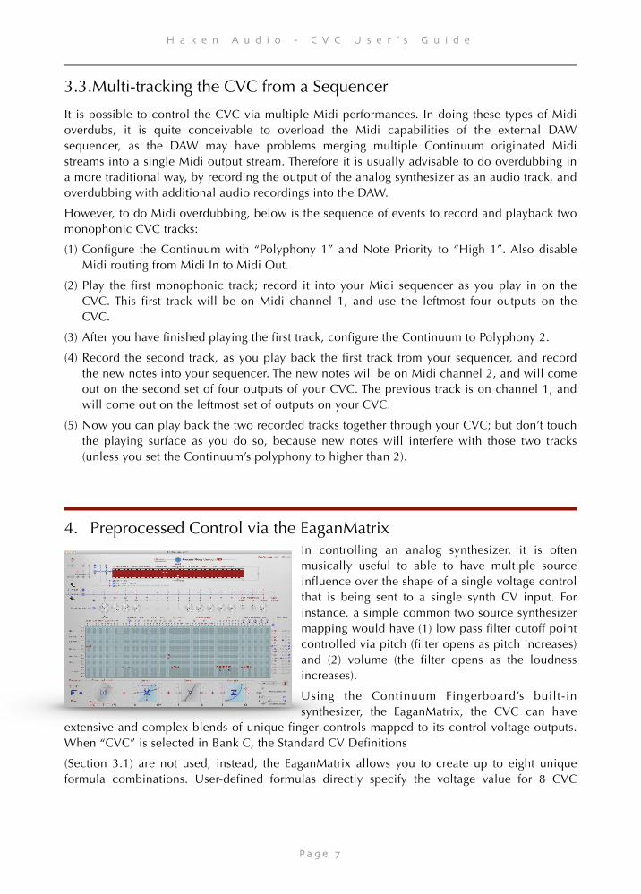
4. Preprocessed Control via the EaganMatrix In controlling an analog synthesizer, it is often musically useful to able to have multiple source influence over the shape of a single voltage control that is being sent to a single synth CV input. For instance, a simple common two source synthesizer mapping would have (1) low pass filter cutoff point controlled via pitch (filter opens as pitch increases) and (2) volume (the filter opens as the loudness increases).
Using the Continuum Fingerboard’s built-in synthesizer, the EaganMatrix, the CVC can have
extensive and complex blends of unique finger controls mapped to its control voltage outputs. When “CVC” is selected in Bank C, the Standard CV Definitions
(Section 3.1) are not used; instead, the EaganMatrix allows you to create up to eight unique formula combinations. User-defined formulas directly specify the voltage value for 8 CVC
P a g e ���7

H a k e n A u d i o - C V C U s e r ’ s G u i d e
outputs. The CVC will have 2 voice polyphony, with 8 user-defined control voltage outputs per voice. For details please read the EaganMatrix User’s guide.
5. CVC Troubleshooting
If the Blue Led on your CVC does not light up when turned on, please check the fuse. If your CVC plays no output at all, make sure your CVC is connected to your Continuum using a Midi cable with all 5 pins connected, and make sure your Continuum is properly calibrated. Try listening to the Continuum Fingerboard’s headphone output to verify that the Continuum is working.
If your CVC is connected to your Continuum Fingerboard it must be powered up, else your Continuum Fingerboard’s headphone output will not function and your Continuum Fingerboard’s LED will flash violet to indicate the problem. You must either power up your CVC, or disconnect it from your Continuum Fingerboard.
If you have an EaganMatrix Expander you must Connect your CVC to Data Port 4 on the Expander; it will not work if you connect your CVC directly to your continuum. You will see a
P a g e ���8
H a k e n A u d i o - C V C U s e r ’ s G u i d e
flashing violet LED if your CVC is connected but turned off, or if your EaganMatrix Expander is not communicating with your Continuum Fingerboard.
If your CVC does not use all the outputs – if only some, but not all, of the CVC gate outputs ever light up – the Continuum may have misidentified your CVC. Turn off your CVC (but leave your Continuum on), play some notes on the Continuum while the CVC is off, then turn the CVC back on and play some more notes. If your CVC’s address is correctly identified in the Continuum Editor, then the problem is something else; carefully check the configuration of your Continuum: Polyphony, Channel Assignment, Split, and Mono Interval affect which voices are used.
If you have intermittent problems with the CVC (notes drop out once in a while), you may be experiencing i2c communications errors on your Midi cable. Try a different high quality cable, and/or a shorter cable.
If any of these problems persist, please contact Haken Audio for further guidance.
.
P a g e ���9


