Page 1
8/21/2019 CX2600-220_Command_Reference_v7.6B_eng - Copy.pdf
http://slidepdf.com/reader/full/cx2600-220commandreferencev76beng-copypdf 1/758
CX2600/200Multi-Service Aggregation Switch
Command Reference
Notes
Read this manual in advance thoroughly to use this product correctly.
Keep the manual at hand for quick reference.MADE IN JAPAN
Page 2
8/21/2019 CX2600-220_Command_Reference_v7.6B_eng - Copy.pdf
http://slidepdf.com/reader/full/cx2600-220commandreferencev76beng-copypdf 2/758
Corresponding versions Version 07.06
Page 3
8/21/2019 CX2600-220_Command_Reference_v7.6B_eng - Copy.pdf
http://slidepdf.com/reader/full/cx2600-220commandreferencev76beng-copypdf 3/758
Revision History
Revision History
Rev. Published date Description
B May 2009 First edition published
Page 4
8/21/2019 CX2600-220_Command_Reference_v7.6B_eng - Copy.pdf
http://slidepdf.com/reader/full/cx2600-220commandreferencev76beng-copypdf 4/758
Revision History
(Blank page)
Page 5
8/21/2019 CX2600-220_Command_Reference_v7.6B_eng - Copy.pdf
http://slidepdf.com/reader/full/cx2600-220commandreferencev76beng-copypdf 5/758
Preface
Preface
i
Page 6
8/21/2019 CX2600-220_Command_Reference_v7.6B_eng - Copy.pdf
http://slidepdf.com/reader/full/cx2600-220commandreferencev76beng-copypdf 6/758
Preface
█ Before reading the command reference:
• Product name
The CX2600/200 comprise three models, CX2600/220, CX2600/210, and CX2600/202.
In this manual, the "CX2600/220" is sometimes used in equipment setting examples and so on.
In such a case, the contents are also applicable to the "CX2600/210" and "CX2600/202".
Special mention is provided for the sections specific to a particular model; however, the contents
are also applicable to the "CX2600/210" or "CX2600/202" accordingly, unless otherwise
indicated.
• This device has three types of modes to use commands.
General mode: Mode to use display commands and terminal local set commands that
do not involve configuration update (default)
Privileged mode: Mode to use all commands related to usual maintenance operation such
as display commands and configuration commands
Maintenance mode: Mode to use commands for file operations
GeneralMode
PrivilegedMode
MaintenanceMode
enable maintenance
disable end
Mode Transition and Command for Transition
• Marks located at the top of descriptions for each command indicate following meanings:
Privilege Indicates that this command can be used in privileged mode.
General Indicates that this command can be used in general mode.
(When both are displayed, the command can be used in both modes.)
Maintenance Indicates that this command can be used in maintenance mode.
(For details, see 24 “Maintenance Mode”.)
Save Indicates that the settings can be saved.
(Without an indication, the settings for the command cannot be saved.)
Synchronize Indicates that the settings automatically synchronize with the other
system when the device is operated in dual mode.
SBY execution Indicates that the command can be used by the standby system when
the device is operated in dual mode.
ii
Page 7
8/21/2019 CX2600-220_Command_Reference_v7.6B_eng - Copy.pdf
http://slidepdf.com/reader/full/cx2600-220commandreferencev76beng-copypdf 7/758
Preface
• Notation in “Input format” includes following meanings.
Parameters enclosed in brackets can be omitted.
When multiple parameters are enclosed in a pair of brackets, all the parameters enclosed can
be omitted.
Example)
[P1] : P1 can be omitted.
[P1 P2] : P1 and P2 can be omitted. Either one of P1 or P2 cannot be omitted.
[P1[P2]] : P1 and P2 can be omitted. P2 can be omitted without omitting P1, but P1
cannot be omitted without omitting P2.
Commands described with multiple input formats vary parameters to be specified according to
the settings.
In such a case, the key parameter is indicated as “Px (bold italic)” with an explanation.
Example)
P1 (aaa/bbb) P2 P3 : When aaa or bbb is specified by P1, specify P2 and P3.
P1 (ccc) P4 P5 : When ccc is specified by P1, specify P4 and P5.
• Notation in “Parameters” includes following meanings.
Braces indicate that one of the keywords delimited by vertical bars must be selected.
indicates that subsequent parameter to be specified varies according to parameters
previously specified.
In such a case, the affected parameter is indicated as “indent | (vertical bar)”. All the
parameters are affected as long as “indent |” continues.
* indicates a supplement for the parameter.
A keyword with _ (underline) indicates that the keyword needs to be input upon command
input.
iii
Page 8
8/21/2019 CX2600-220_Command_Reference_v7.6B_eng - Copy.pdf
http://slidepdf.com/reader/full/cx2600-220commandreferencev76beng-copypdf 8/758
Preface
iv
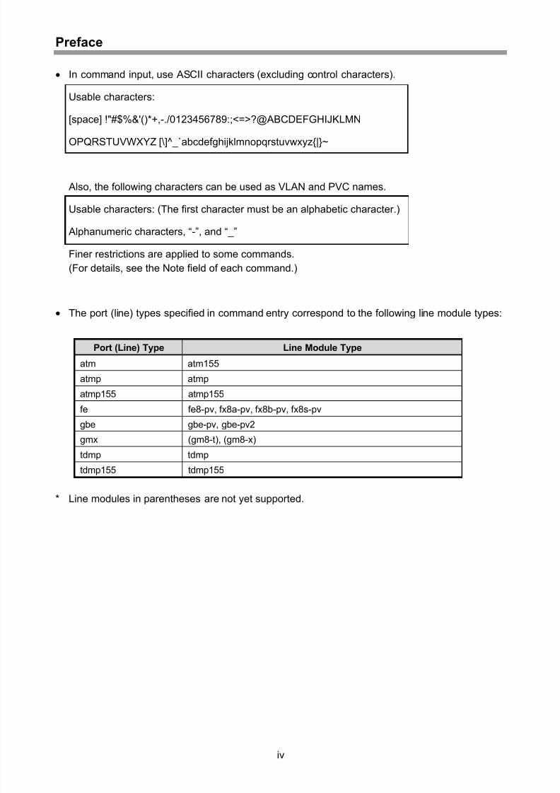
• In command input, use ASCII characters (excluding control characters).
Usable characters:
[space] !"#$%&'()*+,-./0123456789:;<=>?@ABCDEFGHIJKLMN
OPQRSTUVWXYZ [\]^_`abcdefghijklmnopqrstuvwxyz{|}~
Also, the following characters can be used as VLAN and PVC names.
Usable characters: (The first character must be an alphabetic character.)
Alphanumeric characters, “-”, and “_”
Finer restrictions are applied to some commands.
(For details, see the Note field of each command.)
• The port (line) types specified in command entry correspond to the following line module types:
Port (Line) Type Line Module Type
atm atm155
atmp atmp
atmp155 atmp155
fe fe8-pv, fx8a-pv, fx8b-pv, fx8s-pv
gbe gbe-pv, gbe-pv2
gmx (gm8-t), (gm8-x)
tdmp tdmp
tdmp155 tdmp155
* Line modules in parentheses are not yet supported.
Page 9
8/21/2019 CX2600-220_Command_Reference_v7.6B_eng - Copy.pdf
http://slidepdf.com/reader/full/cx2600-220commandreferencev76beng-copypdf 9/758
Preface
Cautions
(1) No part of this manual may be reproduced without prior written permission of the publisher.
(2) The contents of this manual may be revised without prior notice.
(3) All efforts have been made to ensure the accuracy of all information in this manual.
If you notice any part unclear, incorrect, or omitted in this manual, contact NEC.
(4) NEC assumes no liability for the result of operations despite (3).
(5) If you find any missing pages or pages out of order in this manual, please contact NEC for a
replacement.
v
Page 10
8/21/2019 CX2600-220_Command_Reference_v7.6B_eng - Copy.pdf
http://slidepdf.com/reader/full/cx2600-220commandreferencev76beng-copypdf 10/758
Preface
(Blank page)
vi
Page 11
8/21/2019 CX2600-220_Command_Reference_v7.6B_eng - Copy.pdf
http://slidepdf.com/reader/full/cx2600-220commandreferencev76beng-copypdf 11/758
Contents
Contents
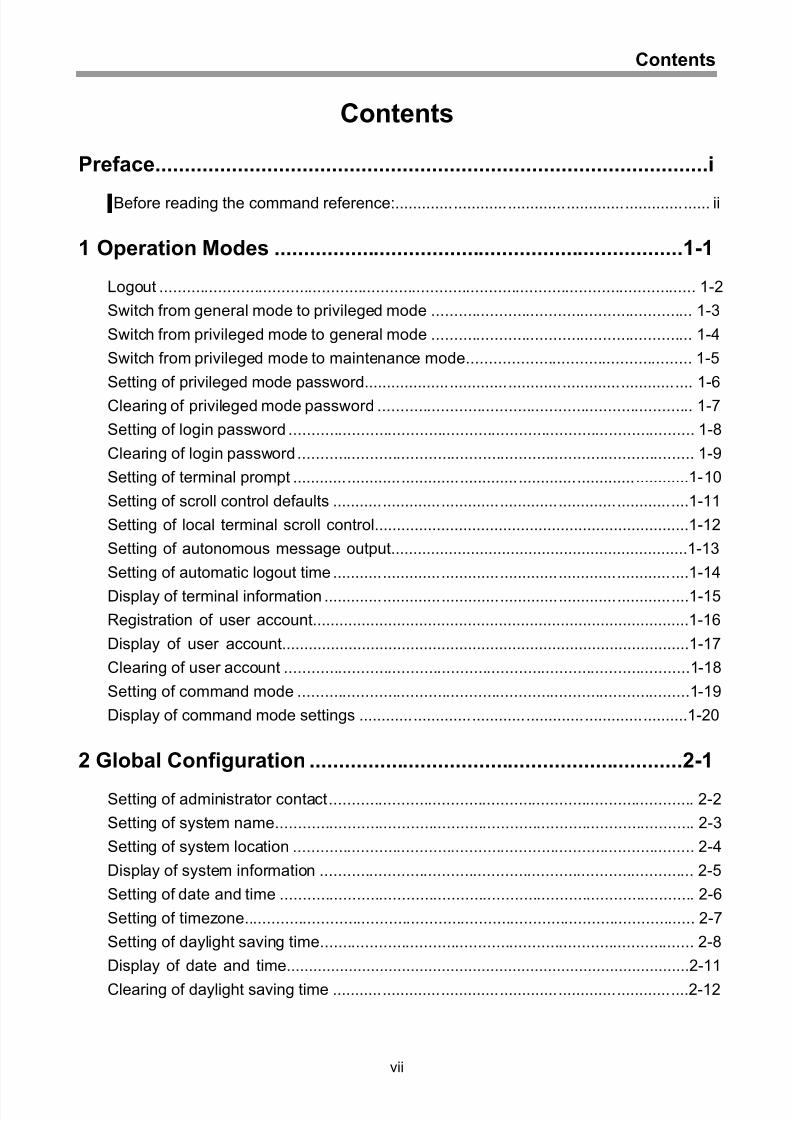
Preface..............................................................................................i
█ Before reading the command reference:...................................................................... ii
1 Operation Modes ......................................................................1-1
Logout ....................................................................................................................... 1-2
Switch from general mode to privileged mode .......................................................... 1-3
Switch from privileged mode to general mode .......................................................... 1-4
Switch from privileged mode to maintenance mode.................................................. 1-5
Setting of privileged mode password......................................................................... 1-6
Clearing of privileged mode password ...................................................................... 1-7
Setting of login password .......................................................................................... 1-8
Clearing of login password........................................................................................ 1-9
Setting of terminal prompt ........................................................................................1-10
Setting of scroll control defaults ...............................................................................1-11
Setting of local terminal scroll control.......................................................................1-12
Setting of autonomous message output...................................................................1-13
Setting of automatic logout time ...............................................................................1-14
Display of terminal information .................................................................................1-15
Registration of user account.....................................................................................1-16
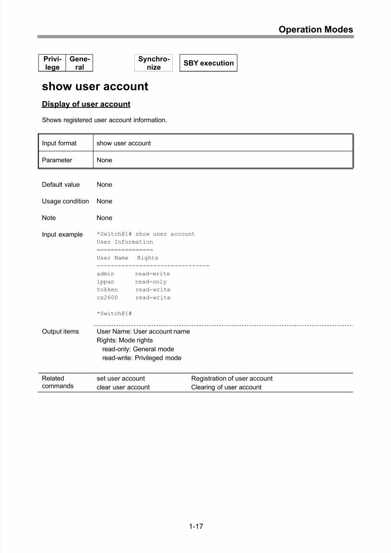
Display of user account............................................................................................1-17
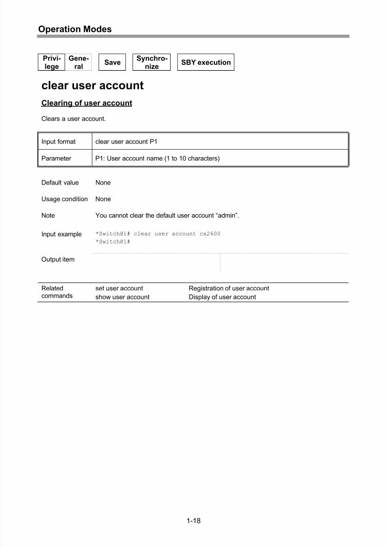
Clearing of user account ..........................................................................................1-18
Setting of command mode .......................................................................................1-19
Display of command mode settings .........................................................................1-20
2 Global Configuration ................................................................2-1
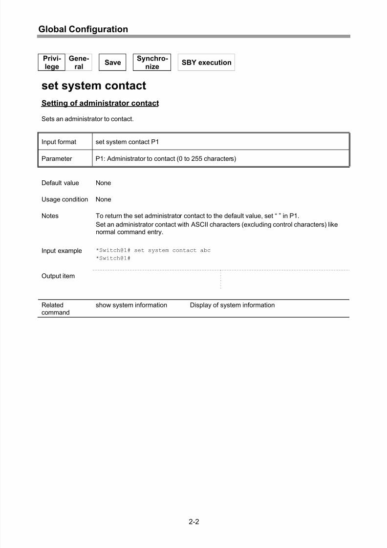
Setting of administrator contact................................................................................. 2-2
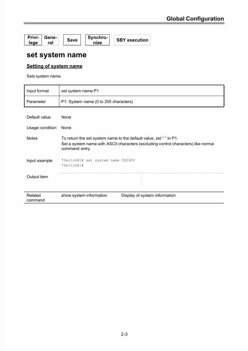
Setting of system name............................................................................................. 2-3
Setting of system location ......................................................................................... 2-4
Display of system information ................................................................................... 2-5
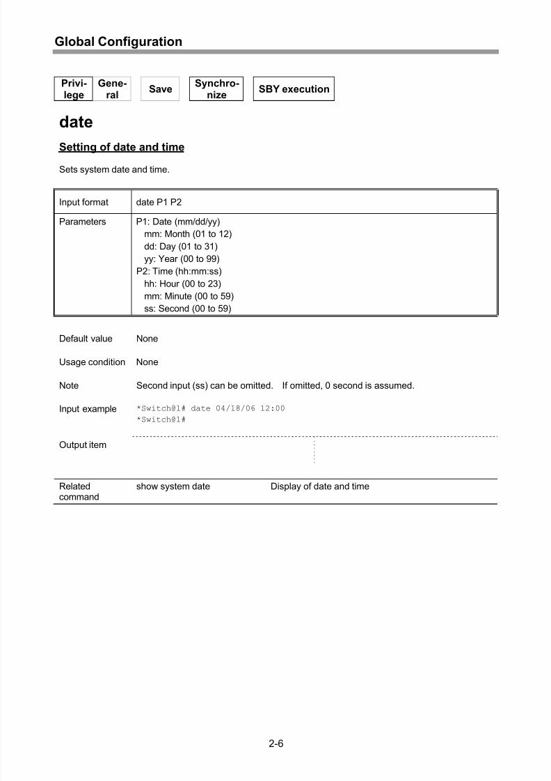
Setting of date and time ............................................................................................ 2-6
Setting of timezone.................................................................................................... 2-7
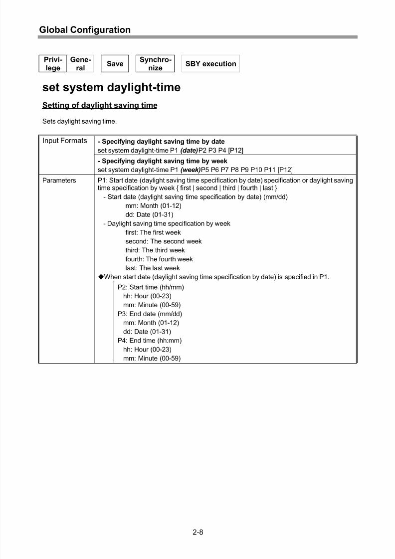
Setting of daylight saving time................................................................................... 2-8
Display of date and time...........................................................................................2-11
Clearing of daylight saving time ...............................................................................2-12
vii
Page 12
8/21/2019 CX2600-220_Command_Reference_v7.6B_eng - Copy.pdf
http://slidepdf.com/reader/full/cx2600-220commandreferencev76beng-copypdf 12/758
Contents
3 Administration Ports ................................................................3-1
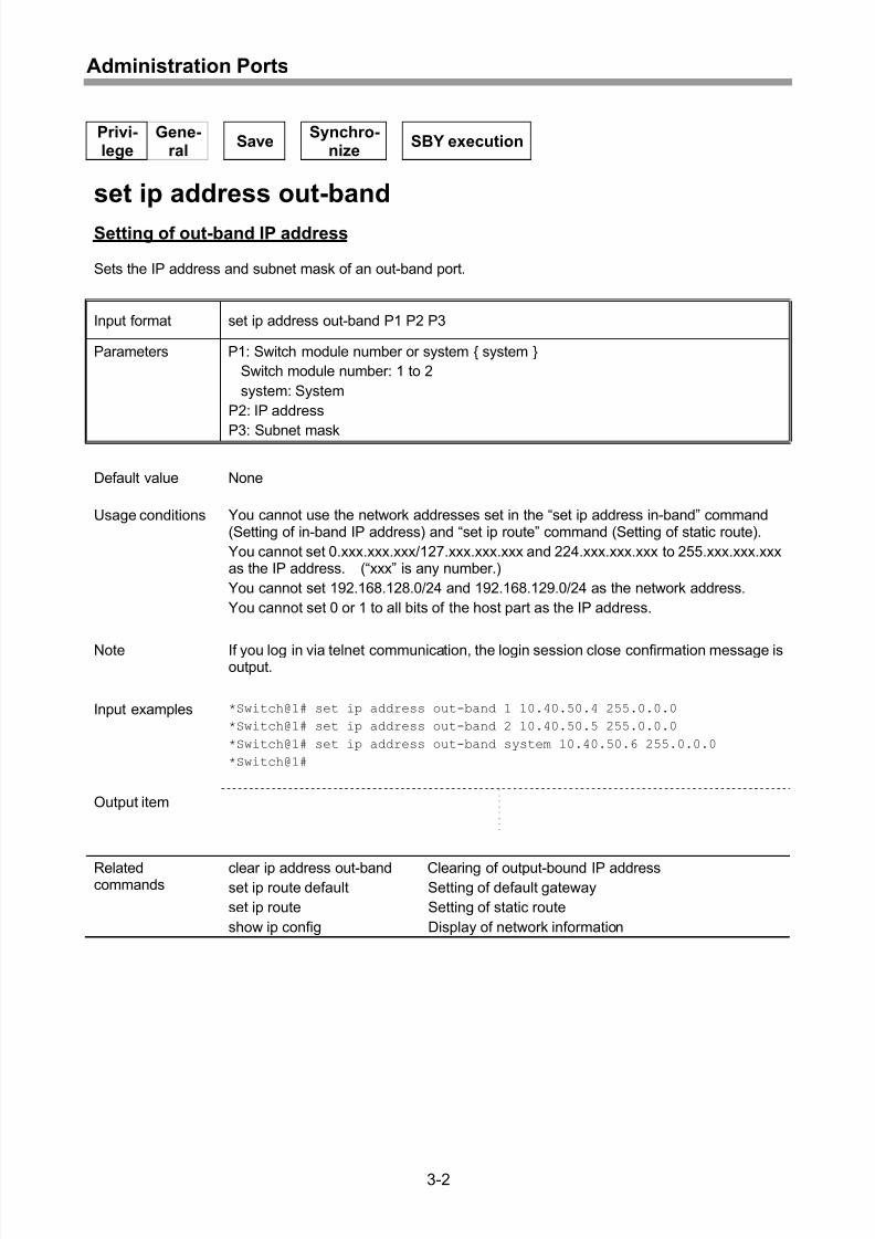
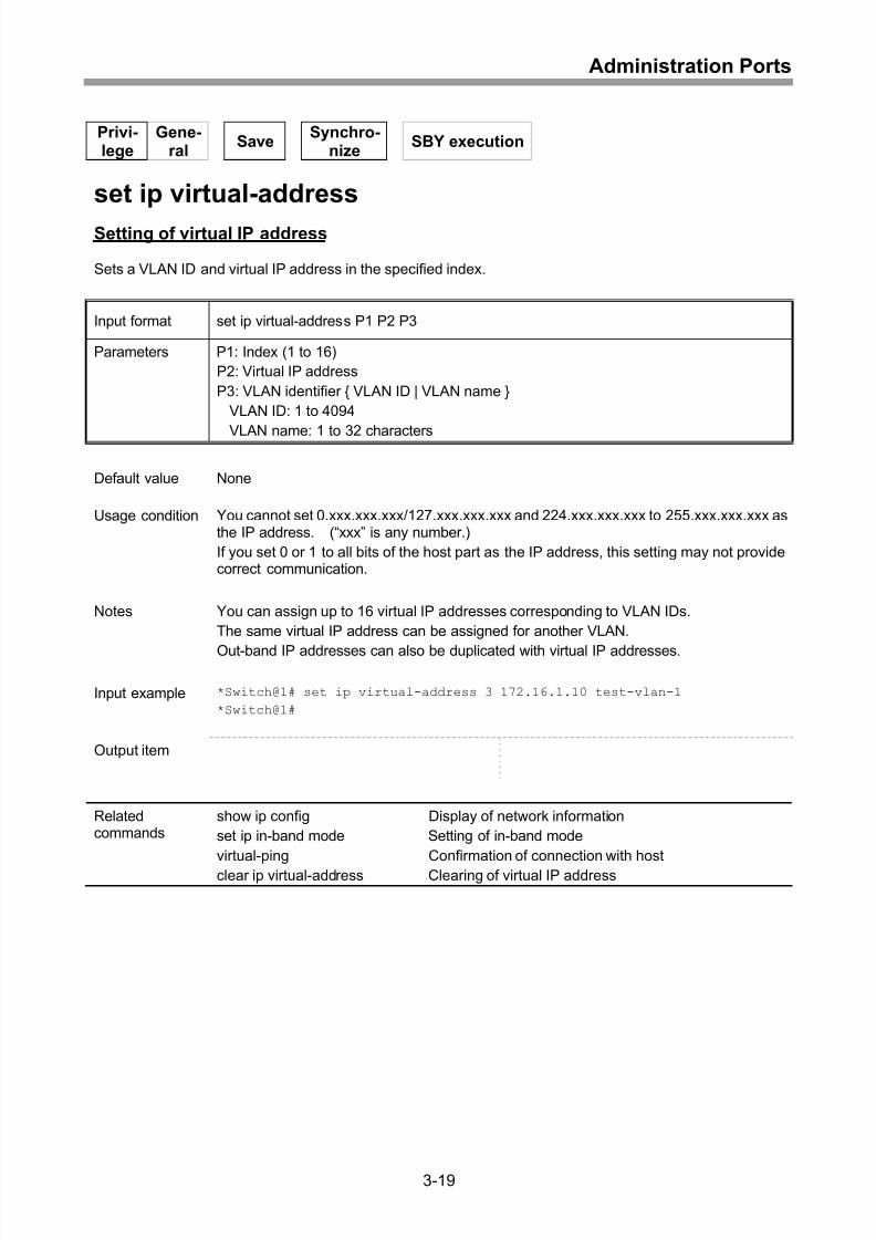
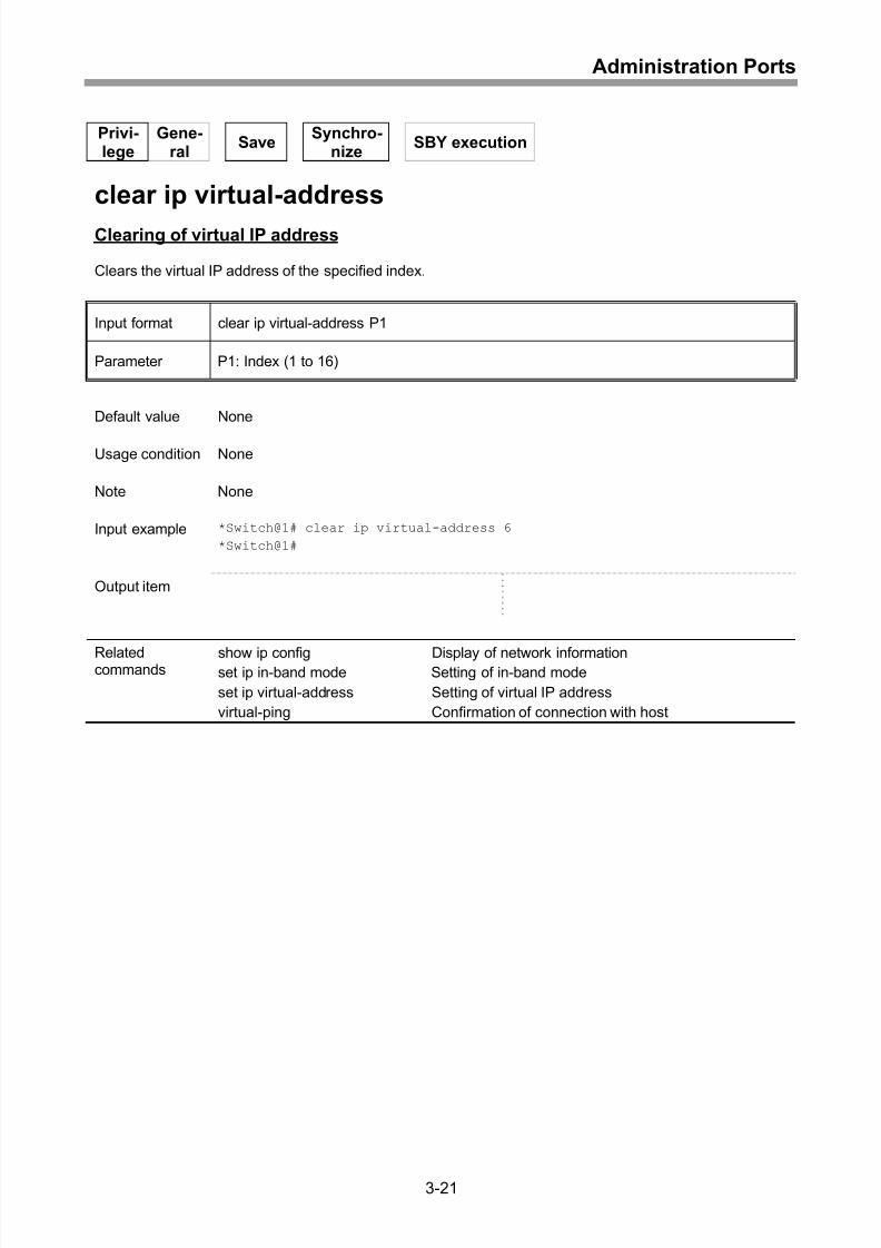
Setting of out-band IP address.................................................................................. 3-2
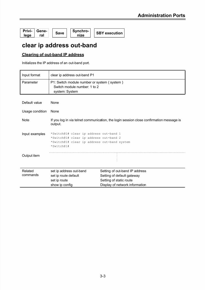
Clearing of out-band IP address................................................................................ 3-3
Setting of in-band IP address .................................................................................... 3-4
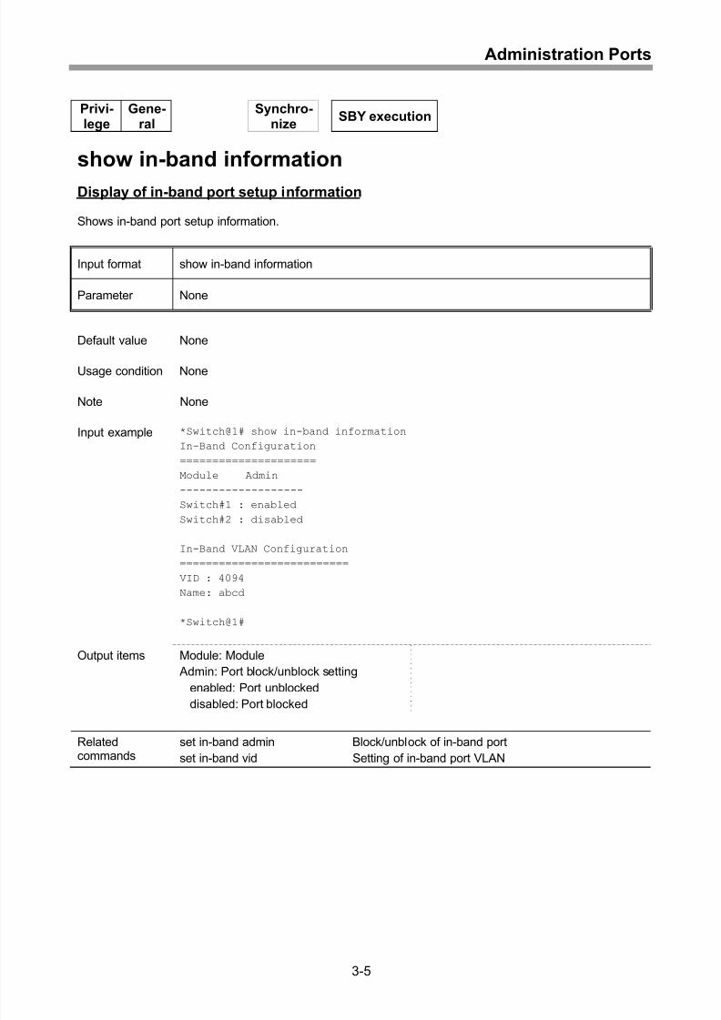
Display of in-band port setup information.................................................................. 3-5
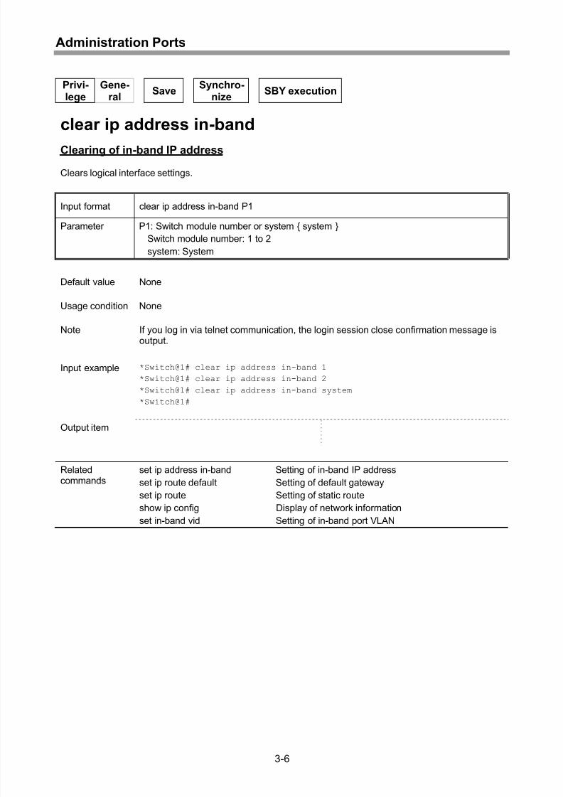
Clearing of in-band IP address.................................................................................. 3-6
Setting of default gateway......................................................................................... 3-7
Clearing of default gateway....................................................................................... 3-8
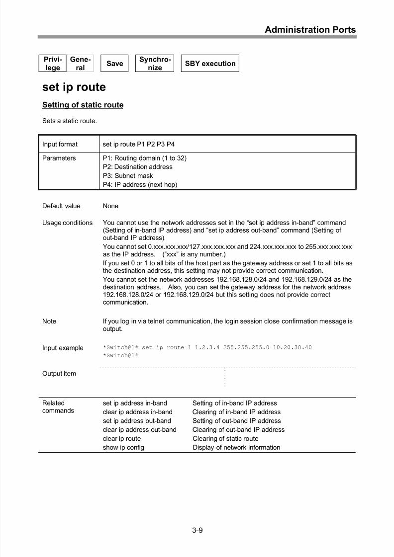
Setting of static route................................................................................................. 3-9
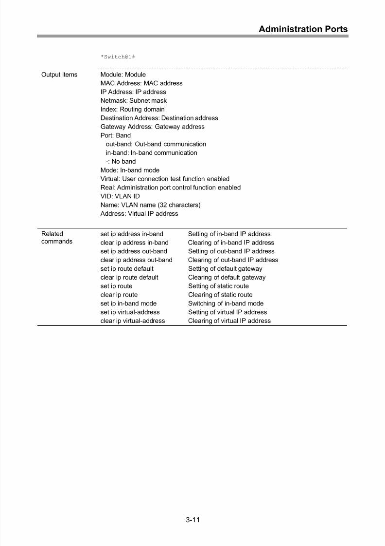
Display of network information .................................................................................3-10
Clearing of static route .............................................................................................3-12
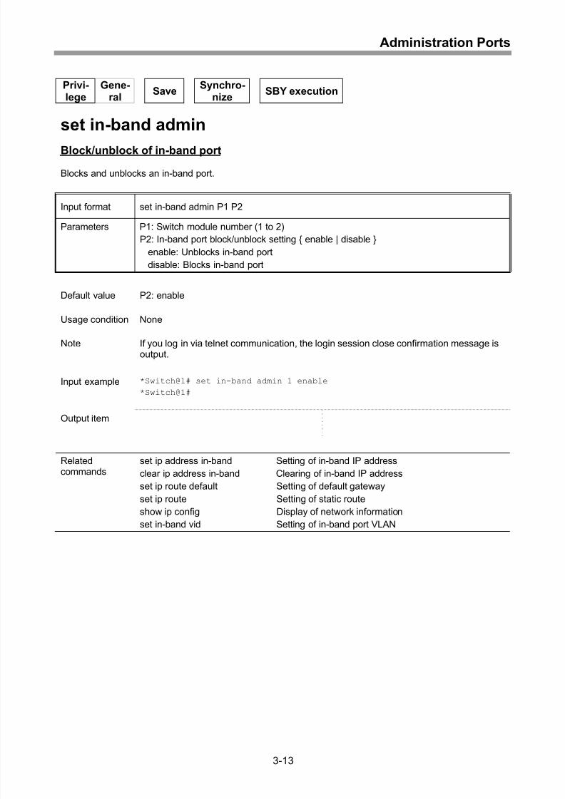
Block/unblock of in-band port ...................................................................................3-13
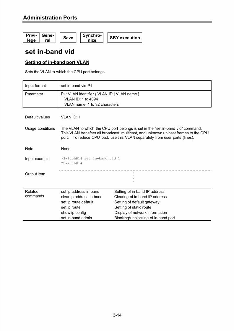
Setting of in-band port VLAN....................................................................................3-14
Setting of out-band port speed/communication direction..........................................3-15
Setting of out-band port flow control.........................................................................3-16
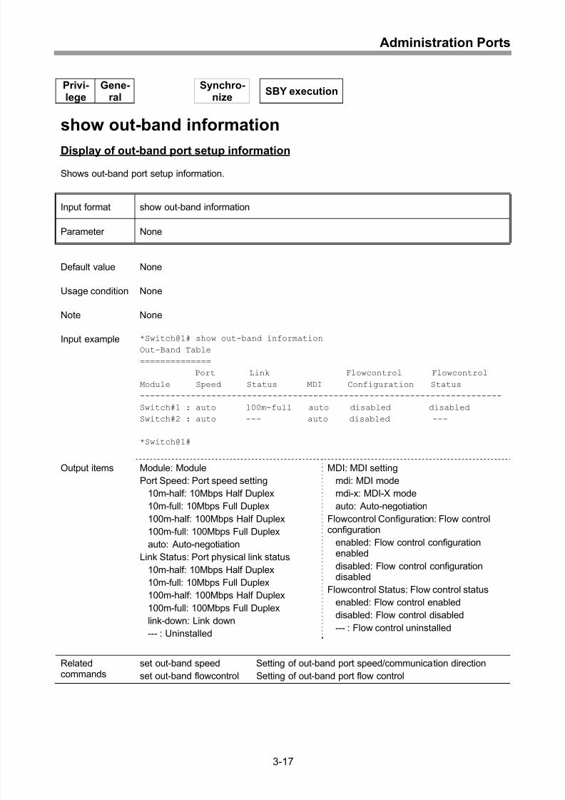
Display of out-band port setup information...............................................................3-17
Checking of connection............................................................................................3-18
Setting of virtual IP address .....................................................................................3-19
Confirmation of connection with host........................................................................3-20
Clearing of virtual IP address ...................................................................................3-21
Setting of in-band mode ...........................................................................................3-22
4 Ports...........................................................................................4-1
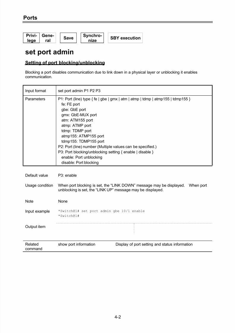
Setting of port blocking/unblocking............................................................................ 4-2
Setting of port speed and MDI/MDI-X........................................................................ 4-3
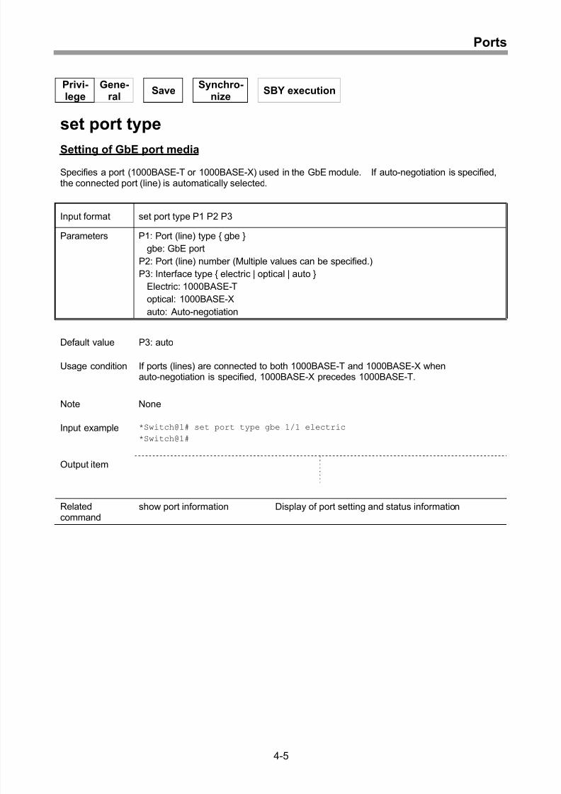
Setting of GbE port media......................................................................................... 4-5
Setting of flow control ................................................................................................ 4-6
Setting of port link protection time ............................................................................. 4-7
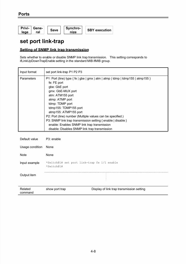
Setting of SNMP link trap transmission ..................................................................... 4-8
Setting of ATM transmission path clock .................................................................... 4-9
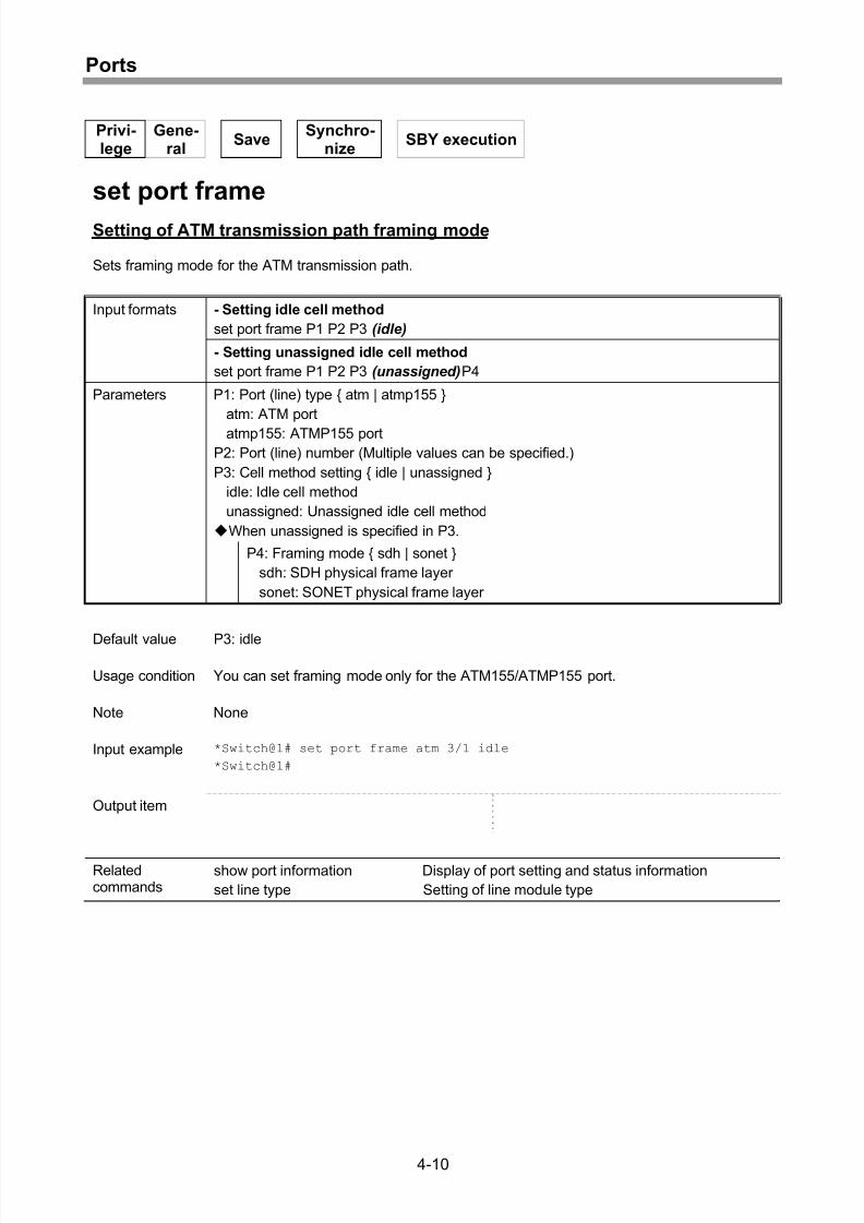
Setting of ATM transmission path framing mode......................................................4-10
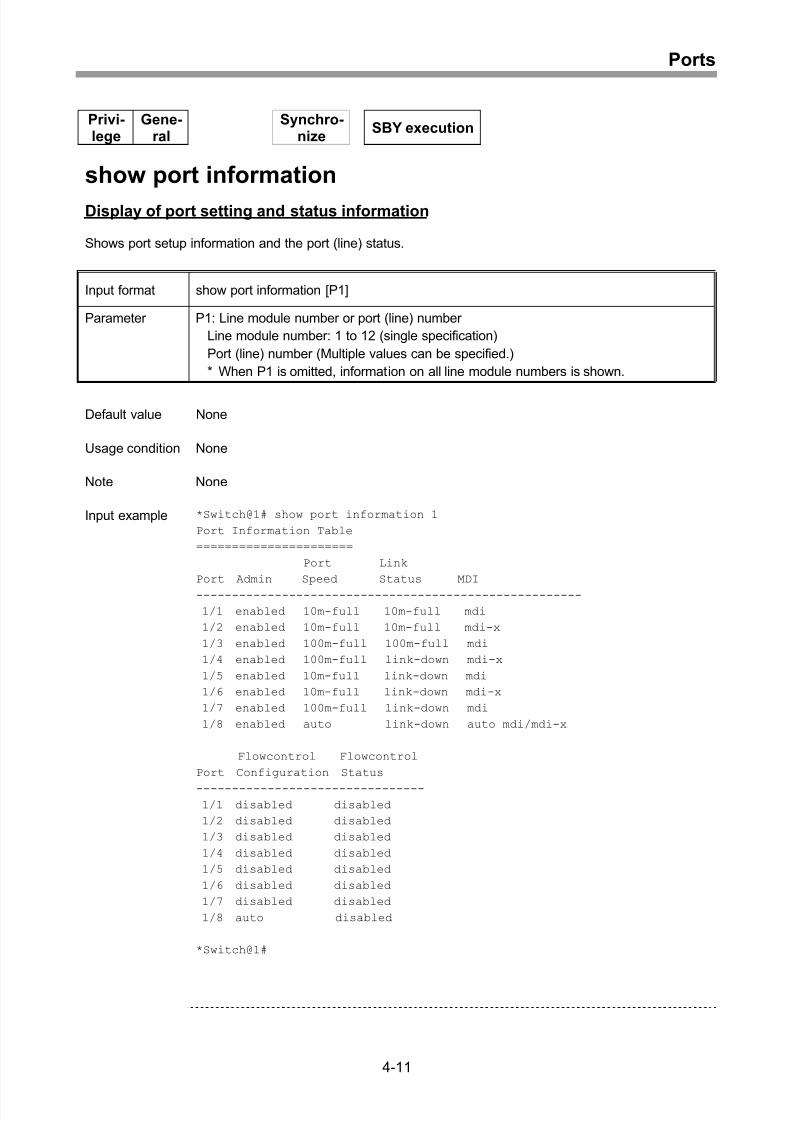
Display of port setting and status information...........................................................4-11
Display of link trap transmission setting ...................................................................4-16
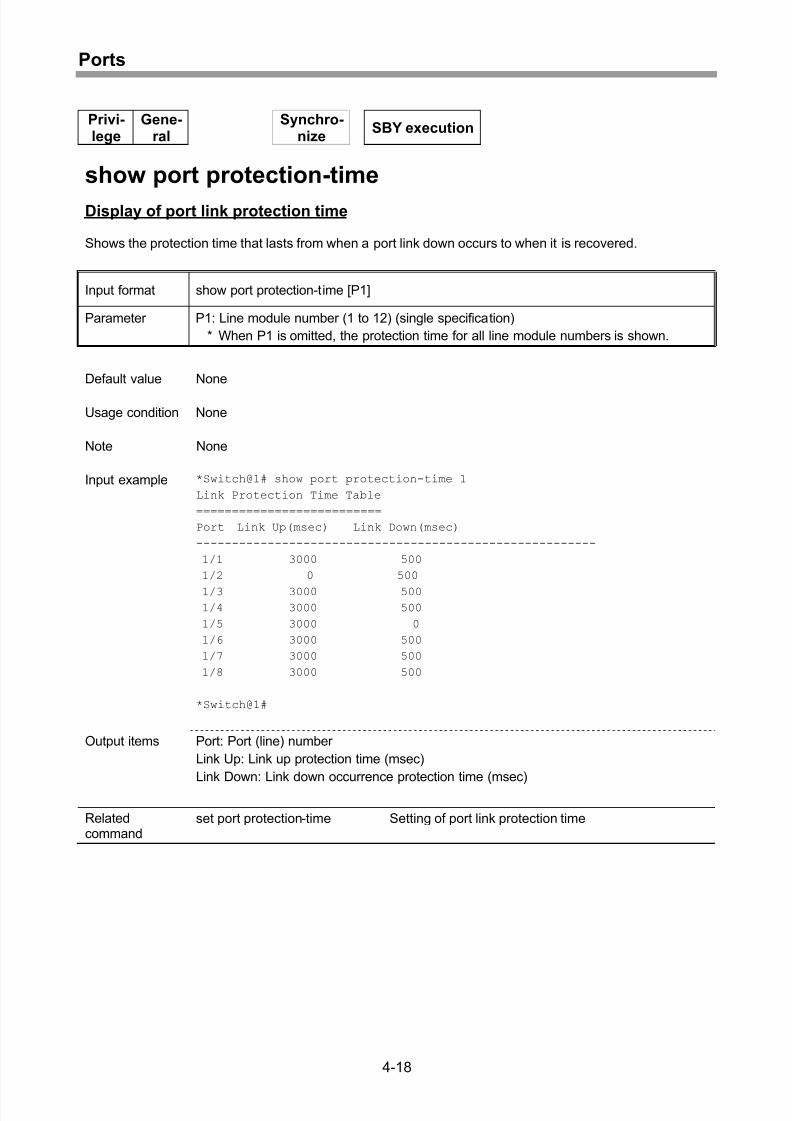
Display of port link protection time ...........................................................................4-18
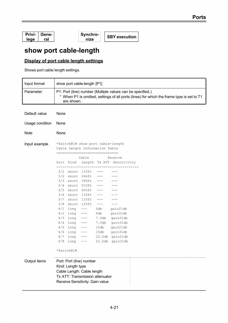
Setting of port cable length.......................................................................................4-19
Display of port cable length settings.........................................................................4-21
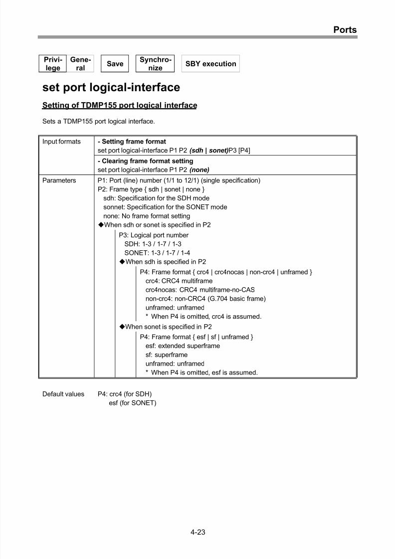
Setting of TDMP155 port logical interface................................................................4-23
viii
Page 13
8/21/2019 CX2600-220_Command_Reference_v7.6B_eng - Copy.pdf
http://slidepdf.com/reader/full/cx2600-220commandreferencev76beng-copypdf 13/758
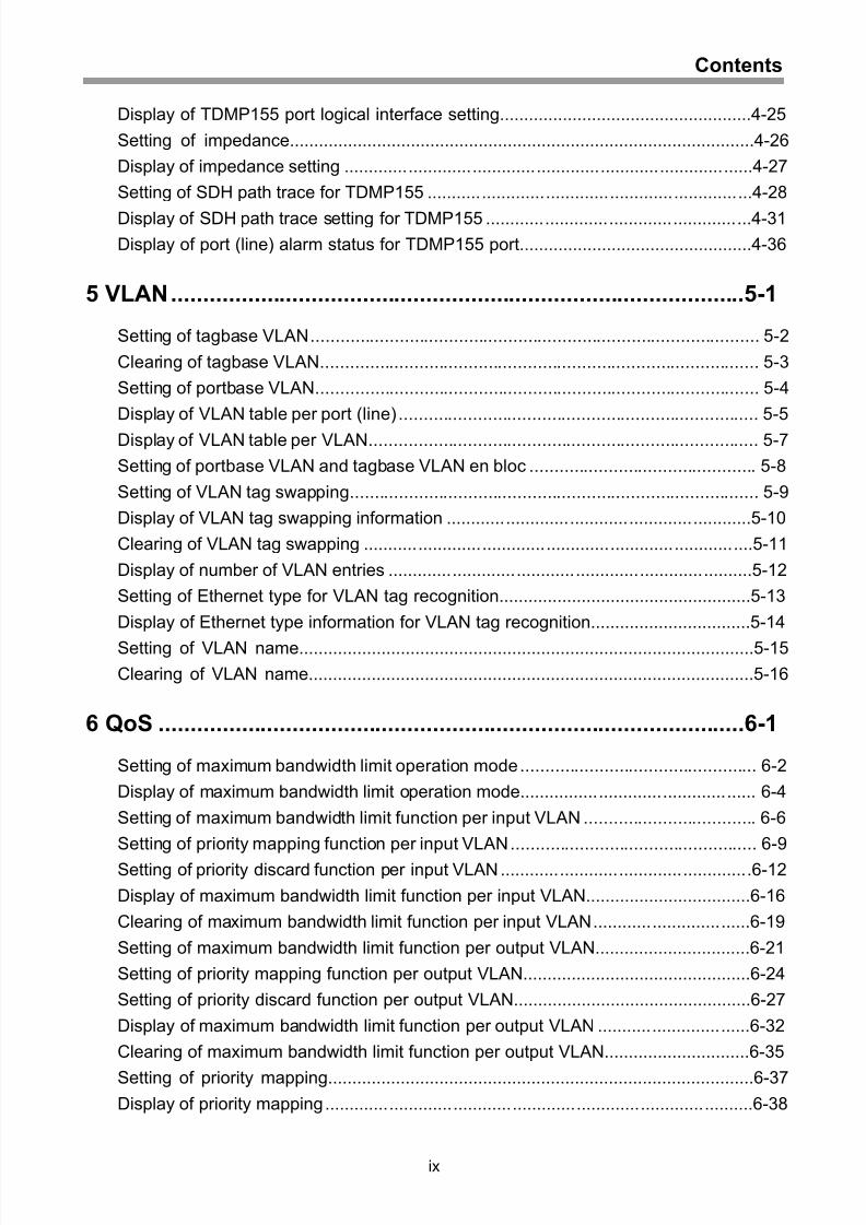
Contents
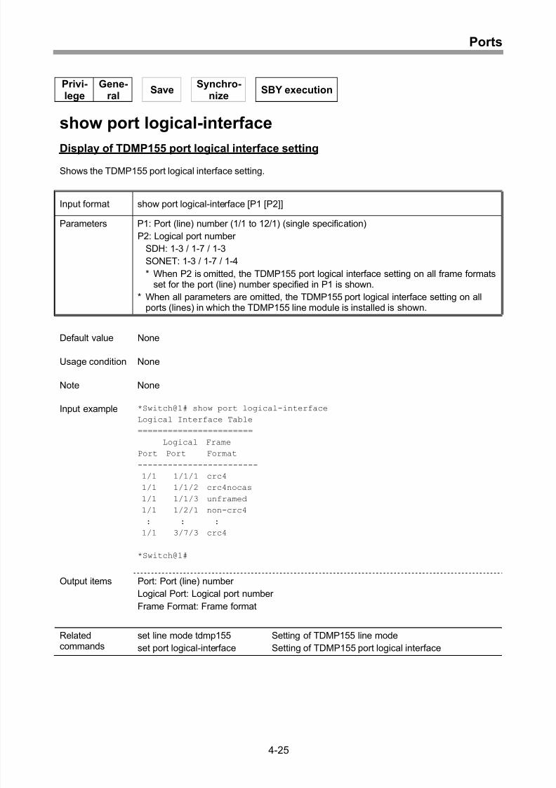
Display of TDMP155 port logical interface setting....................................................4-25
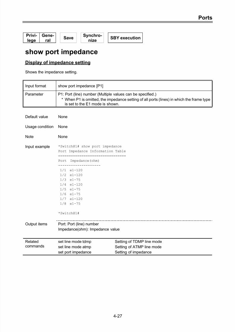
Setting of impedance................................................................................................4-26
Display of impedance setting ...................................................................................4-27
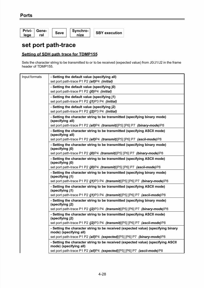
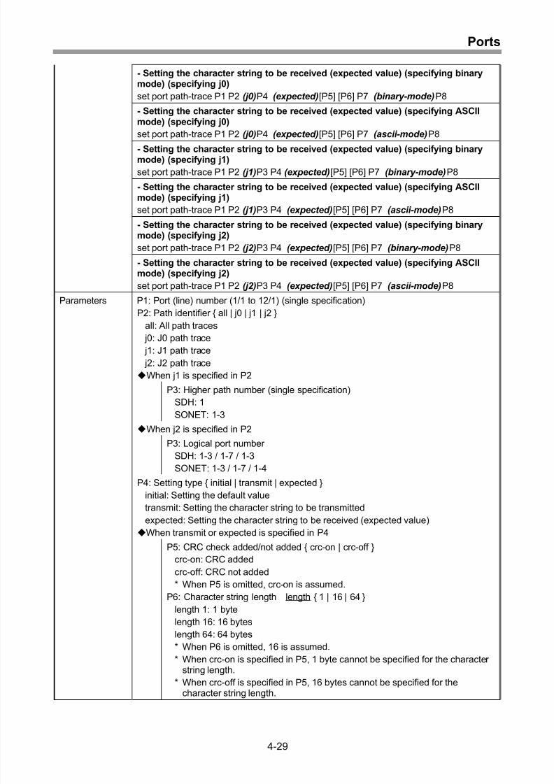
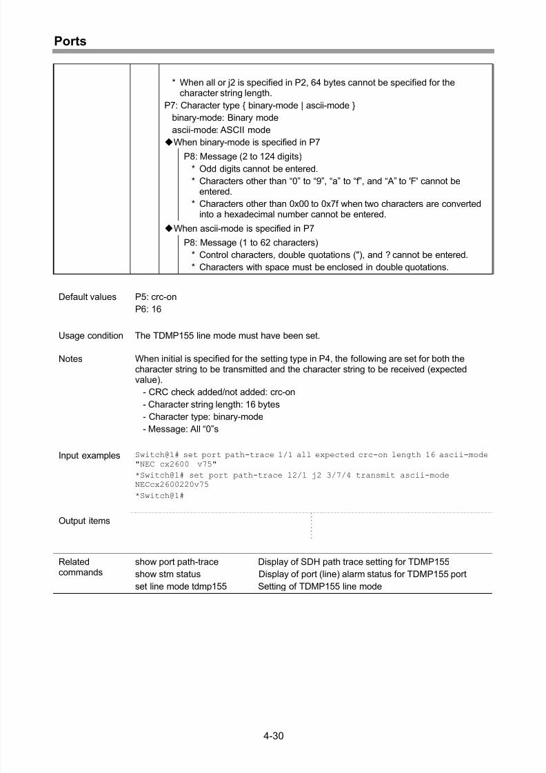
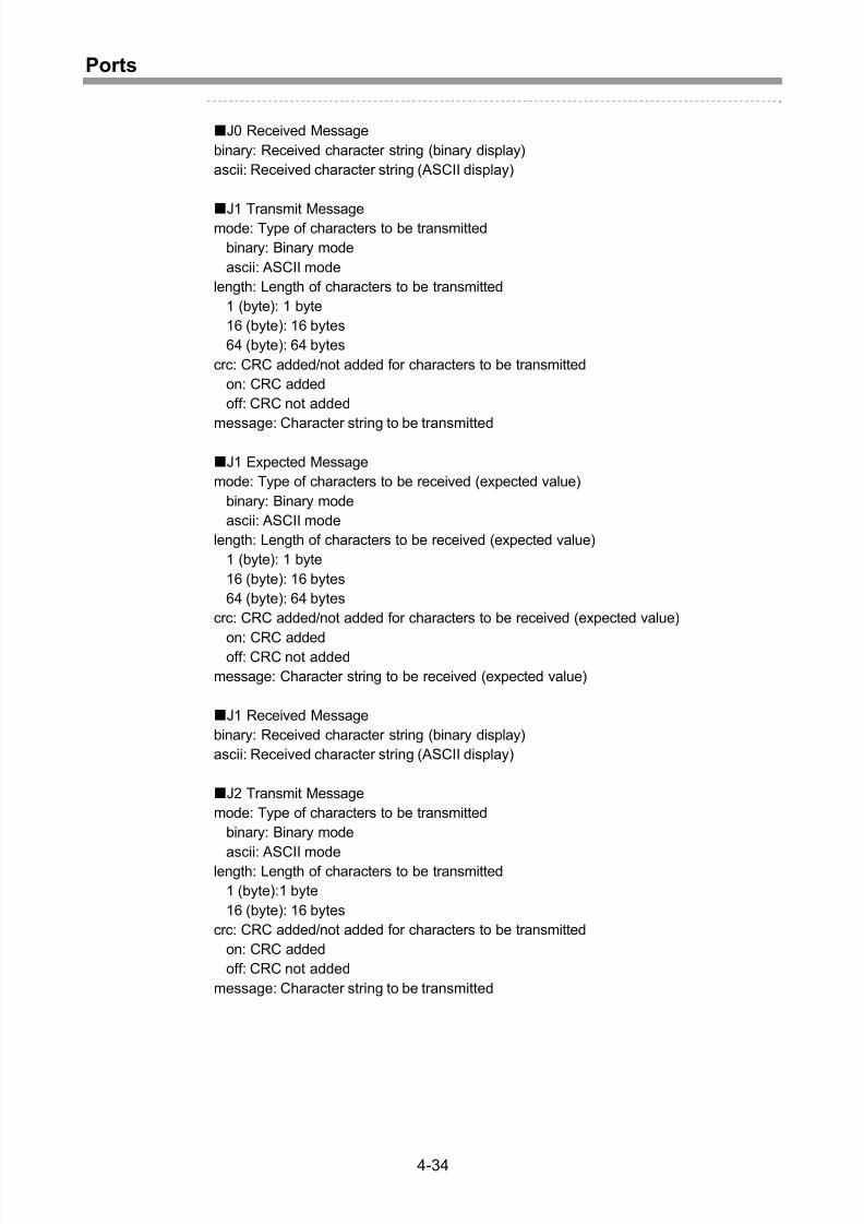
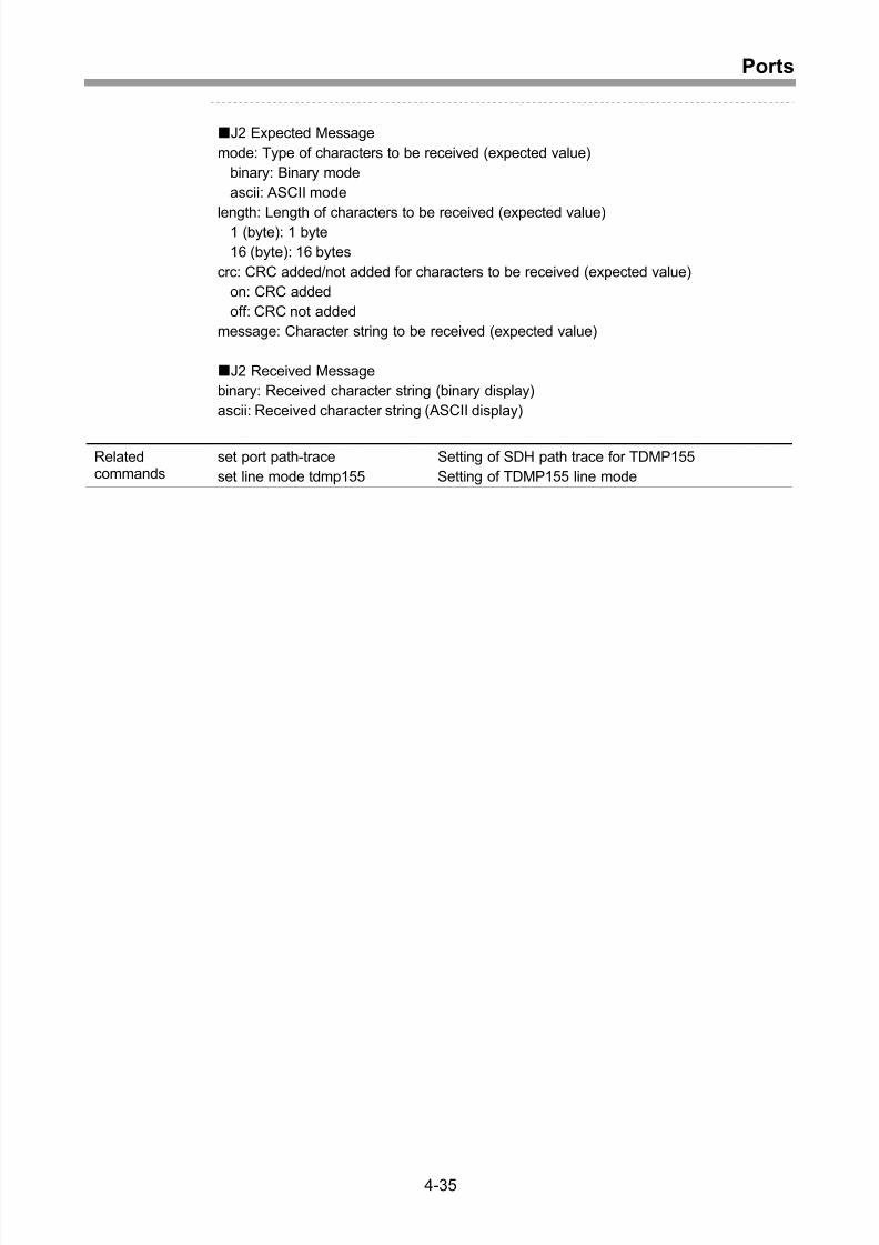
Setting of SDH path trace for TDMP155 ..................................................................4-28
Display of SDH path trace setting for TDMP155 ......................................................4-31
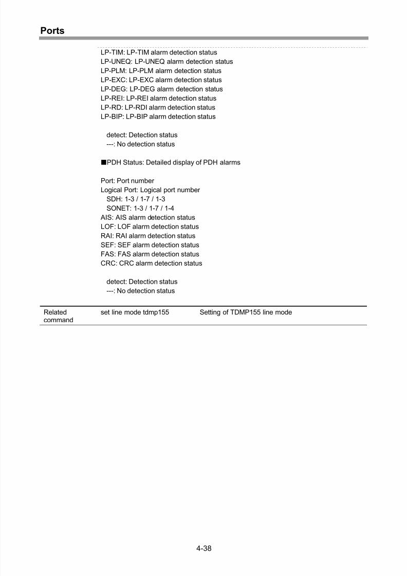
Display of port (line) alarm status for TDMP155 port................................................4-36
5 VLAN..........................................................................................5-1
Setting of tagbase VLAN........................................................................................... 5-2
Clearing of tagbase VLAN......................................................................................... 5-3
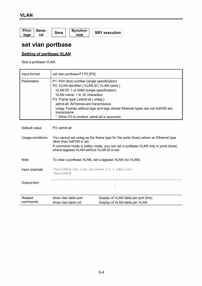
Setting of portbase VLAN.......................................................................................... 5-4
Display of VLAN table per port (line) ......................................................................... 5-5
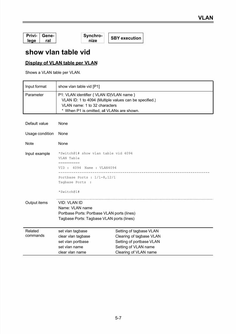
Display of VLAN table per VLAN............................................................................... 5-7
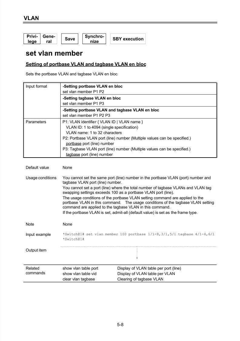
Setting of portbase VLAN and tagbase VLAN en bloc .............................................. 5-8
Setting of VLAN tag swapping................................................................................... 5-9
Display of VLAN tag swapping information ..............................................................5-10
Clearing of VLAN tag swapping ...............................................................................5-11
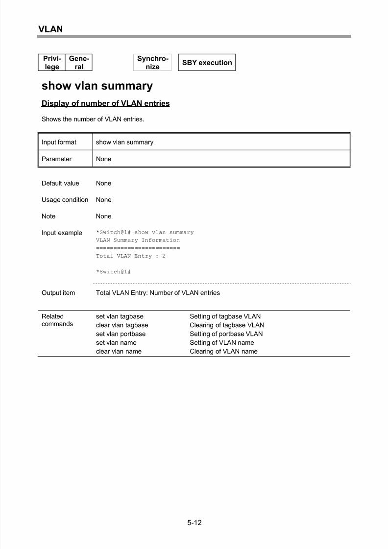
Display of number of VLAN entries ..........................................................................5-12
Setting of Ethernet type for VLAN tag recognition....................................................5-13
Display of Ethernet type information for VLAN tag recognition.................................5-14
Setting of VLAN name..............................................................................................5-15
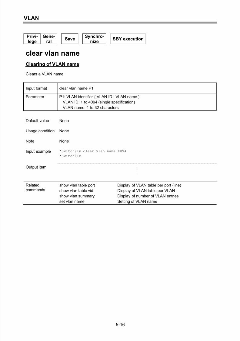
Clearing of VLAN name............................................................................................5-16
6 QoS ............................................................................................6-1
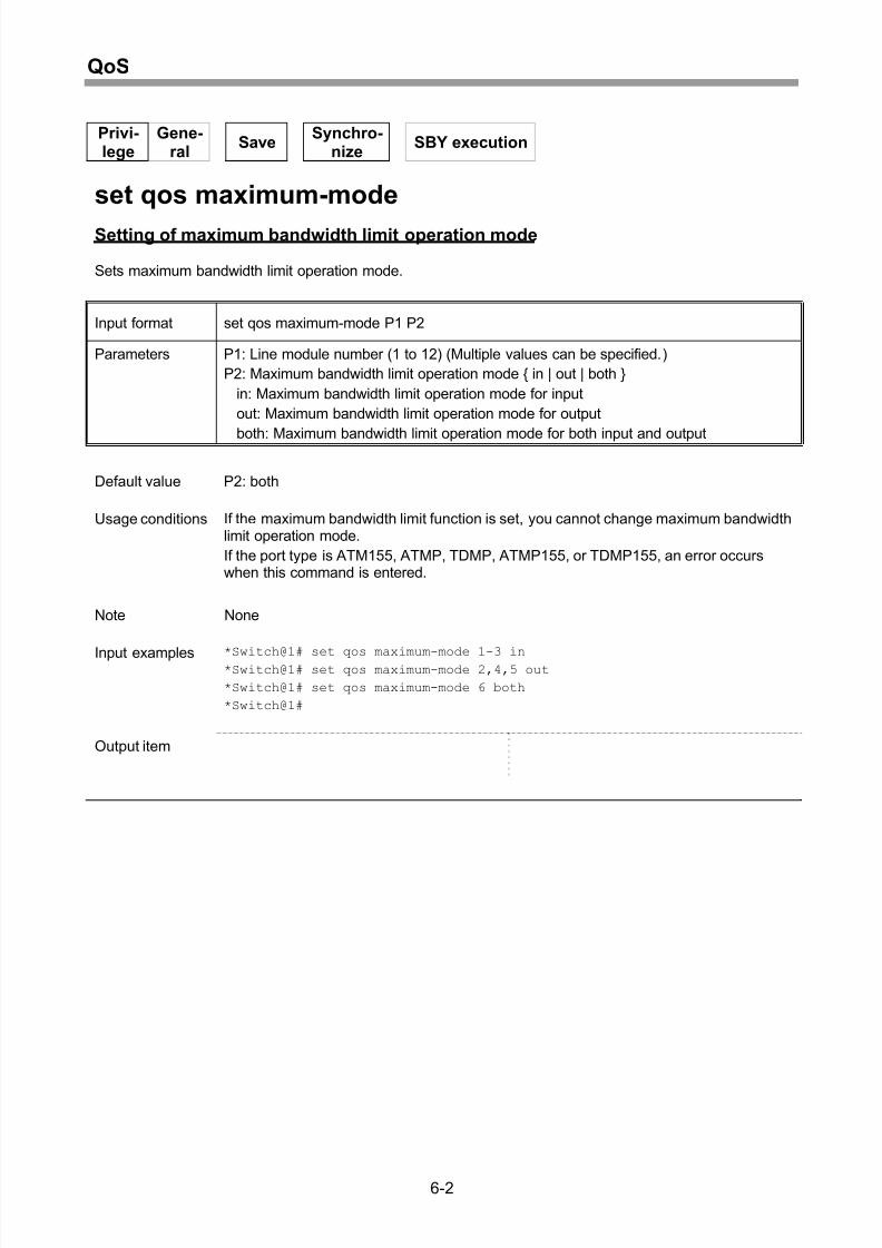
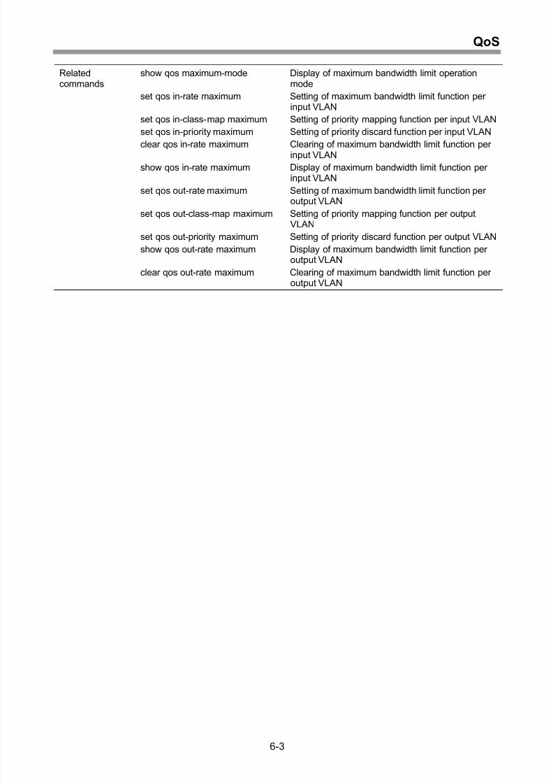
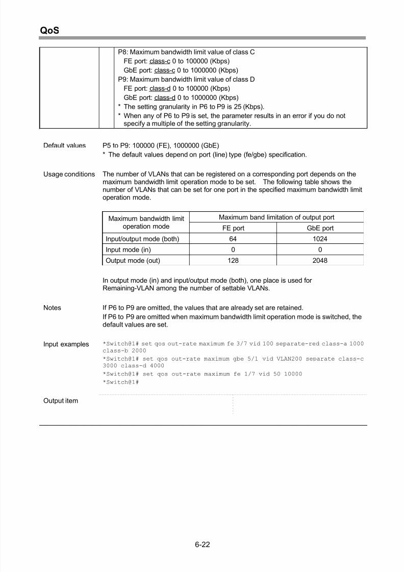
Setting of maximum bandwidth limit operation mode................................................ 6-2
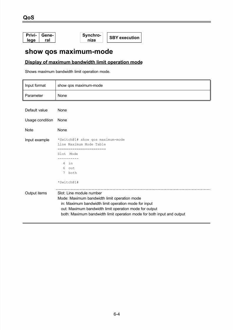
Display of maximum bandwidth limit operation mode................................................ 6-4
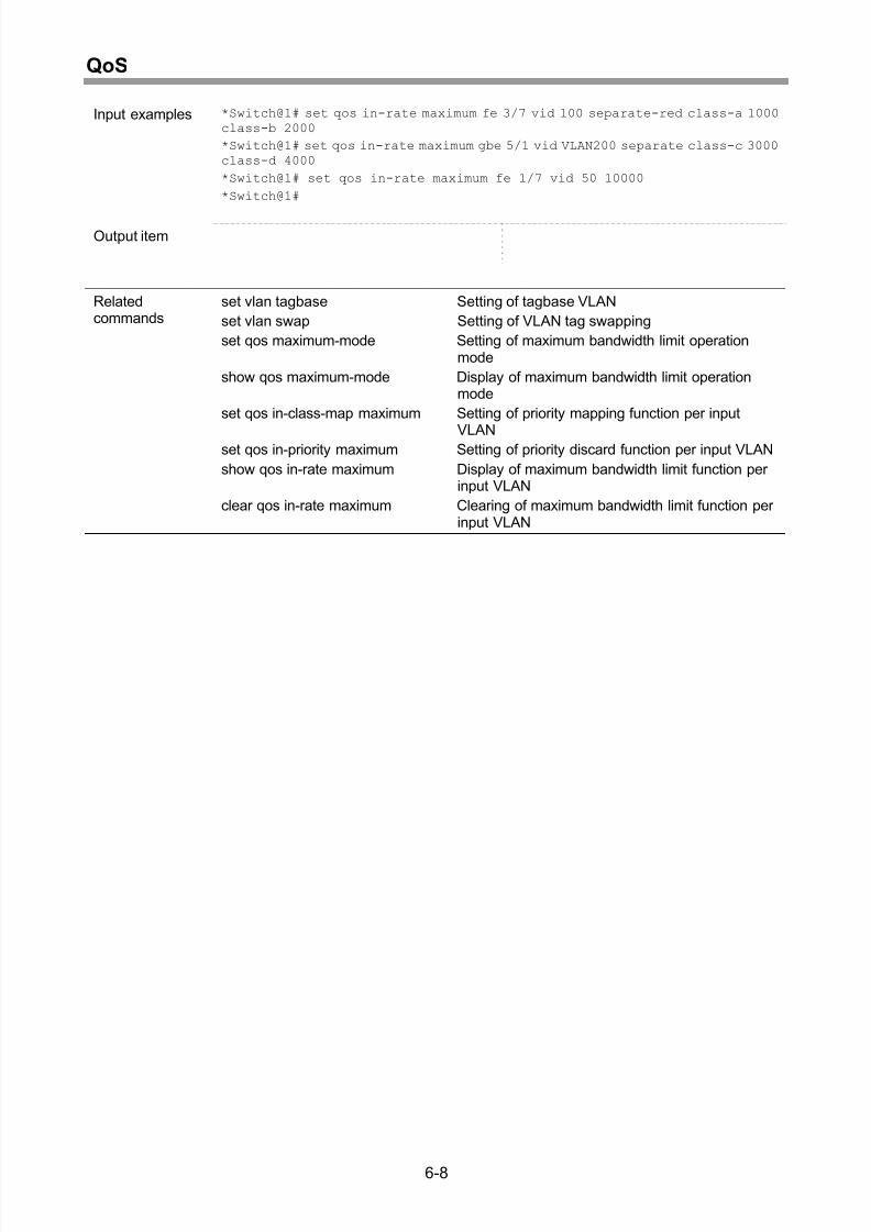
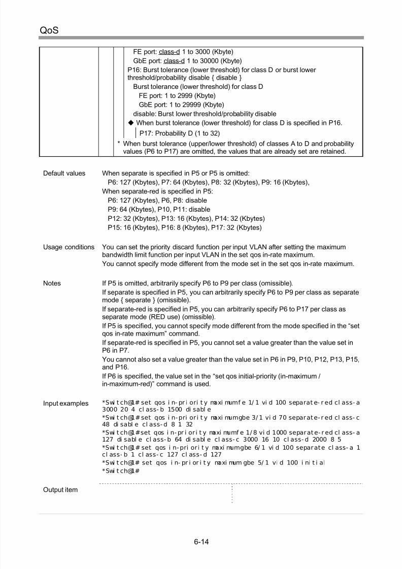
Setting of maximum bandwidth limit function per input VLAN ................................... 6-6
Setting of priority mapping function per input VLAN.................................................. 6-9
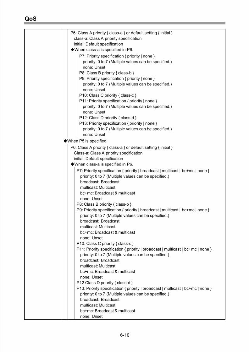
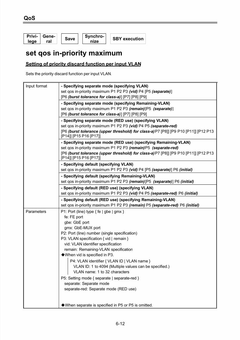
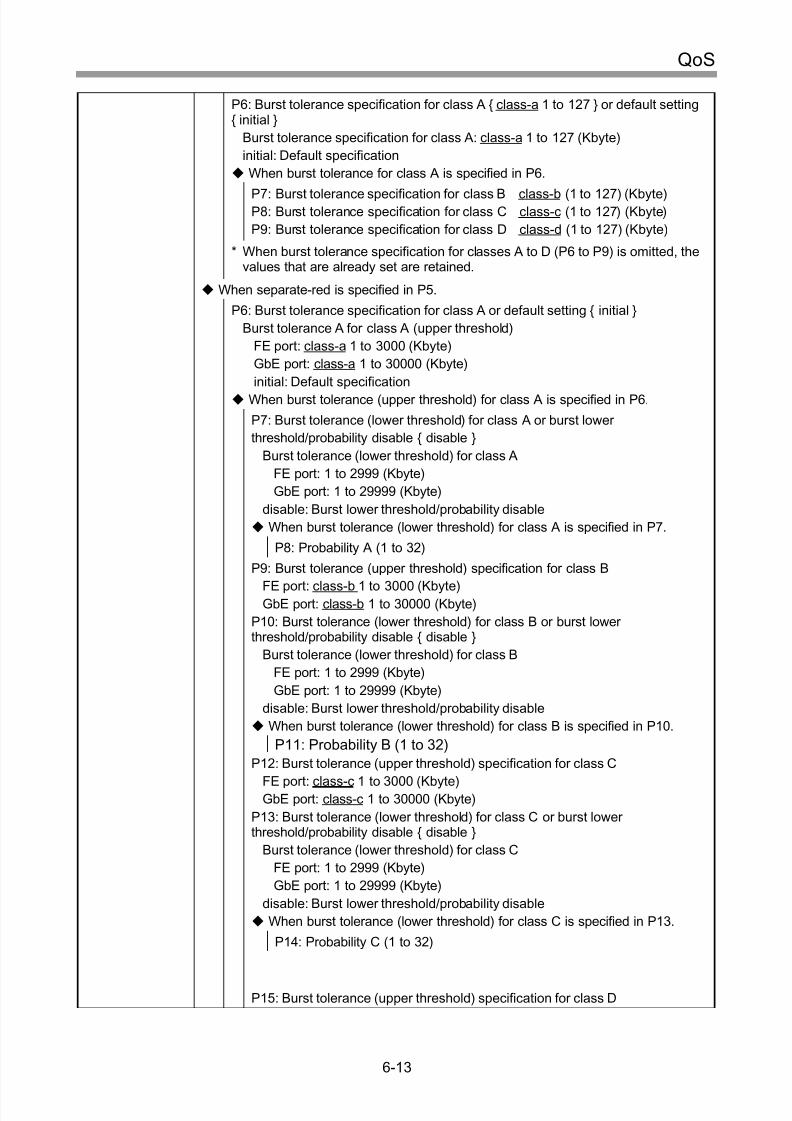
Setting of priority discard function per input VLAN...................................................6-12
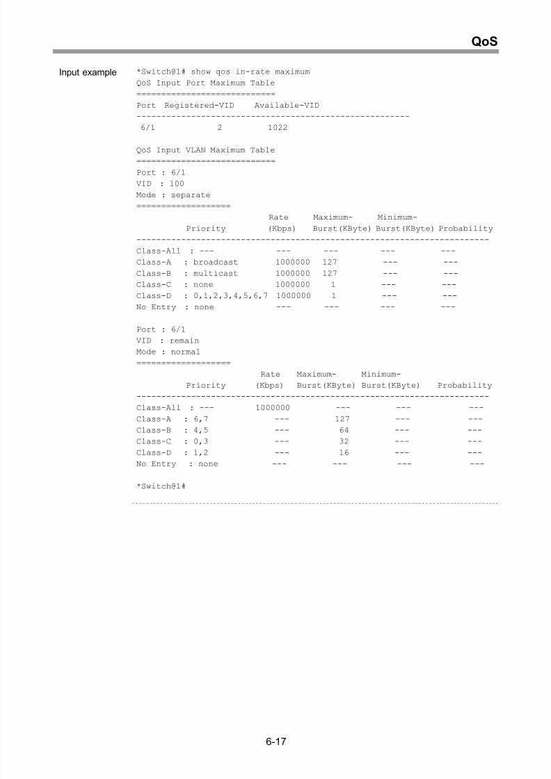
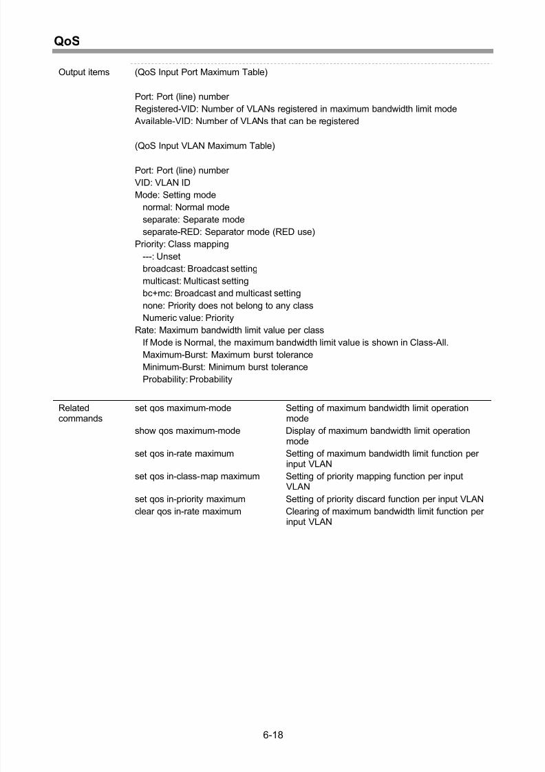
Display of maximum bandwidth limit function per input VLAN..................................6-16
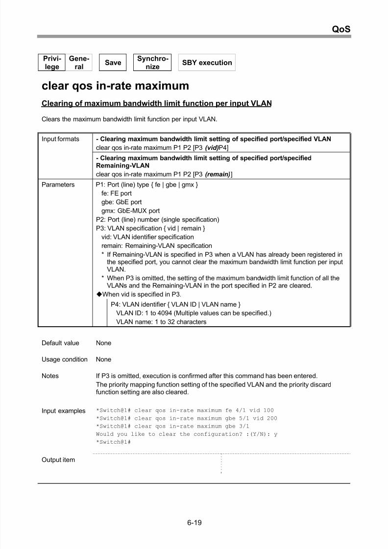
Clearing of maximum bandwidth limit function per input VLAN................................6-19
Setting of maximum bandwidth limit function per output VLAN................................6-21
Setting of priority mapping function per output VLAN...............................................6-24
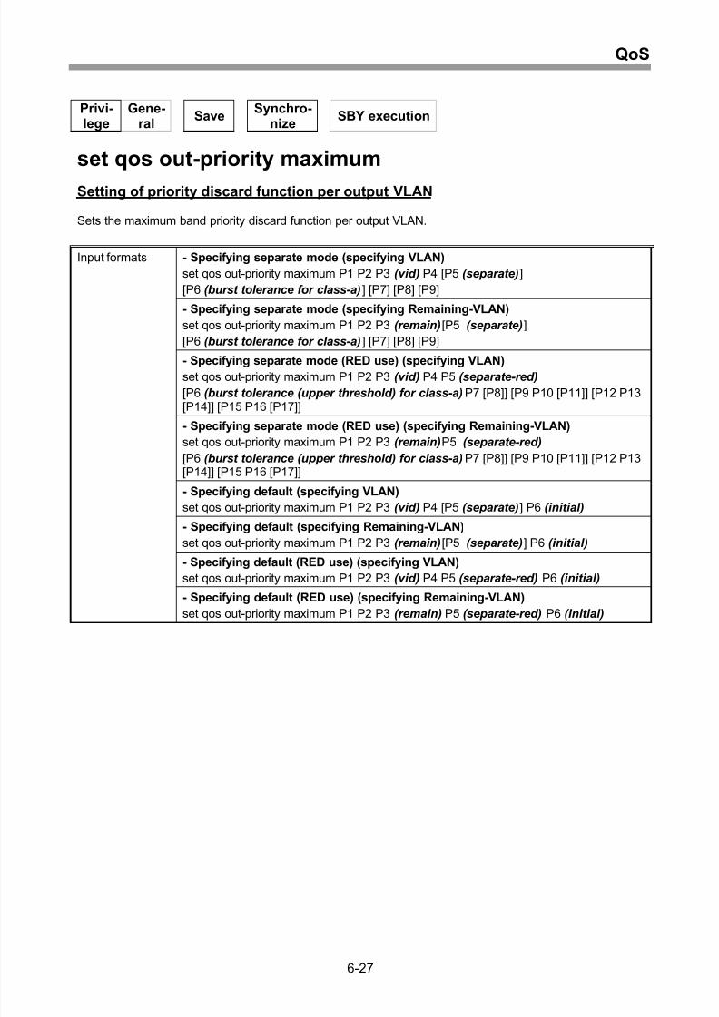
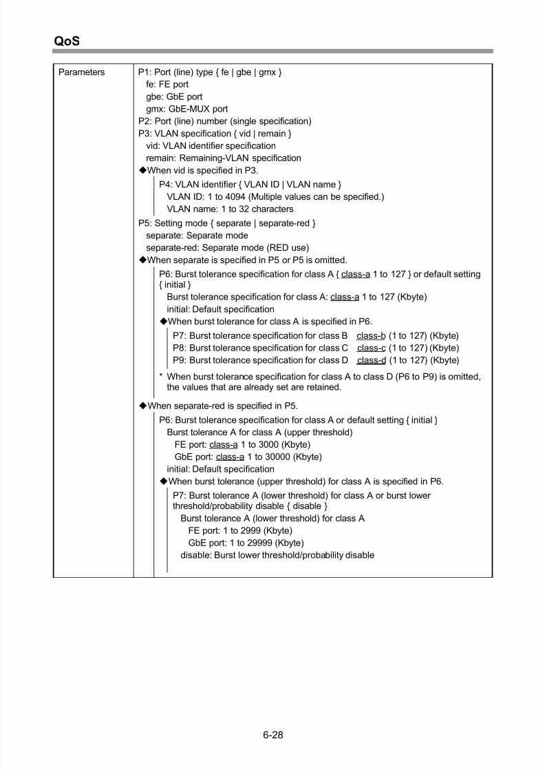
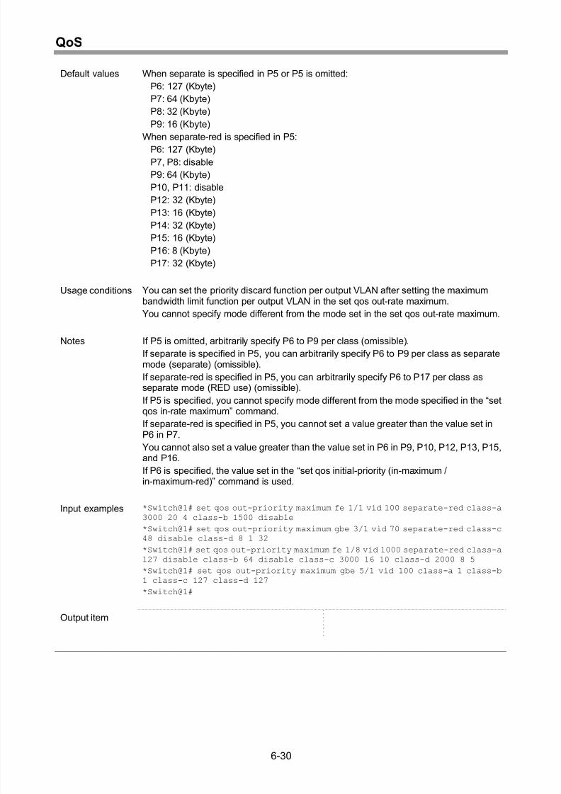
Setting of priority discard function per output VLAN.................................................6-27
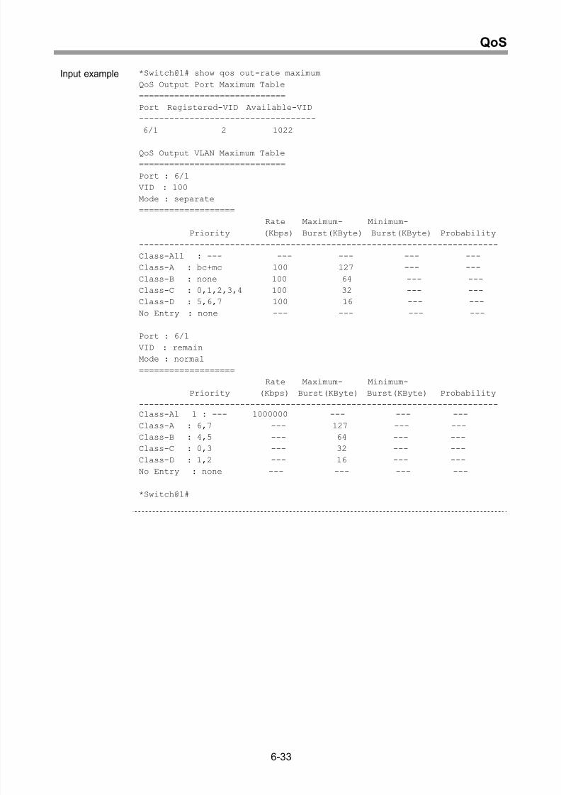
Display of maximum bandwidth limit function per output VLAN ...............................6-32
Clearing of maximum bandwidth limit function per output VLAN..............................6-35
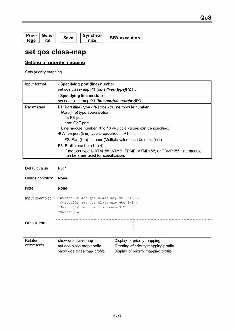
Setting of priority mapping........................................................................................6-37
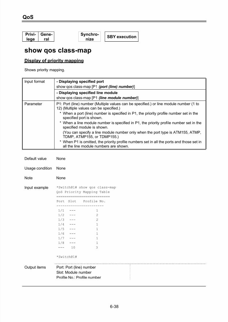
Display of priority mapping.......................................................................................6-38
ix
Page 14
8/21/2019 CX2600-220_Command_Reference_v7.6B_eng - Copy.pdf
http://slidepdf.com/reader/full/cx2600-220commandreferencev76beng-copypdf 14/758
Contents
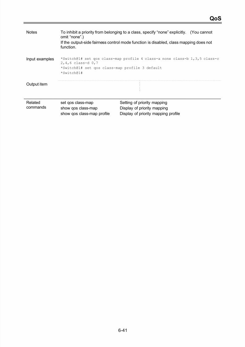
Creating of priority mapping profile...........................................................................6-40
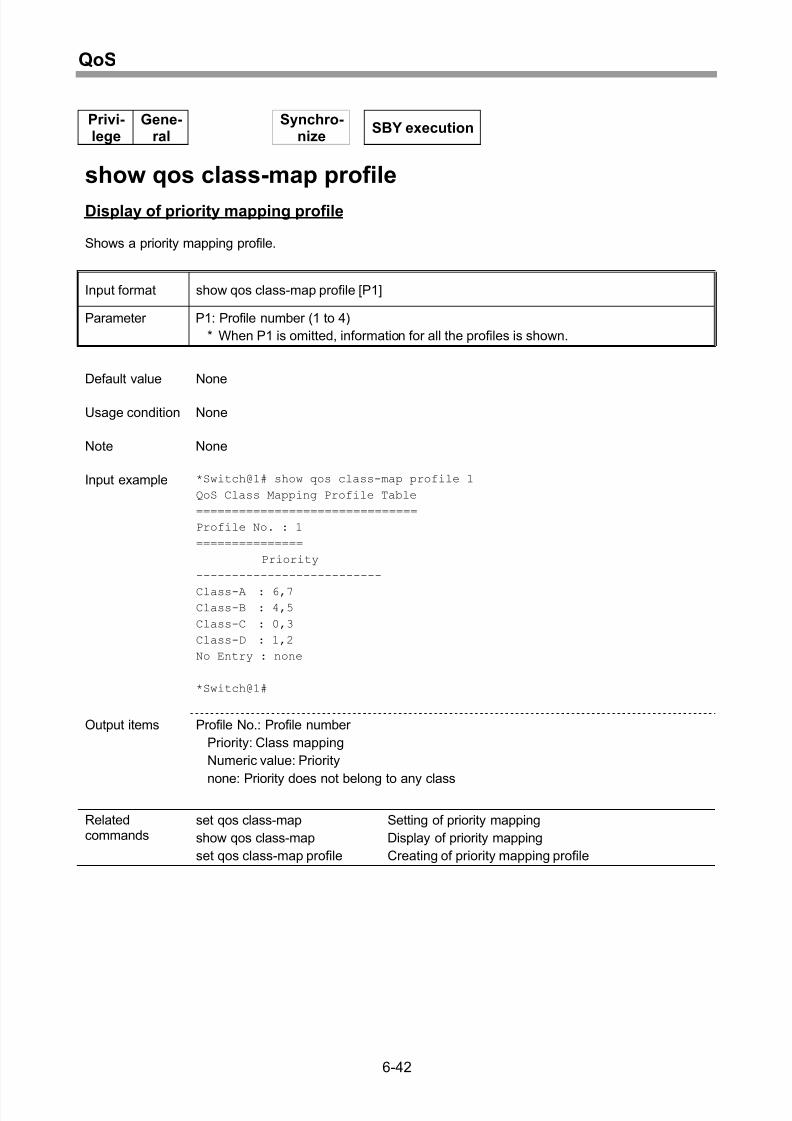
Display of priority mapping profile ............................................................................6-42
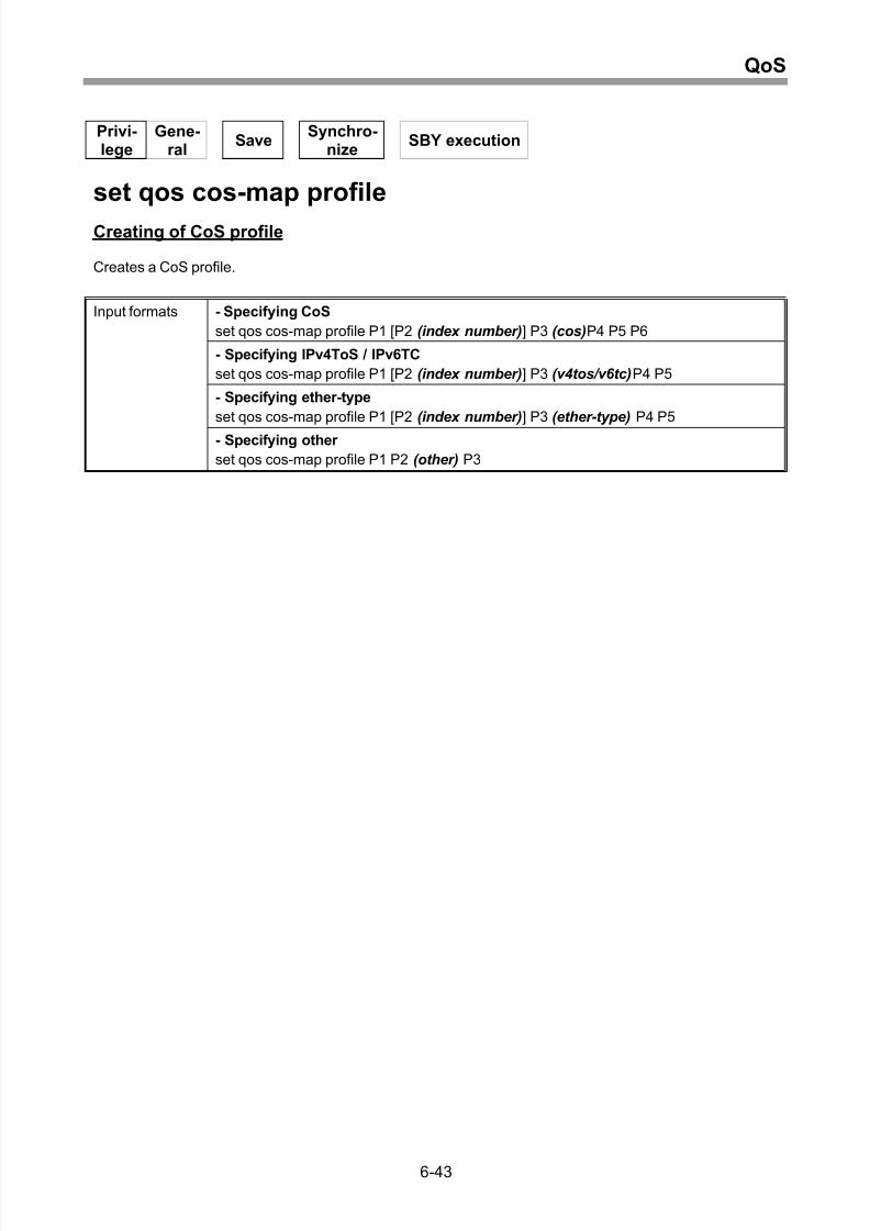
Creating of CoS profile.............................................................................................6-43
Display of CoS profile...............................................................................................6-46
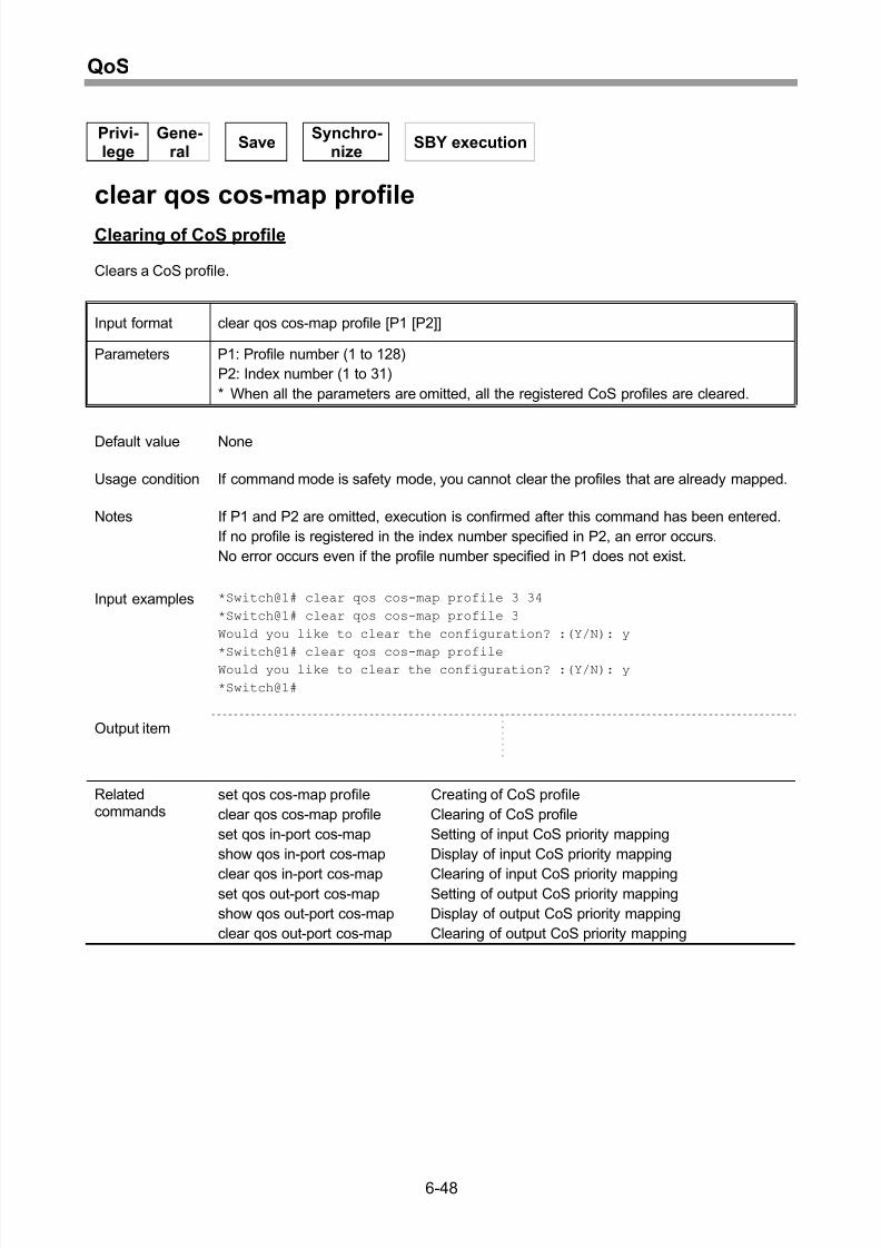
Clearing of CoS profile .............................................................................................6-48
Setting of input CoS priority mapping.......................................................................6-49
Display of input CoS priority mapping ......................................................................6-50
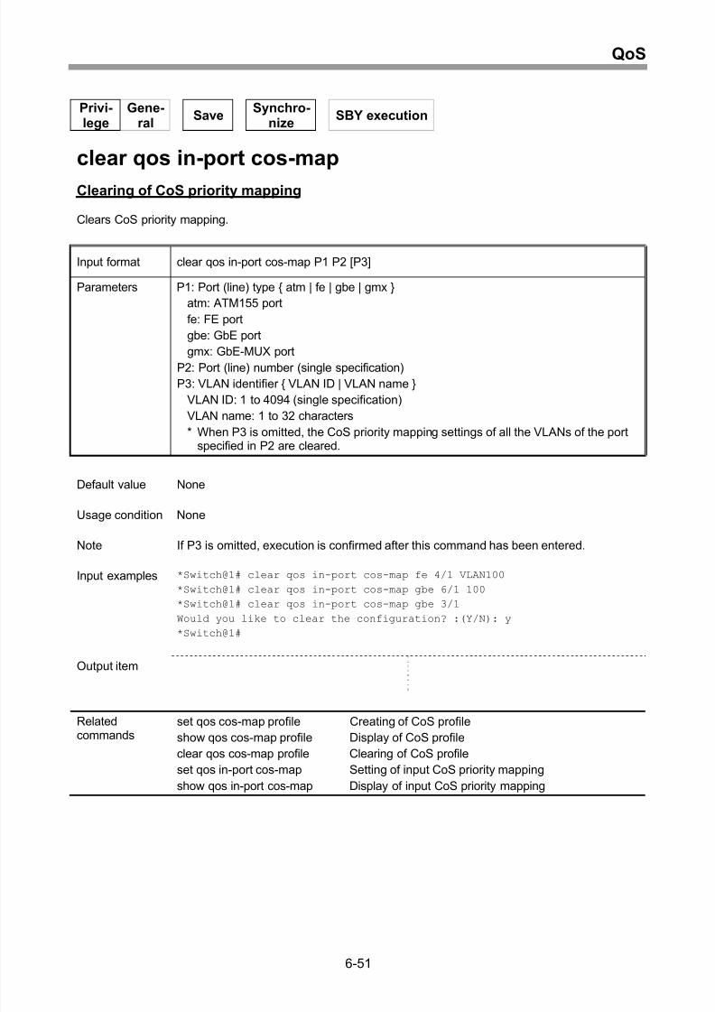
Clearing of CoS priority mapping .............................................................................6-51
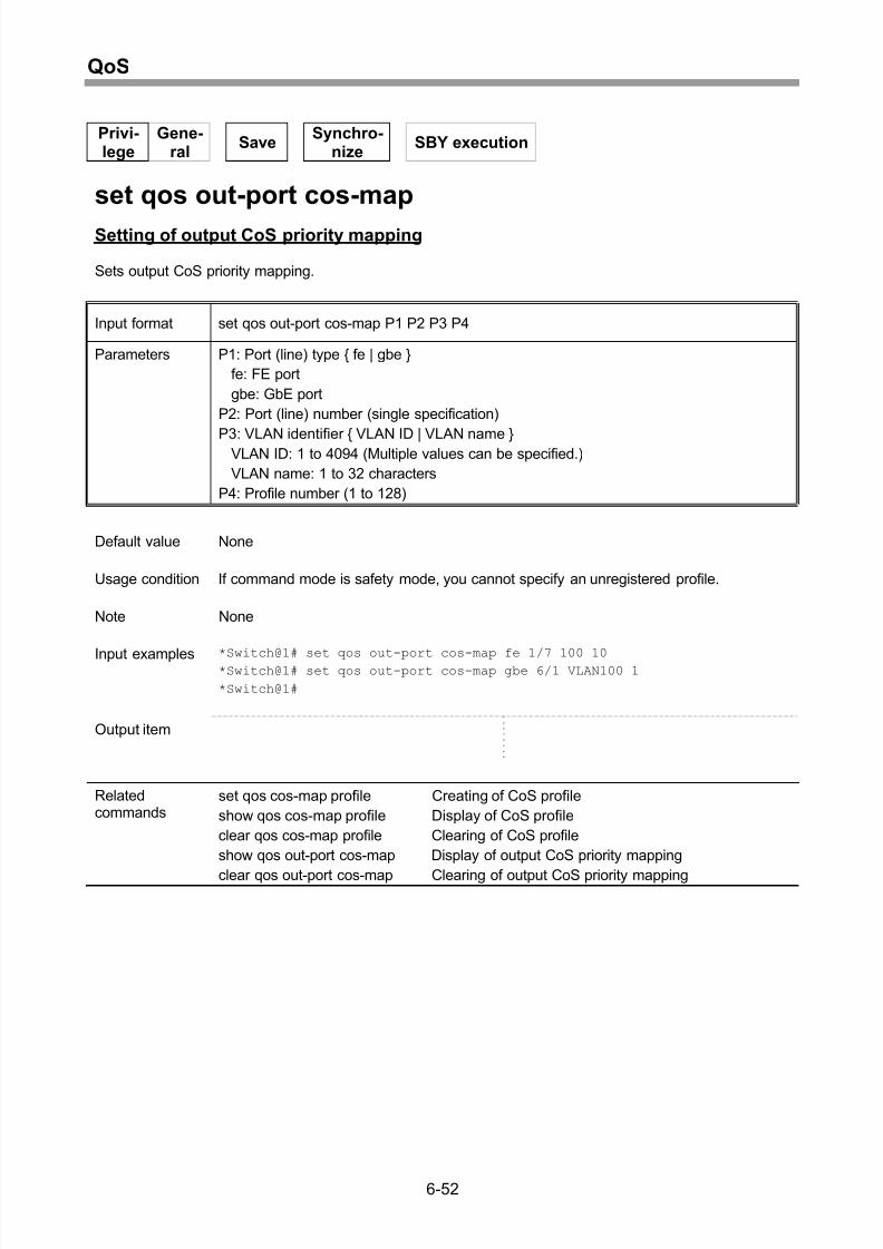
Setting of output CoS priority mapping.....................................................................6-52
Display of output CoS priority mapping ....................................................................6-53
Clearing of output CoS priority mapping...................................................................6-54
Setting of output-side fairness control mode function...............................................6-55
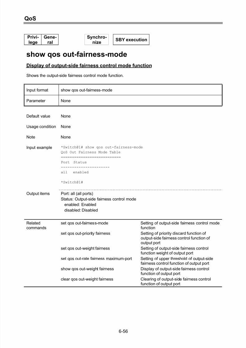
Display of output-side fairness control mode function..............................................6-56
Setting of priority discard function of output-side fairness control function of output
port...........................................................................................................................6-57
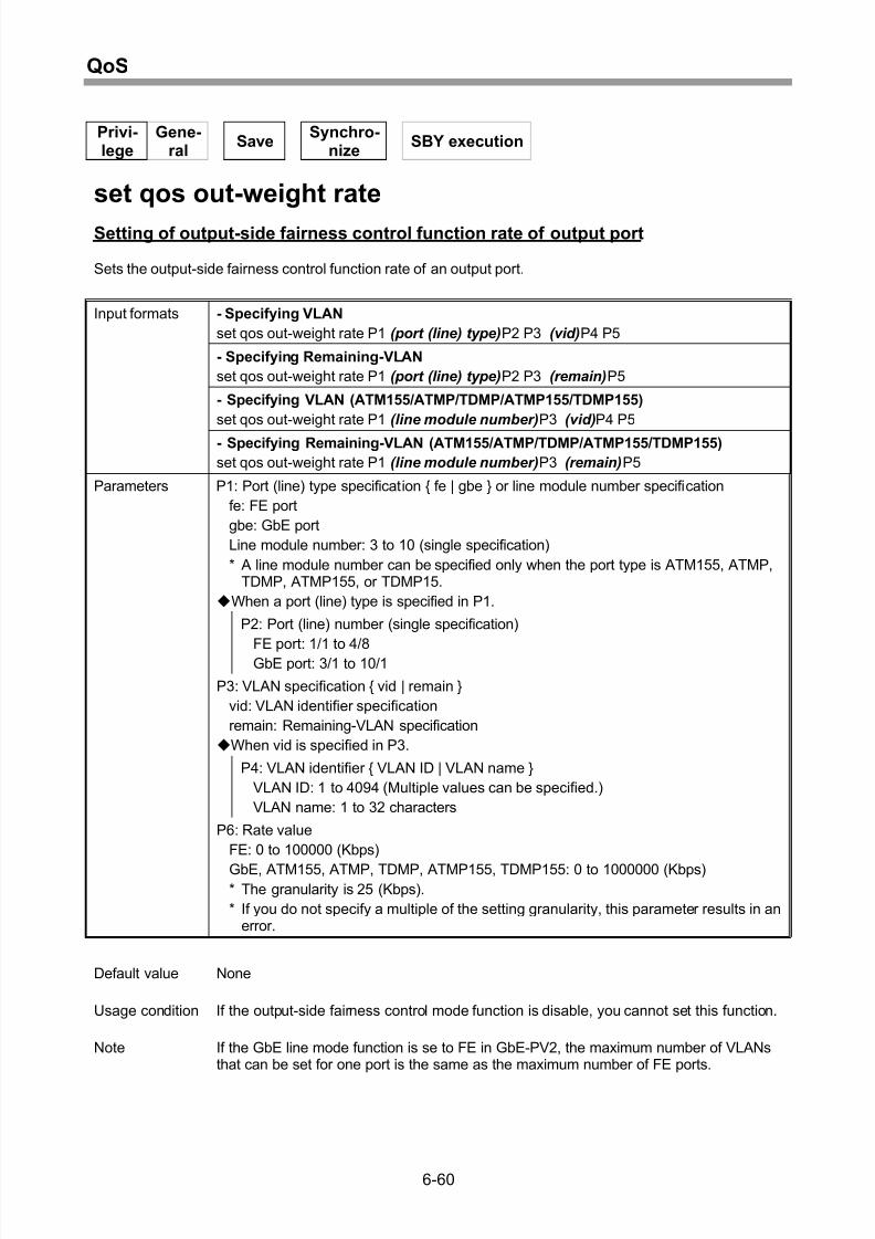
Setting of output-side fairness control function rate of output port ...........................6-60
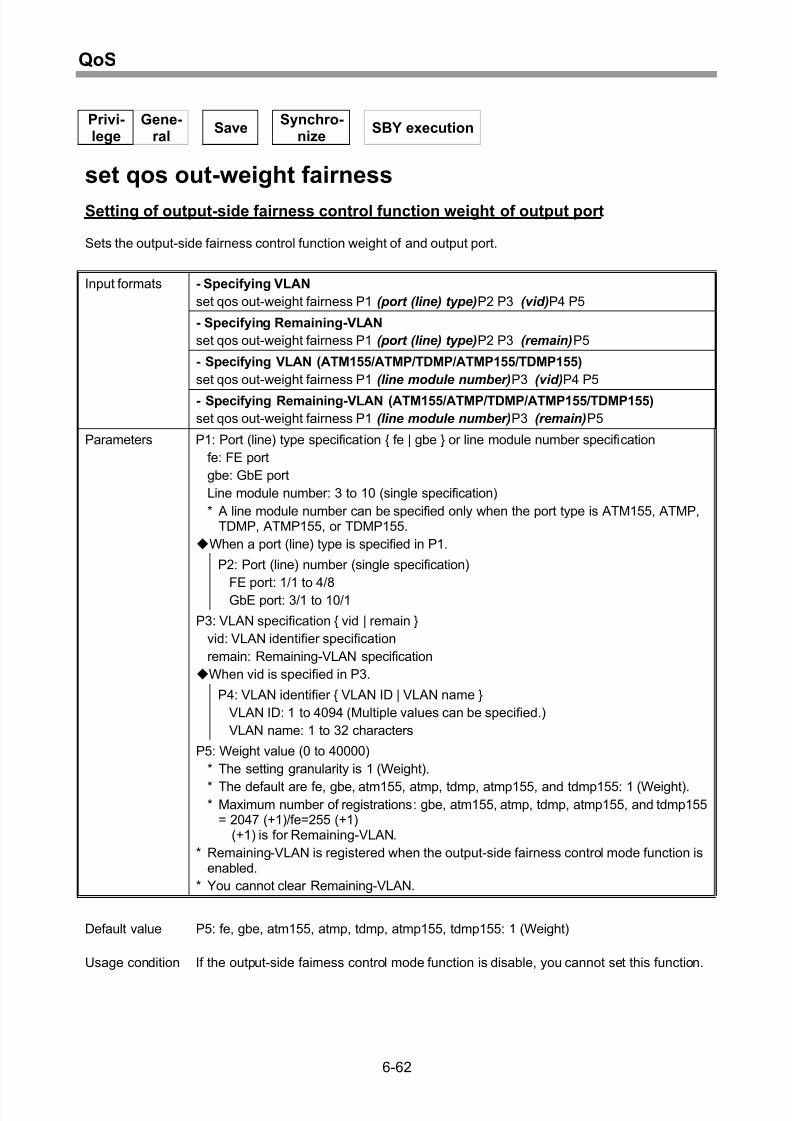
Setting of output-side fairness control function weight of output port .......................6-62
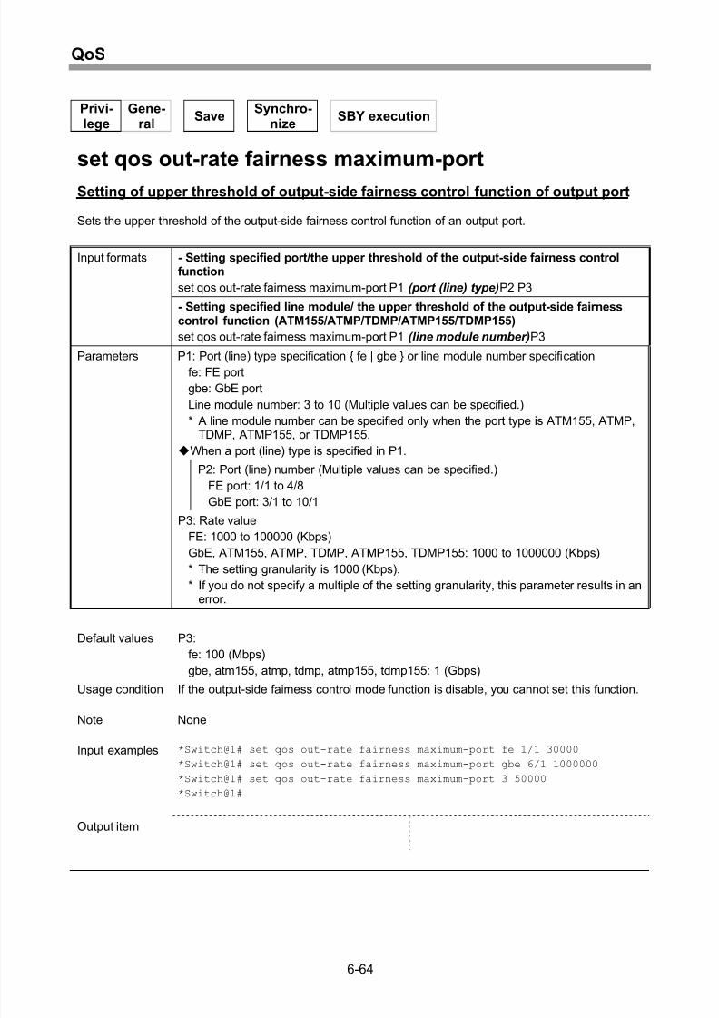
Setting of upper threshold of output-side fairness control function of output port.....6-64
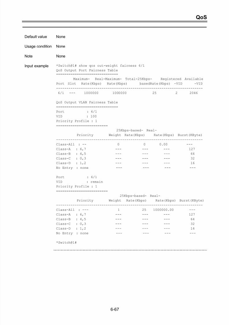
Display of output-side fairness control function of output port..................................6-66
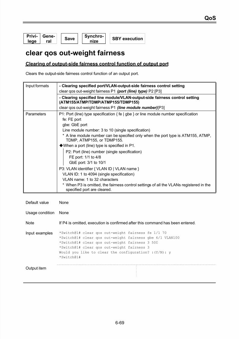
Clearing of output-side fairness control function of output port ................................6-69
Setting of default priority mapping............................................................................6-71
Display of default priority mapping ...........................................................................6-73
Setting of default burst tolerance..............................................................................6-75
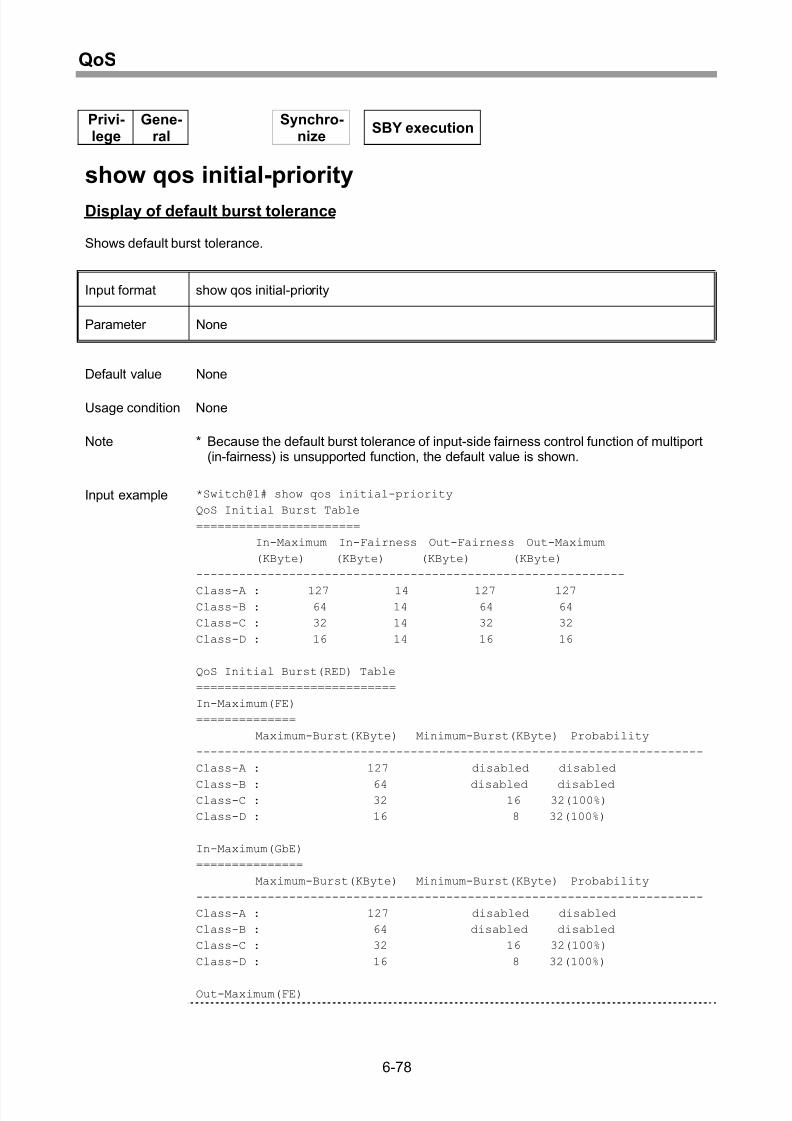
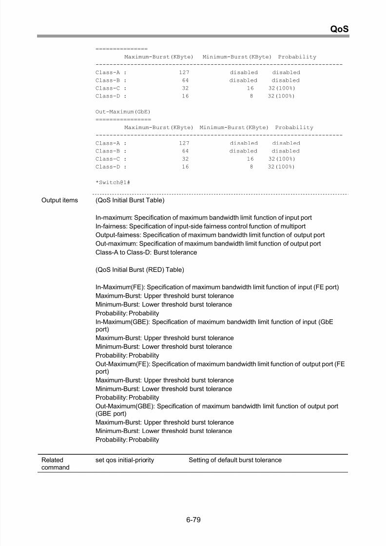
Display of default burst tolerance .............................................................................6-78
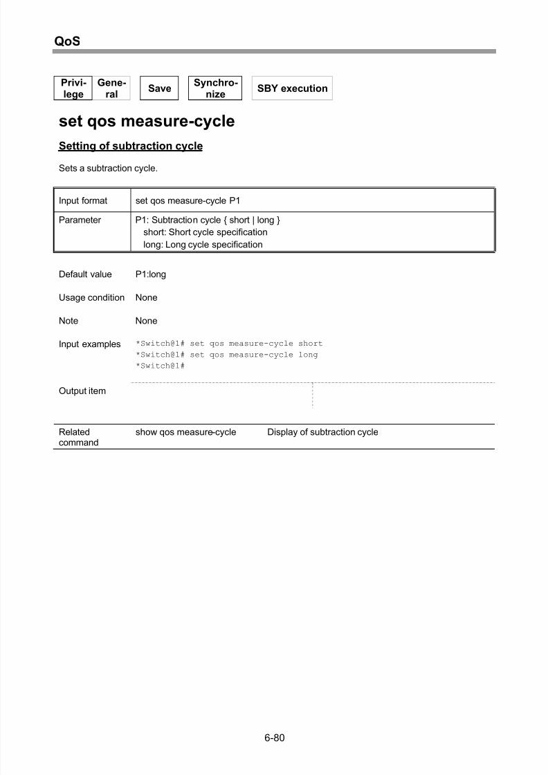
Setting of subtraction cycle ......................................................................................6-80
Display of subtraction cycle......................................................................................6-81
7 Switch Control ..........................................................................7-1
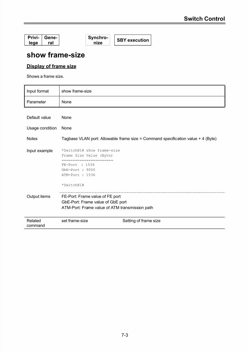
Setting of frame size.................................................................................................. 7-2
Display of frame size................................................................................................. 7-3
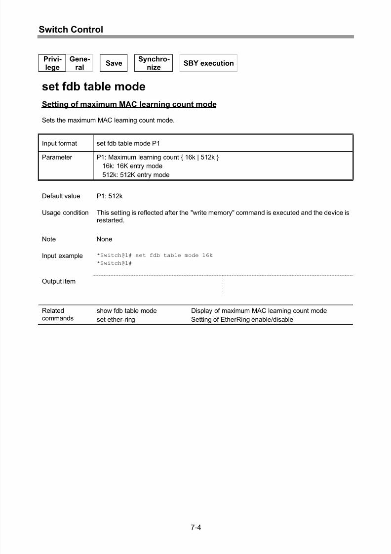
Setting of maximum MAC learning count mode ........................................................ 7-4
Display of maximum MAC learning count mode........................................................ 7-5
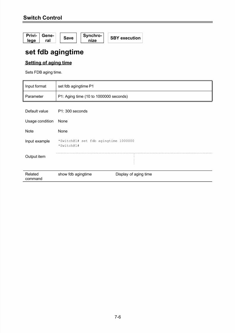
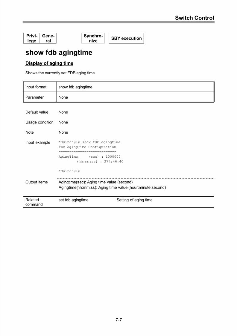
Setting of aging time.................................................................................................. 7-6
Display of aging time................................................................................................. 7-7
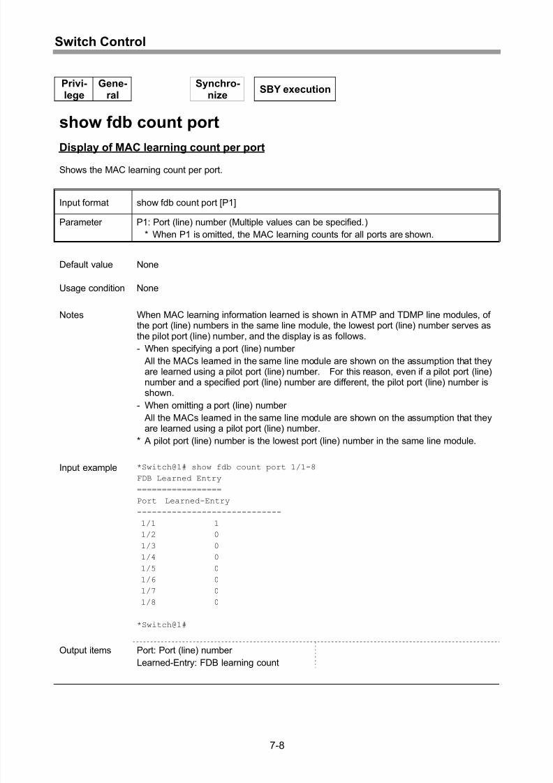
Display of MAC learning count per port..................................................................... 7-8
Display of MAC learning count per VLAN.................................................................7-10
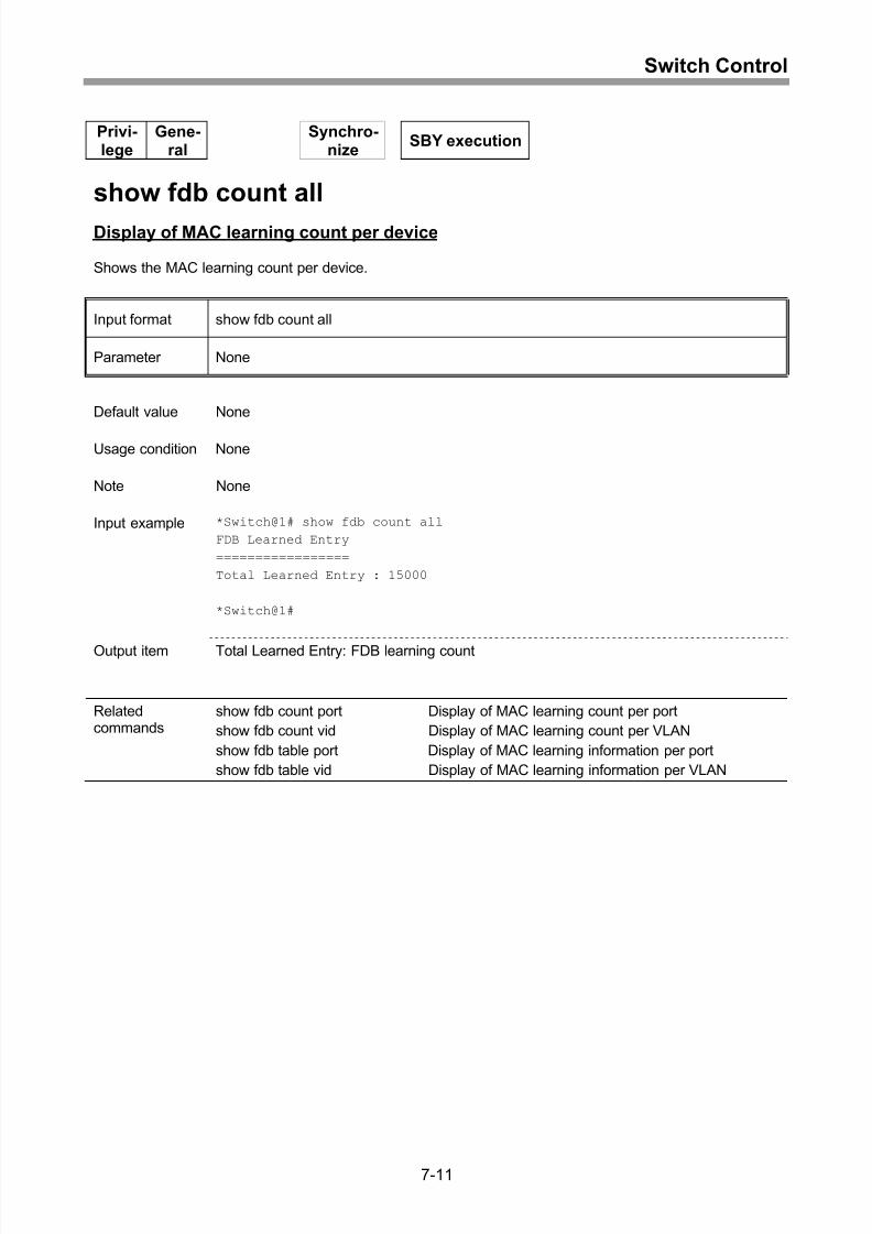
Display of MAC learning count per device................................................................7-11
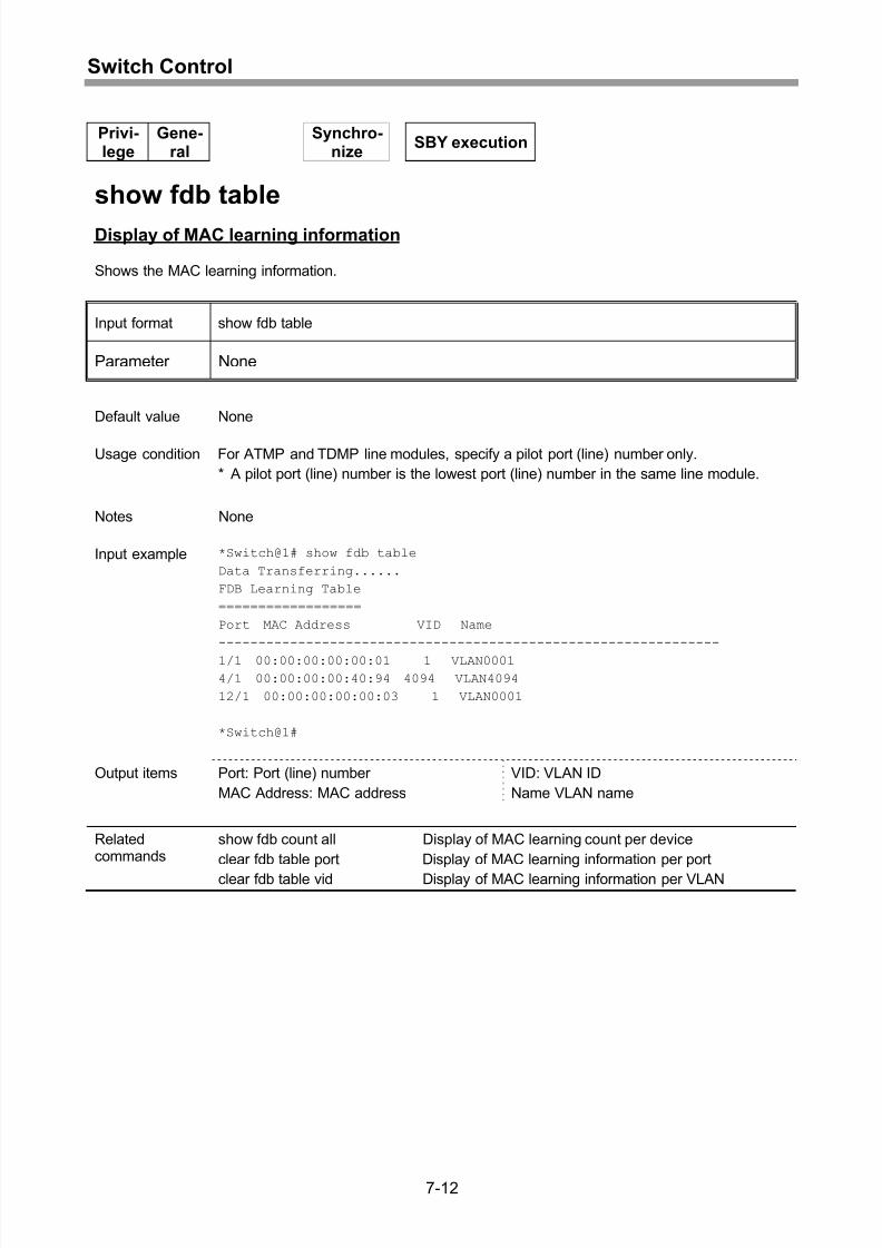
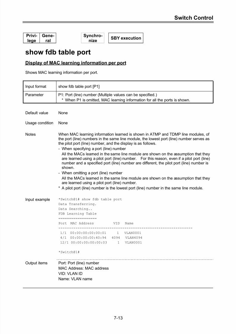
Display of MAC learning information ........................................................................7-12
x
Page 15
8/21/2019 CX2600-220_Command_Reference_v7.6B_eng - Copy.pdf
http://slidepdf.com/reader/full/cx2600-220commandreferencev76beng-copypdf 15/758
Contents
Display of MAC learning information per port...........................................................7-13
Clearing of MAC learning information per port .........................................................7-15
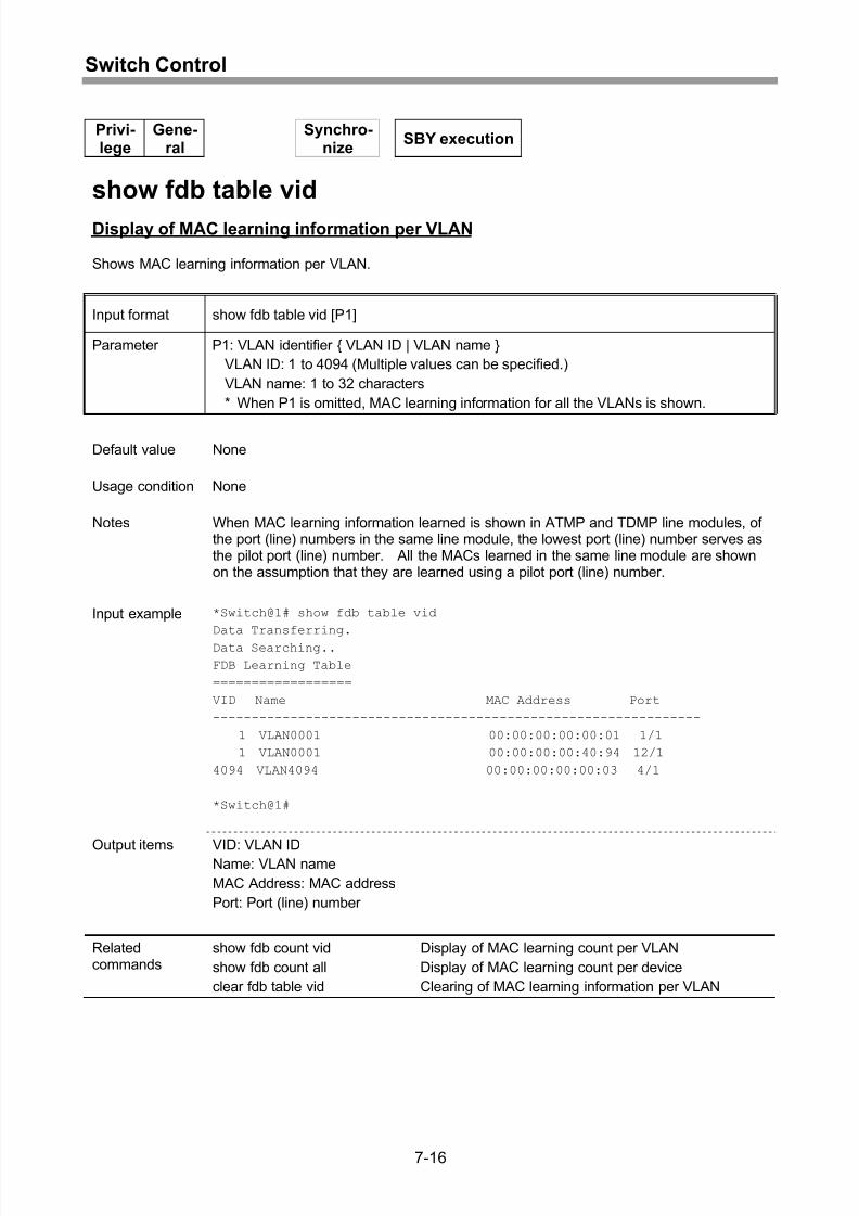
Display of MAC learning information per VLAN........................................................7-16
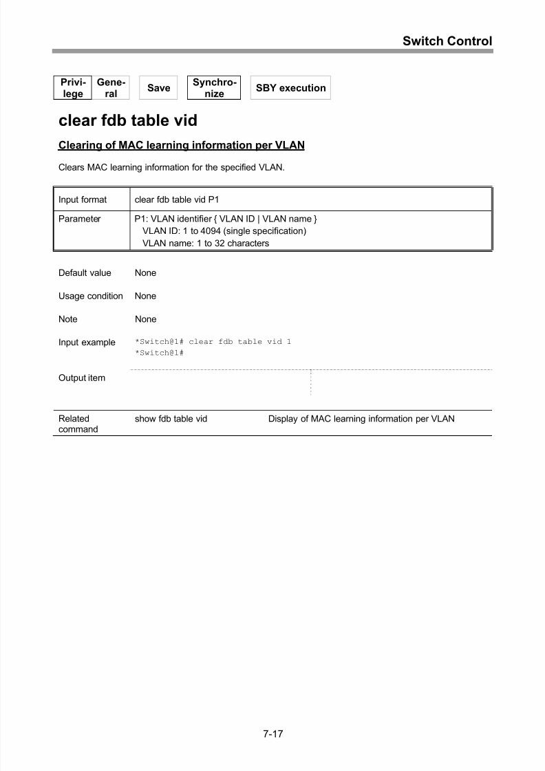
Clearing of MAC learning information per VLAN ......................................................7-17
Setting of IFG overrate mode...................................................................................7-18
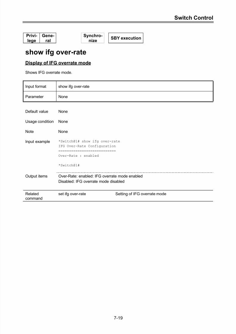
Display of IFG overrate mode ..................................................................................7-19
8 Route Control............................................................................8-1
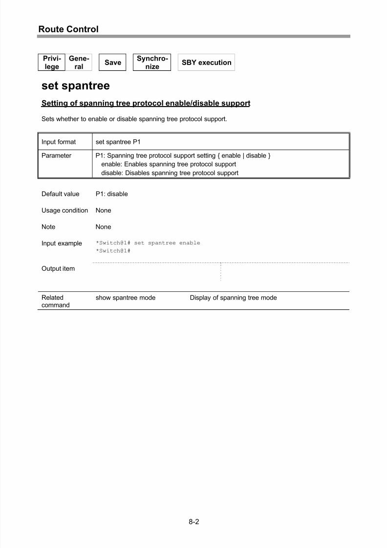
Setting of spanning tree protocol enable/disable support.......................................... 8-2
Setting of spanning tree mode .................................................................................. 8-3
Display of spanning tree mode.................................................................................. 8-4
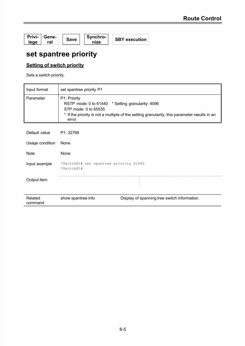
Setting of switch priority ............................................................................................ 8-5
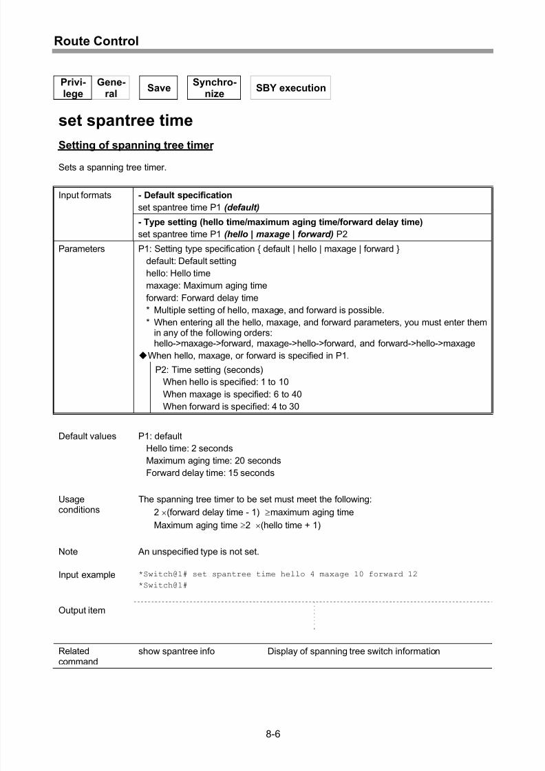
Setting of spanning tree timer ................................................................................... 8-6
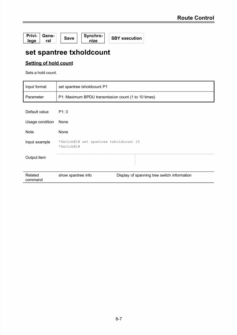
Setting of hold count.................................................................................................. 8-7
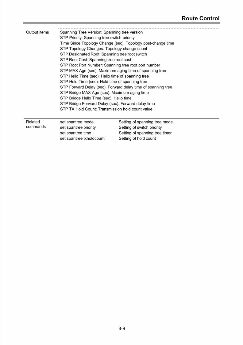
Display of spanning tree switch information .............................................................. 8-8
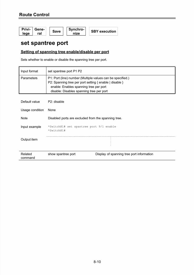
Setting of spanning tree enable/disable per port ......................................................8-10
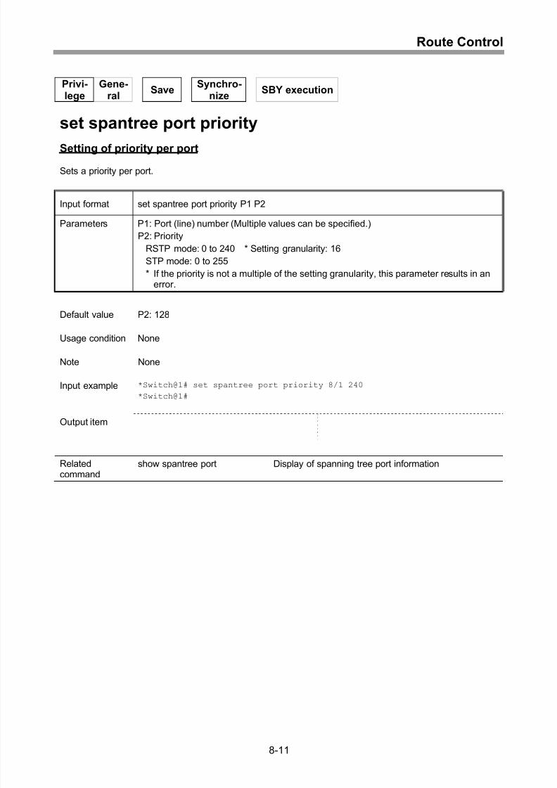
Setting of priority per port .........................................................................................8-11
Setting of path cost per port .....................................................................................8-12
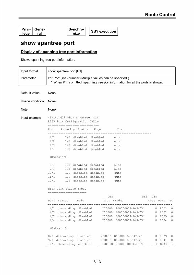
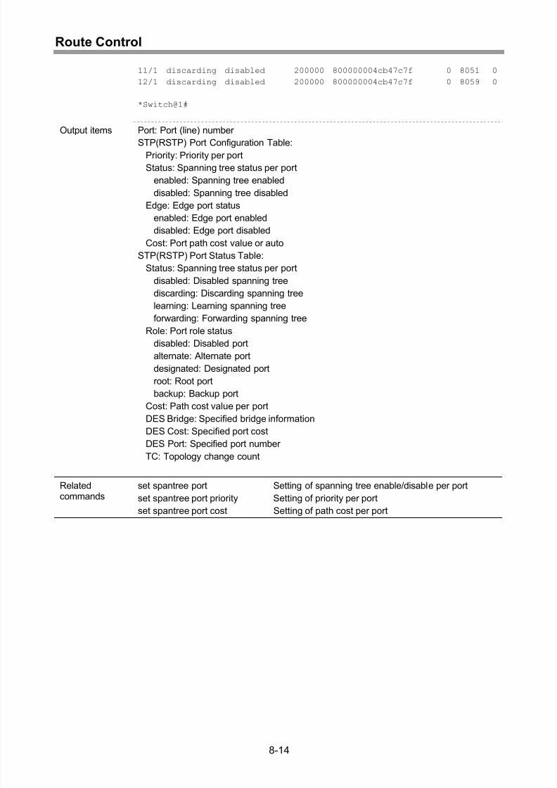
Display of spanning tree port information.................................................................8-13
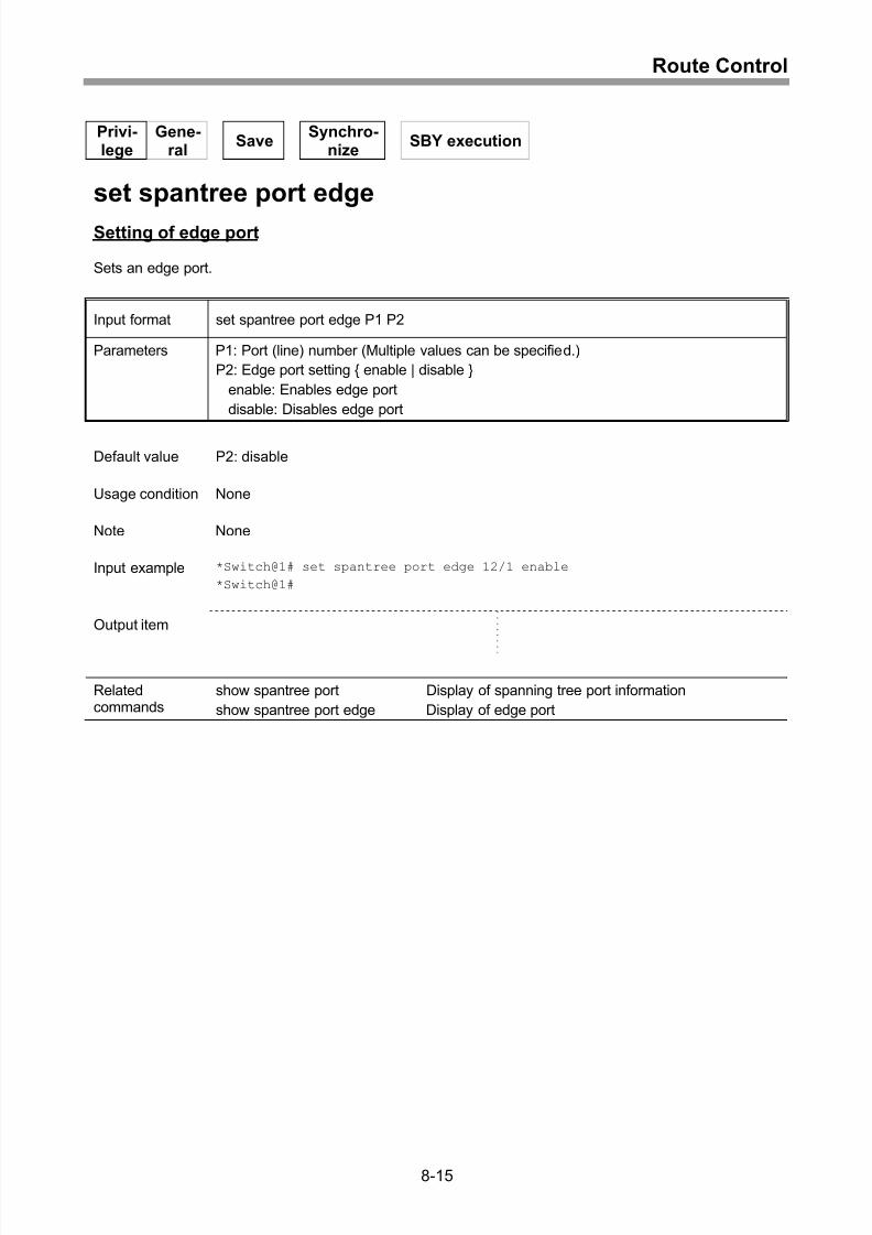
Setting of edge port..................................................................................................8-15
Display of edge port .................................................................................................8-16
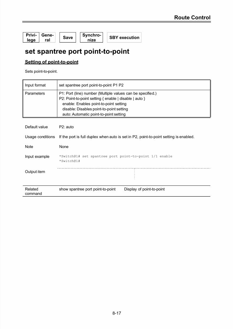
Setting of point-to-point ............................................................................................8-17
Display of point-to-point............................................................................................8-18
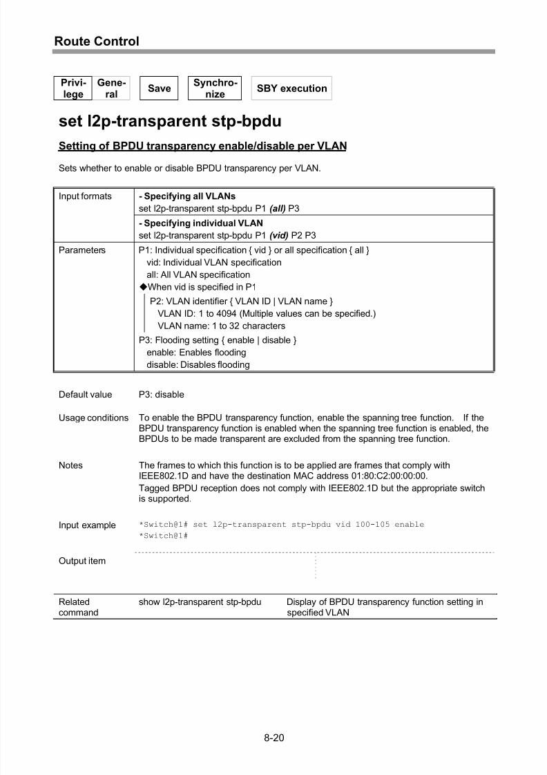
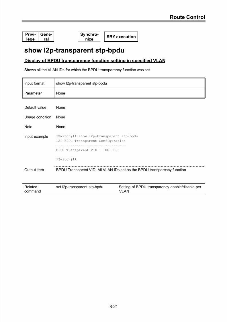
Setting of BPDU transparency enable/disable per VLAN.........................................8-20
Display of BPDU transparency function setting in specified VLAN...........................8-21
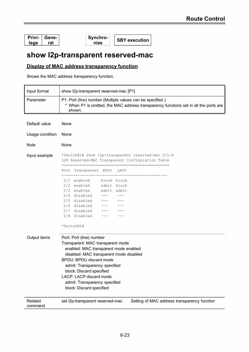
Setting of MAC address transparency function ........................................................8-22
Display of MAC address transparency function........................................................8-23
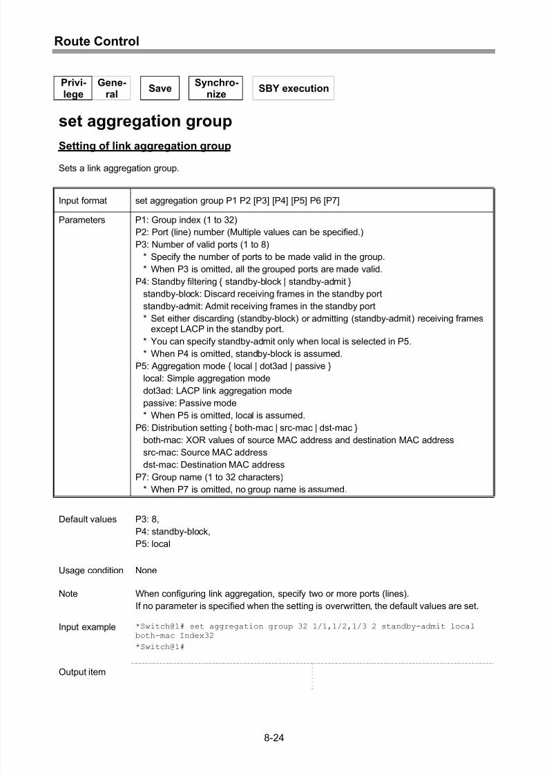
Setting of link aggregation group..............................................................................8-24
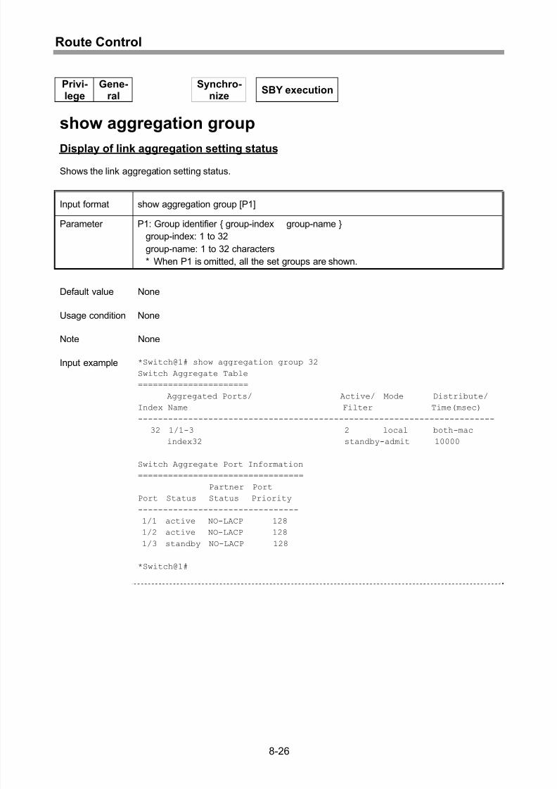
Display of link aggregation setting status .................................................................8-26
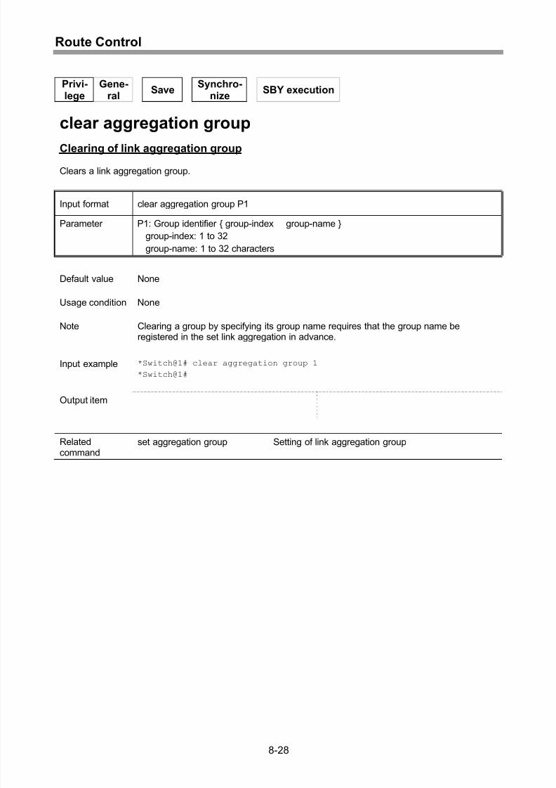
Clearing of link aggregation group ...........................................................................8-28
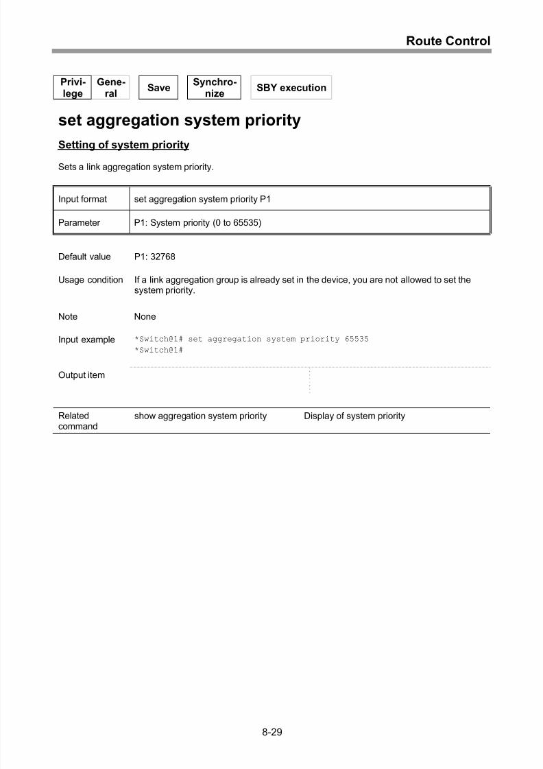
Setting of system priority..........................................................................................8-29
Display of system priority .........................................................................................8-30
Setting of port priority ...............................................................................................8-31
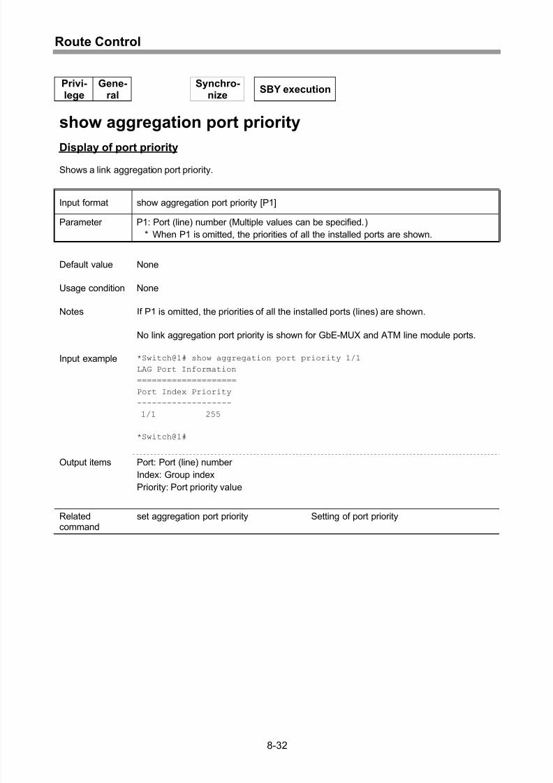
Display of port priority...............................................................................................8-32
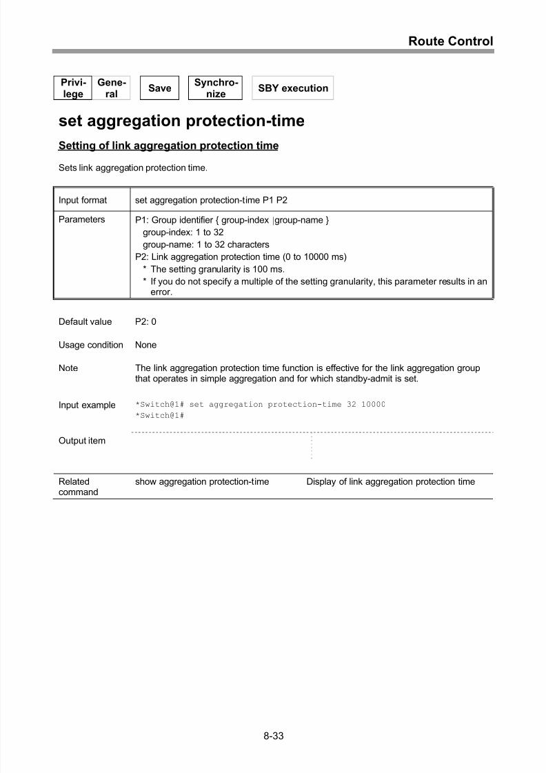
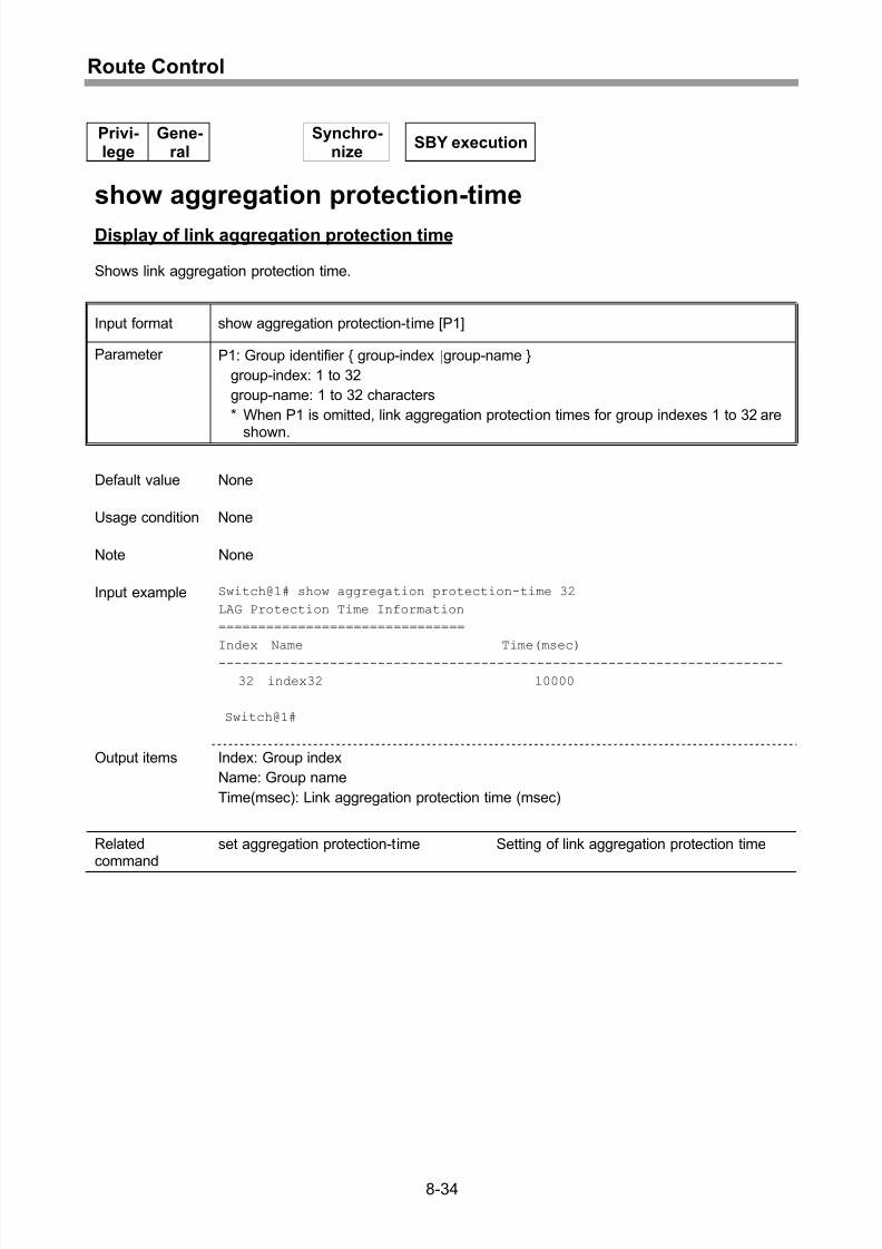
Setting of link aggregation protection time ...............................................................8-33
Display of link aggregation protection time...............................................................8-34
Setting of IGMP Snooping function enable/disable ..................................................8-35
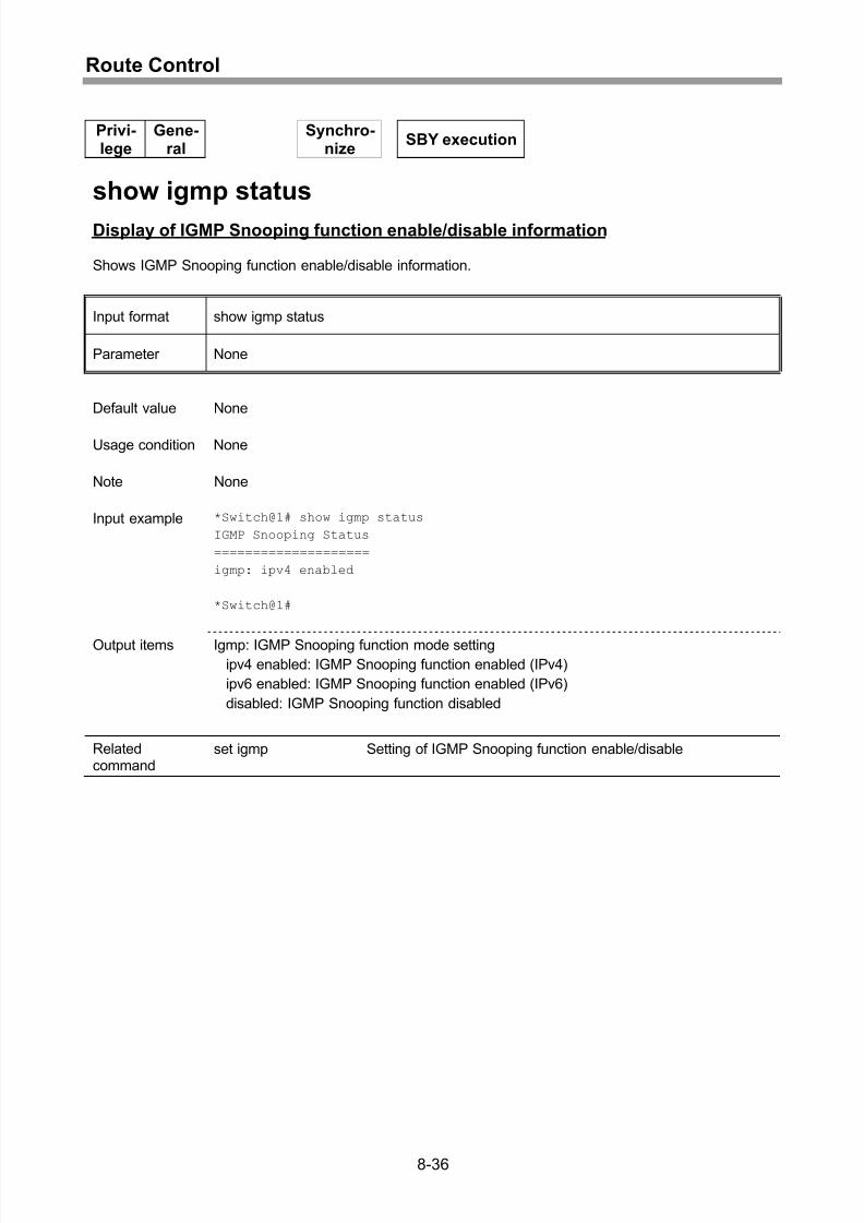
Display of IGMP Snooping function enable/disable information...............................8-36
xi
Page 16
8/21/2019 CX2600-220_Command_Reference_v7.6B_eng - Copy.pdf
http://slidepdf.com/reader/full/cx2600-220commandreferencev76beng-copypdf 16/758
Contents
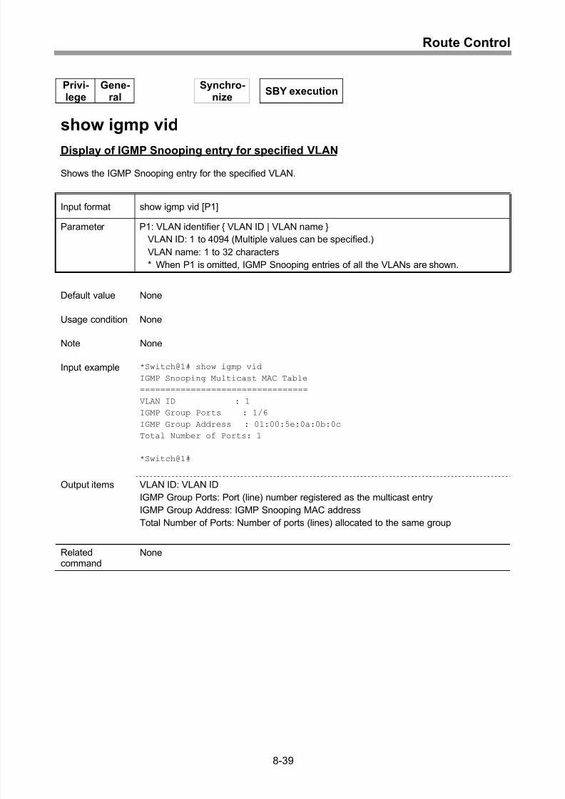
Display of IGMP Snooping entry for specified MAC .................................................8-37
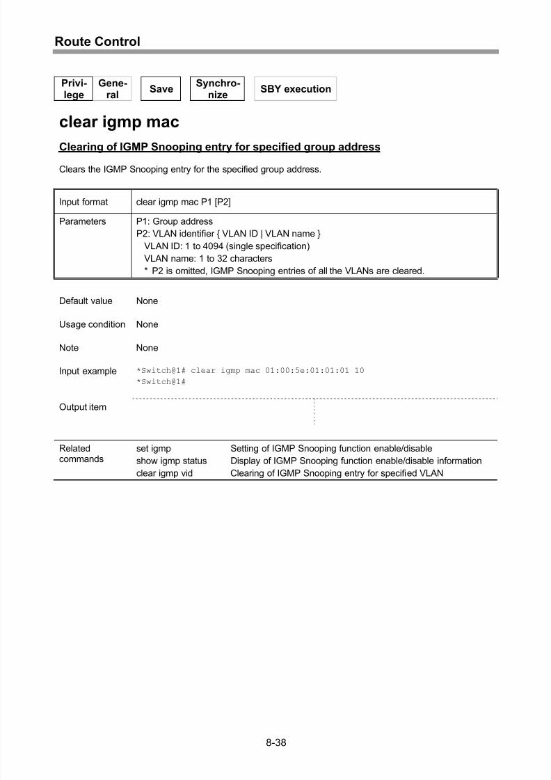
Clearing of IGMP Snooping entry for specified group address.................................8-38
Display of IGMP Snooping entry for specified VLAN................................................8-39
Display of IGMP Snooping entry for specified port number......................................8-40
Clearing of IGMP Snooping entry for specified VLAN ..............................................8-41
9 Filters .........................................................................................9-1
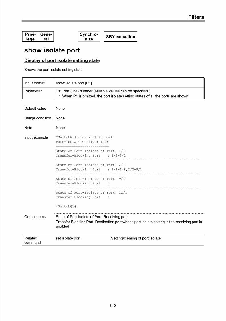
Setting/clearing of port isolate ................................................................................... 9-2
Display of port isolate setting state............................................................................ 9-3
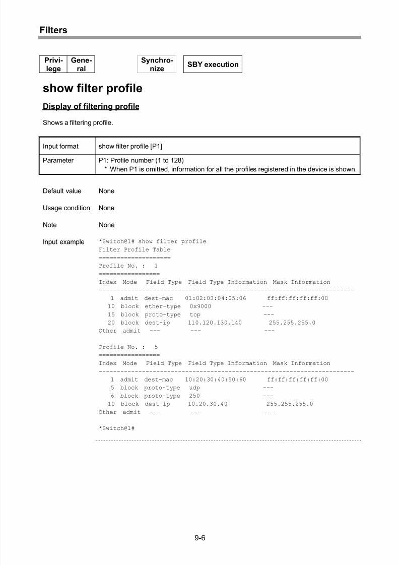
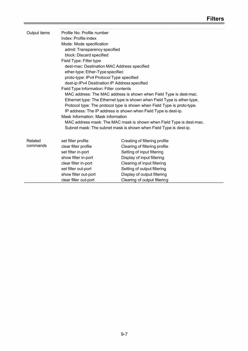
Creating of filtering profile ......................................................................................... 9-4
Display of filtering profile ........................................................................................... 9-6
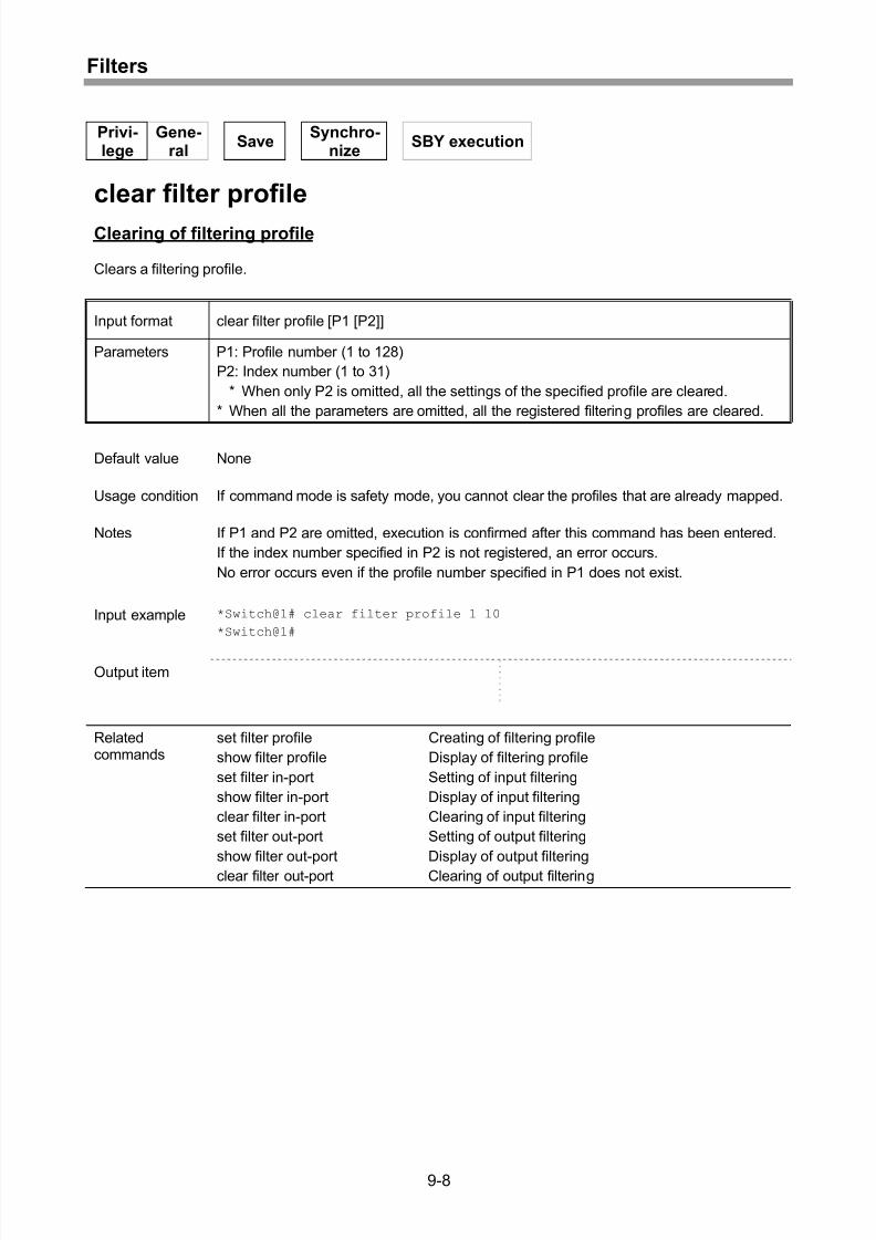
Clearing of filtering profile.......................................................................................... 9-8
Setting of input filtering.............................................................................................. 9-9
Display of input filtering ............................................................................................9-10
Clearing of input filtering...........................................................................................9-12
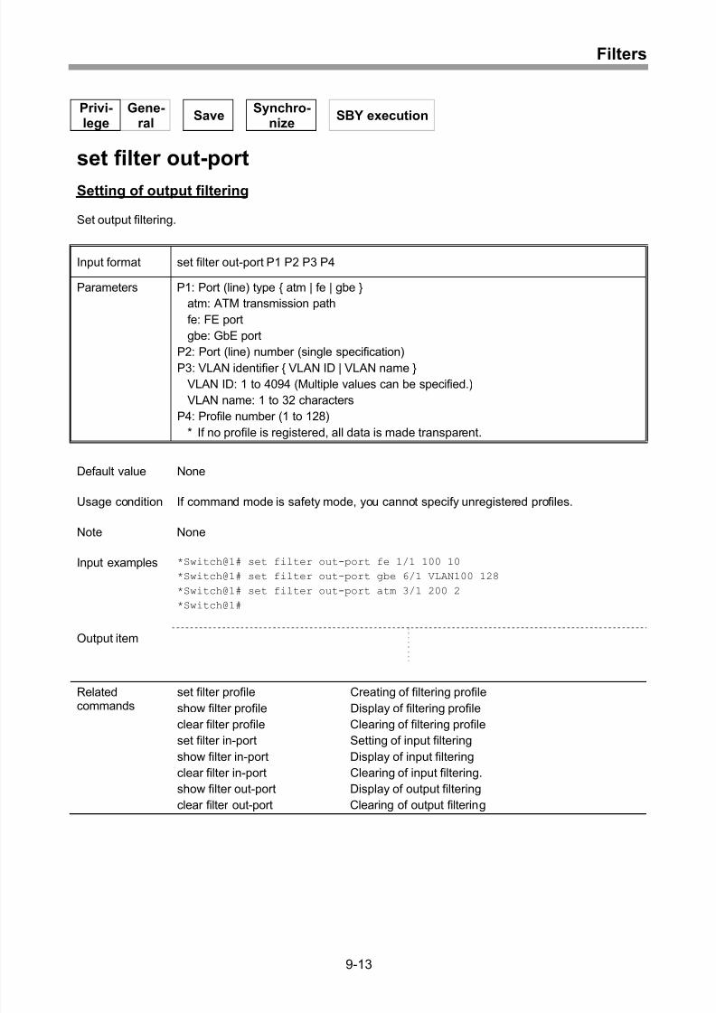
Setting of output filtering...........................................................................................9-13
Display of output filtering..........................................................................................9-14
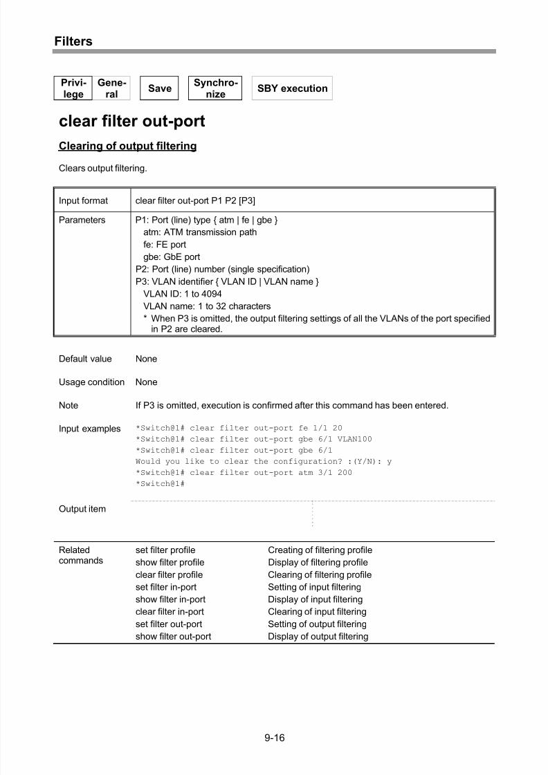
Clearing of output filtering ........................................................................................9-16
Setting of MAC address learning limiting count function ..........................................9-17
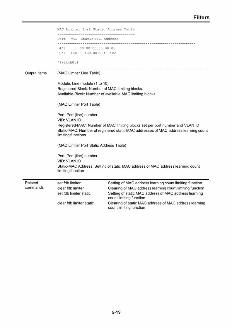
Display of MAC address learning count limiting function..........................................9-18
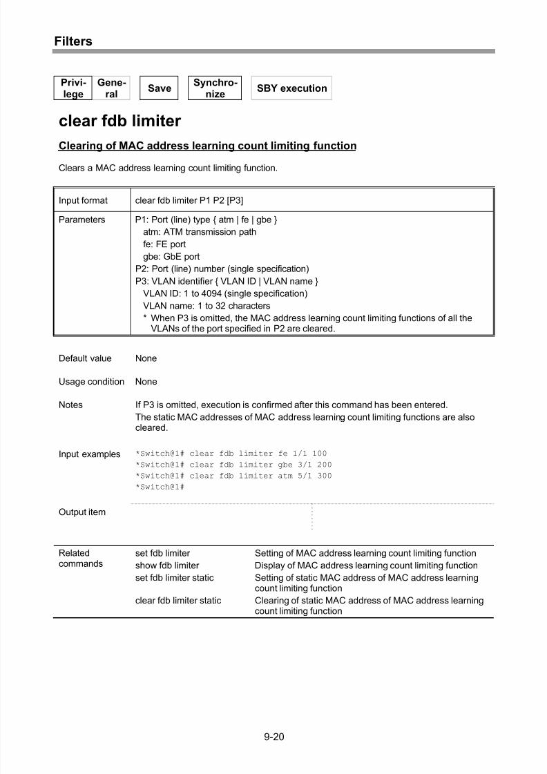
Clearing of MAC address learning count limiting function ........................................9-20
Setting of static MAC address of MAC address learning count limiting function ......9-21
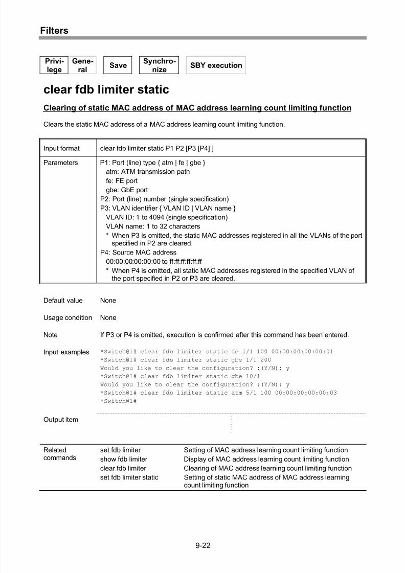
Clearing of static MAC address of MAC address learning count limiting function ....9-22
10 EtherOAM ..............................................................................10-1
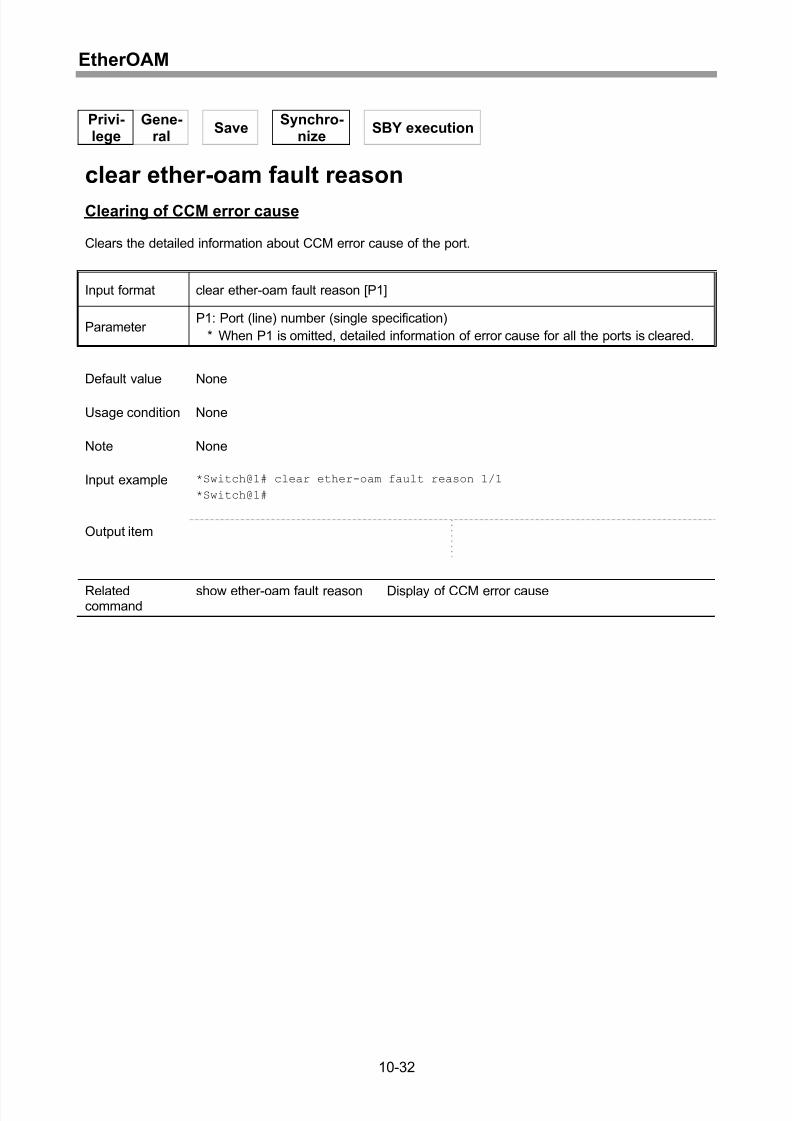
Setting of MEG.........................................................................................................10-2
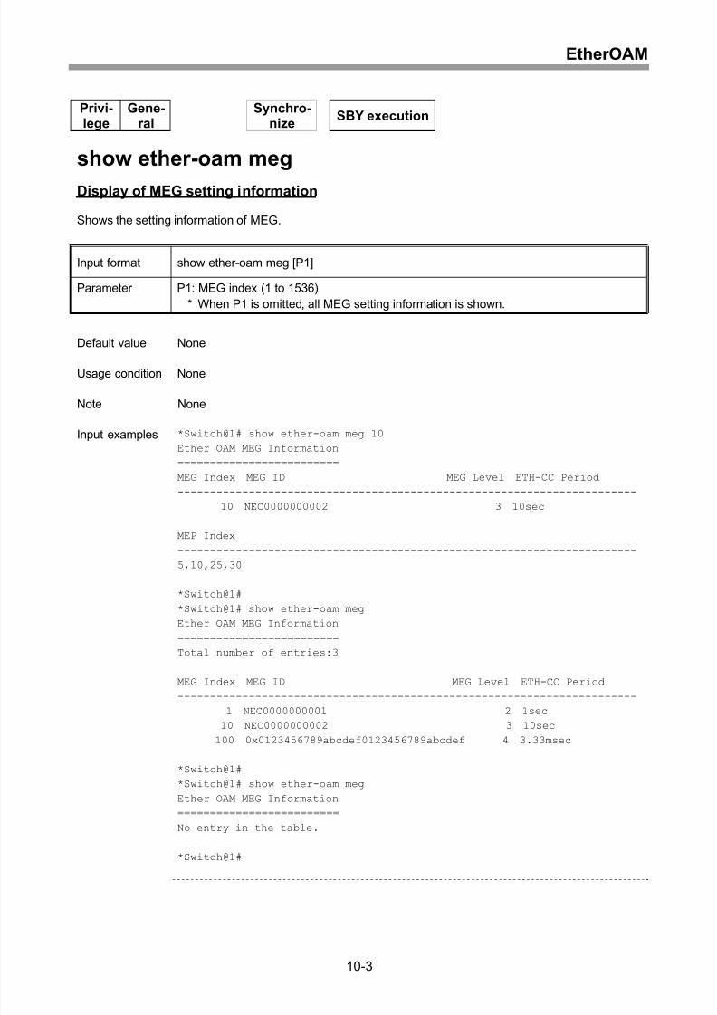
Display of MEG setting information ..........................................................................10-3
Clearing of MEG.......................................................................................................10-5
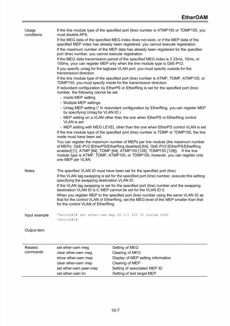
Setting of MEP .........................................................................................................10-6
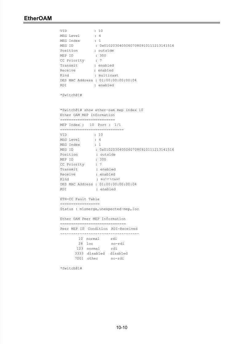
Display of MEP setting information ..........................................................................10-8
Clearing of MEP .....................................................................................................10-12
Setting of test target MEP ......................................................................................10-13
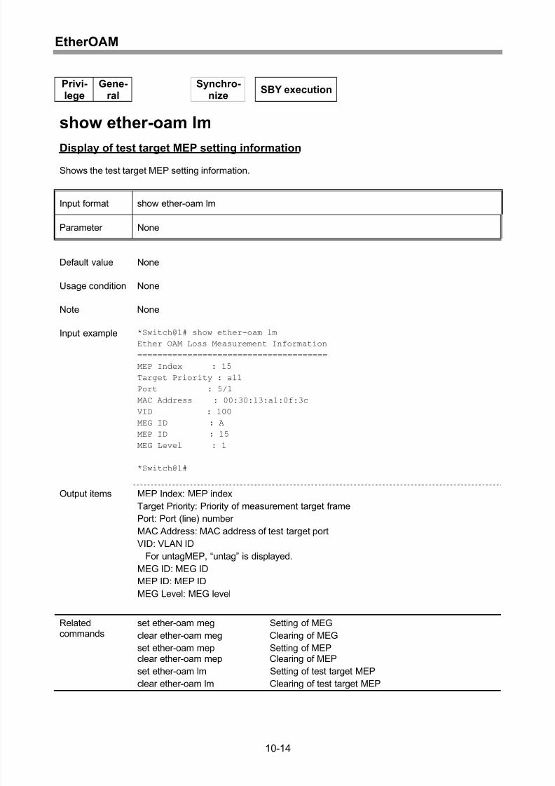
Display of test target MEP setting information........................................................10-14
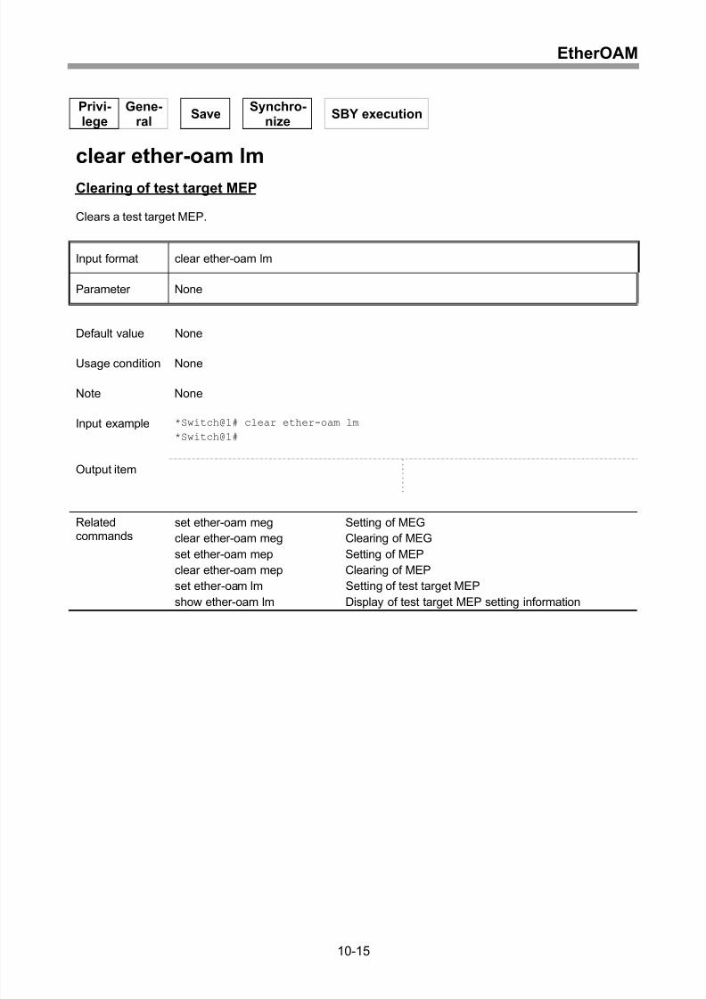
Clearing of test target MEP ....................................................................................10-15
Setting of associated MEP ID.................................................................................10-16
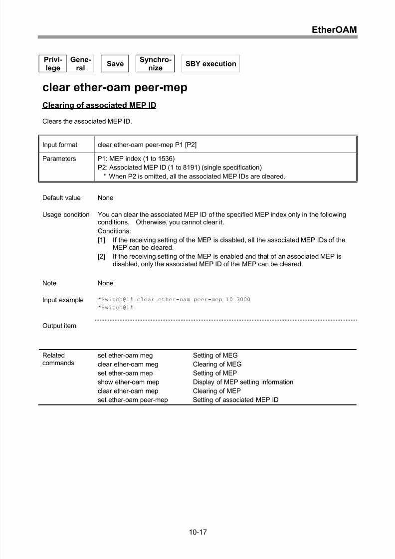
Clearing of associated MEP ID ..............................................................................10-17
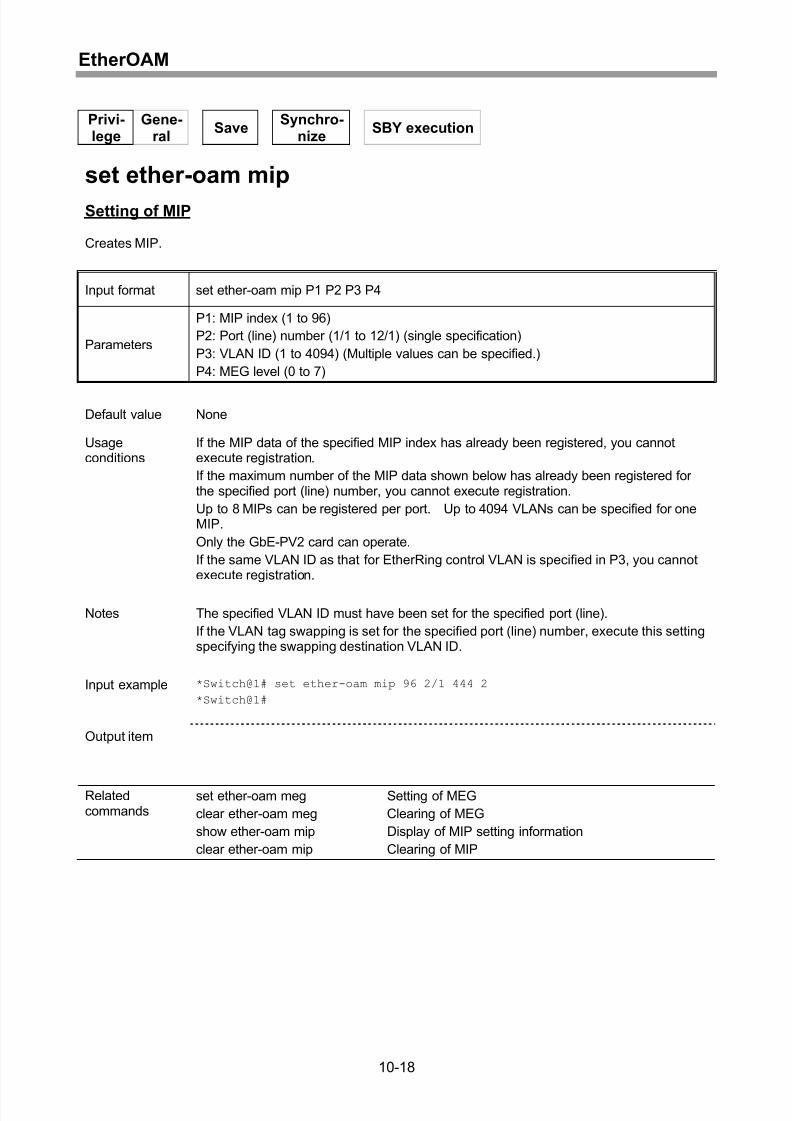
Setting of MIP.........................................................................................................10-18
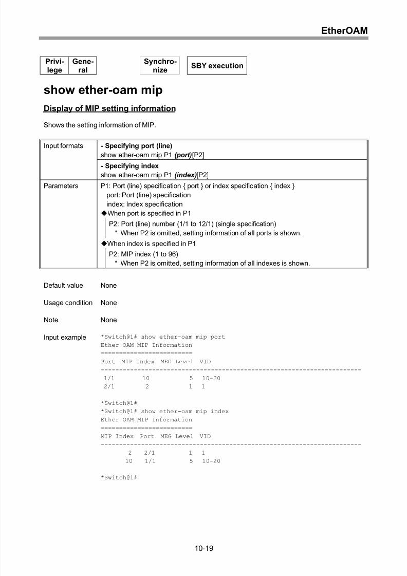
Display of MIP setting information..........................................................................10-19
xii
Page 17
8/21/2019 CX2600-220_Command_Reference_v7.6B_eng - Copy.pdf
http://slidepdf.com/reader/full/cx2600-220commandreferencev76beng-copypdf 17/758
Contents
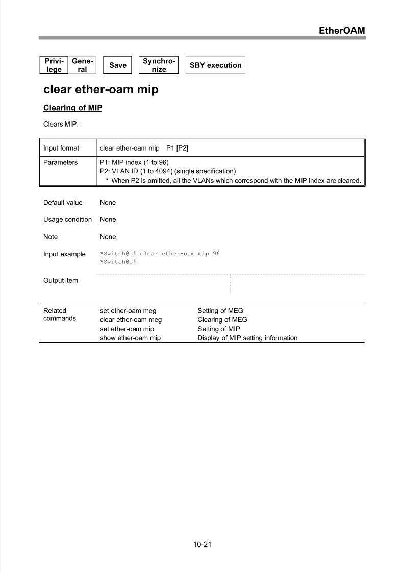
Clearing of MIP ......................................................................................................10-21
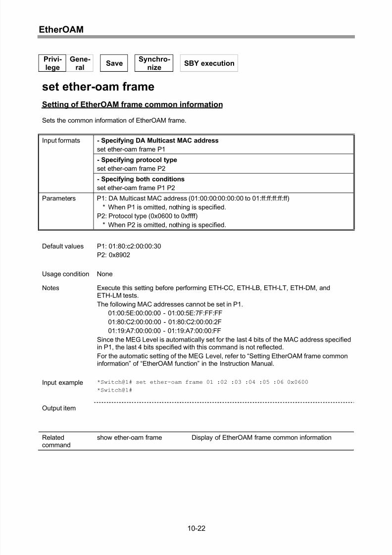
Setting of EtherOAM frame common information...................................................10-22
Display of EtherOAM frame common information ..................................................10-23
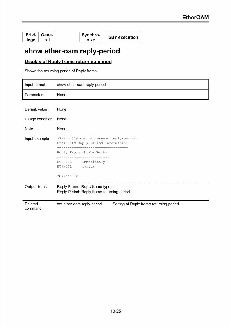
Setting of Reply frame returning period..................................................................10-24
Display of Reply frame returning period .................................................................10-25
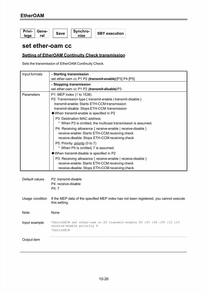
Setting of EtherOAM Continuity Check transmission .............................................10-26
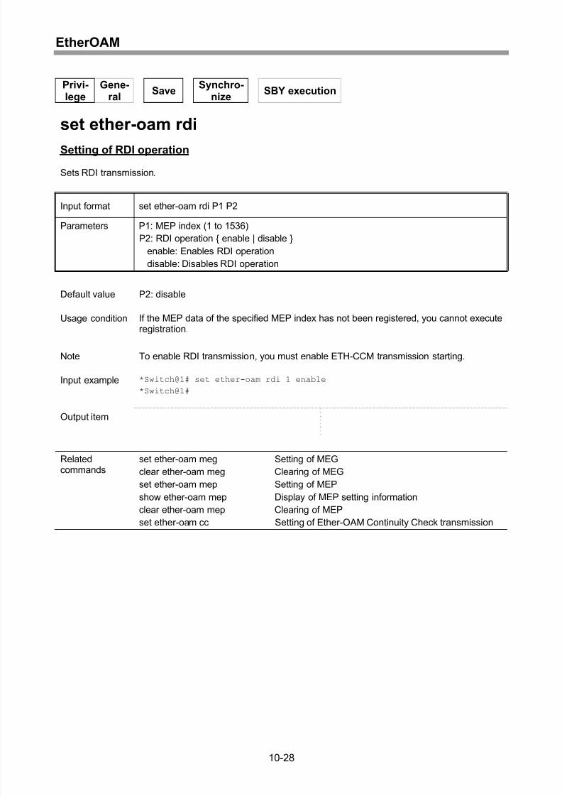
Setting of RDI operation.........................................................................................10-28
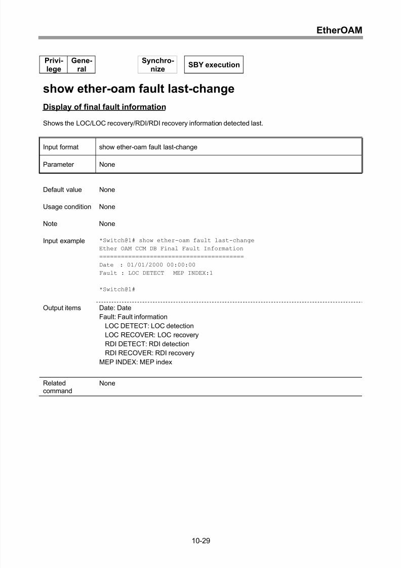
Display of final fault information .............................................................................10-29
Display of CCM error cause ...................................................................................10-30
Clearing of CCM error cause..................................................................................10-32
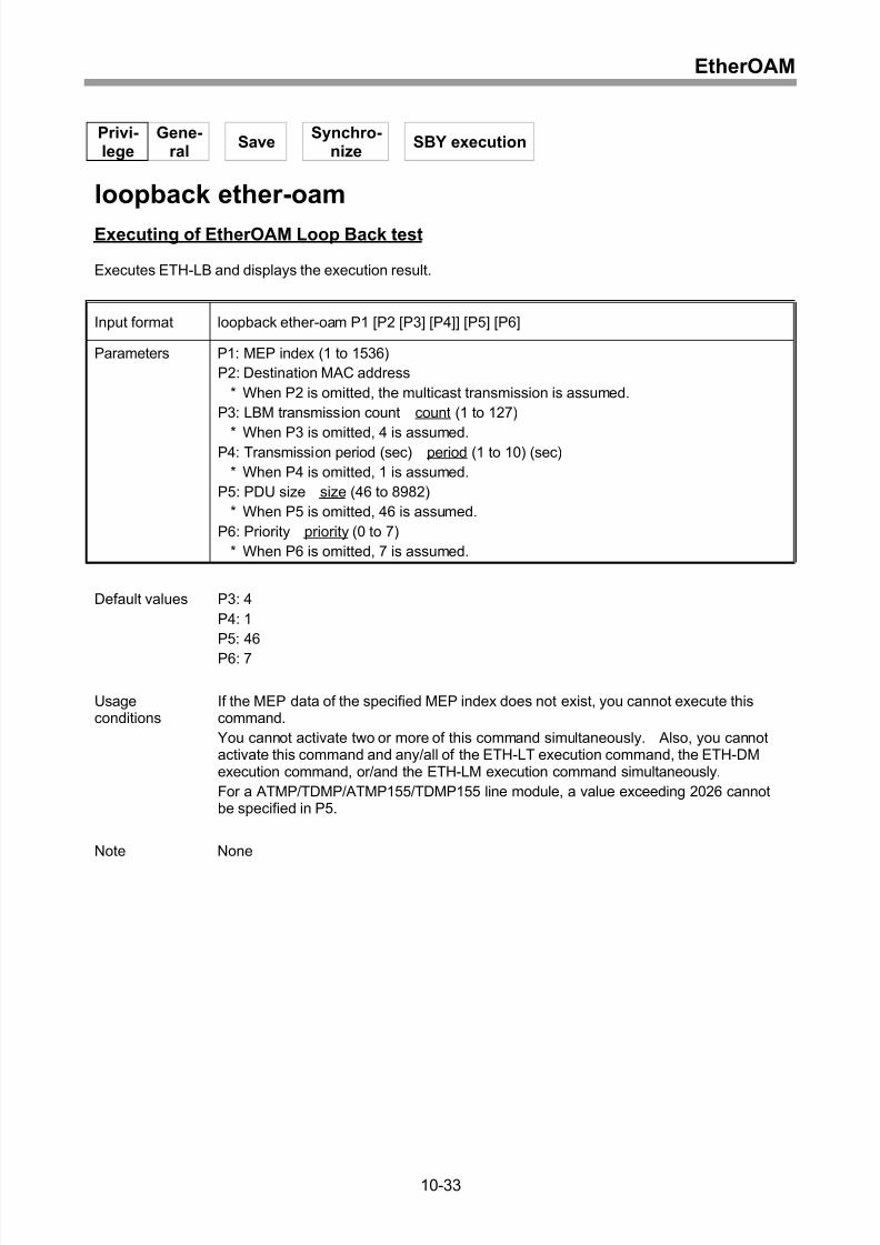
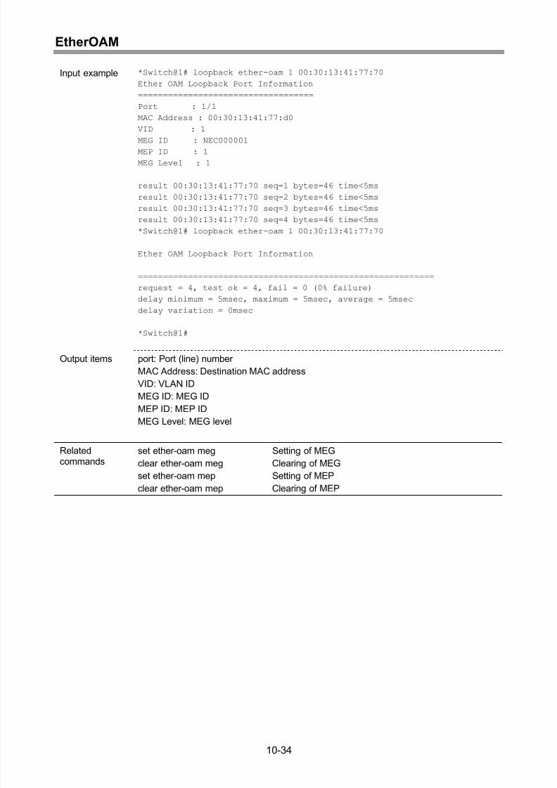
Executing of EtherOAM Loop Back test .................................................................10-33
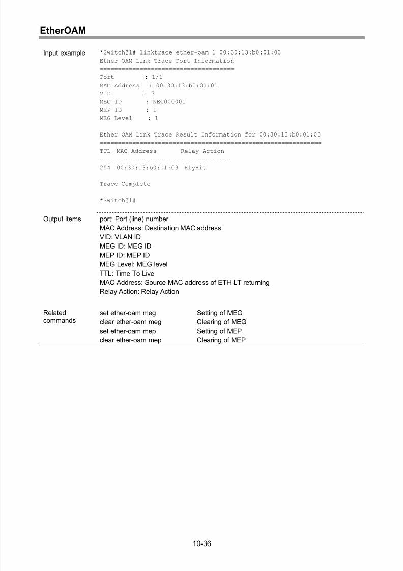
Executing of EtherOAM Link Trace test .................................................................10-35
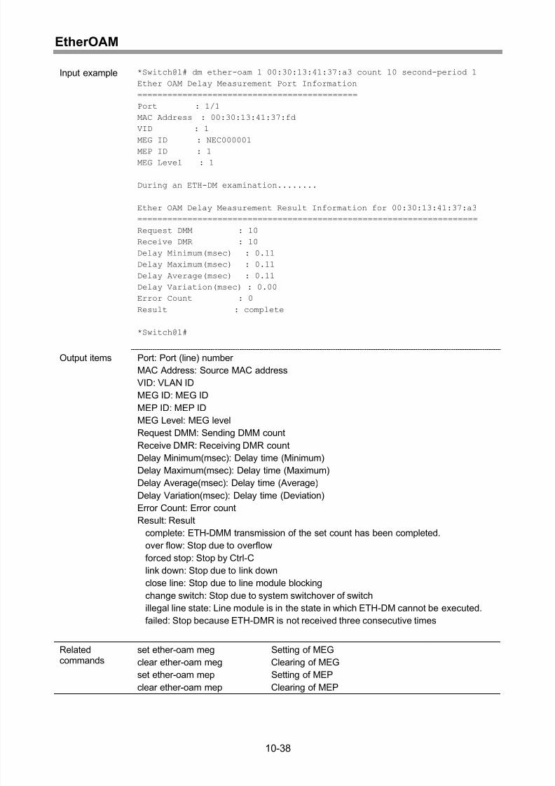
Executing of EtherOAM Frame Delay Measurement test.......................................10-37
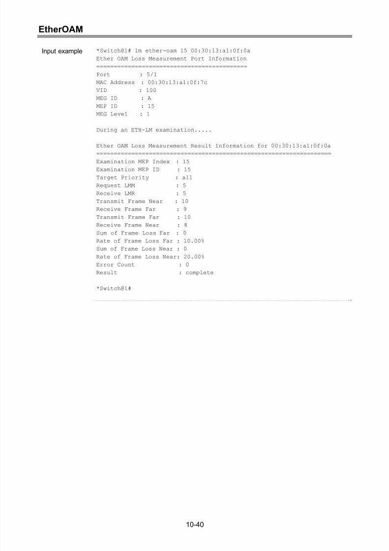
Executing of EtherOAM Frame Loss Measurement test ........................................10-39
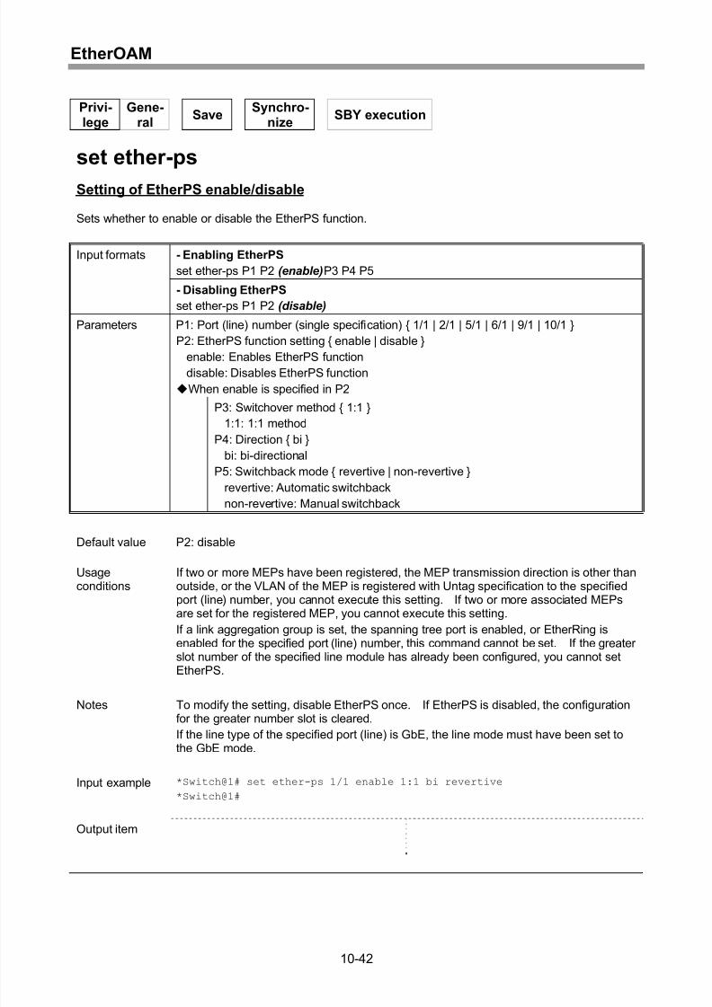
Setting of EtherPS enable/disable..........................................................................10-42
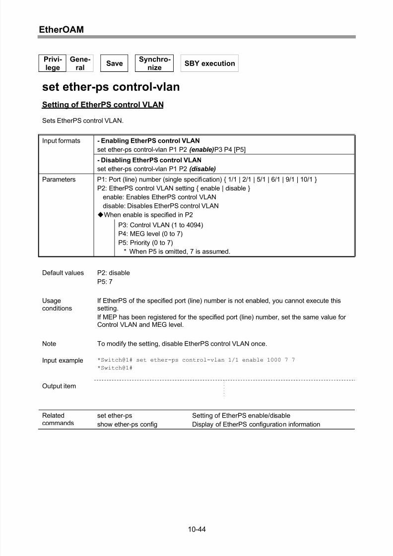
Setting of EtherPS control VLAN............................................................................10-44
Setting of EtherPS lockout .....................................................................................10-45
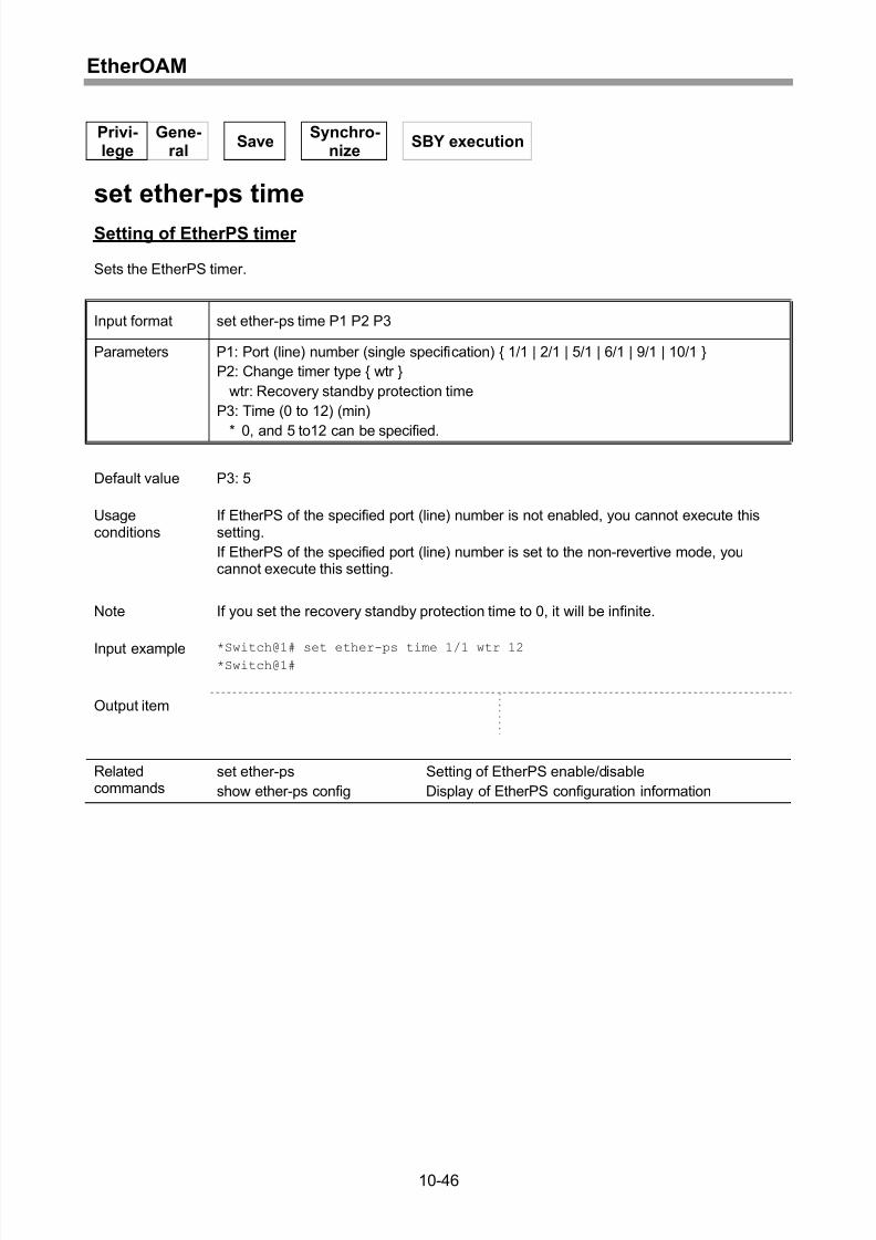
Setting of EtherPS timer.........................................................................................10-46
Changeover of EtherPS state.................................................................................10-47
Resetting of EtherPS state changeover .................................................................10-48
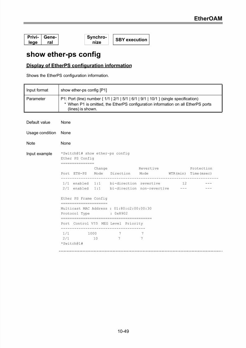
Display of EtherPS configuration information .........................................................10-49
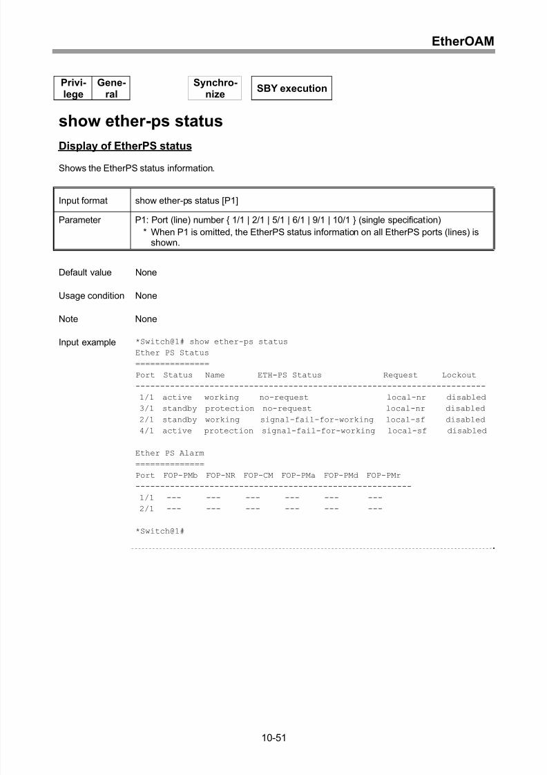
Display of EtherPS status.......................................................................................10-51
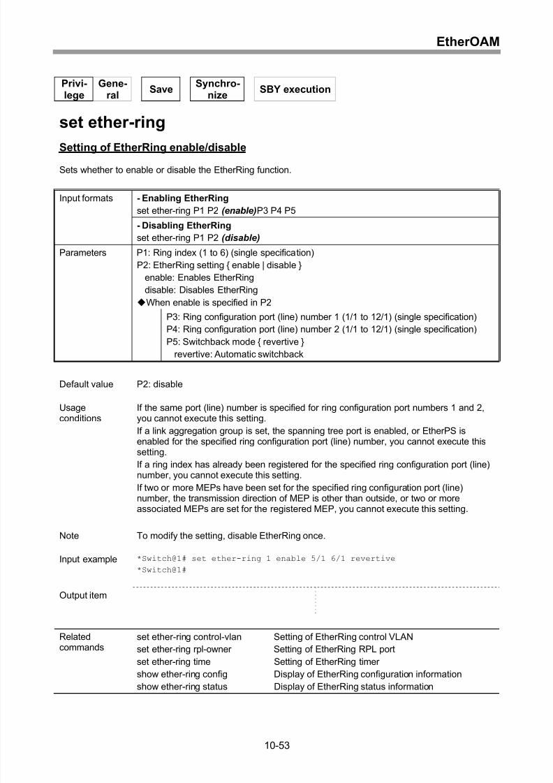
Setting of EtherRing enable/disable .......................................................................10-53
Setting of EtherRing control VLAN .........................................................................10-54
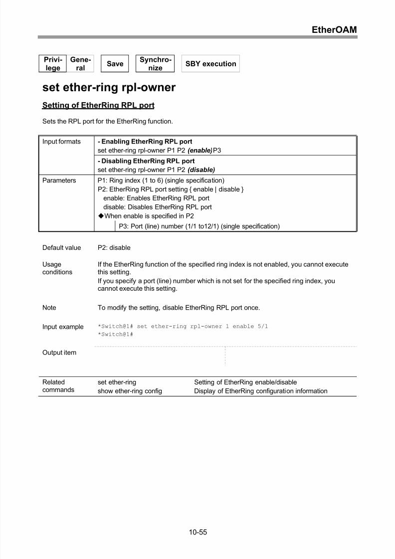
Setting of EtherRing RPL port ................................................................................10-55
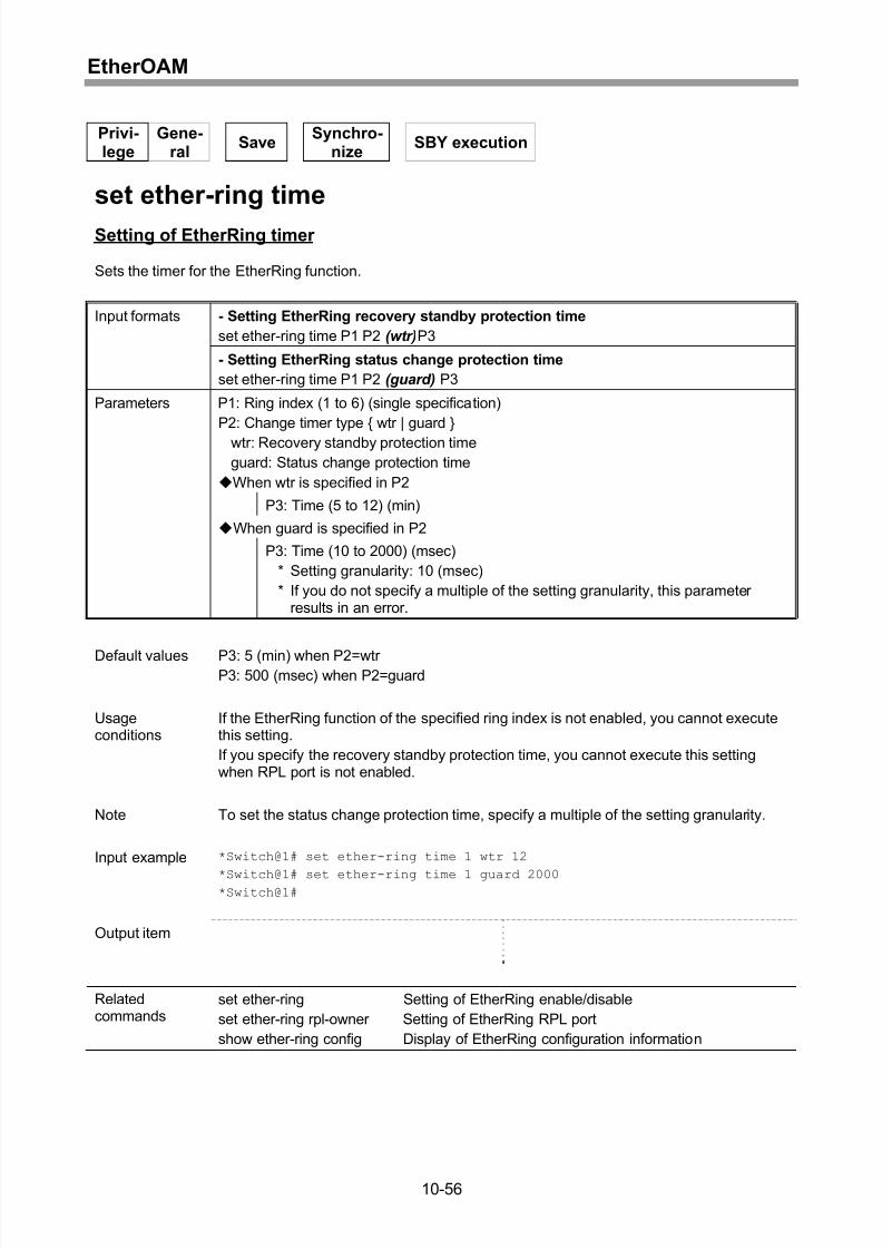
Setting of EtherRing timer ......................................................................................10-56
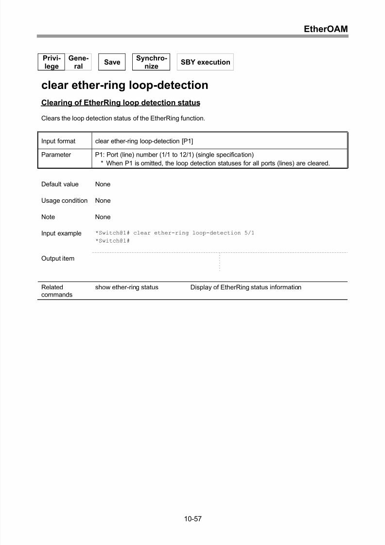
Clearing of EtherRing loop detection status ...........................................................10-57
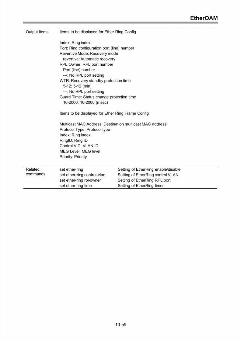
Display of EtherRing configuration information ......................................................10-58
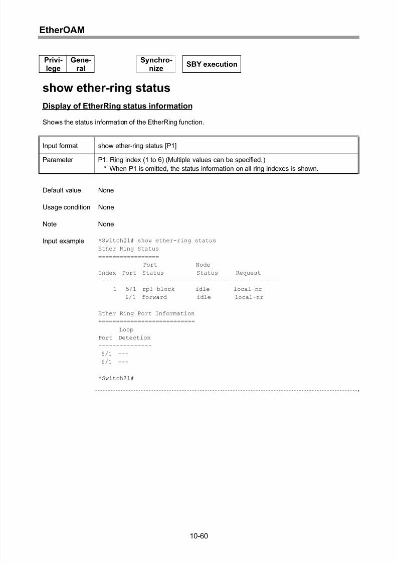
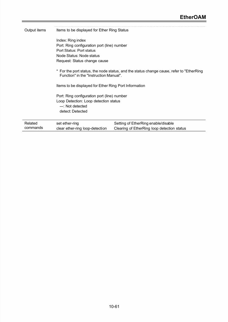
Display of EtherRing status information .................................................................10-60
11 APS ........................................................................................11-1
Setting of APS enable/disable..................................................................................11-2
Setting of APS lockout..............................................................................................11-4
Setting of APS timer values......................................................................................11-5
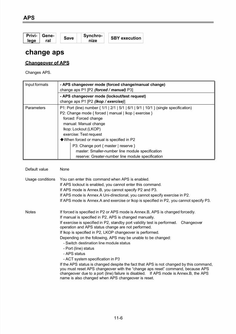
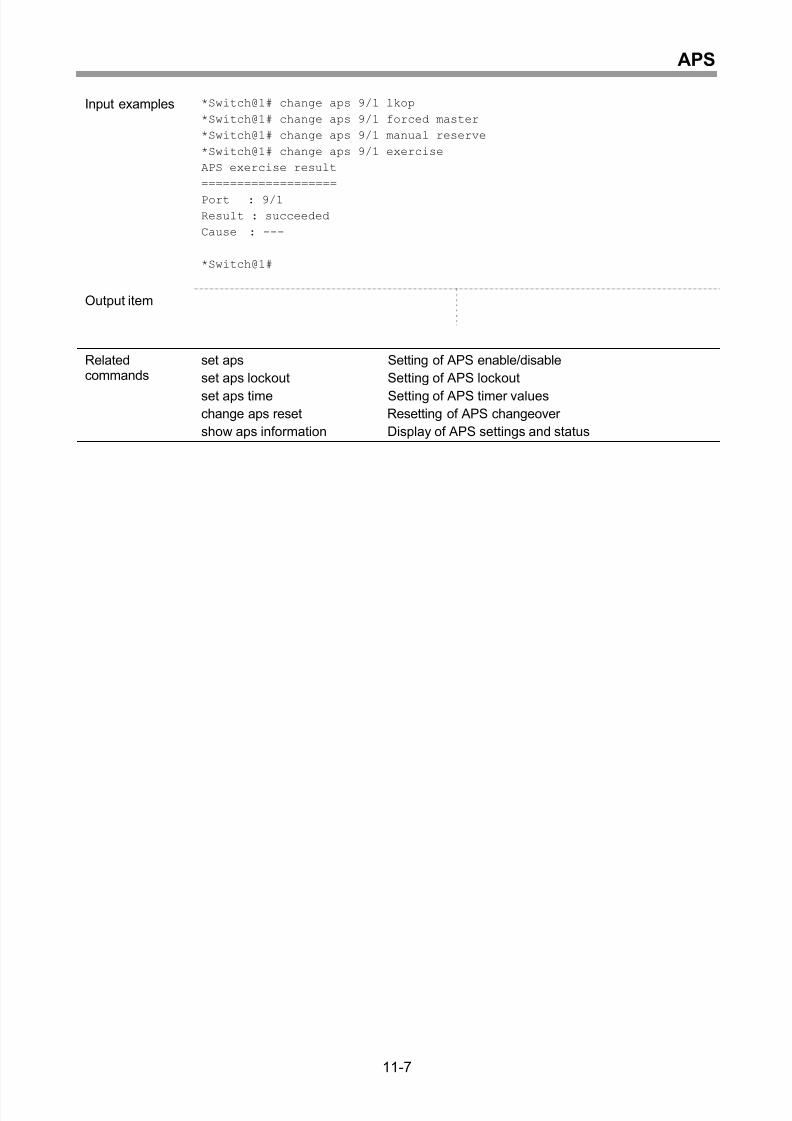
Changeover of APS..................................................................................................11-6
Resetting of APS changeover ..................................................................................11-8
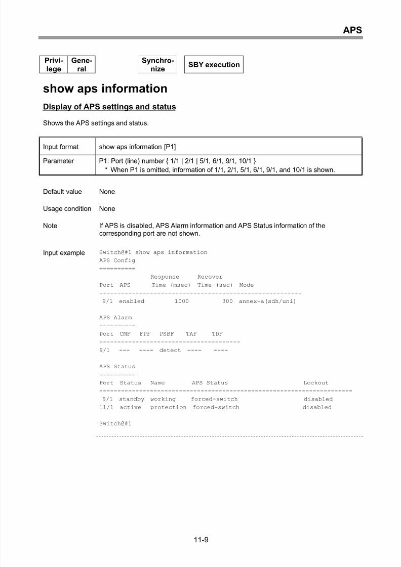
Display of APS settings and status ..........................................................................11-9
xiii
Page 18
8/21/2019 CX2600-220_Command_Reference_v7.6B_eng - Copy.pdf
http://slidepdf.com/reader/full/cx2600-220commandreferencev76beng-copypdf 18/758
Contents
12 ATM Control ..........................................................................12-1
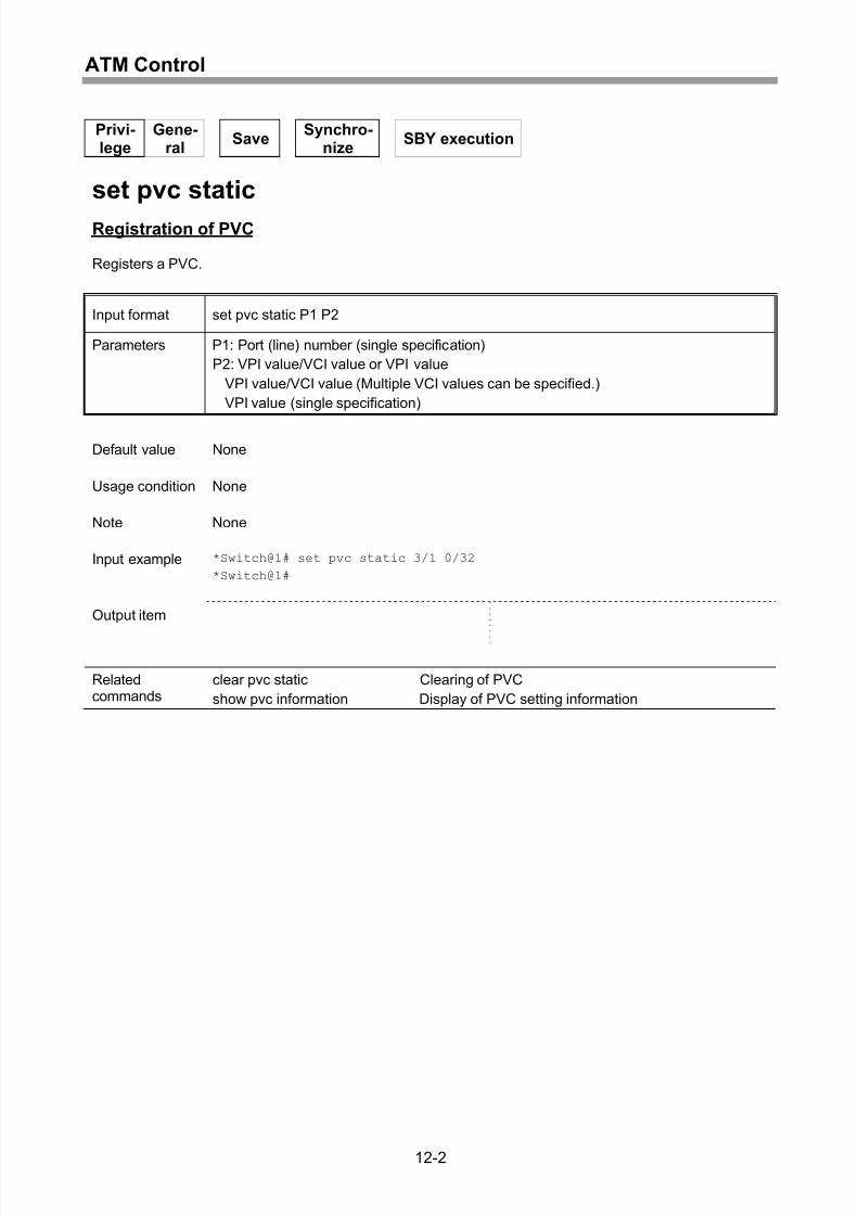
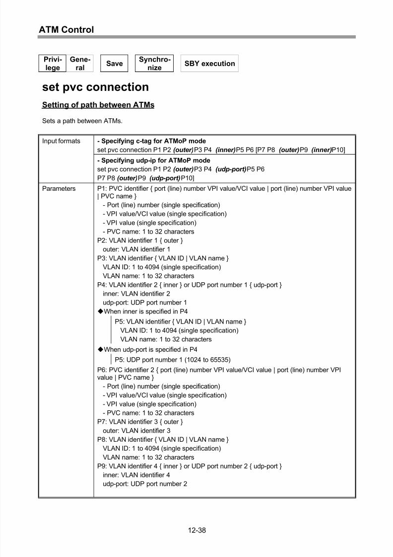
Registration of PVC..................................................................................................12-2
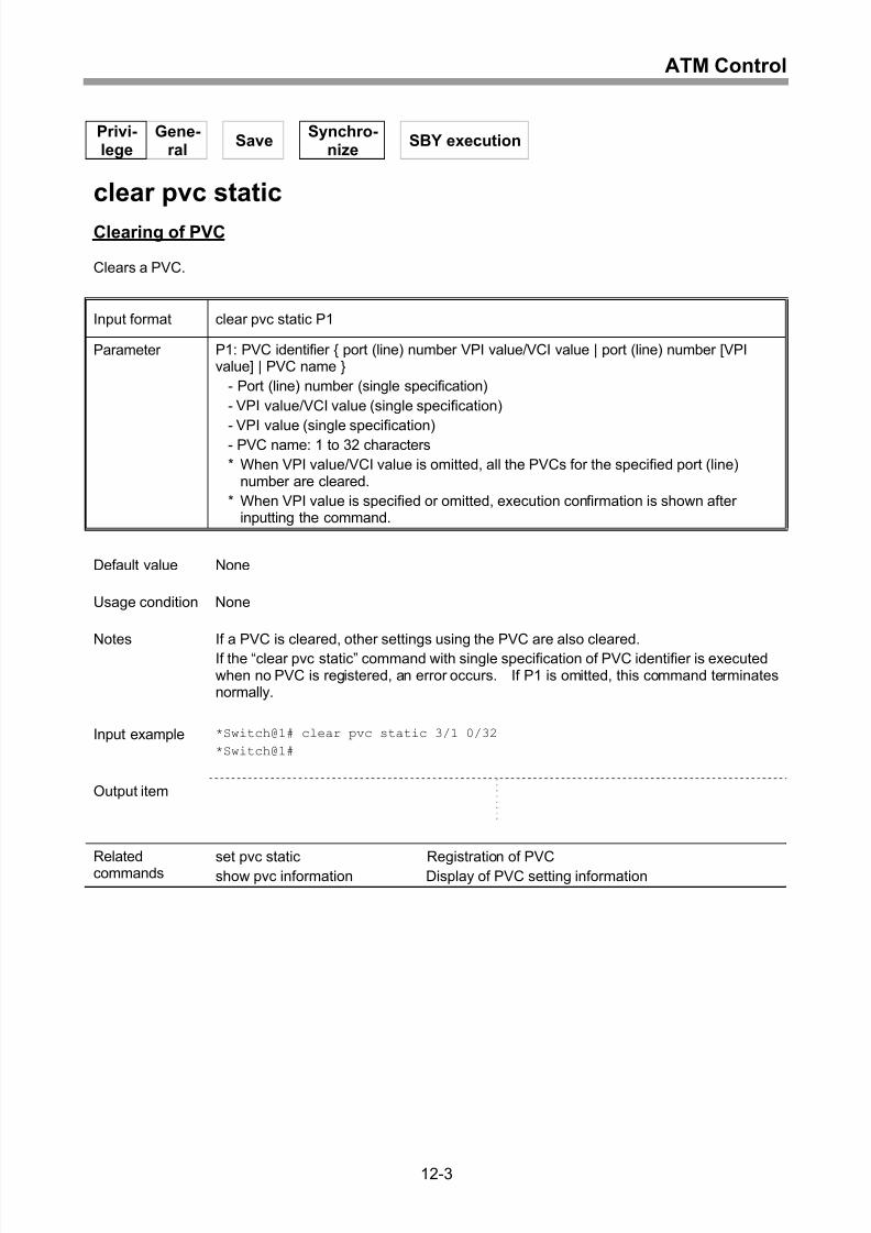
Clearing of PVC .......................................................................................................12-3
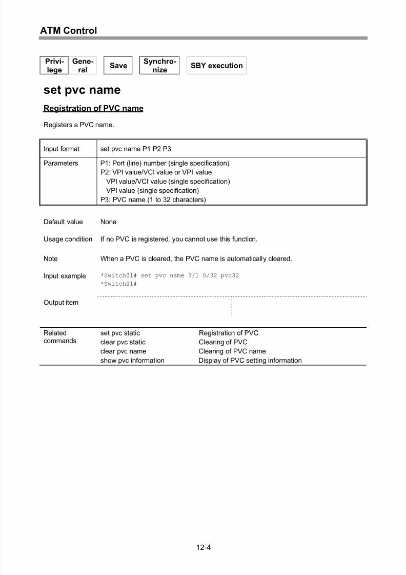
Registration of PVC name........................................................................................12-4
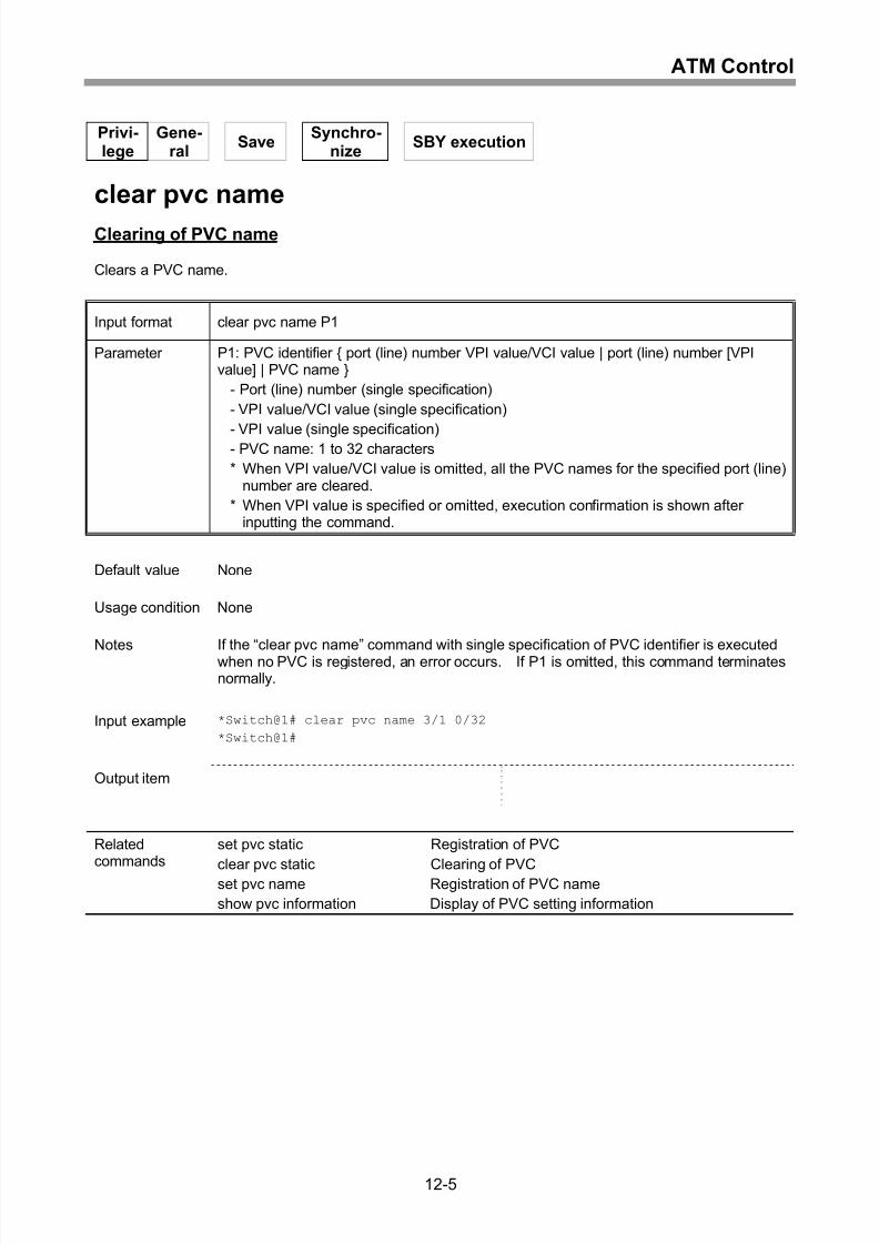
Clearing of PVC name..............................................................................................12-5
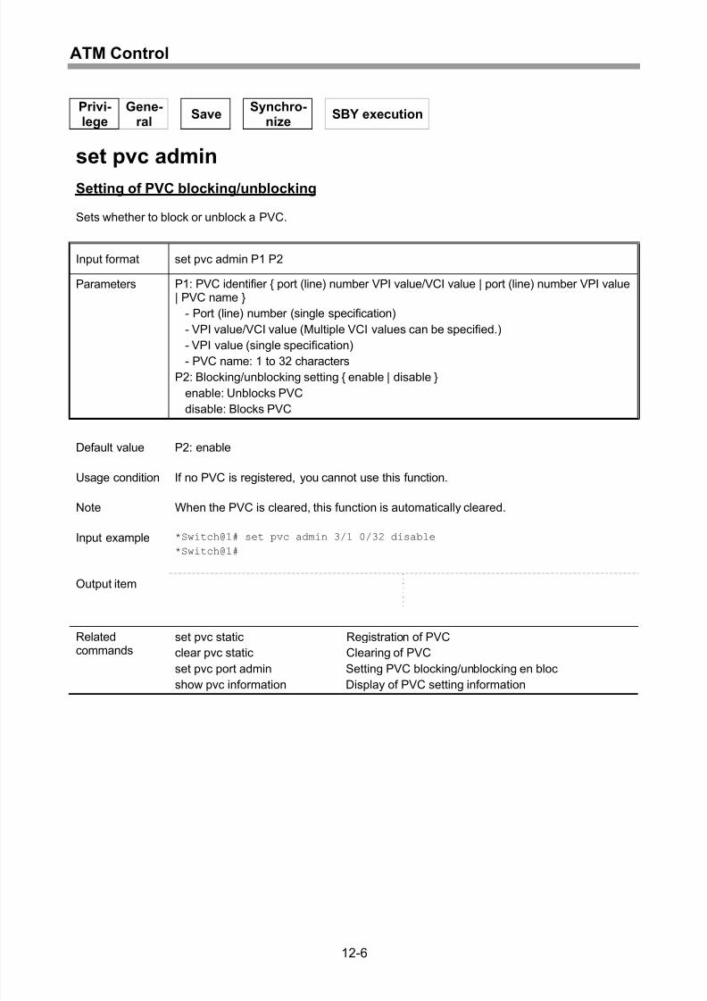
Setting of PVC blocking/unblocking .........................................................................12-6
Setting PVC blocking/unblocking en bloc .................................................................12-7
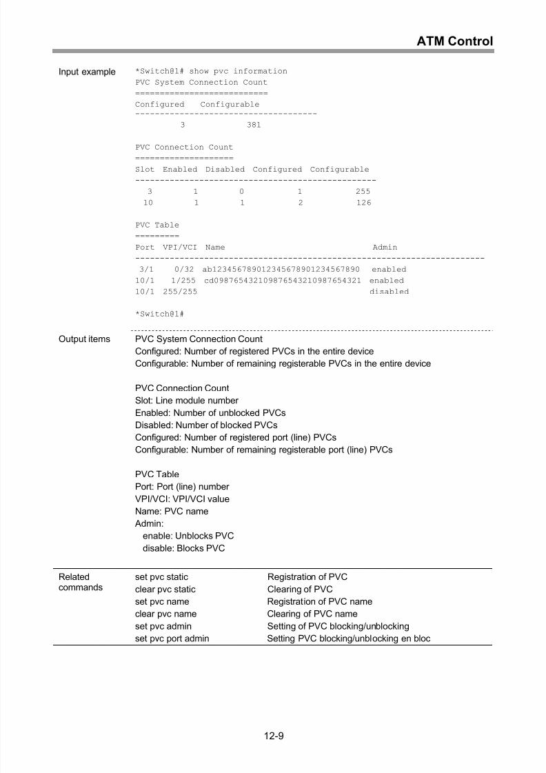
Display of PVC setting information...........................................................................12-8
Setting of PVC-VLAN mode ...................................................................................12-10
Setting of VLAN VC................................................................................................12-11
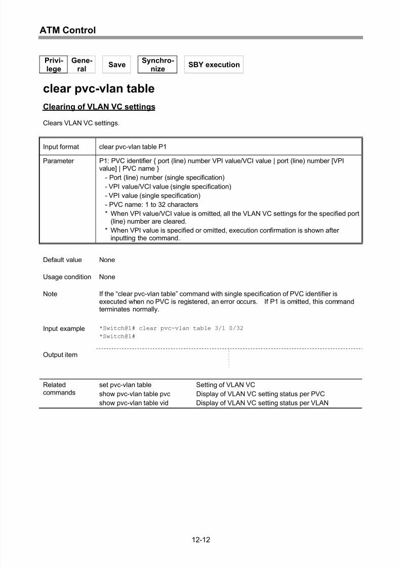
Clearing of VLAN VC settings ................................................................................12-12
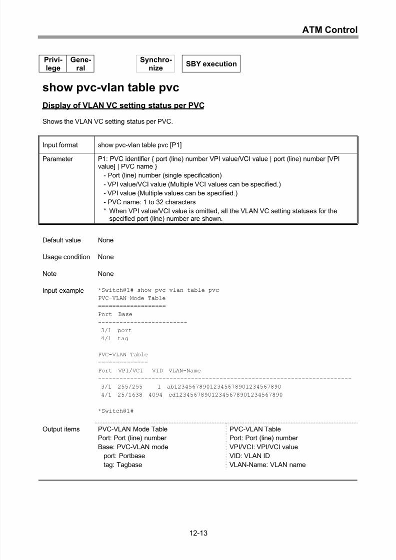
Display of VLAN VC setting status per PVC...........................................................12-13
Display of VLAN VC setting status per VLAN.........................................................12-15
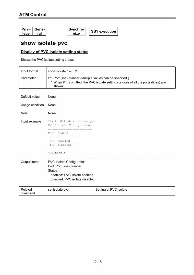
Setting/clearing of PVC isolate...............................................................................12-17
Display of PVC isolate setting status......................................................................12-18
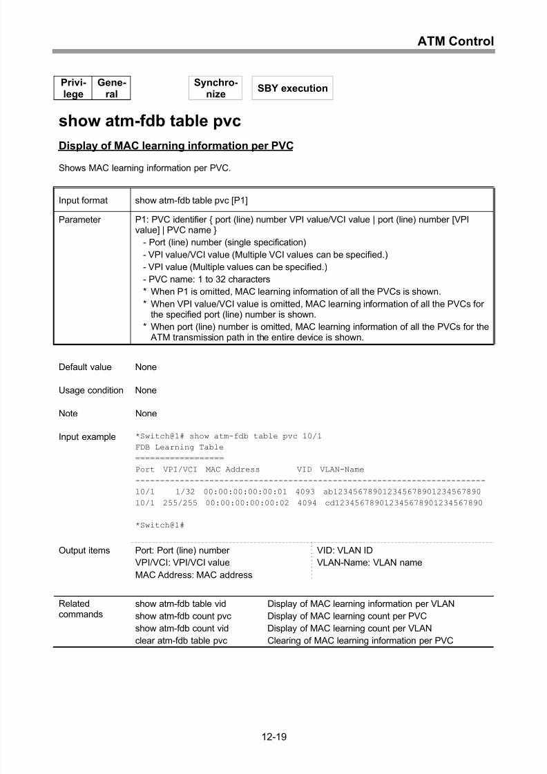
Display of MAC learning information per PVC........................................................12-19
Display of MAC learning information per VLAN......................................................12-20
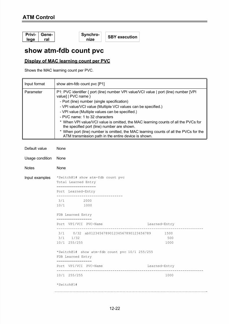
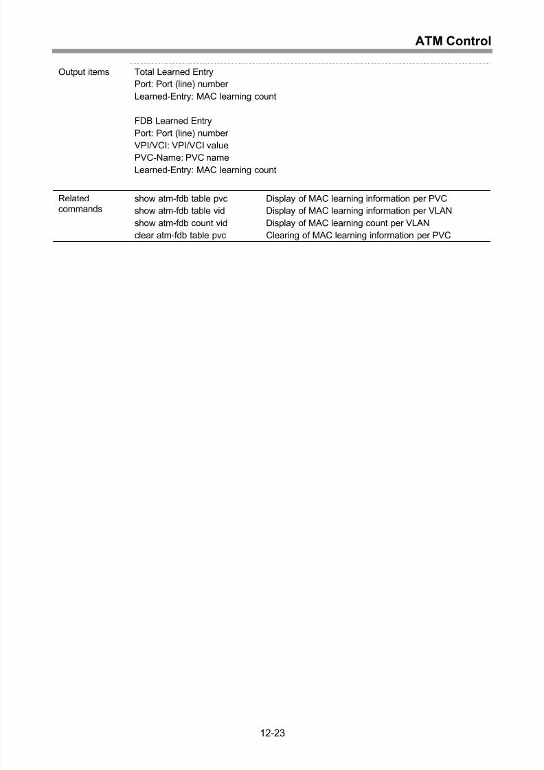
Display of MAC learning count per PVC.................................................................12-22
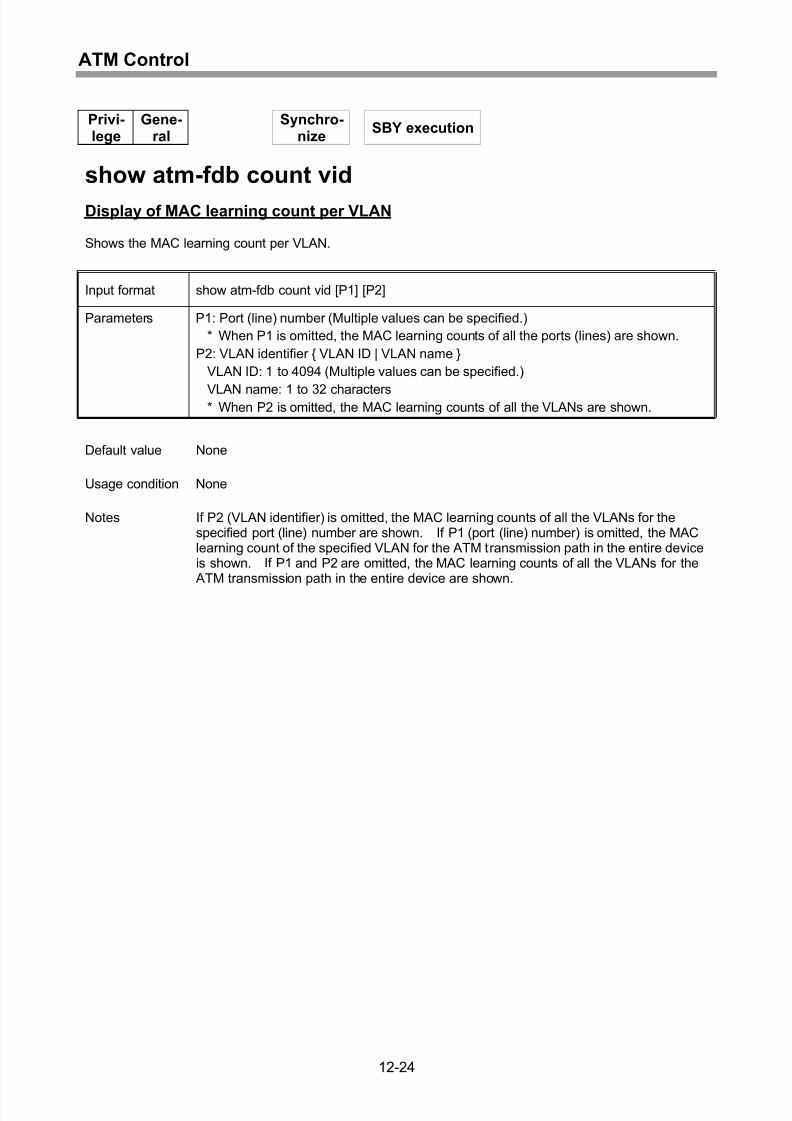
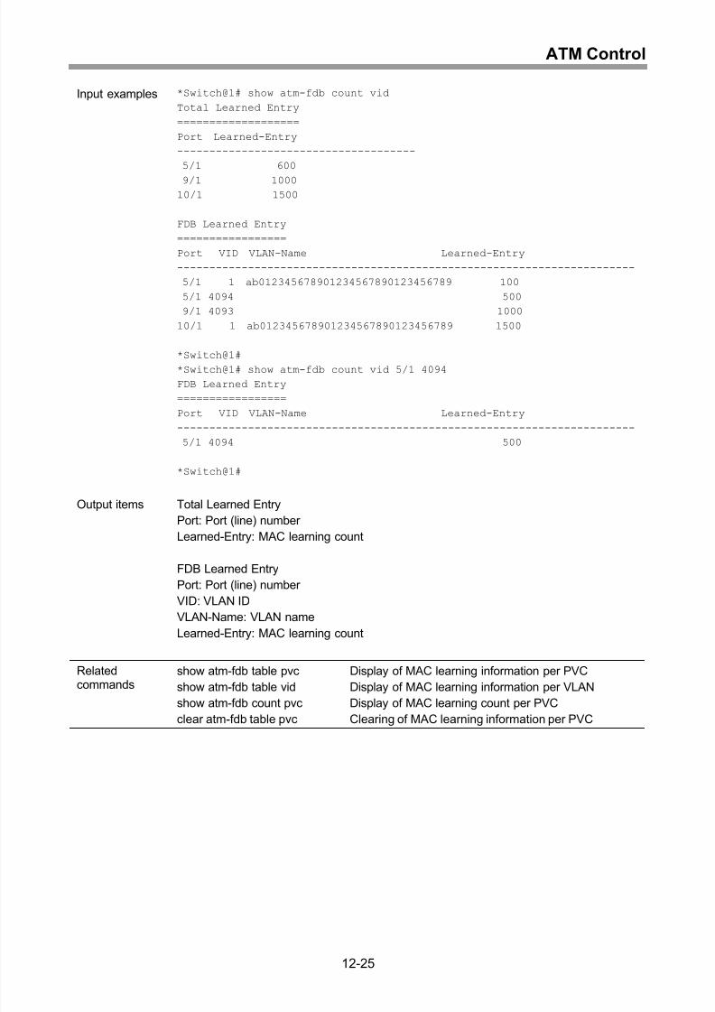
Display of MAC learning count per VLAN...............................................................12-24
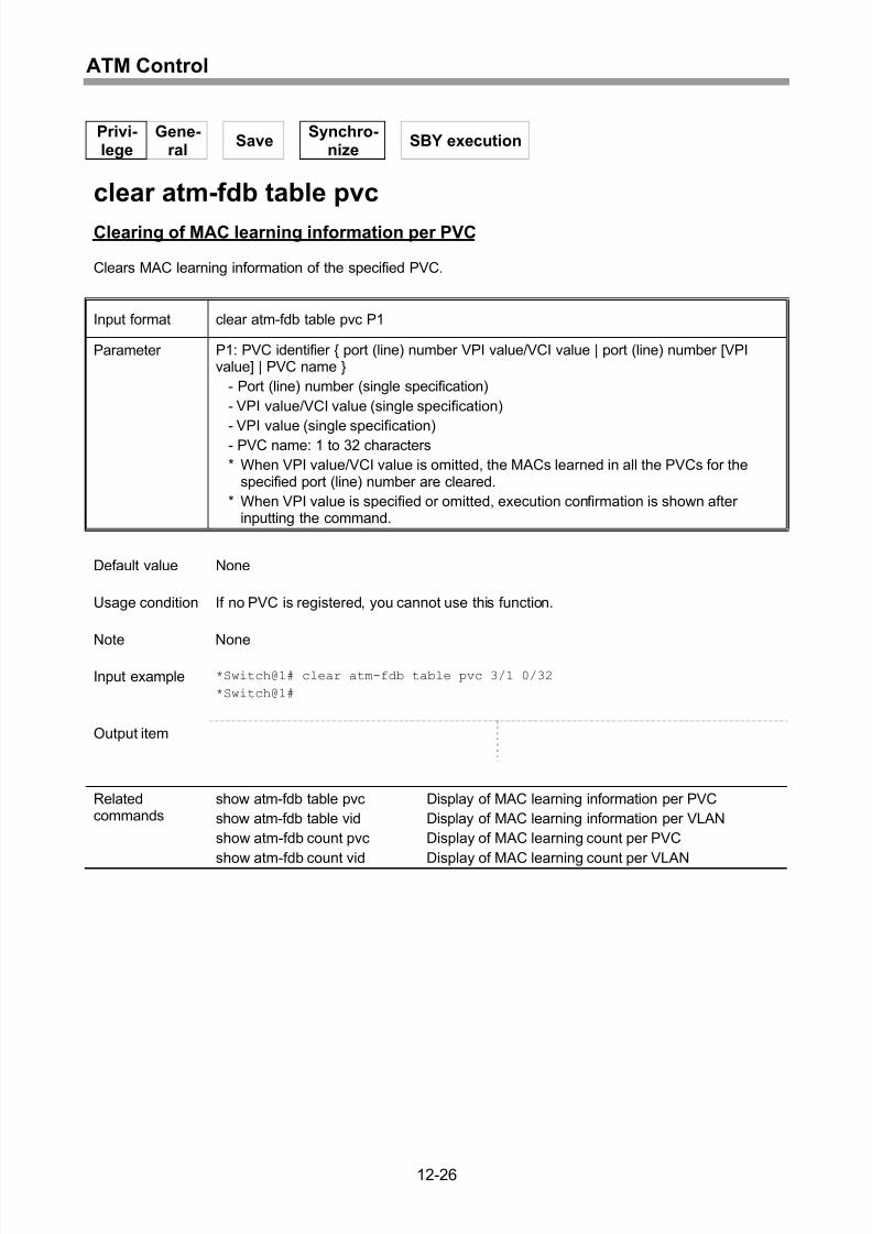
Clearing of MAC learning information per PVC......................................................12-26
Setting/clearing of ATM loop guard ........................................................................12-27
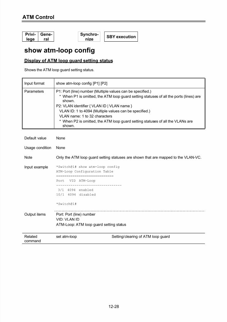
Display of ATM loop guard setting status...............................................................12-28
Display of ATM loop trap transmission state ..........................................................12-29
Clearing of ATM loop detection ..............................................................................12-30
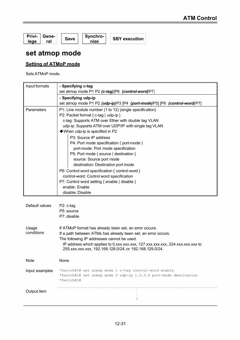
Setting of ATMoP mode .........................................................................................12-31
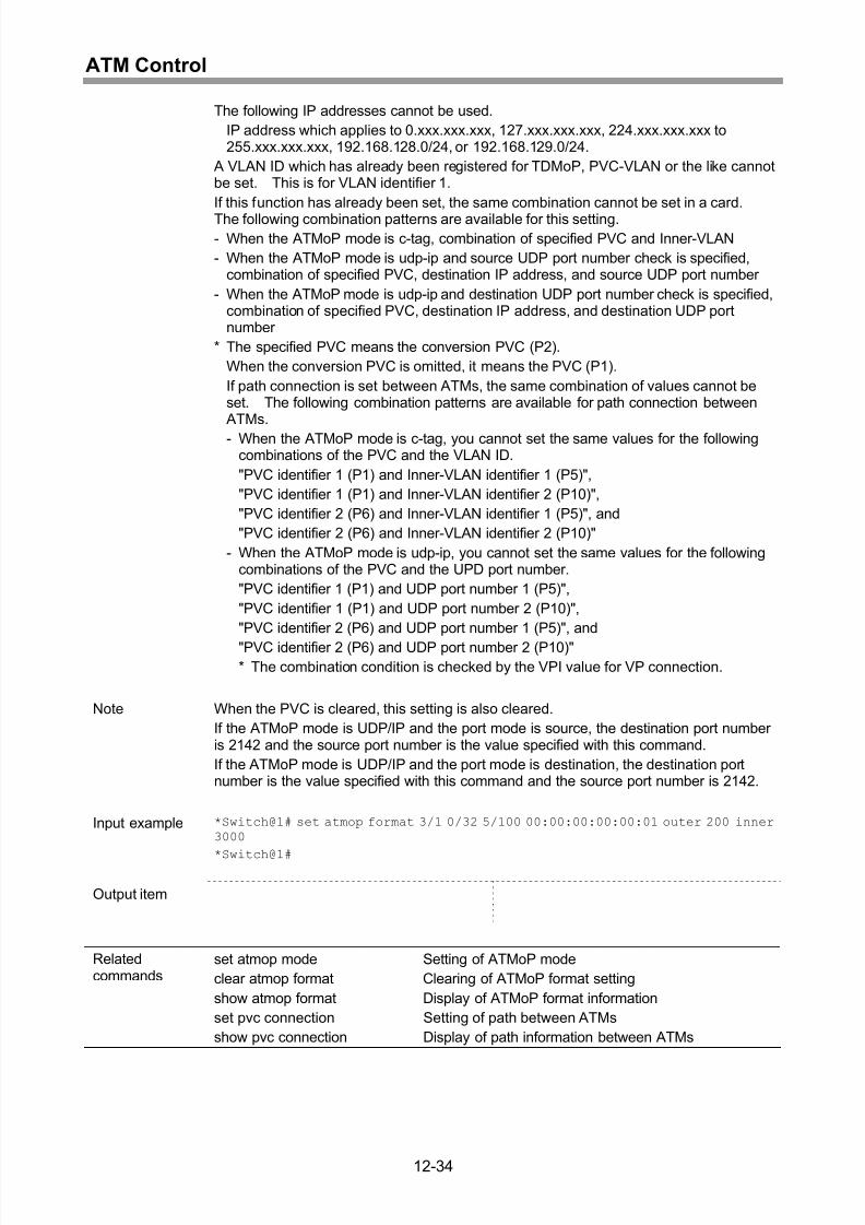
Setting of ATMoP format ........................................................................................12-33
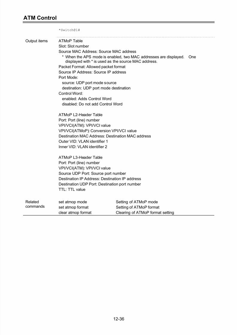
Display of ATMoP format information.....................................................................12-35
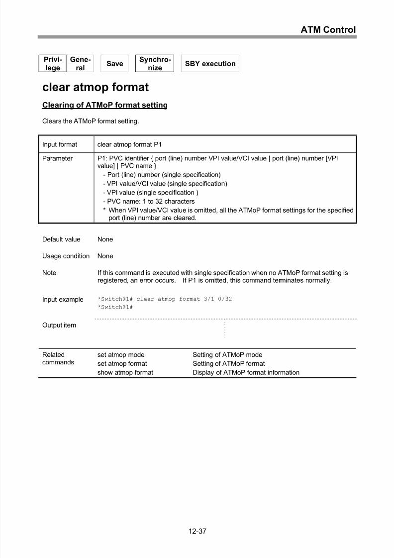
Clearing of ATMoP format setting ..........................................................................12-37
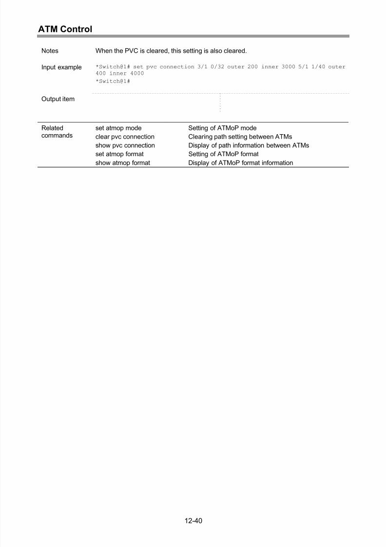
Setting of path between ATMs ...............................................................................12-38
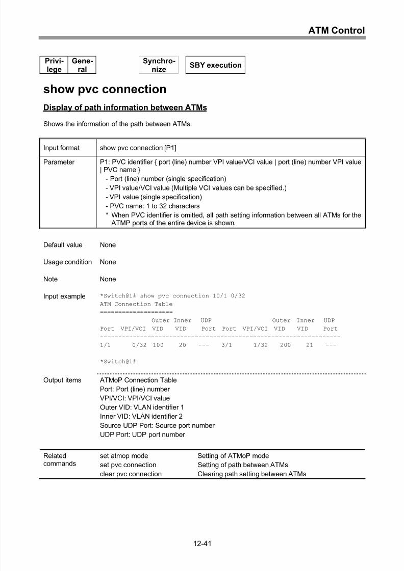
Display of path information between ATMs............................................................12-41
Clearing path setting between ATMs......................................................................12-42
13 ATM-QoS ...............................................................................13-1
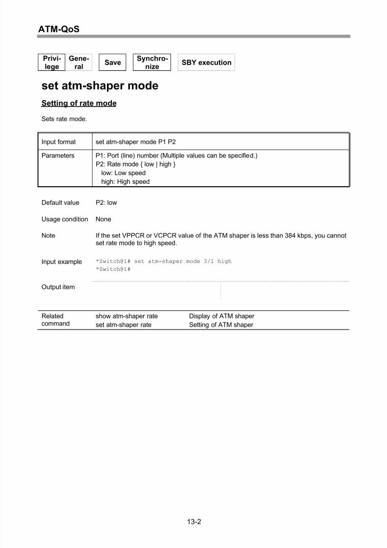
Setting of rate mode.................................................................................................13-2
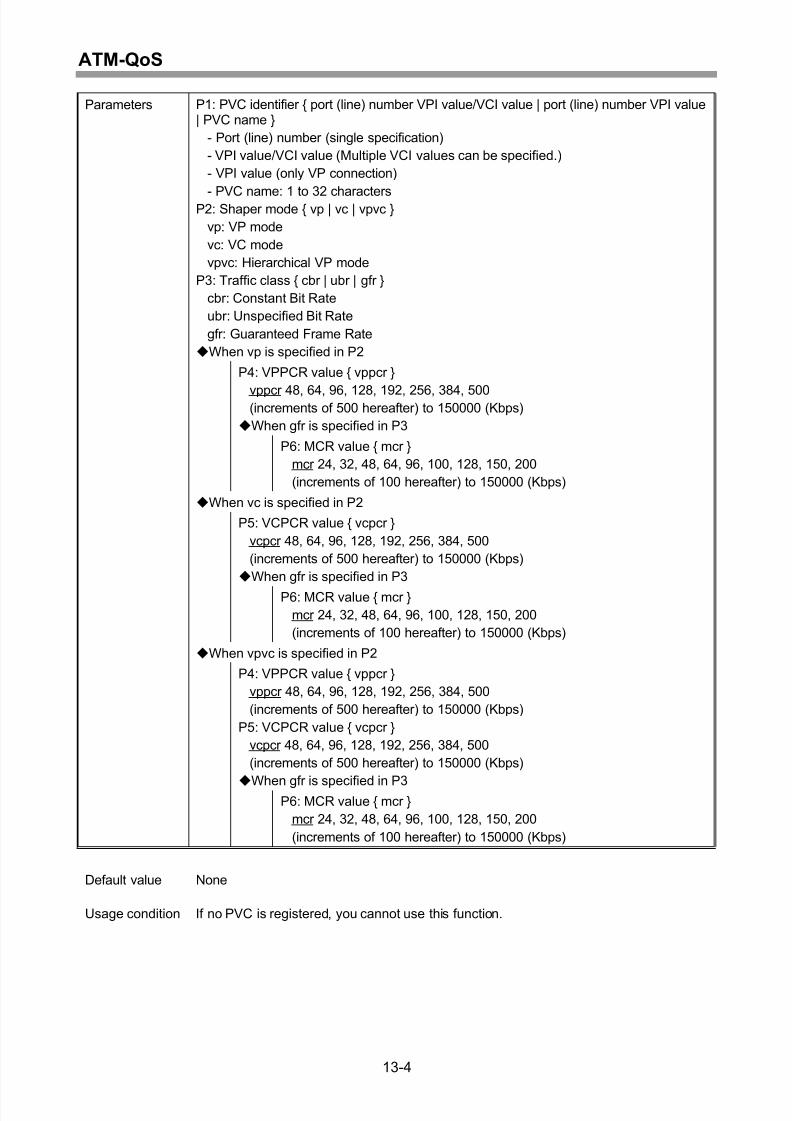
Setting of ATM shaper..............................................................................................13-3
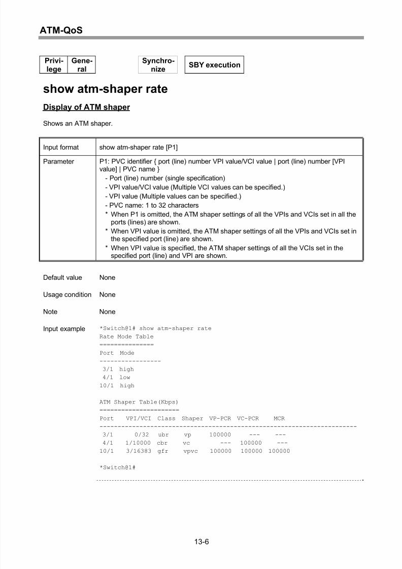
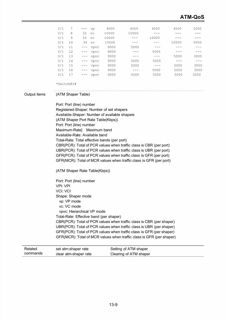
Display of ATM shaper.............................................................................................13-6
Display of effective band ..........................................................................................13-8
xiv
Page 19
8/21/2019 CX2600-220_Command_Reference_v7.6B_eng - Copy.pdf
http://slidepdf.com/reader/full/cx2600-220commandreferencev76beng-copypdf 19/758
Contents
Clearing of ATM shaper .........................................................................................13-10
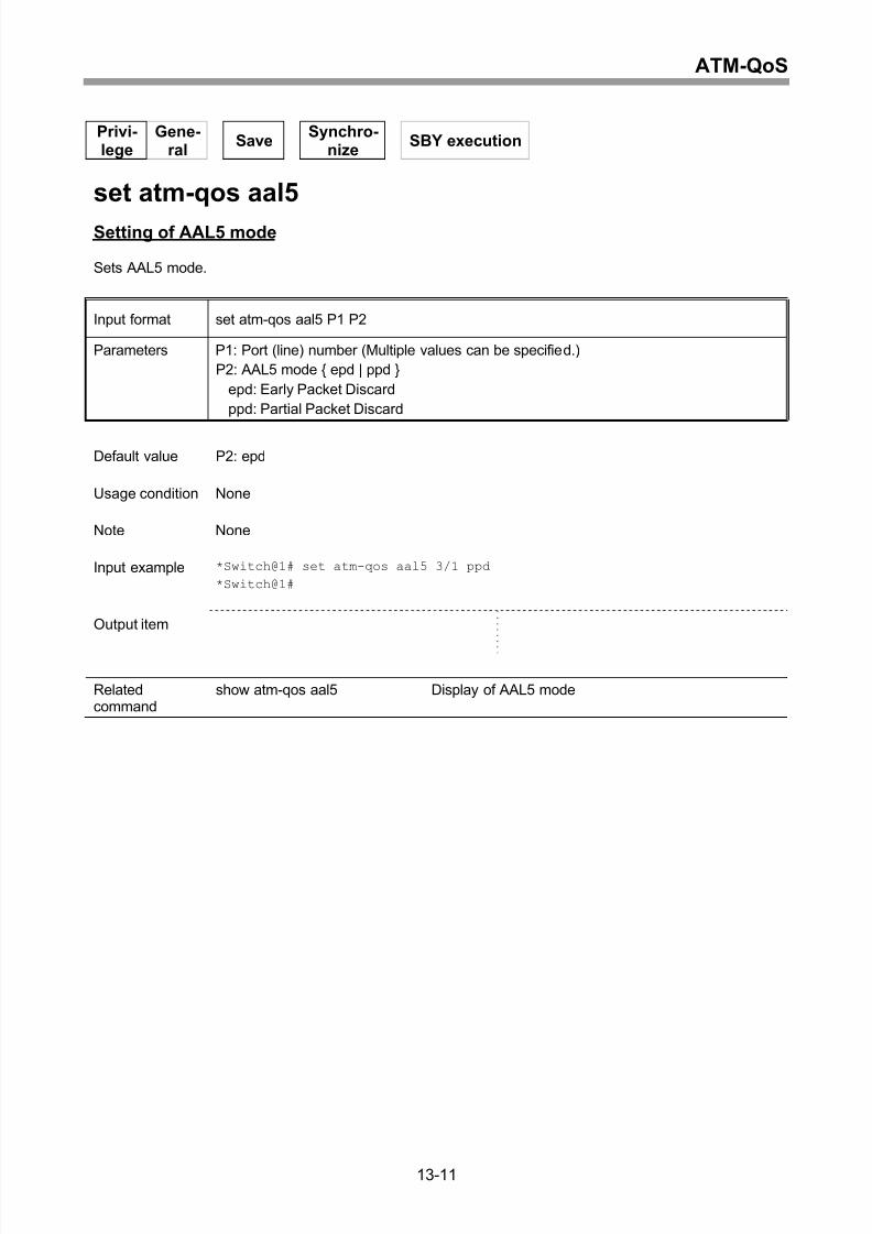
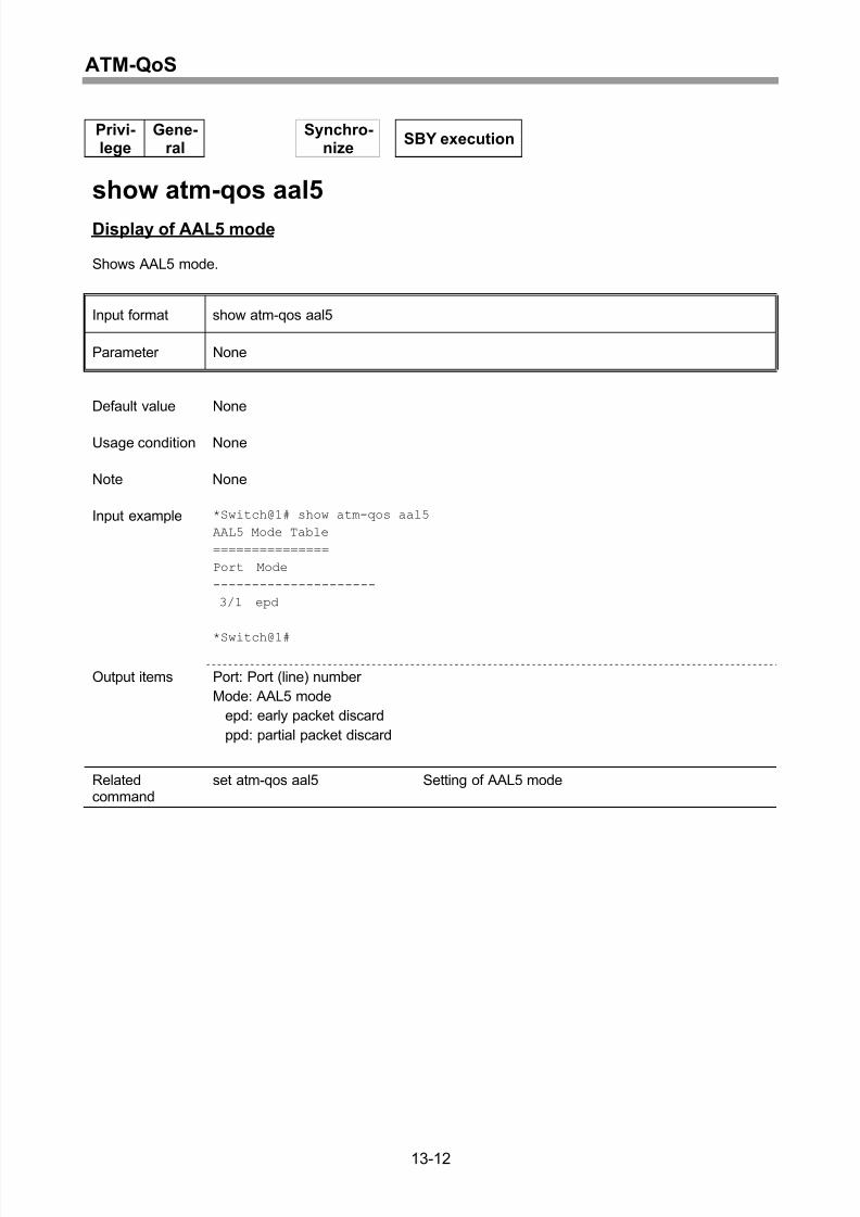
Setting of AAL5 mode ............................................................................................13-11
Display of AAL5 mode............................................................................................13-12
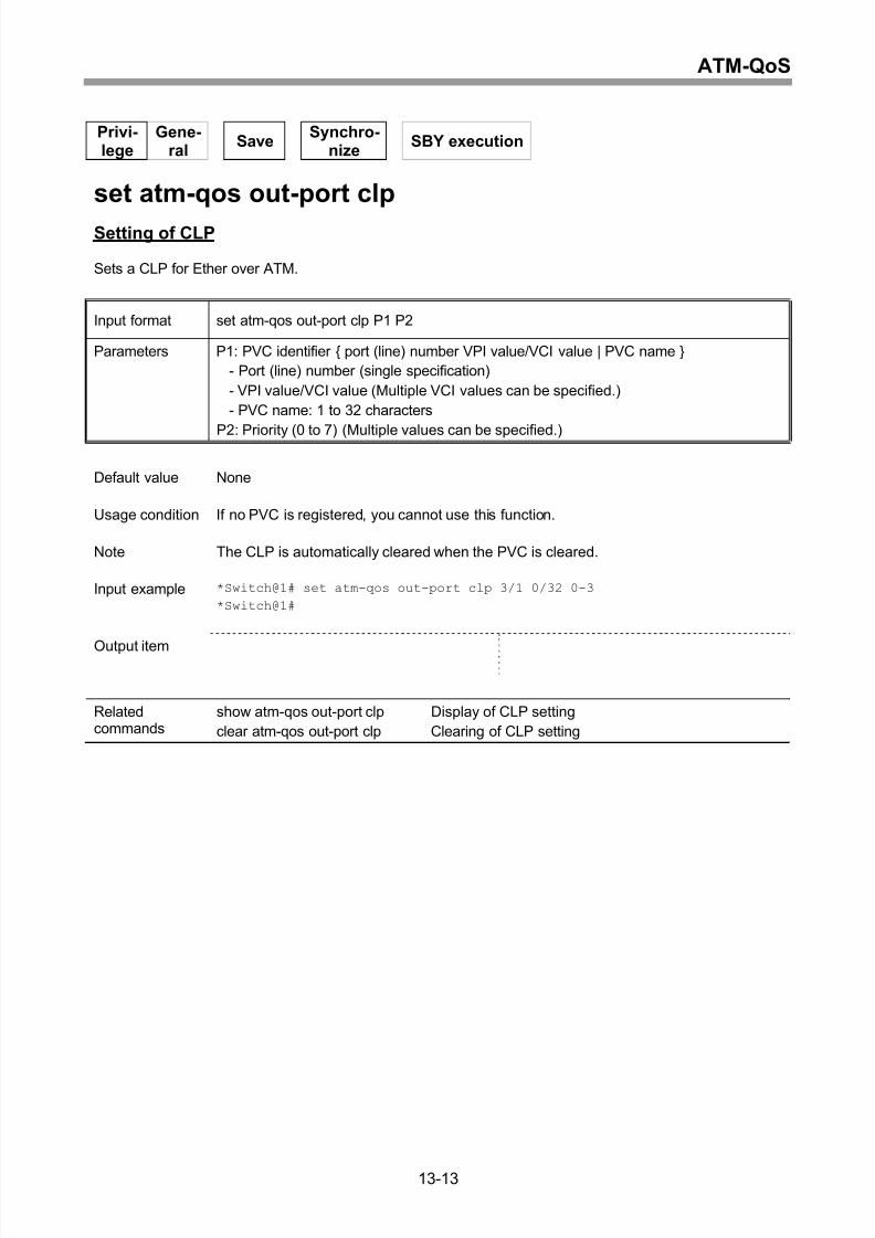
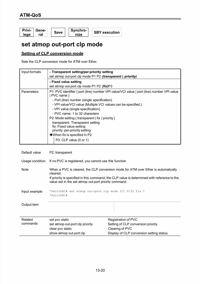
Setting of CLP........................................................................................................13-13
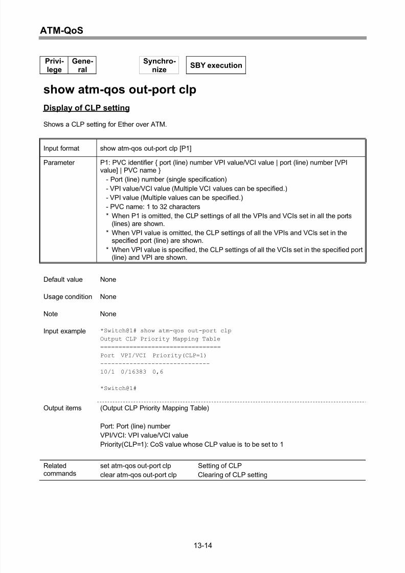
Display of CLP setting............................................................................................13-14
Clearing of CLP setting ..........................................................................................13-15
Setting of CLP-priority mapping .............................................................................13-16
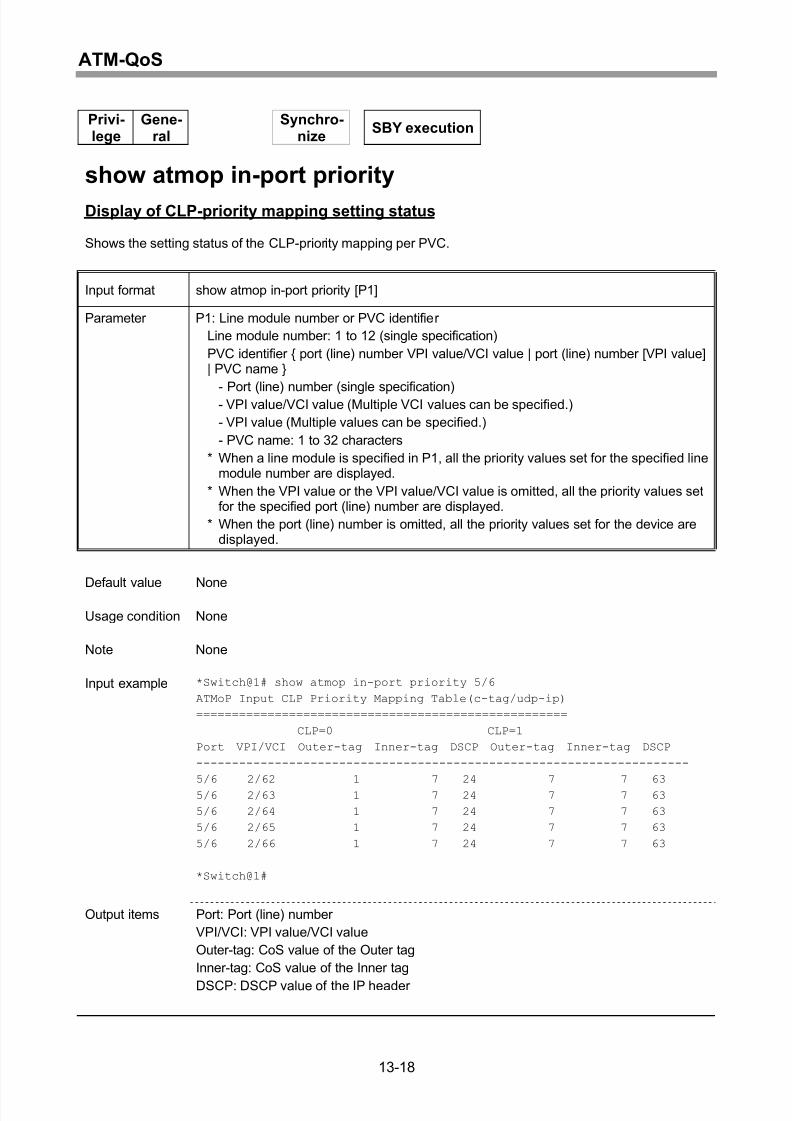
Display of CLP-priority mapping setting status.......................................................13-18
Setting of CLP conversion mode............................................................................13-20
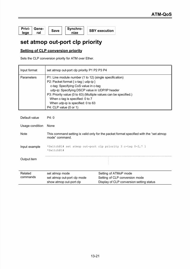
Setting of CLP conversion priority ..........................................................................13-21
Display of CLP conversion setting status ...............................................................13-22
14 ATM-OAM ..............................................................................14-1
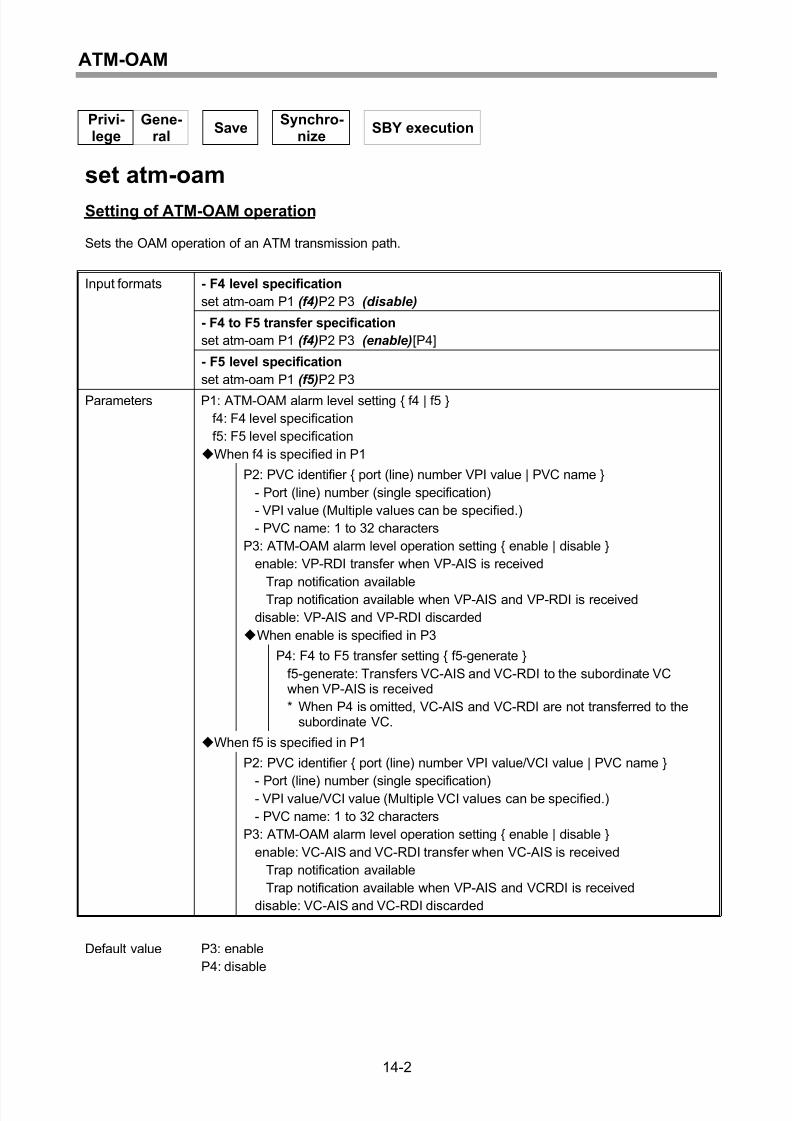
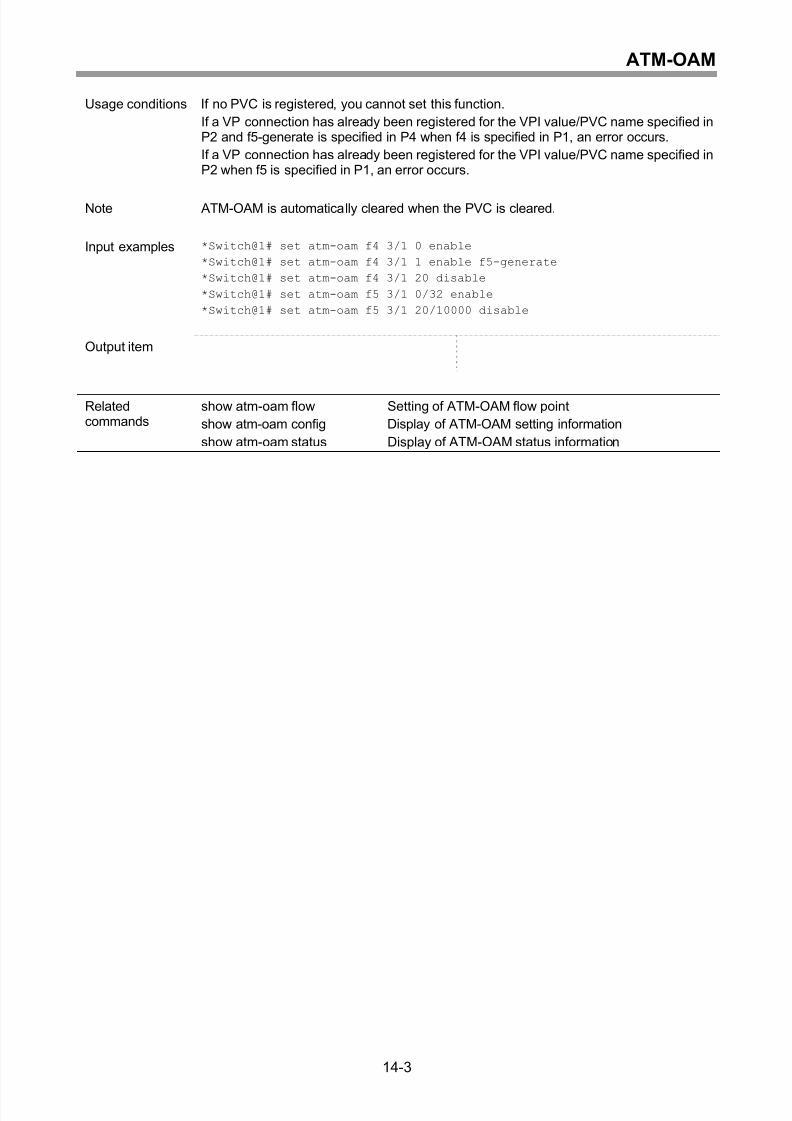
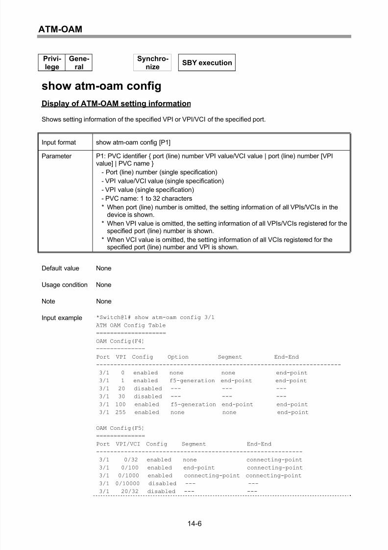
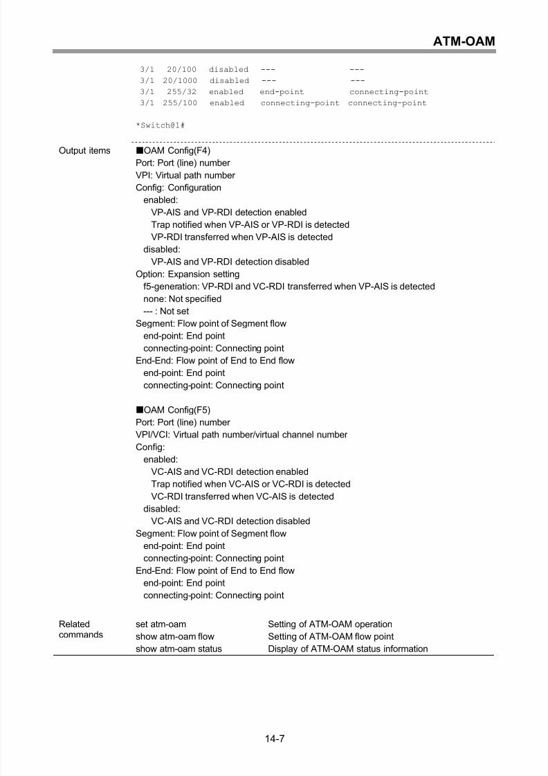
Setting of ATM-OAM operation ................................................................................14-2
Setting of ATM-OAM flow point ................................................................................14-4
Display of ATM-OAM setting information .................................................................14-6
Display of ATM-OAM status information ..................................................................14-8
15 ATM-IMA ................................................................................15-1
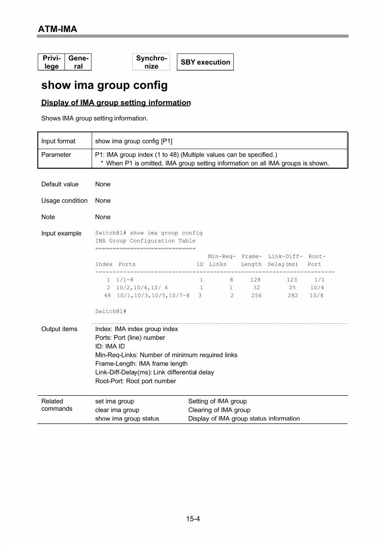
Setting of IMA group.................................................................................................15-2
Display of IMA group setting information..................................................................15-4
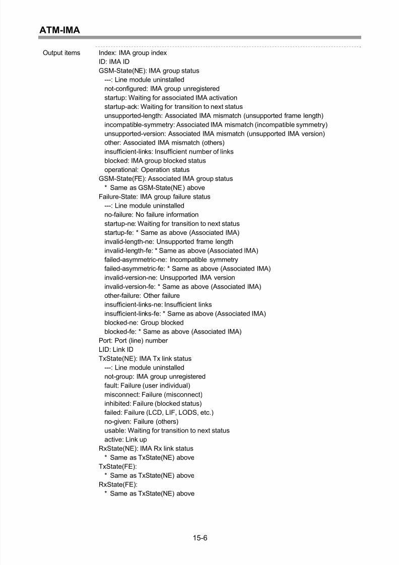
Display of IMA group status information...................................................................15-5
Clearing of IMA group ..............................................................................................15-8
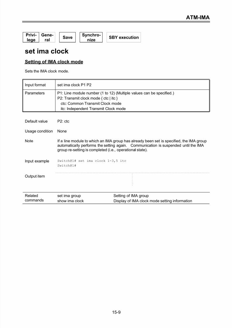
Setting of IMA clock mode........................................................................................15-9
Display of IMA clock mode setting information.......................................................15-10
Starting and result display of IMA loopback test.....................................................15-11
16 TDM-Path...............................................................................16-1
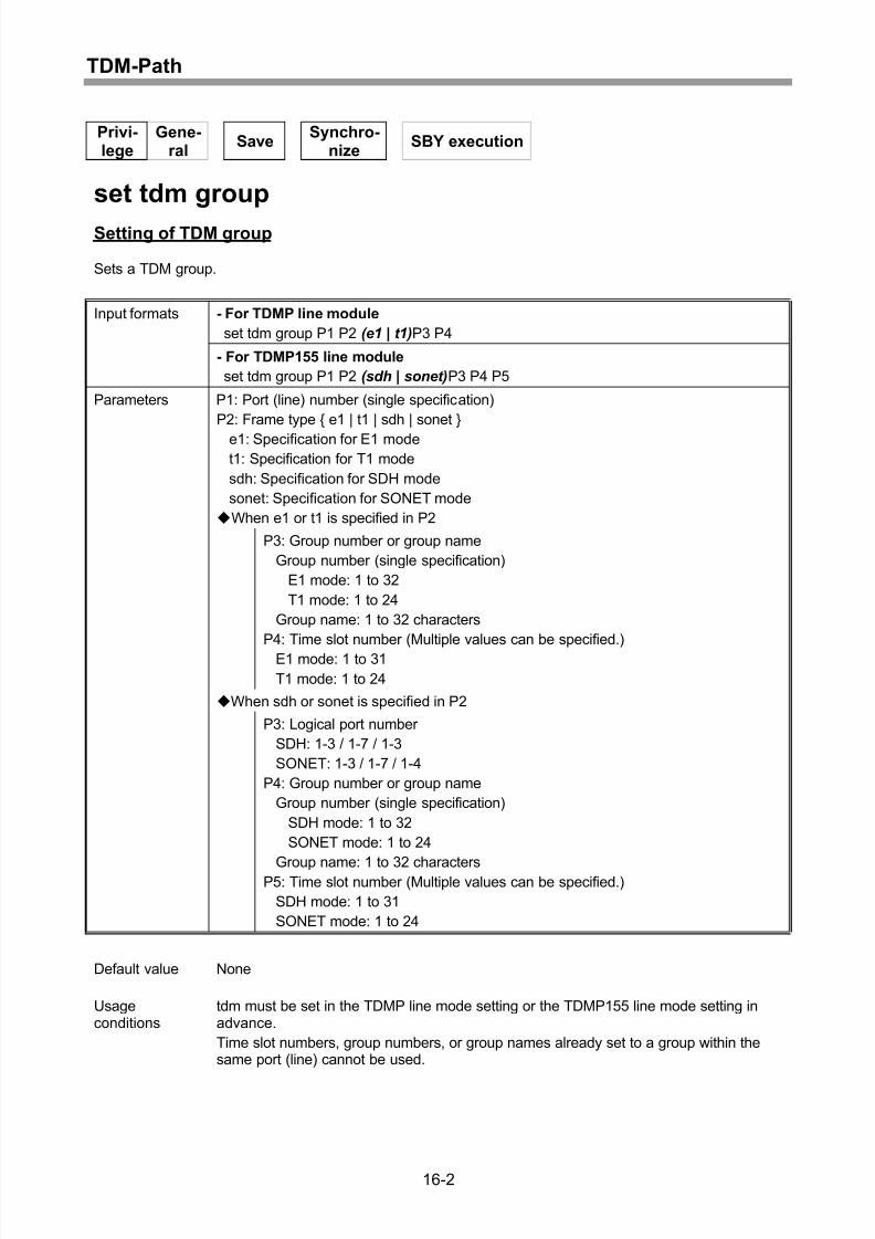
Setting of TDM group ...............................................................................................16-2
Display of TDM group setting information ................................................................16-4
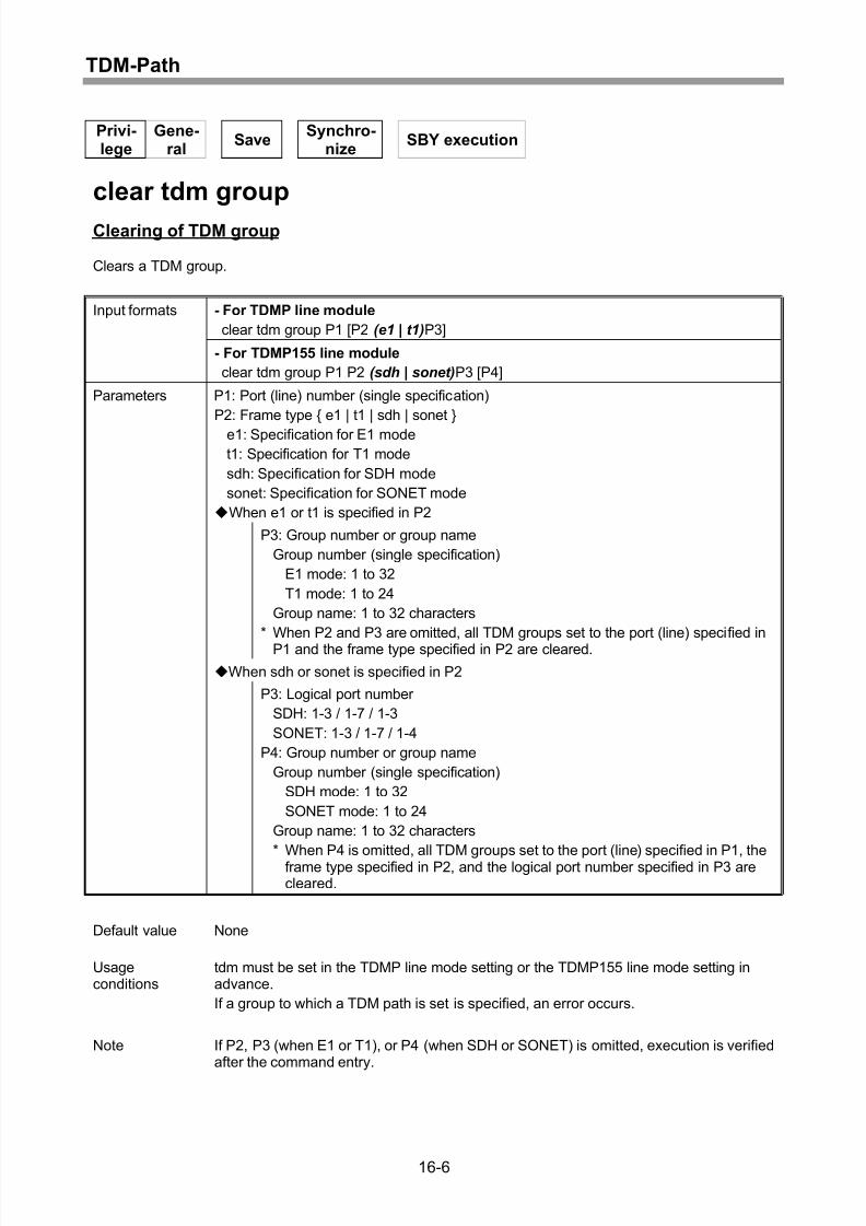
Clearing of TDM group.............................................................................................16-6
Setting of TDM group name .....................................................................................16-8
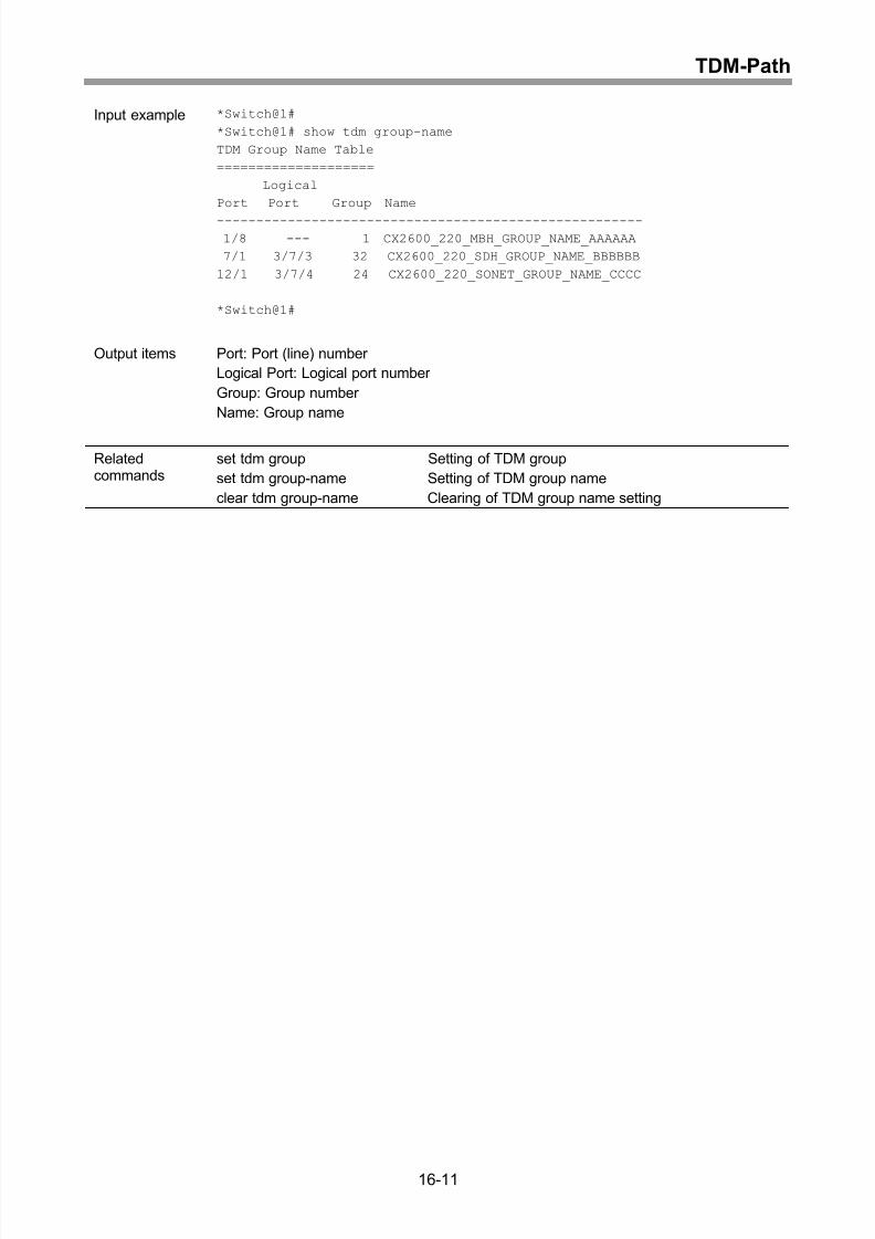
Display of TDM group name setting .......................................................................16-10
Clearing of TDM group name setting......................................................................16-12
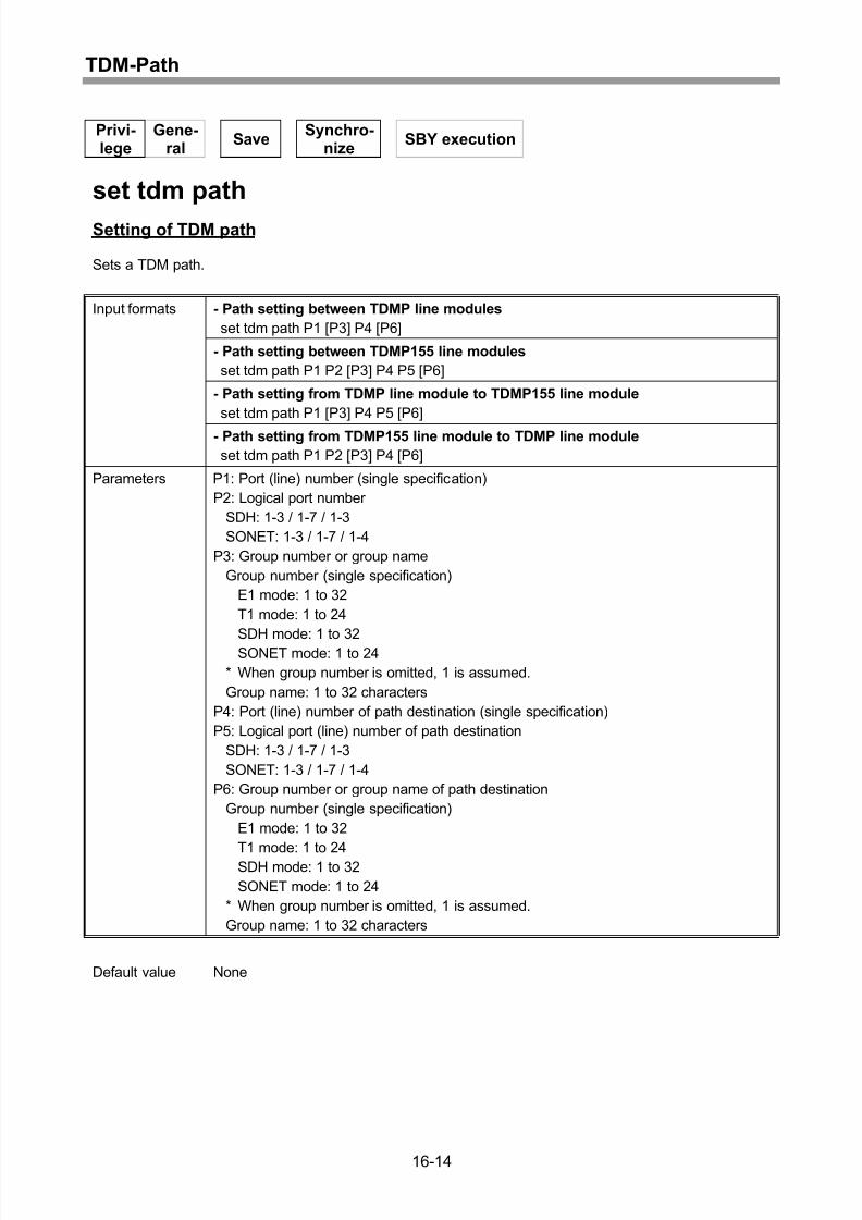
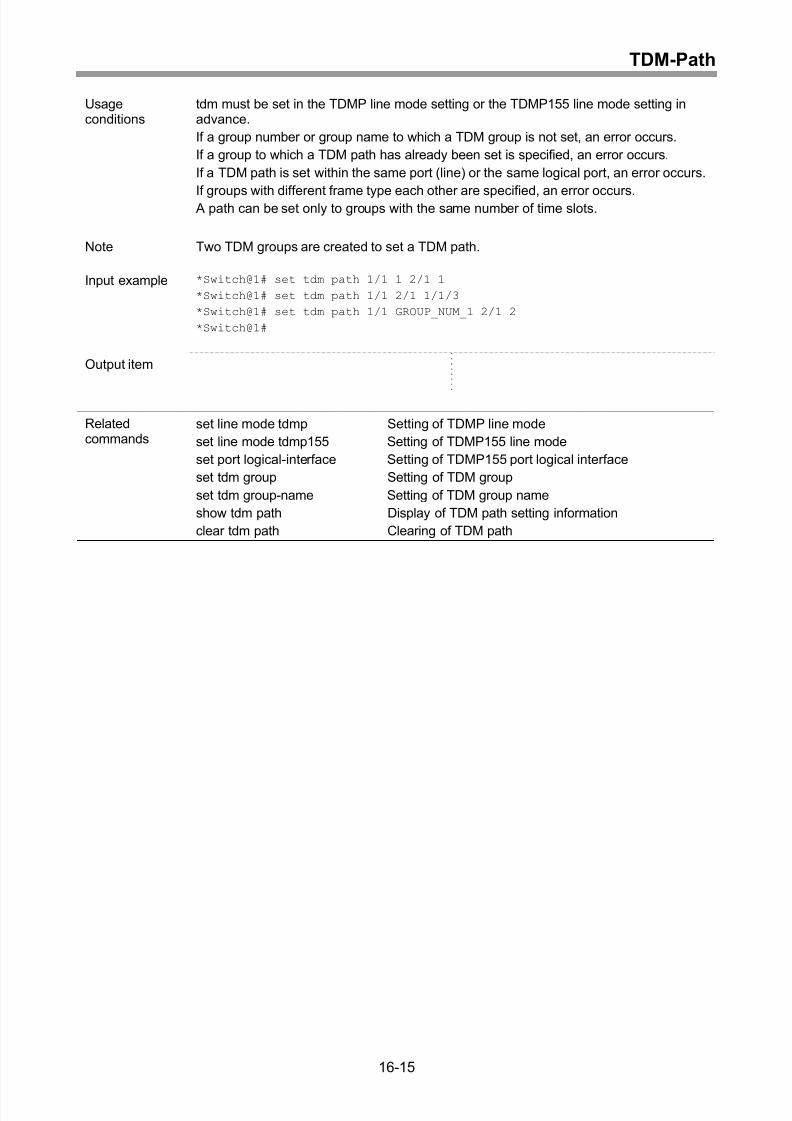
Setting of TDM path ...............................................................................................16-14
Display of TDM path setting information.................................................................16-16
Clearing of TDM path .............................................................................................16-18
xv
Page 20
8/21/2019 CX2600-220_Command_Reference_v7.6B_eng - Copy.pdf
http://slidepdf.com/reader/full/cx2600-220commandreferencev76beng-copypdf 20/758
Contents
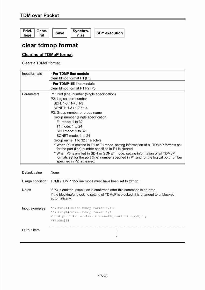
17 TDM over Packet...................................................................17-1
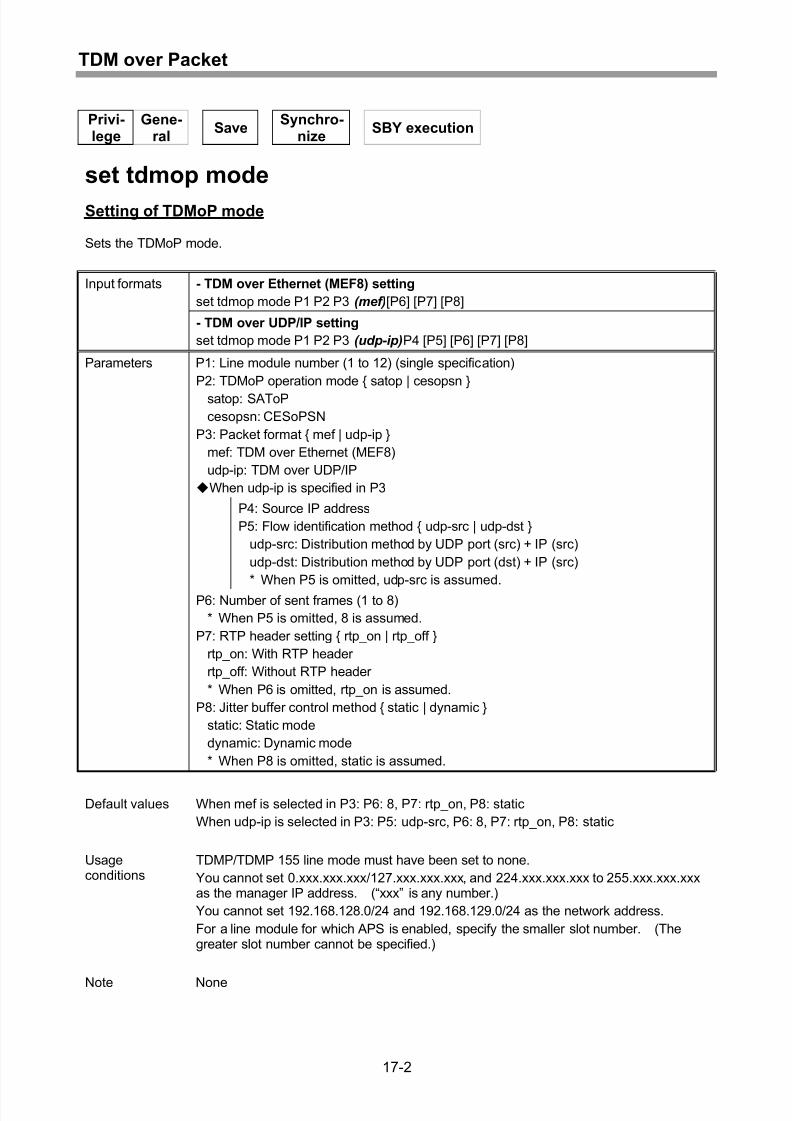
Setting of TDMoP mode...........................................................................................17-2
Clearing of TDMoP mode setting .............................................................................17-4
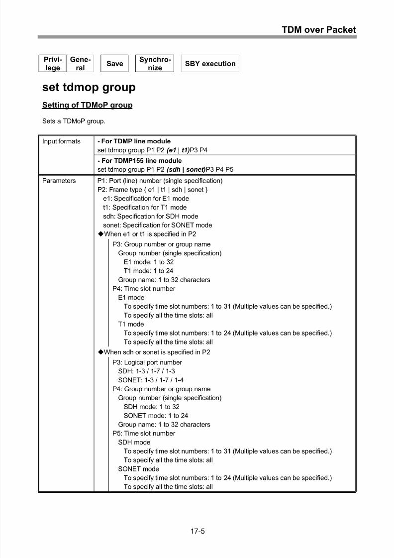
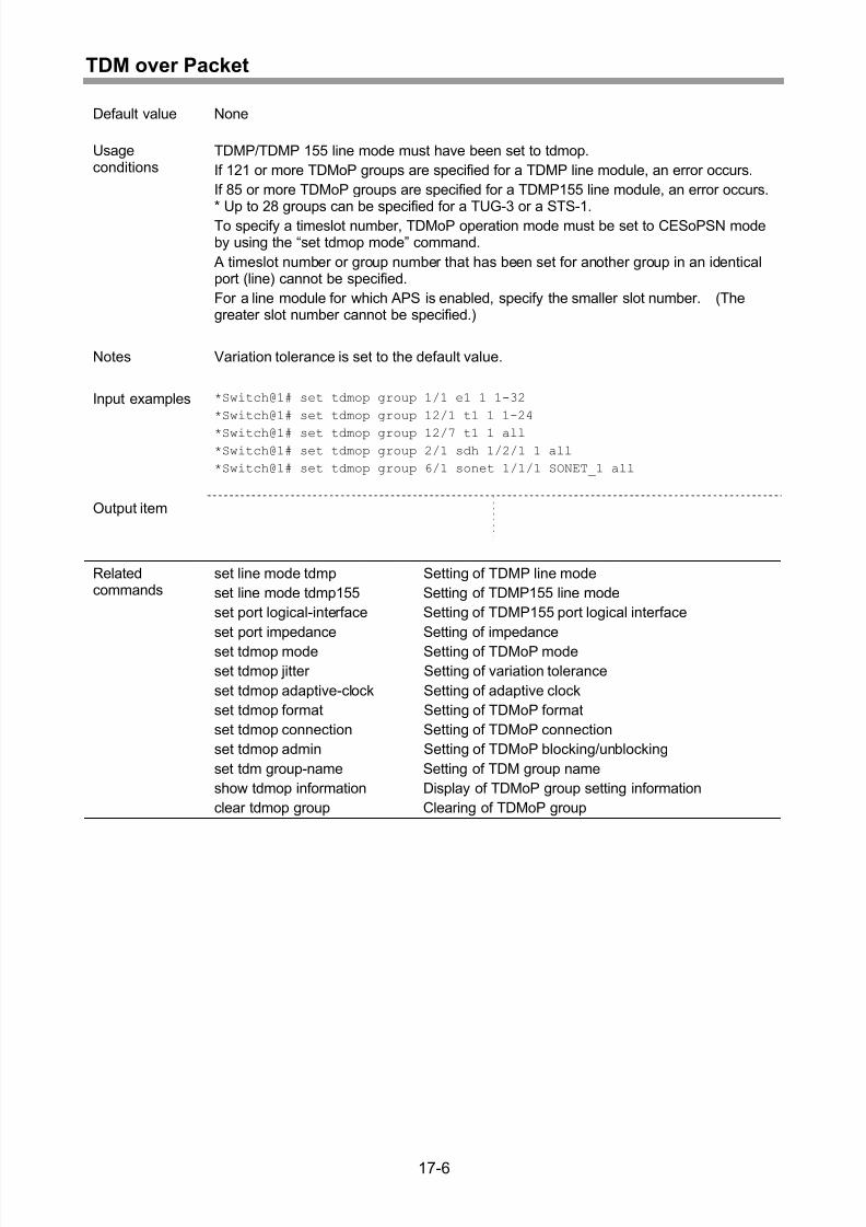
Setting of TDMoP group...........................................................................................17-5
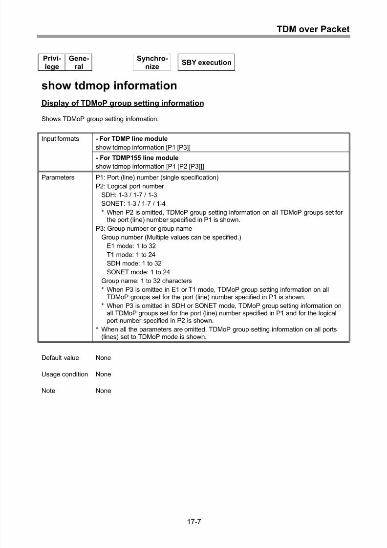
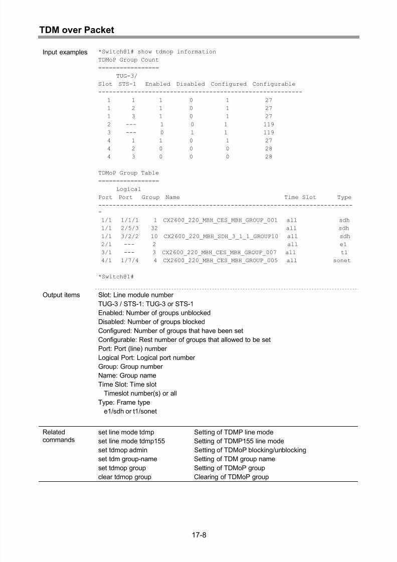
Display of TDMoP group setting information ............................................................17-7
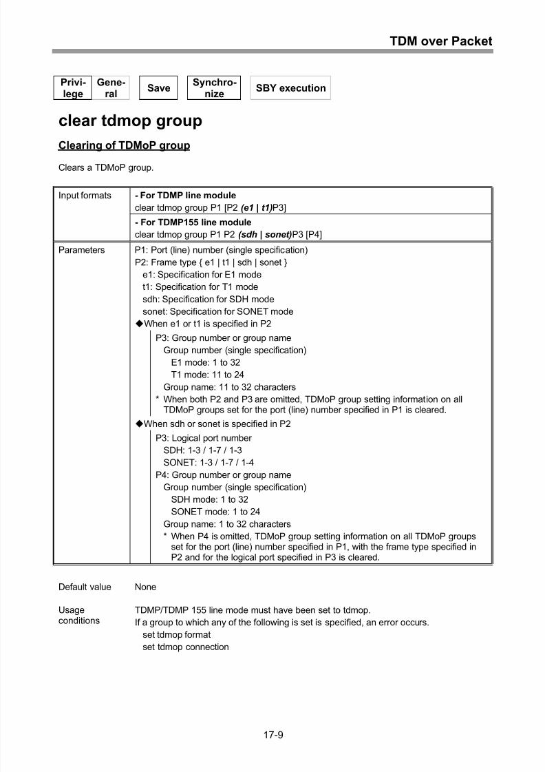
Clearing of TDMoP group.........................................................................................17-9
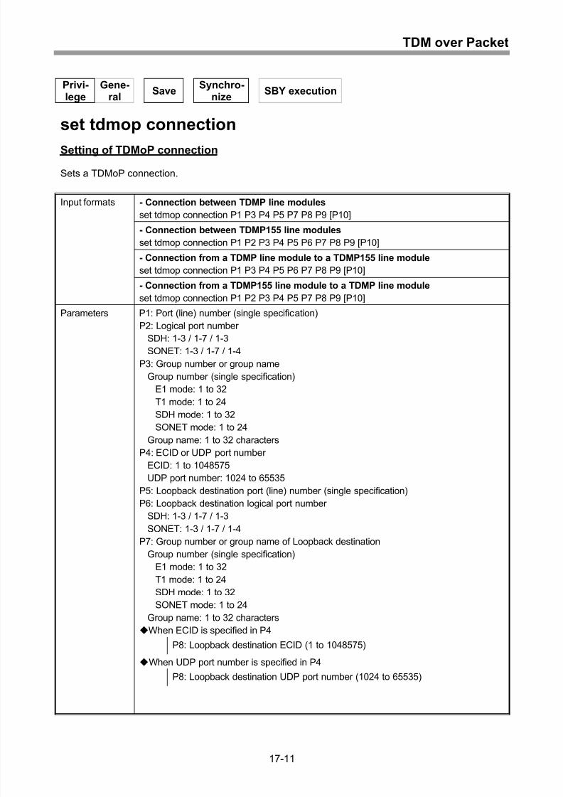
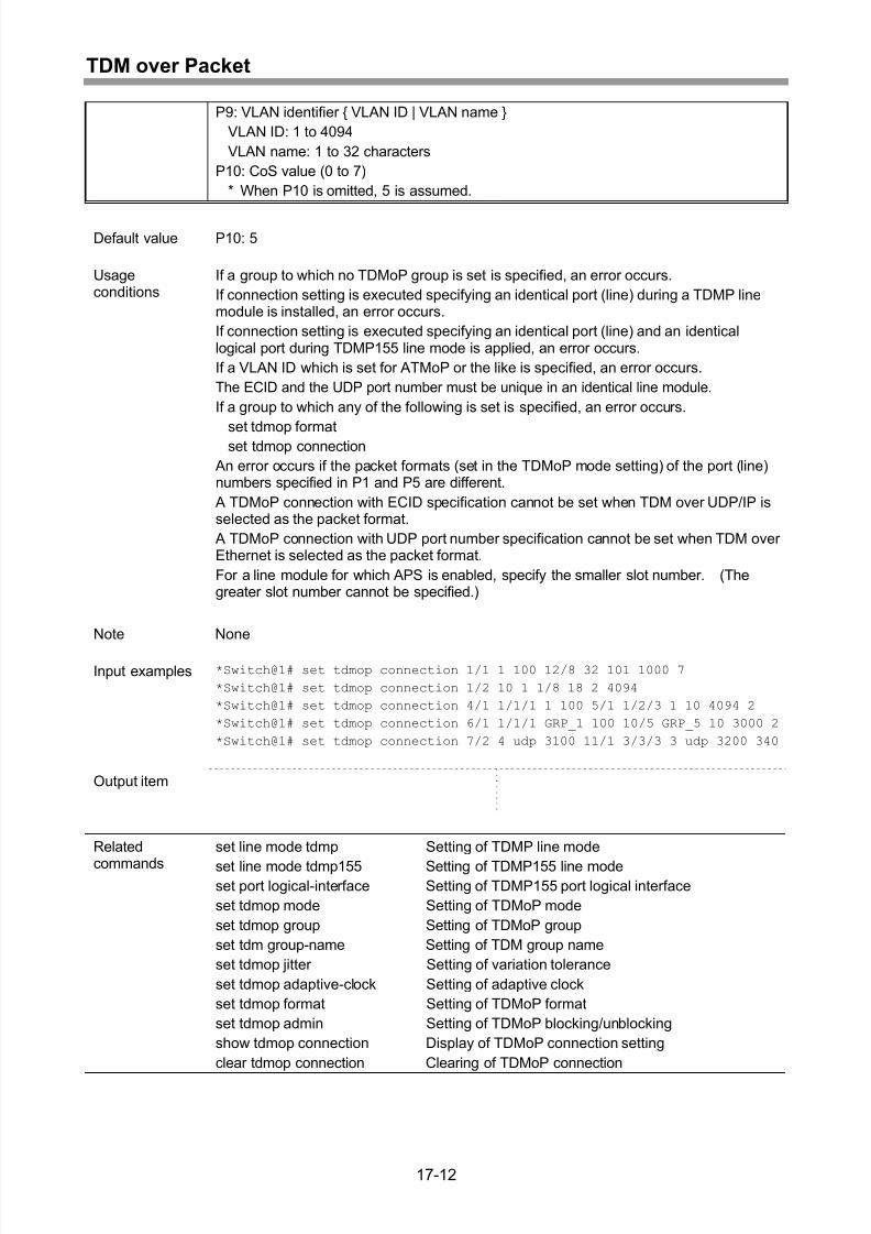
Setting of TDMoP connection.................................................................................17-11
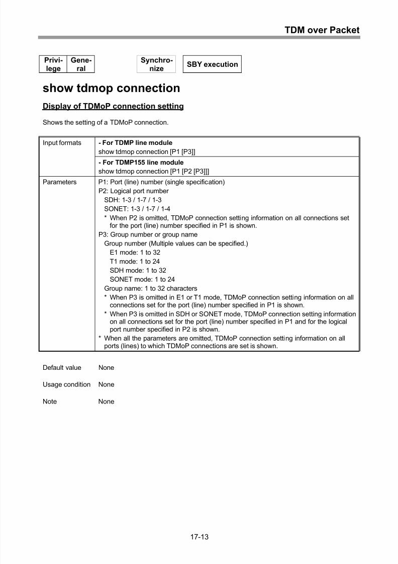
Display of TDMoP connection setting.....................................................................17-13
Clearing of TDMoP connection ..............................................................................17-16
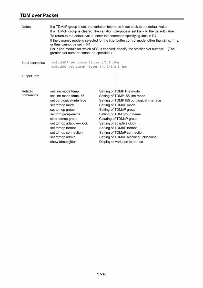
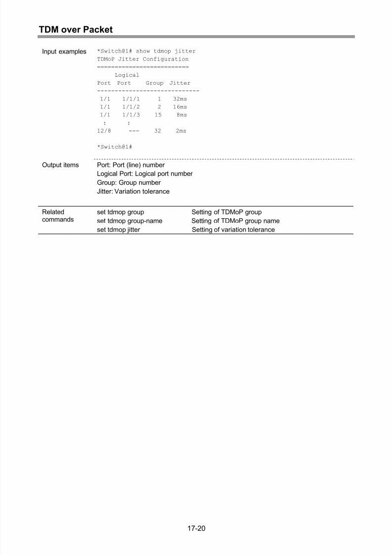
Setting of variation tolerance..................................................................................17-17
Display of variation tolerance .................................................................................17-19
Display of TDMoP path setting status information..................................................17-21
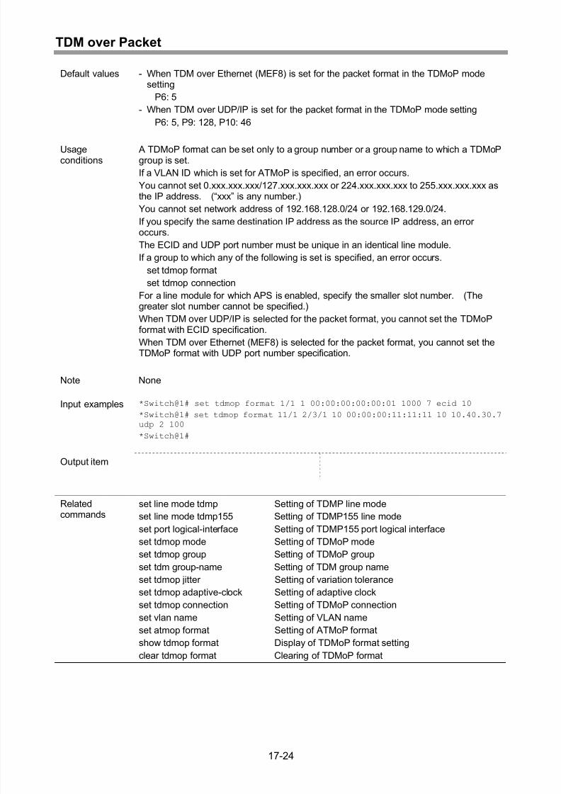
Setting of TDMoP format........................................................................................17-23
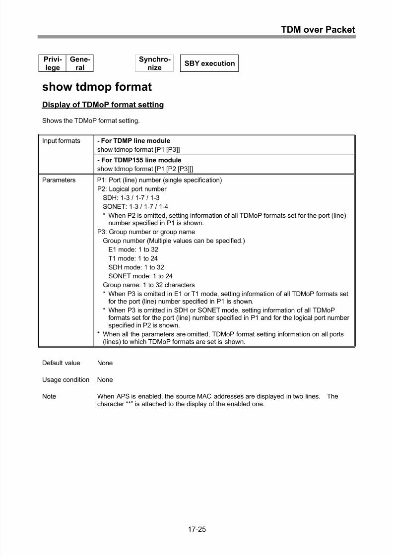
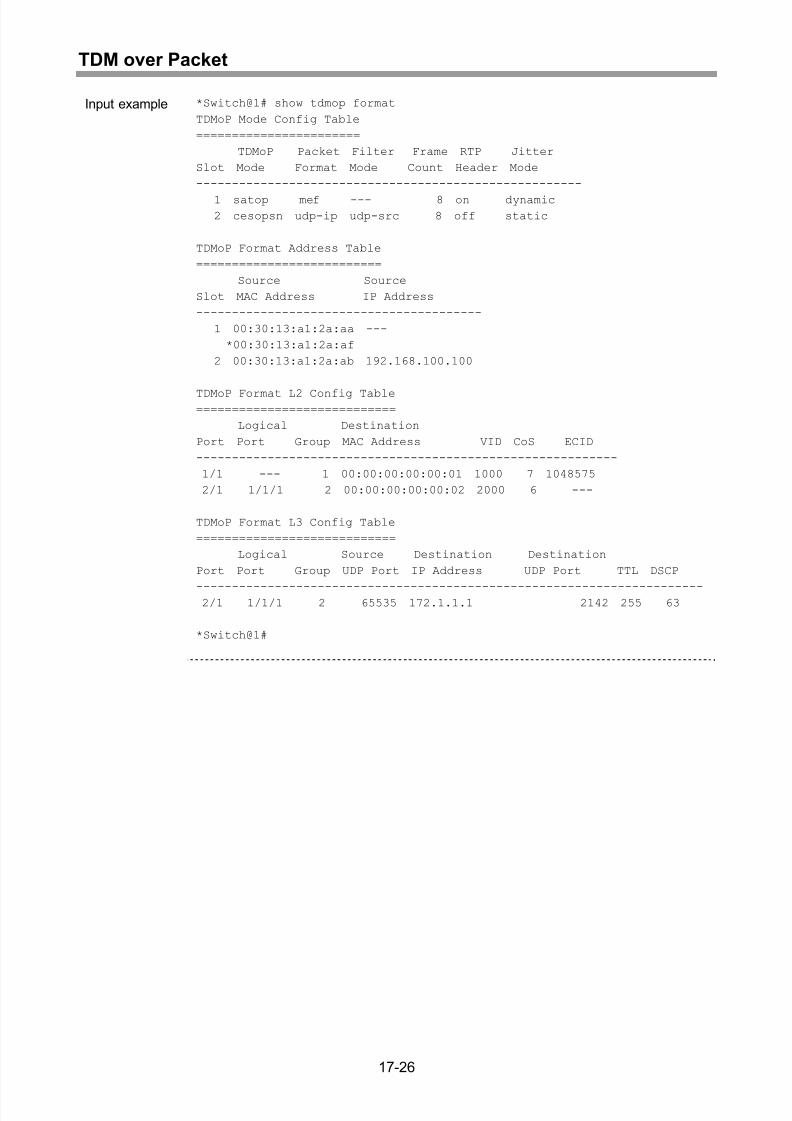
Display of TDMoP format setting............................................................................17-25
Clearing of TDMoP format......................................................................................17-28
Setting of TDMoP blocking/unblocking...................................................................17-30
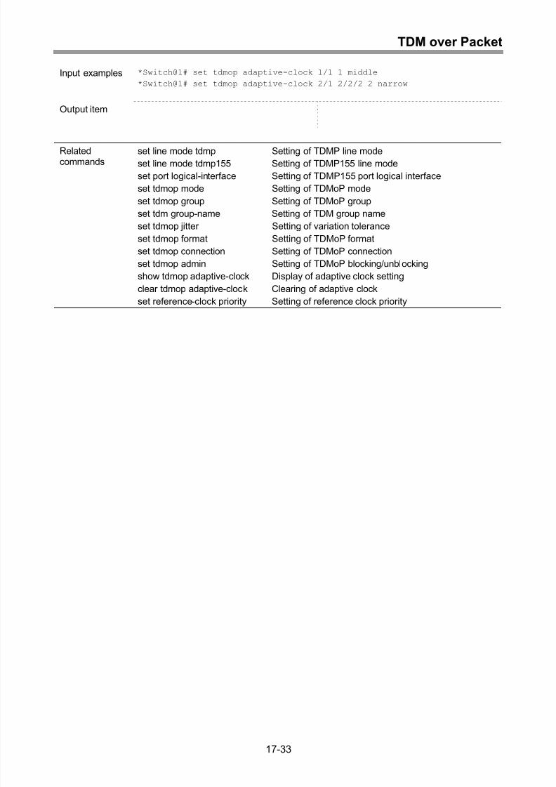
Setting of adaptive clock ........................................................................................17-32
Display of adaptive clock setting ............................................................................17-34
Clearing of adaptive clock ......................................................................................17-35
18 Clock Control ........................................................................18-1
Setting of external clock mode .................................................................................18-2
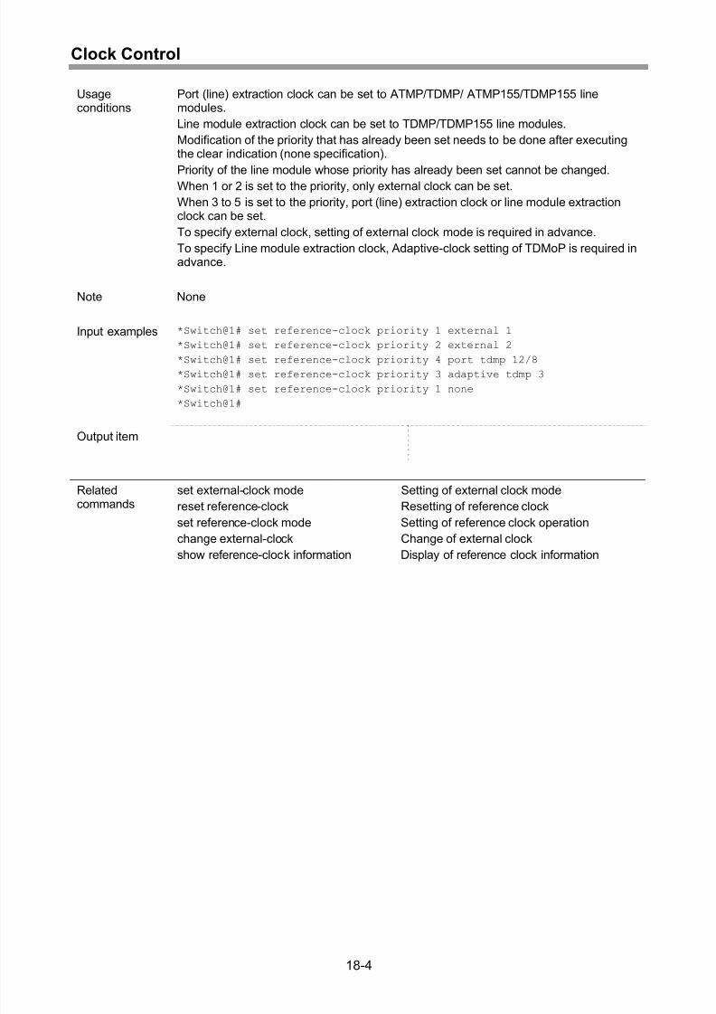
Setting of reference clock priority .............................................................................18-3
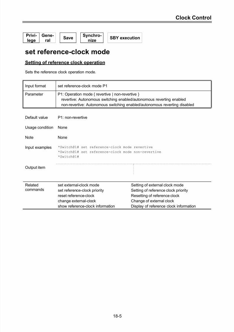
Setting of reference clock operation.........................................................................18-5
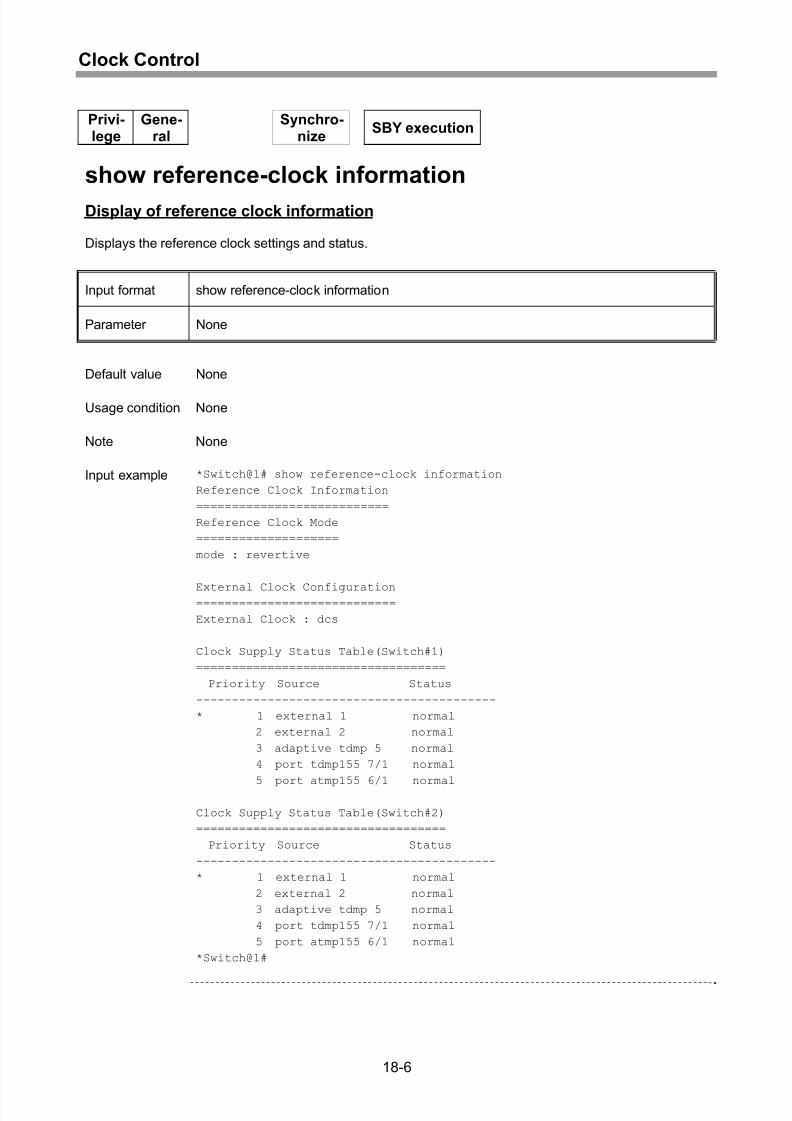
Display of reference clock information......................................................................18-6
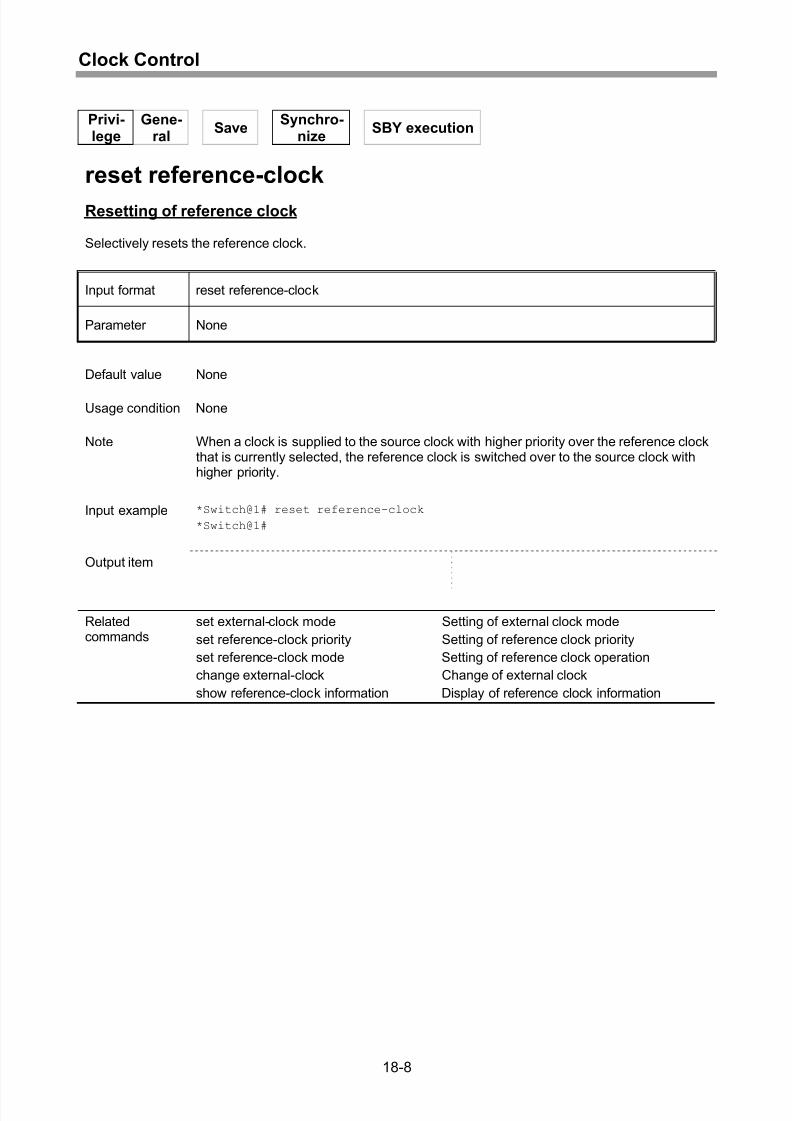
Resetting of reference clock.....................................................................................18-8
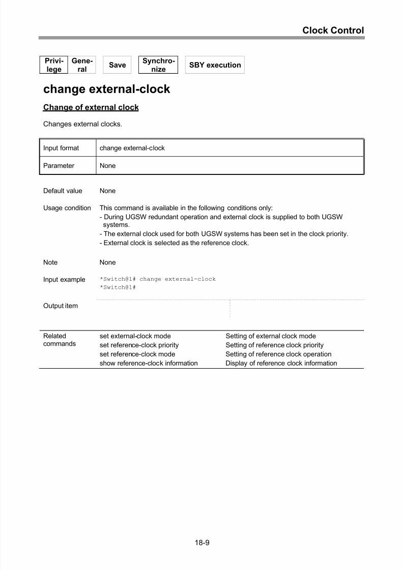
Change of external clock..........................................................................................18-9
19 Network Management ........................................................19-11
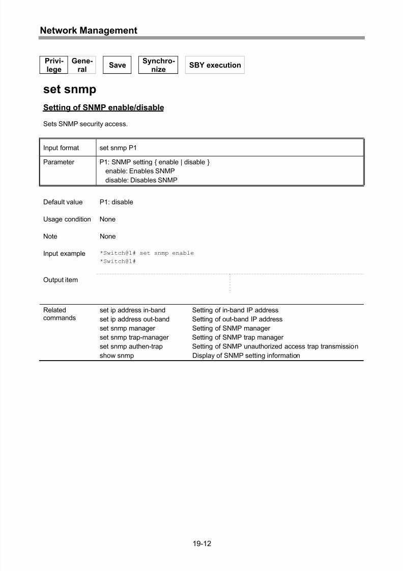
Setting of SNMP enable/disable.............................................................................19-12
Setting of SNMP manager......................................................................................19-13
Setting of SNMP trap manager ..............................................................................19-14
Clearing of SNMP manager settings ......................................................................19-15
Clearing of SNMP trap manager settings...............................................................19-16
Setting of SNMP unauthorized access trap transmission.......................................19-17
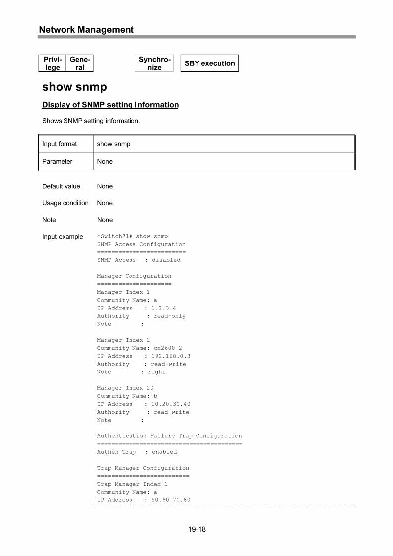
Display of SNMP setting information......................................................................19-18
Setting of access list...............................................................................................19-20
xvi
Page 21
8/21/2019 CX2600-220_Command_Reference_v7.6B_eng - Copy.pdf
http://slidepdf.com/reader/full/cx2600-220commandreferencev76beng-copypdf 21/758
Contents
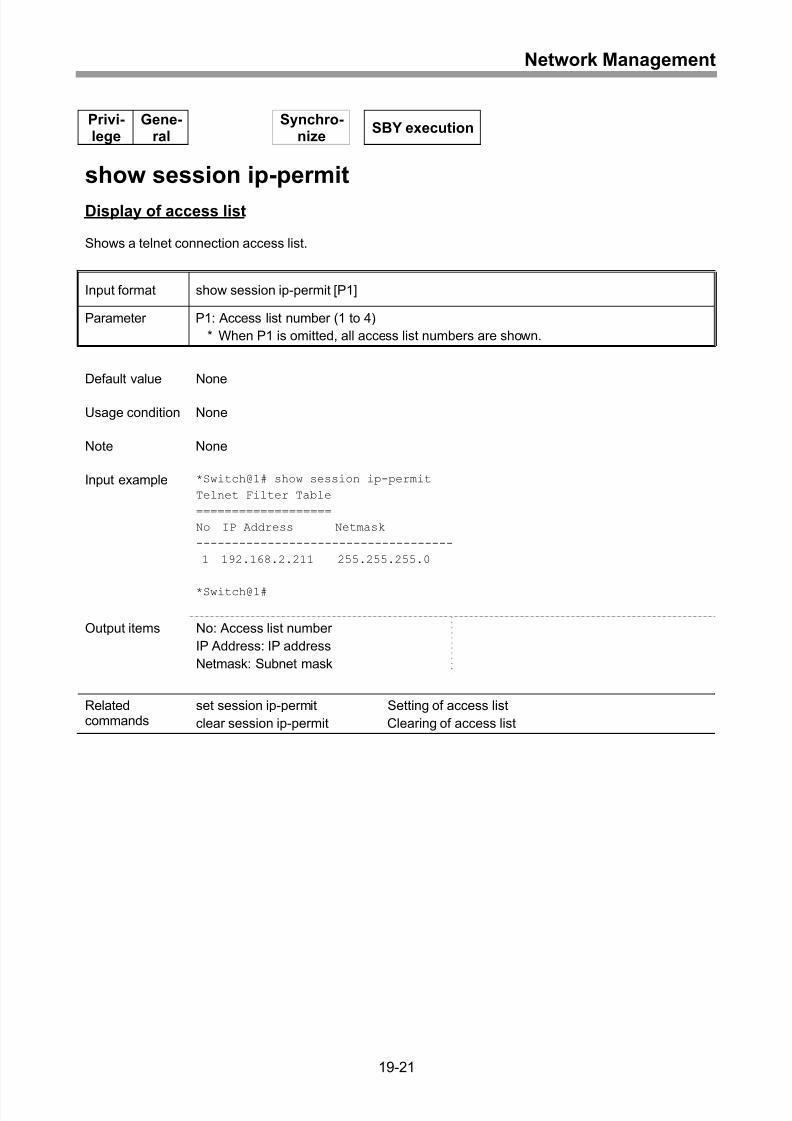
Display of access list..............................................................................................19-21
Clearing of access list ............................................................................................19-22
Display of session ..................................................................................................19-23
Clearing of session.................................................................................................19-24
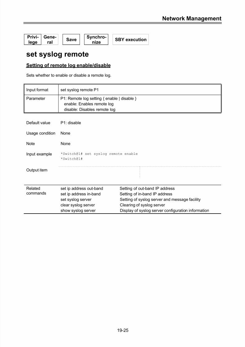
Setting of remote log enable/disable ......................................................................19-25
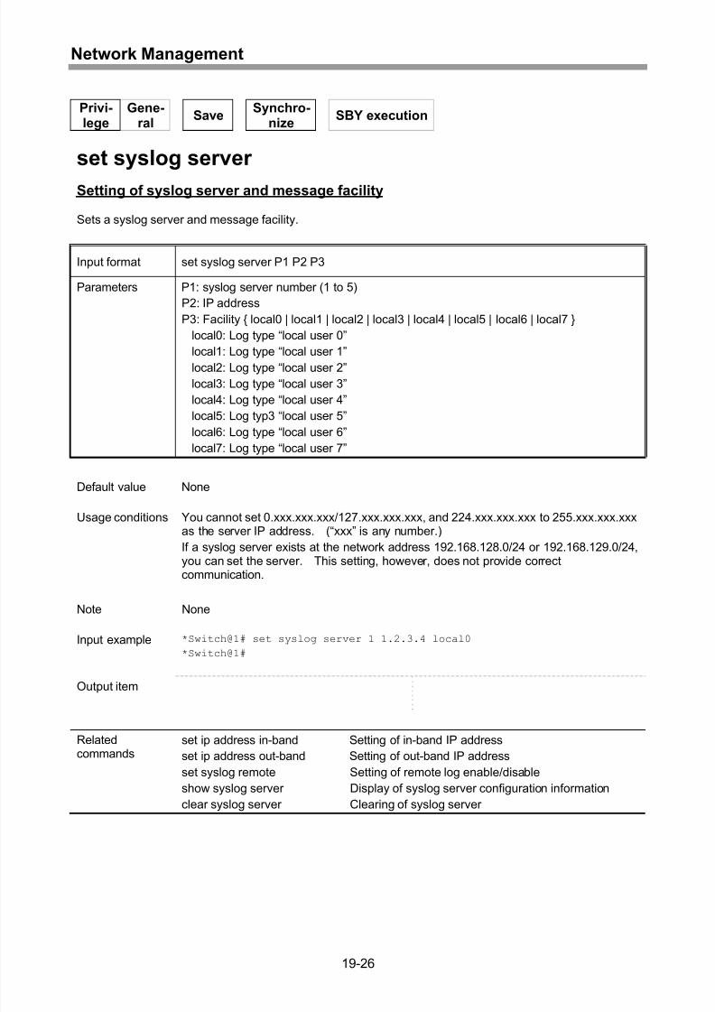
Setting of syslog server and message facility.........................................................19-26
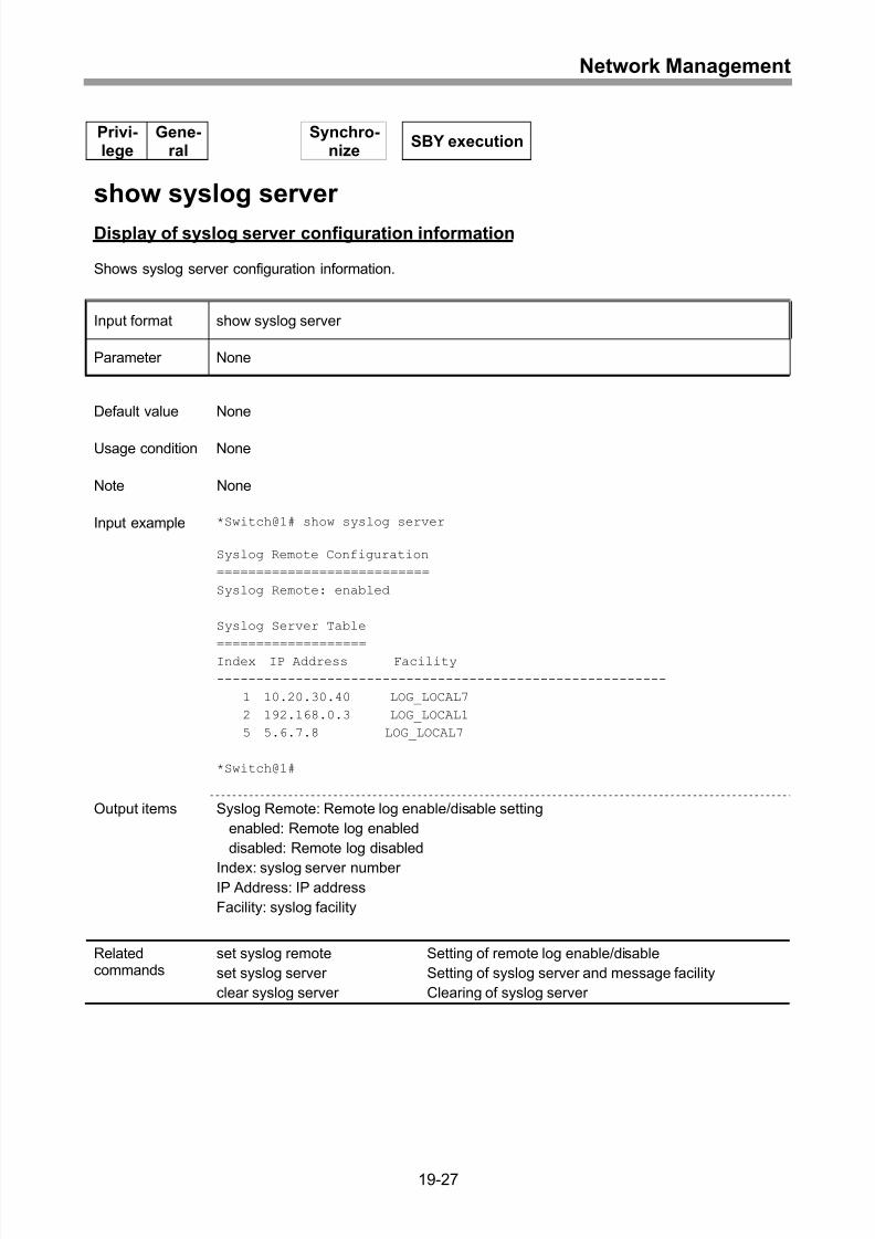
Display of syslog server configuration information .................................................19-27
Clearing of syslog server........................................................................................19-28
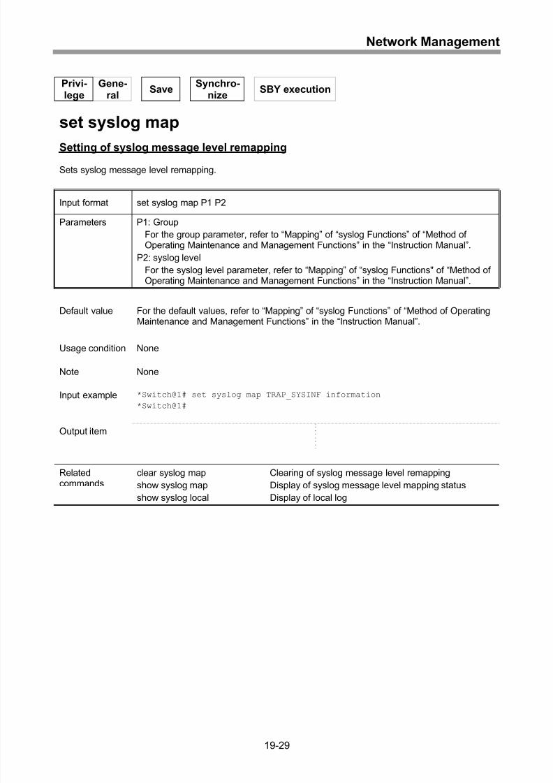
Setting of syslog message level remapping ...........................................................19-29
Display of syslog message level mapping status ...................................................19-30
Clearing of syslog message level remapping .........................................................19-31
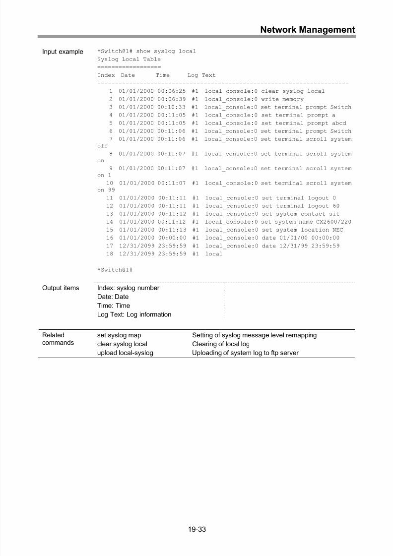
Display of local log .................................................................................................19-32
Clearing of local log................................................................................................19-34
Setting of NTP access time....................................................................................19-35
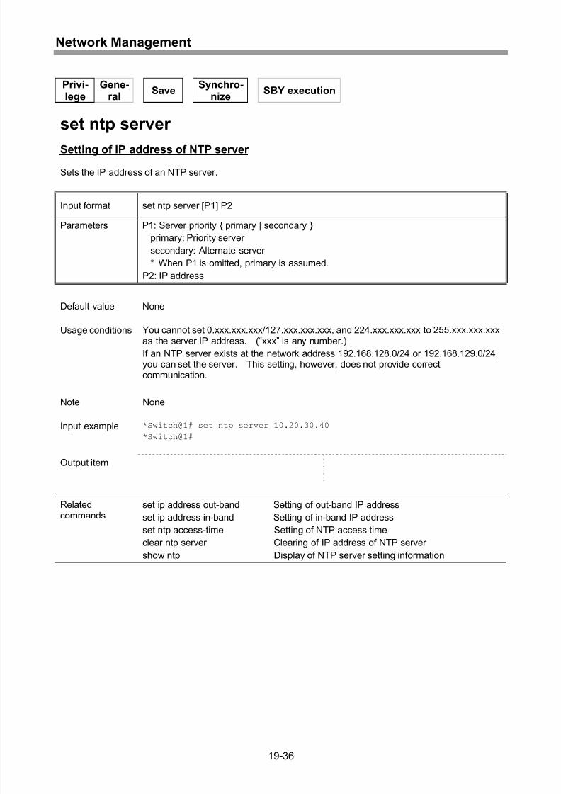
Setting of IP address of NTP server.......................................................................19-36
Display of NTP server setting information ..............................................................19-37
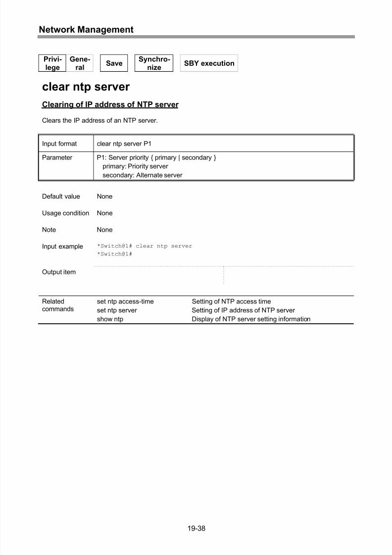
Clearing of IP address of NTP server.....................................................................19-38
20 Network Test .........................................................................20-1
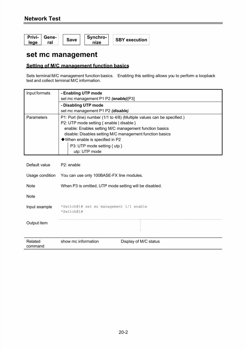
Setting of M/C management function basics ............................................................20-2
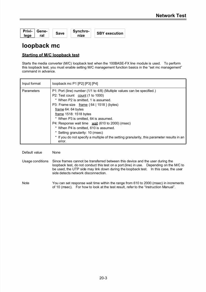
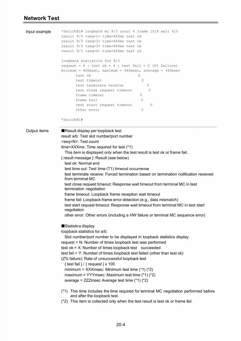
Starting of M/C loopback test ...................................................................................20-3
Prompting of M/C to send M/C status notification ....................................................20-6
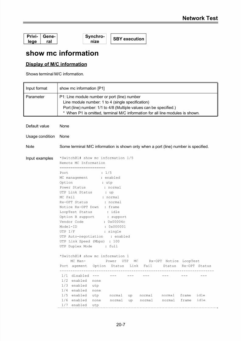
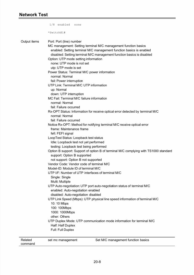
Display of M/C information .......................................................................................20-7
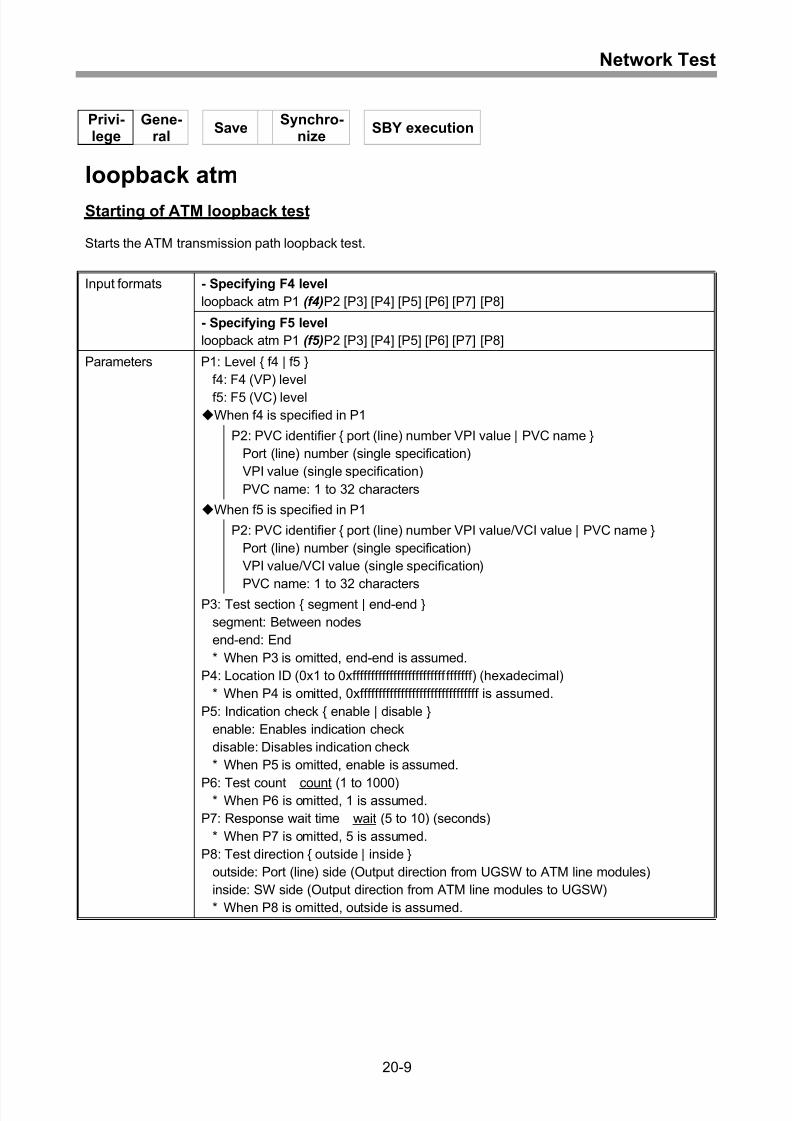
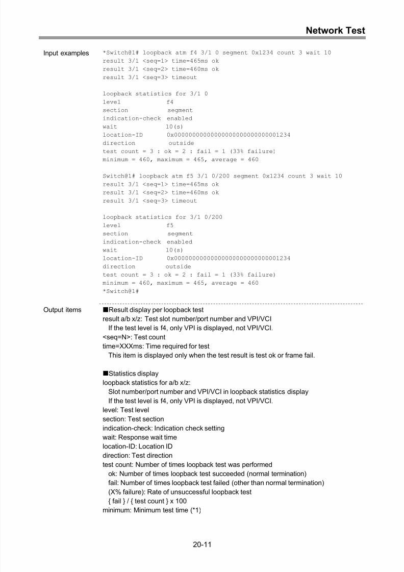
Starting of ATM loopback test ..................................................................................20-9
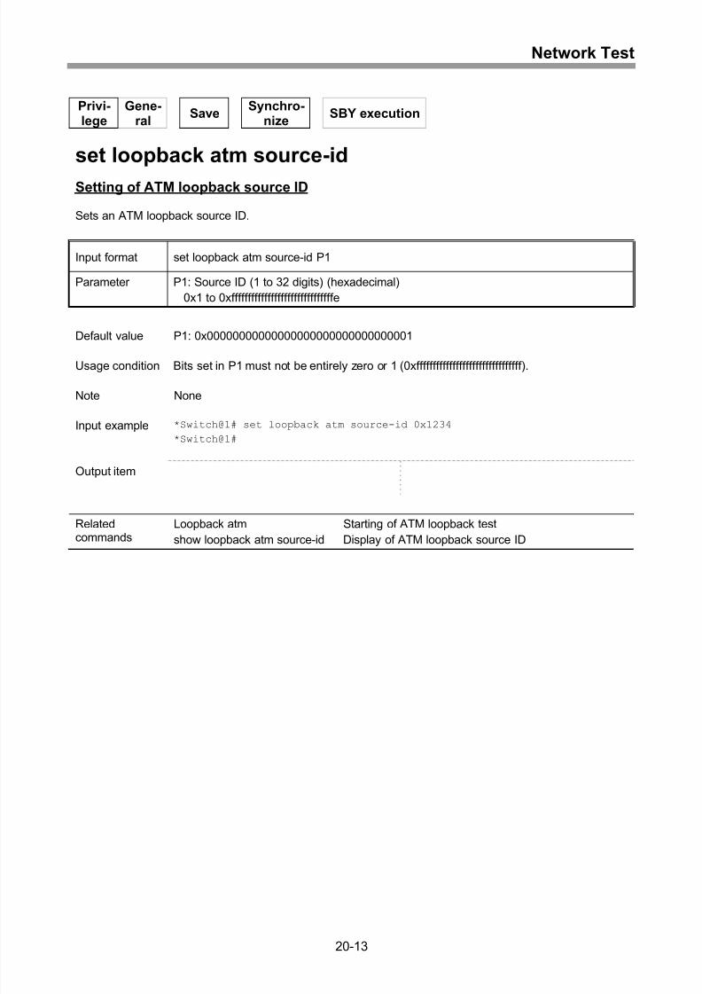
Setting of ATM loopback source ID........................................................................20-13
Display of ATM loopback source ID .......................................................................20-14
Setting of ATM loopback monitoring mode.............................................................20-15
Display of ATM loopback monitoring configuration ................................................20-16
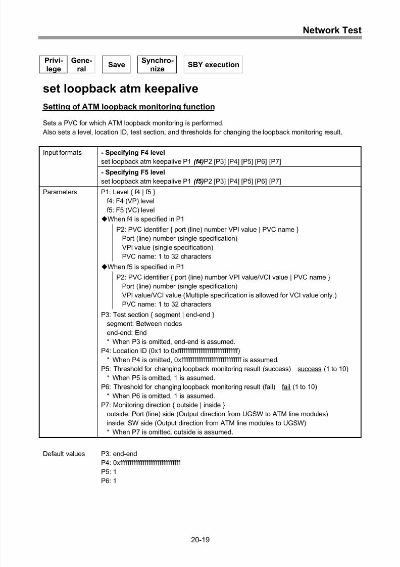
Setting of ATM loopback monitoring function .........................................................20-19
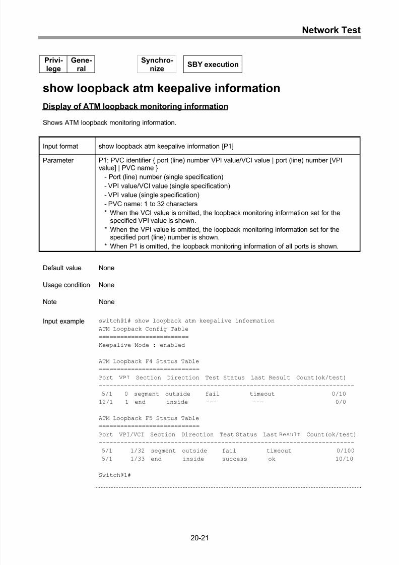
Display of ATM loopback monitoring information ...................................................20-21
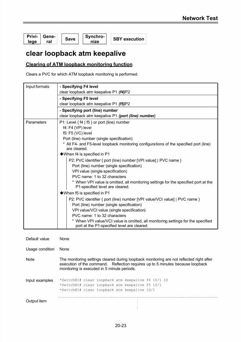
Clearing of ATM loopback monitoring function.......................................................20-23
21 Monitors.................................................................................21-1
Display of port counter .............................................................................................21-2
Clearing of port counter............................................................................................21-5
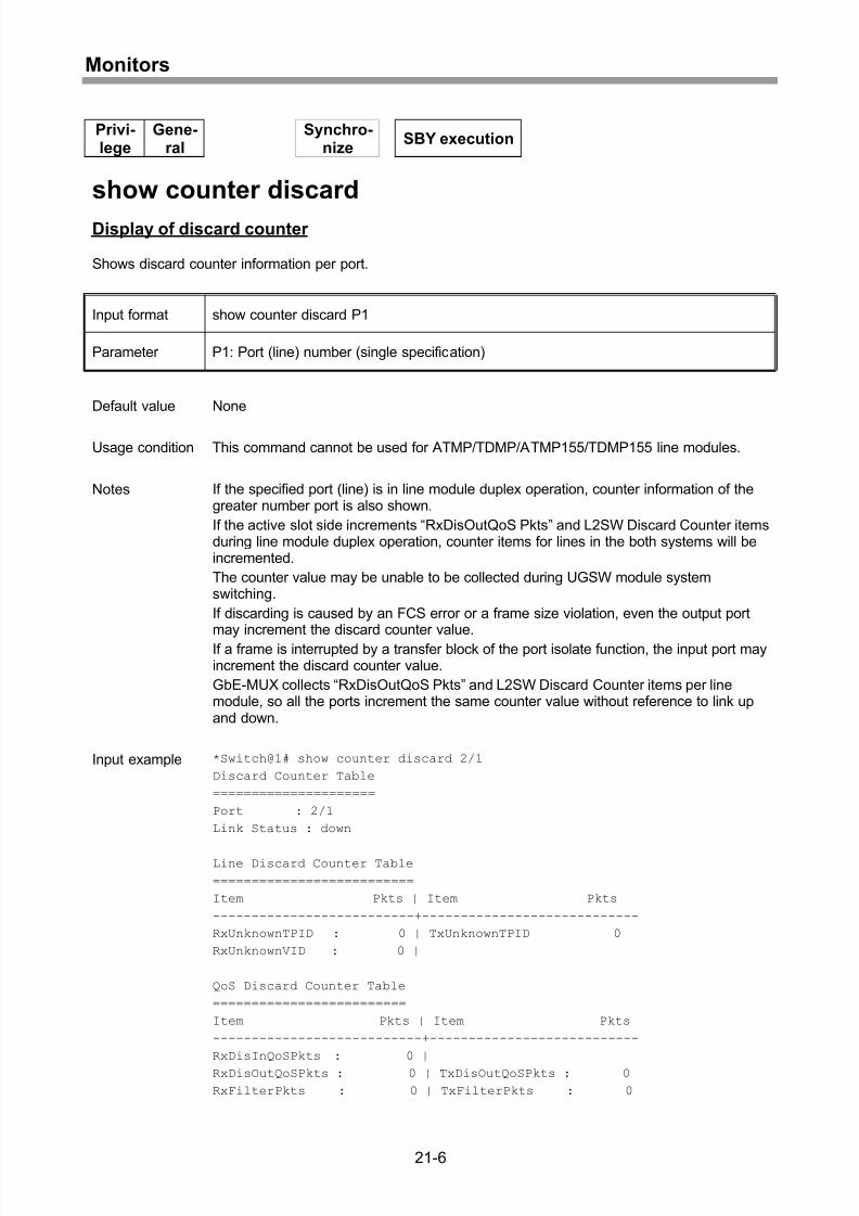
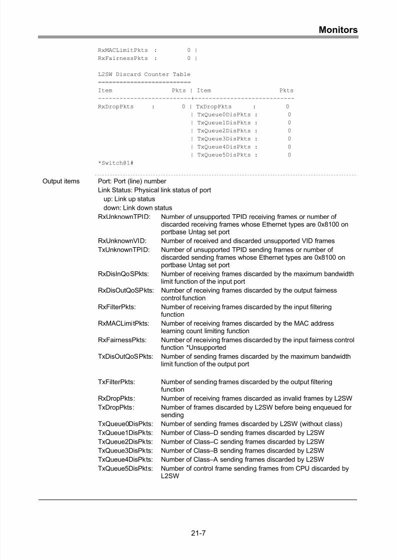
Display of discard counter ........................................................................................21-6
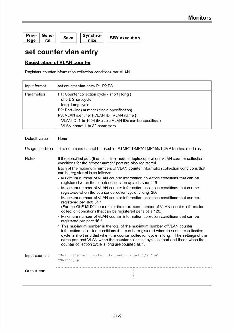
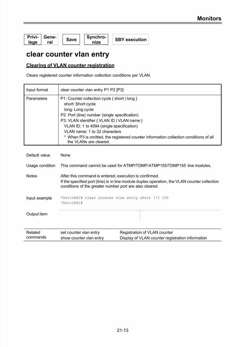
Registration of VLAN counter...................................................................................21-9
Display of VLAN counter registration information...................................................21-11
xvii
Page 22
8/21/2019 CX2600-220_Command_Reference_v7.6B_eng - Copy.pdf
http://slidepdf.com/reader/full/cx2600-220commandreferencev76beng-copypdf 22/758
Contents
Clearing of VLAN counter registration....................................................................21-13
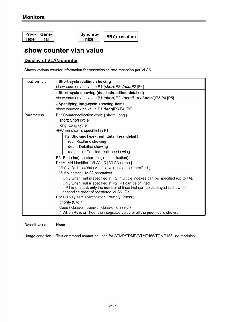
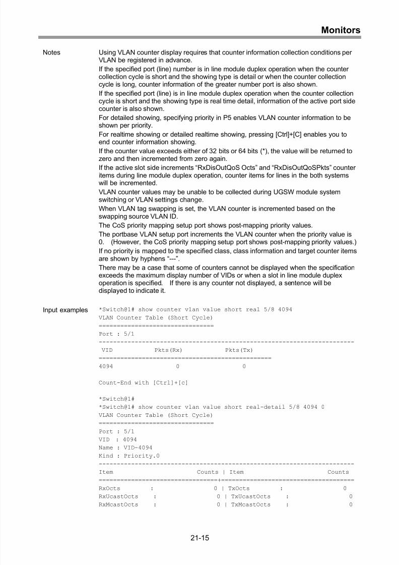
Display of VLAN counter ........................................................................................21-14
Clearing of VLAN counter.......................................................................................21-19
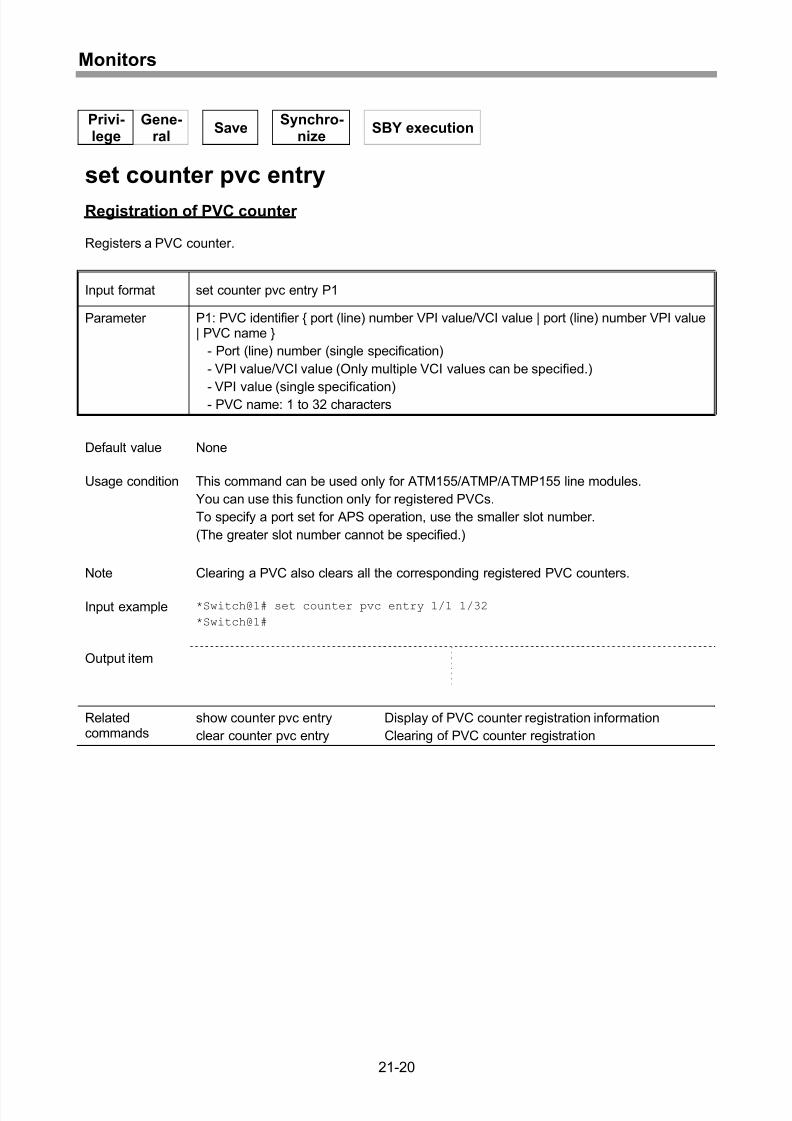
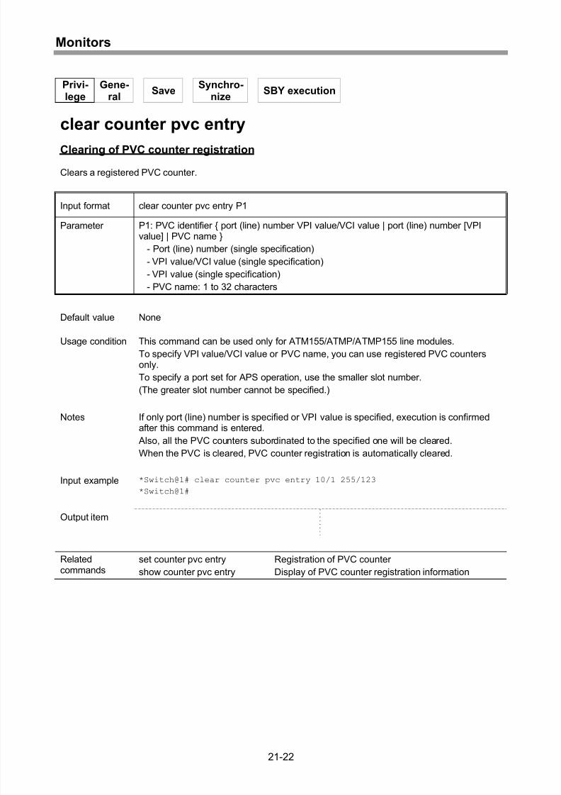
Registration of PVC counter...................................................................................21-20
Display of PVC counter registration information.....................................................21-21
Clearing of PVC counter registration......................................................................21-22
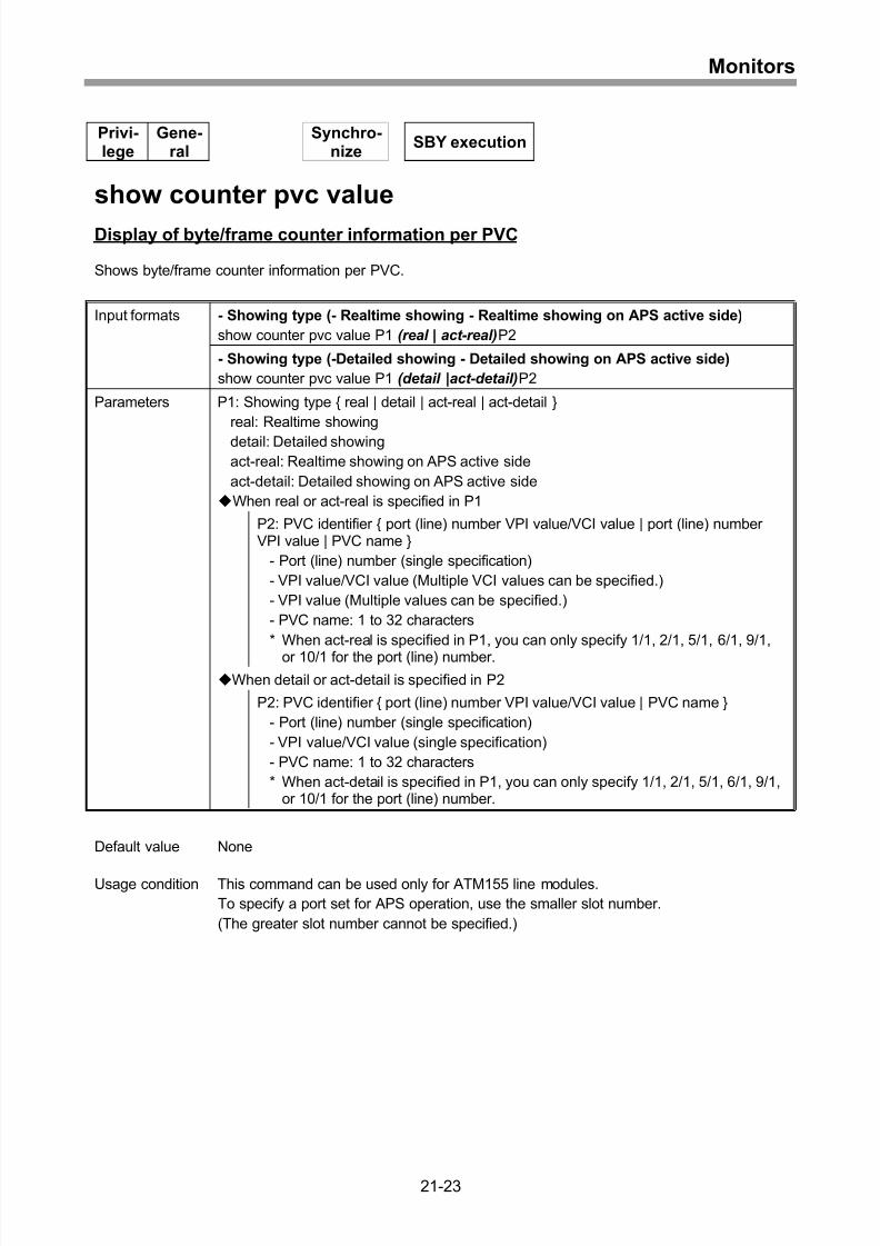
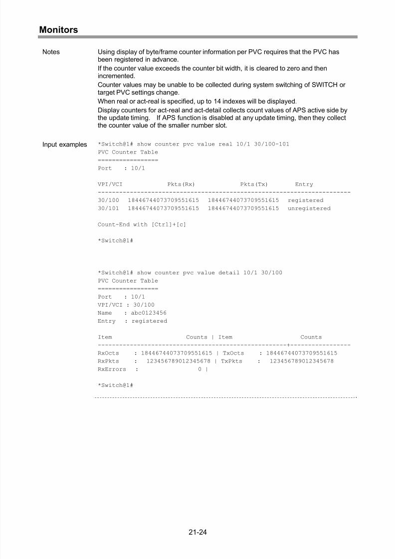
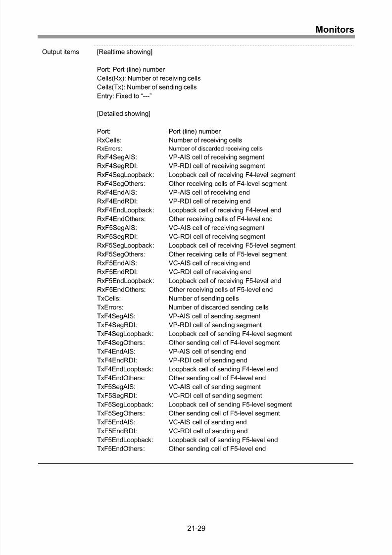
Display of byte/frame counter information per PVC ...............................................21-23
Clearing of byte/frame counter information per PVC..............................................21-26
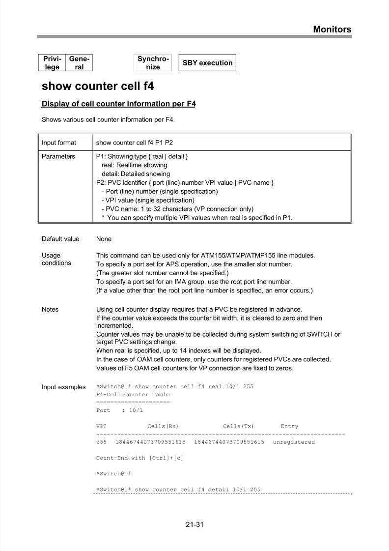
Display of cell counter information .........................................................................21-27
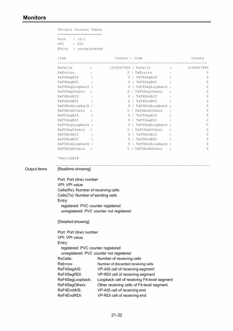
Display of cell counter information per F4 ..............................................................21-31
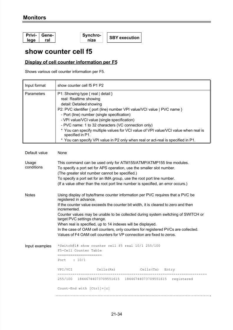
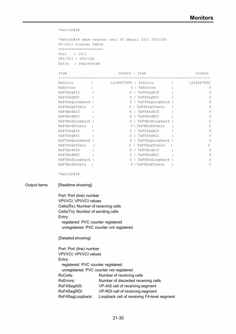
Display of cell counter information per F5 ..............................................................21-34
Display of cell counter information per IMA port.....................................................21-37
Clearing of cell counter information........................................................................21-39
Registration of EtherOAM counter .........................................................................21-40
Display of EtherOAM counter registration information............................................21-41
Clearing of EtherOAM counter registration.............................................................21-43
Display of EtherOAM counter.................................................................................21-44
Setting of mirroring start or stop .............................................................................21-45
Display of mirroring settings ...................................................................................21-47
22 Maintenance and Operation ................................................22-1
Uploading of running configuration to ftp server.......................................................22-2
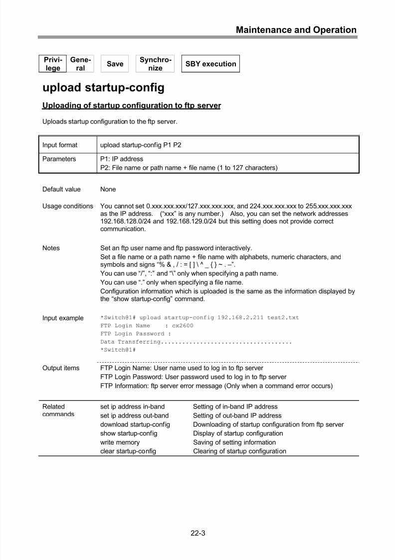
Uploading of startup configuration to ftp server........................................................22-3
Uploading of system log to ftp server .......................................................................22-4
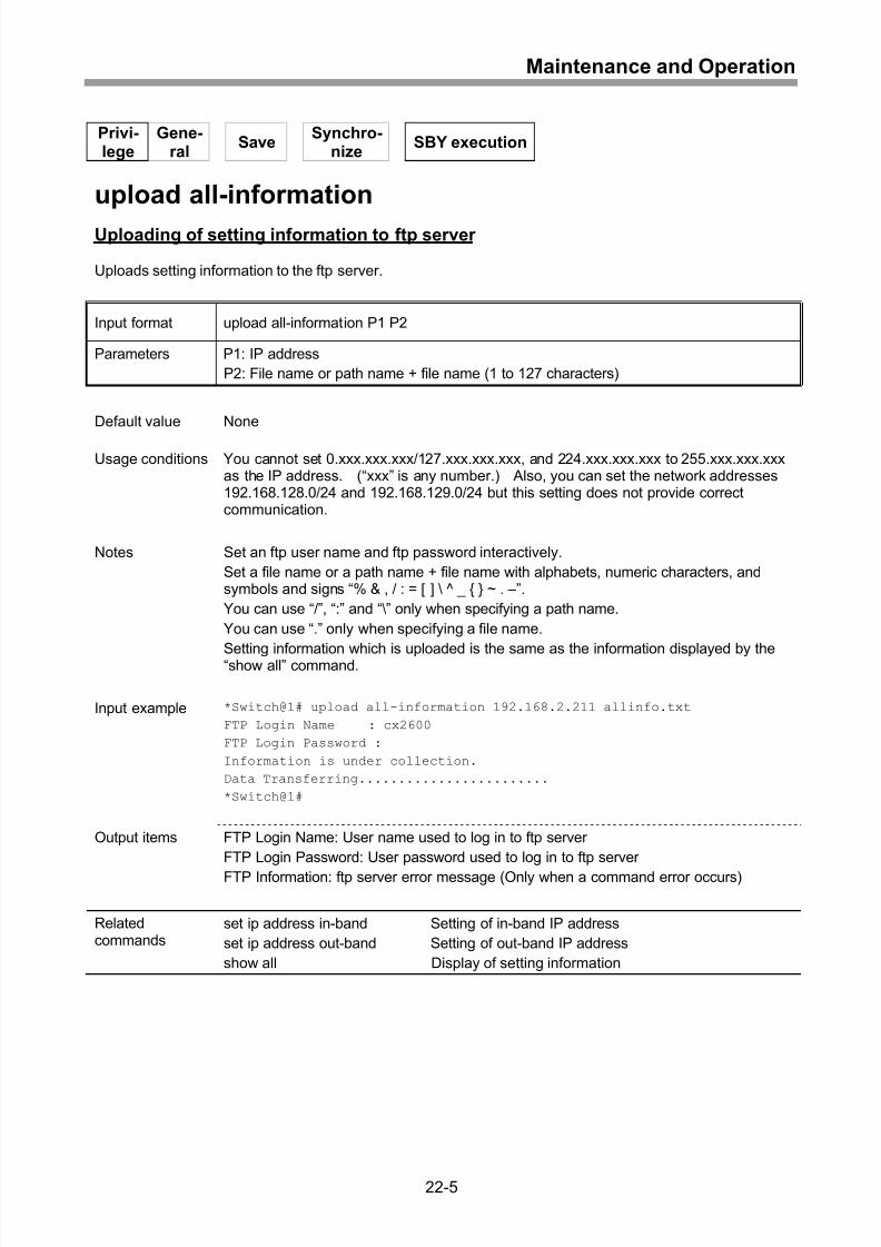
Uploading of setting information to ftp server...........................................................22-5
Uploading of fault information to ftp server...............................................................22-6
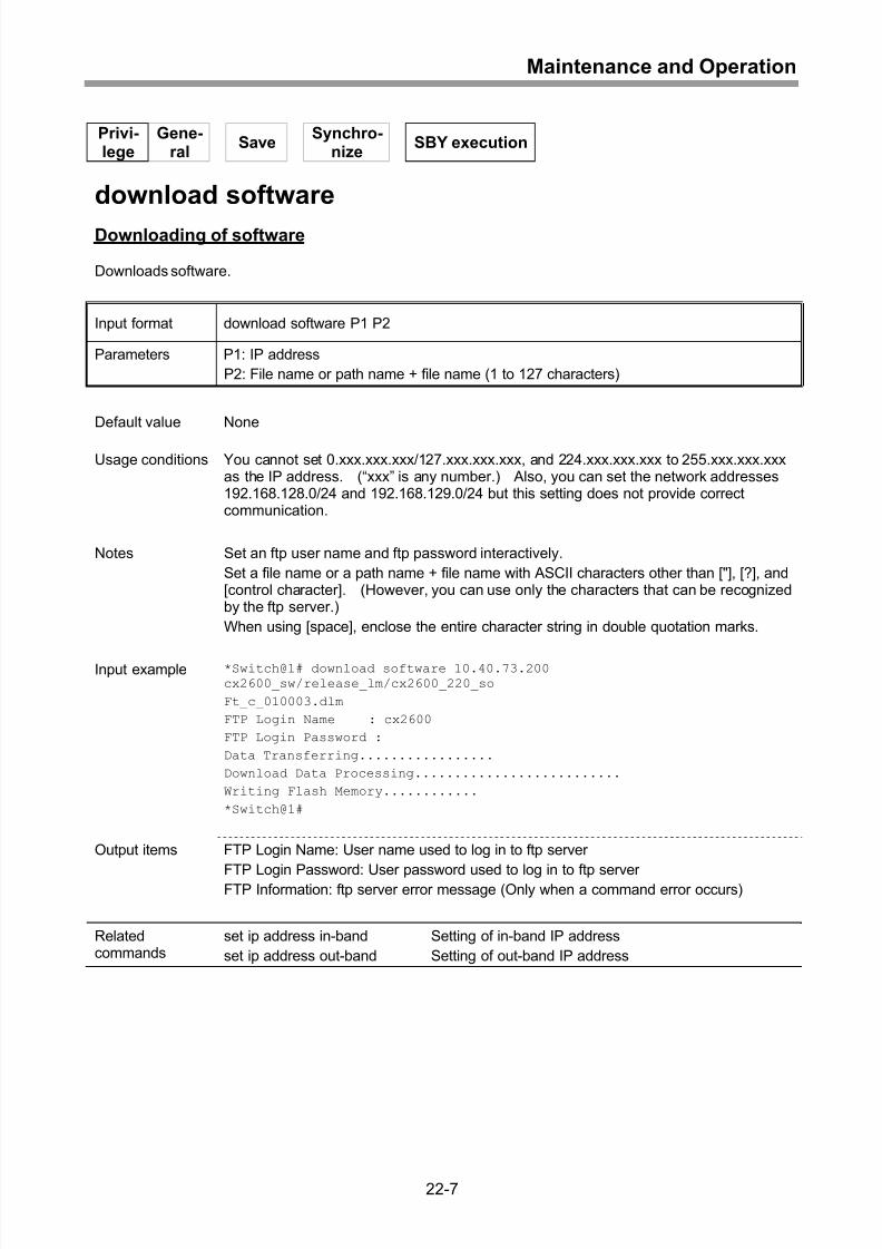
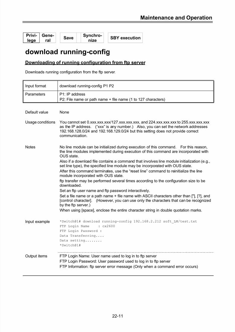
Downloading of software..........................................................................................22-7
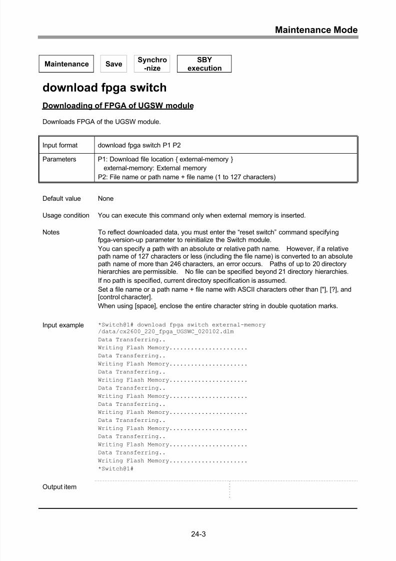
Downloading of FPGA of UGSW module.................................................................22-8
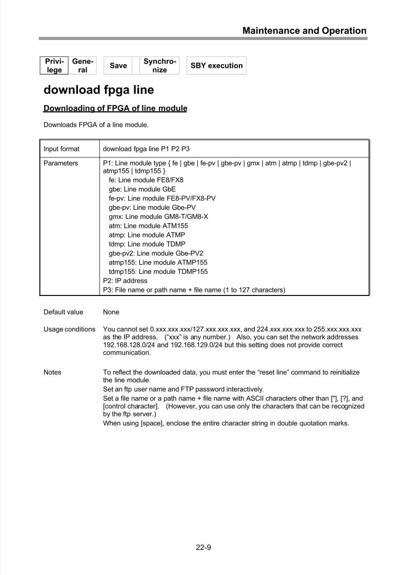
Downloading of FPGA of line module.......................................................................22-9
Downloading of running configuration from ftp server ............................................22-11
Downloading of startup configuration from ftp server .............................................22-13
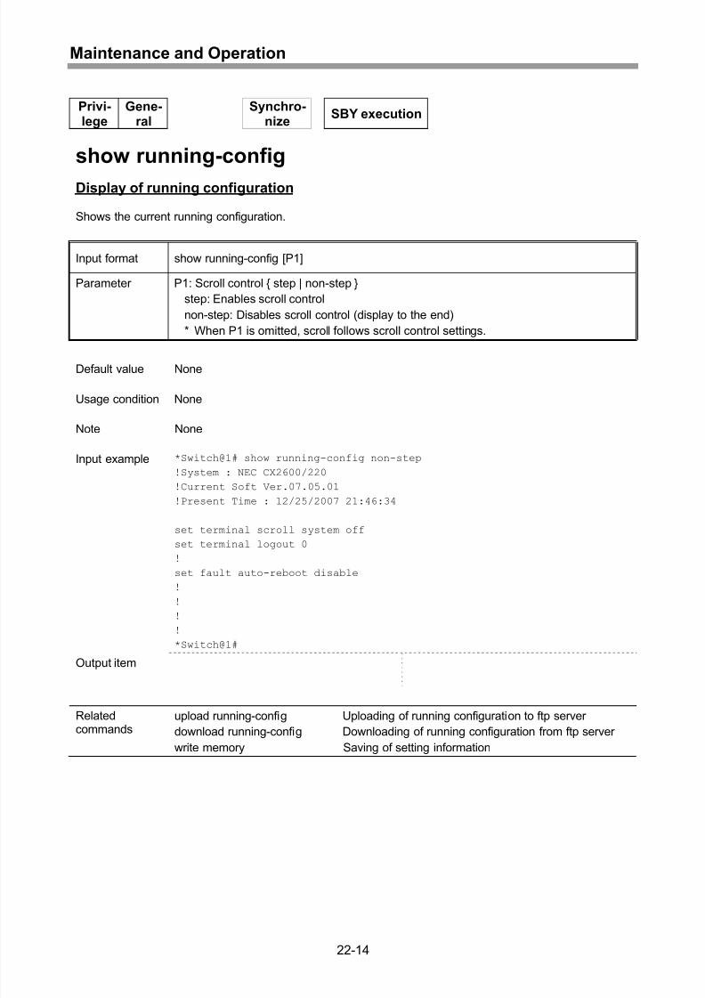
Display of running configuration .............................................................................22-14
Display of startup configuration ..............................................................................22-15
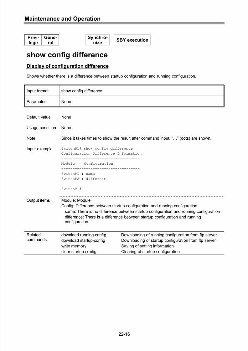
Display of configuration difference .........................................................................22-16
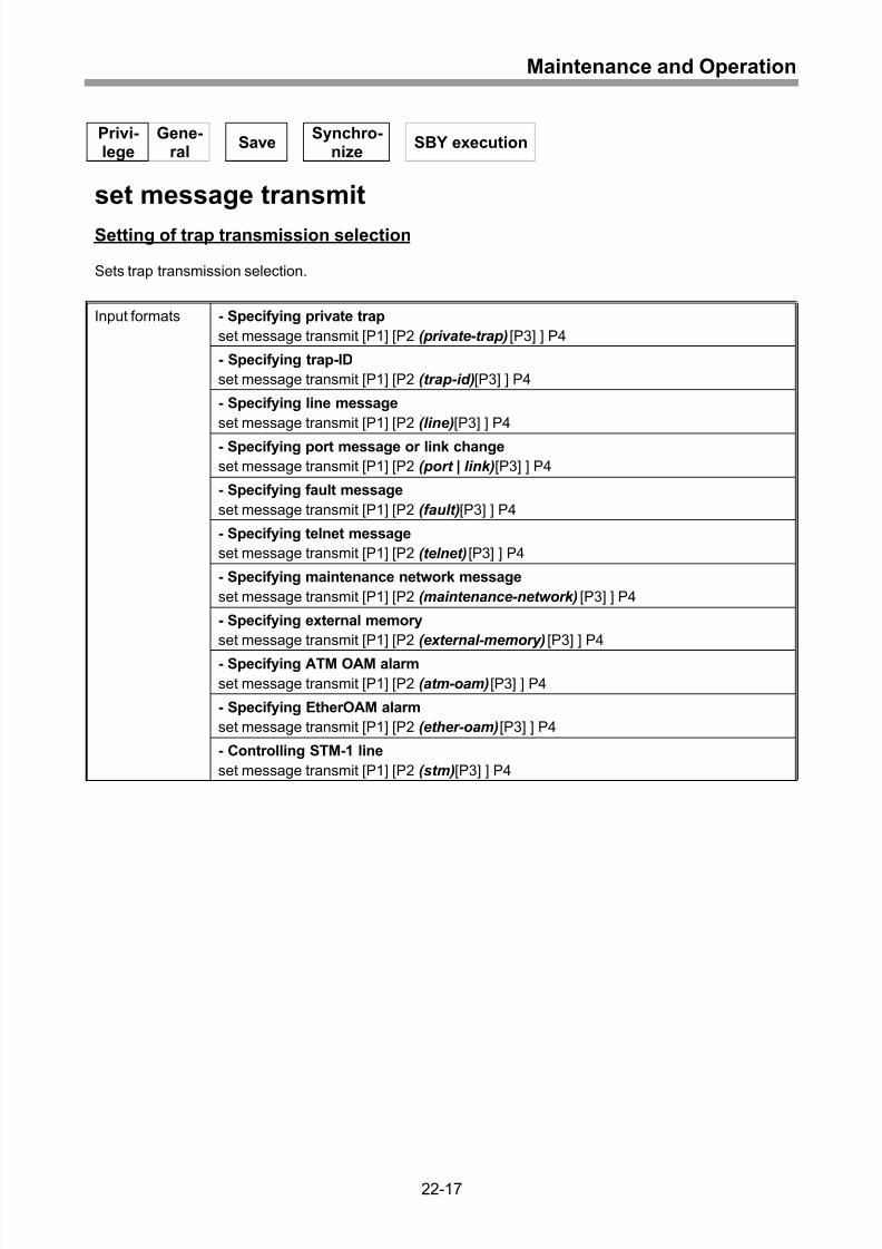
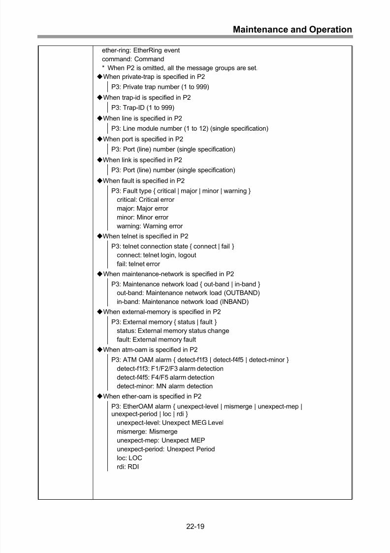
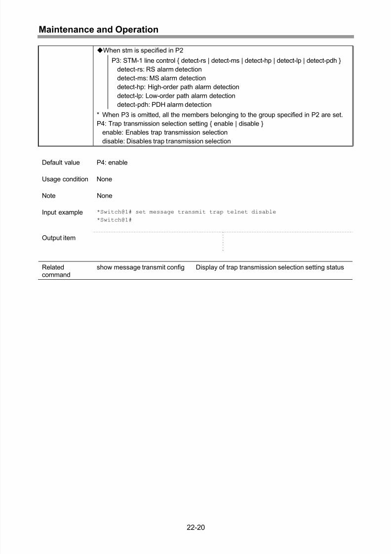
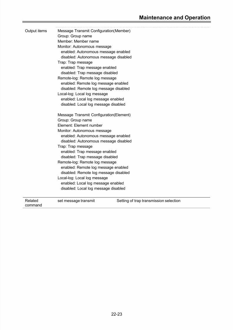
Setting of trap transmission selection.....................................................................22-17
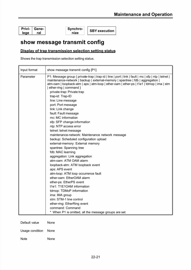
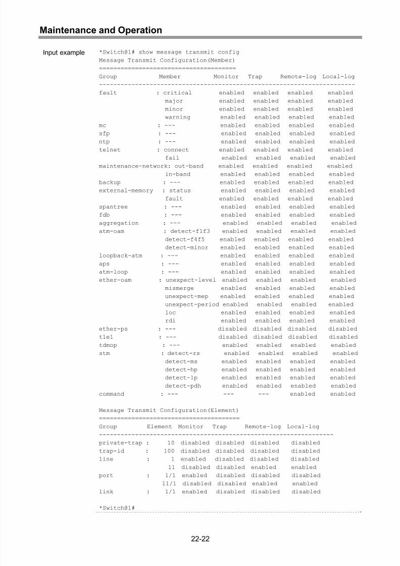
Display of trap transmission selection setting status..............................................22-21
Display of all setting information.............................................................................22-24
Saving of setting information ..................................................................................22-26
xviii
Page 23
8/21/2019 CX2600-220_Command_Reference_v7.6B_eng - Copy.pdf
http://slidepdf.com/reader/full/cx2600-220commandreferencev76beng-copypdf 23/758
Contents
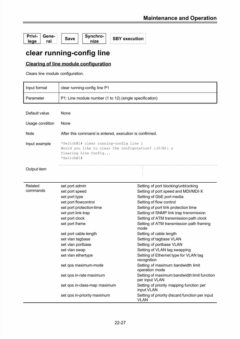
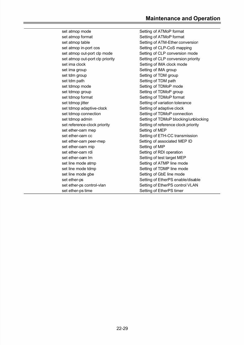
Clearing of line module configuration .....................................................................22-27
Clearing of startup configuration ............................................................................22-30
Setting of backup server.........................................................................................22-31
Clearing of backup server ......................................................................................22-32
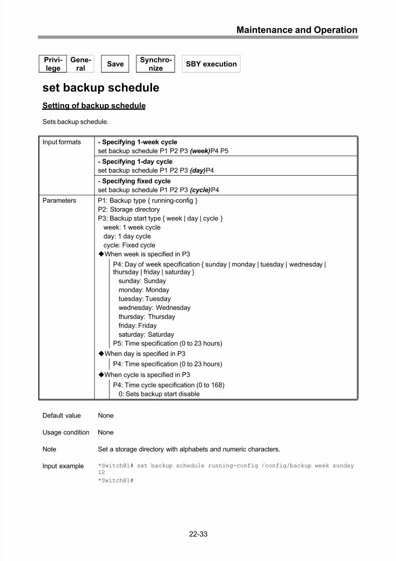
Setting of backup schedule ....................................................................................22-33
Display of backup information ................................................................................22-35
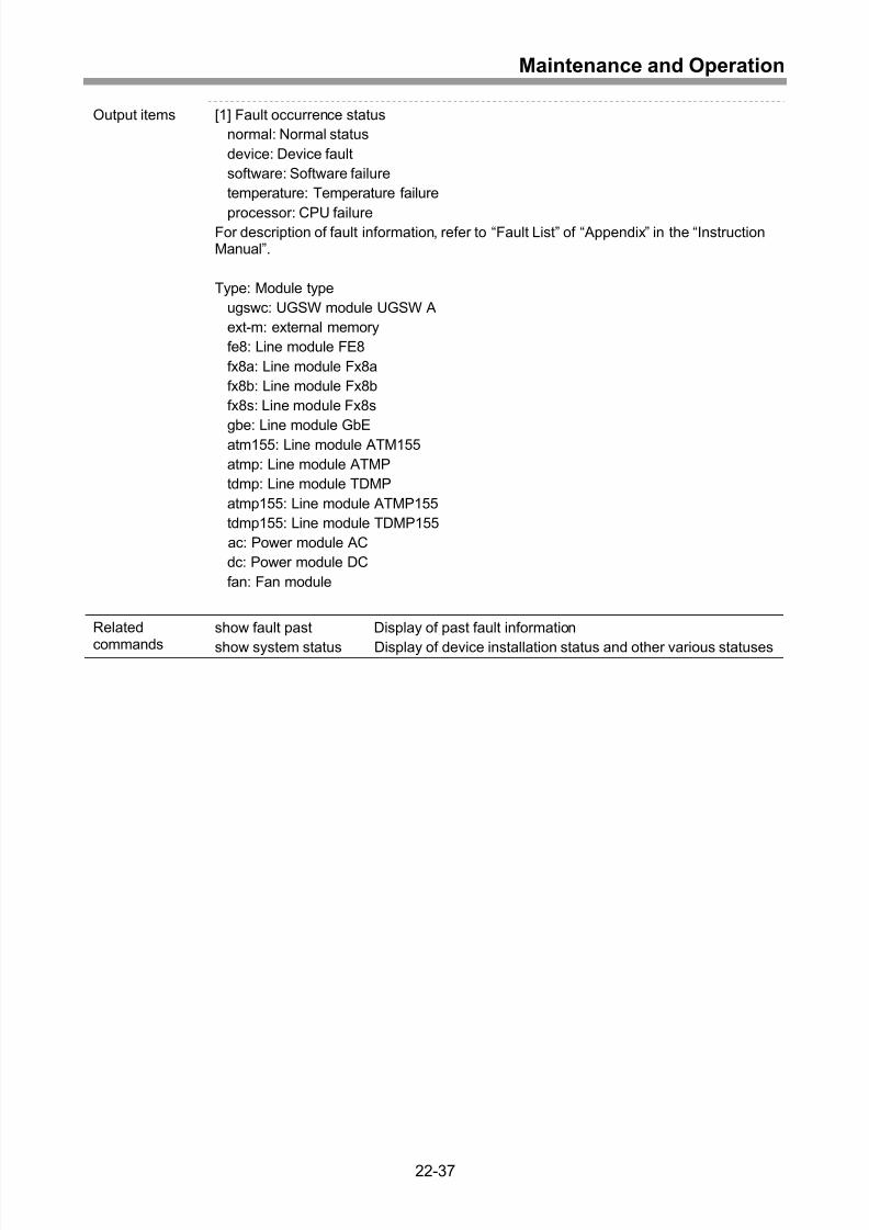
Display of current fault and alarm information ........................................................22-36
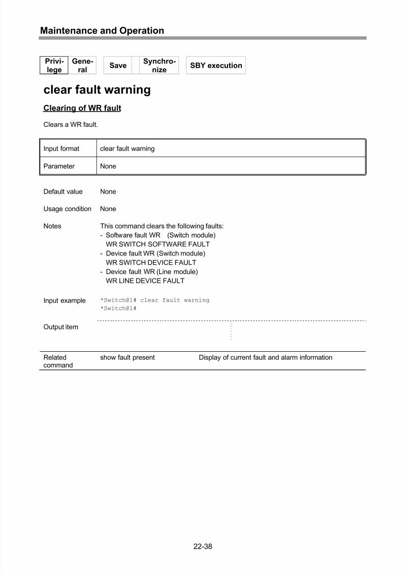
Clearing of WR fault ...............................................................................................22-38
Display of past fault information .............................................................................22-39
Clearing of past fault information............................................................................22-41
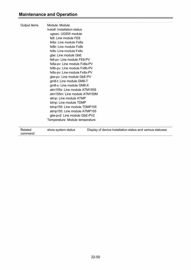
Display of device installation status and other various statuses.............................22-42
Display of bridge information for device .................................................................22-44
Display of module ID information ...........................................................................22-45
Display of various version information....................................................................22-47
Display of device temperature................................................................................22-49
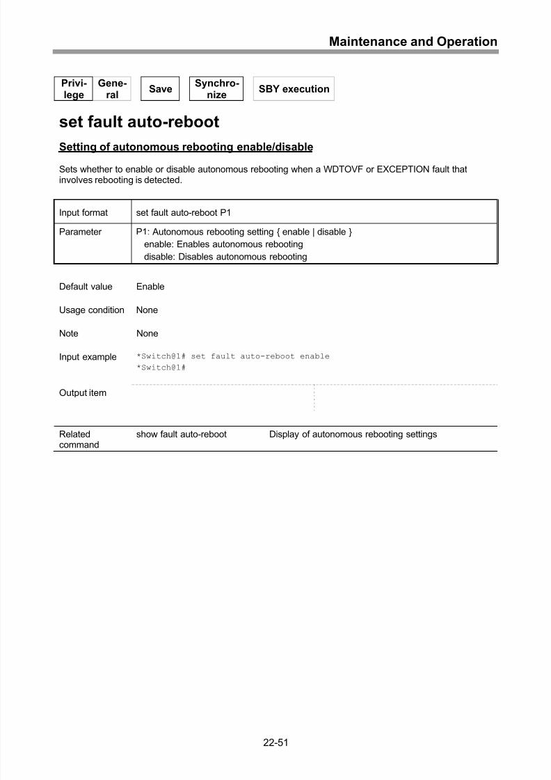
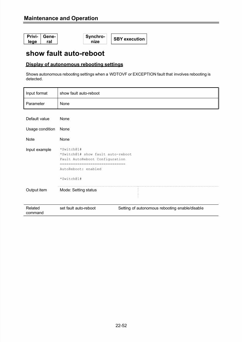
Setting of autonomous rebooting enable/disable ...................................................22-51
Display of autonomous rebooting settings..............................................................22-52
Display of CPU usage ............................................................................................22-53
Display of memory usage.......................................................................................22-55
23 Device Control ......................................................................23-1
Setting of line module type .......................................................................................23-2
Setting of TDMP line mode ......................................................................................23-3
Setting of ATMP line mode.......................................................................................23-6
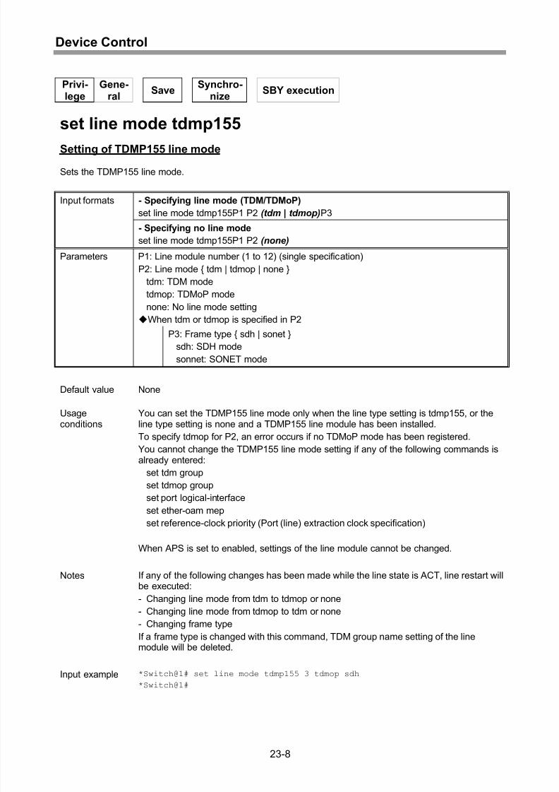
Setting of TDMP155 line mode ................................................................................23-8
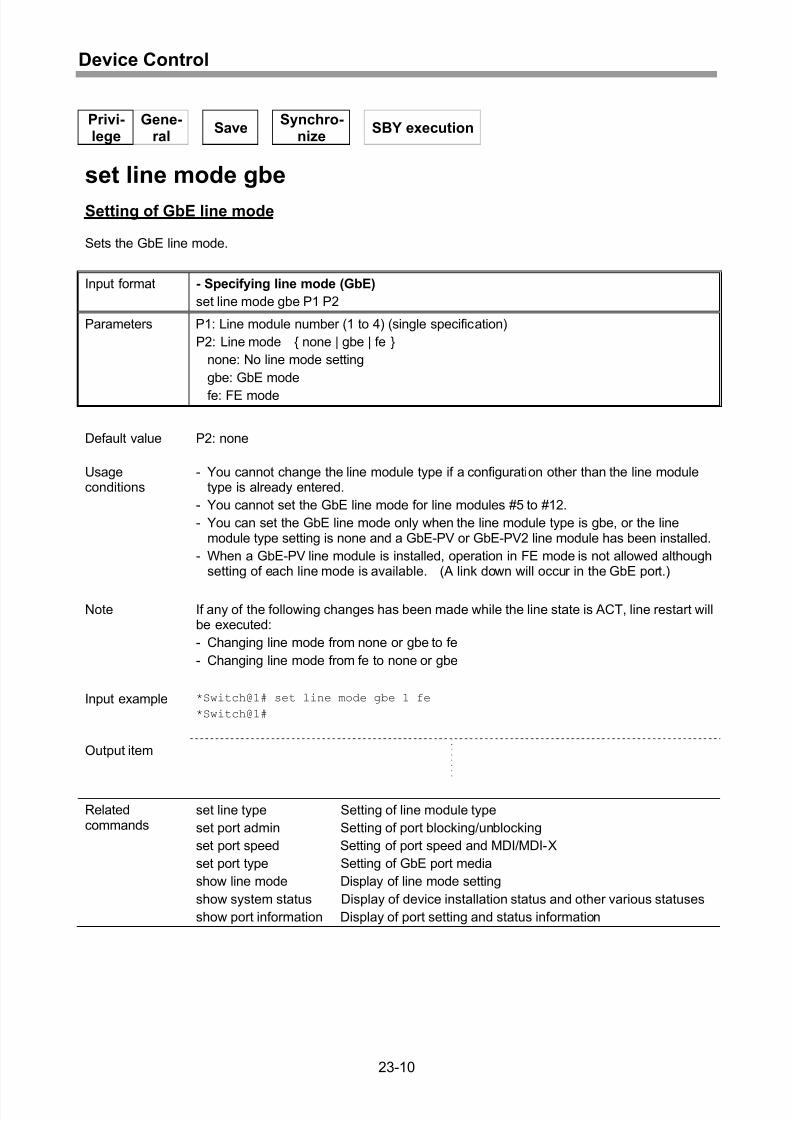
Setting of GbE line mode .......................................................................................23-10
Display of line mode setting ...................................................................................23-11
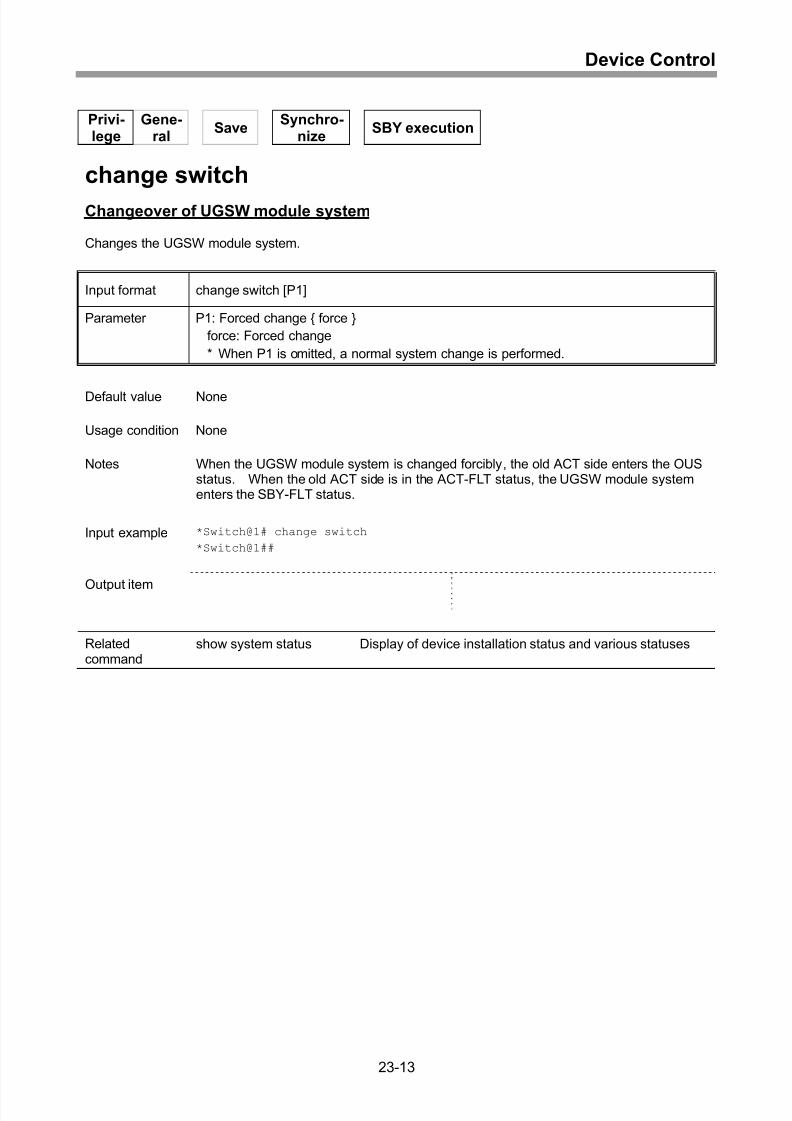
Changeover of UGSW module system...................................................................23-13
Resetting of entire device.......................................................................................23-14
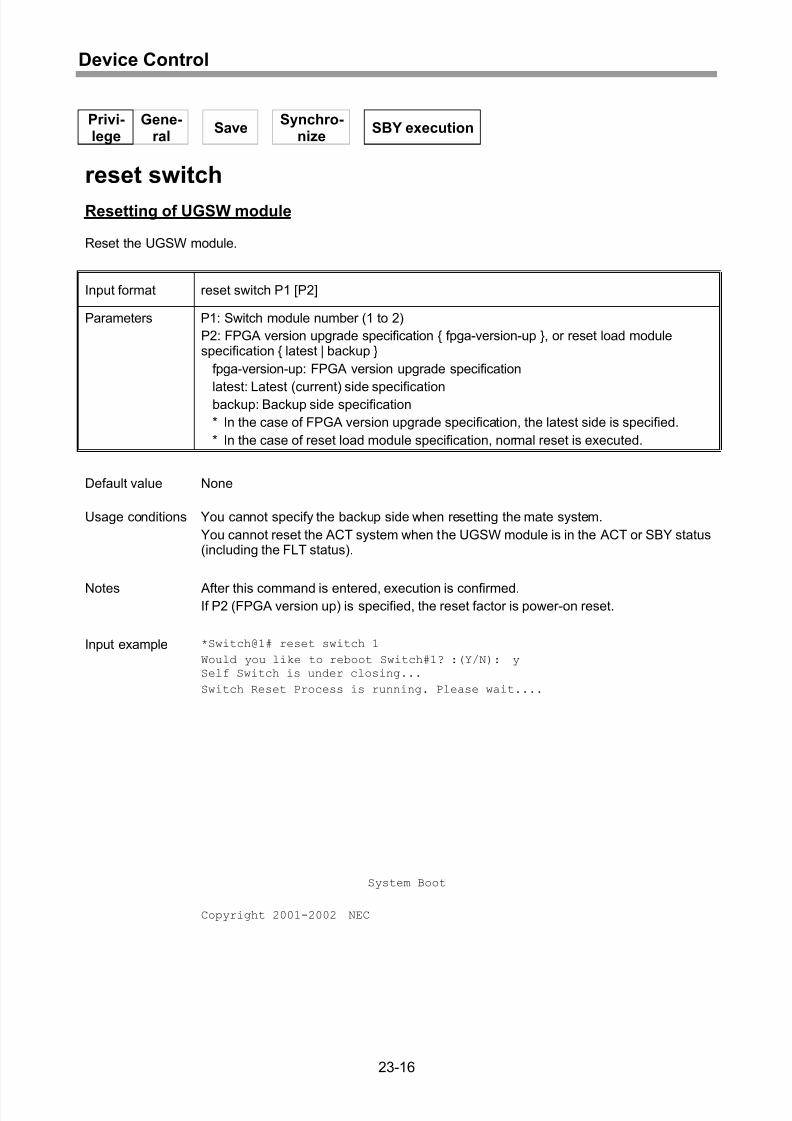
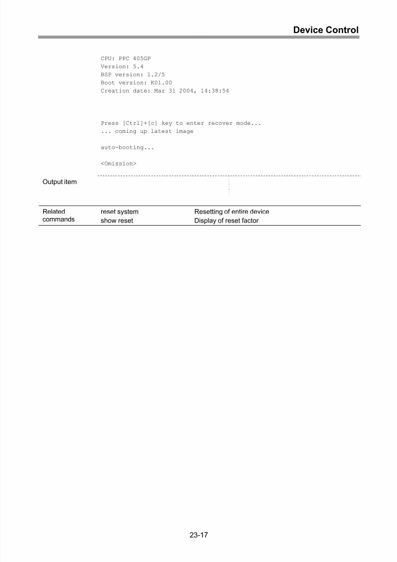
Resetting of UGSW module ...................................................................................23-16
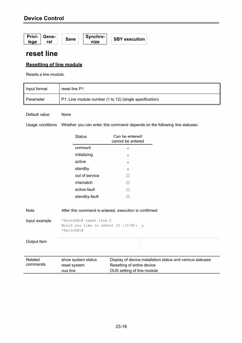
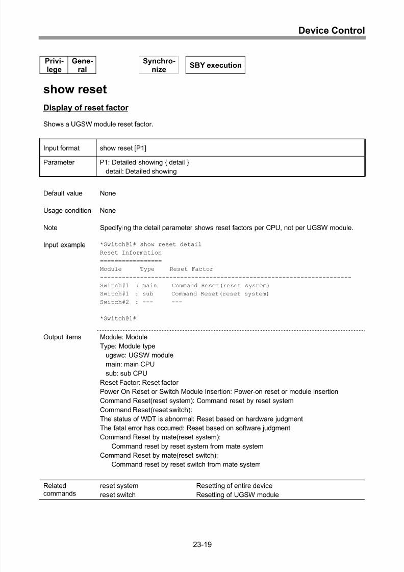
Resetting of line module.........................................................................................23-18
Display of reset factor.............................................................................................23-19
OUS setting of UGSW module ...............................................................................23-20
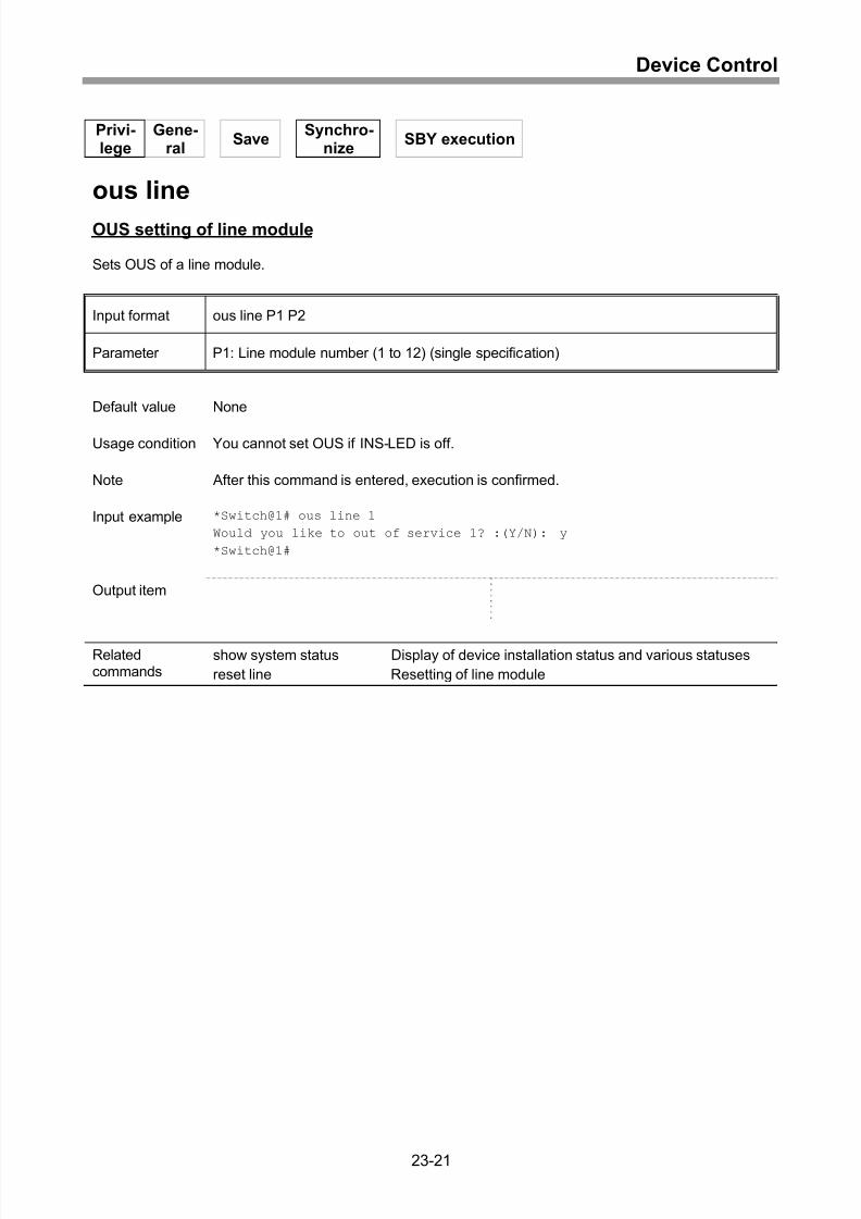
OUS setting of line module.....................................................................................23-21
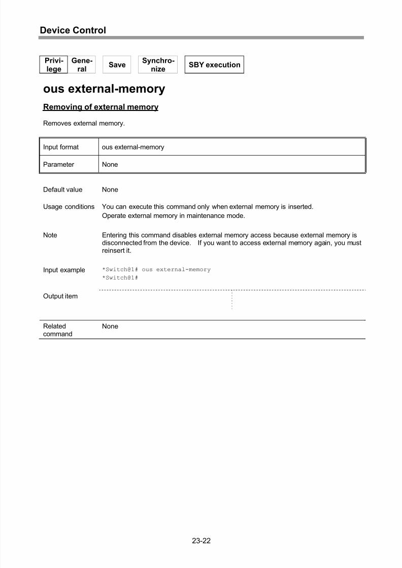
Removing of external memory ...............................................................................23-22
xix
Page 24
8/21/2019 CX2600-220_Command_Reference_v7.6B_eng - Copy.pdf
http://slidepdf.com/reader/full/cx2600-220commandreferencev76beng-copypdf 24/758
Contents
24 Maintenance Mode ...............................................................24-1
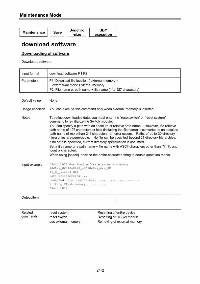
Downloading of software..........................................................................................24-2
Downloading of FPGA of UGSW module.................................................................24-3
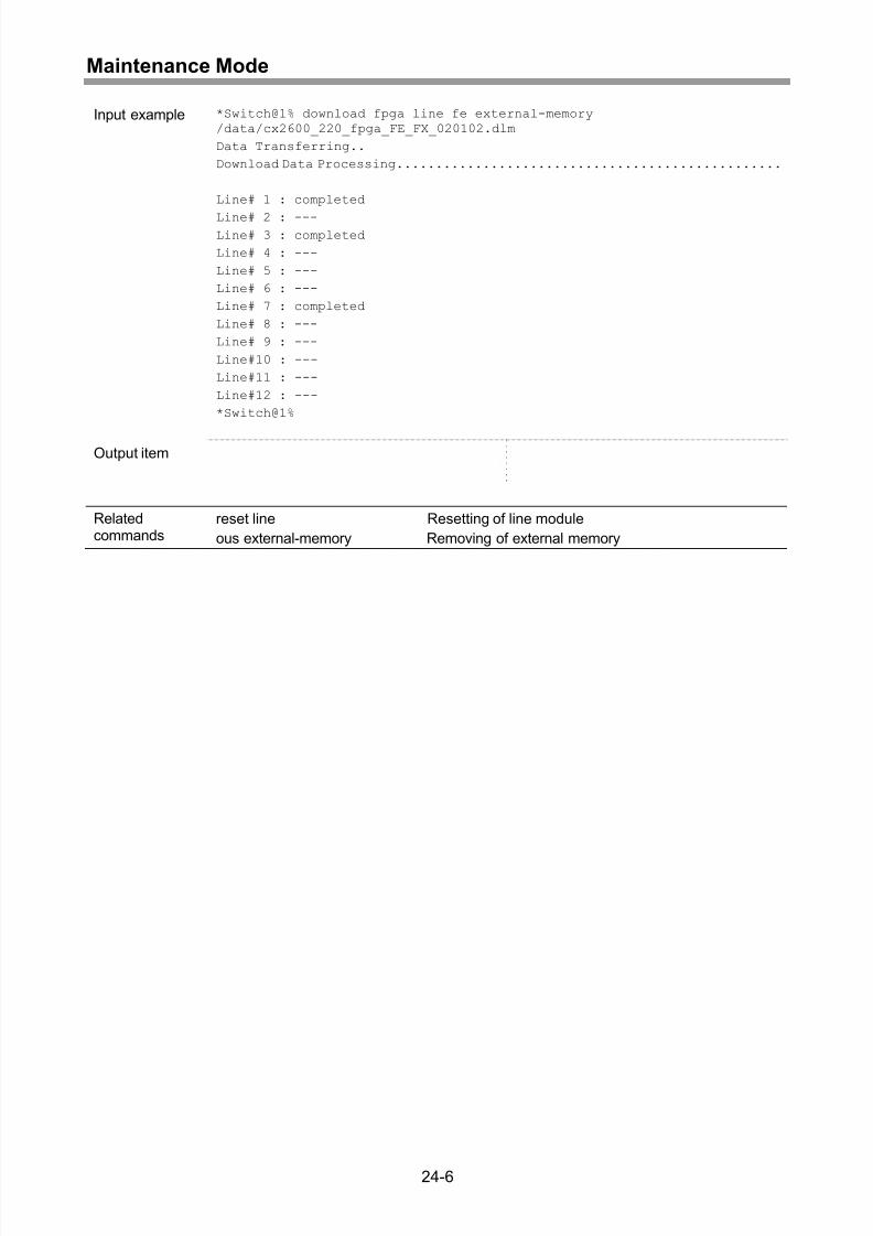
Downloading of FPGA of line module.......................................................................24-5
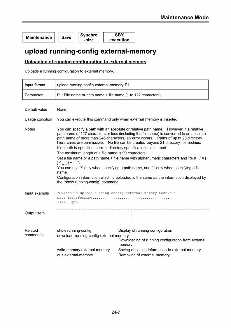
Uploading of running configuration to external memory ...........................................24-7
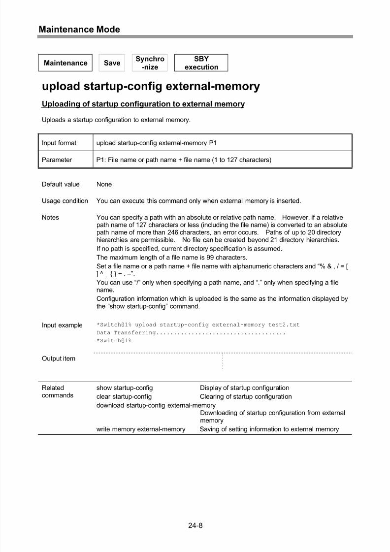
Uploading of startup configuration to external memory ............................................24-8
Uploading of system log to external memory ...........................................................24-9
Downloading of running configuration from external memory ................................24-10
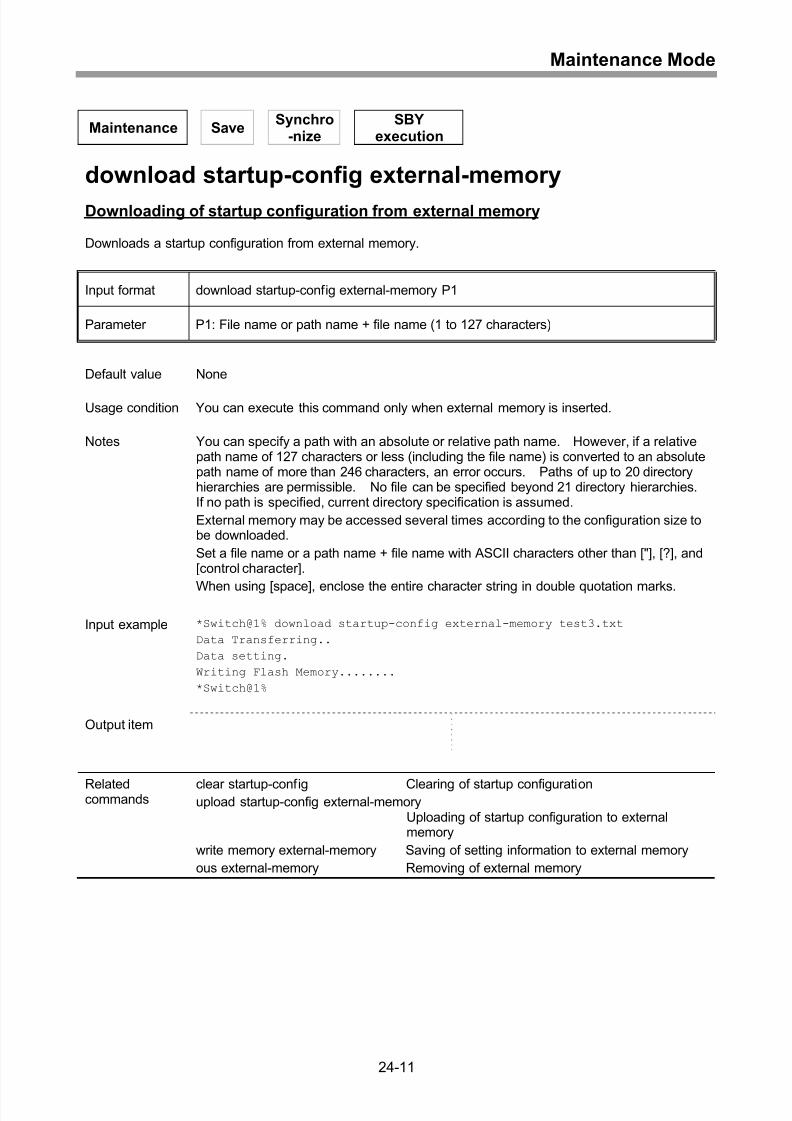
Downloading of startup configuration from external memory .................................24-11
Uploading of fault information to external memory .................................................24-12
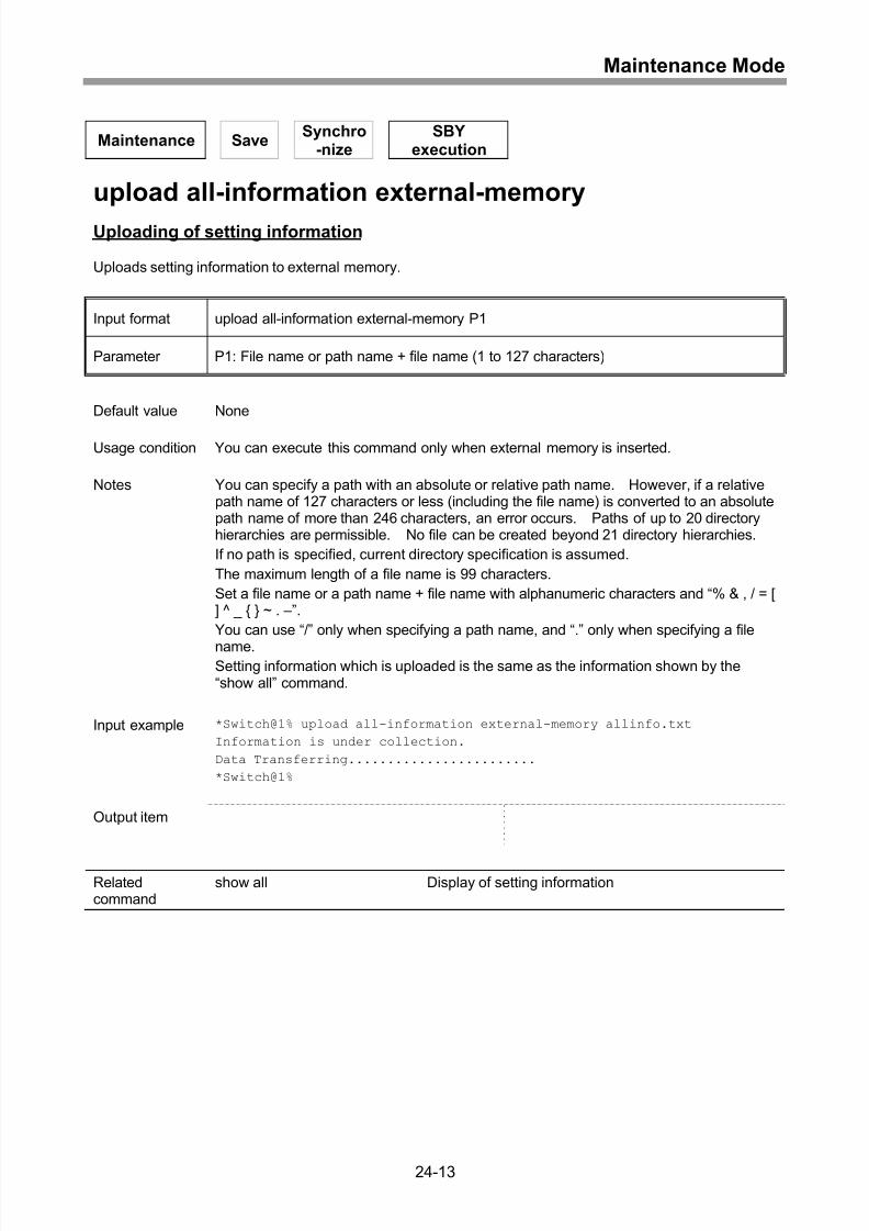
Uploading of setting information.............................................................................24-13
Saving of setting status to external memory...........................................................24-14
Switch from maintenance mode to privileged mode...............................................24-15
Display of list of contents in directory .....................................................................24-16
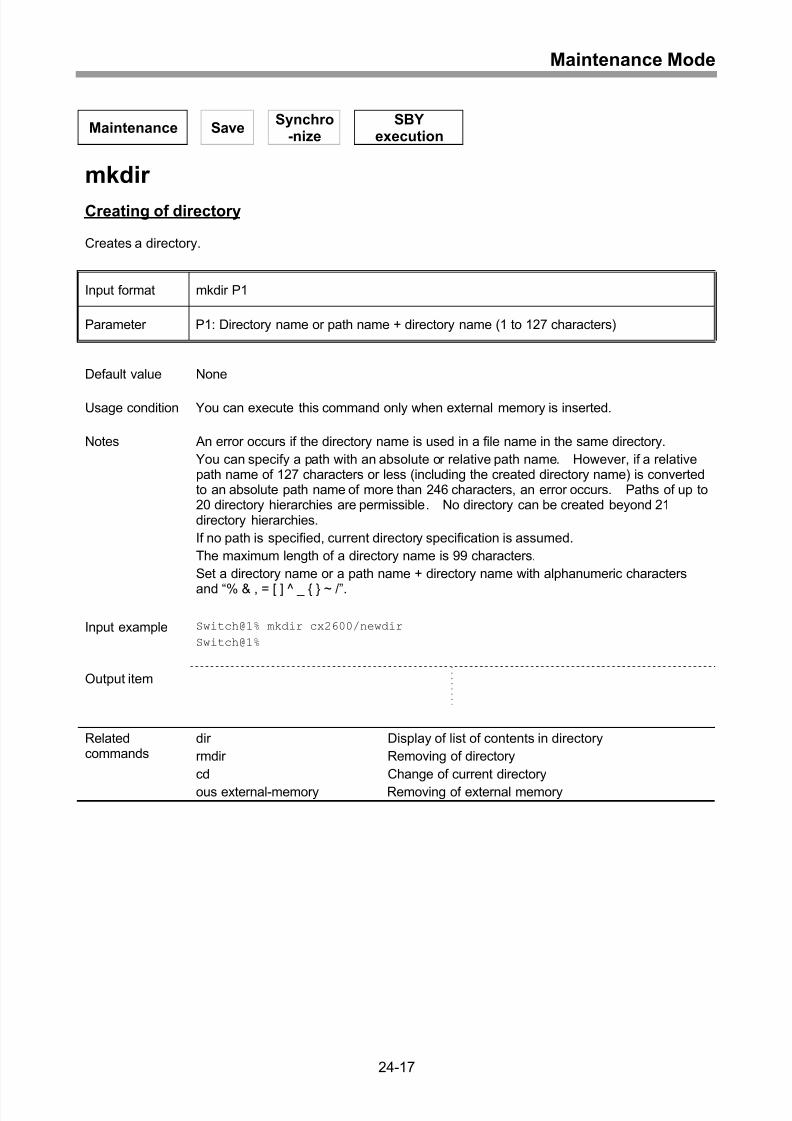
Creating of directory...............................................................................................24-17
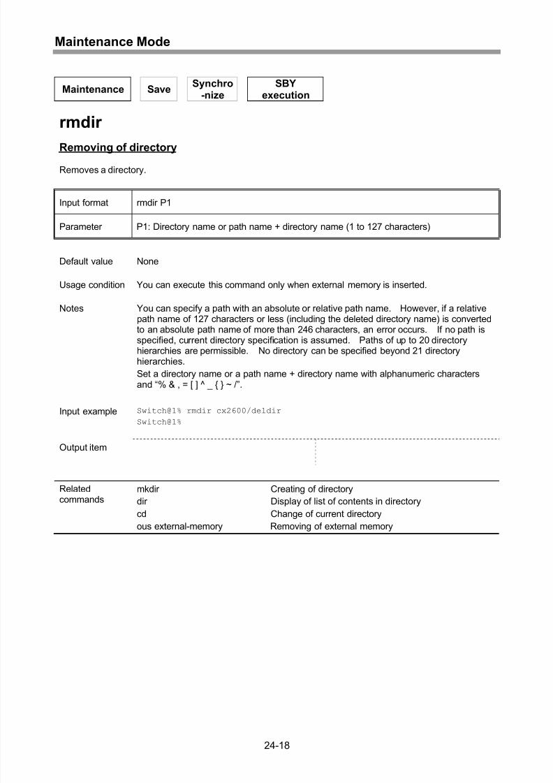
Removing of directory ............................................................................................24-18
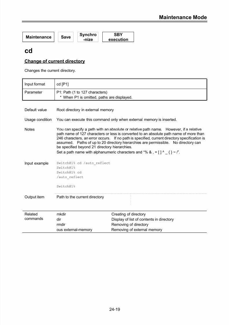
Change of current directory....................................................................................24-19
Copying file ............................................................................................................24-20
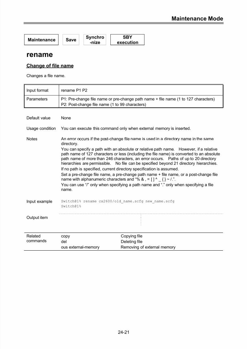
Change of file name ...............................................................................................24-21
Deleting file ............................................................................................................24-22
Removing of external memory ...............................................................................24-23
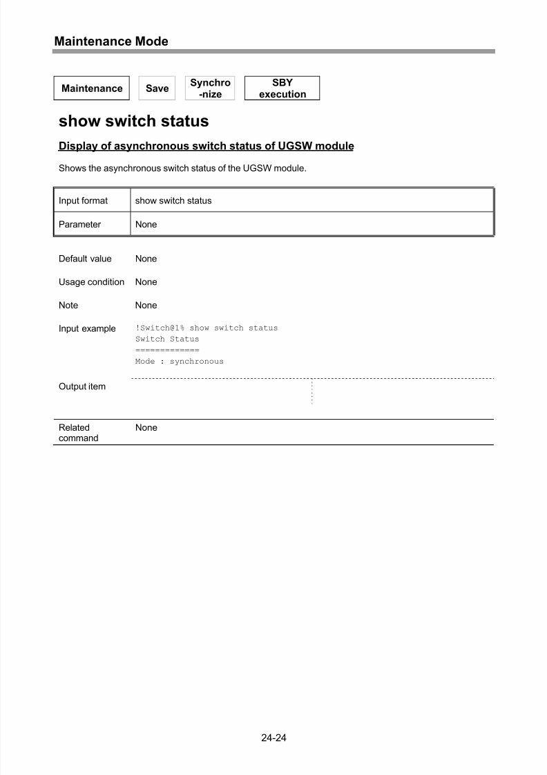
Display of asynchronous switch status of UGSW module......................................24-24
25 Appendix ...............................................................................25-1
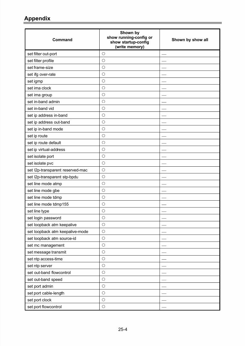
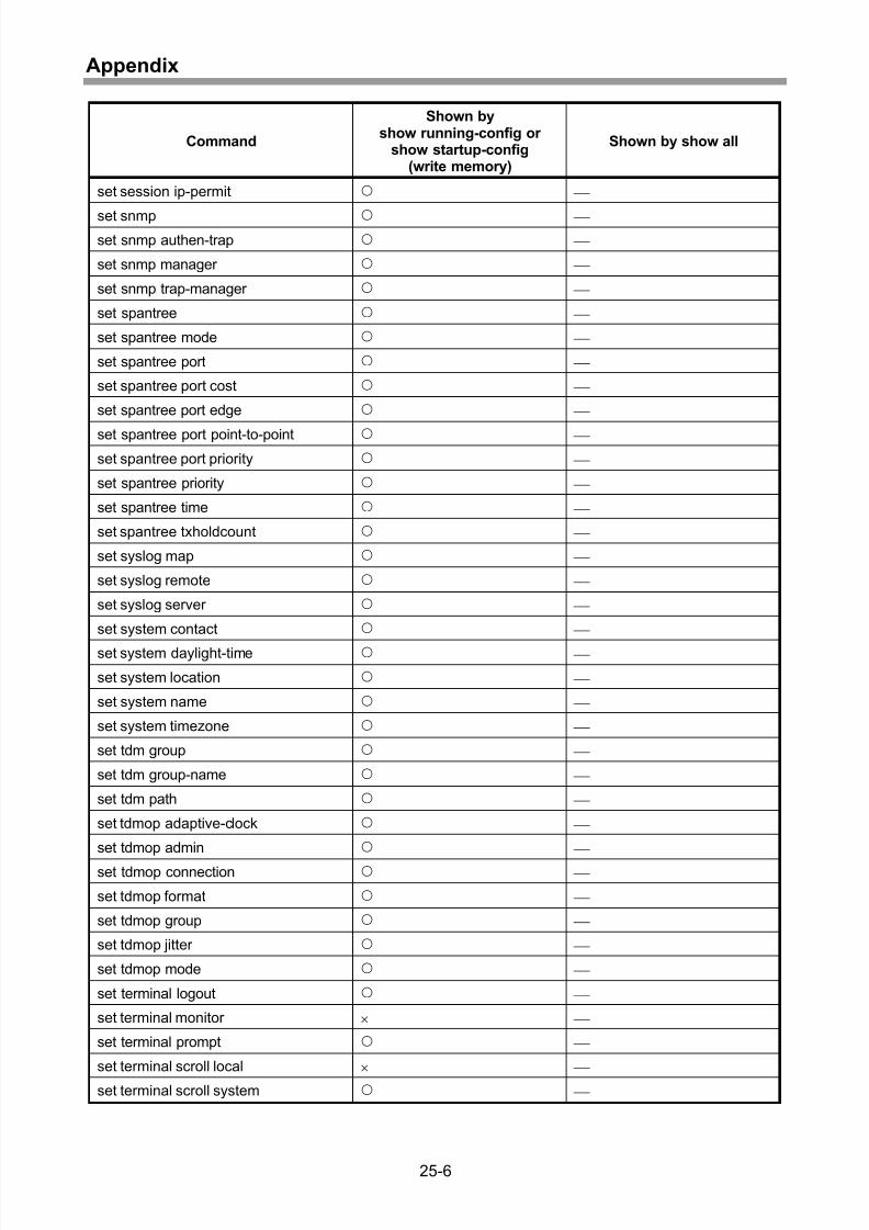
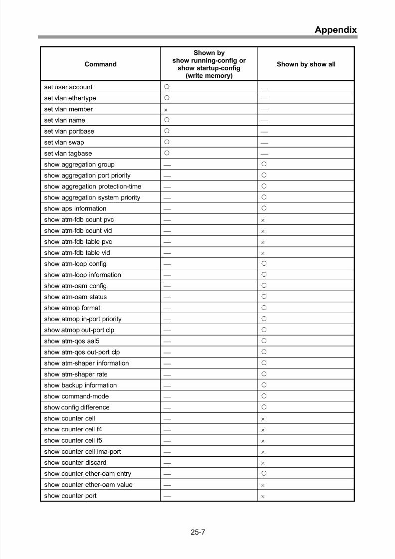
Appendix 1 Commands shown by configuration display and show all ...................25-2
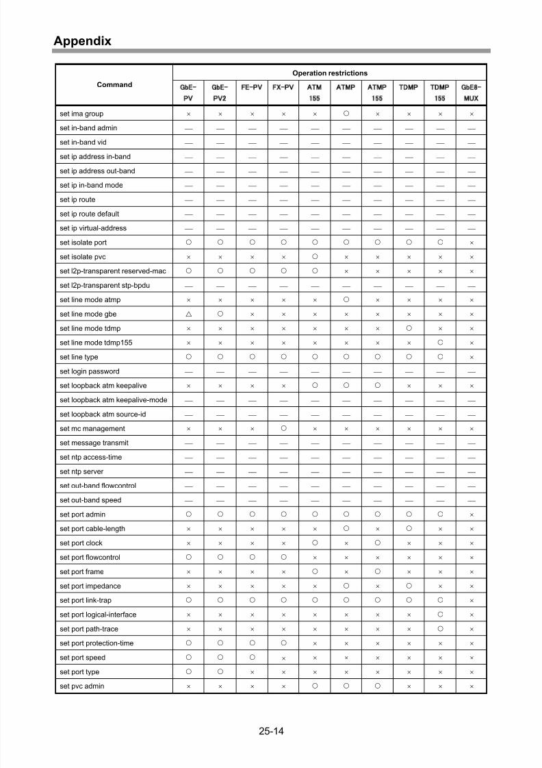
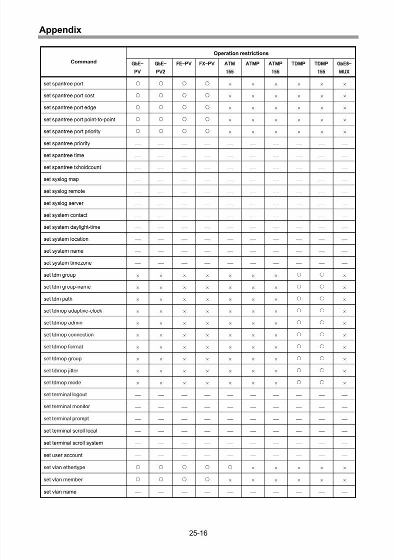
Appendix 2 Line module type conditions .............................................................25-12
Index ..................................................................................... Index-1
xx
Page 25
8/21/2019 CX2600-220_Command_Reference_v7.6B_eng - Copy.pdf
http://slidepdf.com/reader/full/cx2600-220commandreferencev76beng-copypdf 25/758
Operation Modes
1 Operation Modes
1-1
Page 26
8/21/2019 CX2600-220_Command_Reference_v7.6B_eng - Copy.pdf
http://slidepdf.com/reader/full/cx2600-220commandreferencev76beng-copypdf 26/758
Operation Modes
Privi-lege
Gene-ral
Save Synchro-
nizeSBY execution
exit
Logout
This command is used for logout from CLI.
Input format exit
Parameter None
Default value None
Usage condition None
Note None
Input example *Switch@1# exit
Output item
Related
commands
enable Switch from general mode to privileged mode
disable Switch from privileged mode to general mode
1-2
Page 27
8/21/2019 CX2600-220_Command_Reference_v7.6B_eng - Copy.pdf
http://slidepdf.com/reader/full/cx2600-220commandreferencev76beng-copypdf 27/758
Operation Modes
Privi-lege
Gene-ral
Save Synchro-
nizeSBY execution
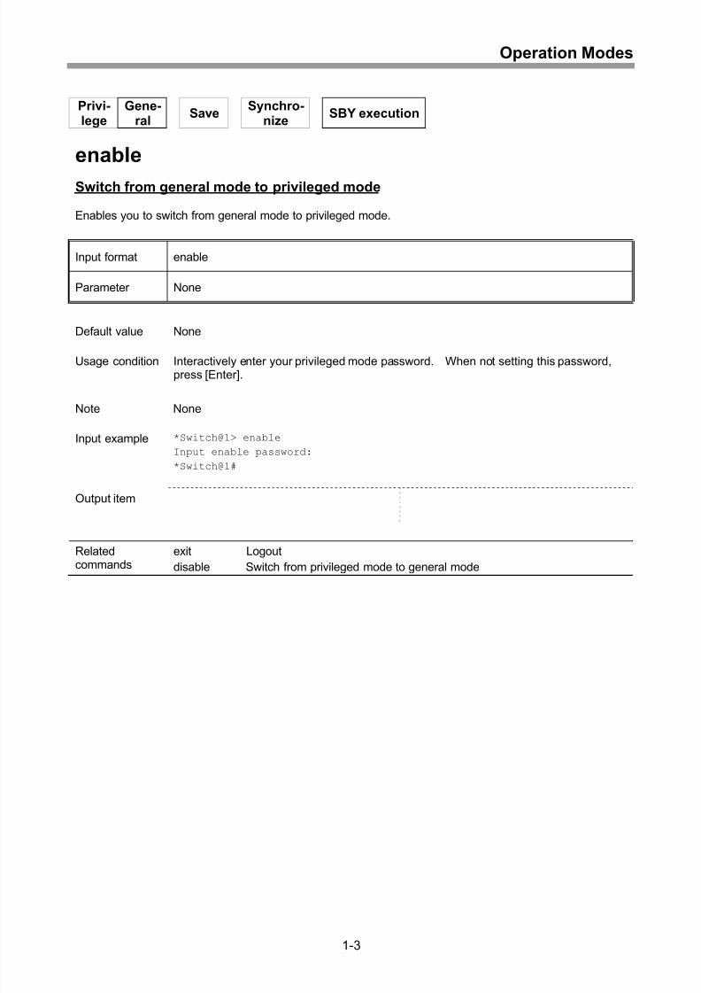
enable
Switch from general mode to privileged mode
Enables you to switch from general mode to privileged mode.
Input format enable
Parameter None
Default value None
Usage condition Interactively enter your privileged mode password. When not setting this password,press [Enter].
Note None
Input example *Switch@1> enable
Input enable password:
*Switch@1#
Output item
Relatedcommands
exit Logout
disable Switch from privileged mode to general mode
1-3
Page 28
8/21/2019 CX2600-220_Command_Reference_v7.6B_eng - Copy.pdf
http://slidepdf.com/reader/full/cx2600-220commandreferencev76beng-copypdf 28/758
Operation Modes
Privi-lege
Gene-ral
Save Synchro-
nizeSBY execution
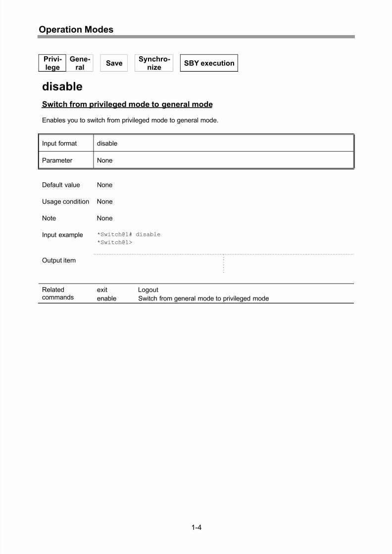
disable
Switch from privileged mode to general mode
Enables you to switch from privileged mode to general mode.
Input format disable
Parameter None
Default value None
Usage condition None
Note None
Input example *Switch@1# disable
*Switch@1>
Output item
Relatedcommands
exit Logoutenable Switch from general mode to privileged mode
1-4
Page 29
8/21/2019 CX2600-220_Command_Reference_v7.6B_eng - Copy.pdf
http://slidepdf.com/reader/full/cx2600-220commandreferencev76beng-copypdf 29/758
Operation Modes
Privi-lege
Gene-ral
SaveSynchro-
nizeSBY execution
maintenance
Switch from privileged mode to maintenance mode
Enables you to switch from privileged mode to maintenance mode.
Input format maintenance
Parameter None
Default value None
Usage condition If another session is in maintenance mode, you cannot switch from privileged mode tomaintenance mode.
Note None
Input example *Switch@1# maintenance
*Switch@1%
Output item
Relatedcommand
end Switch from maintenance mode to privileged mode
1-5
Page 30
8/21/2019 CX2600-220_Command_Reference_v7.6B_eng - Copy.pdf
http://slidepdf.com/reader/full/cx2600-220commandreferencev76beng-copypdf 30/758
Operation Modes
Privi-lege
Gene-ral
SaveSynchro-
nizeSBY execution
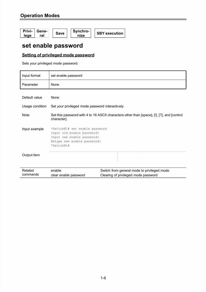
set enable password
Setting of privileged mode password
Sets your privileged mode password.
Input format set enable password
Parameter None
Default value None
Usage condition Set your privileged mode password interactively.
Note Set this password with 4 to 16 ASCII characters other than [space], [!], [?], and [controlcharacter].
Input example *Switch@1# set enable password
Input old enable password:
Input new enable password:
Retype new enable password:
*Switch@1#
Output item
Relatedcommands
enable Switch from general mode to privileged mode
clear enable password Clearing of privileged mode password
1-6
Page 31
8/21/2019 CX2600-220_Command_Reference_v7.6B_eng - Copy.pdf
http://slidepdf.com/reader/full/cx2600-220commandreferencev76beng-copypdf 31/758
Operation Modes
Privi-lege
Gene-ral
SaveSynchro-
nizeSBY execution
clear enable password
Clearing of privileged mode password
Clears your privileged mode password.
Input format clear enable password
Parameter None
Default value None
Usage condition Clear your privileged mode password interactively.
Note Set this password with 4 to 16 ASCII characters other than [space], [!], [?], and [controlcharacter].
Input example *Switch@1# clear enable password
Input old password:
*Switch@1#
Output item
Relatedcommands
enable Switch from general mode to privileged mode
set enable password Setting of privileged mode password
1-7
Page 32
8/21/2019 CX2600-220_Command_Reference_v7.6B_eng - Copy.pdf
http://slidepdf.com/reader/full/cx2600-220commandreferencev76beng-copypdf 32/758
Operation Modes
Privi-lege
Gene-ral
SaveSynchro-
nizeSBY execution
set login password
Setting of login password
Sets your login password.
Input format set login password
Parameter None
Default value None
Usage condition Set your login password interactively.
Note Set this password with 4 to 16 ASCII characters other than [space], [!], [?], and [controlcharacter].
Input example *Switch@1# set login password
Input old password:
Input new password:
Retype new password:
*Switch@1#
Output item
Relatedcommands
exit Logout
clear login password Clearing of login password
1-8
Page 33
8/21/2019 CX2600-220_Command_Reference_v7.6B_eng - Copy.pdf
http://slidepdf.com/reader/full/cx2600-220commandreferencev76beng-copypdf 33/758
Operation Modes
Privi-lege
Gene-ral
SaveSynchro-
nizeSBY execution
clear login password
Clearing of login password
Clears your login password.
Input format clear login password
Parameter None
Default value None
Usage condition Clear your login password interactively.
Note Set this password with 4 to 16 ASCII characters other than [space], [!], [?], and [controlcharacter].
Input example *Switch@1# clear login password
Input old password:
*Switch@1#
Output item
Relatedcommands
exit Logout
set login password Setting of login password
1-9
Page 34
8/21/2019 CX2600-220_Command_Reference_v7.6B_eng - Copy.pdf
http://slidepdf.com/reader/full/cx2600-220commandreferencev76beng-copypdf 34/758
Operation Modes
Privi-lege
Gene-ral
SaveSynchro-
nizeSBY execution
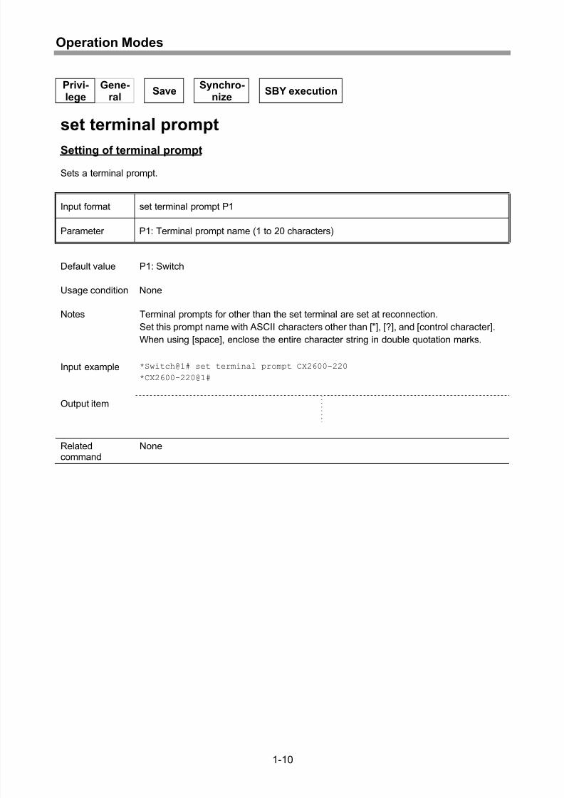
set terminal prompt
Setting of terminal prompt
Sets a terminal prompt.
Input format set terminal prompt P1
Parameter P1: Terminal prompt name (1 to 20 characters)
Default value P1: Switch
Usage condition None
Notes Terminal prompts for other than the set terminal are set at reconnection.
Set this prompt name with ASCII characters other than ["], [?], and [control character].
When using [space], enclose the entire character string in double quotation marks.
Input example *Switch@1# set terminal prompt CX2600-220
*CX2600-220@1#
Output item
Relatedcommand
None
1-10
Page 35
8/21/2019 CX2600-220_Command_Reference_v7.6B_eng - Copy.pdf
http://slidepdf.com/reader/full/cx2600-220commandreferencev76beng-copypdf 35/758
Operation Modes
Privi-lege
Gene-ral
SaveSynchro-
nizeSBY execution
set terminal scroll system
Setting of scroll control defaults
Sets scroll control defaults.
- Specifying that screen scroll stop is off
set terminal scroll system P1 (off)
Input Formats
- Specifying that screen scroll stop is on
set terminal scroll system [P1 (on) ] [P2]
Parameters P1: Scroll control { off | on }
off: Screen scroll stop is off
on: Screen scroll stop is on
* When P1 is omitted, on is assumed.
When on is specified in P1.
P2: Number of scroll lines (1 to 99)
* When P2 is omitted, 22 is assumed.
Default value P1: on
P2: 22
Usage condition None
Note Scroll control defaults are set in all terminals at reconnection.
Input example *Switch@1# set terminal scroll system on
*Switch@1#
Output item
Relatedcommand
show terminal config Display of terminal information
1-11
Page 36
8/21/2019 CX2600-220_Command_Reference_v7.6B_eng - Copy.pdf
http://slidepdf.com/reader/full/cx2600-220commandreferencev76beng-copypdf 36/758
Operation Modes
Privi-lege
Gene-ral
Save Synchro-
nizeSBY execution
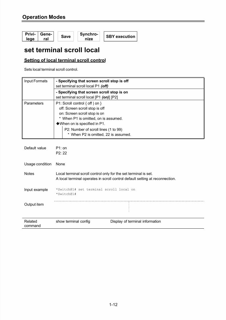
set terminal scroll local
Setting of local terminal scroll control
Sets local terminal scroll control.
- Specifying that screen scroll stop is off
set terminal scroll local P1 (off)
Input Formats
- Specifying that screen scroll stop is on
set terminal scroll local [P1 (on) ] [P2]
Parameters P1: Scroll control { off | on }
off: Screen scroll stop is off
on: Screen scroll stop is on
* When P1 is omitted, on is assumed.
When on is specified in P1.
P2: Number of scroll lines (1 to 99)
* When P2 is omitted, 22 is assumed.
Default value P1: on
P2: 22
Usage condition None
Notes Local terminal scroll control only for the set terminal is set.
A local terminal operates in scroll control default setting at reconnection.
Input example *Switch@1# set terminal scroll local on
*Switch@1#
Output item
Relatedcommand
show terminal config Display of terminal information
1-12
Page 37
8/21/2019 CX2600-220_Command_Reference_v7.6B_eng - Copy.pdf
http://slidepdf.com/reader/full/cx2600-220commandreferencev76beng-copypdf 37/758
Operation Modes
Privi-lege
Gene-ral
Save Synchro-
nizeSBY execution
set terminal monitor
Setting of autonomous message output
Sets autonomous message output.
Input format set terminal monitor P1
Parameter P1: Autonomous message control { enable | disable }
enable: Enables autonomous message output
disable: Disables autonomous message output
Default values P1: [RS-232C] enable
[telnet] disable
Usage condition None
Notes Autonomous message output is suppressed during command execution.
Terminals operate by default at reconnection.
Input example *Switch@1# set terminal monitor enable
*Switch@1#
Output item
Relatedcommand
show terminal config Display of terminal information
1-13
Page 38
8/21/2019 CX2600-220_Command_Reference_v7.6B_eng - Copy.pdf
http://slidepdf.com/reader/full/cx2600-220commandreferencev76beng-copypdf 38/758
Operation Modes
Privi-lege
Gene-ral
SaveSynchro-
nizeSBY execution
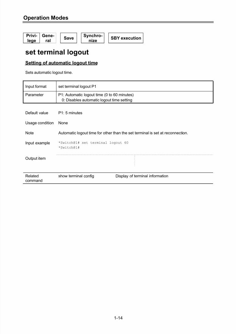
set terminal logout
Setting of automatic logout time
Sets automatic logout time.
Input format set terminal logout P1
Parameter P1: Automatic logout time (0 to 60 minutes)
0: Disables automatic logout time setting
Default value P1: 5 minutes
Usage condition None
Note Automatic logout time for other than the set terminal is set at reconnection.
Input example *Switch@1# set terminal logout 60
*Switch@1#
Output item
Relatedcommand
show terminal config Display of terminal information
1-14
Page 39
8/21/2019 CX2600-220_Command_Reference_v7.6B_eng - Copy.pdf
http://slidepdf.com/reader/full/cx2600-220commandreferencev76beng-copypdf 39/758
Operation Modes
Privi-lege
Gene-ral
Synchro-nize
SBY execution
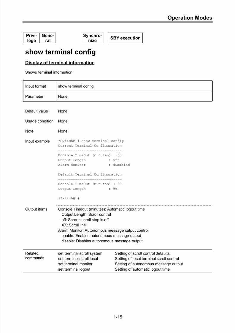
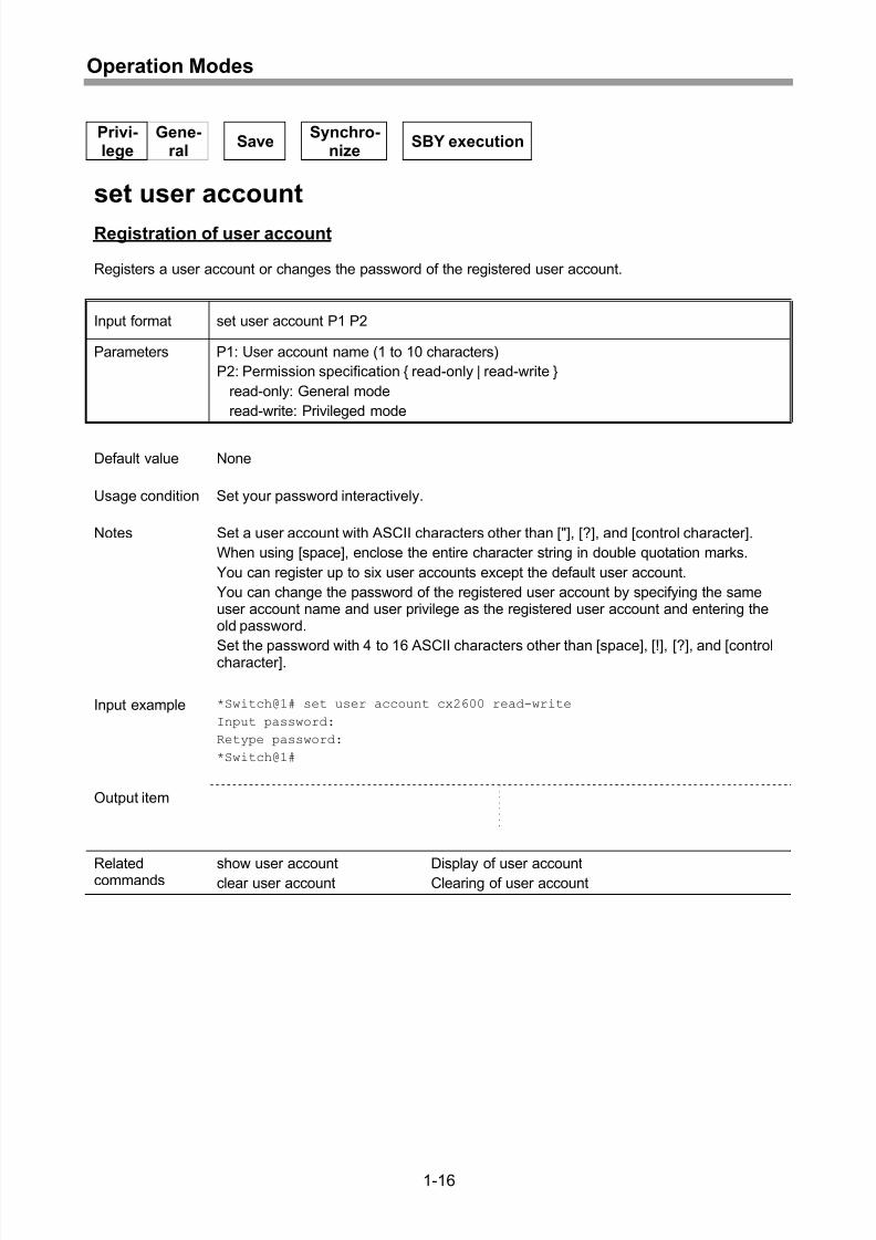
show terminal config
Display of terminal information
Shows terminal information.
Input format show terminal config
Parameter None
Default value None
Usage condition None
Note None
Input example *Switch@1# show terminal config
Current Terminal Configuration
==============================
Console TimeOut (minutes) : 60
Output Length : off
Alarm Monitor : disabled
Default Terminal Configuration==============================
Console TimeOut (minutes) : 60
Output Length : 99
*Switch@1#
Output items Console Timeout (minutes): Automatic logout time
Output Length: Scroll control
off: Screen scroll stop is off
XX: Scroll line
Alarm Monitor: Autonomous message output control
enable: Enables autonomous message output
disable: Disables autonomous message output
Relatedcommands
set terminal scroll system Setting of scroll control defaults
set terminal scroll local Setting of local terminal scroll control
set terminal monitor Setting of autonomous message output
set terminal logout Setting of automatic logout time
1-15
Page 40
8/21/2019 CX2600-220_Command_Reference_v7.6B_eng - Copy.pdf
http://slidepdf.com/reader/full/cx2600-220commandreferencev76beng-copypdf 40/758
Operation Modes
Privi-lege
Gene-ral
SaveSynchro-
nizeSBY execution
set user account
Registration of user account
Registers a user account or changes the password of the registered user account.
Input format set user account P1 P2
Parameters P1: User account name (1 to 10 characters)
P2: Permission specification { read-only | read-write }
read-only: General mode
read-write: Privileged mode
Default value None
Usage condition Set your password interactively.
Notes Set a user account with ASCII characters other than ["], [?], and [control character].
When using [space], enclose the entire character string in double quotation marks.
You can register up to six user accounts except the default user account.
You can change the password of the registered user account by specifying the sameuser account name and user privilege as the registered user account and entering theold password.
Set the password with 4 to 16 ASCII characters other than [space], [!], [?], and [controlcharacter].
Input example *Switch@1# set user account cx2600 read-write
Input password:
Retype password:
*Switch@1#
Output item
Relatedcommands show user account Display of user accountclear user account Clearing of user account
1-16
Page 41
8/21/2019 CX2600-220_Command_Reference_v7.6B_eng - Copy.pdf
http://slidepdf.com/reader/full/cx2600-220commandreferencev76beng-copypdf 41/758
Operation Modes
Privi-lege
Gene-ral
Synchro-nize
SBY execution
show user account
Display of user account
Shows registered user account information.
Input format show user account
Parameter None
Default value None
Usage condition None
Note None
Input example *Switch@1# show user account
User Information
================
User Name Rights
--------------------------------
admin read-write
ippan read-only
tokken read-writecx2600 read-write
*Switch@1#
Output items User Name: User account name
Rights: Mode rights
read-only: General mode
read-write: Privileged mode
Related
commands
set user account Registration of user account
clear user account Clearing of user account
1-17
Page 42
8/21/2019 CX2600-220_Command_Reference_v7.6B_eng - Copy.pdf
http://slidepdf.com/reader/full/cx2600-220commandreferencev76beng-copypdf 42/758
Operation Modes
Privi-lege
Gene-ral
SaveSynchro-
nizeSBY execution
clear user account
Clearing of user account
Clears a user account.
Input format clear user account P1
Parameter P1: User account name (1 to 10 characters)
Default value None
Usage condition None
Note You cannot clear the default user account “admin”.
Input example *Switch@1# clear user account cx2600
*Switch@1#
Output item
Relatedcommands
set user account Registration of user accountshow user account Display of user account
1-18
Page 43
8/21/2019 CX2600-220_Command_Reference_v7.6B_eng - Copy.pdf
http://slidepdf.com/reader/full/cx2600-220commandreferencev76beng-copypdf 43/758
Operation Modes
Privi-lege
Gene-ral
SaveSynchro-
nize SBY execution
set command-mode
Setting of command mode
Sets command mode.
Input format set command-mode P1
Parameter P1: Command mode { normal | safety }
normal: Normal mode
safety: Safety mode
Default value P1: normal
Usage condition None
Notes If command mode is safety mode, the command sequence control function, executionconfirmation function, and overwrite setting suppression function are valid. For thetarget commands of each function, refer to “Command Mode Functions” of “Method ofOperating Maintenance and Management Functions” in the “Instruction Manual”.
Input example *Switch@1# set command-mode safety
*Switch@1#
Output item
Relatedcommand
show command-mode Display of command mode settings
1-19
Page 44
8/21/2019 CX2600-220_Command_Reference_v7.6B_eng - Copy.pdf
http://slidepdf.com/reader/full/cx2600-220commandreferencev76beng-copypdf 44/758
Operation Modes
Privi-lege
Gene-ral
Synchro-nize
SBY execution
show command-mode
Display of command mode settings
Shows command mode settings.
Input format show command-mode
Parameter None
Default value None
Usage condition None
Note None
Input example *Switch@1# show command-mode
Command Mode Configuration
==========================
Command Mode : normal
*Switch@1#
Output item Command Mode: Command modenormal: Normal mode
safety: Safety mode
Relatedcommand
set command-mode Setting of command mode
1-20
Page 45
8/21/2019 CX2600-220_Command_Reference_v7.6B_eng - Copy.pdf
http://slidepdf.com/reader/full/cx2600-220commandreferencev76beng-copypdf 45/758
Global Configuration
2 Global Configuration
2-1
Page 46
8/21/2019 CX2600-220_Command_Reference_v7.6B_eng - Copy.pdf
http://slidepdf.com/reader/full/cx2600-220commandreferencev76beng-copypdf 46/758
Global Configuration
Privi-lege
Gene-ral
SaveSynchro-
nizeSBY execution
set system contact
Setting of administrator contact
Sets an administrator to contact.
Input format set system contact P1
Parameter P1: Administrator to contact (0 to 255 characters)
Default value None
Usage condition None
Notes To return the set administrator contact to the default value, set “ ” in P1.
Set an administrator contact with ASCII characters (excluding control characters) likenormal command entry.
Input example *Switch@1# set system contact abc
*Switch@1#
Output item
Relatedcommand
show system information Display of system information
2-2
Page 47
8/21/2019 CX2600-220_Command_Reference_v7.6B_eng - Copy.pdf
http://slidepdf.com/reader/full/cx2600-220commandreferencev76beng-copypdf 47/758
Global Configuration
Privi-lege
Gene-ral
SaveSynchro-
nizeSBY execution
set system name
Setting of system name
Sets system name.
Input format set system name P1
Parameter P1: System name (0 to 255 characters)
Default value None
Usage condition None
Notes To return the set system name to the default value, set “ ” in P1.
Set a system name with ASCII characters (excluding control characters) like normalcommand entry.
Input example *Switch@1# set system name CX2600
*Switch@1#
Output item
Relatedcommand
show system information Display of system information
2-3
Page 48
8/21/2019 CX2600-220_Command_Reference_v7.6B_eng - Copy.pdf
http://slidepdf.com/reader/full/cx2600-220commandreferencev76beng-copypdf 48/758
Global Configuration
Privi-lege
Gene-ral
SaveSynchro-
nizeSBY execution
set system location
Setting of system location
Sets system location.
Input format set system location P1
Parameter P1: System location (0 to 255 characters)
Default value None
Usage condition None
Notes To return the set system location to the default value, set “ ” in P1.
Set a system location with ASCII characters (excluding control characters) like normalcommand entry.
Input example *Switch@1# set system location NEC
*Switch@1#
Output item
Relatedcommand
show system information Display of system information
2-4
Page 49
8/21/2019 CX2600-220_Command_Reference_v7.6B_eng - Copy.pdf
http://slidepdf.com/reader/full/cx2600-220commandreferencev76beng-copypdf 49/758
Global Configuration
Privi-lege
Gene-ral
Synchro-nize
SBY execution
show system information
Display of system information
Shows system information.
Input format show system information
Parameter None
Default value None
Usage condition None
Note None
Input example *Switch@1# show system information
System Information
==================
SysDescr : NEC CX2600/220 Ver.00.01.07
System Location: NEC
System Name : CX2600/220
System Contact : abc
System Up Time : 0 days, 00:53:41.57
*Switch@1#
Output items SysDescr: Device information
NEC: Company name (fixed)
CX2600/220: Device name (fixed)
Ver.vv.rr.mm: Software version
vv: Version
rr: Revision
mm: Minor version
System Location: System locationSystem Name: System name
System Contact: Administrator contact
System Up Time: Elapsed time after system start (unit: 10 ms)
Relatedcommands
set system contact Setting of administrator contact
set system name Setting of system name
set system location Setting of system location
2-5
Page 50
8/21/2019 CX2600-220_Command_Reference_v7.6B_eng - Copy.pdf
http://slidepdf.com/reader/full/cx2600-220commandreferencev76beng-copypdf 50/758
Global Configuration
Privi-lege
Gene-ral
Save Synchro-
nize SBY execution
date
Setting of date and time
Sets system date and time.
Input format date P1 P2
Parameters P1: Date (mm/dd/yy)
mm: Month (01 to 12)
dd: Day (01 to 31)
yy: Year (00 to 99)
P2: Time (hh:mm:ss)hh: Hour (00 to 23)
mm: Minute (00 to 59)
ss: Second (00 to 59)
Default value None
Usage condition None
Note Second input (ss) can be omitted. If omitted, 0 second is assumed.
Input example *Switch@1# date 04/18/06 12:00*Switch@1#
Output item
Relatedcommand
show system date Display of date and time
2-6
Page 51
8/21/2019 CX2600-220_Command_Reference_v7.6B_eng - Copy.pdf
http://slidepdf.com/reader/full/cx2600-220commandreferencev76beng-copypdf 51/758
Global Configuration
Privi-lege
Gene-ral
SaveSynchro-
nize SBY execution
set system timezone
Setting of timezone
Sets timezone.
Input format set system timezone P1
Parameter P1: Timezone (±hh:mm)
±: Sign (- or +)
hh: Hour (00 to 23)
mm: Minute (00 to 59)
Default value P1: +9:00
Usage condition Always specify a sign of time difference.
Note None
Input example *Switch@1# set system timezone +09:00
*Switch@1#
Output item
Relatedcommands
date Setting of date and time
show system date Display of date and time
2-7
Page 52
8/21/2019 CX2600-220_Command_Reference_v7.6B_eng - Copy.pdf
http://slidepdf.com/reader/full/cx2600-220commandreferencev76beng-copypdf 52/758
Global Configuration
Privi-lege
Gene-ral
SaveSynchro-
nize SBY execution
set system daylight-time
Setting of daylight saving time
Sets daylight saving time.
- Specifying daylight saving time by date
set system daylight-time P1 (date) P2 P3 P4 [P12]
Input Formats
- Specifying daylight saving time by week
set system daylight-time P1 (week) P5 P6 P7 P8 P9 P10 P11 [P12]
Parameters P1: Start date (daylight saving time specification by date) specification or daylight savingtime specification by week { first | second | third | fourth | last }
- Start date (daylight saving time specification by date) (mm/dd)mm: Month (01-12)
dd: Date (01-31)
- Daylight saving time specification by week
first: The first week
second: The second week
third: The third week
fourth: The fourth week
last: The last week
When start date (daylight saving time specification by date) is specified in P1.
P2: Start time (hh/mm)
hh: Hour (00-23)
mm: Minute (00-59)
P3: End date (mm/dd)
mm: Month (01-12)
dd: Date (01-31)
P4: End time (hh:mm)
hh: Hour (00-23)
mm: Minute (00-59)
2-8
Page 53
8/21/2019 CX2600-220_Command_Reference_v7.6B_eng - Copy.pdf
http://slidepdf.com/reader/full/cx2600-220commandreferencev76beng-copypdf 53/758
Global Configuration
When daylight saving time specification by week is specified in P1.
P5: Start day of the week { sunday | monday | tuesday | wednesday | thursday |friday | saturday }
sunday: Sunday
monday: Monday
tuesday: Tuesdaywednesday: Wednesday
thursday: Thursday
friday: Friday
saturday: Saturday
P6: Start month (1-12)
P7: Start time (hh:mm)
hh: Hour (00-23)
mm: Minute (00-59)
P8: End week { first | second | third | fourth | last }
first: The first week
second: The second weekthird: The third week
fourth: The fourth week
last: The last week
P9: End day of the week { sunday | monday | tuesday | wednesday | thursday |friday | saturday }
sunday: Sunday
monday: Monday
tuesday: Tuesday
wednesday: Wednesday
thursday: Thursday
friday: Fridaysaturday: Saturday
P10: End month (1-12)
P11: End time (hh:mm)
hh: Hour (00-23)
mm: Minute (00-59)
P12: Time difference by daylight saving time (hh:mm)
hh: Hour (00-23)
mm: Minute (00 to 59)
* When P12 is omitted, 01:00 is assumed.
Default value None
Usage condition In date specification, you cannot specify the same date for start/end date of daylightsaving time. Also, in specification of a day of week, you cannot specify the samemonth/date/day of week for start/end date of daylight saving time.
2-9
Page 54
8/21/2019 CX2600-220_Command_Reference_v7.6B_eng - Copy.pdf
http://slidepdf.com/reader/full/cx2600-220commandreferencev76beng-copypdf 54/758
Global Configuration
Notes When daylight saving time starts, the clock is not set to the set start time, movingforward corresponding to the time difference by daylight saving time.
Example) When the start time is 1:00 and time difference by daylight saving time is 0:30
0:58 -> 0:59 -> 1:30
When daylight saving time ends, the clock is not set to the set end time, movingbackward corresponding to the time difference by daylight saving time.
Example) When the end time is 2:00 and time difference by daylight saving time is 0:30
1:58 -> 1:59 -> 1:30
If daylight saving time is shorter than time difference by daylight saving time, thespecified end date is changed to that of the next year.
If the start date or the end date is Feb. 29, daylight saving time is applied only to leapyears. If Feb. 29 is set as the start date and the daylight saving time is shorter thantime difference by daylight saving time, the end date is changed to that of the next yearof the leap year. If Feb. 29 is set as the end date and the daylight saving time is shorter
than time difference by daylight saving time, the start date is changed to that of theprevious year of a leap year.
During daylight saving time, (DST) is shown in the current time.
Input example *Switch@1# set system daylight-time first sunday 4 1:00 last saturday 102:00 0:30
*Switch@1#
Output item
Relatedcommands
date Setting of date and time
show system date Display of date and time
clear system daylight-time Clearing of daylight saving time
2-10
Page 55
8/21/2019 CX2600-220_Command_Reference_v7.6B_eng - Copy.pdf
http://slidepdf.com/reader/full/cx2600-220commandreferencev76beng-copypdf 55/758
Global Configuration
Privi-lege
Gene-ral
Synchro-nize
SBY execution
show system date
Display of date and time
Shows system date and time.
Input format show system date [P1]
Parameter P1: Showing type { detail }
detail: Detailed showing
* When P1 is omitted, setting of daylight saving time is not shown.
Default value None
Usage condition None
Note None
Input example *Switch@1# show system date detail
System Date
===========
Current Date : 09/21/2006
Current Time : 14:14:47 (DST)
Time Zone : GMT +09:00
Daylight Time Start : 04/02/2006 01:00
Daylight Time End : 10/28/2006 02:00
Daylight Time Offset: 00:30
*Switch@1#
Output items Date: Date
Time: Time
Time Zone: Time difference from Greenwich mean time
Daylight Time Start: Start date and time of daylight saving time
Daylight Time End: End date and time of daylight saving time
Daylight Time Offset: Time difference by daylight saving time
Relatedcommands
date Setting of date and time
set system timezone Setting of timezone
set system daylight-time Setting of daylight saving time
2-11
Page 56
8/21/2019 CX2600-220_Command_Reference_v7.6B_eng - Copy.pdf
http://slidepdf.com/reader/full/cx2600-220commandreferencev76beng-copypdf 56/758
Global Configuration
Privi-lege
Gene-ral
SaveSynchro-
nize SBY execution
clear system daylight-time
Clearing of daylight saving time
Clears daylight saving time settings.
Input format clear system daylight-time
Parameter None
Default value None
Usage condition None
Note None
Input example *Switch@1# clear system daylight-time
*Switch@1#
Output item
Relatedcommands
date Setting of date and timeshow system date Display of date and time
set system daylight-time Setting of daylight saving time
2-12
Page 57
8/21/2019 CX2600-220_Command_Reference_v7.6B_eng - Copy.pdf
http://slidepdf.com/reader/full/cx2600-220commandreferencev76beng-copypdf 57/758
Administration Ports
3 Administration Ports
3-1
Page 58
8/21/2019 CX2600-220_Command_Reference_v7.6B_eng - Copy.pdf
http://slidepdf.com/reader/full/cx2600-220commandreferencev76beng-copypdf 58/758
Administration Ports
Privi-lege
Gene-ral
SaveSynchro-
nizeSBY execution
set ip address out-band
Setting of out-band IP address
Sets the IP address and subnet mask of an out-band port.
Input format set ip address out-band P1 P2 P3
Parameters P1: Switch module number or system { system }
Switch module number: 1 to 2
system: System
P2: IP address
P3: Subnet mask
Default value None
Usage conditions You cannot use the network addresses set in the “set ip address in-band” command(Setting of in-band IP address) and “set ip route” command (Setting of static route).
You cannot set 0.xxx.xxx.xxx/127.xxx.xxx.xxx and 224.xxx.xxx.xxx to 255.xxx.xxx.xxxas the IP address. (“xxx” is any number.)
You cannot set 192.168.128.0/24 and 192.168.129.0/24 as the network address.
You cannot set 0 or 1 to all bits of the host part as the IP address.
Note If you log in via telnet communication, the login session close confirmation message isoutput.
Input examples *Switch@1# set ip address out-band 1 10.40.50.4 255.0.0.0
*Switch@1# set ip address out-band 2 10.40.50.5 255.0.0.0
*Switch@1# set ip address out-band system 10.40.50.6 255.0.0.0
*Switch@1#
Output item
Relatedcommands
clear ip address out-band Clearing of output-bound IP addressset ip route default Setting of default gateway
set ip route Setting of static route
show ip config Display of network information
3-2
Page 59
8/21/2019 CX2600-220_Command_Reference_v7.6B_eng - Copy.pdf
http://slidepdf.com/reader/full/cx2600-220commandreferencev76beng-copypdf 59/758
Administration Ports
Privi-lege
Gene-ral
SaveSynchro-
nizeSBY execution
clear ip address out-band
Clearing of out-band IP address
Initializes the IP address of an out-band port.
Input format clear ip address out-band P1
Parameter P1: Switch module number or system { system }
Switch module number: 1 to 2
system: System
Default value None
Usage condition None
Note If you log in via telnet communication, the login session close confirmation message isoutput.
Input examples *Switch@1# clear ip address out-band 1
*Switch@1# clear ip address out-band 2
*Switch@1# clear ip address out-band system
*Switch@1#
Output item
Relatedcommands
set ip address out-band Setting of out-band IP address
set ip route default Setting of default gateway
set ip route Setting of static route
show ip config Display of network information
3-3
Page 60
8/21/2019 CX2600-220_Command_Reference_v7.6B_eng - Copy.pdf
http://slidepdf.com/reader/full/cx2600-220commandreferencev76beng-copypdf 60/758
Administration Ports
Privi-lege
Gene-ral
SaveSynchro-
nizeSBY execution
set ip address in-band
Setting of in-band IP address
Sets an IP address and subnet mask for the logical interface.
Input format set ip address in-band P1 P2 P3
Parameters P1: Switch module number or system { system }
Switch module number: 1 to 2
system: System
P2: IP address
P3: Subnet mask
Default value None
Usage conditions You cannot use the network addresses set in the “set ip address out-band” command(Setting of out-band IP address) and “set ip route” command (Setting of static route).
You cannot set 0.xxx.xxx.xxx/127.xxx.xxx.xxx and 224.xxx.xxx.xxx to 255.xxx.xxx.xxxas the IP address. (“xxx” is any number.)
You cannot set 192.168.128.0/24 and 192.168.129.0/24 as the network address.
You cannot set 0 or 1 to all bits of the host part as the IP address.
Note If you log in via telnet communication, the login session disconnection confirmationmessage is output.
Input examples *Switch@1# set ip address in-band 1 1.1.1.1 255.0.0.0
*Switch@1# set ip address in-band 2 1.1.1.2 255.0.0.0
*Switch@1# set ip address in-band system 1.1.1.3 255.0.0.0
*Switch@1#
Output item
Relatedcommands
show in-band information Display of in-band port setup informationclear ip address in-band Clearing of in-band IP address
set ip route default Setting of default gateway
set ip route Setting of static route
show ip config Display of network information
set in-band vid Setting of in-band port VLAN
3-4
Page 61
8/21/2019 CX2600-220_Command_Reference_v7.6B_eng - Copy.pdf
http://slidepdf.com/reader/full/cx2600-220commandreferencev76beng-copypdf 61/758
Administration Ports
Privi-lege
Gene-ral
Synchro-nize
SBY execution
show in-band information
Display of in-band port setup information
Shows in-band port setup information.
Input format show in-band information
Parameter None
Default value None
Usage condition None
Note None
Input example *Switch@1# show in-band information
In-Band Configuration
=====================
Module Admin
-------------------
Switch#1 : enabled
Switch#2 : disabled
In-Band VLAN Configuration
==========================
VID : 4094
Name: abcd
*Switch@1#
Output items Module: Module
Admin: Port block/unblock setting
enabled: Port unblocked
disabled: Port blocked
Relatedcommands
set in-band admin Block/unblock of in-band port
set in-band vid Setting of in-band port VLAN
3-5
Page 62
8/21/2019 CX2600-220_Command_Reference_v7.6B_eng - Copy.pdf
http://slidepdf.com/reader/full/cx2600-220commandreferencev76beng-copypdf 62/758
Administration Ports
Privi-lege
Gene-ral
SaveSynchro-
nizeSBY execution
clear ip address in-band
Clearing of in-band IP address
Clears logical interface settings.
Input format clear ip address in-band P1
Parameter P1: Switch module number or system { system }
Switch module number: 1 to 2
system: System
Default value None
Usage condition None
Note If you log in via telnet communication, the login session close confirmation message isoutput.
Input example *Switch@1# clear ip address in-band 1
*Switch@1# clear ip address in-band 2
*Switch@1# clear ip address in-band system
*Switch@1#
Output item
Relatedcommands
set ip address in-band Setting of in-band IP address
set ip route default Setting of default gateway
set ip route Setting of static route
show ip config Display of network information
set in-band vid Setting of in-band port VLAN
3-6
Page 63
8/21/2019 CX2600-220_Command_Reference_v7.6B_eng - Copy.pdf
http://slidepdf.com/reader/full/cx2600-220commandreferencev76beng-copypdf 63/758
Administration Ports
Privi-lege
Gene-ral
SaveSynchro-
nizeSBY execution
set ip route default
Setting of default gateway
Sets a default gateway.
Input format set ip route default P1
Parameter P1: IP address
Default value None
Usage conditions If a default gateway is set in in-band communication, a default gateway cannot beused in out-band communication. If a default gateway is set in in-bandcommunication, the default gateway that is already set in out-band communication isdisabled.
If a default gateway is set in out-band communication, the default gateway that isalready set in in-band communication is disabled.
You cannot set 0.xxx.xxx.xxx/127.xxx.xxx.xxx and 224.xxx.xxx.xxx to 255.xxx.xxx.xxxas the IP address. (“xxx” is any number.)
If you set 0 or 1 to all bits of the host part as the IP address, this setting may notprovide correct communication.
You can set the network addresses 192.168.128.0/24 and 192.168.129.0/24 as the
gateway address but this setting does not provide correct communication.
Note If you log in via telnet communication, the login session close confirmation message isoutput.
Input example *Switch@1# set ip route default 10.20.30.40
*Switch@1#
Output item
Relatedcommands
set ip address in-band Setting of in-band IP addressclear ip address in-band Clearing of in-band IP address
set ip address out-band Setting of out-band IP address
clear ip address out-band Clearing of out-band IP address
clear ip route default Clearing of default gateway
show ip config Display of network information
3-7
Page 64
8/21/2019 CX2600-220_Command_Reference_v7.6B_eng - Copy.pdf
http://slidepdf.com/reader/full/cx2600-220commandreferencev76beng-copypdf 64/758
Administration Ports
Privi-lege
Gene-ral
SaveSynchro-
nizeSBY execution
clear ip route default
Clearing of default gateway
Clears a default gateway.
Input format clear ip route default
Parameter None
Default value None
Usage condition None
Note If you log in via telnet communication, the login session close confirmation message isoutput.
Input example *Switch@1# clear ip route default
*Switch@1#
Output item
Relatedcommands
set ip route default Setting of default gateway
show ip config Display of network information
3-8
Page 65
8/21/2019 CX2600-220_Command_Reference_v7.6B_eng - Copy.pdf
http://slidepdf.com/reader/full/cx2600-220commandreferencev76beng-copypdf 65/758
Administration Ports
Privi-lege
Gene-ral
SaveSynchro-
nizeSBY execution
set ip route
Setting of static route
Sets a static route.
Input format set ip route P1 P2 P3 P4
Parameters P1: Routing domain (1 to 32)
P2: Destination address
P3: Subnet mask
P4: IP address (next hop)
Default value None
Usage conditions You cannot use the network addresses set in the “set ip address in-band” command(Setting of in-band IP address) and “set ip address out-band” command (Setting ofout-band IP address).
You cannot set 0.xxx.xxx.xxx/127.xxx.xxx.xxx and 224.xxx.xxx.xxx to 255.xxx.xxx.xxxas the IP address. (“xxx” is any number.)
If you set 0 or 1 to all bits of the host part as the gateway address or set 1 to all bits asthe destination address, this setting may not provide correct communication.
You cannot set the network addresses 192.168.128.0/24 and 192.168.129.0/24 as thedestination address. Also, you can set the gateway address for the network address
192.168.128.0/24 or 192.168.129.0/24 but this setting does not provide correctcommunication.
Note If you log in via telnet communication, the login session close confirmation message isoutput.
Input example *Switch@1# set ip route 1 1.2.3.4 255.255.255.0 10.20.30.40
*Switch@1#
Output item
Relatedcommands
set ip address in-band Setting of in-band IP address
clear ip address in-band Clearing of in-band IP address
set ip address out-band Setting of out-band IP address
clear ip address out-band Clearing of out-band IP address
clear ip route Clearing of static route
show ip config Display of network information
3-9
Page 66
8/21/2019 CX2600-220_Command_Reference_v7.6B_eng - Copy.pdf
http://slidepdf.com/reader/full/cx2600-220commandreferencev76beng-copypdf 66/758
Administration Ports
Privi-lege
Gene-ral
Synchro-nize
SBY execution
show ip config
Display of network information
Shows network information for out-band/in-band.
Input format show ip config
Parameter None
Default value None
Usage conditions 0.0.0.0 is shown in unset IP address and subnet mask. 00:00:00:00:00:00 is shownin the MAC addresses of uninstalled switch modules.
Note None
Input example *Switch@1# show ip config
Out-Band IP Table
=================
Module MAC Address IP Address Netmask
--------------------------------------------------------------
System : 00:00:4c:b4:fc:64 0.0.0.0 0.0.0.0
Switch#1 : 00:00:00:00:00:00 0.0.0.0 0.0.0.0
Switch#2 : 00:00:4c:b4:fc:64 0.0.0.0 0.0.0.0
In-Band IP Table
================
Module MAC Address IP Address Netmask
----------------------------------------------------------------------
System : 00:00:4c:b4:fc:a4 0.0.0.0 0.0.0.0
Switch#1 : 00:00:00:00:00:00 0.0.0.0 0.0.0.0
Switch#2 : 00:00:4c:b4:fc:a4 0.0.0.0 0.0.0.0
IP Routing Table
================
Destination Gateway
Index Address Netmask Address Port
----------------------------------------------------------------------
- 0.0.0.0 0.0.0.0 10.20.30.40 ---
In-Band Mode
============
Mode : virtual
VLAN Virtual-Address Table
==========================
Index VID Name Address
----------------------------------------------------------------------3 300 1.1.1.10
3-10
Page 67
8/21/2019 CX2600-220_Command_Reference_v7.6B_eng - Copy.pdf
http://slidepdf.com/reader/full/cx2600-220commandreferencev76beng-copypdf 67/758
Administration Ports
*Switch@1#
Output items Module: Module
MAC Address: MAC address
IP Address: IP address
Netmask: Subnet mask
Index: Routing domain
Destination Address: Destination address
Gateway Address: Gateway address
Port: Band
out-band: Out-band communication
in-band : In-band communication
-: No band
Mode: In-band mode
Virtual: User connection test function enabled
Real: Administration port control function enabled
VID: VLAN ID
Name: VLAN name (32 characters)
Address: Virtual IP address
Relatedcommands
set ip address in-band Setting of in-band IP address
clear ip address in-band Clearing of in-band IP address
set ip address out-band Setting of out-band IP address
clear ip address out-band Clearing of out-band IP address
set ip route default Setting of default gateway
clear ip route default Clearing of default gateway
set ip route Setting of static routeclear ip route Clearing of static route
set ip in-band mode Switching of in-band mode
set ip virtual-address Setting of virtual IP address
clear ip virtual-address Clearing of virtual IP address
3-11
Page 68
8/21/2019 CX2600-220_Command_Reference_v7.6B_eng - Copy.pdf
http://slidepdf.com/reader/full/cx2600-220commandreferencev76beng-copypdf 68/758
Administration Ports
Privi-lege
Gene-ral
SaveSynchro-
nizeSBY execution
clear ip route
Clearing of static route
Clears a static route.
Input format clear ip route P1
Parameter P1: Routing domain (1 to 32)
Default value None
Usage condition None
Note After this command is entered, execution is confirmed.
Input example *Switch@1# clear ip route 1
Would you like to terminate remote session : (Y/N) : y
*Switch@1#
Output item
Relatedcommands
set ip route Setting of static route
show ip config Display of network information
3-12
Page 69
8/21/2019 CX2600-220_Command_Reference_v7.6B_eng - Copy.pdf
http://slidepdf.com/reader/full/cx2600-220commandreferencev76beng-copypdf 69/758
Administration Ports
Privi-lege
Gene-ral
SaveSynchro-
nizeSBY execution
set in-band admin
Block/unblock of in-band port
Blocks and unblocks an in-band port.
Input format set in-band admin P1 P2
Parameters P1: Switch module number (1 to 2)
P2: In-band port block/unblock setting { enable | disable }
enable: Unblocks in-band port
disable: Blocks in-band port
Default value P2: enable
Usage condition None
Note If you log in via telnet communication, the login session close confirmation message isoutput.
Input example *Switch@1# set in-band admin 1 enable
*Switch@1#
Output item
Relatedcommands
set ip address in-band Setting of in-band IP address
clear ip address in-band Clearing of in-band IP address
set ip route default Setting of default gateway
set ip route Setting of static route
show ip config Display of network information
set in-band vid Setting of in-band port VLAN
3-13
Page 70
8/21/2019 CX2600-220_Command_Reference_v7.6B_eng - Copy.pdf
http://slidepdf.com/reader/full/cx2600-220commandreferencev76beng-copypdf 70/758
Administration Ports
Privi-lege
Gene-ral
SaveSynchro-
nizeSBY execution
set in-band vid
Setting of in-band port VLAN
Sets the VLAN to which the CPU port belongs.
Input format set in-band vid P1
Parameter P1: VLAN identifier { VLAN ID | VLAN name }
VLAN ID: 1 to 4094
VLAN name: 1 to 32 characters
Default values VLAN ID: 1
Usage conditions The VLAN to which the CPU port belongs is set in the “set in-band vid” command.This VLAN transfers all broadcast, multicast, and unknown unicast frames to the CPUport. To reduce CPU load, use this VLAN separately from user ports (lines).
Note None
Input example *Switch@1# set in-band vid 1
*Switch@1#
Output item
Relatedcommands
set ip address in-band Setting of in-band IP address
clear ip address in-band Clearing of in-band IP address
set ip route default Setting of default gateway
set ip route Setting of static route
show ip config Display of network information
set in-band admin Blocking/unblocking of in-band port
3-14
Page 71
8/21/2019 CX2600-220_Command_Reference_v7.6B_eng - Copy.pdf
http://slidepdf.com/reader/full/cx2600-220commandreferencev76beng-copypdf 71/758
Administration Ports
Privi-lege
Gene-ral
SaveSynchro-
nizeSBY execution
set out-band speed
Setting of out-band port speed/communication direction
Sets out-band port speed/communication direction.
- Specifying port speed (Auto-negotiation)
set out-band speed P1 (auto)
Input formats
- Specifying the following port speed
-10m-half
-10m-full
-100m-half
-100m-fullset out-band speed P1 (10m-half | 10m-full | 100m-half | 100m-full) [P2]
Parameters P1: Port speed { 10m-half | 10m-full | 100m-half | 100m-full | auto }
10m-half: 10 Mbps and Half Duplex
10m-full: 10 Mbps and Full Duplex
100m-half: 100 Mbps and Half Duplex
100m-full: 100 Mbps and Full Duplex
auto: Auto-negotiation
When 10m-half, 10m-full, 100m-half, or 100m-full is specified in P1.
P2: Interface { mdi | mdi-x }
mdi: MDI mode
mdi-x: MDI-X mode
* When P2 is omitted, mdi is assumed.
Default value None
Usage condition None
Note If you log in via telnet communication, the login session close confirmation message isoutput.
Input example *Switch@1# set out-band speed auto
*Switch@1#
Output item
Relatedcommand
show out-band information Display of out-band port setup information
3-15
Page 72
8/21/2019 CX2600-220_Command_Reference_v7.6B_eng - Copy.pdf
http://slidepdf.com/reader/full/cx2600-220commandreferencev76beng-copypdf 72/758
Administration Ports
Privi-lege
Gene-ral
SaveSynchro-
nizeSBY execution
set out-band flowcontrol
Setting of out-band port flow control
Sets out-band port flow control.
Input format set out-band flowcontrol P1
Parameter P1: Flow control setting { enable | disable }
enable: Enables flow control
disable: Disables flow control
Default value P1: disable
Usage condition None
Note None
Input example *Switch@1# set out-band flowcontrol enable
*Switch@1#
Output item
Relatedcommand
show out-band information Display of out-band port setup information
3-16
Page 73
8/21/2019 CX2600-220_Command_Reference_v7.6B_eng - Copy.pdf
http://slidepdf.com/reader/full/cx2600-220commandreferencev76beng-copypdf 73/758
Administration Ports
Privi-lege
Gene-ral
Synchro-nize
SBY execution
show out-band information
Display of out-band port setup information
Shows out-band port setup information.
Input format show out-band information
Parameter None
Default value None
Usage condition None
Note None
Input example *Switch@1# show out-band information
Out-Band Table
==============
Port Link Flowcontrol Flowcontrol
Module Speed Status MDI Configuration Status
-----------------------------------------------------------------------
Switch#1 : auto 100m-full auto disabled disabled
Switch#2 : auto --- auto disabled ---
*Switch@1#
Output items Module: Module
Port Speed: Port speed setting
10m-half: 10Mbps Half Duplex
10m-full: 10Mbps Full Duplex
100m-half: 100Mbps Half Duplex
100m-full: 100Mbps Full Duplex
auto: Auto-negotiation
Link Status: Port physical link status10m-half: 10Mbps Half Duplex
10m-full: 10Mbps Full Duplex
100m-half: 100Mbps Half Duplex
100m-full: 100Mbps Full Duplex
link-down: Link down
--- : Uninstalled
MDI: MDI setting
mdi: MDI mode
mdi-x: MDI-X mode
auto: Auto-negotiation
Flowcontrol Configuration: Flow controlconfiguration
enabled: Flow control configurationenabled
disabled: Flow control configurationdisabled
Flowcontrol Status: Flow control status
enabled: Flow control enabled
disabled: Flow control disabled
--- : Flow control uninstalled
Relatedcommands
set out-band speed Setting of out-band port speed/communication direction
set out-band flowcontrol Setting of out-band port flow control
3-17
Page 74
8/21/2019 CX2600-220_Command_Reference_v7.6B_eng - Copy.pdf
http://slidepdf.com/reader/full/cx2600-220commandreferencev76beng-copypdf 74/758
Administration Ports
Privi-lege
Gene-ral
SaveSynchro-
nizeSBY execution
ping
Checking of connection
Checks if connection with the host is correct. To cancel the connection test halfway, press Ctrl + c key
combination.
Input format ping P1 [P2]
Parameters P1: IP address
P2: Execution count (1 to 2147483647)
* When P2 is omitted, 4 is assumed.
Default value None
Usage conditions To cancel the connection test, press Ctrl + c .
You cannot set 0.xxx.xxx.xxx/127.xxx.xxx.xxx and 224.xxx.xxx.xxx to 255.xxx.xxx.xxxas the IP address. (“xxx” is any number.) Also, you can set the network addresses192.168.128.0/24 and 192.168.129.0/24 but this setting does not provide correctcommunication.
Note None
Input example*Switch@1# ping 192.168.1.212
PING 192.168.1.212: 56 data bytes
64 bytes from 192.168.1.212: icmp_seq=0 ttl=255 time<5 ms
64 bytes from 192.168.1.212: icmp_seq=1 ttl=255 time<5 ms
64 bytes from 192.168.1.212: icmp_seq=2 ttl=255 time<5 ms
64 bytes from 192.168.1.212: icmp_seq=3 ttl=255 time<5 ms
--- 192.168.1.212 ping statistics ---
4 packets transmitted, 4 packets received, 0% packet loss
round-trip min/avg/max/stddev = 0.000/0.000/0.000/0.000 ms
*Switch@1#
Output item ping response information is output.
Relatedcommands
set ip address in-band Setting of in-band IP address
set ip address out-band Setting of out-band IP address
set ip route default Setting of default gateway
set ip route Setting of static route
3-18
Page 75
8/21/2019 CX2600-220_Command_Reference_v7.6B_eng - Copy.pdf
http://slidepdf.com/reader/full/cx2600-220commandreferencev76beng-copypdf 75/758
Administration Ports
Privi-lege
Gene-ral
SaveSynchro-
nize SBY execution
set ip virtual-address
Setting of virtual IP address
Sets a VLAN ID and virtual IP address in the specified index.
Input format set ip virtual-address P1 P2 P3
Parameters P1: Index (1 to 16)
P2: Virtual IP address
P3: VLAN identifier { VLAN ID | VLAN name }
VLAN ID: 1 to 4094
VLAN name: 1 to 32 characters
Default value None
Usage condition You cannot set 0.xxx.xxx.xxx/127.xxx.xxx.xxx and 224.xxx.xxx.xxx to 255.xxx.xxx.xxx asthe IP address. (“xxx” is any number.)
If you set 0 or 1 to all bits of the host part as the IP address, this setting may not providecorrect communication.
Notes You can assign up to 16 virtual IP addresses corresponding to VLAN IDs.
The same virtual IP address can be assigned for another VLAN.
Out-band IP addresses can also be duplicated with virtual IP addresses.
Input example *Switch@1# set ip virtual-address 3 172.16.1.10 test-vlan-1
*Switch@1#
Output item
Relatedcommands
show ip config Display of network information
set ip in-band mode Setting of in-band mode
virtual-ping Confirmation of connection with host
clear ip virtual-address Clearing of virtual IP address
3-19
Page 76
8/21/2019 CX2600-220_Command_Reference_v7.6B_eng - Copy.pdf
http://slidepdf.com/reader/full/cx2600-220commandreferencev76beng-copypdf 76/758
Administration Ports
Privi-lege
Gene-ral
SaveSynchro-
nizeSBY execution
virtual-ping
Confirmation of connection with host
Performs the user connection test on the CX2600/200 side to confirm the connection with the host.
To cancel the user connection test halfway, press [Ctrl]+[c].
Input format virtual-ping P1 P2 [P3] [P4]
Parameters P1: Virtual IP address
P2: VLAN identifier { VLAN ID | VLAN name }
VLAN ID: 1 to 4094
VLAN name: 1 to 32 charactersP3: Consecutive transmission times count (1 to 65535)
* When P3 is omitted, 4 is assumed.
P4: Response wait timeout value time (1 to 60 sec)
* When P4 is omitted, 1 is assumed.
Default value None
Usage conditions You can enter this command when the in-band user connection test function isenabled (when virtual is effective).
This virtual-ping cannot be transferred beyond a gateway.
You cannot set 0.xxx.xxx.xxx/127.xxx.xxx.xxx and 224.xxx.xxx.xxx to 255.xxx.xxx.xxxas the IP address. (“xxx” is any number.)
Note The size of ICMP ECHO packet to be transmitted is fixed at 64 bytes.
Input example *Switch@1# virtual-ping 172.16.1.17 30 count 2 time out 1
PING 172.16.1.17: 64 data bytes
64 bytes from 172.16.1.17: icmp_seq=1 ttl=128 time<5 ms
64 bytes from 172.16.1.17: icmp_seq=2 ttl=128 time<5 ms
--- 172.16.1.17 ping statistics ---
2 packets transmitted, 2 packets received, 0% packet loss
round-trip min/avg/max/stddev = 0.000/0.000/0.000/0.000 ms
*Switch@1#
Output item virtual-ping response information is displayed.
Relatedcommands
set ip in-band mode Setting of in-band mode
set ip virtual-address Setting of virtual IP address
clear ip virtual-address Clearing of virtual IP address
3-20
Page 77
8/21/2019 CX2600-220_Command_Reference_v7.6B_eng - Copy.pdf
http://slidepdf.com/reader/full/cx2600-220commandreferencev76beng-copypdf 77/758
Administration Ports
Privi-lege
Gene-ral
SaveSynchro-
nize SBY execution
clear ip virtual-address
Clearing of virtual IP address
Clears the virtual IP address of the specified index.
Input format clear ip virtual-address P1
Parameter P1: Index (1 to 16)
Default value None
Usage condition None
Note None
Input example *Switch@1# clear ip virtual-address 6
*Switch@1#
Output item
Relatedcommands
show ip config Display of network informationset ip in-band mode Setting of in-band mode
set ip virtual-address Setting of virtual IP address
virtual-ping Confirmation of connection with host
3-21
Page 78
8/21/2019 CX2600-220_Command_Reference_v7.6B_eng - Copy.pdf
http://slidepdf.com/reader/full/cx2600-220commandreferencev76beng-copypdf 78/758
Administration Ports
Privi-lege
Gene-ral
SaveSynchro-
nize SBY execution
set ip in-band mode
Setting of in-band mode
Switches in-band mode (real or virtual) to specify whether to enable the in-band user connection testfunction or in-band administration port control function.
Input format set ip in-band mode P1
Parameter P1: In-band mode specification
real: Enables the in-band administration port control function
virtual: Enables the in-band user connection test function
Default value None
Usage condition None
Notes If the “set in-band mode” command enables the in-band user connection test function,various in-band telnet/SNMP/NTP/syslog/ftp functions are disabled and the connectedin-band telnet session is disconnected. When the telnet session is disconnected,interactive confirmation is performed.
An attempt to download running-config including this command in in-band mode will failbecause the connected ftp session is also suspended.
Input example *Switch@1# set in-band mode virtual
*Switch@1#
Output item
Relatedcommands
show ip config Display of network information
set ip virtual-address Setting of virtual IP address
virtual-ping Confirmation of connection with host
clear ip virtual-address Clearing of virtual IP address
3-22
Page 79
8/21/2019 CX2600-220_Command_Reference_v7.6B_eng - Copy.pdf
http://slidepdf.com/reader/full/cx2600-220commandreferencev76beng-copypdf 79/758
Ports
4 Ports
4-1
Page 80
8/21/2019 CX2600-220_Command_Reference_v7.6B_eng - Copy.pdf
http://slidepdf.com/reader/full/cx2600-220commandreferencev76beng-copypdf 80/758
Ports
Privi-lege
Gene-ral
SaveSynchro-
nize SBY execution
set port admin
Setting of port blocking/unblocking
Blocking a port disables communication due to link down in a physical layer or unblocking it enablescommunication.
Input format set port admin P1 P2 P3
Parameters P1: Port (line) type { fe | gbe | gmx | atm | atmp | tdmp | atmp155 | tdmp155 }
fe: FE port
gbe: GbE port
gmx: GbE-MUX portatm: ATM155 port
atmp: ATMP port
tdmp: TDMP port
atmp155: ATMP155 port
tdmp155: TDMP155 port
P2: Port (line) number (Multiple values can be specified.)
P3: Port blocking/unblocking setting { enable | disable }
enable: Port unblocking
disable: Port blocking
Default value P3: enable
Usage condition When port blocking is set, the “LINK DOWN” message may be displayed. When portunblocking is set, the “LINK UP” message may be displayed.
Note None
Input example *Switch@1# set port admin gbe 10/1 enable
*Switch@1#
Output item
Relatedcommand
show port information Display of port setting and status information
4-2
Page 81
8/21/2019 CX2600-220_Command_Reference_v7.6B_eng - Copy.pdf
http://slidepdf.com/reader/full/cx2600-220commandreferencev76beng-copypdf 81/758
Ports
Privi-lege
Gene-ral
SaveSynchro-
nize SBY execution
set port speed
Setting of port speed and MDI/MDI-X
Sets a port speed and electrical interface (MDI/MDI-X) switching. If auto-negotiation is set as the portspeed, you cannot set MDI/MDI-X because the interface is automatically switched.
Input formats - Setting auto
set port speed P1 P2 P3 (auto)
- When specifying the following port speed
- 10m-full
- 100m-full
- 1000m-fullset port speed P1 P2 P3 (10m-full | 100m-full | 1000m-full) [P4]
Parameters P1: Port (line) type { fe | gbe | gmx }
fe: FE port
gbe: GbE port
gmx: GbE-MUX port
P2: Port (line) number (Multiple values can be specified.)
P3: Port speed { 10m-full | 100m-full | 1000m-full | auto }
10m-full: 10 Mbps and Full Duplex
100m-full: 100 Mbps and Full Duplex
1000m-full: 1000 Mbps and Full Duplex
auto: Auto-negotiation When 10m-full, 100m-full, or 1000m-full is specified in P3.
P4: Interface { mdi | mdi-x }
mdi: MDI mode
mdi-x: MDI-X mode
Default values P3: auto <FE (100BASE-TX)>, <GbE>, <GbE-MUX>
100m-full <FE (100BASE-FX)>
Usage conditions - You can set only 100m-full in the FX (100BASE-FX) line module.
- We recommend you to set auto-negotiation in the GbE/GbE-MUX line module.
Notes If 100m-full is set in the FE (100BASE-TX) line module, SPEED-LED always goes onwithout reference to the port (line) status.
If the port (line) speed is fixed at 1000 Mbps in the GigabitEther electrical interface,1000 Mbps fixed connection is performed using auto-negotiation. For connectionwith an associated device that performs 1000 Mbps fixed connection withoutauto-negotiation, 1000m-full link down may become unstable. In 1000 Mbpsconnection, auto is always set for mdi/mdi-x because auto-negotiation is always used.
For the optical interface, auto-negotiation is not used in 1000m-full setting. However,if the associated device performs 1000 Mbps fixed connection using auto-negotiation,link down may become unstable.
For the optical interface, mdi/mdi-x setting is ignored.
4-3
Page 82
8/21/2019 CX2600-220_Command_Reference_v7.6B_eng - Copy.pdf
http://slidepdf.com/reader/full/cx2600-220commandreferencev76beng-copypdf 82/758
Ports
Input example *Switch@1# set port speed fe 1/1 10m-full mdi
*Switch@1#
Output item
Relatedcommand
show port information Display of port setting and status information
4-4
Page 83
8/21/2019 CX2600-220_Command_Reference_v7.6B_eng - Copy.pdf
http://slidepdf.com/reader/full/cx2600-220commandreferencev76beng-copypdf 83/758
Ports
Privi-lege
Gene-ral
SaveSynchro-
nize SBY execution
set port type
Setting of GbE port media
Specifies a port (1000BASE-T or 1000BASE-X) used in the GbE module. If auto-negotiation is specified,the connected port (line) is automatically selected.
Input format set port type P1 P2 P3
Parameters P1: Port (line) type { gbe }
gbe: GbE port
P2: Port (line) number (Multiple values can be specified.)
P3: Interface type { electric | optical | auto }Electric: 1000BASE-T
optical: 1000BASE-X
auto: Auto-negotiation
Default value P3: auto
Usage condition If ports (lines) are connected to both 1000BASE-T and 1000BASE-X whenauto-negotiation is specified, 1000BASE-X precedes 1000BASE-T.
Note None
Input example *Switch@1# set port type gbe 1/1 electric
*Switch@1#
Output item
Relatedcommand
show port information Display of port setting and status information
4-5
Page 84
8/21/2019 CX2600-220_Command_Reference_v7.6B_eng - Copy.pdf
http://slidepdf.com/reader/full/cx2600-220commandreferencev76beng-copypdf 84/758
Ports
Privi-lege
Gene-ral
SaveSynchro-
nize SBY execution
set port flowcontrol
Setting of flow control
Sets whether to enable or disable the flow control function. When enabled, the flow control port controlstransmission stop and restart between itself and an associated device using a flow control frame (inactiveframe). When the receiving buffer becomes full, the port transmits the inactive frame to the associateddevice. When it receives the inactive frame, the port suppresses transmission.
Input format set port flowcontrol P1 P2 P3
Parameters P1: Port (line) type { fe | gbe }
fe: FE port
gbe: GbE port
P2: Port (line) number (Multiple values can be specified.)
P3: Flow control setting { enable | disable | auto }
enable: Enables flow control
disable: Disables flow control
auto: Auto-negotiation
Default value P3: disable
Usage conditions When setting auto-negotiation in this command, you must specify auto-negotiation asthe port speed in advance.
If the flow control function of the associated device is disabled when auto-negotiationis specified in this command, flow control cannot be performed.
Note You cannot enter this command to the GbE-MUX port because this port does notsupport the flow control function.
Input example *Switch@1# set port flowcontrol fe 1/8 enable
*Switch@1#
Output item
Relatedcommands
set port speed Setting of port speed and MDI/MDI-X
show port information Display of port setting and status information
4-6
Page 85
8/21/2019 CX2600-220_Command_Reference_v7.6B_eng - Copy.pdf
http://slidepdf.com/reader/full/cx2600-220commandreferencev76beng-copypdf 85/758
Ports
Privi-lege
Gene-ral
SaveSynchro-
nize SBY execution
set port protection-time
Setting of port link protection time
Sets the protection time that lasts from when a port link down occurs to when it is recovered.
Input format set port protection-time P1 P2 P3 P4
Parameters P1: Port (line) type { fe | gbe | gmx }
fe: FE port
gbe: GbE port
gmx: GbE-MUX port
P2: Port (line) number (Multiple values can be specified.)P3: Link status { link-up | link-down }
link-up: Link up
link-down: Link down
P4: Link protection time (0 to 7000 msec)
Default value P4: 3000 (P3=link-up)
500 (P3=link-down)
Usage condition You can set this protection time (0 to 7000 msec) in increments of 500 msec.
Note None
Input example *Switch@1# set port protection-time fe 1/2 link-up 0
*Switch@1#
Output item
Relatedcommand
show port protection-time Display of port link protection time
4-7
Page 86
8/21/2019 CX2600-220_Command_Reference_v7.6B_eng - Copy.pdf
http://slidepdf.com/reader/full/cx2600-220commandreferencev76beng-copypdf 86/758
Ports
Privi-lege
Gene-ral
SaveSynchro-
nize SBY execution
set port link-trap
Setting of SNMP link trap transmission
Sets whether to enable or disable SNMP link trap transmission. This setting corresponds toifLinkUpDownTrapEnable setting in the standard MIB ifMIB group.
Input format set port link-trap P1 P2 P3
Parameters P1: Port (line) type { fe | gbe | gmx | atm | atmp | tdmp | tdmp155 | atmp155 }
fe: FE port
gbe: GbE port
gmx: GbE-MUX portatm: ATM155 port
atmp: ATMP port
tdmp: TDMP port
tdmp155: TDMP155 port
atmp155: ATMP155 port
P2: Port (line) number (Multiple values can be specified.)
P3: SNMP link trap transmission setting { enable | disable }
enable: Enables SNMP link trap transmission
disable: Disables SNMP link trap transmission
Default value P3: enable
Usage condition None
Note None
Input example *Switch@1# set port link-trap fe 1/1 enable
*Switch@1#
Output item
Relatedcommand
show port trap Display of link trap transmission setting
4-8
Page 87
8/21/2019 CX2600-220_Command_Reference_v7.6B_eng - Copy.pdf
http://slidepdf.com/reader/full/cx2600-220commandreferencev76beng-copypdf 87/758
Ports
Privi-lege
Gene-ral
SaveSynchro-
nize SBY execution
set port clock
Setting of ATM transmission path clock
Sets clock supply mode for the ATM transmission path.
Input format set port clock P1 P2 P3
Parameters P1: Port (line) type { atm | atmp155 }
atm: ATM155 port
atmp155: ATMP155 port
P2: Port (line) number (Multiple values can be specified.)
P3: Clock setting { master | slave }master: Clock independent supply mode
slave: Clock external supply mode
Default values ATM155 port
P3: slave
ATMP155 port
P3: master
Usage condition You can set clock supply mode only for the ATM155/ATMP155 port.
Note None
Input example Switch@1# set port clock atm 3/1 slave
*Switch@1#
Output item
Relatedcommands
show port information Display of port setting and status information
set line type Setting of line module type
4-9
Page 88
8/21/2019 CX2600-220_Command_Reference_v7.6B_eng - Copy.pdf
http://slidepdf.com/reader/full/cx2600-220commandreferencev76beng-copypdf 88/758
Ports
Privi-lege
Gene-ral
SaveSynchro-
nize SBY execution
set port frame
Setting of ATM transmission path framing mode
Sets framing mode for the ATM transmission path.
Input formats - Setting idle cell method
set port frame P1 P2 P3 (idle)
- Setting unassigned idle cell method
set port frame P1 P2 P3 (unassigned) P4
Parameters P1: Port (line) type { atm | atmp155 }
atm: ATM port
atmp155: ATMP155 port
P2: Port (line) number (Multiple values can be specified.)
P3: Cell method setting { idle | unassigned }
idle: Idle cell method
unassigned: Unassigned idle cell method
When unassigned is specified in P3.
P4: Framing mode { sdh | sonet }
sdh: SDH physical frame layer
sonet: SONET physical frame layer
Default value P3: idle
Usage condition You can set framing mode only for the ATM155/ATMP155 port.
Note None
Input example *Switch@1# set port frame atm 3/1 idle
*Switch@1#
Output item
Relatedcommands
show port information Display of port setting and status information
set line type Setting of line module type
4-10
Page 89
8/21/2019 CX2600-220_Command_Reference_v7.6B_eng - Copy.pdf
http://slidepdf.com/reader/full/cx2600-220commandreferencev76beng-copypdf 89/758
Ports
Privi-lege
Gene-ral
Synchro-nize
SBY execution
show port information
Display of port setting and status information
Shows port setup information and the port (line) status.
Input format show port information [P1]
Parameter P1: Line module number or port (line) number
Line module number: 1 to 12 (single specification)
Port (line) number (Multiple values can be specified.)
* When P1 is omitted, information on all line module numbers is shown.
Default value None
Usage condition None
Note None
Input example *Switch@1# show port information 1
Port Information Table
======================
Port Link
Port Admin Speed Status MDI
------------------------------------------------------
1/1 enabled 10m-full 10m-full mdi
1/2 enabled 10m-full 10m-full mdi-x
1/3 enabled 100m-full 100m-full mdi
1/4 enabled 100m-full link-down mdi-x
1/5 enabled 10m-full link-down mdi
1/6 enabled 10m-full link-down mdi-x
1/7 enabled 100m-full link-down mdi
1/8 enabled auto link-down auto mdi/mdi-x
Flowcontrol Flowcontrol
Port Configuration Status
--------------------------------
1/1 disabled disabled
1/2 disabled disabled
1/3 disabled disabled
1/4 disabled disabled
1/5 disabled disabled
1/6 disabled disabled
1/7 disabled disabled
1/8 auto disabled
*Switch@1#
4-11
Page 90
8/21/2019 CX2600-220_Command_Reference_v7.6B_eng - Copy.pdf
http://slidepdf.com/reader/full/cx2600-220commandreferencev76beng-copypdf 90/758
Ports
Output items Port: Port (line) number
Admin: Port block/unblock setting
enabled: Port unblocked
disabled: Port blocked
Port Speed: Port speed setting
10m-full: 10Mbps Full Duplex100m-full: 100Mbps Full Duplex
1000m-full: 1000Mbps Full Duplex
auto: Auto-negotiation
155s: Single-mode optical fiber
155m: Multi-mode optical fiber
Link Status: Port physical link status
10m-full: 10Mbps Full Duplex
100m-full: 100Mbps Full Duplex
1000m-full: 1000Mbps Full Duplexlink-down: Link down
155s: Single-mode optical fiber155m: Multi-mode optical fiber
1.5m-t1: T1 1.5Mbps
2.048m-e1: E1 2.048Mbps
MDI: Port MDI/MDI-X setting
mdi: mdi setting
mdi-x: mdi-x setting
auto mdi/mdi-x: Automatic recognition (when Speed is auto))
Flowcontrol Configuration: Flow control configuration
enabled: Flow control configuration enabled
disabled: Flow control configuration disabled
auto: Determined from alignment with the associated deviceFlowcontrol Status: Flow control status
enabled: Flow control enabled
disabled: Flow control disabled
(The following Type Status is shown only in the GbE module.)
Type Status: Current port (line) type
electric: Electrical module
optical: Optical module
---: Unsupported port (line) type
(The following Type Configuration is shown only in the GbE module.)
Type Configuration: Port (line) type setting
electric: Electrical port (line) selected
optical: Optical port (line) selected
auto: Automatic selection of port (line)
4-12
Page 91
8/21/2019 CX2600-220_Command_Reference_v7.6B_eng - Copy.pdf
http://slidepdf.com/reader/full/cx2600-220commandreferencev76beng-copypdf 91/758
Ports
(The following SFP type, Tx Error, and Rx Error are shown only in theGbE/ATMP155/TDMP155 module.)
SFP type: Type of optical module currently being used
1000BASE-SX: 1000BASE-SX module
1000BASE-LX: 1000BASE-LX module
1000BASE-ZX: 1000BASE-ZX module
1000BASE-BX10-D: 1000BASE-BX10-D module
1000BASE-BX10-U: 1000BASE-BX10-U module
OS3-SR: OC3 MultiMode based ShortReach SONET SR compliant
OS3-SR1: OC3 SingleMode based ShortReach SONET SR-1 compliant
OS3-IR1: OC3 SingleMode IntermediateReach SONET IR-1 compliant
OS3-IR2: OC3 SingleMode IntermediateReach SONET IR-2 compliant
OS3-LR1: OC3 SingleMode LongReach SONET LR-1 compliant
OS3-LR2: OC3 SingleMode LongReach SONET LR-2 compliant
OS3-LR3: OC3 SingleMode LongReach SONET LR-3 compliant
Other: Unsupported optical module
Tx Error: Optical module output error detection status
normal: No output error occurred
fail: An output error occurred
Rx Error: Optical module input error detection status
normal: No input error occurred
fail: An input error occurred
SFP Vendor Information: Optical module vendor information
Vendor Name: Manufacturer name
Vendor OUI: OUI
Vendor Part Number: Manufacturing number
Vendor Revision: Version
Vendor Serial Number: Serial number
(The following Clock, Framing, and Cell Padding are shown only in the ATM155/ATMP155 line module.)
Clock: Clock control
master: Independent mode setting
slave: External supply mode setting
Framing: Physical frame layer setting
sdh: SDH
sonet: SONET
Cell Padding: Cell method
idle: Idle cell method
unassigned: Unassigned idle cell method
(The following F1-F3 Status Tables are shown only in the ATM155/ATMP155 linemodule.)
F1 Status Table: F1 alarm status
LOS: Loss of signal
LOF: Loss of frame alignment
F2 Status Table: F2 alarm status
MS-AIS: Receiving multiplex section failure
MS-SD: Multiplex section error rate degradation
4-13
Page 92
8/21/2019 CX2600-220_Command_Reference_v7.6B_eng - Copy.pdf
http://slidepdf.com/reader/full/cx2600-220commandreferencev76beng-copypdf 92/758
Ports
MS-RDI: Sending multiplex section failure
MS-ERR: Receiving multiplex section error
MS-REI: Sending multiplex section error
F3 Status Table: F3 alarm status
LOP: AU pointer error
P-AIS: Receiving transmission path errorLCD: Out-of-cell delineation
detect: Alarm detected
---: Alarm not detected
(The following Framing, Frame Type, and Code/Alarm Status are shown only in the ATMP/TDMP line module.)
Framing: Frame format setting
crc4: CRC4 multiframe
crc4-no-cas: CRC4 multiframe-no-CAS
non-crc4: non-CRC4 (G.704 basic frame)
unframed: unframed
esf: extended superframe
sf: superframe
sf-jpn: superframe-japanese
Frame Type: Frame type setting
t1: T1 port (line)
e1: E1 port (line)
Code: LineCode setting
hdb3: HDB3
ami: AMI
b8zs: B8ZS
Alarm Status: Alarm status
normal: No alarm
los: LOS detection
ais: AIS detection
lof: LOF detection
rai: RAI detection
lcd: LCD detection
(The following Framing, SECTION(RS) Status Table, and LINE(MS) Status Table areonly shown in the TDMP155 line module.)
Framing: Physical frame layer setting
sdh: SDH
sonet: SONET
SECTION(RS) Status Table: RS alarm status
LOS: Foss of frame detection
LOF: Loss of frame alignment continuous detection
OOF: Loss of frame alignment detection
RS-TIM: Detection of mismatch in path trace character string
RS-BIP: BIP error (B1) detected
LINE(MS) Status Table: MS alarm status
MS-AIS: Receiving multiplex section failure detected
MS-EXC: B2 error rate 10-3 or higher detection
MS-DEG: B2 error rate 10-6 or higher detection
4-14
Page 93
8/21/2019 CX2600-220_Command_Reference_v7.6B_eng - Copy.pdf
http://slidepdf.com/reader/full/cx2600-220commandreferencev76beng-copypdf 93/758
Ports
MS-RDI: Sending multiplex section failure detection
MS-REI: Sending multiplex section error detection
MS-BIP: BIP error (B2) detection
Related
commands
set port admin Setting of port blocking/unblocking
set port speed Setting of port speed and MDI/MDI-Xset port type Setting of GbE port media
set port flowcontrol Setting of flow control
set port clock Setting of ATM transmission path clock
set port frame Setting of ATM transmission path framing mode
4-15
Page 94
8/21/2019 CX2600-220_Command_Reference_v7.6B_eng - Copy.pdf
http://slidepdf.com/reader/full/cx2600-220commandreferencev76beng-copypdf 94/758
Ports
Privi-lege
Gene-ral
Synchro-nize
SBY execution
show port trap
Display of link trap transmission setting
Shows whether SNMP link trap transmission setting is enabled or disabled.
Input format show port trap [P1]
Parameter P1: Line module number (1 to 12) (single specification)
* When P1 is omitted, the settings of all line module numbers are shown.
Default value None
Usage condition None
Note None
Input examples *Switch@1# show port trap 1
Port Trap Table
===============
Port Link Trap
-------------------------
1/1 enabled
1/2 disabled
1/3 enabled1/4 enabled
1/5 enabled
1/6 enabled
1/7 enabled
1/8 enabled
*Switch@1# show port trap 10
Port Trap Table
===============
Port Link Trap
-------------------------10/1 enabled
10/2 enabled
10/3 enabled
10/4 enabled
10/5 enabled
10/6 enabled
10/7 enabled
10/8 enabled
*Switch@1#
4-16
Page 95
8/21/2019 CX2600-220_Command_Reference_v7.6B_eng - Copy.pdf
http://slidepdf.com/reader/full/cx2600-220commandreferencev76beng-copypdf 95/758
Ports
Output items Port: Port (line) number
Link Trap: Port trap transmission setting
Enabled: Port trap transmission setting enabled
Disabled: Port trap transmission setting disabled
Relatedcommand
set port link-trap Setting of SNMP link trap transmission
4-17
Page 96
8/21/2019 CX2600-220_Command_Reference_v7.6B_eng - Copy.pdf
http://slidepdf.com/reader/full/cx2600-220commandreferencev76beng-copypdf 96/758
Ports
Privi-lege
Gene-ral
Synchro-nize
SBY execution
show port protection-time
Display of port link protection time
Shows the protection time that lasts from when a port link down occurs to when it is recovered.
Input format show port protection-time [P1]
Parameter P1: Line module number (1 to 12) (single specification)
* When P1 is omitted, the protection time for all line module numbers is shown.
Default value None
Usage condition None
Note None
Input example *Switch@1# show port protection-time 1
Link Protection Time Table
==========================
Port Link Up(msec) Link Down(msec)
--------------------------------------------------------
1/1 3000 500
1/2 0 500
1/3 3000 5001/4 3000 500
1/5 3000 0
1/6 3000 500
1/7 3000 500
1/8 3000 500
*Switch@1#
Output items Port: Port (line) number
Link Up: Link up protection time (msec)
Link Down: Link down occurrence protection time (msec)
Relatedcommand
set port protection-time Setting of port link protection time
4-18
Page 97
8/21/2019 CX2600-220_Command_Reference_v7.6B_eng - Copy.pdf
http://slidepdf.com/reader/full/cx2600-220commandreferencev76beng-copypdf 97/758
Ports
Privi-lege
Gene-ral
SaveSynchro-
nize SBY execution
set port cable-length
Setting of port cable length
Sets port cable length.
- Specifying length (short)
set port cable-length P1 P2 (short) [P3]
- Specifying length (long)
set port cable-length P1 P2 (long) [P3] [P4]
Input format
- Specifying length (default)
set port cable-length P1 P2 (initial)
Parameters P1: Port (line) number (Multiple values can be specified.)
P2: Length type { short | long | initial }
short: short
long: long
initial: default
When short is specified in P2.
P3: Cable length { 133ft | 266ft | 399ft | 533ft | 655ft }
133ft: 0 to 133 feet
266ft: 134 to 266 feet
399ft: 267 to 399 feet
533ft: 400 to 533 feet655ft: 534 to 655 feet
* When P3 is omitted, 133ft is assumed.
When long is specified in P2.
P3: Transmission attenuator { 0db | 7.5db | 15db | 22.5db }
0db: 0 db
7.5db: 7.5 db
15db: 15 db
22.5db: 22.5 db
* When P3 is omitted, 0db is assumed.
P4: gain value { gain21db | gain31db }
gain21db: gain 21 dbgain31db: gain 31 db
* When P4 is omitted, gain 31db is assumed.
Default value If short is specified in P2, P3: 133ft.
If long is specified in P2, P3: 0db, P4: gain 31db.
If initial is specified in P2, the same value as the default when length (short) is specified.
Usage condition The frame type of a specified port (line) needs to be set to t1.
Note None
4-19
Page 98
8/21/2019 CX2600-220_Command_Reference_v7.6B_eng - Copy.pdf
http://slidepdf.com/reader/full/cx2600-220commandreferencev76beng-copypdf 98/758
Ports
Input example *Switch@1# set port cable-length 1/3 short
*Switch@1# set port cable-length 1/1-2,1/4-8 short 399ft
*Switch@1# set port cable-length 3/1 long 7.5db
*Switch@1# set port cable-length 3/2 long gain21db
*Switch@1# set port cable-length 3/2-4,3/5-8 long 7.5db gain31db
*Switch@1# set port cable-length 12/1 initial
Output item
Relatedcommands
set line mode tdmp Setting of TDMP line mode
set line mode atmp Setting of ATMP line mode
show port cable-length Display of port cable length settings
4-20
Page 99
8/21/2019 CX2600-220_Command_Reference_v7.6B_eng - Copy.pdf
http://slidepdf.com/reader/full/cx2600-220commandreferencev76beng-copypdf 99/758
Ports
Privi-lege
Gene-ral
Synchro-nize
SBY execution
show port cable-length
Display of port cable length settings
Shows port cable length settings.
Input format show port cable-length [P1]
Parameter P1: Port (line) number (Multiple values can be specified.)
* When P1 is omitted, settings of all ports (lines) for which the frame type is set to T1are shown.
Default value None
Usage condition None
Note None
Input example *Switch@1# show port cable-length
Cable Length Information Table
==============================
Cable Receive
Port Kind Length Tx ATT Sensitivity
----------------------------------------
3/1 short 133ft --- ---
3/2 short 266ft --- ---
3/3 short 399ft --- ---
3/4 short 533ft --- ---
3/5 short 655ft --- ---
3/6 short 133ft --- ---
3/7 short 133ft --- ---
3/8 short 133ft --- ---
4/1 long --- 0db gain21db
4/2 long --- 0db gain31db
4/3 long --- 7.5db gain21db
4/4 long --- 7.5db gain31db
4/5 long --- 15db gain21db
4/6 long --- 15db gain31db
4/7 long --- 22.5db gain21db
4/8 long --- 22.5db gain31db
*Switch@1#
Output items Port: Port (line) number
Kind: Length type
Cable Length: Cable length
Tx ATT: Transmission attenuator
Receive Sensitivity: Gain value
4-21
Page 100
8/21/2019 CX2600-220_Command_Reference_v7.6B_eng - Copy.pdf
http://slidepdf.com/reader/full/cx2600-220commandreferencev76beng-copypdf 100/758
Ports
Relatedcommands
set line mode tdmp Setting of TDMP line mode
set line mode atmp Setting of ATMP line mode
set port cable-length Setting of port cable length
4-22
Page 101
8/21/2019 CX2600-220_Command_Reference_v7.6B_eng - Copy.pdf
http://slidepdf.com/reader/full/cx2600-220commandreferencev76beng-copypdf 101/758
Ports
Privi-lege
Gene-ral
SaveSynchro-
nize SBY execution
set port logical-interface
Setting of TDMP155 port logical interface
Sets a TDMP155 port logical interface.
- Setting frame format
set port logical-interface P1 P2 (sdh | sonet) P3 [P4]
Input formats
- Clearing frame format setting
set port logical-interface P1 P2 (none)
Parameters P1: Port (line) number (1/1 to 12/1) (single specification)
P2: Frame type { sdh | sonet | none }
sdh: Specification for the SDH mode
sonnet: Specification for the SONET mode
none: No frame format setting
When sdh or sonet is specified in P2
P3: Logical port number
SDH: 1-3 / 1-7 / 1-3
SONET: 1-3 / 1-7 / 1-4
When sdh is specified in P2
P4: Frame format { crc4 | crc4nocas | non-crc4 | unframed }
crc4: CRC4 multiframe
crc4nocas: CRC4 multiframe-no-CAS
non-crc4: non-CRC4 (G.704 basic frame)
unframed: unframed
* When P4 is omitted, crc4 is assumed.
When sonet is specified in P2
P4: Frame format { esf | sf | unframed }
esf: extended superframe
sf: superframe
unframed: unframed
* When P4 is omitted, esf is assumed.
Default values P4: crc4 (for SDH)
esf (for SONET)
4-23
Page 102
8/21/2019 CX2600-220_Command_Reference_v7.6B_eng - Copy.pdf
http://slidepdf.com/reader/full/cx2600-220commandreferencev76beng-copypdf 102/758
Ports
Usageconditions
The TDMP155 line mode must have been set.
If either of the following has already been set for the logical port number specified in P3,an error occurs.
set tdm group
set tdmop group
If the TDM mode is set for the line mode in the TDMP155 line mode setting, unframedcannot be specified in P4.
If the TDM mode is set for the line mode in the TDMP155 line mode setting, and sonet isspecified in P2 and unframed is specified in P4, the SAToP mode must be set in theTDMoP operation mode setting.
If the SDH mode is set for the frame type in the TDMP155 line mode setting andCESoPSN is set for the TDMoP operation mode setting, unframed cannot be specifiedin P4.
Note None
Input examples *Switch@1# set port logical-interface 1/1 sdh 1/1/1 crc4nocas
*Switch@1# set port logical-interface 1/1 sdh 1/1/2*Switch@1# set port logical-interface 2/1 sonet 1/1/1 sf
*Switch@1# set port logical-interface 2/1 sonet 1/1/4
Output item
Relatedcommands
set line mode tdmp155 Setting of TDMP155 line mode
set tdmop mode Setting of TDMoP mode
set tdmop group Setting of TDMoP group
show port logical-interface Display of TDMP155 port logical interface setting
4-24
Page 103
8/21/2019 CX2600-220_Command_Reference_v7.6B_eng - Copy.pdf
http://slidepdf.com/reader/full/cx2600-220commandreferencev76beng-copypdf 103/758
Ports
Privi-lege
Gene-ral
SaveSynchro-
nizeSBY execution
show port logical-interface
Display of TDMP155 port logical interface setting
Shows the TDMP155 port logical interface setting.
Input format show port logical-interface [P1 [P2]]
Parameters P1: Port (line) number (1/1 to 12/1) (single specification)
P2: Logical port number
SDH: 1-3 / 1-7 / 1-3
SONET: 1-3 / 1-7 / 1-4
* When P2 is omitted, the TDMP155 port logical interface setting on all frame formatsset for the port (line) number specified in P1 is shown.
* When all parameters are omitted, the TDMP155 port logical interface setting on allports (lines) in which the TDMP155 line module is installed is shown.
Default value None
Usage condition None
Note None
Input example *Switch@1# show port logical-interface
Logical Interface Table
=======================
Logical Frame
Port Port Format
------------------------
1/1 1/1/1 crc4
1/1 1/1/2 crc4nocas
1/1 1/1/3 unframed
1/1 1/2/1 non-crc4
: : :
1/1 3/7/3 crc4
*Switch@1#
Output items Port: Port (line) number
Logical Port: Logical port number
Frame Format: Frame format
Relatedcommands
set line mode tdmp155 Setting of TDMP155 line mode
set port logical-interface Setting of TDMP155 port logical interface
4-25
Page 104
8/21/2019 CX2600-220_Command_Reference_v7.6B_eng - Copy.pdf
http://slidepdf.com/reader/full/cx2600-220commandreferencev76beng-copypdf 104/758
Ports
Privi-lege
Gene-ral
SaveSynchro-
nize SBY execution
set port impedance
Setting of impedance
Sets impedance.
Input format set port impedance P1 [P2]
Parameters P1: Port (line) number (Multiple values can be specified.)
P2: Impedance setting { e1-75 | e1-120 }
e1-75: 75Ω
e1-120: 120Ω
* When P2 is omitted, e1-120 is assumed.
Default value P2: e1-120
Usage condition The frame type of the specified port (line) must be set to the E1 mode.
Note None
Input examples *Switch@1# set port impedance 1/1 e1-75
*Switch@1# set port impedance 12/2-5 e1-75
*Switch@1# set port impedance 5/1-8 e1-120
*Switch@1# set port impedance 6/1-5,7,8 e1-120
Output item
Relatedcommands
set line mode tdmp Setting of TDMP line mode
set line mode atmp Setting of ATMP line mode
show port impedance Display of impedance setting
4-26
Page 105
8/21/2019 CX2600-220_Command_Reference_v7.6B_eng - Copy.pdf
http://slidepdf.com/reader/full/cx2600-220commandreferencev76beng-copypdf 105/758
Ports
Privi-lege
Gene-ral
SaveSynchro-
nizeSBY execution
show port impedance
Display of impedance setting
Shows the impedance setting.
Input format show port impedance [P1]
Parameter P1: Port (line) number (Multiple values can be specified.)
* When P1 is omitted, the impedance setting of all ports (lines) in which the frame typeis set to the E1 mode is shown.
Default value None
Usage condition None
Note None
Input example *Switch@1# show port impedance
Port Impedance Information Table
================================
Port Impedance(ohm)
--------------------
1/1 e1-120
1/2 e1-1201/3 e1-75
1/4 e1-120
1/5 e1-75
1/6 e1-75
1/7 e1-120
1/8 e1-75
*Switch@1#
Output items Port: Port (line) number
Impedance(ohm): Impedance value
Relatedcommands
set line mode tdmp Setting of TDMP line mode
set line mode atmp Setting of ATMP line mode
set port impedance Setting of impedance
4-27
Page 106
8/21/2019 CX2600-220_Command_Reference_v7.6B_eng - Copy.pdf
http://slidepdf.com/reader/full/cx2600-220commandreferencev76beng-copypdf 106/758
Ports
Privi-lege
Gene-ral
SaveSynchro-
nize SBY execution
set port path-trace
Setting of SDH path trace for TDMP155
Sets the character string to be transmitted to or to be received (expected value) from J0/J1/J2 in the frameheader of TDMP155.
Input formats - Setting the default value (specifying all)
set port path-trace P1 P2 (all) P4 (initial)
- Setting the default value (specifying j0)
set port path-trace P1 P2 (j0) P4 (initial)
- Setting the default value (specifying j1)
set port path-trace P1 P2 (j1) P3 P4 (initial)
- Setting the default value (specifying j2)
set port path-trace P1 P2 (j2) P3 P4 (initial)
- Setting the character string to be transmitted (specifying binary mode)(specifying all)
set port path-trace P1 P2 (all) P4 (transmit) [P5] [P6] P7 (binary-mode) P8
- Setting the character string to be transmitted (specifying ASCII mode)(specifying all)
set port path-trace P1 P2 (all) P4 (transmit) [P5] [P6] P7 (ascii-mode) P8
- Setting the character string to be transmitted (specifying binary mode)(specifying j0)
set port path-trace P1 P2 (j0) P4 (transmit) [P5] [P6] P7 (binary-mode) P8
- Setting the character string to be transmitted (specifying ASCII mode)(specifying j0)
set port path-trace P1 P2 (j0) P4 (transmit) [P5] [P6] P7 (ascii-mode) P8
- Setting the character string to be transmitted (specifying binary mode)(specifying j1)
set port path-trace P1 P2 (j1) P3 P4 (transmit) [P5] [P6] P7 (binary-mode) P8
- Setting the character string to be transmitted (specifying ASCII mode)(specifying j1)
set port path-trace P1 P2 (j1) P3 P4 (transmit) [P5] [P6] P7 (ascii-mode) P8
- Setting the character string to be transmitted (specifying binary mode)(specifying j2)
set port path-trace P1 P2 (j2) P3 P4 (transmit) [P5] [P6] P7 (binary-mode) P8
- Setting the character string to be transmitted (specifying ASCII mode)(specifying j2)
set port path-trace P1 P2 (j2) P3 P4 (transmit) [P5] [P6] P7 (ascii-mode) P8
- Setting the character string to be received (expected value) (specifying binarymode) (specifying all)
set port path-trace P1 P2 (all) P4 (expected) [P5] [P6] P7 (binary-mode) P8
- Setting the character string to be received (expected value) (specifying ASCIImode) (specifying all)
set port path-trace P1 P2 (all) P4 (expected) [P5] [P6] P7 (ascii-mode) P8
4-28
Page 107
8/21/2019 CX2600-220_Command_Reference_v7.6B_eng - Copy.pdf
http://slidepdf.com/reader/full/cx2600-220commandreferencev76beng-copypdf 107/758
Ports
- Setting the character string to be received (expected value) (specifying binarymode) (specifying j0)
set port path-trace P1 P2 (j0) P4 (expected) [P5] [P6] P7 (binary-mode) P8
- Setting the character string to be received (expected value) (specifying ASCIImode) (specifying j0)
set port path-trace P1 P2 (j0) P4 (expected) [P5] [P6] P7 (ascii-mode) P8- Setting the character string to be received (expected value) (specifying binarymode) (specifying j1)
set port path-trace P1 P2 (j1) P3 P4 (expected) [P5] [P6] P7 (binary-mode) P8
- Setting the character string to be received (expected value) (specifying ASCIImode) (specifying j1)
set port path-trace P1 P2 (j1) P3 P4 (expected) [P5] [P6] P7 (ascii-mode) P8
- Setting the character string to be received (expected value) (specifying binarymode) (specifying j2)
set port path-trace P1 P2 (j2) P3 P4 (expected) [P5] [P6] P7 (binary-mode) P8
- Setting the character string to be received (expected value) (specifying ASCII
mode) (specifying j2)set port path-trace P1 P2 (j2) P3 P4 (expected) [P5] [P6] P7 (ascii-mode) P8
Parameters P1: Port (line) number (1/1 to 12/1) (single specification)
P2: Path identifier { all | j0 | j1 | j2 }
all: All path traces
j0: J0 path trace
j1: J1 path trace
j2: J2 path trace
When j1 is specified in P2
P3: Higher path number (single specification)
SDH: 1
SONET: 1-3
When j2 is specified in P2
P3: Logical port number
SDH: 1-3 / 1-7 / 1-3
SONET: 1-3 / 1-7 / 1-4
P4: Setting type { initial | transmit | expected }
initial: Setting the default value
transmit: Setting the character string to be transmitted
expected: Setting the character string to be received (expected value)
When transmit or expected is specified in P4
P5: CRC check added/not added { crc-on | crc-off }crc-on: CRC added
crc-off: CRC not added
* When P5 is omitted, crc-on is assumed.
P6: Character string length length { 1 | 16 | 64 }
length 1: 1 byte
length 16: 16 bytes
length 64: 64 bytes
* When P6 is omitted, 16 is assumed.
* When crc-on is specified in P5, 1 byte cannot be specified for the characterstring length.
* When crc-off is specified in P5, 16 bytes cannot be specified for thecharacter string length.
4-29
Page 108
8/21/2019 CX2600-220_Command_Reference_v7.6B_eng - Copy.pdf
http://slidepdf.com/reader/full/cx2600-220commandreferencev76beng-copypdf 108/758
Ports
* When all or j2 is specified in P2, 64 bytes cannot be specified for thecharacter string length.
P7: Character type { binary-mode | ascii-mode }
binary-mode: Binary mode
ascii-mode: ASCII mode
When binary-mode is specified in P7
P8: Message (2 to 124 digits)
* Odd digits cannot be entered.
* Characters other than “0” to “9”, “a” to “f”, and “A” to 'F' cannot beentered.
* Characters other than 0x00 to 0x7f when two characters are convertedinto a hexadecimal number cannot be entered.
When ascii-mode is specified in P7
P8: Message (1 to 62 characters)
* Control characters, double quotations ("), and ? cannot be entered.
* Characters with space must be enclosed in double quotations.
Default values P5: crc-on
P6: 16
Usage condition The TDMP155 line mode must have been set.
Notes When initial is specified for the setting type in P4, the following are set for both thecharacter string to be transmitted and the character string to be received (expectedvalue).
- CRC check added/not added: crc-on
- Character string length: 16 bytes- Character type: binary-mode
- Message: All “0”s
Input examples Switch@1# set port path-trace 1/1 all expected crc-on length 16 ascii-mode"NEC cx2600 v75"
*Switch@1# set port path-trace 12/1 j2 3/7/4 transmit ascii-modeNECcx2600220v75
*Switch@1#
Output items
Relatedcommands
show port path-trace Display of SDH path trace setting for TDMP155
show stm status Display of port (line) alarm status for TDMP155 port
set line mode tdmp155 Setting of TDMP155 line mode
4-30
Page 109
8/21/2019 CX2600-220_Command_Reference_v7.6B_eng - Copy.pdf
http://slidepdf.com/reader/full/cx2600-220commandreferencev76beng-copypdf 109/758
Ports
Privi-lege
Gene-ral
Synchro-nize
SBY execution
show port path-trace
Display of SDH path trace setting for TDMP155
Shows the settings of the character string to be transmitted to and to be received (expected value) from andthe character string received from J0/J1/J2 in the frame header of the TDMP155 port.
Input formats - Specifying j0
show port path-trace P1 P2 (j0)
- Specifying j1
show port path-trace P1 P2 (j1) P3
- Specifying j2
show port path-trace P1 P2 (j2) P3
Parameters P1: Port (line) number (1/1 to 12/1) (single specification)
P2: Path identifier { j0 | j1 | j2 }
j0: J0 path trace
j1: J1 path trace
j2: J2 path trace
When j1 is specified in P2
P3: Higher path number (single specification)
SDH: 1
SONET: 1-3
When j2 is specified in P2
P3: Logical port number
SDH: 1-3 / 1-7 / 1-3
SONET: 1-3 / 1-7 / 1-4
Default value None
Usage condition The TDMP155 line mode must have been set.
Note None
Input examples Switch@1# show port path-trace 12/1 j0STM-1 Path Trace Config Table
=============================
Port : 12/1
J0 Transmit Message
===================
mode : binary
length : 16 (byte)
crc : on
message : 4e 45 43 20 43 58 32 36 30 30 20 20 20 20 20
J0 Expected Message===================
4-31
Page 110
8/21/2019 CX2600-220_Command_Reference_v7.6B_eng - Copy.pdf
http://slidepdf.com/reader/full/cx2600-220commandreferencev76beng-copypdf 110/758
Ports
mode : ascii
length : 16 (byte)
crc : on
message : "NEC CX2600 "
J0 Received Message
===================binary : 4e 45 43 20 43 58 32 36 30 30 20 20 20 20 20
ascii : "NEC CX2600 "
Switch@1#
Switch@1# show port path-trace 12/1 j1 3
STM-1 Path Trace Config Table
=============================
Port : 12/1
STS-1 : 3
J1 Transmit Message
===================
mode : binary
length : 64 (byte)
crc : off
message : 10 10 10 10 10 10 10 10 10 10 20 20 20 20 20 20
20 20 20 20 30 30 30 30 30 30 30 30 30 30 40 40
40 40 40 40 40 40 40 40 50 50 50 50 50 50 50 50
50 50 60 60 60 60 60 60 60 60 60 60 01 02
J1 Expected Message
===================mode : binary
length : 64 (byte)
crc : off
message : 10 10 10 10 10 10 10 10 10 10 20 20 20 20 20 20
20 20 20 20 30 30 30 30 30 30 30 30 30 30 40 40
40 40 40 40 40 40 40 40 50 50 50 50 50 50 50 50
50 50 60 60 60 60 60 60 60 60 60 60 01 02
J1 Received Message
===================
binary : 10 10 10 10 10 10 10 10 10 10 20 20 20 20 20 20
20 20 20 20 30 30 30 30 30 30 30 30 30 30 40 40
40 40 40 40 40 40 40 40 50 50 50 50 50 50 50 50
50 50 60 60 60 60 60 60 60 60 60 60 01 02
ascii : ".......... 0000000000@@@@@@@@@@PPPPPPPPPP''''''''''.."
Switch@1#
Switch@1# show port path-trace 12/1 j2 3/7/4
STM-1 Path Trace Config Table
=============================
Port : 12/1
Logical Port : 3/7/4
J2 Transmit Message
4-32
Page 111
8/21/2019 CX2600-220_Command_Reference_v7.6B_eng - Copy.pdf
http://slidepdf.com/reader/full/cx2600-220commandreferencev76beng-copypdf 111/758
Ports
===================
mode : ascii
length : 16 (byte)
crc : on
message : "abcdefghijklmno"
J2 Expected Message===================
mode : ascii
length : 16 (byte)
crc : on
message : "abcdefghijklmno"
J2 Received Message
===================
binary : 4e 45 43 20 43 58 32 36 30 30 20 20 20 20 20
ascii : "NEC CX2600 "
Switch@1#
Output items STM-1 Path Trace Config Table
Port: Port number (1/1-12/1)
STS-1: SONET higher path number (1-3)
TUG-3: SDH higher path number (1)
Logical Port: Logical port number
SDH: 1-3 / 1-7 / 1-3
SONET: 1-3 / 1-7 / 1-4
J0 Transmit Message
mode: Type of characters to be transmittedbinary: Binary mode
ascii: ASCII mode
length: Length of characters to be transmitted
1 (byte): 1 byte
16 (byte): 16 bytes
64 (byte): 64 bytes
crc: CRC added/not added for characters to be transmitted
on: CRC added
off: CRC not added
message: Character string to be transmitted
J0 Expected Message
mode: Type of characters to be received (expected value)
binary: Binary mode
ascii: ASCII mode
length: Length of characters to be received (expected value)
1 (byte): 1 byte
16 (byte): 16 bytes
64 (byte): 64 bytes
crc: CRC added/not added for characters to be received (expected value)
on: CRC added
off: CRC not addedmessage: Character string to be received (expected value)
4-33
Page 112
8/21/2019 CX2600-220_Command_Reference_v7.6B_eng - Copy.pdf
http://slidepdf.com/reader/full/cx2600-220commandreferencev76beng-copypdf 112/758
Ports
J0 Received Message
binary: Received character string (binary display)
ascii: Received character string (ASCII display)
J1 Transmit Message
mode: Type of characters to be transmitted
binary: Binary mode
ascii: ASCII mode
length: Length of characters to be transmitted
1 (byte): 1 byte
16 (byte): 16 bytes
64 (byte): 64 bytes
crc: CRC added/not added for characters to be transmitted
on: CRC added
off: CRC not added
message: Character string to be transmitted
J1 Expected Message
mode: Type of characters to be received (expected value)
binary: Binary mode
ascii: ASCII mode
length: Length of characters to be received (expected value)
1 (byte): 1 byte
16 (byte): 16 bytes
64 (byte): 64 bytes
crc: CRC added/not added for characters to be received (expected value)
on: CRC addedoff: CRC not added
message: Character string to be received (expected value)
J1 Received Message
binary: Received character string (binary display)
ascii: Received character string (ASCII display)
J2 Transmit Message
mode: Type of characters to be transmitted
binary: Binary mode
ascii: ASCII modelength: Length of characters to be transmitted
1 (byte):1 byte
16 (byte): 16 bytes
crc: CRC added/not added for characters to be transmitted
on: CRC added
off: CRC not added
message: Character string to be transmitted
4-34
Page 113
8/21/2019 CX2600-220_Command_Reference_v7.6B_eng - Copy.pdf
http://slidepdf.com/reader/full/cx2600-220commandreferencev76beng-copypdf 113/758
Ports
J2 Expected Message
mode: Type of characters to be received (expected value)
binary: Binary mode
ascii: ASCII mode
length: Length of characters to be received (expected value)1 (byte): 1 byte
16 (byte): 16 bytes
crc: CRC added/not added for characters to be received (expected value)
on: CRC added
off: CRC not added
message: Character string to be received (expected value)
J2 Received Message
binary: Received character string (binary display)
ascii: Received character string (ASCII display)
Relatedcommands
set port path-trace Setting of SDH path trace for TDMP155
set line mode tdmp155 Setting of TDMP155 line mode
4-35
Page 114
8/21/2019 CX2600-220_Command_Reference_v7.6B_eng - Copy.pdf
http://slidepdf.com/reader/full/cx2600-220commandreferencev76beng-copypdf 114/758
Ports
Privi-lege
Gene-ral
Synchro-nize
SBY execution
show stm status
Display of port (line) alarm status for TDMP155 port
Shows the port (line) alarm detection status for a TDMP155 port.
Input format show stm status [P1 [P2]]
Parameters P1: Port (line) number (1/1 to 12/1) (single specification)
P2: Logical port number
SDH: 1-3 / 1-7 / 1-3
SONET: 1-3 / 1-7 / 1-4
* When P2 is omitted, the port (line) alarm detection status for all logical ports set forthe port (line) number specified in P1 is shown.
* When all parameters are omitted, the port (line) alarm detection status for all ports(lines) to which the TDMP155 line module is installed is shown.
Default value None
Usage condition The TDMP155 line mode must be set.
Note None
Input example Switch@1# show stm status 12/1
STM Path Alarm Status Table
===========================
Alarm Status
============
Port HO-PATH LO-PATH PDH
------------------------------
12/1 --- --- ---
HO-PATH Status
==============
Port TUG-3 AU-AIS AU-LOP
---------------------------
12/1 1 --- ---
…
Port TUG-3 HP-TIM HP-UNEQ HP-PLM HP-EXC HP-DEG HP-REI HP-RDIHP-BIP
-----------------------------------------------------------------------
12/1 1 --- --- --- --- --- --- --- ---
…
LO-PATH Status
==============
Logical
Port Port TU-AIS TU-LOP TU-LOM-------------------------------------
4-36
Page 115
8/21/2019 CX2600-220_Command_Reference_v7.6B_eng - Copy.pdf
http://slidepdf.com/reader/full/cx2600-220commandreferencev76beng-copypdf 115/758
Ports
12/1 1/1/1 --- --- ---
…
Logical
Port Port LP-TIM LP-UNEQ LP-PLM LP-EXC LP-DEG LP-REI LP-RDILP-BIP
-----------------------------------------------------------------------
12/1 1/1/1 --- --- --- --- --- --- --- ---…
PDH Status
==========
Logical
Port Port AIS LOF RAI SEF FAS CRC
-------------------------------------------------------------
12/1 1/1/1 --- --- --- --- --- ---
…
Output items Alarm Status: Outline display of alarm status
Port: Port number (1/1-12/1)HO-PATH: Higher path alarm detection status
LO-PATH: Lower path alarm detection status
PDH: PDH alarm detection status
detect: Detection status
---: No detection status
HO-PATH Status: Detailed display of higher path alarms
Port: Port number (1/1-12/1)
TUG-3/STS-1: TUG-3/STS-1 number AU-AIS: AU-AIS alarm detection status
AU-LOP: AU-LOP alarm detection status
HP-TIM: HP-TIM alarm detection status
HP-UNEQ: HP-UNEQ alarm detection status
HP-PLM: HP-PLM alarm detection status
HP-EXC: HP-EXC alarm detection status
HP-DEG: HP-DEG alarm detection status
HP-REI: HP-REI alarm detection status
HP-RDI: HP-RDI alarm detection status
HP-BIP: HP-BIP alarm detection status
detect: Detection status
---: No detection status
LO-PATH Status: Detailed display of lower path alarms
Port: Port number (1/1-12/1)
Logical Port: Logical port number
SDH: 1-3 / 1-7 / 1-3
SONET: 1-3 / 1-7 / 1-4
TU-AIS: TU-AIS alarm detection status
TU-LOP: TU-LOP alarm detection statusTU-LOM: TU-LOM alarm detection status
4-37
Page 116
8/21/2019 CX2600-220_Command_Reference_v7.6B_eng - Copy.pdf
http://slidepdf.com/reader/full/cx2600-220commandreferencev76beng-copypdf 116/758
Ports
LP-TIM: LP-TIM alarm detection status
LP-UNEQ: LP-UNEQ alarm detection status
LP-PLM: LP-PLM alarm detection status
LP-EXC: LP-EXC alarm detection status
LP-DEG: LP-DEG alarm detection status
LP-REI: LP-REI alarm detection statusLP-RD: LP-RDI alarm detection status
LP-BIP: LP-BIP alarm detection status
detect: Detection status
---: No detection status
PDH Status: Detailed display of PDH alarms
Port: Port number
Logical Port: Logical port number
SDH: 1-3 / 1-7 / 1-3SONET: 1-3 / 1-7 / 1-4
AIS: AIS alarm detection status
LOF: LOF alarm detection status
RAI: RAI alarm detection status
SEF: SEF alarm detection status
FAS: FAS alarm detection status
CRC: CRC alarm detection status
detect: Detection status
---: No detection status
Relatedcommand
set line mode tdmp155 Setting of TDMP155 line mode
4-38
Page 117
8/21/2019 CX2600-220_Command_Reference_v7.6B_eng - Copy.pdf
http://slidepdf.com/reader/full/cx2600-220commandreferencev76beng-copypdf 117/758
VLAN
5 VLAN
5-1
Page 118
8/21/2019 CX2600-220_Command_Reference_v7.6B_eng - Copy.pdf
http://slidepdf.com/reader/full/cx2600-220commandreferencev76beng-copypdf 118/758
VLAN
Privi-lege
Gene-ral
SaveSynchro-
nize SBY execution
set vlan tagbase
Setting of tagbase VLAN
Sets a tagbase VLAN.
Input format set vlan tagbase P1 [P2]
Parameters P1: Port (line) number (single specification)
P2: VLAN identifier { VLAN ID | VLAN name }
VLAN ID: 1 to 4094 (Multiple values can be specified.)
VLAN name: 1 to 32 characters
* When P2 is omitted, no VLAN member is assumed.
Default value None
Usage conditions If VLAN tag swapping is set in a port, you cannot set a VLAN ID that is already beingused as the swapping destination VLAN ID.
If command mode is safety mode, the following conditions are applied:
1) When setting a tagbase VLAN in a port (line) where a portbase VLAN is set, youcannot set a VLAN ID. You can set a VLAN ID only when no VLAN exists.
2) When setting a tagbase VLAN in the VLAN tag swapping setting port (line), youcannot set a VLAN ID that is duplicated with the swapping source VLAN ID.
The following conditions are applied when a tagbase VLAN is set in the GbE-MUX linemodule.
1) You can register up to 32 VLANs per port (line).
2) In the same line module, you cannot set a VLAN ID that is duplicated with any ofthe following VLAN IDs in several ports (lines):
- VLAN ID for which a tagbase VLAN is set
- Swapping source VLAN ID for which VLAN tag swapping is set
Note If the “set vlan tagbase” command without a VLAN ID is entered to the portbase VLANsetting port (line) when command mode is safety mode, execution is confirmed.
Input example *Switch@1# set vlan tagbase 12/1 4094
*Switch@1#
Output item
Relatedcommands
clear vlan tagbase Clearing of tag base VLAN
show vlan table port Display of VLAN table per port (line)
show vlan table vid Display of VLAN table per VLAN
5-2
Page 119
8/21/2019 CX2600-220_Command_Reference_v7.6B_eng - Copy.pdf
http://slidepdf.com/reader/full/cx2600-220commandreferencev76beng-copypdf 119/758
VLAN
Privi-lege
Gene-ral
SaveSynchro-
nize SBY execution
clear vlan tagbase
Clearing of tagbase VLAN
Clears a tagbase VLAN.
Input format clear vlan tagbase P1 [P2]
Parameters P1: Port (line) number (single specification)
P2: VLAN identifier { VLAN ID | VLAN name }
VLAN ID: 1 to 4094 (single specification)
VLAN name: 1 to 32 characters
* When P2 is omitted, all VLANs are cleared.
Default value None
Usage condition None
Note If P2 is omitted, execution is confirmed after this command has been entered.
Input example *Switch@1# clear vlan tagbase 12/1
Would you like to clear the configuration? :(Y/N): y
*Switch@1#
Output item
Relatedcommands
set vlan tagbase Setting of tagbase VLAN
show vlan table port Display of VLAN table per port (line)
show vlan table vid Display of VLAN table per VLAN
5-3
Page 120
8/21/2019 CX2600-220_Command_Reference_v7.6B_eng - Copy.pdf
http://slidepdf.com/reader/full/cx2600-220commandreferencev76beng-copypdf 120/758
VLAN
Privi-lege
Gene-ral
SaveSynchro-
nize SBY execution
set vlan portbase
Setting of portbase VLAN
Sets a portbase VLAN.
Input format set vlan portbase P1 P2 [P3]
Parameters P1: Port (line) number (single specification)
P2: VLAN identifier { VLAN ID | VLAN name }
VLAN ID: 1 to 4094 (single specification)
VLAN name: 1 to 32 characters
P3: Frame type { admit-all | untag }admit-all: All frames are transmissive
untag: Frames without tags and tags whose Ethernet types are not 0x8100 aretransmssive
* When P3 is omitted, admit-all is assumed.
Default value P3: admit-all
Usage conditions You cannot set untag as the frame type for the ports (lines) where an Ethernet typeother than 0x8100 is set.
If command mode is safety mode, you can set a portbase VLAN only in ports (lines)
where tagbase VLAN without VLAN ID is set.
Note To clear a portbase VLAN, set a tagbase VLAN (no VLAN).
Input example *Switch@1# set vlan portbase 1/1 1 admit-all
*Switch@1#
Output item
Relatedcommands
show vlan table port Display of VLAN table per port (line)
show vlan table vid Display of VLAN table per VLAN
5-4
Page 121
8/21/2019 CX2600-220_Command_Reference_v7.6B_eng - Copy.pdf
http://slidepdf.com/reader/full/cx2600-220commandreferencev76beng-copypdf 121/758
VLAN
Privi-lege
Gene-ral
Synchro-nize
SBY execution
show vlan table port
Display of VLAN table per port (line)
Shows a VLAN table per port (line).
Input format show vlan table port [P1]
Parameter P1: Port (line) number (Multiple values can be specified.)
* When P1 is omitted, all ports (lines) are shown.
Default value None
Usage condition None
Note None
Input example *Switch@1# show vlan table port
VLAN Table
==========
Port Base VID Name Frame-Type
--------------------------------------------------------------
1/1 port 1 VLAN0001 admit-all
1/2 port 1 VLAN0001 admit-all
1/3 port 1 VLAN0001 admit-all1/4 port 1 VLAN0001 admit-all
1/5 port 1 VLAN0001 admit-all
1/6 port 1 VLAN0001 admit-all
1/7 port 1 VLAN0001 admit-all
1/8 port 1 VLAN0001 admit-all
4/1 port 2 untag
12/1 tag 4094 VLAN4094 ---
*Switch@1#
Output items Port: Port (line) number
Base: VLAN type
port: Portbase VLAN
tag: Tagbase VLAN
swap: VLAN tag swapping
VID: VLAN ID
Name: VLAN name
Frametype: Frame type
admit-all: All frames are transmissive
untag: Untagged frames or frames whose Ethernet types are not 0x8100 aretransmissive
5-5
Page 122
8/21/2019 CX2600-220_Command_Reference_v7.6B_eng - Copy.pdf
http://slidepdf.com/reader/full/cx2600-220commandreferencev76beng-copypdf 122/758
VLAN
Relatedcommands
set vlan tagbase Setting of tagbase VLAN
clear vlan tagbase Clearing of tagbase VLAN
set vlan portbase Setting of portbase VLAN
set vlan swap Setting of VLAN tag swapping
clear vlan swap Clearing of VLAN tag swapping
5-6
Page 123
8/21/2019 CX2600-220_Command_Reference_v7.6B_eng - Copy.pdf
http://slidepdf.com/reader/full/cx2600-220commandreferencev76beng-copypdf 123/758
VLAN
Privi-lege
Gene-ral
Synchro-nize
SBY execution
show vlan table vid
Display of VLAN table per VLAN
Shows a VLAN table per VLAN.
Input format show vlan table vid [P1]
Parameter P1: VLAN identifier { VLAN ID|VLAN name }
VLAN ID: 1 to 4094 (Multiple values can be specified.)
VLAN name: 1 to 32 characters
* When P1 is omitted, all VLANs are shown.
Default value None
Usage condition None
Note None
Input example *Switch@1# show vlan table vid 4094
VLAN Table
==========
VID : 4094 Name : VLAN4094
-----------------------------------------------------------------------
Portbase Ports : 1/1-8,12/1
Tagbase Ports :
*Switch@1#
Output items VID: VLAN ID
Name: VLAN name
Portbase Ports: Portbase VLAN ports (lines)
Tagbase Ports: Tagbase VLAN ports (lines)
Related
commands
set vlan tagbase Setting of tagbase VLAN
clear vlan tagbase Clearing of tagbase VLAN
set vlan portbase Setting of portbase VLAN
set vlan name Setting of VLAN name
clear vlan name Clearing of VLAN name
5-7
Page 124
8/21/2019 CX2600-220_Command_Reference_v7.6B_eng - Copy.pdf
http://slidepdf.com/reader/full/cx2600-220commandreferencev76beng-copypdf 124/758
VLAN
Privi-lege
Gene-ral
SaveSynchro-
nize SBY execution
set vlan member
Setting of portbase VLAN and tagbase VLAN en bloc
Sets the portbase VLAN and tagbase VLAN en bloc.
-Setting portbase VLAN en bloc
set vlan member P1 P2
-Setting tagbase VLAN en bloc
set vlan member P1 P3
Input format
-Setting portbase VLAN and tagbase VLAN en bloc
set vlan member P1 P2 P3
Parameters P1: VLAN identifier { VLAN ID | VLAN name }
VLAN ID: 1 to 4094 (single specification)
VLAN name: 1 to 32 characters
P2: Portbase VLAN port (line) number (Multiple values can be specified.)
portbase port (line) number
P3: Tagbase VLAN port (line) number (Multiple values can be specified.)
tagbase port (line) number
Default value None
Usage conditions You cannot set the same port (line) number in the portbase VLAN (port) number andtagbase VLAN port (line) number.
You cannot set a port (line) where the total number of tagbase VLANs and VLAN tagswapping settings exceeds 100 as a portbase VLAN port (line).
The usage conditions of the portbase VLAN setting command are applied to theportbase VLAN in this command. The usage conditions of the tagbase VLAN settingcommand are applied to the tagbase VLAN in this command.
If the portbase VLAN is set, admit-all (default value) is set as the frame type.
Note None
Input example *Switch@1# set vlan member 100 portbase 1/1-8,3/1,5/1 tagbase 4/1-4,6/1
*Switch@1#
Output item
Relatedcommands
show vlan table port Display of VLAN table per port (line)
show vlan table vid Display of VLAN table per VLAN
clear vlan tagbase Clearing of tagbase VLAN
5-8
Page 125
8/21/2019 CX2600-220_Command_Reference_v7.6B_eng - Copy.pdf
http://slidepdf.com/reader/full/cx2600-220commandreferencev76beng-copypdf 125/758
VLAN
Privi-lege
Gene-ral
SaveSynchro-
nize SBY execution
set vlan swap
Setting of VLAN tag swapping
Sets VLAN tag swapping.
Input format set vlan swap P1 P2 P3
Parameters P1: Port (line) number (Multiple values can be specified.)
P2: VLAN identifier { VLAN ID | VLAN name }
VLAN ID: 1 to 4094 (single specification)
VLAN name: 1 to 32 characters
P3: Swapping destination VLAN IDVLAN ID: 0 to 4094 (single specification)
Default value None
Usage conditions You cannot reassign the VLAN ID that is already being used as the swappingdestination VLAN ID in the port to another VLAN as the swapping destination VLAN ID.
If command mode is safety mode, the following conditions are applied:
1) You cannot set VLAN tag swapping for the portbase VLAN setting port (line).
2) When setting VLAN tag swapping in the tagbase VLAN setting port (line), youcannot set a swapping source VLAN ID that is duplicated with the VLAN ID.
3) When setting VLAN tag swapping in the VLAN tag swapping setting port (line), youcannot overwrite the VLAN ID that is already being used as the swapping sourceVLAN ID.
The following conditions are applied when VLAN tag swapping is set in the GbE-MUXline module.
1) You can register up to 32 VLANs per port (line).
2) In the same line module, you cannot set a VLAN ID that is duplicated with any ofthe following VLAN IDs in several ports (lines):
- VLAN ID for which a tagbase VLAN is set
- Swapping source VLAN ID for which VLAN tag swapping is set
3) In the same port (line), you cannot set the swapping destination VLAN ID that isthe same as the swapping destination VLAN ID for which VLAN tag swapping.
Note None
Input example *Switch@1# set vlan swap 1/1 1 4094
*Switch@1#
Output item
Relatedcommands
show vlan table port Display of VLAN table per port (line)
show vlan swap Display of VLAN tag swapping information
clear vlan swap Clearing of VLAN tag swapping
5-9
Page 126
8/21/2019 CX2600-220_Command_Reference_v7.6B_eng - Copy.pdf
http://slidepdf.com/reader/full/cx2600-220commandreferencev76beng-copypdf 126/758
VLAN
Privi-lege
Gene-ral
Synchro-nize
SBY execution
show vlan swap
Display of VLAN tag swapping information
Shows VLAN tag swapping information.
Input format show vlan swap [P1 [P2]
Parameters P1: Port (line) number (Multiple values can be specified.)
* When P1 is omitted, all ports (lines) are shown.
P2: VLAN identifier { VLAN ID | VLAN name }
VLAN ID: 1 to 4094 (Multiple values can be specified.)
VLAN name: 1 to 32 characters* When P2 is omitted, all VLAN names are shown.
Default value None
Usage condition None
Note None
Input example *Switch@1# show vlan swap 1/1 VLAN100
VLAN Swap Table
===============
Port : 1/1 Ether-Type : 0x0600
VID Name (Interior) VID (Exterior)
-----------------------------------------------------------------------
100 VLAN100 200
*Switch@1#
Output items Port: Port (line) number
Ethertype: Ethernet type value
VID: VLAN ID
Name (Interior): VLAN name
VID (Exterior): Swapping destination VLAN ID
Relatedcommands
set vlan swap Setting of VLAN tag swapping
clear vlan swap Clearing of VLAN tag swapping
5-10
Page 127
8/21/2019 CX2600-220_Command_Reference_v7.6B_eng - Copy.pdf
http://slidepdf.com/reader/full/cx2600-220commandreferencev76beng-copypdf 127/758
VLAN
Privi-lege
Gene-ral
SaveSynchro-
nize SBY execution
clear vlan swap
Clearing of VLAN tag swapping
Clears VLAN tag swapping.
Input format clear vlan swap P1 [P2]
Parameters P1: Port (line) number (single specification)
P2: VLAN identifier { VLAN ID | VLAN name }
VLAN ID: 1 to 4094 (single specification)
VLAN name: 1 to 32 characters
* When P2 is omitted, all VLAN names are cleared.
Default value None
Usage condition None
Note If P2 is omitted, execution is confirmed after this command has been entered.
Input example *Switch@1# clear vlan swap 1/1
Would you like to clear the configuration? :(Y/N): y
*Switch@1#
Output item
Relatedcommands
show vlan table port Display of VLAN table per port (line)
set vlan swap Setting of VLAN tag swapping
show vlan swap Display of VLAN tag swapping information
5-11
Page 128
8/21/2019 CX2600-220_Command_Reference_v7.6B_eng - Copy.pdf
http://slidepdf.com/reader/full/cx2600-220commandreferencev76beng-copypdf 128/758
VLAN
Privi-lege
Gene-ral
Synchro-nize
SBY execution
show vlan summary
Display of number of VLAN entries
Shows the number of VLAN entries.
Input format show vlan summary
Parameter None
Default value None
Usage condition None
Note None
Input example *Switch@1# show vlan summary
VLAN Summary Information
========================
Total VLAN Entry : 2
*Switch@1#
Output item Total VLAN Entry: Number of VLAN entries
Relatedcommands
set vlan tagbase Setting of tagbase VLAN
clear vlan tagbase Clearing of tagbase VLAN
set vlan portbase Setting of portbase VLAN
set vlan name Setting of VLAN name
clear vlan name Clearing of VLAN name
5-12
Page 129
8/21/2019 CX2600-220_Command_Reference_v7.6B_eng - Copy.pdf
http://slidepdf.com/reader/full/cx2600-220commandreferencev76beng-copypdf 129/758
VLAN
Privi-lege
Gene-ral
SaveSynchro-
nize SBY execution
set vlan ethertype
Setting of Ethernet type for VLAN tag recognition
Sets the Ethernet type for VLAN tag recognition.
Input format set vlan ethertype P1 P2
Parameters P1: Port (line) number or line module number
Port (line) number (Multiple values can be specified.)
Line module number: 1 to 12 (Multiple values can be specified.)
P2: Ethernet type value (0x0600 to 0xffff)
Default value P2: 0x8100
Usage conditions If untag is specified as the frame type in the port (line) where a portbase is set, youcannot set an Ethernet type value other than 0x8100 in the port (line).
If a portbase is specified in the PVC-VLAN mode setting command when the ATM linemodule is set, you cannot set an Ethernet type value other than 0x8100.
For GbE-MUX, you can specify only a line module number.
For other line module types, you can specify only a port (line) number.
Note If the Ethernet type for VLAN tag recognition is set in GbE-MUX with line module
number specification, the Ethernet type values of all ports (lines) belonging to the linemodule are set to the same value.
Input example *Switch@1# set vlan ethertype 1/1 0x0600
*Switch@1#
Output item
Relatedcommands
set vlan tagbase Setting of tagbase VLAN
set vlan swap Setting of VLAN tag swapping
show vlan swap Display of VLAN tag swapping informationshow vlan ethertype Display of Ethernet type information for VLAN tag recognition
5-13
Page 130
8/21/2019 CX2600-220_Command_Reference_v7.6B_eng - Copy.pdf
http://slidepdf.com/reader/full/cx2600-220commandreferencev76beng-copypdf 130/758
VLAN
Privi-lege
Gene-ral
Synchro-nize
SBY execution
show vlan ethertype
Display of Ethernet type information for VLAN tag recognition
Shows Ethernet type information for VLAN tag recognition.
Input format show vlan ethertype [P1]
Parameter P1: Port (line) number (Multiple values can be specified.)
* When P1 is omitted, all port (line) numbers are shown.
Default value None
Usage condition None
Note None
Input example *Switch@1# show vlan ethertype
VLAN Ether-Type Table
=====================
Port Ether-Type
-----------------------------
1/1 0x600
1/2 0x8100
1/3 0x81001/4 0x8100
1/5 0x8100
1/6 0x8100
1/7 0x8100
1/8 0x8100
12/1 0xffff
*Switch@1#
Output items Port: Port (line) number
Ethertype: Ethernet type value
Relatedcommand
set vlan ethertype Setting of Ethernet type for VLAN tag recognition
5-14
Page 131
8/21/2019 CX2600-220_Command_Reference_v7.6B_eng - Copy.pdf
http://slidepdf.com/reader/full/cx2600-220commandreferencev76beng-copypdf 131/758
VLAN
Privi-lege
Gene-ral
SaveSynchro-
nize SBY execution
set vlan name
Setting of VLAN name
Sets a VLAN name in a VLAN ID.
Input format set vlan name P1 P2
Parameters P1: VLAN ID (1 to 4094) (single specification)
P2: VLAN name (1 to 32 characters)
Default value None
Usage condition None
Note None
Input example *Switch@1# set vlan name 4094 VLAN4094
*Switch@1#
Output item
Relatedcommands
show vlan table port Display of VLAN table per port (line)show vlan table vid Display of VLAN table per VLAN
show vlan summary Display of number of VLAN entries
clear vlan name Clearing of VLAN name
5-15
Page 132
8/21/2019 CX2600-220_Command_Reference_v7.6B_eng - Copy.pdf
http://slidepdf.com/reader/full/cx2600-220commandreferencev76beng-copypdf 132/758
VLAN
Privi-lege
Gene-ral
SaveSynchro-
nize SBY execution
clear vlan name
Clearing of VLAN name
Clears a VLAN name.
Input format clear vlan name P1
Parameter P1: VLAN identifier { VLAN ID | VLAN name }
VLAN ID: 1 to 4094 (single specification)
VLAN name: 1 to 32 characters
Default value None
Usage condition None
Note None
Input example *Switch@1# clear vlan name 4094
*Switch@1#
Output item
Relatedcommands
show vlan table port Display of VLAN table per port (line)
show vlan table vid Display of VLAN table per VLAN
show vlan summary Display of number of VLAN entries
set vlan name Setting of VLAN name
5-16
Page 133
8/21/2019 CX2600-220_Command_Reference_v7.6B_eng - Copy.pdf
http://slidepdf.com/reader/full/cx2600-220commandreferencev76beng-copypdf 133/758
QoS
6 QoS
6-1
Page 134
8/21/2019 CX2600-220_Command_Reference_v7.6B_eng - Copy.pdf
http://slidepdf.com/reader/full/cx2600-220commandreferencev76beng-copypdf 134/758
QoS
Privi-lege
Gene-ral
SaveSynchro-
nize SBY execution
set qos maximum-mode
Setting of maximum bandwidth limit operation mode
Sets maximum bandwidth limit operation mode.
Input format set qos maximum-mode P1 P2
Parameters P1: Line module number (1 to 12) (Multiple values can be specified.)
P2: Maximum bandwidth limit operation mode { in | out | both }
in: Maximum bandwidth limit operation mode for input
out: Maximum bandwidth limit operation mode for output
both: Maximum bandwidth limit operation mode for both input and output
Default value P2: both
Usage conditions If the maximum bandwidth limit function is set, you cannot change maximum bandwidthlimit operation mode.
If the port type is ATM155, ATMP, TDMP, ATMP155, or TDMP155, an error occurswhen this command is entered.
Note None
Input examples *Switch@1# set qos maximum-mode 1-3 in*Switch@1# set qos maximum-mode 2,4,5 out
*Switch@1# set qos maximum-mode 6 both
*Switch@1#
Output item
6-2
Page 135
8/21/2019 CX2600-220_Command_Reference_v7.6B_eng - Copy.pdf
http://slidepdf.com/reader/full/cx2600-220commandreferencev76beng-copypdf 135/758
QoS
Relatedcommands
show qos maximum-mode Display of maximum bandwidth limit operationmode
set qos in-rate maximum Setting of maximum bandwidth limit function perinput VLAN
set qos in-class-map maximum Setting of priority mapping function per input VLAN
set qos in-priority maximum Setting of priority discard function per input VLAN
clear qos in-rate maximum Clearing of maximum bandwidth limit function perinput VLAN
show qos in-rate maximum Display of maximum bandwidth limit function perinput VLAN
set qos out-rate maximum Setting of maximum bandwidth limit function peroutput VLAN
set qos out-class-map maximum Setting of priority mapping function per outputVLAN
set qos out-priority maximum Setting of priority discard function per output VLAN
show qos out-rate maximum Display of maximum bandwidth limit function peroutput VLAN
clear qos out-rate maximum Clearing of maximum bandwidth limit function peroutput VLAN
6-3
Page 136
8/21/2019 CX2600-220_Command_Reference_v7.6B_eng - Copy.pdf
http://slidepdf.com/reader/full/cx2600-220commandreferencev76beng-copypdf 136/758
QoS
Privi-lege
Gene-ral
Synchro-nize
SBY execution
show qos maximum-mode
Display of maximum bandwidth limit operation mode
Shows maximum bandwidth limit operation mode.
Input format show qos maximum-mode
Parameter None
Default value None
Usage condition None
Note None
Input example *Switch@1# show qos maximum-mode
Line Maximum Mode Table
=======================
Slot Mode
----------
4 in
6 out
7 both
*Switch@1#
Output items Slot: Line module number
Mode: Maximum bandwidth limit operation mode
in: Maximum bandwidth limit operation mode for input
out: Maximum bandwidth limit operation mode for output
both: Maximum bandwidth limit operation mode for both input and output
6-4
Page 137
8/21/2019 CX2600-220_Command_Reference_v7.6B_eng - Copy.pdf
http://slidepdf.com/reader/full/cx2600-220commandreferencev76beng-copypdf 137/758
QoS
Relatedcommands
set qos maximum-mode Setting of maximum bandwidth limit operationmode
set qos in-rate maximum Setting of maximum bandwidth limit function perinput VLAN
set qos in-class-map maximum Setting of priority mapping function per inputVLAN
set qos in-priority maximum Setting of priority discard function per input VLAN
show qos in-rate maximum Display of maximum bandwidth limit function perinput VLAN
clear qos in-rate maximum Clearing of maximum bandwidth limit function perinput VLAN
set qos out-rate maximum Setting of maximum bandwidth limit function peroutput VLAN
set qos out-class-map maximum Setting of priority mapping function per outputVLAN
set qos out-priority maximum Setting of priority discard function per outputVLAN
show qos out-rate maximum Display of maximum bandwidth limit function peroutput VLAN
clear qos out-rate maximum Clearing of maximum bandwidth limit function peroutput VLAN
6-5
Page 138
8/21/2019 CX2600-220_Command_Reference_v7.6B_eng - Copy.pdf
http://slidepdf.com/reader/full/cx2600-220commandreferencev76beng-copypdf 138/758
QoS
Privi-lege
Gene-ral
SaveSynchro-
nize SBY execution
set qos in-rate maximum
Setting of maximum bandwidth limit function per input VLAN
Sets the maximum bandwidth limit function per input VLAN.
- Specifying VLAN
set qos in-rate maximum P1 P2 P3 (vid) P4 P5 (maximum bandwidth limit value)
- Specifying Remaining-VLAN
set qos in-rate maximum P1 P2 P3 (remain) P5 (maximum bandwidth limit value)
- Specifying separate mode (specifying VLAN)
set qos in-rate maximum P1 P2 P3 (vid) P4 P5 (separate mode)
[P6] [P7] [P8] [P9]
Input formats
- Specifying separate mode (specifying Remaining-VLAN)
set qos in-rate maximum P1 P2 P3 (remain) P5 (separate mode)
[P6] [P7] [P8] [P9]
Parameters P1: Port (line) type { fe | gbe | gmx }
fe: FE port
gbe: GbE port
gmx: GbE-MUX port
P2: Port (line) number (single specification)
P3: VLAN specification { vid | remain }
vid: VLAN identifier specification
remain: Remaining-VLAN specification
When vid is specified in P3.
P4: VLAN identifier { VLAN ID | VLAN name }
VLAN ID: 1 to 4094 (Multiple values can be specified.)
VLAN name: 1 to 32 characters
6-6
Page 139
8/21/2019 CX2600-220_Command_Reference_v7.6B_eng - Copy.pdf
http://slidepdf.com/reader/full/cx2600-220commandreferencev76beng-copypdf 139/758
QoS
P5: Maximum bandwidth limit value or separate mode { separate | separate-red }
Maximum bandwidth limit value (Kbps)
FE port: 0 to 100000 (Kbps)
GbE port: 0 to 1000000 (Kbps)
* The setting granularity is 25 (Kbps).
* If you do not specify a multiple of the setting granularity, this parameter results in anerror.
Separate mode
separate: Separate mode
separate-red: Separate mode (RED use)
When separate mode { separate | separate-red } is specified in P5.
P6: Maximum bandwidth limit value of class A
FE port: class-a 0 to 100000 (Kbps)
GbE port: class-a 0 to 1000000 (Kbps)
P7: Maximum bandwidth limit value of class B
FE port: class-b 0 to 100000 (Kbps)
GbE port: class-b 0 to 1000000 (Kbps)P8: Maximum bandwidth limit value of class C
FE port: class-c 0 to 100000 (Kbps)
GbE port: class-c 0 to 1000000 (Kbps)
P9: Maximum bandwidth limit value of class D
FE port: class-d 0 to 100000 (Kbps)
GbE port: class-d 0 to 1000000 (Kbps)
* The setting granularity in P6 to P9 is 25 (Kbps).
* When any of P6 to P9 is set, the parameter results in an error if you do notspecify a multiple of the setting granularity.
Default values P5 to P9: 100000 (FE), 1000000 (GbE)* The default values depend on port (line) type (fe/gbe) specification.
Usage conditions The number of VLANs that can be registered on a corresponding port depends on themaximum bandwidth limit operation mode to be set. The following table shows thenumber of VLANs that can be set for one port in the specified maximum bandwidth limitoperation mode.
Maximum band limitation of input portMaximum bandwidth limitoperation mode FE port GbE port
Input/output mode (both) 64 1024
Input mode (in) 128 2048
Output mode (out) 0 0
In input mode (in) and input/output mode (both), one place is used for Remaining-VLANamong the number of settable VLANs.
Notes If P6 to P9 are omitted, the values that are already set are retained.
If P6 to P9 are omitted when maximum bandwidth limit operation mode is switched, thedefault values are set.
6-7
Page 140
8/21/2019 CX2600-220_Command_Reference_v7.6B_eng - Copy.pdf
http://slidepdf.com/reader/full/cx2600-220commandreferencev76beng-copypdf 140/758
QoS
Input examples *Switch@1# set qos in-rate maximum fe 3/7 vid 100 separate-red class-a 1000class-b 2000
*Switch@1# set qos in-rate maximum gbe 5/1 vid VLAN200 separate class-c 3000class-d 4000
*Switch@1# set qos in-rate maximum fe 1/7 vid 50 10000
*Switch@1#
Output item
Relatedcommands
set vlan tagbase Setting of tagbase VLAN
set vlan swap Setting of VLAN tag swapping
set qos maximum-mode Setting of maximum bandwidth limit operationmode
show qos maximum-mode Display of maximum bandwidth limit operationmode
set qos in-class-map maximum Setting of priority mapping function per input
VLANset qos in-priority maximum Setting of priority discard function per input VLAN
show qos in-rate maximum Display of maximum bandwidth limit function perinput VLAN
clear qos in-rate maximum Clearing of maximum bandwidth limit function perinput VLAN
6-8
Page 141
8/21/2019 CX2600-220_Command_Reference_v7.6B_eng - Copy.pdf
http://slidepdf.com/reader/full/cx2600-220commandreferencev76beng-copypdf 141/758
QoS
Privi-lege
Gene-ral
SaveSynchro-
nize SBY execution
set qos in-class-map maximum
Setting of priority mapping function per input VLAN
Sets the priority mapping function per input VLAN.
- Specifying VLAN
set qos in-class-map maximum P1 P2 P3 (vid) P4 P6 (class-a) P7 P8 P9 P10 P11 P12P13
- Specifying Remaining-VLAN
set qos in-class-map maximum P1 P2 P3 (remain) P6 (class-a) P7 P8 P9 P10 P11P12 P13
- Specifying separate mode (specifying VLAN)set qos in-class-map maximum P1 P2 P3 (vid) P4 P5 (separate mode) P6 (class-a) P7 P8 P9 P10 P11 P12 P13
- Specifying separate mode (specifying Remaining-VLAN)
set qos in-class-map maximum P1 P2 P3 (remain) P5 (separate mode) P6 (class-a) P7 P8 P9 P10 P11 P12 P13
- Specifying default (specifying VLAN)
set qos in-class-map maximum P1 P2 P3 (vid) P4 [P5 (separate)] P6 (initial)
- Specifying default (specifying Remaining-VLAN)
set qos in-class-map maximum P1 P2 P3 (remain) [P5 (separate)] P6 (initial)
- Specifying default (RED use) (specifying VLAN)
set qos in-class-map maximum P1 P2 P3 (vid) P4 P5 (separate-red) P6 (initial)
Input format
- Specifying default (RED use) (specifying Remaining-VLAN)
set qos in-class-map maximum P1 P2 P3 (remain) P5 (separate-red) P6 (initial)
Parameters P1: Port (line) type { fe | gbe | gmx }
fe: FE port
gbe: GbE port
gmx: GbE-MUX port
P2: Port (line) number (single specification)
P3: VLAN specification { vid | remain }
vid: VLAN identifier specification
remain: Remaining-VLAN specification When vid is specified in P3.
P4: VLAN identifier { VLAN ID | VLAN name }
VLAN ID: 1 to 4094 (Multiple values can be specified.)
VLAN name: 1 to 32 characters
P5: Setting mode { separate | separate-red }
separate: Separate mode
separate-red: Separate mode (RED use)
* P5 (setting mode) can be specified only when separate mode is specified in the “setqos in-rate maximum” command.
When P5 is omitted.
6-9
Page 142
8/21/2019 CX2600-220_Command_Reference_v7.6B_eng - Copy.pdf
http://slidepdf.com/reader/full/cx2600-220commandreferencev76beng-copypdf 142/758
QoS
P6: Class A priority { class-a } or default setting { initial }
class-a: Class A priority specification
initial: Default specification
When class-a is specified in P6.
P7: Priority specification { priority | none }
priority: 0 to 7 (Multiple values can be specified.)none: Unset
P8: Class B priority { class-b }
P9: Priority specification { priority | none }
priority: 0 to 7 (Multiple values can be specified.)
none: Unset
P10: Class C priority { class-c }
P11: Priority specification { priority | none }
priority: 0 to 7 (Multiple values can be specified.)
none: Unset
P12: Class D priority { class-d }
P13: Priority specification { priority | none }priority: 0 to 7 (Multiple values can be specified.)
none: Unset
When P5 is specified.
P6: Class A priority { class-a } or default setting { initial }
Class-a: Class A priority specification
initial: Default specification
When class-a is specified in P6.
P7: Priority specification { priority | broadcast | multicast | bc+mc | none }
priority: 0 to 7 (Multiple values can be specified.)
broadcast: Broadcast
multicast: Multicast
bc+mc: Broadcast & multicast
none: Unset
P8: Class B priority { class-b }
P9: Priority specification { priority | broadcast | multicast | bc+mc | none }
priority: 0 to 7 (Multiple values can be specified.)
broadcast: Broadcast
multicast: Multicast
bc+mc: Broadcast & multicast
none: Unset
P10: Class C priority { class-c }
P11: Priority specification { priority | broadcast | multicast | bc+mc | none }
priority: 0 to 7 (Multiple values can be specified.)
broadcast: Broadcast
multicast: Multicast
bc+mc: Broadcast & multicast
none: Unset
P12 Class D priority { class-d }
P13: Priority specification { priority | broadcast | multicast | bc+mc | none }
priority: 0 to 7 (Multiple values can be specified.)
broadcast: Broadcast
multicast: Multicast
bc+mc: Broadcast & multicast
none: Unset
6-10
Page 143
8/21/2019 CX2600-220_Command_Reference_v7.6B_eng - Copy.pdf
http://slidepdf.com/reader/full/cx2600-220commandreferencev76beng-copypdf 143/758
QoS
* For priority specification of classes A to D (P7, P9, P11, and P13), you canspecify broadcast/multicast/bc+mc respectively only once in one of classes A toD. Also, you cannot specify other priorities in the class wherebroadcast/multicast/bc+mc is specified.
* You cannot specify none for priority specification of classes A to D (P7, P9, P11, andP13). Specify priority for any of classes A to D.
* The priority to be specified in any of classes A to D cannot be duplicated with thepriority specified in any other class. For example, you can set broadcast andmulticast in different classes but cannot set broadcast&multicast in a different classbecause it is duplicated.
* The priority not specified in any of classes A to D does not belong to any class (NoEntry). Because a (No Entry) frame, frame that a priority does not belong to anyclass, is not assigned to any classes, it becomes out of control and is discarded.
Default values P7: 6, 7
P9: 4, 5
P11: 0, 3
P13: 1, 2
Usage conditions You can set the priority mapping function per input VLAN after setting the maximumbandwidth limit function per input VLAN in the set qos in-rate maximum.
You cannot specify mode different from the mode set in the set qos in-rate maximum.
Notes To inhibit a priority from belonging to a class, specify “none” explicitly. (You cannotomit “none”.)
Selecting the default specification (initial) sets the value set in the “set qosinitial-class-map in-maximum” command.
Input examples *Switch@1# set qos in-class-map maximum fe 1/5 vid 100 separate-red class-a1,2,3 class-b 0,5-7 class-c broadcast class-d multicast
*Switch@1# set qos in-class-map maximum gbe 4/1 vid 100 separate class-a0-4 class-b 5-7 class-c bc+mc class-d none
*Switch@1# set qos in-class-map maximum gbe 5/1 vid 100 initial
*Switch@1#
Output item
Relatedcommands
set vlan tagbase Setting of tagbase VLAN
set vlan swap Setting of VLAN tag swapping
set qos maximum-mode Setting of maximum bandwidth limit operation mode
show qos maximum-mode Display of maximum bandwidth limit operation mode
set qos in-rate maximum Setting of maximum bandwidth limit function per inputVLAN
set qos in-priority maximum Setting of priority discard function per input VLAN
show qos in-rate maximum Display of maximum bandwidth limit function per inputVLAN
clear qos in-rate maximum Clearing of maximum bandwidth limit function per inputVLAN
6-11
Page 144
8/21/2019 CX2600-220_Command_Reference_v7.6B_eng - Copy.pdf
http://slidepdf.com/reader/full/cx2600-220commandreferencev76beng-copypdf 144/758
QoS
Privi-lege
Gene-ral
SaveSynchro-
nize SBY execution
set qos in-priority maximum
Setting of priority discard function per input VLAN
Sets the priority discard function per input VLAN.
- Specifying separate mode (specifying VLAN)
set qos in-priority maximum P1 P2 P3 (vid) P4 [P5 (separate)]
[P6 (burst tolerance for class-a)] [P7] [P8] [P9]
- Specifying separate mode (specifying Remaining-VLAN)
set qos in-priority maximum P1 P2 P3 (remain) [P5 (separate)]
[P6 (burst tolerance for class-a) ] [P7] [P8] [P9]
- Specifying separate mode (RED use) (specifying VLAN)
set qos in-priority maximum P1 P2 P3 (vid) P4 P5 (separate-red)
[P6 (burst tolerance (upper threshold) for class-a) P7 [P8]] [P9 P10 [P11]] [P12 P13[P14]] [P15 P16 [P17]]
- Specifying separate mode (RED use) (specifying Remaining-VLAN)
set qos in-priority maximum P1 P2 P3 (remain) P5 (separate-red)
[P6 (burst tolerance (upper threshold) for class-a) P7 [P8]] [P9 P10 [P11]] [P12 P13[P14]] [P15 P16 [P17]]
- Specifying default (specifying VLAN)
set qos in-priority maximum P1 P2 P3 (vid) P4 [P5 (separate)] P6 (initial)
- Specifying default (specifying Remaining-VLAN)
set qos in-priority maximum P1 P2 P3 (remain) [P5 (separate)] P6 (initial)
- Specifying default (RED use) (specifying VLAN)
set qos in-priority maximum P1 P2 P3 (vid) P4 P5 (separate-red) P6 (initial)
Input format
- Specifying default (RED use) (specifying Remaining-VLAN)
set qos in-priority maximum P1 P2 P3 (remain) P5 (separate-red) P6 (initial)
Parameters P1: Port (line) type { fe | gbe | gmx }
fe: FE port
gbe: GbE port
gmx: GbE-MUX port
P2: Port (line) number (single specification)
P3: VLAN specification { vid | remain }vid: VLAN identifier specification
remain: Remaining-VLAN specification
When vid is specified in P3.
P4: VLAN identifier { VLAN ID | VLAN name }
VLAN ID: 1 to 4094 (Multiple values can be specified.)
VLAN name: 1 to 32 characters
P5: Setting mode { separate | separate-red }
separate: Separate mode
separate-red: Separate mode (RED use)
When separate is specified in P5 or P5 is omitted.
6-12
Page 145
8/21/2019 CX2600-220_Command_Reference_v7.6B_eng - Copy.pdf
http://slidepdf.com/reader/full/cx2600-220commandreferencev76beng-copypdf 145/758
QoS
6-13
P6: Burst tolerance specification for class A { class-a 1 to 127 } or default setting{ initial }
Burst tolerance specification for class A: class-a 1 to 127 (Kbyte)
initial: Default specification
When burst tolerance for class A is specified in P6.
P7: Burst tolerance specification for class B class-b (1 to 127) (Kbyte)P8: Burst tolerance specification for class C class-c (1 to 127) (Kbyte)
P9: Burst tolerance specification for class D class-d (1 to 127) (Kbyte)
* When burst tolerance specification for classes A to D (P6 to P9) is omitted, thevalues that are already set are retained.
When separate-red is specified in P5.
P6: Burst tolerance specification for class A or default setting { initial }
Burst tolerance A for class A (upper threshold)
FE port: class-a 1 to 3000 (Kbyte)
GbE port: class-a 1 to 30000 (Kbyte)
initial: Default specification
When burst tolerance (upper threshold) for class A is specified in P6.
P7: Burst tolerance (lower threshold) for class A or burst lower
threshold/probability disable { disable }
Burst tolerance (lower threshold) for class A
FE port: 1 to 2999 (Kbyte)
GbE port: 1 to 29999 (Kbyte)
disable: Burst lower threshold/probability disable
When burst tolerance (lower threshold) for class A is specified in P7.
P8: Probability A (1 to 32)
P9: Burst tolerance (upper threshold) specification for class B
FE port: class-b 1 to 3000 (Kbyte)GbE port: class-b 1 to 30000 (Kbyte)
P10: Burst tolerance (lower threshold) for class B or burst lowerthreshold/probability disable { disable }
Burst tolerance (lower threshold) for class B
FE port: 1 to 2999 (Kbyte)
GbE port: 1 to 29999 (Kbyte)
disable: Burst lower threshold/probability disable
When burst tolerance (lower threshold) for class B is specified in P10.
P11: Probability B (1 to 32)
P12: Burst tolerance (upper threshold) specification for class C
FE port: class-c 1 to 3000 (Kbyte)GbE port: class-c 1 to 30000 (Kbyte)
P13: Burst tolerance (lower threshold) for class C or burst lowerthreshold/probability disable { disable }
Burst tolerance (lower threshold) for class C
FE port: 1 to 2999 (Kbyte)
GbE port: 1 to 29999 (Kbyte)
disable: Burst lower threshold/probability disable
When burst tolerance (lower threshold) for class C is specified in P13.
P14: Probability C (1 to 32)
P15: Burst tolerance (upper threshold) specification for class D
Page 146
8/21/2019 CX2600-220_Command_Reference_v7.6B_eng - Copy.pdf
http://slidepdf.com/reader/full/cx2600-220commandreferencev76beng-copypdf 146/758
QoS
6-14
FE port: class-d 1 to 3000 (Kbyte)
GbE port: class-d 1 to 30000 (Kbyte)
P16: Burst tolerance (lower threshold) for class D or burst lowerthreshold/probability disable { disable }
Burst tolerance (lower threshold) for class D
FE port: 1 to 2999 (Kbyte)
GbE port: 1 to 29999 (Kbyte)
disable: Burst lower threshold/probability disable
When burst tolerance (lower threshold) for class D is specified in P16.
P17: Probability D (1 to 32)
* When burst tolerance (upper/lower threshold) of classes A to D and probabilityvalues (P6 to P17) are omitted, the values that are already set are retained.
Default values When separate is specified in P5 or P5 is omitted:
P6: 127 (Kbytes), P7: 64 (Kbytes), P8: 32 (Kbytes), P9: 16 (Kbytes),
When separate-red is specified in P5:
P6: 127 (Kbytes), P6, P8: disableP9: 64 (Kbytes), P10, P11: disable
P12: 32 (Kbytes), P13: 16 (Kbytes), P14: 32 (Kbytes)
P15: 16 (Kbytes), P16: 8 (Kbytes), P17: 32 (Kbytes)
Usage conditions You can set the priority discard function per input VLAN after setting the maximumbandwidth limit function per input VLAN in the set qos in-rate maximum.
You cannot specify mode different from the mode set in the set qos in-rate maximum.
Notes If P5 is omitted, arbitrarily specify P6 to P9 per class (omissible).
If separate is specified in P5, you can arbitrarily specify P6 to P9 per class as separate
mode { separate } (omissible).If separate-red is specified in P5, you can arbitrarily specify P6 to P17 per class asseparate mode (RED use) (omissible).
If P5 is specified, you cannot specify mode different from the mode specified in the “setqos in-rate maximum” command.
If separate-red is specified in P5, you cannot set a value greater than the value set inP6 in P7.
You cannot also set a value greater than the value set in P6 in P9, P10, P12, P13, P15,and P16.
If P6 is specified, the value set in the “set qos initial-priority (in-maximum /in-maximum-red)” command is used.
Input examples *Swi t ch@1# set qos i n- pr i ori t y maxi mumf e 1/ 1 vi d 100 separat e- r ed cl ass- a3000 20 4 cl ass- b 1500 di sabl e
*Swi t ch@1# set qos i n-pri or i t y maxi mumgbe 3/ 1 vi d 70 separate- r ed cl ass- c48 di sabl e cl ass- d 8 1 32
*Swi t ch@1# set qos i n- pr i or i t y maxi mumf e 1/ 8 vi d 1000 separate- r ed cl ass- a127 di sabl e cl ass- b 64 di sabl e cl ass- c 3000 16 10 cl ass- d 2000 8 5
*Swi t ch@1# set qos i n-pri or i t y maxi mumgbe 6/ 1 vi d 100 separate cl ass- a 1cl ass- b 1 cl ass- c 127 cl ass- d 127
*Swi t ch@1# set qos i n- pr i or i t y maxi mum gbe 5/ 1 vi d 100 i ni t i al
*Swi t ch@1#
Output item
Page 147
8/21/2019 CX2600-220_Command_Reference_v7.6B_eng - Copy.pdf
http://slidepdf.com/reader/full/cx2600-220commandreferencev76beng-copypdf 147/758
QoS
Relatedcommands
set qos maximum-mode Setting of maximum bandwidth limit operation mode
show qos maximum-mode Display of maximum bandwidth limit operation mode
set qos in-rate maximum Setting of maximum bandwidth limit function perinput VLAN
set qos in-class-map maximum Setting of priority mapping function per input VLAN
show qos in-rate maximum Display of maximum bandwidth limit function perinput VLAN
clear qos in-rate maximum Clearing of maximum bandwidth limit function perinput VLAN
6-15
Page 148
8/21/2019 CX2600-220_Command_Reference_v7.6B_eng - Copy.pdf
http://slidepdf.com/reader/full/cx2600-220commandreferencev76beng-copypdf 148/758
QoS
Privi-lege
Gene-ral
Synchro-nize
SBY execution
show qos in-rate maximum
Display of maximum bandwidth limit function per input VLAN
Shows the maximum bandwidth limit function per input VLAN.
- Displaying specified port/specified VLAN
show qos in-rate maximum [P1 [P2 (vid) P3]]
- Displaying specified port/specified Remaining-VLAN
show qos in-rate maximum [P1 [P2 (remain)]]
- Displaying specified VLAN
show qos in-rate maximum [P2 (vid) P3]
Input format
- Displaying specified Remaining-VLAN
show qos in-rate maximum [P2 (remain)]
Parameters P1: Port (line) number (Multiple values can be specified.)
P2: VLAN specification { vid | remain }
vid: VLAN identifier specification
remain: Remaining-VLAN specification
When vid is specified in P2.
P3: VLAN identifier { VLAN ID | VLAN name }
VLAN ID: 1 to 4094 (Multiple values can be specified.)
VLAN name: 1 to 32 characters
* Multiple VLAN IDs can be specified only if P1 is omitted.* When P1 is omitted, information for all the VLANs and Remaining-VLANs set in all the
ports is shown. If P2 and P3 are specified, information is displayed in ascendingorder of VLAN IDs. Within the same VLAN, information is displayed in ascendingorder of ports.
* When P2 is omitted, information for all the VLANs and Remaining-VLANs set in theport specified in P1 is shown.
Default value None
Usage condition None
Note None
6-16
Page 149
8/21/2019 CX2600-220_Command_Reference_v7.6B_eng - Copy.pdf
http://slidepdf.com/reader/full/cx2600-220commandreferencev76beng-copypdf 149/758
QoS
Input example *Switch@1# show qos in-rate maximum
QoS Input Port Maximum Table
============================
Port Registered-VID Available-VID
-------------------------------------------------------
6/1 2 1022
QoS Input VLAN Maximum Table
============================
Port : 6/1
VID : 100
Mode : separate
===================
Rate Maximum- Minimum-
Priority (Kbps) Burst(KByte) Burst(KByte) Probability
-----------------------------------------------------------------------
Class-All : --- --- --- --- ---
Class-A : broadcast 1000000 127 --- ---
Class-B : multicast 1000000 127 --- ---Class-C : none 1000000 1 --- ---
Class-D : 0,1,2,3,4,5,6,7 1000000 1 --- ---
No Entry : none --- --- --- ---
Port : 6/1
VID : remain
Mode : normal
===================
Rate Maximum- Minimum-
Priority (Kbps) Burst(KByte) Burst(KByte) Probability
-----------------------------------------------------------------------
Class-All : --- 1000000 --- --- ---Class-A : 6,7 --- 127 --- ---
Class-B : 4,5 --- 64 --- ---
Class-C : 0,3 --- 32 --- ---
Class-D : 1,2 --- 16 --- ---
No Entry : none --- --- --- ---
*Switch@1#
6-17
Page 150
8/21/2019 CX2600-220_Command_Reference_v7.6B_eng - Copy.pdf
http://slidepdf.com/reader/full/cx2600-220commandreferencev76beng-copypdf 150/758
QoS
Output items (QoS Input Port Maximum Table)
Port: Port (line) number
Registered-VID: Number of VLANs registered in maximum bandwidth limit mode
Available-VID: Number of VLANs that can be registered
(QoS Input VLAN Maximum Table)
Port: Port (line) number
VID: VLAN ID
Mode: Setting mode
normal: Normal mode
separate: Separate mode
separate-RED: Separator mode (RED use)
Priority: Class mapping
---: Unset
broadcast: Broadcast settingmulticast: Multicast setting
bc+mc: Broadcast and multicast setting
none: Priority does not belong to any class
Numeric value: Priority
Rate: Maximum bandwidth limit value per class
If Mode is Normal, the maximum bandwidth limit value is shown in Class-All.
Maximum-Burst: Maximum burst tolerance
Minimum-Burst: Minimum burst tolerance
Probability: Probability
Relatedcommands
set qos maximum-mode Setting of maximum bandwidth limit operationmode
show qos maximum-mode Display of maximum bandwidth limit operationmode
set qos in-rate maximum Setting of maximum bandwidth limit function perinput VLAN
set qos in-class-map maximum Setting of priority mapping function per inputVLAN
set qos in-priority maximum Setting of priority discard function per input VLAN
clear qos in-rate maximum Clearing of maximum bandwidth limit function perinput VLAN
6-18
Page 151
8/21/2019 CX2600-220_Command_Reference_v7.6B_eng - Copy.pdf
http://slidepdf.com/reader/full/cx2600-220commandreferencev76beng-copypdf 151/758
QoS
Privi-lege
Gene-ral
SaveSynchro-
nize SBY execution
clear qos in-rate maximum
Clearing of maximum bandwidth limit function per input VLAN
Clears the maximum bandwidth limit function per input VLAN.
- Clearing maximum bandwidth limit setting of specified port/specified VLAN
clear qos in-rate maximum P1 P2 [P3 (vid) P4]
Input formats
- Clearing maximum bandwidth limit setting of specified port/specifiedRemaining-VLAN
clear qos in-rate maximum P1 P2 [P3 (remain)]
Parameters P1: Port (line) type { fe | gbe | gmx }
fe: FE portgbe: GbE port
gmx: GbE-MUX port
P2: Port (line) number (single specification)
P3: VLAN specification { vid | remain }
vid: VLAN identifier specification
remain: Remaining-VLAN specification
* If Remaining-VLAN is specified in P3 when a VLAN has already been registered inthe specified port, you cannot clear the maximum bandwidth limit function per inputVLAN.
* When P3 is omitted, the setting of the maximum bandwidth limit function of all the
VLANs and the Remaining-VLAN in the port specified in P2 are cleared. When vid is specified in P3.
P4: VLAN identifier { VLAN ID | VLAN name }
VLAN ID: 1 to 4094 (Multiple values can be specified.)
VLAN name: 1 to 32 characters
Default value None
Usage condition None
Notes If P3 is omitted, execution is confirmed after this command has been entered.
The priority mapping function setting of the specified VLAN and the priority discardfunction setting are also cleared.
Input examples *Switch@1# clear qos in-rate maximum fe 4/1 vid 100
*Switch@1# clear qos in-rate maximum gbe 5/1 vid 200
*Switch@1# clear qos in-rate maximum gbe 3/1
Would you like to clear the configuration? :(Y/N): y
*Switch@1#
Output item
6-19
Page 152
8/21/2019 CX2600-220_Command_Reference_v7.6B_eng - Copy.pdf
http://slidepdf.com/reader/full/cx2600-220commandreferencev76beng-copypdf 152/758
QoS
Relatedcommands
set qos maximum-mode Setting of maximum bandwidth limit operationmode
show qos maximum-mode Display of maximum bandwidth limit operationmode
set qos in-rate maximum Setting of maximum bandwidth limit function perinput VLAN
set qos in-class-map maximum Setting of priority mapping function per inputVLAN
set qos in-priority maximum Setting of priority discard function per input VLAN
show qos in-rate maximum Display of maximum bandwidth limit function perinput VLAN
6-20
Page 153
8/21/2019 CX2600-220_Command_Reference_v7.6B_eng - Copy.pdf
http://slidepdf.com/reader/full/cx2600-220commandreferencev76beng-copypdf 153/758
QoS
Privi-lege
Gene-ral
SaveSynchro-
nize SBY execution
set qos out-rate maximum
Setting of maximum bandwidth limit function per output VLAN
Sets the maximum bandwidth limit function per output VLAN.
- Specifying VLAN
set qos out-rate maximum P1 P2 P3 (vid) P4 P5 (maximum bandwidth limit value)
- Specifying Remaining-VLAN
set qos out-rate maximum P1 P2 P3 (remain) P5 (maximum bandwidth limit value)
- Specifying separate mode (specifying VLAN)
set qos out-rate maximum P1 P2 P3 (vid) P4 P5 (separate mode)
[P6] [P7] [P8] [P9]
Input formats
- Specifying separate mode (specifying Remaining-VLAN)
set qos out-rate maximum P1 P2 P3 (remain) P5 (separate mode)
[P6] [P7] [P8] [P9]
Parameters P1: Port (line) type { fe | gbe | gmx }
fe: FE port
gbe: GbE port
gmx: GbE-MUX port
P2: Port (line) number (single specification)
P3: VLAN specification { vid | remain }
vid: VLAN identifier specification
remain: Remaining-VLAN specification
When vid is specified in P3.
P4: VLAN identifier { VLAN ID | VLAN name }
VLAN ID: 1 to 4094 (Multiple values can be specified.)
VLAN name: 1 to 32 characters
P5: Maximum bandwidth limit value or separate mode { separate | separate-red }
Maximum bandwidth limit value
FE port: 0 to 100000 (Kbps)
GbE port: 0 to 1000000 (Kbps)
* The setting granularity is 25 (Kbps).
* If you do not specify a multiple of the setting granularity, this parameter results inan error.
Separate mode
separate: Separate mode
separate-red: Separate mode (RED use)
When separate mode { separate | separate-red } is specified in P5.
P6: Maximum bandwidth limit value of class A
FE port: class a 0 to 100000 (Kbps)
GbE port: class a 0 to 1000000 (Kbps)
P7: Maximum bandwidth limit value of class B
FE port: class-b 0 to 100000 (Kbps)
GbE port: class-b 0 to 1000000 (Kbps)
6-21
Page 154
8/21/2019 CX2600-220_Command_Reference_v7.6B_eng - Copy.pdf
http://slidepdf.com/reader/full/cx2600-220commandreferencev76beng-copypdf 154/758
QoS
P8: Maximum bandwidth limit value of class C
FE port: class-c 0 to 100000 (Kbps)
GbE port: class-c 0 to 1000000 (Kbps)
P9: Maximum bandwidth limit value of class D
FE port: class-d 0 to 100000 (Kbps)
GbE port: class-d 0 to 1000000 (Kbps)* The setting granularity in P6 to P9 is 25 (Kbps).
* When any of P6 to P9 is set, the parameter results in an error if you do notspecify a multiple of the setting granularity.
Default values P5 to P9: 100000 (FE), 1000000 (GbE)
* The default values depend on port (line) type (fe/gbe) specification.
Usage conditions The number of VLANs that can be registered on a corresponding port depends on themaximum bandwidth limit operation mode to be set. The following table shows thenumber of VLANs that can be set for one port in the specified maximum bandwidth limit
operation mode.
Maximum band limitation of output portMaximum bandwidth limitoperation mode FE port GbE port
Input/output mode (both) 64 1024
Input mode (in) 0 0
Output mode (out) 128 2048
In output mode (in) and input/output mode (both), one place is used forRemaining-VLAN among the number of settable VLANs.
Notes If P6 to P9 are omitted, the values that are already set are retained.
If P6 to P9 are omitted when maximum bandwidth limit operation mode is switched, thedefault values are set.
Input examples *Switch@1# set qos out-rate maximum fe 3/7 vid 100 separate-red class-a 1000class-b 2000
*Switch@1# set qos out-rate maximum gbe 5/1 vid VLAN200 separate class-c3000 class-d 4000
*Switch@1# set qos out-rate maximum fe 1/7 vid 50 10000
*Switch@1#
Output item
6-22
Page 155
8/21/2019 CX2600-220_Command_Reference_v7.6B_eng - Copy.pdf
http://slidepdf.com/reader/full/cx2600-220commandreferencev76beng-copypdf 155/758
QoS
Relatedcommands
set vlan tagbase Setting of tagbase VLAN
set vlan swap Setting of VLAN tag swapping
set qos maximum-mode Setting of maximum bandwidth limit operationmode
show qos maximum-mode Display of maximum bandwidth limit operationmode
set qos out-class-map maximum Setting of priority mapping function per outputVLAN
set qos out-priority maximum Setting of priority discard function per output VLAN
show qos out-rate maximum Display of maximum bandwidth limit function peroutput VLAN
clear qos out-rate maximum Clearing of maximum bandwidth limit function peroutput VLAN
6-23
Page 156
8/21/2019 CX2600-220_Command_Reference_v7.6B_eng - Copy.pdf
http://slidepdf.com/reader/full/cx2600-220commandreferencev76beng-copypdf 156/758
QoS
Privi-lege
Gene-ral
SaveSynchro-
nize SBY execution
set qos out-class-map maximum
Setting of priority mapping function per output VLAN
Sets the priority mapping function per output VLAN.
Input formats - Specifying VLAN
set qos out-class-map maximum P1 P2 P3 (vid) P4 P6 (class-a) P7 P8 P9 P10 P11P12 P13
- Specifying Remaining-VLAN
set qos out-class-map maximum P1 P2 P3 (remain) P6 (class-a) P7 P8 P9 P10 P11P12 P13
- Specifying separate mode (specifying VLAN)set qos out-class-map maximum P1 P2 P3 (vid) P4 P5 (separate mode) P6 (class-a) P7 P8 P9 P10 P11 P12 P13
- Specifying separate mode (specifying Remaining-VLAN)
set qos out-class-map maximum P1 P2 P3 (remain) P5 (separate mode) P6 (class-a) P7 P8 P9 P10 P11 P12 P13
- Specifying default (specifying VLAN)
set qos out-class-map maximum P1 P2 P3 (vid) P4 [P5 (separate)] P6 (initial)
- Specifying default (specifying Remaining-VLAN)
set qos out-class-map maximum P1 P2 P3 (remain) [P5 (separate)] P6 (initial)
- Specifying default (RED use) (specifying VLAN)
set qos out-class-map maximum P1 P2 P3 (vid) P4 P5 (separate-red) P6 (initial)
- Specifying default (RED use) (specifying Remaining-VLAN)
set qos out-class-map maximum P1 P2 P3 (remain) P5 (separate-red) P6 (initial)
Parameters P1: Port (line) type { fe | gbe | gmx }
fe: FE port
gbe: GbE port
gmx: GbE-MUX port
P2: Port (line) number (single specification)
P3: VLAN specification { vid | remain }
vid: VLAN identifier specification
remain: Remaining-VLAN specification When vid is specified in P3.
P4: VLAN identifier { VLAN ID | VLAN name }
VLAN ID: 1 to 4094 (Multiple values can be specified.)
VLAN name: 1 to 32 characters
P5: Setting mode { separate | separate-red }
separate: Separate mode
separate-red: Separate mode (RED use)
* P5 (setting mode) can be specified only when separate mode is specified in the “setqos in-rate maximum” command.
6-24
Page 157
8/21/2019 CX2600-220_Command_Reference_v7.6B_eng - Copy.pdf
http://slidepdf.com/reader/full/cx2600-220commandreferencev76beng-copypdf 157/758
QoS
When P5 is omitted.
P6: Class A priority { class-a } or default setting { initial }
class-a: Class A priority specification
initial: Default specification
When class-a is specified in P6.
P7: Priority specification { priority | none }priority: 0 to 7 (Multiple values can be specified.)
none: Unset
P8: Class B priority { class-b }
P9: Priority specification { priority | none }
priority: 0 to 7 (Multiple values can be specified.)
none: Unset
P10: Class C priority { class-c }
P11: Priority specification { priority | none }
priority: 0 to 7 (Multiple values can be specified.)
none: Unset
P12: Class D priority { class-d }P13: Priority specification { priority | none }
priority: 0 to 7 (Multiple values can be specified.)
none: Unset
When P5 is specified.
P6: Class A priority { class-a } or default setting { initial }
class-a: Class A priority specification
initial: Default specification
When class-a is specified in P6.
P7: Priority specification { priority | broadcast | multicast | bc+mc | none }
priority: 0 to 7 (Multiple values can be specified.)broadcast: Broadcast
multicast: Multicast
bc+mc: Broadcast & multicast
none: Unset
P8: Class B priority { class-b }
P9: Priority specification { priority | broadcast | multicast | bc+mc | none }
priority: 0 to 7 (Multiple values can be specified.)
broadcast: Broadcast
multicast: Multicast
bc+mc: Broadcast & multicast
none: UnsetP10: Class C priority { class-c }
P11: Priority specification { priority | broadcast | multicast | bc+mc | none }
priority: 0 to 7 (Multiple values can be specified.)
broadcast: Broadcast
multicast: Multicast
bc+mc: Broadcast & multicast
none: Unset
P12: Class D priority { class-d }
P13: Priority specification { priority | broadcast | multicast | bc+mc | none }
priority: 0 to 7 (Multiple values can be specified.)
broadcast: Broadcastmulticast: Multicast
6-25
Page 158
8/21/2019 CX2600-220_Command_Reference_v7.6B_eng - Copy.pdf
http://slidepdf.com/reader/full/cx2600-220commandreferencev76beng-copypdf 158/758
QoS
bc+mc: Broadcast & multicast
none: Unset
* For priority specification of classes A to D (P7, P9, P11, and P13), you canspecify broadcast/multicast/bc+mc respectively only once in one of classes A toD. Also, you cannot specify other priorities in the class wherebroadcast/multicast/bc+mc is specified.
* You cannot specify none for priority specification of classes A to D (P7, P9, P11, andP13). Specify priority for any of classes A to D.
* The priority to be specified in any of classes A to D cannot be duplicated with thepriority specified in any other class. For example, you can set broadcast andmulticast in different classes but cannot set broadcast&multicast in a different classbecause it is duplicated.
* The priority not specified in any of classes A to D does not belong to any class (NoEntry). Because a (No Entry) frame, frame that a priority does not belong to anyclass, is not assigned to any classes, it becomes out of control and is discarded.
Default values P7: 6, 7
P9: 4, 5P11: 0, 3
P13: 1, 2
Usage conditions You can set the priority mapping function per output VLAN after setting the maximumbandwidth limit function per output VLAN in the set qos out-rate maximum.
You cannot specify mode different from the mode set in the set qos out-rate maximum.
Notes To inhibit a priority from belonging to a class, specify “none” explicitly. (You cannotomit “none”.)
Selecting the default specification (initial) sets the value set in the “set qos
initial-class-map out-maximum” command.
Input examples *Switch@1# set qos out-class-map maximum fe 1/5 vid 100 separate-red class-a1,2,3 class-b 0,5-7 class-c broadcast class-d multicast
*Switch@1# set qos out-class-map maximum gbe 6/1 vid 100 separate class-abc+mc class-b none class-c 0-4 class-d 5-7
*Switch@1# set qos out-class-map maximum gbe 5/1 vid 100 class-a 0-1 class-b2-3 class-c 4-5 class-d 6-7
*Switch@1#
Output item
Relatedcommands
set qos maximum-mode Setting of maximum bandwidth limit operationmode
show qos maximum-mode Display of maximum bandwidth limit operationmode
set qos out-rate maximum Setting of maximum bandwidth limit function peroutput VLAN
set qos out-priority maximum Setting of priority discard function per output VLAN
show qos out-rate maximum Display of maximum bandwidth limit function peroutput VLAN
clear qos out-rate maximum Clearing of maximum bandwidth limit function per
output VLAN
6-26
Page 159
8/21/2019 CX2600-220_Command_Reference_v7.6B_eng - Copy.pdf
http://slidepdf.com/reader/full/cx2600-220commandreferencev76beng-copypdf 159/758
QoS
Privi-lege
Gene-ral
SaveSynchro-
nize SBY execution
set qos out-priority maximum
Setting of priority discard function per output VLAN
Sets the maximum band priority discard function per output VLAN.
Input formats - Specifying separate mode (specifying VLAN)
set qos out-priority maximum P1 P2 P3 (vid) P4 [P5 (separate)]
[P6 (burst tolerance for class-a)] [P7] [P8] [P9]
- Specifying separate mode (specifying Remaining-VLAN)
set qos out-priority maximum P1 P2 P3 (remain) [P5 (separate)]
[P6 (burst tolerance for class-a)] [P7] [P8] [P9]
- Specifying separate mode (RED use) (specifying VLAN)
set qos out-priority maximum P1 P2 P3 (vid) P4 P5 (separate-red)
[P6 (burst tolerance (upper threshold) for class-a) P7 [P8]] [P9 P10 [P11]] [P12 P13[P14]] [P15 P16 [P17]]
- Specifying separate mode (RED use) (specifying Remaining-VLAN)
set qos out-priority maximum P1 P2 P3 (remain) P5 (separate-red)
[P6 (burst tolerance (upper threshold) for class-a) P7 [P8]] [P9 P10 [P11]] [P12 P13[P14]] [P15 P16 [P17]]
- Specifying default (specifying VLAN)
set qos out-priority maximum P1 P2 P3 (vid) P4 [P5 (separate)] P6 (initial)
- Specifying default (specifying Remaining-VLAN)
set qos out-priority maximum P1 P2 P3 (remain) [P5 (separate)] P6 (initial)
- Specifying default (RED use) (specifying VLAN)
set qos out-priority maximum P1 P2 P3 (vid) P4 P5 (separate-red) P6 (initial)
- Specifying default (RED use) (specifying Remaining-VLAN)
set qos out-priority maximum P1 P2 P3 (remain) P5 (separate-red) P6 (initial)
6-27
Page 160
8/21/2019 CX2600-220_Command_Reference_v7.6B_eng - Copy.pdf
http://slidepdf.com/reader/full/cx2600-220commandreferencev76beng-copypdf 160/758
QoS
Parameters P1: Port (line) type { fe | gbe | gmx }
fe: FE port
gbe: GbE port
gmx: GbE-MUX port
P2: Port (line) number (single specification)
P3: VLAN specification { vid | remain }vid: VLAN identifier specification
remain: Remaining-VLAN specification
When vid is specified in P3.
P4: VLAN identifier { VLAN ID | VLAN name }
VLAN ID: 1 to 4094 (Multiple values can be specified.)
VLAN name: 1 to 32 characters
P5: Setting mode { separate | separate-red }
separate: Separate mode
separate-red: Separate mode (RED use)
When separate is specified in P5 or P5 is omitted.
P6: Burst tolerance specification for class A { class-a 1 to 127 } or default setting{ initial }
Burst tolerance specification for class A: class-a 1 to 127 (Kbyte)
initial: Default specification
When burst tolerance for class A is specified in P6.
P7: Burst tolerance specification for class B class-b (1 to 127) (Kbyte)
P8: Burst tolerance specification for class C class-c (1 to 127) (Kbyte)
P9: Burst tolerance specification for class D class-d (1 to 127) (Kbyte)
* When burst tolerance specification for class A to class D (P6 to P9) is omitted,the values that are already set are retained.
When separate-red is specified in P5.P6: Burst tolerance specification for class A or default setting { initial }
Burst tolerance A for class A (upper threshold)
FE port: class-a 1 to 3000 (Kbyte)
GbE port: class-a 1 to 30000 (Kbyte)
initial: Default specification
When burst tolerance (upper threshold) for class A is specified in P6.
P7: Burst tolerance A (lower threshold) for class A or burst lowerthreshold/probability disable { disable }
Burst tolerance A (lower threshold) for class A
FE port: 1 to 2999 (Kbyte)
GbE port: 1 to 29999 (Kbyte)disable: Burst lower threshold/probability disable
6-28
Page 161
8/21/2019 CX2600-220_Command_Reference_v7.6B_eng - Copy.pdf
http://slidepdf.com/reader/full/cx2600-220commandreferencev76beng-copypdf 161/758
QoS
When burst tolerance (lower threshold) for class A is specified in P7.
P8: Probability A (1 to 32)
P9: Burst tolerance (upper threshold) specification for class B
FE port: class-b 1 to 3000 (Kbyte)
GbE port: class-b 1 to 30000 (Kbyte)
P10: Burst tolerance (lower threshold) for class B or burst lowerthreshold/probability disable { disable }
Burst tolerance (lower threshold) for class B
FE port: 1 to 2999 (Kbyte)
GbE port: 1 to 29999 (Kbyte)
disable: Burst lower threshold/probability disable
When burst tolerance (lower threshold) for class B is specified in P10.
P11: Probability B (1 to 32)
P12: Burst tolerance (upper threshold) specification for class C
FE port: class-c 1 to 3000 (Kbyte)
GbE port: class-c 1 to 30000 (Kbyte)
P13: Burst tolerance (lower threshold) for class C or burst lowerthreshold/probability disable { disable }
Burst tolerance (lower threshold) for class C
FE port: 1 to 2999 (Kbyte)
GbE port: 1 to 29999 (Kbyte)
disable: Burst lower threshold/probability disable
When burst tolerance (lower threshold) for class C is specified in P13.
P14: Probability C (1 to 32)
P15: Burst tolerance (upper threshold) specification for class D
FE port: class-d 1 to 3000 (Kbyte)
GbE port: class-d 1 to 30000 (Kbyte)
P16: Burst tolerance (lower threshold) for class D or burst lowerthreshold/probability disable { disable }
Burst tolerance (lower threshold) for class D
FE port: 1 to 2999 (Kbyte)
GbE port: 1 to 29999 (Kbyte)
disable: Burst lower threshold/probability disable
When burst tolerance (lower threshold) for class D is specified in P16.
P17: Probability D (1 to 32)
* When burst tolerance (upper/lower threshold) of classes A to D and probabilityvalues (P6 to P17) are omitted, the values that are already set are retained.
6-29
Page 162
8/21/2019 CX2600-220_Command_Reference_v7.6B_eng - Copy.pdf
http://slidepdf.com/reader/full/cx2600-220commandreferencev76beng-copypdf 162/758
QoS
Default values When separate is specified in P5 or P5 is omitted:
P6: 127 (Kbyte)
P7: 64 (Kbyte)
P8: 32 (Kbyte)
P9: 16 (Kbyte)
When separate-red is specified in P5:P6: 127 (Kbyte)
P7, P8: disable
P9: 64 (Kbyte)
P10, P11: disable
P12: 32 (Kbyte)
P13: 16 (Kbyte)
P14: 32 (Kbyte)
P15: 16 (Kbyte)
P16: 8 (Kbyte)
P17: 32 (Kbyte)
Usage conditions You can set the priority discard function per output VLAN after setting the maximumbandwidth limit function per output VLAN in the set qos out-rate maximum.
You cannot specify mode different from the mode set in the set qos out-rate maximum.
Notes If P5 is omitted, arbitrarily specify P6 to P9 per class (omissible).
If separate is specified in P5, you can arbitrarily specify P6 to P9 per class as separatemode (separate) (omissible).
If separate-red is specified in P5, you can arbitrarily specify P6 to P17 per class asseparate mode (RED use) (omissible).
If P5 is specified, you cannot specify mode different from the mode specified in the “setqos in-rate maximum” command.
If separate-red is specified in P5, you cannot set a value greater than the value set inP6 in P7.
You cannot also set a value greater than the value set in P6 in P9, P10, P12, P13, P15,and P16.
If P6 is specified, the value set in the “set qos initial-priority (in-maximum /in-maximum-red)” command is used.
Input examples *Switch@1# set qos out-priority maximum fe 1/1 vid 100 separate-red class-a3000 20 4 class-b 1500 disable
*Switch@1# set qos out-priority maximum gbe 3/1 vid 70 separate-red class-c48 disable class-d 8 1 32
*Switch@1# set qos out-priority maximum fe 1/8 vid 1000 separate-red class-a
127 disable class-b 64 disable class-c 3000 16 10 class-d 2000 8 5
*Switch@1# set qos out-priority maximum gbe 5/1 vid 100 class-a 1 class-b1 class-c 127 class-d 127
*Switch@1#
Output item
6-30
Page 163
8/21/2019 CX2600-220_Command_Reference_v7.6B_eng - Copy.pdf
http://slidepdf.com/reader/full/cx2600-220commandreferencev76beng-copypdf 163/758
QoS
Relatedcommands
set qos maximum-mode Setting of maximum bandwidth limit operationmode
show qos maximum-mode Display of maximum bandwidth limit operationmode
set qos out-rate maximum Setting of maximum bandwidth limit function peroutput VLAN
set qos out-class-map maximum Setting of priority mapping function per outputVLAN
show qos out-rate maximum Display of maximum bandwidth limit function peroutput VLAN
clear qos out-rate maximum Clearing of maximum bandwidth limit function peroutput VLAN
6-31
Page 164
8/21/2019 CX2600-220_Command_Reference_v7.6B_eng - Copy.pdf
http://slidepdf.com/reader/full/cx2600-220commandreferencev76beng-copypdf 164/758
QoS
Privi-lege
Gene-ral
Synchro-nize
SBY execution
show qos out-rate maximum
Display of maximum bandwidth limit function per output VLAN
Shows the maximum bandwidth limit function per output VLAN.
Input formats - Displaying specified port/specified VLAN
show qos out-rate maximum [P1 [P2 (vid) P3]]
- Displaying specified port/specified Remaining-VLAN
show qos out-rate maximum [P1 [P2 (remain)]]
- Displaying specified VLAN
show qos out-rate maximum [P2 (vid) P3]
- Displaying specified Remaining-VLAN
show qos out-rate maximum [P2 (remain)]
Parameters P1: Port (line) number (Multiple values can be specified.)
P2: VLAN specification { vid | remain }
vid: VLAN identifier specification
remain: Remaining-VLAN specification
When vid is specified in P2.
P3: VLAN identifier { VLAN ID | VLAN name }
VLAN ID: 1 to 4094 (Multiple values can be specified.)
VLAN name: 1 to 32 characters
* Multiple VLAN IDs can be specified only if P1 is omitted.* About displayed data if P1 is omitted.
Information for all the VLANs and Remaining-VLANs set in all the ports is shown.If P2 and P3 are specified, information is displayed in ascending order of VLAN IDs.Within the same VLAN, information is displayed in ascending order of ports.
* When P2 is omitted, information for all the VLANs and Remaining-VLANs set in theport specified in P1 is shown.
Default value None
Usage condition None
Note None
6-32
Page 165
8/21/2019 CX2600-220_Command_Reference_v7.6B_eng - Copy.pdf
http://slidepdf.com/reader/full/cx2600-220commandreferencev76beng-copypdf 165/758
QoS
Input example *Switch@1# show qos out-rate maximum
QoS Output Port Maximum Table
=============================
Port Registered-VID Available-VID
-----------------------------------
6/1 2 1022
QoS Output VLAN Maximum Table
=============================
Port : 6/1
VID : 100
Mode : separate
===================
Rate Maximum- Minimum-
Priority (Kbps) Burst(KByte) Burst(KByte) Probability
-----------------------------------------------------------------------
Class-All : --- --- --- --- ---
Class-A : bc+mc 100 127 --- ---
Class-B : none 100 64 --- ---Class-C : 0,1,2,3,4 100 32 --- ---
Class-D : 5,6,7 100 16 --- ---
No Entry : none --- --- --- ---
Port : 6/1
VID : remain
Mode : normal
===================
Rate Maximum- Minimum-
Priority (Kbps) Burst(KByte) Burst(KByte) Probability
-----------------------------------------------------------------------
Class-Al l : --- 1000000 --- --- ---Class-A : 6,7 --- 127 --- ---
Class-B : 4,5 --- 64 --- ---
Class-C : 0,3 --- 32 --- ---
Class-D : 1,2 --- 16 --- ---
No Entry : none --- --- --- ---
*Switch@1#
6-33
Page 166
8/21/2019 CX2600-220_Command_Reference_v7.6B_eng - Copy.pdf
http://slidepdf.com/reader/full/cx2600-220commandreferencev76beng-copypdf 166/758
QoS
Output Items (QoS Output Port Maximum Table)
Port: Port (line) number
Registered-VID: Number of VLANs registered in maximum bandwidth limit mode
Available-VID: Number of VLANs that can be registered
(QoS Input VLAN Maximum Table)
Port: Port (line) number
VID: VLAN ID
Mode: Setting mode
normal: Normal mode
separate: Separate mode
separate-RED: Separator mode (RED use)
Priority: Class mapping
---: Unset
broadcast: Broadcast settingmulticast: Multicast setting
bc+mc: Broadcast and multicast setting
none: Priority does not belong to any class
Numeric value: Priority
Rate: Maximum bandwidth limit value per class
If Mode is Normal, the maximum bandwidth limit value is shown in Class-All.
Maximum-Burst: Maximum burst tolerance
Minimum-Burst: Minimum burst tolerance
Probability: Probability
Relatedcommands
set qos maximum-mode Setting of maximum bandwidth limit operationmode
show qos maximum-mode Display of maximum bandwidth limit operationmode
set qos out-rate maximum Setting of maximum bandwidth limit function peroutput VLAN
set qos out-class-map maximum Setting of priority mapping function per outputVLAN
set qos out-priority maximum Setting of priority discard function per outputVLAN
clear qos out-rate maximum Clearing of maximum bandwidth limit function peroutput VLAN
6-34
Page 167
8/21/2019 CX2600-220_Command_Reference_v7.6B_eng - Copy.pdf
http://slidepdf.com/reader/full/cx2600-220commandreferencev76beng-copypdf 167/758
QoS
Privi-lege
Gene-ral
SaveSynchro-
nize SBY execution
clear qos out-rate maximum
Clearing of maximum bandwidth limit function per output VLAN
Clears the maximum bandwidth limit function per output VLAN.
Input format - Clearing maximum bandwidth limit setting of specified port/specified VLAN
clear qos out-rate maximum P1 P2 [P3 (vid) P4]
- Clearing maximum bandwidth limit setting of specified port/specifiedRemaining-VLAN
clear qos out-rate maximum P1 P2 [P3 (remain)]
Parameters P1: Port (line) type { fe | gbe | gmx }
fe: FE portgbe: GbE port
gmx: GbE-MUX port
P2: Port (line) number (single specification)
P3: VLAN specification { vid | remain }
vid: VLAN identifier specification
remain: Remaining-VLAN specification
* If a VLAN is already registered in the specified port when Remaining-VLAN isspecified in P3, you cannot clear the maximum bandwidth limit function per outputVLAN.
* When P3 is omitted, the setting of the maximum bandwidth limit function of all the
VLANs and the Remaining-VLAN in the port specified in P2 are cleared. When vid is specified in P3.
P4: VLAN identifier { VLAN ID | VLAN name }
VLAN ID: 1 to 4094 (Multiple values can be specified.)
VLAN name: 1 to 32 characters
Default value None
Usage condition None
Notes If P3 is omitted, execution is confirmed after this command has been entered.
The priority mapping function setting of the specified VLAN and the priority discardfunction setting are also cleared.
Input examples *Switch@1# clear qos out-rate maximum fe 6/1 vid 100
*Switch@1# clear qos out-rate maximum gbe 5/1 vid 100
*Switch@1# clear qos out-rate maximum gbe 4/1
Would you like to clear the configuration? :(Y/N): y
*Switch@1#
Output item
6-35
Page 168
8/21/2019 CX2600-220_Command_Reference_v7.6B_eng - Copy.pdf
http://slidepdf.com/reader/full/cx2600-220commandreferencev76beng-copypdf 168/758
QoS
Relatedcommands
set qos maximum-mode Setting of maximum bandwidth limit operationmode
show qos maximum-mode Display of maximum bandwidth limit Operationmode
set qos out-rate maximum Setting of maximum bandwidth limit function peroutput VLAN
set qos out-class-map maximum Setting of priority mapping function per outputVLAN
set qos out-priority maximum Setting of priority discard function per outputVLAN
show qos out-rate maximum Display of maximum bandwidth limit function peroutput VLAN
6-36
Page 169
8/21/2019 CX2600-220_Command_Reference_v7.6B_eng - Copy.pdf
http://slidepdf.com/reader/full/cx2600-220commandreferencev76beng-copypdf 169/758
QoS
Privi-lege
Gene-ral
SaveSynchro-
nize SBY execution
set qos class-map
Setting of priority mapping
Sets priority mapping.
Input format - Specifying port (line) number
set qos class-map P1 (port (line) type) P2 P3
- Specifying line module
set qos class-map P1 (line module number) P3
Parameters P1: Port (line) type { fe | gbe } or line module number
Port (line) type specification
fe: FE port
gbe: GbE port
Line module number: 3 to 10 (Multiple values can be specified.)
When port (line) type is specified in P1.
P2: Port (line) number (Multiple values can be specified.)
P3: Profile number (1 to 4)
* If the port type is ATM155, ATMP, TDMP, ATMP155, or TDMP155, line modulenumbers are used for specification.
Default value P3: 1
Usage condition None
Note None
Input examples *Switch@1# set qos class-map fe 1/1-3 2
*Switch@1# set qos class-map gbe 6/1 4
*Switch@1# set qos class-map 3 2
*Switch@1#
Output item
Relatedcommands
show qos class-map Display of priority mapping
set qos class-map profile Creating of priority mapping profile
show qos class-map profile Display of priority mapping profile
6-37
Page 170
8/21/2019 CX2600-220_Command_Reference_v7.6B_eng - Copy.pdf
http://slidepdf.com/reader/full/cx2600-220commandreferencev76beng-copypdf 170/758
QoS
Privi-lege
Gene-ral
Synchro-nize
SBY execution
show qos class-map
Display of priority mapping
Shows priority mapping.
Input format - Displaying specified port
show qos class-map [P1 (port (line) number)]
- Displaying specified line module
show qos class-map [P1 (line module number)]
Parameter P1: Port (line) number (Multiple values can be specified.) or line module number (1 to12) (Multiple values can be specified.)
* When a port (line) number is specified in P1, the priority profile number set in thespecified port is shown.
* When a line module number is specified in P1, the priority profile number set in thespecified module is shown.
(You can specify a line module number only when the port type is ATM155, ATMP,TDMP, ATMP155, or TDMP155.)
* When P1 is omitted, the priority profile numbers set in all the ports and those set inall the line module numbers are shown.
Default value None
Usage condition None
Note None
Input example *Switch@1# show qos class-map
QoS Priority Mapping Table
==========================
Port Slot Profile No.
-----------------------
1/1 --- 1
1/2 --- 2
1/3 --- 2
1/4 --- 11/5 --- 1
1/6 --- 1
1/7 --- 1
1/8 --- 1
--- 10 3
*Switch@1#
Output items Port: Port (line) number
Slot: Module number
Profile No.: Profile number
6-38
Page 171
8/21/2019 CX2600-220_Command_Reference_v7.6B_eng - Copy.pdf
http://slidepdf.com/reader/full/cx2600-220commandreferencev76beng-copypdf 171/758
QoS
Relatedcommands
set qos class-map Setting of priority mapping
set qos class-map profile Creating of priority mapping profile
show qos class-map profile Display of priority mapping profile
6-39
Page 172
8/21/2019 CX2600-220_Command_Reference_v7.6B_eng - Copy.pdf
http://slidepdf.com/reader/full/cx2600-220commandreferencev76beng-copypdf 172/758
QoS
Privi-lege
Gene-ral
SaveSynchro-
nize SBY execution
set qos class-map profile
Creating of priority mapping profile
Creates a priority mapping profile.
Input formats - Specifying device initial value
set qos class-map profile P1 P2 (default)
- Setting priority mapping profile
set qos class-map profile P1 P2 (class-a) P3 P4 P5 P6 P7 P8 P9
Parameters P1: Profile number (1 to 4)
P2: Class A priority specification { class-a } or device initial value specification { default }
class-a: Class A priority specification
default: Device initial value specification
When class-a is specified in P2.
P3: Priority specification or unset { priority | none }
priority: 0 to 7 (Multiple values can be specified.)
none: Unset
P4: Class B priority { class-b }
P5: Priority specification or unset { priority | none }
priority: 0 to 7 (Multiple values can be specified.)
none: Unset
P6: Class C priority { class-c }
P7: Priority specification or unset { priority | none }
priority: 0 to 7 (Multiple values can be specified.)
none: Unset
P8: Class D priority { class-d }
P9: Priority specification or unset { priority | none }
priority: 0 to 7 (Multiple values can be specified.)
none: Unset
* You cannot specify none for all classes A to D (P2, P4, P6, and P8).
Specify priority for any of classes A to D (P2, P4, P6, and P8).
* The priority to be specified in any of classes A to D (P2, P4, P6, and P8) cannotbe duplicated with the priority specified in any other class.
* The priority not specified in any of classes A to D (P2, P4, P6, and P8) does notbelong to any class.
Default values P3: 6, 7
P5: 4, 5
P7: 0, 3
P9: 1, 2
Usage condition None
6-40
Page 173
8/21/2019 CX2600-220_Command_Reference_v7.6B_eng - Copy.pdf
http://slidepdf.com/reader/full/cx2600-220commandreferencev76beng-copypdf 173/758
QoS
Notes To inhibit a priority from belonging to a class, specify “none” explicitly. (You cannotomit “none”.)
If the output-side fairness control mode function is disabled, class mapping does notfunction.
Input examples*Switch@1# set qos class-map profile 4 class-a none class-b 1,3,5 class-c2,4,6 class-d 0,7
*Switch@1# set qos class-map profile 3 default
*Switch@1#
Output item
Relatedcommands
set qos class-map Setting of priority mapping
show qos class-map Display of priority mapping
show qos class-map profile Display of priority mapping profile
6-41
Page 174
8/21/2019 CX2600-220_Command_Reference_v7.6B_eng - Copy.pdf
http://slidepdf.com/reader/full/cx2600-220commandreferencev76beng-copypdf 174/758
QoS
Privi-lege
Gene-ral
Synchro-nize
SBY execution
show qos class-map profile
Display of priority mapping profile
Shows a priority mapping profile.
Input format show qos class-map profile [P1]
Parameter P1: Profile number (1 to 4)
* When P1 is omitted, information for all the profiles is shown.
Default value None
Usage condition None
Note None
Input example *Switch@1# show qos class-map profile 1
QoS Class Mapping Profile Table
===============================
Profile No. : 1
===============
Priority
--------------------------
Class-A : 6,7Class-B : 4,5
Class-C : 0,3
Class-D : 1,2
No Entry : none
*Switch@1#
Output items Profile No.: Profile number
Priority: Class mapping
Numeric value: Priority
none: Priority does not belong to any class
Relatedcommands
set qos class-map Setting of priority mapping
show qos class-map Display of priority mapping
set qos class-map profile Creating of priority mapping profile
6-42
Page 175
8/21/2019 CX2600-220_Command_Reference_v7.6B_eng - Copy.pdf
http://slidepdf.com/reader/full/cx2600-220commandreferencev76beng-copypdf 175/758
QoS
Privi-lege
Gene-ral
SaveSynchro-
nize SBY execution
set qos cos-map profile
Creating of CoS profile
Creates a CoS profile.
Input formats - Specifying CoS
set qos cos-map profile P1 [P2 (index number)] P3 (cos) P4 P5 P6
- Specifying IPv4ToS / IPv6TC
set qos cos-map profile P1 [P2 (index number)] P3 (v4tos/v6tc) P4 P5
- Specifying ether-type
set qos cos-map profile P1 [P2 (index number)] P3 (ether-type) P4 P5
- Specifying other
set qos cos-map profile P1 P2 (other) P3
6-43
Page 176
8/21/2019 CX2600-220_Command_Reference_v7.6B_eng - Copy.pdf
http://slidepdf.com/reader/full/cx2600-220commandreferencev76beng-copypdf 176/758
QoS
Parameters P1: Profile number (1 to 128)
P2: Index number or others { other }
Index number: 1 to 31
other: Others
* Only index numbers can be omitted.
If an index number is omitted, a free and smaller number index number is used.(However, if there is an index number that is already registered, that number isused.)
* If the command where P2 is omitted is entered when all P2 index numbers hasalready been set, it is treated as an error because there are no free index numbers,and the setting is not configured.
When P2 is omitted or an index number is specified.
P3: Service type { cos | v4tos | v6tc | ether-type }
cos: CoS specification
v4tos: IPv4 ToS specification
v6tc: IPv6 TC specification
ether-type: Ethernet type specification
When cos is specified in P3.
P4: Tag type { inner | outer }
inner: Inner tag specification
outer: Outer tag specification
P5: Pre-change priority or untag { untag }
Priority: 0 to 7
untag: Untag specification
P6: Post-change priority (0 to 7)
When v4tos or v6tc is specified in P3.
P4: ToS type { IP-Precedence specification | DSCP specification | Full bit
specification }IP-Precedence specification: ip-precedence 0 to 7
DSCP specification: dscp 0 to 63
Full bit specification: fullbit 0 to 255
P5: Post-conversion CoS value (0 to 7)
When ether-type is specified in P3.
P4: EtherType value (0x0600 to 0xffff)
P5: Post-conversion CoS value (0 to 7)
When other is specified in P2.
P3: Post-conversion CoS value (0 to 7)
Default value None
Usage condition None
Notes You can overwrite a registered index but cannot reregister it.
At initial setup, post-conversion CoS value “0” is automatically set to the setting of other.
6-44
Page 177
8/21/2019 CX2600-220_Command_Reference_v7.6B_eng - Copy.pdf
http://slidepdf.com/reader/full/cx2600-220commandreferencev76beng-copypdf 177/758
QoS
Input examples *Switch@1# set qos cos-map profile 10 2 cos inner 3 5
*Switch@1# set qos cos-map profile 10 cos inner untag 7
*Switch@1# set qos cos-map profile 10 v4tos fullbit 110 0
*Switch@1# set qos cos-map profile 10 5 v6tc dscp 63 2
*Switch@1# set qos cos-map profile 10 other 3
*Switch@1# set qos cos-map profile 10 ether-type 0x8100 7
*Switch@1#
Output item
Relatedcommands
show qos cos-map profile Display of CoS profile
clear qos cos-map profile Clearing of CoS profile
set qos in-port cos-map Setting of input CoS priority mapping
show qos in-port cos-map Display of input CoS priority mapping
clear qos in-port cos-map Clearing of input CoS priority mapping
set qos out-port cos-map Setting of output CoS priority mapping
show qos out-port cos-map Display of output CoS priority mapping
clear qos out-port cos-map Clearing of output CoS priority mapping
6-45
Page 178
8/21/2019 CX2600-220_Command_Reference_v7.6B_eng - Copy.pdf
http://slidepdf.com/reader/full/cx2600-220commandreferencev76beng-copypdf 178/758
QoS
Privi-lege
Gene-ral
Synchro-nize
SBY execution
show qos cos-map profile
Display of CoS profile
Shows a CoS profile.
Input format show qos cos-map profile [P1]
Parameter P1: Profile number (1 to 128)
* When P1 is omitted, information for all the profiles registered in the device is shown.
Default value None
Usage condition None
Note None
Input example *Switch@1# show qos cos-map profile
CoS Profile Table
=================
Profile No. : 1
=================
Before Convert
Index Field Type Kind Data Data
-----------------------------------------------------------------------1 cos inner 3 5
10 v4tos ip-precedence 5 3
15 v6tc fullbit 200 4
20 ether-type --- 0x600 6
Other --- --- --- 2
*Switch@1#
Output items Profile No: Profile number
Index: Profile index
Field Type: Service type
cos: CoS specified
v4tos: IP v4 ToS specified
v6tc: IP v6 TC specified
ether-type: ether-type specified
Kind: Tag type/ToS type
Inner: Inner tag specified (when CoS is specified)
Outer: Outer tag specified (when CoS is specified)
IP Precedence specified (when v4tos/v6tc is specified)
DSCP specified (when v4tos/v6tc is specified)
Full bit specified (when v4tos/v6tc is specified)
Before Data: Pre-change priority or Untag specified (CoS)/pre-conversion data(v4tos/v6tc)
Convert Data: Post-change priority (CoS)/post-conversion CoS value (v4tos/v6tc)
6-46
Page 179
8/21/2019 CX2600-220_Command_Reference_v7.6B_eng - Copy.pdf
http://slidepdf.com/reader/full/cx2600-220commandreferencev76beng-copypdf 179/758
QoS
Relatedcommands
set qos cos-map profile Creating of CoS profile
clear qos cos-map profile Clearing of CoS profile
set qos in-port cos-map Setting of input CoS priority mapping
show qos in-port cos-map Display of input CoS priority mapping
clear qos in-port cos-map Clearing of input CoS priority mappingset qos out-port cos-map Setting of output CoS priority mapping
show qos out-port cos-map Display of output CoS priority mapping
clear qos out-port cos-map Clearing of output CoS priority mapping
6-47
Page 180
8/21/2019 CX2600-220_Command_Reference_v7.6B_eng - Copy.pdf
http://slidepdf.com/reader/full/cx2600-220commandreferencev76beng-copypdf 180/758
QoS
Privi-lege
Gene-ral
SaveSynchro-
nize SBY execution
clear qos cos-map profile
Clearing of CoS profile
Clears a CoS profile.
Input format clear qos cos-map profile [P1 [P2]]
Parameters P1: Profile number (1 to 128)
P2: Index number (1 to 31)
* When all the parameters are omitted, all the registered CoS profiles are cleared.
Default value None
Usage condition If command mode is safety mode, you cannot clear the profiles that are already mapped.
Notes If P1 and P2 are omitted, execution is confirmed after this command has been entered.
If no profile is registered in the index number specified in P2, an error occurs.
No error occurs even if the profile number specified in P1 does not exist.
Input examples *Switch@1# clear qos cos-map profile 3 34
*Switch@1# clear qos cos-map profile 3
Would you like to clear the configuration? :(Y/N): y
*Switch@1# clear qos cos-map profileWould you like to clear the configuration? :(Y/N): y
*Switch@1#
Output item
Relatedcommands
set qos cos-map profile Creating of CoS profile
clear qos cos-map profile Clearing of CoS profile
set qos in-port cos-map Setting of input CoS priority mapping
show qos in-port cos-map Display of input CoS priority mapping
clear qos in-port cos-map Clearing of input CoS priority mappingset qos out-port cos-map Setting of output CoS priority mapping
show qos out-port cos-map Display of output CoS priority mapping
clear qos out-port cos-map Clearing of output CoS priority mapping
6-48
Page 181
8/21/2019 CX2600-220_Command_Reference_v7.6B_eng - Copy.pdf
http://slidepdf.com/reader/full/cx2600-220commandreferencev76beng-copypdf 181/758
QoS
Privi-lege
Gene-ral
SaveSynchro-
nize SBY execution
set qos in-port cos-map
Setting of input CoS priority mapping
Sets input CoS priority mapping.
Input format set qos in-port cos-map P1 P2 P3 P4
Parameters P1: Port (line) type { atm | fe | gbe | gmx }
atm: ATM155 port
fe: FE port
gbe: GbE port
gmx: GbE-MUX portP2: Port (line) number (single specification)
P3: VLAN identifier { VLAN ID | VLAN name }
VLAN ID: 1 to 4094 (Multiple values can be specified.)
VLAN name: 1 to 32 characters
P4: Profile number (1 to 128)
Default value None
Usage condition If command mode is safety mode, you cannot specify an unregistered profile.
Note None
Input examples *Switch@1# set qos in-port cos-map fe 4/1 VLAN100 128
*Switch@1# set qos in-port cos-map gbe 6/1 100 1
*Switch@1#
Output item
Relatedcommands
set qos cos-map profile Creating of CoS profile
clear qos cos-map profile Clearing of CoS profile
clear qos in-port cos-map Clearing of input CoS priority mappingshow qos cos-map profile Display of CoS profile
show qos in-port cos-map Display of input CoS priority mapping
6-49
Page 182
8/21/2019 CX2600-220_Command_Reference_v7.6B_eng - Copy.pdf
http://slidepdf.com/reader/full/cx2600-220commandreferencev76beng-copypdf 182/758
QoS
Privi-lege
Gene-ral
Synchro-nize
SBY execution
show qos in-port cos-map
Display of input CoS priority mapping
Shows input CoS priority mapping.
Input format show qos in-port cos-map [P1]
Parameter P1: Port (line) number or VLAN identifier { VLAN ID | VLAN name }
Port (line) number (Multiple values can be specified.)
VLAN ID: 1 to 4094 (Multiple values can be specified.)VLAN name: 1 to 32 characters
* When P1 is omitted, the CoS profile lists set in all the VLANs of all the ports areshown.
* When P1 is omitted or a port (line) number is specified, input CoS priority mapping isshown per port.
* When a VLAN identifier is specified in P1, input CoS priority mapping is shown perVLAN.
Default value None
Usage condition None
Note None
Input example *Switch@1# show qos in-port cos-map
Input CoS Priority Mapping Table
================================
Port VID Profile
--------------------------------
4/1 100 128
6/1 100 1
*Switch@1#
Output items Port: Port (line) number
VID: VLAN ID
Profile: Profile number
Relatedcommands
set qos cos-map profile Creating of CoS profile
show qos cos-map profile Display of CoS profile
clear qos cos-map profile Clearing of CoS profile
set qos in-port cos-map Setting of input CoS priority mapping
clear qos in-port cos-map Clearing of input CoS priority mapping
6-50
Page 183
8/21/2019 CX2600-220_Command_Reference_v7.6B_eng - Copy.pdf
http://slidepdf.com/reader/full/cx2600-220commandreferencev76beng-copypdf 183/758
QoS
Privi-lege
Gene-ral
SaveSynchro-
nize SBY execution
clear qos in-port cos-map
Clearing of CoS priority mapping
Clears CoS priority mapping.
Input format clear qos in-port cos-map P1 P2 [P3]
Parameters P1: Port (line) type { atm | fe | gbe | gmx }
atm: ATM155 port
fe: FE port
gbe: GbE port
gmx: GbE-MUX portP2: Port (line) number (single specification)
P3: VLAN identifier { VLAN ID | VLAN name }
VLAN ID: 1 to 4094 (single specification)
VLAN name: 1 to 32 characters
* When P3 is omitted, the CoS priority mapping settings of all the VLANs of the portspecified in P2 are cleared.
Default value None
Usage condition None
Note If P3 is omitted, execution is confirmed after this command has been entered.
Input examples *Switch@1# clear qos in-port cos-map fe 4/1 VLAN100
*Switch@1# clear qos in-port cos-map gbe 6/1 100
*Switch@1# clear qos in-port cos-map gbe 3/1
Would you like to clear the configuration? :(Y/N): y
*Switch@1#
Output item
Relatedcommands
set qos cos-map profile Creating of CoS profile
show qos cos-map profile Display of CoS profile
clear qos cos-map profile Clearing of CoS profile
set qos in-port cos-map Setting of input CoS priority mapping
show qos in-port cos-map Display of input CoS priority mapping
6-51
Page 184
8/21/2019 CX2600-220_Command_Reference_v7.6B_eng - Copy.pdf
http://slidepdf.com/reader/full/cx2600-220commandreferencev76beng-copypdf 184/758
QoS
Privi-lege
Gene-ral
SaveSynchro-
nize SBY execution
set qos out-port cos-map
Setting of output CoS priority mapping
Sets output CoS priority mapping.
Input format set qos out-port cos-map P1 P2 P3 P4
Parameters P1: Port (line) type { fe | gbe }
fe: FE port
gbe: GbE port
P2: Port (line) number (single specification)
P3: VLAN identifier { VLAN ID | VLAN name }VLAN ID: 1 to 4094 (Multiple values can be specified.)
VLAN name: 1 to 32 characters
P4: Profile number (1 to 128)
Default value None
Usage condition If command mode is safety mode, you cannot specify an unregistered profile.
Note None
Input examples *Switch@1# set qos out-port cos-map fe 1/7 100 10*Switch@1# set qos out-port cos-map gbe 6/1 VLAN100 1
*Switch@1#
Output item
Relatedcommands
set qos cos-map profile Creating of CoS profile
show qos cos-map profile Display of CoS profile
clear qos cos-map profile Clearing of CoS profile
show qos out-port cos-map Display of output CoS priority mapping
clear qos out-port cos-map Clearing of output CoS priority mapping
6-52
Page 185
8/21/2019 CX2600-220_Command_Reference_v7.6B_eng - Copy.pdf
http://slidepdf.com/reader/full/cx2600-220commandreferencev76beng-copypdf 185/758
QoS
Privi-lege
Gene-ral
Synchro-nize
SBY execution
show qos out-port cos-map
Display of output CoS priority mapping
Shows output CoS priority mapping.
Input format show qos out-port cos-map [P1]
Parameter P1: Port (line) number or VLAN identifier { VLAN ID | VLAN name }
Port (line) number (Multiple values can be specified.)
VLAN ID: 1 to 4094 (Multiple values can be specified.)
VLAN name: 1 to 32 characters
* When P1 is omitted, the CoS profile lists set in all the VLANs of all the ports areshown.
* When P1 is omitted or a port (line) number is specified, output CoS priority mappingis shown per port.
* When a VLAN identifier is specified in P1, output CoS priority mapping is shown perVLAN.
Default value None
Usage condition None
Note None
Input example *Switch@1# show qos out-port cos-map
Output CoS Priority Mapping Table
=================================
Port VID Profile
----------------------------------
4/1 100 128
6/1 100 1
*Switch@1#
Output items Port: Port (line) numberVID: VLAN ID
Profile: Profile number
Relatedcommands
set qos cos-map profile Creating of CoS profile
show qos cos-map profile Display of CoS profile
clear qos cos-map profile Clearing of CoS profile
set qos out-port cos-map Setting of output CoS priority mapping
clear qos out-port cos-map Clearing of output CoS priority mapping
6-53
Page 186
8/21/2019 CX2600-220_Command_Reference_v7.6B_eng - Copy.pdf
http://slidepdf.com/reader/full/cx2600-220commandreferencev76beng-copypdf 186/758
QoS
Privi-lege
Gene-ral
SaveSynchro-
nize SBY execution
clear qos out-port cos-map
Clearing of output CoS priority mapping
Clears output CoS priority mapping.
Input format clear qos out-port cos-map P1 P2 [P3]
Parameters P1: Port (line) type { fe | gbe }
fe: FE port
gbe: GbE port
P2: Port (line) number (single specification)
P3: VLAN identifier { VLAN ID | VLAN name }VLAN ID: 1 to 4094 (single specification)
VLAN name: 1 to 32 characters
* When P3 is omitted, the CoS priority mapping settings of all the VLANs of the portspecified in P2 are cleared.
Default value None
Usage condition None
Note If P3 is omitted, execution is confirmed after this command has been entered.
Input examples *Switch@1# clear qos out-port cos-map fe 1/5 30
*Switch@1# clear qos out-port cos-map gbe 1/5 30
*Switch@1# clear qos out-port cos-map gbe 1/5
Would you like to clear the configuration? :(Y/N): y
*Switch@1#
Output item
Relatedcommands
set qos cos-map profile Creating of CoS profile
show qos cos-map profile Display of CoS profileclear qos cos-map profile Clearing of CoS profile
set qos out-port cos-map Setting of output CoS priority mapping
show qos out-port cos-map Display of output CoS priority mapping
6-54
Page 187
8/21/2019 CX2600-220_Command_Reference_v7.6B_eng - Copy.pdf
http://slidepdf.com/reader/full/cx2600-220commandreferencev76beng-copypdf 187/758
QoS
Privi-lege
Gene-ral
SaveSynchro-
nize SBY execution
set qos out-fairness-mode
Setting of output-side fairness control mode function
Sets the output-side fairness control mode function.
Input format set qos out-fairness-mode P1
Parameter P1: Output fairness control mode { enable | disable }
enable: Enables output fairness control mode
disable: Disables output fairness control mode
Default value P1: disable
Usage condition None
Note None
Input example *Switch@1# set qos out-fairness-mode enable
*Switch@1#
Output item
Relatedcommands
show qos out-fairness-mode Display of output-side fairness control modefunction
set qos out-priority fairness Setting of priority discard function ofoutput-side fairness control function ofoutput port
set qos out-rate fairness maximum-port Setting of upper threshold of output-sidefairness control function of output port
set qos out-weight fairness Setting of output-side fairness controlfunction weight of output port
show qos out-weight fairness Display of output-side fairness controlfunction of output port
clear qos out-weight fairness Clearing of output-side fairness controlfunction of output port
6-55
Page 188
8/21/2019 CX2600-220_Command_Reference_v7.6B_eng - Copy.pdf
http://slidepdf.com/reader/full/cx2600-220commandreferencev76beng-copypdf 188/758
QoS
Privi-lege
Gene-ral
Synchro-nize
SBY execution
show qos out-fairness-mode
Display of output-side fairness control mode function
Shows the output-side fairness control mode function.
Input format show qos out-fairness-mode
Parameter None
Default value None
Usage condition None
Note None
Input example *Switch@1# show qos out-fairness-mode
QoS Out Fairness Mode Table
===========================
Port Status
----------------------
all enabled
*Switch@1#
Output items Port: all (all ports)
Status: Output-side fairness control mode
enabled: Enabled
disabled: Disabled
Relatedcommands
set qos out-fairness-mode Setting of output-side fairness control modefunction
set qos out-priority fairness Setting of priority discard function ofoutput-side fairness control function of
output portset qos out-weight fairness Setting of output-side fairness control
function weight of output port
set qos out-rate fairness maximum-port Setting of upper threshold of output-sidefairness control function of output port
show qos out-weight fairness Display of output-side fairness controlfunction of output port
clear qos out-weight fairness Clearing of output-side fairness controlfunction of output port
6-56
Page 189
8/21/2019 CX2600-220_Command_Reference_v7.6B_eng - Copy.pdf
http://slidepdf.com/reader/full/cx2600-220commandreferencev76beng-copypdf 189/758
QoS
Privi-lege
Gene-ral
SaveSynchro-
nize SBY execution
set qos out-priority fairness
Setting of priority discard function of output-side fairness control function ofoutput port
Sets the priority discard function of the output-side fairness control function of an output port.
Input formats - Specifying VLAN
set qos out-priority fairness P1 (port (line) type) P2 P3 (vid) P4
[P5 (burst tolerance for class-a))] [P6] [P7] [P8]
- Specifying Remaining-VLAN
set qos out-priority fairness P1 (port (line) type) P2 P3 (remain)
[P5 (burst tolerance for class-a)] [P6] [P7] [P8]
- Specifying VLAN (ATM155/ATMP/TDMP/ATMP155/TDMP155)
set qos out-priority fairness P1 (line module number) P3 (vid) P4
[P5 (burst tolerance for class-a))] [P6] [P7] [P8]
- Specifying Remaining-VLAN (ATM155/ATMP/TDMP/ATMP155/TDMP155)
set qos out-priority fairness P1 (line module number) P3 (remain)
[P5 (burst tolerance for class-a))] [P6] [P7] [P8]
- Specifying default (specifying VLAN)
set qos out-priority fairness P1 (port (line) type) P2 P3 (vid) P4 P5 (initial)
- Specifying default (specifying Remaining-VLAN)
set qos out-priority fairness P1 (port (line) type) P2 P3 (remain) P5 (initial) - Specifying default (specifying VLAN)(ATM155/ATMP/TDMP/ATMP155/TDMP155)
set qos out-priority fairness P1 (line module number) P3 (vid) P4 P5 (initial)
- Specifying default (specifying Remaining-VLAN)(ATM155/ATMP/TDMP/ATMP155/TDMP155)
set qos out-priority fairness P1 (line module number) P3 (remain) P5 (initial)
6-57
Page 190
8/21/2019 CX2600-220_Command_Reference_v7.6B_eng - Copy.pdf
http://slidepdf.com/reader/full/cx2600-220commandreferencev76beng-copypdf 190/758
QoS
Parameters P1: Port (line) type specification { fe | gbe } or line module number specification
fe: FE port
gbe: GbE port
Line module number: 3 to 10 (single specification)
* A line module number can be specified only when the port type is ATM155, ATMP,
TDMP, ATMP155, or TDMP155. When a port (line) type is specified in P1.
P2: Port (line) number (single specification)
FE port: 1/1 to 4/8
GbE port: 3/1 to 10/1
P3: VLAN specification { vid | remain }
vid: VLAN identifier specification
remain: Remaining-VLAN specification
When vid is specified in P3.
P4: VLAN identifier { VLAN ID | VLAN name }
VLAN ID: 1 to 4094 (Multiple values can be specified.)
VLAN name: 1 to 32 characters
P5: Burst tolerance specification for class A { class-a 1 to 127 } or default setting { initial }
Burst tolerance specification for class A: class-a 1 to 127 (Kbyte)
Initial: Default specification
When P5 is omitted or burst tolerance for class A is specified.
P6: Burst tolerance specification for class B class-b (1 to 127) (Kbyte)
P7: Burst tolerance specification for class C class-c (1 to 127) (Kbyte)
P8: Burst tolerance specification for class D class-d (1 to 127) (Kbyte)
* The granularity for burst tolerance is 1 (Kbyte).
* When burst tolerance specification for class A to class D (P5 to P8) are omitted, the
current values are kept.
Default value P5: 127 (Kbyte), P6: 64 (Kbyte), P7: 32 (Kbyte), P8: 16 (Kbyte)
Usage condition If the output-side fairness control mode function is disable, you cannot set this function.
Note None
Input examples *Switch@1# set qos out-priority fairness fe 1/3 vid 100 class-a 10 class-b20
*Switch@1# set qos out-priority fairness gbe 9/1 vid 200 class-a 20 class-b30
*Switch@1# set qos out-priority fairness 3 vid 100 class-a 10 class-b 20*Switch@1# set qos out-priority fairness 10 remain initial
*Switch@1#
Output item
6-58
Page 191
8/21/2019 CX2600-220_Command_Reference_v7.6B_eng - Copy.pdf
http://slidepdf.com/reader/full/cx2600-220commandreferencev76beng-copypdf 191/758
QoS
Relatedcommands
set qos out-priority maximum Setting of priority discard function peroutput VLAN
set qos out-fairness-mode Setting of output-side fairness control modefunction
show qos out-fairness-mode Display of output-side fairness controlfunction of output port
set qos out-weight fairness Setting of output-side fairness controlfunction weight of output port
set qos out-rate fairness maximum-port Setting of upper threshold of output-sidefairness control function of output port
show qos out-weight fairness Display of output-side fairness controlfunction of output port
clear qos out-weight fairness Clearing of output-side fairness controlfunction of output port
6-59
Page 192
8/21/2019 CX2600-220_Command_Reference_v7.6B_eng - Copy.pdf
http://slidepdf.com/reader/full/cx2600-220commandreferencev76beng-copypdf 192/758
QoS
Privi-lege
Gene-ral
SaveSynchro-
nize SBY execution
set qos out-weight rate
Setting of output-side fairness control function rate of output port
Sets the output-side fairness control function rate of an output port.
Input formats - Specifying VLAN
set qos out-weight rate P1 (port (line) type) P2 P3 (vid) P4 P5
- Specifying Remaining-VLAN
set qos out-weight rate P1 (port (line) type) P2 P3 (remain) P5
- Specifying VLAN (ATM155/ATMP/TDMP/ATMP155/TDMP155)
set qos out-weight rate P1 (line module number) P3 (vid) P4 P5
- Specifying Remaining-VLAN (ATM155/ATMP/TDMP/ATMP155/TDMP155)
set qos out-weight rate P1 (line module number) P3 (remain) P5
Parameters P1: Port (line) type specification { fe | gbe } or line module number specification
fe: FE port
gbe: GbE port
Line module number: 3 to 10 (single specification)
* A line module number can be specified only when the port type is ATM155, ATMP,TDMP, ATMP155, or TDMP15.
When a port (line) type is specified in P1.
P2: Port (line) number (single specification)
FE port: 1/1 to 4/8GbE port: 3/1 to 10/1
P3: VLAN specification { vid | remain }
vid: VLAN identifier specification
remain: Remaining-VLAN specification
When vid is specified in P3.
P4: VLAN identifier { VLAN ID | VLAN name }
VLAN ID: 1 to 4094 (Multiple values can be specified.)
VLAN name: 1 to 32 characters
P6: Rate value
FE: 0 to 100000 (Kbps)
GbE, ATM155, ATMP, TDMP, ATMP155, TDMP155: 0 to 1000000 (Kbps)* The granularity is 25 (Kbps).
* If you do not specify a multiple of the setting granularity, this parameter results in anerror.
Default value None
Usage condition If the output-side fairness control mode function is disable, you cannot set this function.
Note If the GbE line mode function is se to FE in GbE-PV2, the maximum number of VLANsthat can be set for one port is the same as the maximum number of FE ports.
6-60
Page 193
8/21/2019 CX2600-220_Command_Reference_v7.6B_eng - Copy.pdf
http://slidepdf.com/reader/full/cx2600-220commandreferencev76beng-copypdf 193/758
QoS
Input example *Switch@1# set qos out-weight rate fe 1/1 vid 1 1000
*Switch@1# set qos out-weight rate gbe 6/1 vid VLAN100 1000000
*Switch@1# set qos out-weight rate 3 vid 100 1
*Switch@1# set qos out-weight rate 3 remain 0
*Switch@1#
Output item
Relatedcommands
set qos out-weight fairness Setting of output-side fairness controlfunction weight of output port
set qos out-priority fairness Setting of priority discard function ofoutput-side fairness control function ofoutput port
set qos out-rate fairness maximum-port Setting of upper threshold of output-sidefairness control function of output port
show qos out-weight fairness Display of output-side fairness control
function of output portclear qos out-weight fairness Clearing of output-side fairness control
function of output port
6-61
Page 194
8/21/2019 CX2600-220_Command_Reference_v7.6B_eng - Copy.pdf
http://slidepdf.com/reader/full/cx2600-220commandreferencev76beng-copypdf 194/758
QoS
Privi-lege
Gene-ral
SaveSynchro-
nize SBY execution
set qos out-weight fairness
Setting of output-side fairness control function weight of output port
Sets the output-side fairness control function weight of and output port.
Input formats - Specifying VLAN
set qos out-weight fairness P1 (port (line) type) P2 P3 (vid) P4 P5
- Specifying Remaining-VLAN
set qos out-weight fairness P1 (port (line) type) P2 P3 (remain) P5
- Specifying VLAN (ATM155/ATMP/TDMP/ATMP155/TDMP155)
set qos out-weight fairness P1 (line module number) P3 (vid) P4 P5
- Specifying Remaining-VLAN (ATM155/ATMP/TDMP/ATMP155/TDMP155)
set qos out-weight fairness P1 (line module number) P3 (remain) P5
Parameters P1: Port (line) type specification { fe | gbe } or line module number specification
fe: FE port
gbe: GbE port
Line module number: 3 to 10 (single specification)
* A line module number can be specified only when the port type is ATM155, ATMP,TDMP, ATMP155, or TDMP155.
When a port (line) type is specified in P1.
P2: Port (line) number (single specification)
FE port: 1/1 to 4/8GbE port: 3/1 to 10/1
P3: VLAN specification { vid | remain }
vid: VLAN identifier specification
remain: Remaining-VLAN specification
When vid is specified in P3.
P4: VLAN identifier { VLAN ID | VLAN name }
VLAN ID: 1 to 4094 (Multiple values can be specified.)
VLAN name: 1 to 32 characters
P5: Weight value (0 to 40000)
* The setting granularity is 1 (Weight).
* The default are fe, gbe, atm155, atmp, tdmp, atmp155, and tdmp155: 1 (Weight).* Maximum number of registrations: gbe, atm155, atmp, tdmp, atmp155, and tdmp155
= 2047 (+1)/fe=255 (+1)(+1) is for Remaining-VLAN.
* Remaining-VLAN is registered when the output-side fairness control mode function isenabled.
* You cannot clear Remaining-VLAN.
Default value P5: fe, gbe, atm155, atmp, tdmp, atmp155, tdmp155: 1 (Weight)
Usage condition If the output-side fairness control mode function is disable, you cannot set this function.
6-62
Page 195
8/21/2019 CX2600-220_Command_Reference_v7.6B_eng - Copy.pdf
http://slidepdf.com/reader/full/cx2600-220commandreferencev76beng-copypdf 195/758
QoS
Note If the GbE line mode function is se to FE in GbE-PV2, the maximum number of VLANsthat can be set for one port is the same as the maximum number of FE ports.
Input examples *Switch@1# set qos out-weight fairness fe 4/1 vid 100 40000
*Switch@1# set qos out-weight fairness gbe 6/1 vid VLAN100 0
*Switch@1# set qos out-weight fairness 3 vid 100 1
*Switch@1# set qos out-weight fairness 3 remain 0
*Switch@1#
Output item
Relatedcommands
set qos out-priority fairness Setting of priority discard function ofoutput-side fairness control function ofoutput port
set qos out-rate fairness maximum-port Setting of upper threshold of output-sidefairness control function of output port
show qos out-weight fairness Display of output-side fairness controlfunction of output port
clear qos out-weight fairness Clearing of output-side fairness controlfunction of output port
6-63
Page 196
8/21/2019 CX2600-220_Command_Reference_v7.6B_eng - Copy.pdf
http://slidepdf.com/reader/full/cx2600-220commandreferencev76beng-copypdf 196/758
QoS
Privi-lege
Gene-ral
SaveSynchro-
nize SBY execution
set qos out-rate fairness maximum-port
Setting of upper threshold of output-side fairness control function of output port
Sets the upper threshold of the output-side fairness control function of an output port.
Input formats - Setting specified port/the upper threshold of the output-side fairness controlfunction
set qos out-rate fairness maximum-port P1 (port (line) type) P2 P3
- Setting specified line module/ the upper threshold of the output-side fairnesscontrol function (ATM155/ATMP/TDMP/ATMP155/TDMP155)
set qos out-rate fairness maximum-port P1 (line module number) P3
Parameters P1: Port (line) type specification { fe | gbe } or line module number specificationfe: FE port
gbe: GbE port
Line module number: 3 to 10 (Multiple values can be specified.)
* A line module number can be specified only when the port type is ATM155, ATMP,TDMP, ATMP155, or TDMP155.
When a port (line) type is specified in P1.
P2: Port (line) number (Multiple values can be specified.)
FE port: 1/1 to 4/8
GbE port: 3/1 to 10/1
P3: Rate value
FE: 1000 to 100000 (Kbps)GbE, ATM155, ATMP, TDMP, ATMP155, TDMP155: 1000 to 1000000 (Kbps)
* The setting granularity is 1000 (Kbps).
* If you do not specify a multiple of the setting granularity, this parameter results in anerror.
Default values P3:
fe: 100 (Mbps)
gbe, atm155, atmp, tdmp, atmp155, tdmp155: 1 (Gbps)
Usage condition If the output-side fairness control mode function is disable, you cannot set this function.
Note None
Input examples *Switch@1# set qos out-rate fairness maximum-port fe 1/1 30000
*Switch@1# set qos out-rate fairness maximum-port gbe 6/1 1000000
*Switch@1# set qos out-rate fairness maximum-port 3 50000
*Switch@1#
Output item
6-64
Page 197
8/21/2019 CX2600-220_Command_Reference_v7.6B_eng - Copy.pdf
http://slidepdf.com/reader/full/cx2600-220commandreferencev76beng-copypdf 197/758
QoS
Relatedcommands
set qos out-priority fairness Setting of priority discard function of output-sidefairness control function of output port
set qos out-weight fairness Setting of output-side fairness control function weightof output port
show qos out-weight fairness Display of output-side fairness control function ofoutput port
clear qos out-weight fairness Clearing of output-side fairness control function ofoutput port
6-65
Page 198
8/21/2019 CX2600-220_Command_Reference_v7.6B_eng - Copy.pdf
http://slidepdf.com/reader/full/cx2600-220commandreferencev76beng-copypdf 198/758
QoS
Privi-lege
Gene-ral
Synchro-nize
SBY execution
show qos out-weight fairness
Display of output-side fairness control function of output port
Shows the output-side fairness control function of an output port.
Input formats - Displaying specified port/all VLANs
show qos out-weight fairness [P1 (port (line)number)]
- Displaying specified line module/all VLANs
show qos out-weight fairness [P1 (line module number)]
- Displaying specified port/specified VLAN
show qos out-weight fairness [P1 (port (line)number) [P2 (vid) P3]]
- Displaying specified port/specified Remaining-VLAN
show qos out-weight fairness [P1 (port (line)number) [P2 (remain)]]
- Displaying specified line module/specified VLAN(ATM155/ATMP/TDMP/ATMP155/TDMP155)
show qos out-weight fairness [P1 (line module number) [P2 (vid) P3]]
- Displaying specified line module/specified Remaining-VLAN(ATM155/ATMP/TDMP/ATMP155/TDMP155)
show qos out-weight fairness [P1 (line module number) [P2 (remain)]]
- Displaying all ports/specified VLAN
show qos out-weight fairness [P2 (vid) P3]
- Displaying all VLANs/specified Remaining-VLANshow qos out-weight fairness [P2 (remain)]
Parameters P1: Port (line) number or line module number specification
Port (line) number: 1/1 to 10/8 (single specification)
Line module number: 3 to 10 (Multiple values can be specified.)
* A line module number can be specified only when the port type is ATM155, ATMP,TDMP, ATMP155, or TDMP155.
P2: VLAN specification { vid | remain }
vid: VLAN identifier specification
remain: Remaining-VLAN specification
When vid is specified in P2.
P3: VLAN identifier { VLAN ID | VLAN name }VLAN ID: 1 to 4094 (Multiple values can be specified.)
VLAN name: 1 to 32 characters
* Multiple VLAN IDs can be specified only if P1 is omitted.
* When all the parameters are omitted, information for all the VLANs set in all the portsand Remaining-VLANs, and information for all the VLANs set in all the line modulenumbers are shown.
* About displayed data if P2 is omitted.
If a port (line) number is specified in P1, information for all the VLANs set in thespecified port and Remaining-VLANs are shown per port.
If a line module number is specified in P1, information for all the VLANs set in the
specified line module number is shown per line module.* When P1 is omitted, information is shown per VLAN.
6-66
Page 199
8/21/2019 CX2600-220_Command_Reference_v7.6B_eng - Copy.pdf
http://slidepdf.com/reader/full/cx2600-220commandreferencev76beng-copypdf 199/758
QoS
Default value None
Usage condition None
Note None
Input example *Switch@1# show qos out-weight fairness 6/1
QoS Output Port Fairness Table==============================
Maximum- Real-Maximum- Total-25Kbps- Registered Available
Port Slot Rate(Kbps) Rate(Kbps) basedRate(Kbps) -VID -VID
-----------------------------------------------------------------------
6/1 --- 1000000 1000000 25 2 2046
QoS Output VLAN Fairness Table
==============================
Port : 6/1
VID : 100
Priority Profile : 1
=========================
25Kbps-based- Real-
Priority Weight Rate(Kbps) Rate(Kbps) Burst(KByte)
-----------------------------------------------------------------------
Class-All : -- 0 0 0.00 ---
Class-A : 6,7 --- --- --- 127
Class-B : 4,5 --- --- --- 64
Class-C : 0,3 --- --- --- 32
Class-D : 1,2 --- --- --- 16
No Entry : none --- --- --- ---
Port : 6/1
VID : remain
Priority Profile : 1
=========================
25Kbps-based- Real-
Priority Weight Rate(Kbps) Rate(Kbps) Burst(KByte)
-----------------------------------------------------------------------
Class-All : --- 1 25 1000000.00 ---
Class-A : 6,7 --- --- --- 127
Class-B : 4,5 --- --- --- 64
Class-C : 0,3 --- --- --- 32
Class-D : 1,2 --- --- --- 16No Entry : none --- --- --- ---
*Switch@1#
6-67
Page 200
8/21/2019 CX2600-220_Command_Reference_v7.6B_eng - Copy.pdf
http://slidepdf.com/reader/full/cx2600-220commandreferencev76beng-copypdf 200/758
QoS
Output items (QoS Output Port Fairness Table)
Port: Port (line) number
Slot: Line (slot) module number
Maximum-Rate: Upper threshold of line
Real-Maximum-Rate: Real upper threshold of lineTotal-25Kbps- based-Rate: Total rate value (1weight=25Kbps)
Registered-VID: Number of VLANs that are already set
Available-VID: Number of remaining available VLANs
(QoS Output VLAN Fairness Table)
Port: Port (line) number
VID: VLAN ID
Priority Profile: Profile number
Priority: Class mapping
Weight: Weight value25Kbps-based-Rate: Rate value (1weight=25Kbps)
Real-Rate: Real rate value
Burst: Burst tolerance
Relatedcommands
set qos out-priority fairness Setting of priority discard function ofoutput-side fairness control function ofoutput port
set qos out-weight fairness Setting of output-side fairness controlfunction weight of output port
set qos out-rate fairness maximum-port Setting of upper threshold of output-sidefairness control function of output port
clear qos out-weight fairness Clearing of output-side fairness controlfunction of output port
6-68
Page 201
8/21/2019 CX2600-220_Command_Reference_v7.6B_eng - Copy.pdf
http://slidepdf.com/reader/full/cx2600-220commandreferencev76beng-copypdf 201/758
QoS
Privi-lege
Gene-ral
SaveSynchro-
nize SBY execution
clear qos out-weight fairness
Clearing of output-side fairness control function of output port
Clears the output-side fairness control function of an output port.
Input formats - Clearing specified port/VLAN-output-side fairness control setting
clear qos out-weight fairness P1 (port (line) type) P2 [P3]
- Clearing specified line module/VLAN-output-side fairness control setting(ATM155/ATMP/TDMP/ATMP155/TDMP155)
clear qos out-weight fairness P1 (line module number) [P3]
Parameters P1: Port (line) type specification { fe | gbe } or line module number specification
fe: FE portgbe: GbE port
Line module number: 3 to 10 (single specification)
* A line module number can be specified only when the port type is ATM155, ATMP,TDMP, ATMP155, or TDMP155.
When a port (line) type is specified in P1.
P2: Port (line) number (single specification)
FE port: 1/1 to 4/8
GbE port: 3/1 to 10/1
P3: VLAN identifier { VLAN ID | VLAN name }
VLAN ID: 1 to 4094 (single specification)
VLAN name: 1 to 32 characters
* When P3 is omitted, the fairness control settings of all the VLANs registered in thespecified port are cleared.
Default value None
Usage condition None
Note If P4 is omitted, execution is confirmed after this command has been entered.
Input examples *Switch@1# clear qos out-weight fairness fe 1/1 70
*Switch@1# clear qos out-weight fairness gbe 6/1 VLAN100*Switch@1# clear qos out-weight fairness 3 500
*Switch@1# clear qos out-weight fairness 3
Would you like to clear the configuration? :(Y/N): y
*Switch@1#
Output item
6-69
Page 202
8/21/2019 CX2600-220_Command_Reference_v7.6B_eng - Copy.pdf
http://slidepdf.com/reader/full/cx2600-220commandreferencev76beng-copypdf 202/758
QoS
Relatedcommands
set qos out-priority fairness Setting of priority discard function ofoutput-side fairness control function ofoutput port
set qos out-weight fairness Setting of output-side fairness controlfunction weight of output port
set qos out-rate fairness maximum-port Setting of upper threshold of output-side
fairness control function of output port
show qos out-weight fairness Display of output-side fairness controlfunction of output port
6-70
Page 203
8/21/2019 CX2600-220_Command_Reference_v7.6B_eng - Copy.pdf
http://slidepdf.com/reader/full/cx2600-220commandreferencev76beng-copypdf 203/758
QoS
Privi-lege
Gene-ral
SaveSynchro-
nize SBY execution
set qos initial-class-map
Setting of default priority mapping
Sets default priority mapping.
Input formats - Setting default
set qos initial-class-map P1 P2 (default)
- Setting default priority mapping
set qos initial-class-map P1 P2 (class-a) P3 P4 P5 P6 P7 P8 P9
Parameters P1: Band specification { in-maximum | in-fairness | out-maximum }
in-maximum: Specification of maximum bandwidth limit function of input port
in-fairness: Specification of input-side fairness control function of multiport
out-maximum: Specification of maximum bandwidth limit function of output port
* Specification of input-side fairness control function of multiport is unsupported in P1.
P2: Class A priority specification { class-a } or device initial value specification { default }
class-a: Class A priority specification
default: Device initial value specification
When class A priority is specified in P2.
P3: Priority specification { priority | none }
priority: 0 to 7 (Multiple values can be specified.)
none: Unset
P4: Class B priority { class-b }
class-b: Class B priority
P5: Priority specification { priority | none }
priority: 0 to 7 (Multiple values can be specified.)
none: Unset
P6: Class C priority { class-c }
class-c: Class C priority
P7: Priority specification { priority | none }
priority: 0 to 7 (Multiple values can be specified.)
none: Unset
P8: Class D priority { class-d }
class-d: Class D priority
P9: Priority specification { priority | none }
priority: 0 to 7 (Multiple values can be specified.)
none: Unset
* You cannot specify none for all classes A to D (P2, P4, P6, and P8).
Specify priority for any of classes A to D (P2, P4, P6, and P8).
* The priority to be specified in any of classes A to D (P2, P4, P6, and P8)cannot be duplicated with the priority specified in any other class.
* The priority not specified in any of classes A to D (P2, P4, P6, and P8) doesnot belong to any class.
* When P2 (default) is specified, the device initial value is assumed.
Default value P2: 6,7 P4: 4,5 P6: 0,3 P8:1,2
6-71
Page 204
8/21/2019 CX2600-220_Command_Reference_v7.6B_eng - Copy.pdf
http://slidepdf.com/reader/full/cx2600-220commandreferencev76beng-copypdf 204/758
QoS
Usage condition None
Notes To inhibit a priority from belonging to a class, specify “none” explicitly.
If command mode is safety mode, execution is confirmed after this command has beenentered.
Input examples *Switch@1# set qos initial-class-map in-maximum class-a 4,5,7 class-b 0class-c 1,2,3,6 class-d none
*Switch@1# set qos initial -class-map out-maximum class-a 4-6 class-b 1,2class-c 0,3 class-d 7
*Switch@1# set qos initial -class-map fairness default
*Switch@1#
Output item
Related
commands
set qos class-map Setting of priority mapping
set qos class-map profile Creating of priority mapping profile
show qos initial-class-map Display of default priority mapping
6-72
Page 205
8/21/2019 CX2600-220_Command_Reference_v7.6B_eng - Copy.pdf
http://slidepdf.com/reader/full/cx2600-220commandreferencev76beng-copypdf 205/758
QoS
Privi-lege
Gene-ral
Synchro-nize
SBY execution
show qos initial-class-map
Display of default priority mapping
Shows default priority mapping.
Input format show qos initial-class-map
Parameter None
Default value None
Usage condition None
Notes The default priority mapping of the maximum bandwidth limit function of an input port isshown.
The default priority mapping of the maximum bandwidth limit function of an output port isshown.
The default priority mapping of the multiport fairness control function is shown.
* Because the default priority mapping of the multiport fairness control function isunsupported function, the default value is shown.
Input example *Switch@1# show qos initial-class-map
QoS Default Class Mapping Table
===============================
In-Maximum In-Fairness Out-Maximum
(Priority) (Priority) (Priority)
------------------------------------------------------------------------
Class-A : 6,7 6,7 6,7
Class-B : 4,5 4,5 4,5
Class-C : 0,3 0,3 0,3
Class-D : 1,2 1,2 1,2
No Entry : none --- none
*Switch@1#
Output items In-Maximum: Specification of maximum bandwidth limit function of input port
In-Fairness: Specification of multiport fairness control function
Out-Maximum: Specification of maximum bandwidth limit function of output port
Class-A to Class-D: Class mapping
6-73
Page 206
8/21/2019 CX2600-220_Command_Reference_v7.6B_eng - Copy.pdf
http://slidepdf.com/reader/full/cx2600-220commandreferencev76beng-copypdf 206/758
QoS
Relatedcommands
set qos in-class-map maximum Setting of priority mapping function per inputVLAN
set qos out-class-map maximum Setting of priority mapping function per outputVLAN
set qos class-map Setting of priority mapping
show qos class-map Display of priority mapping
set qos class-map profile Creating of priority mapping profile
show qos class-map profile Display of priority mapping profile
set qos initial-class-map Setting of default priority mapping
6-74
Page 207
8/21/2019 CX2600-220_Command_Reference_v7.6B_eng - Copy.pdf
http://slidepdf.com/reader/full/cx2600-220commandreferencev76beng-copypdf 207/758
QoS
Privi-lege
Gene-ral
SaveSynchro-
nize SBY execution
set qos initial-priority
Setting of default burst tolerance
Sets default burst tolerance.
Input formats - Setting default burst tolerance
set qos initial-priority P1 (band specification) P2 (burst tolerance for class-a) P3 P4P5
- Setting default
set qos initial-priority P1 (band specification) P2 (default)
- Setting default burst tolerance (RED use)
set qos initial-priority P1 (band specification (RED use)) P2P3 (burst tolerance (upper threshold) for class-a) P4 [P5] P6 P7 [P8] P9 P10 [P11]P12 P13 [P14]
- Setting default (RED use)
set qos initial-priority P1 (band specification (RED use)) P2 P3 (default)
Parameters P1: Band specification { in-maximum out-maximum in-fairness out-fairness } orband specification (RED use) { in-maximum-red | out-maximum-red }
in-maximum: Specification of maximum band limitation of input port
out-maximum: Specification of maximum band limitation of output port
in-fairness: Specification of input-side fairness control of multiport
out-fairness: Specification of output-side fairness control of output port
in-maximum-red: Specification of maximum band limitation of input port (RED use)
out-maximum-red: Specification of maximum band limitation of output port (RED use)
* Specification of input-side fairness control function of multiport is unsupported in P1.
When band specification is specified in P1.
P2: Burst tolerance A specification or device initial value specification { default }
Burst tolerance A: class-a 1 to 127 (Kbyte)
default: Device initial value specification
When burst tolerance A is specified in P2.
P3: Burst tolerance specification for class B class-b (1 to 127) (Kbyte)
P4: Burst tolerance specification for class C class-c (1 to 127) (Kbyte)
P5: Burst tolerance specification for class D class-d (1 to 127) (Kbyte)
When band specification (RED use) is specified in P1.
P2: Port (line) type { fe | gbe }
fe: FE port
gbe: GbE port
P3: Burst tolerance A (upper threshold) specification or device initial valuespecification { default }
Burst tolerance A (upper threshold)
FE port: class-a 1 to 3000 (Kbyte)
GbE port: class-a 1 to 30000 (Kbyte)
default: Device initial value specification
6-75
Page 208
8/21/2019 CX2600-220_Command_Reference_v7.6B_eng - Copy.pdf
http://slidepdf.com/reader/full/cx2600-220commandreferencev76beng-copypdf 208/758
QoS
When burst tolerance A (upper threshold) is specified in P3.
P4: Burst tolerance A (lower threshold) or probability disable { disable }
Burst tolerance A (lower threshold)
FE port: class-a 1 to 2999 (Kbyte)
GbE port: class-a 1 to 29999 (Kbyte)disable: Probability disable
When burst tolerance A (lower threshold) is specified in P4.
P5: Probability A (1 to 32)
P6: Burst tolerance B (upper threshold)
FE port: class-b 1 to 3000 (Kbyte)
GbE port: class-b 1 to 30000 (Kbyte)
P7: Burst tolerance B (lower threshold) or probability disable { disable }
Burst tolerance B (lower threshold)
FE port: 1 to 2999 (Kbyte)
GbE port: 1 to 29999 (Kbyte)
disable: Probability disable When burst tolerance B (lower threshold) is specified in P7.
P8: Probability B (1 to 32)
P9: Burst tolerance C (upper threshold)
FE port: class-c 1 to 3000 (Kbyte)
GbE port: class-c 1 to 30000 (Kbyte)
P10: Burst tolerance C (lower threshold) or probability disable { disable }
Burst tolerance C (lower threshold)
FE port: 1 to 2999 (Kbyte)
GbE port: 1 to 29999 (Kbyte)
disable: Probability disable
When burst tolerance C (lower threshold) is specified in P10.
P11: Probability C (1 to 32)
P12: Burst tolerance D (upper threshold)
FE port: class-d 1 to 3000 (Kbyte)
GbE port: class-d 1 to 30000 (Kbyte)
P13: Burst tolerance D (lower threshold) or probability disable { disable }
Burst tolerance D (lower threshold)
FE port: 1 to 2999 (Kbyte)
GbE port: 1 to 29999 (Kbyte)
disable: Probability disable
When burst tolerance D (lower threshold) is specified in P13.P14: Probability D (1 to 32)
Default value None
Usagecondition
None
Notes You cannot set a value greater than the value set in P3 in P4. You cannot also set avalue greater than the values set in P3 in P6, P7, P9, P10, P12, and P13.
If command mode is safety mode, execution is confirmed after this command has beenentered.
6-76
Page 209
8/21/2019 CX2600-220_Command_Reference_v7.6B_eng - Copy.pdf
http://slidepdf.com/reader/full/cx2600-220commandreferencev76beng-copypdf 209/758
QoS
Input example *Switch@1# set qos initial-priority in-maximum class-a 96 class-b 64 class-c2 class-d 1
*Switch@1# set qos initial-priority out-maximum default
*Switch@1# set qos initial-priority in-maximum-red gbe class-a 30000 2999932 class-b 5000 4000 16 class-c 3000 2000 2 class-d 1000 500 1
*Switch@1# set qos initial-priority out-maximum-red fe class-a 96 disable
class-b 64 32 10 class-c 3000 20 32 class-d 2000 10 1*Switch@1# set qos initial-priority out-maximum-red gbe default
*Switch@1#
Output item
Relatedcommands
set qos in-priority maximum Setting oft priority discard function per input VLAN
set qos out-priority maximum Setting of priority discard function per output VLAN
set qos out-priority fairness Setting of priority discard function of output-sidefairness control function of output port
show qos initial-priority Display of default burst tolerance
6-77
Page 210
8/21/2019 CX2600-220_Command_Reference_v7.6B_eng - Copy.pdf
http://slidepdf.com/reader/full/cx2600-220commandreferencev76beng-copypdf 210/758
QoS
Privi-lege
Gene-ral
Synchro-nize
SBY execution
show qos initial-priority
Display of default burst tolerance
Shows default burst tolerance.
Input format show qos initial-priority
Parameter None
Default value None
Usage condition None
Note * Because the default burst tolerance of input-side fairness control function of multiport(in-fairness) is unsupported function, the default value is shown.
Input example *Switch@1# show qos initial-priority
QoS Initial Burst Table
=======================
In-Maximum In-Fairness Out-Fairness Out-Maximum
(KByte) (KByte) (KByte) (KByte)
------------------------------------------------------------
Class-A : 127 14 127 127Class-B : 64 14 64 64
Class-C : 32 14 32 32
Class-D : 16 14 16 16
QoS Initial Burst(RED) Table
============================
In-Maximum(FE)
==============
Maximum-Burst(KByte) Minimum-Burst(KByte) Probability
-----------------------------------------------------------------------
Class-A : 127 disabled disabled
Class-B : 64 disabled disabledClass-C : 32 16 32(100%)
Class-D : 16 8 32(100%)
In-Maximum(GbE)
===============
Maximum-Burst(KByte) Minimum-Burst(KByte) Probability
-----------------------------------------------------------------------
Class-A : 127 disabled disabled
Class-B : 64 disabled disabled
Class-C : 32 16 32(100%)
Class-D : 16 8 32(100%)
Out-Maximum(FE)
6-78
Page 211
8/21/2019 CX2600-220_Command_Reference_v7.6B_eng - Copy.pdf
http://slidepdf.com/reader/full/cx2600-220commandreferencev76beng-copypdf 211/758
QoS
===============
Maximum-Burst(KByte) Minimum-Burst(KByte) Probability
-----------------------------------------------------------------------
Class-A : 127 disabled disabled
Class-B : 64 disabled disabled
Class-C : 32 16 32(100%)
Class-D : 16 8 32(100%)
Out-Maximum(GbE)
================
Maximum-Burst(KByte) Minimum-Burst(KByte) Probability
-----------------------------------------------------------------------
Class-A : 127 disabled disabled
Class-B : 64 disabled disabled
Class-C : 32 16 32(100%)
Class-D : 16 8 32(100%)
*Switch@1#
Output items (QoS Initial Burst Table)
In-maximum: Specification of maximum bandwidth limit function of input port
In-fairness: Specification of input-side fairness control function of multiport
Output-fairness: Specification of maximum bandwidth limit function of output port
Out-maximum: Specification of maximum bandwidth limit function of output port
Class-A to Class-D: Burst tolerance
(QoS Initial Burst (RED) Table)
In-Maximum(FE): Specification of maximum bandwidth limit function of input (FE port)Maximum-Burst: Upper threshold burst tolerance
Minimum-Burst: Lower threshold burst tolerance
Probability: Probability
In-Maximum(GBE): Specification of maximum bandwidth limit function of input (GbEport)
Maximum-Burst: Upper threshold burst tolerance
Minimum-Burst: Lower threshold burst tolerance
Probability: Probability
Out-Maximum(FE): Specification of maximum bandwidth limit function of output port (FEport)
Maximum-Burst: Upper threshold burst toleranceMinimum-Burst: Lower threshold burst tolerance
Probability: Probability
Out-Maximum(GBE): Specification of maximum bandwidth limit function of output port(GBE port)
Maximum-Burst: Upper threshold burst tolerance
Minimum-Burst: Lower threshold burst tolerance
Probability: Probability
Relatedcommand
set qos initial-priority Setting of default burst tolerance
6-79
Page 212
8/21/2019 CX2600-220_Command_Reference_v7.6B_eng - Copy.pdf
http://slidepdf.com/reader/full/cx2600-220commandreferencev76beng-copypdf 212/758
QoS
Privi-lege
Gene-ral
SaveSynchro-
nize SBY execution
set qos measure-cycle
Setting of subtraction cycle
Sets a subtraction cycle.
Input format set qos measure-cycle P1
Parameter P1: Subtraction cycle { short | long }
short: Short cycle specification
long: Long cycle specification
Default value P1:long
Usage condition None
Note None
Input examples *Switch@1# set qos measure-cycle short
*Switch@1# set qos measure-cycle long
*Switch@1#
Output item
Relatedcommand
show qos measure-cycle Display of subtraction cycle
6-80
Page 213
8/21/2019 CX2600-220_Command_Reference_v7.6B_eng - Copy.pdf
http://slidepdf.com/reader/full/cx2600-220commandreferencev76beng-copypdf 213/758
QoS
Privi-lege
Gene-ral
Synchro-nize
SBY execution
show qos measure-cycle
Display of subtraction cycle
Shows a subtraction cycle.
Input format show qos measure-cycle
Parameter None
Default value None
Usage condition None
Note None
Input examples *Switch@1# set qos measure-cycle short
*Switch@1# show qos measure-cycleQoS Measure Cycle Table
=======================
Cycle : short
*Switch@1#
*Switch@1# set qos measure-cycle long*Switch@1# show qos measure-cycle
QoS Measure Cycle Table
=======================
Cycle : long
*Switch@1#
Output items Cycle: Subtraction cycle
short: Short cycle specification
long: Long cycle specification
Relatedcommand
set qos measure-cycle Setting of subtraction cycle
6-81
Page 214
8/21/2019 CX2600-220_Command_Reference_v7.6B_eng - Copy.pdf
http://slidepdf.com/reader/full/cx2600-220commandreferencev76beng-copypdf 214/758
QoS
(Blank page)
6-82
Page 215
8/21/2019 CX2600-220_Command_Reference_v7.6B_eng - Copy.pdf
http://slidepdf.com/reader/full/cx2600-220commandreferencev76beng-copypdf 215/758
Switch Control
7 Switch Control
7-1
Page 216
8/21/2019 CX2600-220_Command_Reference_v7.6B_eng - Copy.pdf
http://slidepdf.com/reader/full/cx2600-220commandreferencev76beng-copypdf 216/758
Switch Control
Privi-lege
Gene-ral
SaveSynchro-
nize SBY execution
set frame-size
Setting of frame size
Sets a frame size.
Input format set frame-size P1 P2
Parameters P1: Target port type { fe | gbe | atm }
fe: FE port
gbe: GbE port
atm: ATM transmission path
P2: Frame size maximum valuefe 64 to 1536 (byte)
gbe 64 to 9000 (byte)
atm 64 to 1536 (byte)
Default value P2: 1536
Usage condition None
Notes Tagbase VLAN port: Allowable frame size = Command specification value + 4 (Byte)
In a GbE line module for which the line module operation is set to FE, even if the value
set for the frame size exceeds 1536 bytes, it is dealt as 1536 bytes.
Input example *Switch@1# set frame-size fe 1536
*Switch@1# set frame-size gbe 9000
*Switch@1# set frame-size atm 1536
*Switch@1#
Output item
Related
command
show frame-size Display of frame size
7-2
Page 217
8/21/2019 CX2600-220_Command_Reference_v7.6B_eng - Copy.pdf
http://slidepdf.com/reader/full/cx2600-220commandreferencev76beng-copypdf 217/758
Switch Control
Privi-lege
Gene-ral
Synchro-nize
SBY execution
show frame-size
Display of frame size
Shows a frame size.
Input format show frame-size
Parameter None
Default value None
Usage condition None
Notes Tagbase VLAN port: Allowable frame size = Command specification value + 4 (Byte)
Input example *Switch@1# show frame-size
Frame Size Value (Byte)
=======================FE-Port : 1536
GbE-Port : 9000
ATM-Port : 1536
*Switch@1#
Output items FE-Port: Frame value of FE port
GbE-Port: Frame value of GbE port
ATM-Port: Frame value of ATM transmission path
Relatedcommand
set frame-size Setting of frame size
7-3
Page 218
8/21/2019 CX2600-220_Command_Reference_v7.6B_eng - Copy.pdf
http://slidepdf.com/reader/full/cx2600-220commandreferencev76beng-copypdf 218/758
Switch Control
Privi-lege
Gene-ral
SaveSynchro-
nize SBY execution
set fdb table mode
Setting of maximum MAC learning count mode
Sets the maximum MAC learning count mode.
Input format set fdb table mode P1
Parameter P1: Maximum learning count { 16k | 512k }
16k: 16K entry mode
512k: 512K entry mode
Default value P1: 512k
Usage condition This setting is reflected after the "write memory" command is executed and the device isrestarted.
Note None
Input example *Switch@1# set fdb table mode 16k
*Switch@1#
Output item
Relatedcommands
show fdb table mode Display of maximum MAC learning count mode
set ether-ring Setting of EtherRing enable/disable
7-4
Page 219
8/21/2019 CX2600-220_Command_Reference_v7.6B_eng - Copy.pdf
http://slidepdf.com/reader/full/cx2600-220commandreferencev76beng-copypdf 219/758
Switch Control
Privi-lege
Gene-ral
Synchro-nize
SBY execution
show fdb table mode
Display of maximum MAC learning count mode
Shows the maximum MAC learning count mode currently set.
Input format show fdb table mode
Parameter None
Default value None
Usage condition None
Note None
Input example *Switch@1# show fdb table mode
FDB Table Mode Information
==========================
Present : 512k
Reserve : 16k
*Switch@1#
Output items Present: Maximum MAC learning count mode (Current)
Reserve: Maximum MAC learning count mode (After restart)
Relatedcommand
set fdb table mode Setting of maximum MAC learning count mode
7-5
Page 220
8/21/2019 CX2600-220_Command_Reference_v7.6B_eng - Copy.pdf
http://slidepdf.com/reader/full/cx2600-220commandreferencev76beng-copypdf 220/758
Switch Control
Privi-lege
Gene-ral
SaveSynchro-
nize SBY execution
set fdb agingtime
Setting of aging time
Sets FDB aging time.
Input format set fdb agingtime P1
Parameter P1: Aging time (10 to 1000000 seconds)
Default value P1: 300 seconds
Usage condition None
Note None
Input example *Switch@1# set fdb agingtime 1000000
*Switch@1#
Output item
Relatedcommand
show fdb agingtime Display of aging time
7-6
Page 221
8/21/2019 CX2600-220_Command_Reference_v7.6B_eng - Copy.pdf
http://slidepdf.com/reader/full/cx2600-220commandreferencev76beng-copypdf 221/758
Switch Control
Privi-lege
Gene-ral
Synchro-nize
SBY execution
show fdb agingtime
Display of aging time
Shows the currently set FDB aging time.
Input format show fdb agingtime
Parameter None
Default value None
Usage condition None
Note None
Input example *Switch@1# show fdb agingtime
FDB AgingTime Configuration
===========================
AgingTime (sec) : 1000000
(hh:mm:ss) : 277:46:40
*Switch@1#
Output items Agingtime(sec): Aging time value (second)
Agingtime(hh:mm:ss): Aging time value (hour:minute:second)
Relatedcommand
set fdb agingtime Setting of aging time
7-7
Page 222
8/21/2019 CX2600-220_Command_Reference_v7.6B_eng - Copy.pdf
http://slidepdf.com/reader/full/cx2600-220commandreferencev76beng-copypdf 222/758
Switch Control
Privi-lege
Gene-ral
Synchro-nize
SBY execution
show fdb count port
Display of MAC learning count per port
Shows the MAC learning count per port.
Input format show fdb count port [P1]
Parameter P1: Port (line) number (Multiple values can be specified.)
* When P1 is omitted, the MAC learning counts for all ports are shown.
Default value None
Usage condition None
Notes When MAC learning information learned is shown in ATMP and TDMP line modules, ofthe port (line) numbers in the same line module, the lowest port (line) number serves asthe pilot port (line) number, and the display is as follows.
- When specifying a port (line) number
All the MACs learned in the same line module are shown on the assumption that theyare learned using a pilot port (line) number. For this reason, even if a pilot port (line)number and a specified port (line) number are different, the pilot port (line) number isshown.
- When omitting a port (line) number
All the MACs learned in the same line module are shown on the assumption that theyare learned using a pilot port (line) number.
* A pilot port (line) number is the lowest port (line) number in the same line module.
Input example *Switch@1# show fdb count port 1/1-8
FDB Learned Entry
=================
Port Learned-Entry
-----------------------------
1/1 1
1/2 0
1/3 01/4 0
1/5 0
1/6 0
1/7 0
1/8 0
*Switch@1#
Output items Port: Port (line) number
Learned-Entry: FDB learning count
7-8
Page 223
8/21/2019 CX2600-220_Command_Reference_v7.6B_eng - Copy.pdf
http://slidepdf.com/reader/full/cx2600-220commandreferencev76beng-copypdf 223/758
Switch Control
Relatedcommands
show fdb count vid Display of MAC learning count per VLAN
show fdb count all Display of MAC learning count per device
show fdb table port Display of MAC learning information per port
show fdb table vid Display of MAC learning information per VLAN
7-9
Page 224
8/21/2019 CX2600-220_Command_Reference_v7.6B_eng - Copy.pdf
http://slidepdf.com/reader/full/cx2600-220commandreferencev76beng-copypdf 224/758
Switch Control
Privi-lege
Gene-ral
Synchro-nize
SBY execution
show fdb count vid
Display of MAC learning count per VLAN
Shows the MAC learning count per VLAN.
Input format show fdb count vid [P1]
Parameter P1: VLAN identifier { VLAN ID | VLAN name }
VLAN ID: 1 to 4094 (Multiple values can be specified.)
VLAN name: 1 to 32 characters
* When P1 is omitted, the MAC learning counts for all the VLANs are shown.
Default value None
Usage condition None
Note None
Input example *Switch@1# show fdb count vid 1-5
FDB Learned Entry
=================
VID Name Learned-Entry
-----------------------------------------------------------------------
---------
1 VLAN0001 1
2 0
3 0
4 0
5 0
*Switch@1#
Output items VID: VLAN ID
Name: VLAN name
Learned-Entry: FDB learning count
Relatedcommands
show fdb count port Display of MAC learning count per port
show fdb count all Display of MAC learning count per device
show fdb table port Display of MAC learning information per port
show fdb table vid Display of MAC learning information per VLAN
7-10
Page 225
8/21/2019 CX2600-220_Command_Reference_v7.6B_eng - Copy.pdf
http://slidepdf.com/reader/full/cx2600-220commandreferencev76beng-copypdf 225/758
Switch Control
Privi-lege
Gene-ral
Synchro-nize
SBY execution
show fdb count all
Display of MAC learning count per device
Shows the MAC learning count per device.
Input format show fdb count all
Parameter None
Default value None
Usage condition None
Note None
Input example *Switch@1# show fdb count all
FDB Learned Entry
=================
Total Learned Entry : 15000
*Switch@1#
Output item Total Learned Entry: FDB learning count
Relatedcommands
show fdb count port Display of MAC learning count per port
show fdb count vid Display of MAC learning count per VLAN
show fdb table port Display of MAC learning information per port
show fdb table vid Display of MAC learning information per VLAN
7-11
Page 226
8/21/2019 CX2600-220_Command_Reference_v7.6B_eng - Copy.pdf
http://slidepdf.com/reader/full/cx2600-220commandreferencev76beng-copypdf 226/758
Switch Control
Privi-lege
Gene-ral
Synchro-nize
SBY execution
show fdb table
Display of MAC learning information
Shows the MAC learning information.
Input format show fdb table
Parameter None
Default value None
Usage condition For ATMP and TDMP line modules, specify a pilot port (line) number only.
* A pilot port (line) number is the lowest port (line) number in the same line module.
Notes None
Input example *Switch@1# show fdb table
Data Transferring......
FDB Learning Table
==================
Port MAC Address VID Name
---------------------------------------------------------------
1/1 00:00:00:00:00:01 1 VLAN0001
4/1 00:00:00:00:40:94 4094 VLAN4094
12/1 00:00:00:00:00:03 1 VLAN0001
*Switch@1#
Output items Port: Port (line) number
MAC Address: MAC address
VID: VLAN ID
Name VLAN name
Relatedcommands
show fdb count all Display of MAC learning count per device
clear fdb table port Display of MAC learning information per port
clear fdb table vid Display of MAC learning information per VLAN
7-12
Page 227
8/21/2019 CX2600-220_Command_Reference_v7.6B_eng - Copy.pdf
http://slidepdf.com/reader/full/cx2600-220commandreferencev76beng-copypdf 227/758
Switch Control
Privi-lege
Gene-ral
Synchro-nize
SBY execution
show fdb table port
Display of MAC learning information per port
Shows MAC learning information per port.
Input format show fdb table port [P1]
Parameter P1: Port (line) number (Multiple values can be specified.)
* When P1 is omitted, MAC learning information for all the ports is shown.
Default value None
Usage condition None
Notes When MAC learning information learned is shown in ATMP and TDMP line modules, ofthe port (line) numbers in the same line module, the lowest port (line) number serves asthe pilot port (line) number, and the display is as follows.
- When specifying a port (line) number
All the MACs learned in the same line module are shown on the assumption that theyare learned using a pilot port (line) number. For this reason, even if a pilot port (line)number and a specified port (line) number are different, the pilot port (line) number isshown.
- When omitting a port (line) number
All the MACs learned in the same line module are shown on the assumption that theyare learned using a pilot port (line) number.
* A pilot port (line) number is the lowest port (line) number in the same line module.
Input example *Switch@1# show fdb table port
Data Transferring.
Data Searching..
FDB Learning Table
==================
Port MAC Address VID Name
---------------------------------------------------------------
1/1 00:00:00:00:00:01 1 VLAN00014/1 00:00:00:00:40:94 4094 VLAN4094
12/1 00:00:00:00:00:03 1 VLAN0001
*Switch@1#
Output items Port: Port (line) number
MAC Address: MAC address
VID: VLAN ID
Name: VLAN name
7-13
Page 228
8/21/2019 CX2600-220_Command_Reference_v7.6B_eng - Copy.pdf
http://slidepdf.com/reader/full/cx2600-220commandreferencev76beng-copypdf 228/758
Switch Control
Relatedcommands
show fdb count port Display of MAC learning count per port
show fdb count all Display of MAC learning count per device
clear fdb table port Clearing of MAC learning information per port
7-14
Page 229
8/21/2019 CX2600-220_Command_Reference_v7.6B_eng - Copy.pdf
http://slidepdf.com/reader/full/cx2600-220commandreferencev76beng-copypdf 229/758
Switch Control
Privi-lege
Gene-ral
SaveSynchro-
nize SBY execution
clear fdb table port
Clearing of MAC learning information per port
Clears MAC learning information for the specified port.
Input format clear fdb table port [P1]
Parameter P1: Port (line) number (single specification)
* When P1 is omitted, MAC learning information for all the ports is cleared.
Default value None
Usage condition None
Notes If P1 is omitted, execution is confirmed after this command has been entered.
For ATMP and TDMP line modules, the operation is as follows.
If the VLAN ID that is the same as that set in the specified port (line) number is set inanother port in the same line module when MAC learning information is cleared per port,the MAC learning information relating to the VLAN ID is also cleared.
Input example *Switch@1# clear fdb table port
Would you like to clear the information? :(Y/N): y
*Switch@1#
Output item
Relatedcommand
show fdb table port Display of MAC learning information per port
7-15
Page 230
8/21/2019 CX2600-220_Command_Reference_v7.6B_eng - Copy.pdf
http://slidepdf.com/reader/full/cx2600-220commandreferencev76beng-copypdf 230/758
Switch Control
Privi-lege
Gene-ral
Synchro-nize
SBY execution
show fdb table vid
Display of MAC learning information per VLAN
Shows MAC learning information per VLAN.
Input format show fdb table vid [P1]
Parameter P1: VLAN identifier { VLAN ID | VLAN name }
VLAN ID: 1 to 4094 (Multiple values can be specified.)
VLAN name: 1 to 32 characters
* When P1 is omitted, MAC learning information for all the VLANs is shown.
Default value None
Usage condition None
Notes When MAC learning information learned is shown in ATMP and TDMP line modules, ofthe port (line) numbers in the same line module, the lowest port (line) number serves asthe pilot port (line) number. All the MACs learned in the same line module are shownon the assumption that they are learned using a pilot port (line) number.
Input example *Switch@1# show fdb table vid
Data Transferring.
Data Searching..
FDB Learning Table
==================
VID Name MAC Address Port
---------------------------------------------------------------
1 VLAN0001 00:00:00:00:00:01 1/1
1 VLAN0001 00:00:00:00:40:94 12/1
4094 VLAN4094 00:00:00:00:00:03 4/1
*Switch@1#
Output items VID: VLAN IDName: VLAN name
MAC Address: MAC address
Port: Port (line) number
Relatedcommands
show fdb count vid Display of MAC learning count per VLAN
show fdb count all Display of MAC learning count per device
clear fdb table vid Clearing of MAC learning information per VLAN
7-16
Page 231
8/21/2019 CX2600-220_Command_Reference_v7.6B_eng - Copy.pdf
http://slidepdf.com/reader/full/cx2600-220commandreferencev76beng-copypdf 231/758
Switch Control
Privi-lege
Gene-ral
SaveSynchro-
nize SBY execution
clear fdb table vid
Clearing of MAC learning information per VLAN
Clears MAC learning information for the specified VLAN.
Input format clear fdb table vid P1
Parameter P1: VLAN identifier { VLAN ID | VLAN name }
VLAN ID: 1 to 4094 (single specification)
VLAN name: 1 to 32 characters
Default value None
Usage condition None
Note None
Input example *Switch@1# clear fdb table vid 1
*Switch@1#
Output item
Relatedcommand
show fdb table vid Display of MAC learning information per VLAN
7-17
Page 232
8/21/2019 CX2600-220_Command_Reference_v7.6B_eng - Copy.pdf
http://slidepdf.com/reader/full/cx2600-220commandreferencev76beng-copypdf 232/758
Switch Control
Privi-lege
Gene-ral
SaveSynchro-
nize SBY execution
set ifg over-rate
Setting of IFG overrate mode
Sets IFG overrate mode.
Input format set ifg over-rate P1
Parameter P1: IFG overrate mode { enable | disable }
enable: Enables IFG overrate mode
disable: Disables IFG overrate mode
Default value P1: disable
Usage condition None
Note This function is valid only when the frame that flowed in from the port set in the portbaseVLAN goes out of the port (line) set in the tagbase VLAN of the GbE line module.
Input example *Switch@1# set ifg over-rate enable
*Switch@1#
Output item
Relatedcommand
show ifg over-rate Display of IFG overrate mode
7-18
Page 233
8/21/2019 CX2600-220_Command_Reference_v7.6B_eng - Copy.pdf
http://slidepdf.com/reader/full/cx2600-220commandreferencev76beng-copypdf 233/758
Switch Control
Privi-lege
Gene-ral
Synchro-nize
SBY execution
show ifg over-rate
Display of IFG overrate mode
Shows IFG overrate mode.
Input format show ifg over-rate
Parameter None
Default value None
Usage condition None
Note None
Input example *Switch@1# show ifg over-rate
IFG Over-Rate Configuration
===========================
Over-Rate : enabled
*Switch@1#
Output items Over-Rate: enabled: IFG overrate mode enabledDisabled: IFG overrate mode disabled
Relatedcommand
set ifg over-rate Setting of IFG overrate mode
7-19
Page 234
8/21/2019 CX2600-220_Command_Reference_v7.6B_eng - Copy.pdf
http://slidepdf.com/reader/full/cx2600-220commandreferencev76beng-copypdf 234/758
Switch Control
(Blank page)
7-20
Page 235
8/21/2019 CX2600-220_Command_Reference_v7.6B_eng - Copy.pdf
http://slidepdf.com/reader/full/cx2600-220commandreferencev76beng-copypdf 235/758
Route Control
8 Route Control
8-1
Page 236
8/21/2019 CX2600-220_Command_Reference_v7.6B_eng - Copy.pdf
http://slidepdf.com/reader/full/cx2600-220commandreferencev76beng-copypdf 236/758
Route Control
Privi-lege
Gene-ral
SaveSynchro-
nizeSBY execution
set spantree
Setting of spanning tree protocol enable/disable support
Sets whether to enable or disable spanning tree protocol support.
Input format set spantree P1
Parameter P1: Spanning tree protocol support setting { enable | disable }
enable: Enables spanning tree protocol support
disable: Disables spanning tree protocol support
Default value P1: disable
Usage condition None
Note None
Input example *Switch@1# set spantree enable
*Switch@1#
Output item
Relatedcommand
show spantree mode Display of spanning tree mode
8-2
Page 237
8/21/2019 CX2600-220_Command_Reference_v7.6B_eng - Copy.pdf
http://slidepdf.com/reader/full/cx2600-220commandreferencev76beng-copypdf 237/758
Route Control
Privi-lege
Gene-ral
SaveSynchro-
nizeSBY execution
set spantree mode
Setting of spanning tree mode
Sets spanning tree mode.
Input format set spantree mode P1
Parameter P1: Spanning tree mode { rstp | stp }
rstp: RSTP mode
stp: STP mode
Default value P1: rstp
Usage condition You can enter this command only when spanning tree protocol support is disabled.
Note None
Input example *Switch@1# set spantree mode stp
*Switch@1#
Output item
Relatedcommands
show spantree mode Display of spanning tree mode
show spantree info Display of spanning tree switch information
8-3
Page 238
8/21/2019 CX2600-220_Command_Reference_v7.6B_eng - Copy.pdf
http://slidepdf.com/reader/full/cx2600-220commandreferencev76beng-copypdf 238/758
Route Control
Privi-lege
Gene-ral
Synchro-nize
SBY execution
show spantree mode
Display of spanning tree mode
Shows spanning tree mode.
Input format show spantree mode
Parameter None
Default value None
Usage condition None
Note None
Input example *Switch@1# show spantree mode
Spantree Mode Information
=========================
Mode : RSTP
Status : disabled
*Switch@1#
Output items Mode: Mode type
RSTP: RSTP mode
STP: STP mode
Status: Spanning tree enable/disable status
enabled: Spanning tree enabled
disabled: Spanning tree disabled
Relatedcommand
set spantree mode Setting of spanning tree mode
8-4
Page 239
8/21/2019 CX2600-220_Command_Reference_v7.6B_eng - Copy.pdf
http://slidepdf.com/reader/full/cx2600-220commandreferencev76beng-copypdf 239/758
Route Control
Privi-lege
Gene-ral
SaveSynchro-
nizeSBY execution
set spantree priority
Setting of switch priority
Sets a switch priority.
Input format set spantree priority P1
Parameter P1: Priority
RSTP mode: 0 to 61440 * Setting granularity: 4096
STP mode: 0 to 65535
* If the priority is not a multiple of the setting granularity, this parameter results in an
error.
Default value P1: 32768
Usage condition None
Note None
Input example *Switch@1# set spantree priority 61440
*Switch@1#
Output item
Relatedcommand
show spantree info Display of spanning tree switch information.
8-5
Page 240
8/21/2019 CX2600-220_Command_Reference_v7.6B_eng - Copy.pdf
http://slidepdf.com/reader/full/cx2600-220commandreferencev76beng-copypdf 240/758
Route Control
Privi-lege
Gene-ral
SaveSynchro-
nizeSBY execution
set spantree time
Setting of spanning tree timer
Sets a spanning tree timer.
- Default specification
set spantree time P1 (default)
Input formats
- Type setting (hello time/maximum aging time/forward delay time)
set spantree time P1 (hello | maxage | forward) P2
Parameters P1: Setting type specification { default | hello | maxage | forward }
default: Default setting
hello: Hello time
maxage: Maximum aging time
forward: Forward delay time
* Multiple setting of hello, maxage, and forward is possible.
* When entering all the hello, maxage, and forward parameters, you must enter themin any of the following orders:hello->maxage->forward, maxage->hello->forward, and forward->hello->maxage
When hello, maxage, or forward is specified in P1.
P2: Time setting (seconds)
When hello is specified: 1 to 10
When maxage is specified: 6 to 40
When forward is specified: 4 to 30
Default values P1: default
Hello time: 2 seconds
Maximum aging time: 20 seconds
Forward delay time: 15 seconds
Usageconditions
The spanning tree timer to be set must meet the following:
2 × (forward delay time - 1) ≥ maximum aging time
Maximum aging time ≥ 2 × (hello time + 1)
Note An unspecified type is not set.
Input example *Switch@1# set spantree time hello 4 maxage 10 forward 12
*Switch@1#
Output item
Relatedcommand
show spantree info Display of spanning tree switch information
8-6
Page 241
8/21/2019 CX2600-220_Command_Reference_v7.6B_eng - Copy.pdf
http://slidepdf.com/reader/full/cx2600-220commandreferencev76beng-copypdf 241/758
Route Control
Privi-lege
Gene-ral
SaveSynchro-
nizeSBY execution
set spantree txholdcount
Setting of hold count
Sets a hold count.
Input format set spantree txholdcount P1
Parameter P1: Maximum BPDU transmission count (1 to 10 times)
Default value P1: 3
Usage condition None
Note None
Input example *Switch@1# set spantree txholdcount 10
*Switch@1#
Output item
Relatedcommand
show spantree info Display of spanning tree switch information
8-7
Page 242
8/21/2019 CX2600-220_Command_Reference_v7.6B_eng - Copy.pdf
http://slidepdf.com/reader/full/cx2600-220commandreferencev76beng-copypdf 242/758
Route Control
Privi-lege
Gene-ral
Synchro-nize
SBY execution
show spantree info
Display of spanning tree switch information
Shows spanning tree switch information.
Input format show spantree info
Parameter None
Default value None
Usage condition None
Note None
Input example *Switch@1# show spantree info
STP Global Information
======================
Spanning Tree Version : IEEE802.1W(RSTP)
STP Priority : 61440
Time Since Topology Change (sec) : ---
STP Topology Changes : ---
STP Designated Root : ---STP Root Cost : ---
STP Root Port Number : ---
STP MAX Age (sec): ---
STP Hello Time (sec): ---
STP Hold Time (sec): ---
STP Forward Delay (sec): ---
Local Switch Information
========================
STP Bridge MAX Age (sec): 20
STP Bridge Hello Time (sec): 2
STP Bridge Forward Delay (sec): 15STP TX Hold Count : 10
*Switch@1#
8-8
Page 243
8/21/2019 CX2600-220_Command_Reference_v7.6B_eng - Copy.pdf
http://slidepdf.com/reader/full/cx2600-220commandreferencev76beng-copypdf 243/758
Route Control
Output items Spanning Tree Version: Spanning tree version
STP Priority: Spanning tree switch priority
Time Since Topology Change (sec): Topology post-change time
STP Topology Changes: Topology change count
STP Designated Root: Spanning tree root switch
STP Root Cost: Spanning tree root costSTP Root Port Number: Spanning tree root port number
STP MAX Age (sec): Maximum aging time of spanning tree
STP Hello Time (sec): Hello time of spanning tree
STP Hold Time (sec): Hold time of spanning tree
STP Forward Delay (sec): Forward delay time of spanning tree
STP Bridge MAX Age (sec): Maximum aging time
STP Bridge Hello Time (sec): Hello time
STP Bridge Forward Delay (sec): Forward delay time
STP TX Hold Count: Transmission hold count value
Relatedcommands
set spantree mode Setting of spanning tree mode
set spantree priority Setting of switch priority
set spantree time Setting of spanning tree timer
set spantree txholdcount Setting of hold count
8-9
Page 244
8/21/2019 CX2600-220_Command_Reference_v7.6B_eng - Copy.pdf
http://slidepdf.com/reader/full/cx2600-220commandreferencev76beng-copypdf 244/758
Route Control
Privi-lege
Gene-ral
SaveSynchro-
nizeSBY execution
set spantree port
Setting of spanning tree enable/disable per port
Sets whether to enable or disable the spanning tree per port.
Input format set spantree port P1 P2
Parameters P1: Port (line) number (Multiple values can be specified.)
P2: Spanning tree per port setting { enable | disable }
enable: Enables spanning tree per port
disable: Disables spanning tree per port
Default value P2: disable
Usage condition None
Note Disabled ports are excluded from the spanning tree.
Input example *Switch@1# set spantree port 9/1 enable
*Switch@1#
Output item
Relatedcommand
show spantree port Display of spanning tree port information
8-10
Page 245
8/21/2019 CX2600-220_Command_Reference_v7.6B_eng - Copy.pdf
http://slidepdf.com/reader/full/cx2600-220commandreferencev76beng-copypdf 245/758
Route Control
Privi-lege
Gene-ral
SaveSynchro-
nizeSBY execution
set spantree port priority
Setting of priority per port
Sets a priority per port.
Input format set spantree port priority P1 P2
Parameters P1: Port (line) number (Multiple values can be specified.)
P2: Priority
RSTP mode: 0 to 240 * Setting granularity: 16
STP mode: 0 to 255
* If the priority is not a multiple of the setting granularity, this parameter results in anerror.
Default value P2: 128
Usage condition None
Note None
Input example *Switch@1# set spantree port priority 8/1 240
*Switch@1#
Output item
Relatedcommand
show spantree port Display of spanning tree port information
8-11
Page 246
8/21/2019 CX2600-220_Command_Reference_v7.6B_eng - Copy.pdf
http://slidepdf.com/reader/full/cx2600-220commandreferencev76beng-copypdf 246/758
Route Control
Privi-lege
Gene-ral
SaveSynchro-
nizeSBY execution
set spantree port cost
Setting of path cost per port
Sets path cost per port.
Input format set spantree port cost P1 P2
Parameters P1: Port (line) number (Multiple values can be specified.)
P2: Port cost value or automatic setting { auto }
RSTP mode: 1 to 200000000
STP mode: 1 to 65535
Automatic setting: auto
Default value P2: auto
Usage condition None
Note When setting auto, the port cost value depends on the port speed.
- Actual default values when auto is set:
RSTP mode STP mode
10Mbps: 2000000 10Mbps: 100
100Mbps: 200000 100Mbps: 19
1Gbps: 20000 1Gbps: 4
Input example *Switch@1# set spantree port cost 9/1 auto
*Switch@1#
Output item
Relatedcommand
show spantree port Display of spanning tree port information
8-12
Page 247
8/21/2019 CX2600-220_Command_Reference_v7.6B_eng - Copy.pdf
http://slidepdf.com/reader/full/cx2600-220commandreferencev76beng-copypdf 247/758
Route Control
Privi-lege
Gene-ral
Synchro-nize
SBY execution
show spantree port
Display of spanning tree port information
Shows spanning tree port information.
Input format show spantree port [P1]
Parameter P1: Port (line) number (Multiple values can be specified.)
* When P1 is omitted, spanning tree port information for all the ports is shown.
Default value None
Usage condition None
Note None
Input example *Switch@1# show spantree port
RSTP Port Configuration Table
=============================
Port Priority Status Edge Cost
-----------------------------------------------------------
1/1 128 disabled disabled auto
1/2 128 disabled disabled auto
1/3 128 disabled disabled auto1/4 128 disabled disabled auto
<Omission>
8/1 128 disabled disabled auto
9/1 128 disabled disabled auto
10/1 128 disabled disabled auto
11/1 128 disabled disabled auto
12/1 128 disabled disabled auto
RSTP Port Status Table
======================DES DES DES
Port Status Role Cost Bridge Cost Port TC
-----------------------------------------------------------------------
1/1 discarding disabled 200000 800000004cb47c7f 0 8001 0
1/2 discarding disabled 200000 800000004cb47c7f 0 8002 0
1/3 discarding disabled 200000 800000004cb47c7f 0 8003 0
1/4 discarding disabled 200000 800000004cb47c7f 0 8004 0
<Omission>
8/1 discarding disabled 200000 800000004cb47c7f 0 8039 0
9/1 discarding disabled 200000 800000004cb47c7f 0 8041 010/1 discarding disabled 200000 800000004cb47c7f 0 8049 0
8-13
Page 248
8/21/2019 CX2600-220_Command_Reference_v7.6B_eng - Copy.pdf
http://slidepdf.com/reader/full/cx2600-220commandreferencev76beng-copypdf 248/758
Route Control
11/1 discarding disabled 200000 800000004cb47c7f 0 8051 0
12/1 discarding disabled 200000 800000004cb47c7f 0 8059 0
*Switch@1#
Output items Port: Port (line) number
STP(RSTP) Port Configuration Table:
Priority: Priority per port
Status: Spanning tree status per port
enabled: Spanning tree enabled
disabled: Spanning tree disabled
Edge: Edge port status
enabled: Edge port enabled
disabled: Edge port disabled
Cost: Port path cost value or auto
STP(RSTP) Port Status Table:
Status: Spanning tree status per port
disabled: Disabled spanning tree
discarding: Discarding spanning tree
learning: Learning spanning tree
forwarding: Forwarding spanning tree
Role: Port role status
disabled: Disabled port
alternate: Alternate port
designated: Designated port
root: Root port
backup: Backup port
Cost: Path cost value per port
DES Bridge: Specified bridge information
DES Cost: Specified port cost
DES Port: Specified port number
TC: Topology change count
Relatedcommands
set spantree port Setting of spanning tree enable/disable per port
set spantree port priority Setting of priority per port
set spantree port cost Setting of path cost per port
8-14
Page 249
8/21/2019 CX2600-220_Command_Reference_v7.6B_eng - Copy.pdf
http://slidepdf.com/reader/full/cx2600-220commandreferencev76beng-copypdf 249/758
Route Control
Privi-lege
Gene-ral
SaveSynchro-
nizeSBY execution
set spantree port edge
Setting of edge port
Sets an edge port.
Input format set spantree port edge P1 P2
Parameters P1: Port (line) number (Multiple values can be specified.)
P2: Edge port setting { enable | disable }
enable: Enables edge port
disable: Disables edge port
Default value P2: disable
Usage condition None
Note None
Input example *Switch@1# set spantree port edge 12/1 enable
*Switch@1#
Output item
Relatedcommands
show spantree port Display of spanning tree port information
show spantree port edge Display of edge port
8-15
Page 250
8/21/2019 CX2600-220_Command_Reference_v7.6B_eng - Copy.pdf
http://slidepdf.com/reader/full/cx2600-220commandreferencev76beng-copypdf 250/758
Route Control
Privi-lege
Gene-ral
Synchro-nize
SBY execution
show spantree port edge
Display of edge port
Shows an edge port.
Input format show spantree port edge [P1]
Parameter P1: Port (line) number (Multiple values can be specified.)
* When P1 is omitted, all edge ports are shown.
Default value None
Usage condition None
Note None
Input example *Switch@1# show spantree port edge
RSTP Operational Status of Edge Port Table
==========================================
Port Oper Admin
-------------------------------------
1/1 disabled disabled
1/2 disabled disabled
1/3 disabled disabled1/4 disabled disabled
1/5 disabled disabled
1/6 disabled disabled
1/7 disabled disabled
1/8 disabled disabled
5/1 disabled disabled
8/1 disabled disabled
9/1 disabled disabled
12/1 disabled disabled
*Switch@1#
Output items Port: Port (line) number
Oper: Edge port status
enabled: Edge port enabled
disabled: Edge port disabled
Admin: Edge port settings information
enabled: Edge port settings enabled
disabled: Edge port settings disabled
Relatedcommand
set spantree port edge Setting of edge port
8-16
Page 251
8/21/2019 CX2600-220_Command_Reference_v7.6B_eng - Copy.pdf
http://slidepdf.com/reader/full/cx2600-220commandreferencev76beng-copypdf 251/758
Route Control
Privi-lege
Gene-ral
SaveSynchro-
nizeSBY execution
set spantree port point-to-point
Setting of point-to-point
Sets point-to-point.
Input format set spantree port point-to-point P1 P2
Parameters P1: Port (line) number (Multiple values can be specified.)
P2: Point-to-point setting { enable | disable | auto }
enable: Enables point-to-point setting
disable: Disables point-to-point setting
auto: Automatic point-to-point setting
Default value P2: auto
Usage conditions If the port is full duplex when auto is set in P2, point-to-point setting is enabled.
Note None
Input example *Switch@1# set spantree port point-to-point 1/1 enable
*Switch@1#
Output item
Relatedcommand
show spantree port point-to-point Display of point-to-point
8-17
Page 252
8/21/2019 CX2600-220_Command_Reference_v7.6B_eng - Copy.pdf
http://slidepdf.com/reader/full/cx2600-220commandreferencev76beng-copypdf 252/758
Route Control
Privi-lege
Gene-ral
Synchro-nize
SBY execution
show spantree port point-to-point
Display of point-to-point
Shows point-to-point information.
Input format show spantree port point-to-point [P1]
Parameter P1: Port (line) number (Multiple values can be specified.)
* When P1 is omitted, point-to-point setting information for all the ports is shown.
Default value None
Usage condition None
Note None
Input example *Switch@1# show spantree port point-to-point
RSTP Operational Status of Point-To-Point Table
===============================================
Port Oper Admin
---------------------------------------------------
1/1 enabled auto
1/2 enabled auto
1/3 enabled auto
1/4 enabled auto
1/5 enabled auto
1/6 enabled auto
1/7 enabled auto
1/8 enabled auto
3/1 disabled disabled
3/2 enabled auto
3/3 enabled auto
3/4 enabled auto
3/5 enabled auto
3/6 enabled auto
3/7 enabled auto
3/8 enabled auto
8/1 enabled auto
9/1 enabled auto
12/1 enabled auto
*Switch@1#
8-18
Page 253
8/21/2019 CX2600-220_Command_Reference_v7.6B_eng - Copy.pdf
http://slidepdf.com/reader/full/cx2600-220commandreferencev76beng-copypdf 253/758
Route Control
Output items Port: Port (line) number
Oper: Point-to-point status
enabled: Point-to-point enabled
disabled: Point-to-point disabled
Admin: Point-to-point setting information
enabled: Point-to-point setting enableddisabled: Point-to-point setting disabled
auto: Automatic point-to-point setting
Relatedcommand
set spantree port point-to-point Setting of point-to-point
8-19
Page 254
8/21/2019 CX2600-220_Command_Reference_v7.6B_eng - Copy.pdf
http://slidepdf.com/reader/full/cx2600-220commandreferencev76beng-copypdf 254/758
Route Control
Privi-lege
Gene-ral
SaveSynchro-
nizeSBY execution
set l2p-transparent stp-bpdu
Setting of BPDU transparency enable/disable per VLAN
Sets whether to enable or disable BPDU transparency per VLAN.
- Specifying all VLANs
set l2p-transparent stp-bpdu P1 (all) P3
Input formats
- Specifying individual VLAN
set l2p-transparent stp-bpdu P1 (vid) P2 P3
Parameters P1: Individual specification { vid } or all specification { all }
vid: Individual VLAN specification
all: All VLAN specification
When vid is specified in P1
P2: VLAN identifier { VLAN ID | VLAN name }
VLAN ID: 1 to 4094 (Multiple values can be specified.)
VLAN name: 1 to 32 characters
P3: Flooding setting { enable | disable }
enable: Enables flooding
disable: Disables flooding
Default value P3: disable
Usage conditions To enable the BPDU transparency function, enable the spanning tree function. If theBPDU transparency function is enabled when the spanning tree function is enabled, theBPDUs to be made transparent are excluded from the spanning tree function.
Notes The frames to which this function is to be applied are frames that comply withIEEE802.1D and have the destination MAC address 01:80:C2:00:00:00.
Tagged BPDU reception does not comply with IEEE802.1D but the appropriate switchis supported.
Input example *Switch@1# set l2p-transparent stp-bpdu vid 100-105 enable
*Switch@1#
Output item
Relatedcommand
show l2p-transparent stp-bpdu Display of BPDU transparency function setting inspecified VLAN
8-20
Page 255
8/21/2019 CX2600-220_Command_Reference_v7.6B_eng - Copy.pdf
http://slidepdf.com/reader/full/cx2600-220commandreferencev76beng-copypdf 255/758
Route Control
Privi-lege
Gene-ral
Synchro-nize
SBY execution
show l2p-transparent stp-bpdu
Display of BPDU transparency function setting in specified VLAN
Shows all the VLAN IDs for which the BPDU transparency function was set.
Input format show l2p-transparent stp-bpdu
Parameter None
Default value None
Usage condition None
Note None
Input example *Switch@1# show l2p-transparent stp-bpdu
L2P BPDU Transparent Configuration
==================================
BPDU Transparent VID : 100-105
*Switch@1#
Output item BPDU Transparent VID: All VLAN IDs set as the BPDU transparency function
Relatedcommand
set l2p-transparent stp-bpdu Setting of BPDU transparency enable/disable perVLAN
8-21
Page 256
8/21/2019 CX2600-220_Command_Reference_v7.6B_eng - Copy.pdf
http://slidepdf.com/reader/full/cx2600-220commandreferencev76beng-copypdf 256/758
Route Control
Privi-lege
Gene-ral
SaveSynchro-
nizeSBY execution
set l2p-transparent reserved-mac
Setting of MAC address transparency function
Sets the MAC address transparency function.
- Disabling MAC address transparency
set l2p-transparent reserved-mac P1 P2 P3 (disable)
Input formats
- Enabling MAC address transparency
set l2p-transparent reserved-mac P1 P2 P3 (enable) [P4 P5] [P6 P7]
Parameters P1: Port (line) type { atm | fe | gbe }
atm: ATM transmission path
fe: FE port
gbe: GbE port
P2: Port (line) number (Multiple values can be specified.)
P3: MAC transparent mode { enable | disable }
enable: Enables MAC transparent mode
disable: Disables MAC transparent mode
When enable is selected in P3
P4: BPDU discard mode specification { bpdu }
P5: BPDU discard mode { admit | block }
admit: Transparency specification
block: Discard specification
P6: LACP discard mode specification { lacp }
P7: LACP discard mode { admit | block }
admit: Transparency specification
block: Discard specification
Default value P3: disable
Usage condition None
Note None
Input examples *Switch@1# set l2p-transparent reserved-mac fe 2/1 enable bpdu block lacpblock
*Switch@1# set l2p-transparent reserved-mac gbe 8/1 enable lacp block
*Switch@1# set l2p-transparent reserved-mac atm 3/1 enable bpdu block
Output item
Relatedcommand
show l2p-transparent reserved-mac Display of MAC address transparency function
8-22
Page 257
8/21/2019 CX2600-220_Command_Reference_v7.6B_eng - Copy.pdf
http://slidepdf.com/reader/full/cx2600-220commandreferencev76beng-copypdf 257/758
Route Control
Privi-lege
Gene-ral
Synchro-nize
SBY execution
show l2p-transparent reserved-mac
Display of MAC address transparency function
Shows the MAC address transparency function.
Input format show l2p-transparent reserved-mac [P1]
Parameter P1: Port (line) number (Multiple values can be specified.)
* When P1 is omitted, the MAC address transparency functions set in all the ports areshown.
Default value None
Usage condition None
Note None
Input example *Switch@1# show l2p-transparent reserved-mac 2/1-8
L2P Reserved-MAC Transparent Configuration Table
================================================
Port Transparent BPDU LACP
-----------------------------------------------
2/1 enabled block block
2/2 enabled admit block2/3 enabled admit admit
2/4 disabled --- ---
2/5 disabled --- ---
2/6 disabled --- ---
2/7 disabled --- ---
2/8 disabled --- ---
*Switch@1#
Output items Port: Port (line) number
Transparent: MAC transparent mode
enabled: MAC transparent mode enabled
disabled: MAC transparent mode disabled
BPDU: BPDU discard mode
admit: Transparency specified
block: Discard specified
LACP: LACP discard mode
admit: Transparency specified
block: Discard specified
Relatedcommand
set l2p-transparent reserved-mac Setting of MAC address transparency function
8-23
Page 258
8/21/2019 CX2600-220_Command_Reference_v7.6B_eng - Copy.pdf
http://slidepdf.com/reader/full/cx2600-220commandreferencev76beng-copypdf 258/758
Route Control
Privi-lege
Gene-ral
SaveSynchro-
nizeSBY execution
set aggregation group
Setting of link aggregation group
Sets a link aggregation group.
Input format set aggregation group P1 P2 [P3] [P4] [P5] P6 [P7]
Parameters P1: Group index (1 to 32)
P2: Port (line) number (Multiple values can be specified.)
P3: Number of valid ports (1 to 8)
* Specify the number of ports to be made valid in the group.
* When P3 is omitted, all the grouped ports are made valid.P4: Standby filtering { standby-block | standby-admit }
standby-block: Discard receiving frames in the standby port
standby-admit: Admit receiving frames in the standby port
* Set either discarding (standby-block) or admitting (standby-admit) receiving framesexcept LACP in the standby port.
* You can specify standby-admit only when local is selected in P5.
* When P4 is omitted, standby-block is assumed.
P5: Aggregation mode { local | dot3ad | passive }
local: Simple aggregation mode
dot3ad: LACP link aggregation mode
passive: Passive mode* When P5 is omitted, local is assumed.
P6: Distribution setting { both-mac | src-mac | dst-mac }
both-mac: XOR values of source MAC address and destination MAC address
src-mac: Source MAC address
dst-mac: Destination MAC address
P7: Group name (1 to 32 characters)
* When P7 is omitted, no group name is assumed.
Default values P3: 8,
P4: standby-block,
P5: local
Usage condition None
Note When configuring link aggregation, specify two or more ports (lines).
If no parameter is specified when the setting is overwritten, the default values are set.
Input example *Switch@1# set aggregation group 32 1/1,1/2,1/3 2 standby-admit localboth-mac Index32
*Switch@1#
Output item
8-24
Page 259
8/21/2019 CX2600-220_Command_Reference_v7.6B_eng - Copy.pdf
http://slidepdf.com/reader/full/cx2600-220commandreferencev76beng-copypdf 259/758
Route Control
Relatedcommand
show aggregation group Display of link aggregation setting status
8-25
Page 260
8/21/2019 CX2600-220_Command_Reference_v7.6B_eng - Copy.pdf
http://slidepdf.com/reader/full/cx2600-220commandreferencev76beng-copypdf 260/758
Route Control
Privi-lege
Gene-ral
Synchro-nize
SBY execution
show aggregation group
Display of link aggregation setting status
Shows the link aggregation setting status.
Input format show aggregation group [P1]
Parameter P1: Group identifier { group-index group-name }
group-index: 1 to 32
group-name: 1 to 32 characters
* When P1 is omitted, all the set groups are shown.
Default value None
Usage condition None
Note None
Input example *Switch@1# show aggregation group 32
Switch Aggregate Table
======================
Aggregated Ports/ Active/ Mode Distribute/
Index Name Filter Time(msec)
-----------------------------------------------------------------------
32 1/1-3 2 local both-mac
index32 standby-admit 10000
Switch Aggregate Port Information
=================================
Partner Port
Port Status Status Priority
--------------------------------
1/1 active NO-LACP 128
1/2 active NO-LACP 128
1/3 standby NO-LACP 128
*Switch@1#
8-26
Page 261
8/21/2019 CX2600-220_Command_Reference_v7.6B_eng - Copy.pdf
http://slidepdf.com/reader/full/cx2600-220commandreferencev76beng-copypdf 261/758
Route Control
Output items Index: Group index
Aggregated Ports: Port (line) number set as link aggregation
Name: Group name
Active-numbers: Number of active ports
Standby-filter: Standby filtering
standby-block: Discards receiving frames except LACPstandby-admit: Admits receiving frames except LACP
Mode: Aggregation mode
local: Simple aggregation
dot3ad: LACP link aggregation mode
passive: Passive mode
Time(msec): Link aggregation protection time setting
Distribute Type: Distribution type setting
both-mac: XOR values of source MAC address and destination MAC address
src-mac: Source MAC address
dst-mac: Destination MAC address
Port: Port (line) numberStatus: block/down/active/standby status per port
block: Port blocked
down: Port unblocked and port physical link down
active: Active port
standby: Standby port
Partner Status: Partner status
LACP: LACP received
NO-LACP: LACP not received
Port Priority: Port priority
Relatedcommand
set aggregation group Setting of link aggregation group
8-27
Page 262
8/21/2019 CX2600-220_Command_Reference_v7.6B_eng - Copy.pdf
http://slidepdf.com/reader/full/cx2600-220commandreferencev76beng-copypdf 262/758
Route Control
Privi-lege
Gene-ral
SaveSynchro-
nizeSBY execution
clear aggregation group
Clearing of link aggregation group
Clears a link aggregation group.
Input format clear aggregation group P1
Parameter P1: Group identifier { group-index group-name }
group-index: 1 to 32
group-name: 1 to 32 characters
Default value None
Usage condition None
Note Clearing a group by specifying its group name requires that the group name beregistered in the set link aggregation in advance.
Input example *Switch@1# clear aggregation group 1
*Switch@1#
Output item
Relatedcommand
set aggregation group Setting of link aggregation group
8-28
Page 263
8/21/2019 CX2600-220_Command_Reference_v7.6B_eng - Copy.pdf
http://slidepdf.com/reader/full/cx2600-220commandreferencev76beng-copypdf 263/758
Route Control
Privi-lege
Gene-ral
SaveSynchro-
nizeSBY execution
set aggregation system priority
Setting of system priority
Sets a link aggregation system priority.
Input format set aggregation system priority P1
Parameter P1: System priority (0 to 65535)
Default value P1: 32768
Usage condition If a link aggregation group is already set in the device, you are not allowed to set thesystem priority.
Note None
Input example *Switch@1# set aggregation system priority 65535
*Switch@1#
Output item
Relatedcommand
show aggregation system priority Display of system priority
8-29
Page 264
8/21/2019 CX2600-220_Command_Reference_v7.6B_eng - Copy.pdf
http://slidepdf.com/reader/full/cx2600-220commandreferencev76beng-copypdf 264/758
Route Control
Privi-lege
Gene-ral
Synchro-nize
SBY execution
show aggregation system priority
Display of system priority
Shows the link aggregation system priority.
Input format show aggregation system priority
Parameter None
Default value None
Usage condition None
Note None
Input example *Switch@1# show aggregation system priority
LAG System Priority
===================
System Priority: 65535
*Switch@1#
Output item LAG System Priority: Link aggregation system priority value
Relatedcommand
set aggregation system priority Setting of system priority
8-30
Page 265
8/21/2019 CX2600-220_Command_Reference_v7.6B_eng - Copy.pdf
http://slidepdf.com/reader/full/cx2600-220commandreferencev76beng-copypdf 265/758
Route Control
Privi-lege
Gene-ral
SaveSynchro-
nizeSBY execution
set aggregation port priority
Setting of port priority
Sets a link aggregation port priority.
Input format set aggregation port priority P1 P2
Parameters P1: Port (line) number (Multiple values can be specified.)
P2: Priority (0 to 255)
Default value P2: 128
Usage condition Setting for a port to which the link is down in the link aggregation group cannot beallowed.
Note None
Input example *Switch@1# set aggregation port priority 1/1 255
*Switch@1#
Output item
Relatedcommand
show aggregation port priority Display of port priority
8-31
Page 266
8/21/2019 CX2600-220_Command_Reference_v7.6B_eng - Copy.pdf
http://slidepdf.com/reader/full/cx2600-220commandreferencev76beng-copypdf 266/758
Route Control
Privi-lege
Gene-ral
Synchro-nize
SBY execution
show aggregation port priority
Display of port priority
Shows a link aggregation port priority.
Input format show aggregation port priority [P1]
Parameter P1: Port (line) number (Multiple values can be specified.)
* When P1 is omitted, the priorities of all the installed ports are shown.
Default value None
Usage condition None
Notes If P1 is omitted, the priorities of all the installed ports (lines) are shown.
No link aggregation port priority is shown for GbE-MUX and ATM line module ports.
Input example *Switch@1# show aggregation port priority 1/1
LAG Port Information
====================
Port Index Priority
-------------------
1/1 255
*Switch@1#
Output items Port: Port (line) number
Index: Group index
Priority: Port priority value
Relatedcommand
set aggregation port priority Setting of port priority
8-32
Page 267
8/21/2019 CX2600-220_Command_Reference_v7.6B_eng - Copy.pdf
http://slidepdf.com/reader/full/cx2600-220commandreferencev76beng-copypdf 267/758
Route Control
Privi-lege
Gene-ral
SaveSynchro-
nizeSBY execution
set aggregation protection-time
Setting of link aggregation protection time
Sets link aggregation protection time.
Input format set aggregation protection-time P1 P2
Parameters P1: Group identifier { group-index | group-name }
group-index: 1 to 32
group-name: 1 to 32 characters
P2: Link aggregation protection time (0 to 10000 ms)
* The setting granularity is 100 ms.* If you do not specify a multiple of the setting granularity, this parameter results in an
error.
Default value P2: 0
Usage condition None
Note The link aggregation protection time function is effective for the link aggregation groupthat operates in simple aggregation and for which standby-admit is set.
Input example *Switch@1# set aggregation protection-time 32 10000*Switch@1#
Output item
Relatedcommand
show aggregation protection-time Display of link aggregation protection time
8-33
Page 268
8/21/2019 CX2600-220_Command_Reference_v7.6B_eng - Copy.pdf
http://slidepdf.com/reader/full/cx2600-220commandreferencev76beng-copypdf 268/758
Route Control
Privi-lege
Gene-ral
Synchro-nize
SBY execution
show aggregation protection-time
Display of link aggregation protection time
Shows link aggregation protection time.
Input format show aggregation protection-time [P1]
Parameter P1: Group identifier { group-index | group-name }
group-index: 1 to 32
group-name: 1 to 32 characters
* When P1 is omitted, link aggregation protection times for group indexes 1 to 32 are
shown.
Default value None
Usage condition None
Note None
Input example Switch@1# show aggregation protection-time 32
LAG Protection Time Information
===============================
Index Name Time(msec)
-----------------------------------------------------------------------
32 index32 10000
Switch@1#
Output items Index: Group index
Name: Group name
Time(msec): Link aggregation protection time (msec)
Relatedcommand
set aggregation protection-time Setting of link aggregation protection time
8-34
Page 269
8/21/2019 CX2600-220_Command_Reference_v7.6B_eng - Copy.pdf
http://slidepdf.com/reader/full/cx2600-220commandreferencev76beng-copypdf 269/758
Route Control
Privi-lege
Gene-ral
SaveSynchro-
nizeSBY execution
set igmp
Setting of IGMP Snooping function enable/disable
Sets whether to enable or disable the IGMP Snooping function.
- Disabling IGMP Snooping function
set igmp P1 (enable) [P2]
Input formats
- Enabling IGMP Snooping function
set igmp P1 (disable)
Parameters P1: IGMP Snooping function setting { enable | disable }
enable: Enables IGMP Snooping function
disable: Disables IGMP Snooping function
When enable is selected in P1
P2: IPv4/IPv6 specification { ipv4 | ipv6 }
ipv4: IPv4
ipv6: IPv6
* When P2 is omitted, ipv4 is assumed.
Default value P1: disable
Usage condition None
Note None
Input example *Switch@1# set igmp enable
*Switch@1#
Output item
Relatedcommand
show igmp status Display of IGMP Snooping function enable/disable information
8-35
Page 270
8/21/2019 CX2600-220_Command_Reference_v7.6B_eng - Copy.pdf
http://slidepdf.com/reader/full/cx2600-220commandreferencev76beng-copypdf 270/758
Route Control
Privi-lege
Gene-ral
Synchro-nize
SBY execution
show igmp status
Display of IGMP Snooping function enable/disable information
Shows IGMP Snooping function enable/disable information.
Input format show igmp status
Parameter None
Default value None
Usage condition None
Note None
Input example *Switch@1# show igmp status
IGMP Snooping Status
====================
igmp: ipv4 enabled
*Switch@1#
Output items Igmp: IGMP Snooping function mode settingipv4 enabled: IGMP Snooping function enabled (IPv4)
ipv6 enabled: IGMP Snooping function enabled (IPv6)
disabled: IGMP Snooping function disabled
Relatedcommand
set igmp Setting of IGMP Snooping function enable/disable
8-36
Page 271
8/21/2019 CX2600-220_Command_Reference_v7.6B_eng - Copy.pdf
http://slidepdf.com/reader/full/cx2600-220commandreferencev76beng-copypdf 271/758
Route Control
Privi-lege
Gene-ral
Synchro-nize
SBY execution
show igmp mac
Display of IGMP Snooping entry for specified MAC
Shows the IGMP Snooping entry for the specified MAC.
Input format show igmp mac [P1]
Parameter P1: MAC address
* When P1 is omitted, IGMP Snooping entry for all the MAC addresses is shown.
Default value None
Usage condition None
Note None
Input example *Switch@1# show igmp mac
IGMP Snooping Multicast MAC Table
=================================
IGMP Group Address : 01:00:5e:0a:0b:0c
IGMP Group Ports : 1/6
VLAN ID : 1
Total Number of Ports: 1
*Switch@1#
Output items IGMP Group Address: IGMP Snooping MAC address
IGMP Group Ports: Port (line) number registered as the multicast entry
VLAN ID: VLAN ID
Total Number of Ports: Number of ports (lines) allocated to the same group
Relatedcommand
None
8-37
Page 272
8/21/2019 CX2600-220_Command_Reference_v7.6B_eng - Copy.pdf
http://slidepdf.com/reader/full/cx2600-220commandreferencev76beng-copypdf 272/758
Route Control
Privi-lege
Gene-ral
SaveSynchro-
nizeSBY execution
clear igmp mac
Clearing of IGMP Snooping entry for specified group address
Clears the IGMP Snooping entry for the specified group address.
Input format clear igmp mac P1 [P2]
Parameters P1: Group address
P2: VLAN identifier { VLAN ID | VLAN name }
VLAN ID: 1 to 4094 (single specification)
VLAN name: 1 to 32 characters
* P2 is omitted, IGMP Snooping entries of all the VLANs are cleared.
Default value None
Usage condition None
Note None
Input example *Switch@1# clear igmp mac 01:00:5e:01:01:01 10
*Switch@1#
Output item
Relatedcommands
set igmp Setting of IGMP Snooping function enable/disable
show igmp status Display of IGMP Snooping function enable/disable information
clear igmp vid Clearing of IGMP Snooping entry for specified VLAN
8-38
Page 273
8/21/2019 CX2600-220_Command_Reference_v7.6B_eng - Copy.pdf
http://slidepdf.com/reader/full/cx2600-220commandreferencev76beng-copypdf 273/758
Route Control
Privi-lege
Gene-ral
Synchro-nize
SBY execution
show igmp vid
Display of IGMP Snooping entry for specified VLAN
Shows the IGMP Snooping entry for the specified VLAN.
Input format show igmp vid [P1]
Parameter P1: VLAN identifier { VLAN ID | VLAN name }
VLAN ID: 1 to 4094 (Multiple values can be specified.)
VLAN name: 1 to 32 characters
* When P1 is omitted, IGMP Snooping entries of all the VLANs are shown.
Default value None
Usage condition None
Note None
Input example *Switch@1# show igmp vid
IGMP Snooping Multicast MAC Table
=================================
VLAN ID : 1
IGMP Group Ports : 1/6
IGMP Group Address : 01:00:5e:0a:0b:0c
Total Number of Ports: 1
*Switch@1#
Output items VLAN ID: VLAN ID
IGMP Group Ports: Port (line) number registered as the multicast entry
IGMP Group Address: IGMP Snooping MAC address
Total Number of Ports: Number of ports (lines) allocated to the same group
Related
command
None
8-39
Page 274
8/21/2019 CX2600-220_Command_Reference_v7.6B_eng - Copy.pdf
http://slidepdf.com/reader/full/cx2600-220commandreferencev76beng-copypdf 274/758
Route Control
Privi-lege
Gene-ral
Synchro-nize
SBY execution
show igmp port
Display of IGMP Snooping entry for specified port number
Shows the IGMP Snooping entry for the specified port number.
Input format show igmp port [P1]
Parameter P1: Port (line) number (Multiple values can be specified.)
* When P1 is o omitted, all the IGMP Snooping entries are shown.
Default value None
Usage condition None
Note None
Input example *Switch@1# show igmp port
IGMP Snooping Multicast MAC Table
=================================
IGMP Group Ports : 1/6
IGMP Group Address : 01:00:5e:0a:0b:0c
VLAN ID : 1
Total Number of Ports : 1
*Switch@1#
Output items IGMP Group Ports: Port (line) number registered as the multicast entry
IGMP Group Address: IGMP Snooping MAC address
VLAN ID: VLAN ID
Total Number of Ports: Number of ports (lines) allocated to the same group
Relatedcommand
None
8-40
Page 275
8/21/2019 CX2600-220_Command_Reference_v7.6B_eng - Copy.pdf
http://slidepdf.com/reader/full/cx2600-220commandreferencev76beng-copypdf 275/758
Route Control
Privi-lege
Gene-ral
SaveSynchro-
nizeSBY execution
clear igmp vid
Clearing of IGMP Snooping entry for specified VLAN
Clears the IGMP Snooping entry for the specified VLAN.
Input format clear igmp vid [P1]
Parameter P1: VLAN identifier { VLAN ID | VLAN name }
VLAN ID: 1 to 4094 (single specification)
VLAN name: 1 to 32 characters
* When P1 is omitted, IGMP Snooping entries of all the VLANs are cleared.
Default value None
Usage condition None
Note None
Input example *Switch@1# clear igmp vid 10
*Switch@1#
Output item
Relatedcommands
set igmp Setting of IGMP Snooping function enable/disable
show igmp status Display of IGMP Snooping function enable/disable information
clear igmp mac Clearing of IGMP Snooping entry for specified group address
8-41
Page 276
8/21/2019 CX2600-220_Command_Reference_v7.6B_eng - Copy.pdf
http://slidepdf.com/reader/full/cx2600-220commandreferencev76beng-copypdf 276/758
Route Control
Blank page
8-42
Page 277
8/21/2019 CX2600-220_Command_Reference_v7.6B_eng - Copy.pdf
http://slidepdf.com/reader/full/cx2600-220commandreferencev76beng-copypdf 277/758
Filters
9 Filters
9-1
Page 278
8/21/2019 CX2600-220_Command_Reference_v7.6B_eng - Copy.pdf
http://slidepdf.com/reader/full/cx2600-220commandreferencev76beng-copypdf 278/758
Filters
Privi-lege
Gene-ral
SaveSynchro-
nizeSBY execution
set isolate port
Setting/clearing of port isolate
Sets and clears port isolate.
Input format set isolate port P1 P2 P3
Parameters P1: Receiving port (line) number or receiving line module number
Receiving port (line) number (Multiple values can be specified.)
Receiving line module number: 1 to 12 (Multiple values can be specified.)
P2: Destination port (line) number or destination line module number
Destination port (line) number (Multiple values can be specified.)Destination line module number: 1 to 12 (Multiple values can be specified.)
P3: Port isolate setting { enable | disable }
enable: Enables port isolate
disable: Disables port isolate
Default values All the destination port (line) numbers are disabled that correspond to all the receivingport (line) numbers.
Usage conditions You cannot simultaneously set a receiving port (line) number and a receiving linemodule number in P1.
You cannot simultaneously set a destination port (line) number and a destination linemodule number in P2.
If the line module type is ATMP, TDMP, ATMP155, TDMP155, or GbE-MUX, only theline module number can be specified.
If the line module type is other than the above, only the port (line) number can bespecified.
Notes Specifying enable in P3 disables transfer of the inflow frame from the specified receivingport (line) to the specified destination port (line).
If enable is specified, the configuration that is already set is not affected because thedestination port (line) number or destination line module number specified in P2 isadded to the receiving port (line) number or receiving line module number specified in
P1.If disable is specified, the other configurations that are already set are not affectedbecause only the destination port (line) number or destination line module number in P2corresponding to the receiving port (line) number or receiving line module numberspecified in P1 is disabled.
Input example *Switch@1# set isolate port 1/1-8/1 1/1-8/1 enable
*Switch@1#
Output item
Relatedcommand
show isolate port Display of port isolate setting status
9-2
Page 279
8/21/2019 CX2600-220_Command_Reference_v7.6B_eng - Copy.pdf
http://slidepdf.com/reader/full/cx2600-220commandreferencev76beng-copypdf 279/758
Filters
Privi-lege
Gene-ral
Synchro-nize
SBY execution
show isolate port
Display of port isolate setting state
Shows the port isolate setting state.
Input format show isolate port [P1]
Parameter P1: Port (line) number (Multiple values can be specified.)
* When P1 is omitted, the port isolate setting states of all the ports are shown.
Default value None
Usage condition None
Note None
Input example *Switch@1# show isolate port
Port-Isolate Configuration
==========================
State of Port-Isolate of Port: 1/1
Transfer-Blocking Port : 1/2-8/1
-----------------------------------------------------------------------
State of Port-Isolate of Port: 2/1
Transfer-Blocking Port : 1/1-1/8,2/2-8/1-----------------------------------------------------------------------
State of Port-Isolate of Port: 9/1
Transfer-Blocking Port :
-----------------------------------------------------------------------
State of Port-Isolate of Port: 12/1
Transfer-Blocking Port :
*Switch@1#
Output items State of Port-Isolate of Port: Receiving port
Transfer-Blocking Port: Destination port whose port isolate setting in the receiving port is
enabled
Relatedcommand
set isolate port Setting/clearing of port isolate
9-3
Page 280
8/21/2019 CX2600-220_Command_Reference_v7.6B_eng - Copy.pdf
http://slidepdf.com/reader/full/cx2600-220commandreferencev76beng-copypdf 280/758
Filters
Privi-lege
Gene-ral
SaveSynchro-
nizeSBY execution
set filter profile
Creating of filtering profile
Creates a filtering profile.
- Setting other
set filter profile P1 P2 (other) P3
- Selecting dest-mac/src-mac in the filter setting
set filter profile P1 [P2 (index number)] P3 P4 (dest-mac | src-mac) P5 P6
- Selecting ether-type in the filter setting
set filter profile P1 [P2 (index number)] P3 P4 (ether-type) P5
- Selecting proto-type in the filter setting
set filter profile P1 [P2 (index number)] P3 P4 (proto-type) P5
Input formats
- Selecting dest-ip/src-ip in the filter setting
set filter profile P1 [P2 (index number)] P3 P4 (dest-ip | src-ip) P5 P6
Parameters P1: Profile number (1 to 128)
P2: Index number or others { other }
Index number: 1 to 31
other: Others
* When P2 is omitted, a free and smaller number index is used.(However, if there is an index number that is already registered, that number isused.)
P3: Filtering mode { admit | block }
admit: Transparency specification
block: Discard specification
P4: Filter setting { dest-mac | src-mac | ether-type | proto-type | dest-ip | src-ip }
dest-mac: Destination MAC Address
src-mac: Source MAC Address
ether-type: Ether-Type
proto-type: IPv4 Protocol Type
dest-ip: IPv4 Destination IP Address
src-ip: IPv4 Source IP Address
When dest-mac or src-mac is selected in P4
P5: MAC address
P6: MAC address mask
When ether-type is selected in P4
P5: Ethernet type (0x600 to 0xffff)
When proto-type is selected in P4
P6: Protocol type { tcp | udp | ospf | icmp } or user specification
tcp: TCP
udp: UDP
ospf: OSPF
icmp: ICMP
User specification: 0 to 255
9-4
Page 281
8/21/2019 CX2600-220_Command_Reference_v7.6B_eng - Copy.pdf
http://slidepdf.com/reader/full/cx2600-220commandreferencev76beng-copypdf 281/758
Filters
When dest-ip or src-ip is selected in P4
P5: IP address
P6: Net mask
Default value None
Usage condition None
Note You can set overwrite for a registered index but cannot reregister the index.
Input examples *Switch@1# set filter profile 1 1 admit dest-mac 10:20:30:40:50:60ff:ff:ff:ff:ff:00
*Switch@1# set filter profile 1 10 admit ether-type 0x9100
*Switch@1# set filter profile 2 5 block proto-type tcp
*Switch@1# set filter profile 5 admit proto-type 128
*Switch@1# set filter profile 10 1 block dest-ip 10.20.30.40 255.255.255.0
*Switch@1# set filter profile 20 other block*Switch@1#
Output item
Relatedcommands
show filter profile Display of filtering profile
clear filter profile Clearing of filtering profile
set filter in-port Setting of input filtering
show filter in-port Display of input filtering
clear filter in-port Clearing of input filtering
set filter out-port Setting of output filteringshow filter out-port Display of output filtering
clear filter out-port Clearing of output filtering
9-5
Page 282
8/21/2019 CX2600-220_Command_Reference_v7.6B_eng - Copy.pdf
http://slidepdf.com/reader/full/cx2600-220commandreferencev76beng-copypdf 282/758
Filters
Privi-lege
Gene-ral
Synchro-nize
SBY execution
show filter profile
Display of filtering profile
Shows a filtering profile.
Input format show filter profile [P1]
Parameter P1: Profile number (1 to 128)
* When P1 is omitted, information for all the profiles registered in the device is shown.
Default value None
Usage condition None
Note None
Input example *Switch@1# show filter profile
Filter Profile Table
====================
Profile No. : 1
=================
Index Mode Field Type Field Type Information Mask Information
-----------------------------------------------------------------------
1 admit dest-mac 01:02:03:04:05:06 ff:ff:ff:ff:ff:0010 block ether-type 0x9000 ---
15 block proto-type tcp ---
20 block dest-ip 110.120.130.140 255.255.255.0
Other admit --- --- ---
Profile No. : 5
=================
Index Mode Field Type Field Type Information Mask Information
-----------------------------------------------------------------------
1 admit dest-mac 10:20:30:40:50:60 ff:ff:ff:ff:ff:00
5 block proto-type udp ---
6 block proto-type 250 ---10 block dest-ip 10.20.30.40 255.255.255.0
Other admit --- --- ---
*Switch@1#
9-6
Page 283
8/21/2019 CX2600-220_Command_Reference_v7.6B_eng - Copy.pdf
http://slidepdf.com/reader/full/cx2600-220commandreferencev76beng-copypdf 283/758
Filters
Output items Profile No: Profile number
Index: Profile index
Mode: Mode specification
admit: Transparency specified
block: Discard specified
Field Type: Filter typedest-mac: Destination MAC Address specified
ether-type: Ether-Type specified
proto-type: IPv4 Protocol Type specified
dest-ip: IPv4 Destination IP Address specified
Field Type Information: Filter contents
MAC address: The MAC address is shown when Field Type is dest-mac.
Ethernet type: The Ethernet type is shown when Field Type is ether-type.
Protocol type: The protocol type is shown when Field Type is proto-type.
IP address: The IP address is shown when Field Type is dest-ip.
Mask Information: Mask information
MAC address mask: The MAC mask is shown when Field Type is dest-mac.Subnet mask: The subnet mask is shown when Field Type is dest-ip.
Relatedcommands
set filter profile Creating of filtering profile
clear filter profile Clearing of filtering profile
set filter in-port Setting of input filtering
show filter in-port Display of input filtering
clear filter in-port Clearing of input filtering
set filter out-port Setting of output filtering
show filter out-port Display of output filtering
clear filter out-port Clearing of output filtering
9-7
Page 284
8/21/2019 CX2600-220_Command_Reference_v7.6B_eng - Copy.pdf
http://slidepdf.com/reader/full/cx2600-220commandreferencev76beng-copypdf 284/758
Filters
Privi-lege
Gene-ral
SaveSynchro-
nizeSBY execution
clear filter profile
Clearing of filtering profile
Clears a filtering profile.
Input format clear filter profile [P1 [P2]]
Parameters P1: Profile number (1 to 128)
P2: Index number (1 to 31)
* When only P2 is omitted, all the settings of the specified profile are cleared.
* When all the parameters are omitted, all the registered filtering profiles are cleared.
Default value None
Usage condition If command mode is safety mode, you cannot clear the profiles that are already mapped.
Notes If P1 and P2 are omitted, execution is confirmed after this command has been entered.
If the index number specified in P2 is not registered, an error occurs.
No error occurs even if the profile number specified in P1 does not exist.
Input example *Switch@1# clear filter profile 1 10
*Switch@1#
Output item
Relatedcommands
set filter profile Creating of filtering profile
show filter profile Display of filtering profile
set filter in-port Setting of input filtering
show filter in-port Display of input filtering
clear filter in-port Clearing of input filtering
set filter out-port Setting of output filtering
show filter out-port Display of output filtering
clear filter out-port Clearing of output filtering
9-8
Page 285
8/21/2019 CX2600-220_Command_Reference_v7.6B_eng - Copy.pdf
http://slidepdf.com/reader/full/cx2600-220commandreferencev76beng-copypdf 285/758
Filters
Privi-lege
Gene-ral
SaveSynchro-
nizeSBY execution
set filter in-port
Setting of input filtering
Sets input filtering.
Input format set filter in-port P1 P2 P3 P4
Parameters P1: Port (line) type { atm | fe | gbe }
atm: ATM transmission path
fe: FE port
gbe: GbE port
P2: Port (line) number (single specification)P3: VLAN identifier { VLAN ID | VLAN name }
VLAN ID: 1 to 4094 (Multiple values can be specified.)
VLAN name: 1 to 32 characters
P4: Profile number (1 to 128)
* If no profile is registered, all data is made transparent.
Default value None
Usage condition If command mode is safety mode, you cannot specify an unregistered profile.
Note None
Input examples *Switch@1# set filter in-port fe 1/1 100 10
*Switch@1# set filter in-port gbe 6/1 VLAN100 128
*Switch@1# set filter in-port atm 3/1 200 20
*Switch@1#
Output item
Related
commands
set filter profile Creating of filtering profile
show filter profile Display of filtering profileclear filter profile Clearing of filtering profile
show filter in-port Display of input filtering
clear filter in-port Clearing of input filtering
set filter out-port Setting of output filtering
show filter out-port Display of output filtering
clear filter out-port Clearing of output filtering
9-9
Page 286
8/21/2019 CX2600-220_Command_Reference_v7.6B_eng - Copy.pdf
http://slidepdf.com/reader/full/cx2600-220commandreferencev76beng-copypdf 286/758
Filters
Privi-lege
Gene-ral
Synchro-nize
SBY execution
show filter in-port
Display of input filtering
Shows input filtering.
Input format show filter in-port [P1]
Parameters P1: Port (line) number or VLAN identifier { VLAN ID | VLAN name }
Port (line) number (Multiple values can be specified.)
VLAN ID: 1 to 4094 (Multiple values can be specified.)
VLAN name: 1 to 32 characters
* When a port (line) number is specified, input filtering is shown per port.* When a VLAN ID is specified, input filtering is shown per VLAN.
* When all the parameters are omitted, the input filtering profile lists of all the VLANs setin all the ports are shown.
* When all the parameters are omitted, input filtering is shown per port.
Default value None
Usage condition None
Note None
Input example *Switch@1# show filter in-port 1/1-3,1/5
Input Filter Table
==================
Port VID Profile
----------------------------------
1/1 1 1
1/1 10 10
1/1 100 1
1/3 100 5
1/3 200 20
1/3 1000 100
1/5 100 20
*Switch@1#
Output items Port: Port (line) number
VID: VLAN ID
Profile: Profile number
9-10
Page 287
8/21/2019 CX2600-220_Command_Reference_v7.6B_eng - Copy.pdf
http://slidepdf.com/reader/full/cx2600-220commandreferencev76beng-copypdf 287/758
Filters
Relatedcommands
set filter profile Creating of filtering profile
show filter profile Display of filtering profile
clear filter profile Clearing of filtering profile
set filter in-port Setting of input filtering
clear filter in-port Clearing of input filtering
set filter out-port Setting of output filteringshow filter out-port Display of output filtering
clear filter out-port Clearing of output filtering
9-11
Page 288
8/21/2019 CX2600-220_Command_Reference_v7.6B_eng - Copy.pdf
http://slidepdf.com/reader/full/cx2600-220commandreferencev76beng-copypdf 288/758
Filters
Privi-lege
Gene-ral
SaveSynchro-
nizeSBY execution
clear filter in-port
Clearing of input filtering
Clears input filtering.
Input format clear filter in-port P1 P2 [P3]
Parameters P1: Port (line) type { atm | fe | gbe }
atm: ATM transmission path
fe: FE port
gbe: GbE port
P2: Port (line) number (single specification)P3: VLAN identifier { VLAN ID | VLAN name }
VLAN ID: 1 to 4094
VLAN name: 1 to 32 characters
* When P3 is omitted, the input filtering settings of all the VLANs of the port specifiedin P2 are cleared.
Default value None
Usage condition None
Note If P3 is omitted, execution is confirmed after this command has been entered.
Input examples *Switch@1# clear filter in-port fe 1/1 10
*Switch@1# clear filter in-port gbe 6/1 VLAN100
*Switch@1# clear filter in-port gbe 6/1
Would you like to clear the configuration? :(Y/N): y
*Switch@1# clear filter in-port atm 3/1 2
*Switch@1#
Output item
Relatedcommands
set filter profile Creating of filtering profile
show filter profile Display of filtering profile
clear filter profile Clearing of filtering profile
set filter in-port Setting of input filtering
show filter in-port Display of input filtering
set filter out-port Setting of output filtering
show filter out-port Display of output filtering
clear filter out-port Clearing of output filtering
9-12
Page 289
8/21/2019 CX2600-220_Command_Reference_v7.6B_eng - Copy.pdf
http://slidepdf.com/reader/full/cx2600-220commandreferencev76beng-copypdf 289/758
Filters
Privi-lege
Gene-ral
SaveSynchro-
nizeSBY execution
set filter out-port
Setting of output filtering
Set output filtering.
Input format set filter out-port P1 P2 P3 P4
Parameters P1: Port (line) type { atm | fe | gbe }
atm: ATM transmission path
fe: FE port
gbe: GbE port
P2: Port (line) number (single specification)P3: VLAN identifier { VLAN ID | VLAN name }
VLAN ID: 1 to 4094 (Multiple values can be specified.)
VLAN name: 1 to 32 characters
P4: Profile number (1 to 128)
* If no profile is registered, all data is made transparent.
Default value None
Usage condition If command mode is safety mode, you cannot specify unregistered profiles.
Note None
Input examples *Switch@1# set filter out-port fe 1/1 100 10
*Switch@1# set filter out-port gbe 6/1 VLAN100 128
*Switch@1# set filter out-port atm 3/1 200 2
*Switch@1#
Output item
Related
commands
set filter profile Creating of filtering profile
show filter profile Display of filtering profileclear filter profile Clearing of filtering profile
set filter in-port Setting of input filtering
show filter in-port Display of input filtering
clear filter in-port Clearing of input filtering.
show filter out-port Display of output filtering
clear filter out-port Clearing of output filtering
9-13
Page 290
8/21/2019 CX2600-220_Command_Reference_v7.6B_eng - Copy.pdf
http://slidepdf.com/reader/full/cx2600-220commandreferencev76beng-copypdf 290/758
Filters
Privi-lege
Gene-ral
Synchro-nize
SBY execution
show filter out-port
Display of output filtering
Shows output filtering.
Input format show filter out-port [P1]
Parameters P1: Port (line) number or VLAN identifier { VLAN ID | VLAN name }
Port (line) number (Multiple values can be specified.)
VLAN ID: 1 to 4094 (Multiple values can be specified.)
VLAN name: 1 to 32 characters
* When a port (line) number is specified, output filtering is shown per port.* When a VLAN ID is specified, output filtering is shown per VLAN.
* When all the parameters are omitted, the output filtering profile lists of all the VLANsset in all the ports are shown.
* When all the parameters are omitted, output filtering is shown per port.
Default value None
Usage condition None
Note None
Input example *Switch@1# show filter out-port 1/1-7
Output Filter Table
===================
Port VID Profile
-----------------------------------
1/1 1 1
1/1 10 10
1/1 100 1
1/2 15 30
1/2 30 30
1/3 100 5
1/3 200 20
1/3 1000 100
1/7 200 1
*Switch@1#
Output items Port: Port (line) number
VID: VLAN ID
Profile: Profile number
9-14
Page 291
8/21/2019 CX2600-220_Command_Reference_v7.6B_eng - Copy.pdf
http://slidepdf.com/reader/full/cx2600-220commandreferencev76beng-copypdf 291/758
Filters
Relatedcommands
set filter profile Creating of filtering profile
show filter profile Display of filtering profile
clear filter profile Clearing of filtering profile
set filter in-port Setting of input filtering
show filter in-port Display of input filtering
clear filter in-port Clearing of input filteringset filter out-port Setting of output filtering
clear filter out-port Clearing of output filtering
9-15
Page 292
8/21/2019 CX2600-220_Command_Reference_v7.6B_eng - Copy.pdf
http://slidepdf.com/reader/full/cx2600-220commandreferencev76beng-copypdf 292/758
Filters
Privi-lege
Gene-ral
SaveSynchro-
nizeSBY execution
clear filter out-port
Clearing of output filtering
Clears output filtering.
Input format clear filter out-port P1 P2 [P3]
Parameters P1: Port (line) type { atm | fe | gbe }
atm: ATM transmission path
fe: FE port
gbe: GbE port
P2: Port (line) number (single specification)P3: VLAN identifier { VLAN ID | VLAN name }
VLAN ID: 1 to 4094
VLAN name: 1 to 32 characters
* When P3 is omitted, the output filtering settings of all the VLANs of the port specifiedin P2 are cleared.
Default value None
Usage condition None
Note If P3 is omitted, execution is confirmed after this command has been entered.
Input examples *Switch@1# clear filter out-port fe 1/1 20
*Switch@1# clear filter out-port gbe 6/1 VLAN100
*Switch@1# clear filter out-port gbe 6/1
Would you like to clear the configuration? :(Y/N): y
*Switch@1# clear filter out-port atm 3/1 200
*Switch@1#
Output item
Relatedcommands
set filter profile Creating of filtering profile
show filter profile Display of filtering profile
clear filter profile Clearing of filtering profile
set filter in-port Setting of input filtering
show filter in-port Display of input filtering
clear filter in-port Clearing of input filtering
set filter out-port Setting of output filtering
show filter out-port Display of output filtering
9-16
Page 293
8/21/2019 CX2600-220_Command_Reference_v7.6B_eng - Copy.pdf
http://slidepdf.com/reader/full/cx2600-220commandreferencev76beng-copypdf 293/758
Filters
Privi-lege
Gene-ral
SaveSynchro-
nizeSBY execution
set fdb limiter
Setting of MAC address learning limiting count function
Sets the MAC address learning limiting count function.
Input format set fdb limiter P1 P2 P3 P4
Parameters P1: Port (line) type { atm | fe | gbe }
atm: ATM transmission path
fe: FE port
gbe: GbE port
P2: Port (line) number (single specification)P3: VLAN identifier { VLAN ID | VLAN name }
VLAN ID: 1 to 4094 (Multiple values can be specified.)
VLAN name: 1 to 32 characters
P4: MAC address learning limiting count (1 to 8192)
* If the MAC address learning limiting count is 1 to 16, the setting granularity is 1. Ifthe MAC address learning limiting count is 16 to 8192, the setting granularity is 16.
* If you do not specify a multiple of the setting granularity, this parameter results in anerror.
* You can set up to 8192 counts per card.
Default value None
Usage condition None
Notes You can register up to 8192 counts for MAC address learning limit per line module.
If a Static MAC address is already registered, you cannot change the MAC addresslearning limiting count.
Input examples *Switch@1# set fdb limiter fe 1/1 100 11
*Switch@1# set fdb limiter gbe 3/1 VLAN 200 7
*Switch@1# set fdb limiter gbe 5/1 VLAN 200 32
*Switch@1# set fdb limiter atm 7/1 VLAN 300 64
*Switch@1#
Output item
Relatedcommands
show fdb limiter Display of MAC address learning count limiting function
clear fdb limiter Clearing of MAC address learning count limiting function
set fdb limiter static Setting of static MAC address of MAC address learninglimiting count function
clear fdb limiter static Clearing of static MAC address of MAC address learninglimiting count function
9-17
Page 294
8/21/2019 CX2600-220_Command_Reference_v7.6B_eng - Copy.pdf
http://slidepdf.com/reader/full/cx2600-220commandreferencev76beng-copypdf 294/758
Filters
Privi-lege
Gene-ral
Synchro-nize
SBY execution
show fdb limiter
Display of MAC address learning count limiting function
Shows a MAC address learning count limiting function.
Input format show fdb limiter [P1]
Parameters P1: Port (line) number or VLAN identifier { VLAN ID | VLAN name }
Port (line) number (Multiple values can be specified.)
VLAN ID: 1 to 4094 (Multiple values can be specified.)
VLAN name: 1 to 32 characters
* When a port (line) number is specified or P1 is omitted, the MAC address learningcount limiting functions are shown per port.
* When a VLAN ID is specified, the MAC address learning count limiting functions areshown per VLAN.
* When all the parameters are omitted, the MAC address learning count limitingfunctions set in all the VLANs of all the ports are shown.
Default value None
Usage condition None
Note None
*Switch@1# show fdb limiter
MAC Limiter Line TableInput example
======================
Module Registered-Block Available-Block
--------------------------------------------------------------------
Line#1 : --- ---
Line#2 : --- ---
Line#3 : --- ---
Line#4 : 32 480
Line#5 : none none
Line#6 : 16 496Line#7 : --- ---
Line#8 : --- ---
Line#9 : --- ---
Line#10 : --- ---
Line#11 : --- ---
Line#12 : --- ---
MAC Limiter Port Table
======================
Port VID Registered-MAC Static-MAC
--------------------------------------------------------------
4/1 1 512 1
6/1 100 256 1
9-18
Page 295
8/21/2019 CX2600-220_Command_Reference_v7.6B_eng - Copy.pdf
http://slidepdf.com/reader/full/cx2600-220commandreferencev76beng-copypdf 295/758
Filters
MAC Limiter Port Static Address Table
=====================================
Port VID Static-MAC Address
------------------------------------------------------------------
4/1 1 00:00:00:00:00:01
6/1 100 00:00:00:00:00:02
*Switch@1#
Output items (MAC Limiter Line Table)
Module: Line module (1 to 10)
Registered-Block: Number of MAC limiting blocks.
Available-Block: Number of available MAC limiting blocks
(MAC Limiter Port Table)
Port: Port (line) numberVID: VLAN ID
Registered-MAC: Number of MAC limiting blocks set per port number and VLAN ID
Static-MAC: Number of registered static MAC addresses of MAC address learning countlimiting functions
(MAC Limiter Port Static Address Table)
Port: Port (line) number
VID: VLAN ID
Static-MAC Address: Setting of static MAC address of MAC address learning count
limiting function
Relatedcommands
set fdb limiter Setting of MAC address learning count limiting function
clear fdb limiter Clearing of MAC address learning count limiting function
set fdb limiter static Setting of static MAC address of MAC address learningcount limiting function
clear fdb limiter static Clearing of static MAC address of MAC address learningcount limiting function
9-19
Page 296
8/21/2019 CX2600-220_Command_Reference_v7.6B_eng - Copy.pdf
http://slidepdf.com/reader/full/cx2600-220commandreferencev76beng-copypdf 296/758
Filters
Privi-lege
Gene-ral
SaveSynchro-
nizeSBY execution
clear fdb limiter
Clearing of MAC address learning count limiting function
Clears a MAC address learning count limiting function.
Input format clear fdb limiter P1 P2 [P3]
Parameters P1: Port (line) type { atm | fe | gbe }
atm: ATM transmission path
fe: FE port
gbe: GbE port
P2: Port (line) number (single specification)P3: VLAN identifier { VLAN ID | VLAN name }
VLAN ID: 1 to 4094 (single specification)
VLAN name: 1 to 32 characters
* When P3 is omitted, the MAC address learning count limiting functions of all theVLANs of the port specified in P2 are cleared.
Default value None
Usage condition None
Notes If P3 is omitted, execution is confirmed after this command has been entered.The static MAC addresses of MAC address learning count limiting functions are alsocleared.
*Switch@1# clear fdb limiter fe 1/1 100Input examples*Switch@1# clear fdb limiter gbe 3/1 200
*Switch@1# clear fdb limiter atm 5/1 300
*Switch@1#
Output item
Relatedcommands
set fdb limiter Setting of MAC address learning count limiting function
show fdb limiter Display of MAC address learning count limiting function
set fdb limiter static Setting of static MAC address of MAC address learningcount limiting function
clear fdb limiter static Clearing of static MAC address of MAC address learningcount limiting function
9-20
Page 297
8/21/2019 CX2600-220_Command_Reference_v7.6B_eng - Copy.pdf
http://slidepdf.com/reader/full/cx2600-220commandreferencev76beng-copypdf 297/758
Filters
Privi-lege
Gene-ral
SaveSynchro-
nizeSBY execution
set fdb limiter static
Setting of static MAC address of MAC address learning count limiting function
Sets the static MAC address of a MAC address learning count limiting function.
Input format set fdb limiter static P1 P2 P3 P4
Parameters P1: Port (line) type { atm | fe | gbe }
atm: ATM transmission path
fe: FE port
gbe: GbE port
P2: Port (line) number (single specification)P3: VLAN identifier { VLAN ID | VLAN name }
VLAN ID: 1 to 4094 (single specification)
VLAN name: 1 to 32 characters
P4: Source MAC address
00:00:00:00:00:00 to ff:ff:ff:ff:ff:ff
Default value None
Usage condition If no MAC address learning count limiting function is set, you cannot set this function.
Note You can register up to 16 static MAC addresses of MAC address learning count limitingfunctions per VLAN.
Input examples *Switch@1# set fdb limiter static fe 1/1 100 00:00:00:00:00:01
*Switch@1# set fdb limiter static gbe 6/1 100 00:00:00:00:00:02
*Switch@1# set fdb limiter static atm 5/1 200 00:00:00:00:00:03
*Switch@1#
Output item
Relatedcommands
set fdb limiter Setting of MAC address learning count limiting functionshow fdb limiter Display of MAC address learning count limiting function
clear fdb limiter Clearing of MAC address learning count limiting function
clear fdb limiter static Clearing of static MAC address of MAC address learningcount limiting function
9-21
Page 298
8/21/2019 CX2600-220_Command_Reference_v7.6B_eng - Copy.pdf
http://slidepdf.com/reader/full/cx2600-220commandreferencev76beng-copypdf 298/758
Filters
Privi-lege
Gene-ral
SaveSynchro-
nizeSBY execution
clear fdb limiter static
Clearing of static MAC address of MAC address learning count limiting function
Clears the static MAC address of a MAC address learning count limiting function.
Input format clear fdb limiter static P1 P2 [P3 [P4] ]
Parameters P1: Port (line) type { atm | fe | gbe }
atm: ATM transmission path
fe: FE port
gbe: GbE port
P2: Port (line) number (single specification)P3: VLAN identifier { VLAN ID | VLAN name }
VLAN ID: 1 to 4094 (single specification)
VLAN name: 1 to 32 characters
* When P3 is omitted, the static MAC addresses registered in all the VLANs of the portspecified in P2 are cleared.
P4: Source MAC address
00:00:00:00:00:00 to ff:ff:ff:ff:ff:ff
* When P4 is omitted, all static MAC addresses registered in the specified VLAN ofthe port specified in P2 or P3 are cleared.
Default value None
Usage condition None
Note If P3 or P4 is omitted, execution is confirmed after this command has been entered.
Input examples *Switch@1# clear fdb limiter static fe 1/1 100 00:00:00:00:00:01
*Switch@1# clear fdb limiter static gbe 1/1 200
Would you like to clear the configuration? :(Y/N): y
*Switch@1# clear fdb limiter static gbe 10/1
Would you like to clear the configuration? :(Y/N): y
*Switch@1# clear fdb limiter static atm 5/1 100 00:00:00:00:00:03
*Switch@1#
Output item
Relatedcommands
set fdb limiter Setting of MAC address learning count limiting function
show fdb limiter Display of MAC address learning count limiting function
clear fdb limiter Clearing of MAC address learning count limiting function
set fdb limiter static Setting of static MAC address of MAC address learningcount limiting function
9-22
Page 299
8/21/2019 CX2600-220_Command_Reference_v7.6B_eng - Copy.pdf
http://slidepdf.com/reader/full/cx2600-220commandreferencev76beng-copypdf 299/758
EtherOAM
10 EtherOAM
10-1
Page 300
8/21/2019 CX2600-220_Command_Reference_v7.6B_eng - Copy.pdf
http://slidepdf.com/reader/full/cx2600-220commandreferencev76beng-copypdf 300/758
EtherOAM
Privi-lege
Gene-ral
SaveSynchro-
nizeSBY execution
set ether-oam meg
Setting of MEG
Creates MEG.
Input format set ether-oam meg P1 P2 P3 [P4]
Parameters P1: MEG index (1 to 1536)
P2: MEG ID (1 to 13 characters or 32 to 32 digits (hexadecimal))
* Range that can be set for 32-digit specification
0x00000000000000000000000000000000 to 0xffffffffffffffffffffffffffffffff
P3: MEG level (0 to 7)P4: CC transmission period period { 3.33ms | 10ms | 100ms | 1s | 10s | 60s }
period 3.33ms: 3.33 milliseconds
period 10ms: 10 milliseconds
period 100ms: 100 milliseconds
period 1s: 1 second
period 10s: 10 seconds
period 60s: 60 seconds
* When P4 is omitted, 1s is assumed.
Default value P4: 1s
Usageconditions
You cannot register the same MEG ID to two or more MEG indexes. If the specifiedMEG ID has already been registered, an error occurs.
If the MEP data of the specified MEG index exists, you cannot execute update.
Note None
Input examples *Switch@1# set ether-oam meg 10 NEC0000000001 1 period 10s
*Switch@1# set ether-oam meg 10 0x0123456789abcdef0123456789abcdef 1 period10s
*Switch@1#
Output item
Relatedcommands
show ether-oam meg Display of MEG setting information
clear ether-oam meg Clearing of MEG
set ether-oam mep Setting of MEP
show ether-oam mep Display of MEP setting information
10-2
Page 301
8/21/2019 CX2600-220_Command_Reference_v7.6B_eng - Copy.pdf
http://slidepdf.com/reader/full/cx2600-220commandreferencev76beng-copypdf 301/758
EtherOAM
Privi-lege
Gene-ral
Synchro-nize
SBY execution
show ether-oam meg
Display of MEG setting information
Shows the setting information of MEG.
Input format show ether-oam meg [P1]
Parameter P1: MEG index (1 to 1536)
* When P1 is omitted, all MEG setting information is shown.
Default value None
Usage condition None
Note None
Input examples *Switch@1# show ether-oam meg 10
Ether OAM MEG Information
=========================
MEG Index MEG ID MEG Level ETH-CC Period
-----------------------------------------------------------------------
10 NEC0000000002 3 10sec
MEP Index-----------------------------------------------------------------------
5,10,25,30
*Switch@1#
*Switch@1# show ether-oam meg
Ether OAM MEG Information
=========================
Total number of entries:3
MEG Index MEG ID MEG Level ETH-CC Period
-----------------------------------------------------------------------
1 NEC0000000001 2 1sec10 NEC0000000002 3 10sec
100 0x0123456789abcdef0123456789abcdef 4 3.33msec
*Switch@1#
*Switch@1# show ether-oam meg
Ether OAM MEG Information
=========================
No entry in the table.
*Switch@1#
10-3
Page 302
8/21/2019 CX2600-220_Command_Reference_v7.6B_eng - Copy.pdf
http://slidepdf.com/reader/full/cx2600-220commandreferencev76beng-copypdf 302/758
EtherOAM
Output items Total number of entries: Number of registered MEG
MEGIndex: MEG index
MEG ID: MEG ID
MEG Level: MEG level
ETH-CC Period: Transmission period
MEP Index: Value of the MEP index of the MEP which includes the MEG index specifiedwith the command (Only when P1 is specified)
Relatedcommands
set ether-oam meg Setting of MEG
clear ether-oam meg Clearing of MEG
10-4
Page 303
8/21/2019 CX2600-220_Command_Reference_v7.6B_eng - Copy.pdf
http://slidepdf.com/reader/full/cx2600-220commandreferencev76beng-copypdf 303/758
EtherOAM
Privi-lege
Gene-ral
SaveSynchro-
nizeSBY execution
clear ether-oam meg
Clearing of MEG
Clears MEG.
Input format clear ether-oam meg P1
Parameter P1: MEG index (1 to 1536)
Default value None
Usageconditions
If the MEP data of the specified MEG index exists, you cannot clear it.
Note None
Input example *Switch@1# clear ether-oam meg 10
*Switch@1#
Output item
Relatedcommands
set ether-oam meg Setting of MEG
show ether-oam meg Display of MEG setting information
set ether-oam mep Setting of MEP
show ether-oam mep Display of MEP setting information
10-5
Page 304
8/21/2019 CX2600-220_Command_Reference_v7.6B_eng - Copy.pdf
http://slidepdf.com/reader/full/cx2600-220commandreferencev76beng-copypdf 304/758
EtherOAM
Privi-lege
Gene-ral
SaveSynchro-
nizeSBY execution
set ether-oam mep
Setting of MEP
Creates MEP.
Input format set ether-oam mep P1 P2 P3 P4 P5 P6
Parameters P1: MEP index (1 to 1536)
P2: Port (line) number (single specification)
P3: VLAN ID or Untag specification { untag }
VLAN ID: 1 to 4094 (single specification)
untag: Untag specificationP4: MEG index (1 to 1536)
P5: Transmission direction { inside | outside }
inside: Transmission directed to the inside of the switch
outside: Transmission directed to the outside of the switch
P6: MEP ID (1 to 8191)
Default value None
10-6
Page 305
8/21/2019 CX2600-220_Command_Reference_v7.6B_eng - Copy.pdf
http://slidepdf.com/reader/full/cx2600-220commandreferencev76beng-copypdf 305/758
EtherOAM
Usageconditions
If the line module type of the specified port (line) number is ATMP155 or TDMP155, youmust disable APS.
If the MEG data of the specified MEG index does not exist, or if the MEP data of thespecified MEP index has already been registered, you cannot execute registration.
If the maximum number of the MEP data has already been registered for the specifiedport (line) number, you cannot execute registration.
If the MEG data transmission period of the specified MEG index is 3.33ms, 10ms, or100ms, your can register MEP only when the line module type is GbE-PV2.
If you specify untag for the tagbase VLAN port, you must specify outside for thetransmission direction.
If the line module type of the specified port (line) number is ATMP, TDMP, ATMP155, orTDMP155, you must specify inside for the transmission direction.
If redundant configuration by EtherPS or EtherRing is set for the specified port (line)number, the following cannot be set.
- inside MEP setting
- Multiple MEP settings
- Untag MEP setting (* In redundant configuration by EtherRing, you can register MEP
by specifying Untag for VLAN ID.)- MEP setting on a VLAN other than the one when EtherPS or EtherRing controlVLAN is set
- MEP setting with MEG LEVEL other than the one when EtherPS control VLAN is set
If the line module type of the specified port (line) number is TDMP or TDMP155, the linemode must have been set.
You can register the maximum number of MEPs per line module (the maximum numberof MEPs: GbE-PV2 [EtherPS/EtherRing disabled] [64], GbE-PV2 [EtherPS/EtherRingenabled] [1], ATMP [64], TDMP [64], ATMP155 [128], TDMP155 [128]). If the linemodule type is ATMP, TDMP, ATMP155, or TDMP155, however, you can register onlyone MEP per VLAN.
Notes The specified VLAN ID must have been set for the specified port (line).If the VLAN tag swapping is set for the specified port (line) number, execute this settingspecifying the swapping destination VLAN ID.
If the VLAN tag swapping is set for the specified port (line) number and the swappingdestination VLAN ID is 0, MEP cannot be set for the VLAN ID 0.
When you register MEP to the specified port (line) number using the same VLAN ID asthat for the control VLAN of EtherRing, set the MEG level of the MEP smaller than thatfor the control VLAN of EtherRing.
Input example *Switch@1# set ether-oam mep 20 1/1 333 10 inside 2000
*Switch@1#
Output item
Relatedcommands
set ether-oam meg Setting of MEG
clear ether-oam meg Clearing of MEG
show ether-oam mep Display of MEP setting information
clear ether-oam mep Clearing of MEP
set ether-oam peer-mep Setting of associated MEP ID
set ether-oam lm Setting of test target MEP
10-7
Page 306
8/21/2019 CX2600-220_Command_Reference_v7.6B_eng - Copy.pdf
http://slidepdf.com/reader/full/cx2600-220commandreferencev76beng-copypdf 306/758
EtherOAM
Privi-lege
Gene-ral
Synchro-nize
SBY execution
show ether-oam mep
Display of MEP setting information
Shows the setting information of MEP.
- Specifying port (line)
show ether-oam mep P1 (port) [P2]
Input formats
- Specifying index
show ether-oam mep P1 (index) [P2]
Parameters P1: Port (line) specification { port } or index specification { index }
port: Port (line) specification
index: Index specification
When port is specified in P1
P2: Port (line) number
* When P2 is omitted, setting information of all ports is shown.
When index is specified in P1
P2: MEP index (1 to 1536)
* When P2 is omitted, setting information of all indexes is shown.
Default value None
Usage condition None
Note To refer to MEP fault information (ETH-CC Fault Table) and associated MEP/RDI faultinformation (Ether OAM Peer MEP Information), specify index in P1 and MEP index inP2.
Input examples *Switch@1# show ether-oam mep port
Ether OAM MEP Information
=========================
Port : 1/1 MEP Index : 10
=============================
VID : 10
MEG Level : 4MEG Index : 1
MEG ID : 0x01020304050607080910111213141516
Position : outside
MEP ID : 300
CC Priority : 7
Transmit : enabled
Receive : enabled
Kind : multicast
DES MAC Address : 01:00:00:00:00:04
RDI : enabled
Port : 2/1 MEP Index : 1=============================
10-8
Page 307
8/21/2019 CX2600-220_Command_Reference_v7.6B_eng - Copy.pdf
http://slidepdf.com/reader/full/cx2600-220commandreferencev76beng-copypdf 307/758
EtherOAM
VID : 20
MEG Level : 3
MEG Index : 2
MEG ID : NEC0000000002
Position : outside
MEP ID : 180
CC Priority : 7Transmit : disabled
Receive : enabled
Kind : ---
DES MAC Address : ---
RDI : enabled
*Switch@1#
*Switch@1# show ether-oam mep port 1/1
Ether OAM MEP Information
=========================Port : 1/1 MEP Index : 10
=============================
VID : 10
MEG Level : 4
MEG Index : 1
MEG ID : 0x01020304050607080910111213141516
Position : outside
MEP ID : 300
CC Priority : 7
Transmit : enabled
Receive : enabled
Kind : multicastDES MAC Address : 01:00:00:00:00:04
RDI : enabled
*Switch@1#
*Switch@1# show ether-oam mep index
Ether OAM MEP Information
=========================
MEP Index : 1 Port : 2/1
=============================
VID : 20
MEG Level : 3
MEG Index : 2
MEG ID : NEC0000000002
Position : outside
MEP ID : 180
CC Priority : 7
Transmit : disabled
Receive : enabled
Kind : ---
DES MAC Address : ---
RDI : enabled
MEP Index : 10 Port : 1/1
=============================
10-9
Page 308
8/21/2019 CX2600-220_Command_Reference_v7.6B_eng - Copy.pdf
http://slidepdf.com/reader/full/cx2600-220commandreferencev76beng-copypdf 308/758
EtherOAM
VID : 10
MEG Level : 4
MEG Index : 1
MEG ID : 0x01020304050607080910111213141516
Position : outside
MEP ID : 300
CC Priority : 7Transmit : enabled
Receive : enabled
Kind : multicast
DES MAC Address : 01:00:00:00:00:04
RDI : enabled
*Switch@1#
*Switch@1# show ether-oam mep index 10
Ether OAM MEP Information
=========================MEP Index : 10 Port : 1/1
=============================
VID : 10
MEG Level : 4
MEG Index : 1
MEG ID : 0x01020304050607080910111213141516
Position : outside
MEP ID : 300
CC Priority : 7
Transmit : enabled
Receive : enabled
Kind : multicastDES MAC Address : 01:00:00:00:00:04
RDI : enabled
ETH-CC Fault Table
==================
Status : mismerge,unexpected-mep,loc
Ether OAM Peer MEP Information
==============================
Peer MEP ID Condition RDI-Received
------------------------------------
10 normal rdi
28 loc no-rdi
123 normal rdi
3333 disabled disabled
7001 other no-rdi
*Switch@1#
10-10
Page 309
8/21/2019 CX2600-220_Command_Reference_v7.6B_eng - Copy.pdf
http://slidepdf.com/reader/full/cx2600-220commandreferencev76beng-copypdf 309/758
EtherOAM
Output items Port: Port (line) number
MEP Index: MEP index
VID: VLAN ID: In the case of untagMEP, “untag” is shown.
MEG Level: MEG level
MEG Index: MEG index
MEG ID: MEG IDMEP ID: MEP ID
Position: Frame transmission direction
CC Priority: CC frame priority
Transmit: Enabling/disabling setting of CC frame sending
Receive: Enabling/disabling setting of CC frame receiving
Kind: CC frame transmission type
DES MAC Address: CC frame destination address of
RDI: RDI transmission setting
Status: MEP fault information
Peer MEP ID: Associated MEP ID
Condition: Associated MEP fault informationnormal: No LOC fault, when no VLAN is set
loc: LOC fault
disabled: Receiving check is stopped
RDI-Received: RDI fault information
no-rdi: No RDI fault
rdi: RDI fault
disabled: RDI operation disabled
Relatedcommands
set ether-oam meg Setting of MEG
clear ether-oam meg Clearing of MEG
set ether-oam mep Setting of MEP
clear ether-oam mep Clearing of MEP
set ether-oam peer-mep Setting of associated MEP ID
clear ether-oam peer-mep Clearing of associated MEP ID
set ether-oam cc Setting of EtherOAM Continuity Check transmission
set ether-oam rdi Setting of RDI operation
10-11
Page 310
8/21/2019 CX2600-220_Command_Reference_v7.6B_eng - Copy.pdf
http://slidepdf.com/reader/full/cx2600-220commandreferencev76beng-copypdf 310/758
EtherOAM
Privi-lege
Gene-ral
SaveSynchro-
nizeSBY execution
clear ether-oam mep
Clearing of MEP
Clears MEP.
Input format clear ether-oam mep P1
Parameter P1: MEP index (1 to 1536)
Default value None
Usage condition None
Notes If the associated MEP ID has been registered for the specified MEP index, the setting ofthe associated MEP ID is also cleared when the MEP index is cleared.
If the specified MEP index has been registered as a test target MEP, the setting of thetest target MEP is also cleared when the MEP index is cleared.
During ETH-CCM operation (either of sending or receiving is currently enabled), theMEP of the specified MEP index cannot be cleared.
Input example *Switch@1# clear ether-oam mep 20
*Switch@1#
Output item
Relatedcommands
clear ether-oam meg Clearing of MEG
set ether-oam mep Setting of MEP
show ether-oam mep Display of MEP setting information
set ether-oam peer-mep Setting of associated MEP ID
clear ether-oam peer-mep Clearing of associated MEP ID
set ether-oam lm Setting of test target MEP
clear ether-oam lm Clearing of test target MEP
10-12
Page 311
8/21/2019 CX2600-220_Command_Reference_v7.6B_eng - Copy.pdf
http://slidepdf.com/reader/full/cx2600-220commandreferencev76beng-copypdf 311/758
EtherOAM
Privi-lege
Gene-ral
SaveSynchro-
nize SBY execution
set ether-oam lm
Setting of test target MEP
Sets a test target MEP.
Input format set ether-oam lm P1 [P2]
Parameters P1: MEP index (1 to 1536)
P2: Test target frame priority specification or all priorities specification { all }
Specifying test target frame priority (0 to 7)
all: Specifying all priorities
* When P2 is omitted, all is assumed.
Default value P2: all
Usageconditions
If the MEP data of the specified MEP index has not been registered, you cannot executeregistration.
If the test target MEP has already been registered, you cannot execute registration.
Note None
Input example *Switch@1# set ether-oam lm 15 all
*Switch@1#
Output item
Relatedcommands
set ether-oam meg Setting of MEG
clear ether-oam meg Clearing of MEG
set ether-oam mep Setting of MEP
clear ether-oam mep Clearing of MEP
show ether-oam lm Display of test target MEP
clear ether-oam lm Clearing of test target MEP
10-13
Page 312
8/21/2019 CX2600-220_Command_Reference_v7.6B_eng - Copy.pdf
http://slidepdf.com/reader/full/cx2600-220commandreferencev76beng-copypdf 312/758
EtherOAM
Privi-lege
Gene-ral
Synchro-nize
SBY execution
show ether-oam lm
Display of test target MEP setting information
Shows the test target MEP setting information.
Input format show ether-oam lm
Parameter None
Default value None
Usage condition None
Note None
Input example *Switch@1# show ether-oam lm
Ether OAM Loss Measurement Information
======================================
MEP Index : 15
Target Priority : all
Port : 5/1
MAC Address : 00:30:13:a1:0f:3c
VID : 100MEG ID : A
MEP ID : 15
MEG Level : 1
*Switch@1#
Output items MEP Index: MEP index
Target Priority: Priority of measurement target frame
Port: Port (line) number
MAC Address: MAC address of test target port
VID: VLAN ID
For untagMEP, “untag” is displayed.
MEG ID: MEG ID
MEP ID: MEP ID
MEG Level: MEG level
Relatedcommands
set ether-oam meg Setting of MEG
clear ether-oam meg Clearing of MEG
set ether-oam mep Setting of MEPclear ether-oam mep Clearing of MEP
set ether-oam lm Setting of test target MEP
clear ether-oam lm Clearing of test target MEP
10-14
Page 313
8/21/2019 CX2600-220_Command_Reference_v7.6B_eng - Copy.pdf
http://slidepdf.com/reader/full/cx2600-220commandreferencev76beng-copypdf 313/758
EtherOAM
Privi-lege
Gene-ral
SaveSynchro-
nize SBY execution
clear ether-oam lm
Clearing of test target MEP
Clears a test target MEP.
Input format clear ether-oam lm
Parameter None
Default value None
Usage condition None
Note None
Input example *Switch@1# clear ether-oam lm
*Switch@1#
Output item
Relatedcommands
set ether-oam meg Setting of MEGclear ether-oam meg Clearing of MEG
set ether-oam mep Setting of MEP
clear ether-oam mep Clearing of MEP
set ether-oam lm Setting of test target MEP
show ether-oam lm Display of test target MEP setting information
10-15
Page 314
8/21/2019 CX2600-220_Command_Reference_v7.6B_eng - Copy.pdf
http://slidepdf.com/reader/full/cx2600-220commandreferencev76beng-copypdf 314/758
EtherOAM
Privi-lege
Gene-ral
SaveSynchro-
nizeSBY execution
set ether-oam peer-mep
Setting of associated MEP ID
Sets the associated MEP ID.
Input format set ether-oam peer-mep P1 P2 [P3]
Parameters P1: MEP index (1 to 1536)
P2: Associated MEP ID (1 to 8191) (Multiple values can be specified.)
P3: CCM receiving setting { receive-enable | receive-disable }
receive-enable: Enables CCM receiving
receive-disable: Disables CCM receiving* When P3 is omitted, receive-enable is assumed.
Default value P3: receive-enable
Usageconditions
If the MEP data of the specified MEP index has not been registered, you cannot executeregistration.
You can register the maximum number of associated MEPs per line module (themaximum number of associated MEPs: GbE-PV2 [EtherPS/EtherRing disabled] [1024],GbE-PV2 [EtherPS/EtherRing enabled] [1], ATMP [64], TDMP [64], ATMP155 [128],TDMP155 [128]). If the line module type is ATMP, TDMP, ATMP155, or TDMP155,however, you can register only one associated MEP per MEP.
Note To enable CCM receiving monitoring, you must set receive-enable for ETH-CCtransmission setting to allow receiving. If receive-enable is set for ETH-CCtransmission setting to allow receiving, you can clear the associated MEP faults bychanging the CCM reception setting from enable to disable. When a fault is beingoccurred, a fault recovery trap reports it per MEP.
Input example *Switch@1# set ether-oam peer-mep 10 3000,4000
*Switch@1#
Output item
Relatedcommands
set ether-oam meg Setting of MEG
clear ether-oam meg Clearing of MEG
set ether-oam mep Setting of MEP
show ether-oam mep Display of MEP setting information
clear ether-oam mep Clearing of MEP
clear ether-oam peer-mep Clearing of associated MEP ID
10-16
Page 315
8/21/2019 CX2600-220_Command_Reference_v7.6B_eng - Copy.pdf
http://slidepdf.com/reader/full/cx2600-220commandreferencev76beng-copypdf 315/758
EtherOAM
Privi-lege
Gene-ral
SaveSynchro-
nizeSBY execution
clear ether-oam peer-mep
Clearing of associated MEP ID
Clears the associated MEP ID.
Input format clear ether-oam peer-mep P1 [P2]
Parameters P1: MEP index (1 to 1536)
P2: Associated MEP ID (1 to 8191) (single specification)
* When P2 is omitted, all the associated MEP IDs are cleared.
Default value None
Usage condition You can clear the associated MEP ID of the specified MEP index only in the followingconditions. Otherwise, you cannot clear it.
Conditions:
[1] If the receiving setting of the MEP is disabled, all the associated MEP IDs of theMEP can be cleared.
[2] If the receiving setting of the MEP is enabled and that of an associated MEP isdisabled, only the associated MEP ID of the MEP can be cleared.
Note None
Input example *Switch@1# clear ether-oam peer-mep 10 3000
*Switch@1#
Output item
Relatedcommands
set ether-oam meg Setting of MEG
clear ether-oam meg Clearing of MEG
set ether-oam mep Setting of MEP
show ether-oam mep Display of MEP setting information
clear ether-oam mep Clearing of MEPset ether-oam peer-mep Setting of associated MEP ID
10-17
Page 316
8/21/2019 CX2600-220_Command_Reference_v7.6B_eng - Copy.pdf
http://slidepdf.com/reader/full/cx2600-220commandreferencev76beng-copypdf 316/758
EtherOAM
Privi-lege
Gene-ral
SaveSynchro-
nizeSBY execution
set ether-oam mip
Setting of MIP
Creates MIP.
Input format set ether-oam mip P1 P2 P3 P4
Parameters
P1: MIP index (1 to 96)
P2: Port (line) number (1/1 to 12/1) (single specification)
P3: VLAN ID (1 to 4094) (Multiple values can be specified.)
P4: MEG level (0 to 7)
Default value None
Usageconditions
If the MIP data of the specified MIP index has already been registered, you cannotexecute registration.
If the maximum number of the MIP data shown below has already been registered forthe specified port (line) number, you cannot execute registration.
Up to 8 MIPs can be registered per port. Up to 4094 VLANs can be specified for oneMIP.
Only the GbE-PV2 card can operate.
If the same VLAN ID as that for EtherRing control VLAN is specified in P3, you cannotexecute registration.
Notes The specified VLAN ID must have been set for the specified port (line).
If the VLAN tag swapping is set for the specified port (line) number, execute this settingspecifying the swapping destination VLAN ID.
Input example *Switch@1# set ether-oam mip 96 2/1 444 2
*Switch@1#
Output item
Relatedcommands
set ether-oam meg Setting of MEG
clear ether-oam meg Clearing of MEG
show ether-oam mip Display of MIP setting information
clear ether-oam mip Clearing of MIP
10-18
Page 317
8/21/2019 CX2600-220_Command_Reference_v7.6B_eng - Copy.pdf
http://slidepdf.com/reader/full/cx2600-220commandreferencev76beng-copypdf 317/758
EtherOAM
Privi-lege
Gene-ral
Synchro-nize
SBY execution
show ether-oam mip
Display of MIP setting information
Shows the setting information of MIP.
- Specifying port (line)
show ether-oam mip P1 (port) [P2]
Input formats
- Specifying index
show ether-oam mip P1 (index) [P2]
Parameters P1: Port (line) specification { port } or index specification { index }
port: Port (line) specification
index: Index specification
When port is specified in P1
P2: Port (line) number (1/1 to 12/1) (single specification)
* When P2 is omitted, setting information of all ports is shown.
When index is specified in P1
P2: MIP index (1 to 96)
* When P2 is omitted, setting information of all indexes is shown.
Default value None
Usage condition None
Note None
Input example *Switch@1# show ether-oam mip port
Ether OAM MIP Information
=========================
Port MIP Index MEG Level VID
-----------------------------------------------------------------------
1/1 10 5 10-20
2/1 2 1 1
*Switch@1#*Switch@1# show ether-oam mip index
Ether OAM MIP Information
=========================
MIP Index Port MEG Level VID
-----------------------------------------------------------------------
2 2/1 1 1
10 1/1 5 10-20
*Switch@1#
10-19
Page 318
8/21/2019 CX2600-220_Command_Reference_v7.6B_eng - Copy.pdf
http://slidepdf.com/reader/full/cx2600-220commandreferencev76beng-copypdf 318/758
EtherOAM
Output items Port: Port (line) number
Index: MEP index
MEG Level: MEG level
VID: VLAN ID
Relatedcommands
set ether-oam meg Setting of MEG
clear ether-oam meg Clearing of MEG
set ether-oam mip Setting of MIP
clear ether-oam mip Clearing of MIP
10-20
Page 319
8/21/2019 CX2600-220_Command_Reference_v7.6B_eng - Copy.pdf
http://slidepdf.com/reader/full/cx2600-220commandreferencev76beng-copypdf 319/758
EtherOAM
Privi-lege
Gene-ral
SaveSynchro-
nizeSBY execution
clear ether-oam mip
Clearing of MIP
Clears MIP.
Input format clear ether-oam mip P1 [P2]
Parameters P1: MIP index (1 to 96)
P2: VLAN ID (1 to 4094) (single specification)
* When P2 is omitted, all the VLANs which correspond with the MIP index are cleared.
Default value None
Usage condition None
Note None
Input example *Switch@1# clear ether-oam mip 96
*Switch@1#
Output item
Relatedcommands
set ether-oam meg Setting of MEG
clear ether-oam meg Clearing of MEG
set ether-oam mip Setting of MIP
show ether-oam mip Display of MIP setting information
10-21
Page 320
8/21/2019 CX2600-220_Command_Reference_v7.6B_eng - Copy.pdf
http://slidepdf.com/reader/full/cx2600-220commandreferencev76beng-copypdf 320/758
EtherOAM
Privi-lege
Gene-ral
SaveSynchro-
nizeSBY execution
set ether-oam frame
Setting of EtherOAM frame common information
Sets the common information of EtherOAM frame.
- Specifying DA Multicast MAC address
set ether-oam frame P1
- Specifying protocol type
set ether-oam frame P2
Input formats
- Specifying both conditions
set ether-oam frame P1 P2
Parameters P1: DA Multicast MAC address (01:00:00:00:00:00 to 01:ff:ff:ff:ff:ff)
* When P1 is omitted, nothing is specified.
P2: Protocol type (0x0600 to 0xffff)
* When P2 is omitted, nothing is specified.
Default values P1: 01:80:c2:00:00:30
P2: 0x8902
Usage condition None
Notes Execute this setting before performing ETH-CC, ETH-LB, ETH-LT, ETH-DM, andETH-LM tests.
The following MAC addresses cannot be set in P1.
01:00:5E:00:00:00 - 01:00:5E:7F:FF:FF
01:80:C2:00:00:00 - 01:80:C2:00:00:2F
01:19:A7:00:00:00 - 01:19:A7:00:00:FF
Since the MEG Level is automatically set for the last 4 bits of the MAC address specifiedin P1, the last 4 bits specified with this command is not reflected.
For the automatic setting of the MEG Level, refer to “Setting EtherOAM frame commoninformation” of “EtherOAM function” in the Instruction Manual.
Input example *Switch@1# set ether-oam frame 01 :02 :03 :04 :05 :06 0x0600
*Switch@1#
Output item
Relatedcommand
show ether-oam frame Display of EtherOAM frame common information
10-22
Page 321
8/21/2019 CX2600-220_Command_Reference_v7.6B_eng - Copy.pdf
http://slidepdf.com/reader/full/cx2600-220commandreferencev76beng-copypdf 321/758
EtherOAM
Privi-lege
Gene-ral
Synchro-nize
SBY execution
show ether-oam frame
Display of EtherOAM frame common information
Shows the common information of EtherOAM frame.
Input format show ether-oam frame
Parameter None
Default value None
Usage condition None
Note None
Input example *Switch@1# show ether-oam frame
Ether OAM Frame Multicast MAC Address
=====================================
Class1 : 01:80:c3:00:00:70
Class2 : 01:80:c3:00:00:78
Ether OAM Frame Protocol Type
=============================Protocol Type : 0xfffe
*Switch@1#
Output items Multicast MAC address(class1): Destination Multicast MAC address for Ether CC/LBframe
Multicast MAC address(class2): Destination Multicast MAC address for Ether LT frame
Protocol type: Protocol type
Related
command
set ether-oam frame Setting of Ether-OAM frame common information
10-23
Page 322
8/21/2019 CX2600-220_Command_Reference_v7.6B_eng - Copy.pdf
http://slidepdf.com/reader/full/cx2600-220commandreferencev76beng-copypdf 322/758
EtherOAM
Privi-lege
Gene-ral
SaveSynchro-
nizeSBY execution
set ether-oam reply-period
Setting of Reply frame returning period
Sets the returning period of Reply frame.
Input format set ether-oam reply-period P1 P2
Parameters P1: Reply frame type { loopback | linktrace }
loopback: ETH-LBR
linktrace: ETH-LTR
P2: Reply frame returning period { random | immediately }
random: Randomimmediately: Immediate
Default values P2: random (for loopback)
immediately (for linktrace)
Usage condition None
Note ETH-LBR can be applied only when the multicast ETH-LBM is received.
Input example *Switch@1# set ether-oam reply-period loopback random
*Switch@1#
Output item
Relatedcommand
show ether-oam reply-period Display of Reply frame returning period
10-24
Page 323
8/21/2019 CX2600-220_Command_Reference_v7.6B_eng - Copy.pdf
http://slidepdf.com/reader/full/cx2600-220commandreferencev76beng-copypdf 323/758
EtherOAM
Privi-lege
Gene-ral
Synchro-nize
SBY execution
show ether-oam reply-period
Display of Reply frame returning period
Shows the returning period of Reply frame.
Input format show ether-oam reply-period
Parameter None
Default value None
Usage condition None
Note None
Input example *Switch@1# show ether-oam reply-period
Ether OAM Reply Period Information
==================================
Reply Frame Reply Period
-------------------------
ETH-LBR immediately
ETH-LTR random
*Switch@1#
Output items Reply Frame: Reply frame type
Reply Period: Reply frame returning period
Relatedcommand
set ether-oam reply-period Setting of Reply frame returning period
10-25
Page 324
8/21/2019 CX2600-220_Command_Reference_v7.6B_eng - Copy.pdf
http://slidepdf.com/reader/full/cx2600-220commandreferencev76beng-copypdf 324/758
EtherOAM
Privi-lege
Gene-ral
SaveSynchro-
nizeSBY execution
set ether-oam cc
Setting of EtherOAM Continuity Check transmission
Sets the transmission of EtherOAM Continuity Check.
- Starting transmission
set ether-oam cc P1 P2 (transmit-enable) [P3] P4 [P5]
Input formats
- Stopping transmission
set ether-oam cc P1 P2 (transmit-disable) P3
Parameters P1: MEP index (1 to 1536)
P2: Transmission type { transmit-enable | transmit-disable }
transmit-enable: Starts ETH-CCM transmission
transmit-disable: Stops ETH-CCM transmission
When transmit-enable is specified in P2
P3: Destination MAC address
* When P3 is omitted, the multicast transmission is assumed.
P4: Receiving allowance { receive-enable | receive-disable }
receive-enable: Starts ETH-CCM receiving check
receive-disable: Stops ETH-CCM receiving check
P5: Priority: priority (0 to 7)
* When P5 is omitted, 7 is assumed.
When transmit-disable is specified in P2P3: Receiving allowance { receive-enable | receive-disable }
receive-enable: Starts ETH-CCM receiving check
receive-disable: Stops ETH-CCM receiving check
Default values P2: transmit-disable
P4: receive-disable
P5: 7
Usage condition If the MEP data of the specified MEP index has not been registered, you cannot executethis setting.
Note None
Input example *Switch@1# set ether-oam cc 20 transmit-enable 00 :03 :06 :09 :12 :15receive-enable priority 4
*Switch@1#
Output item
10-26
Page 325
8/21/2019 CX2600-220_Command_Reference_v7.6B_eng - Copy.pdf
http://slidepdf.com/reader/full/cx2600-220commandreferencev76beng-copypdf 325/758
EtherOAM
Relatedcommands
set ether-oam meg Setting of MEG
clear ether-oam meg Clearing of MEG
set ether-oam mep Setting of MEP
show ether-oam mep Display of MEP setting information
clear ether-oam mep Clearing of MEP
10-27
Page 326
8/21/2019 CX2600-220_Command_Reference_v7.6B_eng - Copy.pdf
http://slidepdf.com/reader/full/cx2600-220commandreferencev76beng-copypdf 326/758
EtherOAM
Privi-lege
Gene-ral
SaveSynchro-
nize SBY execution
set ether-oam rdi
Setting of RDI operation
Sets RDI transmission.
Input format set ether-oam rdi P1 P2
Parameters P1: MEP index (1 to 1536)
P2: RDI operation { enable | disable }
enable: Enables RDI operation
disable: Disables RDI operation
Default value P2: disable
Usage condition If the MEP data of the specified MEP index has not been registered, you cannot executeregistration.
Note To enable RDI transmission, you must enable ETH-CCM transmission starting.
Input example *Switch@1# set ether-oam rdi 1 enable
*Switch@1#
Output item
Relatedcommands
set ether-oam meg Setting of MEG
clear ether-oam meg Clearing of MEG
set ether-oam mep Setting of MEP
show ether-oam mep Display of MEP setting information
clear ether-oam mep Clearing of MEP
set ether-oam cc Setting of Ether-OAM Continuity Check transmission
10-28
Page 327
8/21/2019 CX2600-220_Command_Reference_v7.6B_eng - Copy.pdf
http://slidepdf.com/reader/full/cx2600-220commandreferencev76beng-copypdf 327/758
EtherOAM
Privi-lege
Gene-ral
Synchro-nize
SBY execution
show ether-oam fault last-change
Display of final fault information
Shows the LOC/LOC recovery/RDI/RDI recovery information detected last.
Input format show ether-oam fault last-change
Parameter None
Default value None
Usage condition None
Note None
Input example *Switch@1# show ether-oam fault last-change
Ether OAM CCM DB Final Fault Information
========================================
Date : 01/01/2000 00:00:00
Fault : LOC DETECT MEP INDEX:1
*Switch@1#
Output items Date: Date
Fault: Fault information
LOC DETECT: LOC detection
LOC RECOVER: LOC recovery
RDI DETECT: RDI detection
RDI RECOVER: RDI recovery
MEP INDEX: MEP index
Relatedcommand
None
10-29
Page 328
8/21/2019 CX2600-220_Command_Reference_v7.6B_eng - Copy.pdf
http://slidepdf.com/reader/full/cx2600-220commandreferencev76beng-copypdf 328/758
EtherOAM
Privi-lege
Gene-ral
Synchro-nize
SBY execution
show ether-oam fault reason
Display of CCM error cause
Shows the detailed information about CCM error cause of the port.
Input format show ether-oam fault reason [P1]
Parameter P1: Port (line) number (single specification)
* When P1 is omitted, detailed information of error causes for all the ports is shown.
Default value None
Usage condition None
Note None
Input example *Switch@1# show ether-oam fault reason
Ether OAM CCM Fault Table Information
=====================================
Port : 1/1 MEP Index : 1
=============================
Fault : unexpected-level
MAC Address : 01:02:03:04:05:06
Value : 4
Port : 2/1 MEP Index : ---
=============================
Fault : ---
MAC Address : ---
Value : ---
.
. (omission)
.
Port : 12/1 MEP Index : 50
=============================
Fault : unexpected-periodMAC Address : 03:03:03:03:03:03
Value : 10sec
*Switch@1#
*Switch@1# show ether-oam fault reason 3/1
Ether OAM CCM Fault Table Information
=====================================
Port : 3/1 MEP Index : 3
=============================
Fault : mismerge
MAC Address : 01:01:01:01:01:01
Value : [01 20 0d] ABCDEFGHIJKLM
10-30
Page 329
8/21/2019 CX2600-220_Command_Reference_v7.6B_eng - Copy.pdf
http://slidepdf.com/reader/full/cx2600-220commandreferencev76beng-copypdf 329/758
EtherOAM
*Switch@1#
Output items Port: Port (line) number
MEP Index: MEP index
Fault: Fault cause
unexpected-level: Receive ETH-CCM frames with different MEG Levelmismerge: Receive ETH-CCM frames with different MEG ID
unexpected-mep: Receive ETH-CCM frames with associated MEP ID different fromthe one specified with the “set ether-oam peer-mep” command
unexpected-period: Receive ETH-CCM frames with different Period
MAC Address: Source MAC address
Value: Fault detailed information
unexpected-level: MEG level
mismerge: MEG ID
[01 20 0d] is added at the beginning when MEG ID has 1 to 13 characters.
unexpected-mep: MEP ID
unexpected-period: Period value
3.33 msec, 10 msec, 100 msec, 1 sec, 10 sec, 60 sec, 10 min
Relatedcommand
clear ether-oam fault reason Clearing of CCM error cause
10-31
Page 330
8/21/2019 CX2600-220_Command_Reference_v7.6B_eng - Copy.pdf
http://slidepdf.com/reader/full/cx2600-220commandreferencev76beng-copypdf 330/758
EtherOAM
Privi-lege
Gene-ral
SaveSynchro-
nizeSBY execution
clear ether-oam fault reason
Clearing of CCM error cause
Clears the detailed information about CCM error cause of the port.
Input format clear ether-oam fault reason [P1]
ParameterP1: Port (line) number (single specification)
* When P1 is omitted, detailed information of error cause for all the ports is cleared.
Default value None
Usage condition None
Note None
Input example *Switch@1# clear ether-oam fault reason 1/1
*Switch@1#
Output item
Relatedcommand
show ether-oam fault reason Display of CCM error cause
10-32
Page 331
8/21/2019 CX2600-220_Command_Reference_v7.6B_eng - Copy.pdf
http://slidepdf.com/reader/full/cx2600-220commandreferencev76beng-copypdf 331/758
EtherOAM
Privi-lege
Gene-ral
SaveSynchro-
nizeSBY execution
loopback ether-oam
Executing of EtherOAM Loop Back test
Executes ETH-LB and displays the execution result.
Input format loopback ether-oam P1 [P2 [P3] [P4]] [P5] [P6]
Parameters P1: MEP index (1 to 1536)
P2: Destination MAC address
* When P2 is omitted, the multicast transmission is assumed.
P3: LBM transmission count count (1 to 127)
* When P3 is omitted, 4 is assumed.P4: Transmission period (sec) period (1 to 10) (sec)
* When P4 is omitted, 1 is assumed.
P5: PDU size size (46 to 8982)
* When P5 is omitted, 46 is assumed.
P6: Priority priority (0 to 7)
* When P6 is omitted, 7 is assumed.
Default values P3: 4
P4: 1
P5: 46
P6: 7
Usageconditions
If the MEP data of the specified MEP index does not exist, you cannot execute thiscommand.
You cannot activate two or more of this command simultaneously. Also, you cannotactivate this command and any/all of the ETH-LT execution command, the ETH-DMexecution command, or/and the ETH-LM execution command simultaneously.
For a ATMP/TDMP/ATMP155/TDMP155 line module, a value exceeding 2026 cannotbe specified in P5.
Note None
10-33
Page 332
8/21/2019 CX2600-220_Command_Reference_v7.6B_eng - Copy.pdf
http://slidepdf.com/reader/full/cx2600-220commandreferencev76beng-copypdf 332/758
EtherOAM
Input example *Switch@1# loopback ether-oam 1 00:30:13:41:77:70
Ether OAM Loopback Port Information
===================================
Port : 1/1
MAC Address : 00:30:13:41:77:d0
VID : 1
MEG ID : NEC000001
MEP ID : 1
MEG Level : 1
result 00:30:13:41:77:70 seq=1 bytes=46 time<5ms
result 00:30:13:41:77:70 seq=2 bytes=46 time<5ms
result 00:30:13:41:77:70 seq=3 bytes=46 time<5ms
result 00:30:13:41:77:70 seq=4 bytes=46 time<5ms
*Switch@1# loopback ether-oam 1 00:30:13:41:77:70
Ether OAM Loopback Port Information
===========================================================request = 4, test ok = 4, fail = 0 (0% failure)
delay minimum = 5msec, maximum = 5msec, average = 5msec
delay variation = 0msec
*Switch@1#
Output items port: Port (line) number
MAC Address: Destination MAC address
VID: VLAN ID
MEG ID: MEG ID
MEP ID: MEP ID
MEG Level: MEG level
Relatedcommands
set ether-oam meg Setting of MEG
clear ether-oam meg Clearing of MEG
set ether-oam mep Setting of MEP
clear ether-oam mep Clearing of MEP
10-34
Page 333
8/21/2019 CX2600-220_Command_Reference_v7.6B_eng - Copy.pdf
http://slidepdf.com/reader/full/cx2600-220commandreferencev76beng-copypdf 333/758
EtherOAM
Privi-lege
Gene-ral
SaveSynchro-
nizeSBY execution
linktrace ether-oam
Executing of EtherOAM Link Trace test
Executes ETH-LT and displays the execution result.
Input format linktrace ether-oam P1 P2 [P3] [P4] [P5]
Parameters P1: MEP index (1 to 1536)
P2: Destination MAC address
P3: ETH-LTR monitoring time wait-time { 5s | 10s }
wait-time 5s: 5 seconds
wait-time 10s: 10 seconds* When P3 is omitted, 5s is assumed.
P4: TTL ttl (1 to 255)
* When P4 is omitted, 255 is assumed.
P5: Priority priority (0 to 7)
* When P5 is omitted, 7 is assumed.
Default values P3: 5s
P4: 255
P5: 7
Usageconditions
If the MEP data of the specified MEP index does not exist, you cannot execute thiscommand.
You cannot activate two or more of this command simultaneously. Also, you cannotactivate this command and any/all of the ETH-LB execution command, the ETH-DMexecution command, or/and the ETH-LM execution command simultaneously.
Note None
10-35
Page 334
8/21/2019 CX2600-220_Command_Reference_v7.6B_eng - Copy.pdf
http://slidepdf.com/reader/full/cx2600-220commandreferencev76beng-copypdf 334/758
EtherOAM
Input example *Switch@1# linktrace ether-oam 1 00:30:13:b0:01:03
Ether OAM Link Trace Port Information
=====================================
Port : 1/1
MAC Address : 00:30:13:b0:01:01
VID : 3
MEG ID : NEC000001
MEP ID : 1
MEG Level : 1
Ether OAM Link Trace Result Information for 00:30:13:b0:01:03
=============================================================
TTL MAC Address Relay Action
------------------------------------
254 00:30:13:b0:01:03 RlyHit
Trace Complete
*Switch@1#
Output items port: Port (line) number
MAC Address: Destination MAC address
VID: VLAN ID
MEG ID: MEG ID
MEP ID: MEP ID
MEG Level: MEG level
TTL: Time To Live
MAC Address: Source MAC address of ETH-LT returning
Relay Action: Relay Action
Relatedcommands
set ether-oam meg Setting of MEG
clear ether-oam meg Clearing of MEG
set ether-oam mep Setting of MEP
clear ether-oam mep Clearing of MEP
10-36
Page 335
8/21/2019 CX2600-220_Command_Reference_v7.6B_eng - Copy.pdf
http://slidepdf.com/reader/full/cx2600-220commandreferencev76beng-copypdf 335/758
EtherOAM
Privi-lege
Gene-ral
SaveSynchro-
nizeSBY execution
dm ether-oam
Executing of EtherOAM Frame Delay Measurement test
Executes ETH-DM and displays the execution result.
Input format dm ether-oam P1 P2 [P3] [P4] [P5]
Parameters P1: MEP index (1 to 1536)
P2: Destination MAC address
P3: Frame delay measurement count count (1 to 500)
* When P3 is omitted, 4 is assumed.
P4: Transmission period of ETH-DMM (sec or msec)Transmission period (sec): second-period (1 to 10) (sec)
Transmission period (msec): milli-period (100 to 1000) (msec)
* Setting granularity: 100 (msec)
* If you do not specify a multiple of the setting granularity, this parameter results in anerror.
* When P4 is omitted, 1 (sec) is assumed.
P5: Priority priority (0 to 7)
* When P5 is omitted, 7 is assumed.
Default values P3: 4
P4: 1P5: 7
Usageconditions
If the MEP data of the specified MEP index does not exist, you cannot execute thiscommand.
You cannot activate two or more of this command simultaneously. Also, you cannotactivate this command and any/all of the ETH-LB execution command, the ETH-LTexecution command, or/and the ETH-LM execution command simultaneously.
Note None
10-37
Page 336
8/21/2019 CX2600-220_Command_Reference_v7.6B_eng - Copy.pdf
http://slidepdf.com/reader/full/cx2600-220commandreferencev76beng-copypdf 336/758
EtherOAM
Input example *Switch@1# dm ether-oam 1 00:30:13:41:37:a3 count 10 second-period 1
Ether OAM Delay Measurement Port Information
============================================
Port : 1/1
MAC Address : 00:30:13:41:37:fd
VID : 1
MEG ID : NEC000001
MEP ID : 1
MEG Level : 1
During an ETH-DM examination........
Ether OAM Delay Measurement Result Information for 00:30:13:41:37:a3
====================================================================
Request DMM : 10
Receive DMR : 10
Delay Minimum(msec) : 0.11
Delay Maximum(msec) : 0.11
Delay Average(msec) : 0.11Delay Variation(msec) : 0.00
Error Count : 0
Result : complete
*Switch@1#
Output items Port: Port (line) number
MAC Address: Source MAC address
VID: VLAN ID
MEG ID: MEG ID
MEP ID: MEP ID
MEG Level: MEG level
Request DMM: Sending DMM count
Receive DMR: Receiving DMR count
Delay Minimum(msec): Delay time (Minimum)
Delay Maximum(msec): Delay time (Maximum)
Delay Average(msec): Delay time (Average)
Delay Variation(msec): Delay time (Deviation)
Error Count: Error count
Result: Result
complete: ETH-DMM transmission of the set count has been completed.
over flow: Stop due to overflow
forced stop: Stop by Ctrl-C
link down: Stop due to link down
close line: Stop due to line module blocking
change switch: Stop due to system switchover of switch
illegal line state: Line module is in the state in which ETH-DM cannot be executed.
failed: Stop because ETH-DMR is not received three consecutive times
Relatedcommands
set ether-oam meg Setting of MEG
clear ether-oam meg Clearing of MEG
set ether-oam mep Setting of MEP
clear ether-oam mep Clearing of MEP
10-38
Page 337
8/21/2019 CX2600-220_Command_Reference_v7.6B_eng - Copy.pdf
http://slidepdf.com/reader/full/cx2600-220commandreferencev76beng-copypdf 337/758
EtherOAM
Privi-lege
Gene-ral
SaveSynchro-
nizeSBY execution
lm ether-oam
Executing of EtherOAM Frame Loss Measurement test
Executes ETH-LM and displays the execution result.
Input format lm ether-oam P1 P2 [P3] [P4] [P5]
Parameters P1: MEP index (1 to 1536)
P2: Destination MAC address
P3: Frame loss measurement count count (1 to 500)
* When P3 is omitted, 4 is assumed.
P4: Transmission period of ETH-LMM (sec or msec)Transmission period (sec): second-period (1 to 10) (sec)
Transmission period (msec): milli-period (100 to 1000) (msec)
* Setting granularity: 100 (msec)
* If you do not specify a multiple of the setting granularity, this parameter results in anerror.
* When P4 is omitted, 1 (sec) is assumed.
P5: Priority priority (0 to 7)
* When P5 is omitted, 7 is assumed.
Default values P3: 4
P4: 1P5: 7
Usageconditions
If the test target MEP data of the specified MEP index does not exist, you cannotexecute this command.
You cannot activate two or more of this command simultaneously. Also, you cannotactivate this command and any/all of the ETH-LB execution command, the ETH-LTexecution command, or/and the ETH-DM execution command simultaneously.
Note When a Loss Measurement test is performed, the counter value used as a base forcalculating frame loss is obtained using ETH-LMM/LMR. Therefore, Request
LMM/Receive LMR in the execution result is frame loss measurement count + 1.
10-39
Page 338
8/21/2019 CX2600-220_Command_Reference_v7.6B_eng - Copy.pdf
http://slidepdf.com/reader/full/cx2600-220commandreferencev76beng-copypdf 338/758
EtherOAM
*Switch@1# lm ether-oam 15 00:30:13:a1:0f:0aInput exampleEther OAM Loss Measurement Port Information
===========================================
Port : 5/1
MAC Address : 00:30:13:a1:0f:7c
VID : 100
MEG ID : A
MEP ID : 15
MEG Level : 1
During an ETH-LM examination.....
Ether OAM Loss Measurement Result Information for 00:30:13:a1:0f:0a
===================================================================
Examination MEP Index : 15
Examination MEP ID : 15
Target Priority : all
Request LMM : 5
Receive LMR : 5Transmit Frame Near : 10
Receive Frame Far : 9
Transmit Frame Far : 10
Receive Frame Near : 8
Sum of Frame Loss Far : 0
Rate of Frame Loss Far : 10.00%
Sum of Frame Loss Near : 0
Rate of Frame Loss Near: 20.00%
Error Count : 0
Result : complete
*Switch@1#
10-40
Page 339
8/21/2019 CX2600-220_Command_Reference_v7.6B_eng - Copy.pdf
http://slidepdf.com/reader/full/cx2600-220commandreferencev76beng-copypdf 339/758
EtherOAM
Output items Port: Port (line) number
MAC Address: Source MAC address
VID: VLAN ID
MEG ID: MEG ID
MEP ID: MEP ID
MEG Level: MEG levelExamination MEP Index: Test target MEP Index
Examination MEP ID: Test target MEP ID
Target Priority: Measurement target frame priority
Request LMM: Transmitting ETH-LMM count
Receive LMR: Receiving ETH-LMR count
Transmit Frame Near: Number of transmitted frames at testing device side
Receive Frame Far: Number of received frames at tested device side
Transmit Frame Far: Number of transmitted frames at tested device side
Receive Frame Near: Number of received frames at testing device side
Sum of Frame Loss Far: Transmitting frame loss count
Rate of Frame Loss Far: Transmitting frame loss rateSum of Frame Loss Near: Receiving frame loss count
Rate of Frame Loss Near: Receiving frame loss rate
Error Count: Error count
Result: Result
complete: ETH-LMM transmission of the set count has been completed.
over flow: Stop due to overflow
forced stop: Stop by Ctrl-C
link down: Stop due to link down
close line: Stop due to line module blocking
change switch: Stop due to system switchover of switch
illegal line state: Line module is in the state in which ETH-LM cannot be executed.failed: Stop because ETH-LMR is not received three consecutive times
Relatedcommands
set ether-oam meg Setting of MEG
clear ether-oam meg Clearing of MEG
set ether-oam mep Setting of MEP
clear ether-oam mep Clearing of MEP
set ether-oam lm Setting of test target MEP
clear ether-oam lm Clearing of test target MEP
10-41
Page 340
8/21/2019 CX2600-220_Command_Reference_v7.6B_eng - Copy.pdf
http://slidepdf.com/reader/full/cx2600-220commandreferencev76beng-copypdf 340/758
EtherOAM
Privi-lege
Gene-ral
SaveSynchro-
nize SBY execution
set ether-ps
Setting of EtherPS enable/disable
Sets whether to enable or disable the EtherPS function.
Input formats - Enabling EtherPS
set ether-ps P1 P2 (enable) P3 P4 P5
- Disabling EtherPS
set ether-ps P1 P2 (disable)
Parameters P1: Port (line) number (single specification) { 1/1 | 2/1 | 5/1 | 6/1 | 9/1 | 10/1 }
P2: EtherPS function setting { enable | disable }
enable: Enables EtherPS function
disable: Disables EtherPS function
When enable is specified in P2
P3: Switchover method { 1:1 }
1:1: 1:1 method
P4: Direction { bi }
bi: bi-directional
P5: Switchback mode { revertive | non-revertive }
revertive: Automatic switchback
non-revertive: Manual switchback
Default value P2: disable
Usageconditions
If two or more MEPs have been registered, the MEP transmission direction is other thanoutside, or the VLAN of the MEP is registered with Untag specification to the specifiedport (line) number, you cannot execute this setting. If two or more associated MEPsare set for the registered MEP, you cannot execute this setting.
If a link aggregation group is set, the spanning tree port is enabled, or EtherRing isenabled for the specified port (line) number, this command cannot be set. If the greaterslot number of the specified line module has already been configured, you cannot setEtherPS.
Notes To modify the setting, disable EtherPS once. If EtherPS is disabled, the configurationfor the greater number slot is cleared.
If the line type of the specified port (line) is GbE, the line mode must have been set tothe GbE mode.
Input example *Switch@1# set ether-ps 1/1 enable 1:1 bi revertive
*Switch@1#
Output item
10-42
Page 341
8/21/2019 CX2600-220_Command_Reference_v7.6B_eng - Copy.pdf
http://slidepdf.com/reader/full/cx2600-220commandreferencev76beng-copypdf 341/758
EtherOAM
Relatedcommands
set ether-ps control-vlan Setting of EtherPS control VLAN
set ether-ps time Setting of EtherPS timer
set ether-ps lockout Setting of EtherPS lockout
change ether-ps Changeover of EtherPS state
change ether-ps reset Resetting of EtherPS state changeover
show ether-ps config Display of EtherPS configuration informationshow ether-ps status Display of EtherPS status
10-43
Page 342
8/21/2019 CX2600-220_Command_Reference_v7.6B_eng - Copy.pdf
http://slidepdf.com/reader/full/cx2600-220commandreferencev76beng-copypdf 342/758
EtherOAM
Privi-lege
Gene-ral
SaveSynchro-
nize SBY execution
set ether-ps control-vlan
Setting of EtherPS control VLAN
Sets EtherPS control VLAN.
Input formats - Enabling EtherPS control VLAN
set ether-ps control-vlan P1 P2 (enable) P3 P4 [P5]
- Disabling EtherPS control VLAN
set ether-ps control-vlan P1 P2 (disable)
Parameters P1: Port (line) number (single specification) { 1/1 | 2/1 | 5/1 | 6/1 | 9/1 | 10/1 }
P2: EtherPS control VLAN setting { enable | disable }
enable: Enables EtherPS control VLAN
disable: Disables EtherPS control VLAN
When enable is specified in P2
P3: Control VLAN (1 to 4094)
P4: MEG level (0 to 7)
P5: Priority (0 to 7)
* When P5 is omitted, 7 is assumed.
Default values P2: disable
P5: 7
Usageconditions
If EtherPS of the specified port (line) number is not enabled, you cannot execute thissetting.
If MEP has been registered for the specified port (line) number, set the same value forControl VLAN and MEG level.
Note To modify the setting, disable EtherPS control VLAN once.
Input example *Switch@1# set ether-ps control-vlan 1/1 enable 1000 7 7
*Switch@1#
Output item
Relatedcommands
set ether-ps Setting of EtherPS enable/disable
show ether-ps config Display of EtherPS configuration information
10-44
Page 343
8/21/2019 CX2600-220_Command_Reference_v7.6B_eng - Copy.pdf
http://slidepdf.com/reader/full/cx2600-220commandreferencev76beng-copypdf 343/758
EtherOAM
Privi-lege
Gene-ral
SaveSynchro-
nize SBY execution
set ether-ps lockout
Setting of EtherPS lockout
Sets EtherPS lockout.
Input format set ether-ps lockout P1 P2
Parameters P1: Port (line) number (single specification) { 1/1 | 2/1 | 5/1 | 6/1 | 9/1 | 10/1 }
P2: EtherPS lockout setting { enable | disable }
enable: Enables EtherPS lockout
disable: Disables EtherPS lockout
Default value P2: disable
Usage condition If EtherPS of the specified port (line) number is not enabled, you cannot execute thissetting.
Note None
Input example *Switch@1# set ether-ps lockout 1/1 enable
*Switch@1#
Output item
Relatedcommands
set ether-ps Setting of EtherPS enable/disable
show ether-ps status Display of EtherPS status
10-45
Page 344
8/21/2019 CX2600-220_Command_Reference_v7.6B_eng - Copy.pdf
http://slidepdf.com/reader/full/cx2600-220commandreferencev76beng-copypdf 344/758
EtherOAM
Privi-lege
Gene-ral
SaveSynchro-
nize SBY execution
set ether-ps time
Setting of EtherPS timer
Sets the EtherPS timer.
Input format set ether-ps time P1 P2 P3
Parameters P1: Port (line) number (single specification) { 1/1 | 2/1 | 5/1 | 6/1 | 9/1 | 10/1 }
P2: Change timer type { wtr }
wtr: Recovery standby protection time
P3: Time (0 to 12) (min)
* 0, and 5 to12 can be specified.
Default value P3: 5
Usageconditions
If EtherPS of the specified port (line) number is not enabled, you cannot execute thissetting.
If EtherPS of the specified port (line) number is set to the non-revertive mode, youcannot execute this setting.
Note If you set the recovery standby protection time to 0, it will be infinite.
Input example *Switch@1# set ether-ps time 1/1 wtr 12*Switch@1#
Output item
Relatedcommands
set ether-ps Setting of EtherPS enable/disable
show ether-ps config Display of EtherPS configuration information
10-46
Page 345
8/21/2019 CX2600-220_Command_Reference_v7.6B_eng - Copy.pdf
http://slidepdf.com/reader/full/cx2600-220commandreferencev76beng-copypdf 345/758
EtherOAM
Privi-lege
Gene-ral
SaveSynchro-
nize SBY execution
change ether-ps
Changeover of EtherPS state
Changes the EtherPS state.
Input format change ether-ps P1 P2
Parameters P1: Port (line) number (single specification) { 1/1 | 2/1 | 5/1 | 6/1 | 9/1 | 10/1 }
P2: Change mode { lockout | forced | manual | exercise }
lockout: Lockout
forced: Forced change
manual: Manual changeexercise: Test request
Default value None
Usageconditions
If EtherPS of the specified port (line) number is not enabled, you cannot execute thissetting.
If EtherPS lockout for the specified port (line) number is enabled, you cannot executethis setting.
Note You may be unable to execute this command depending on the EtherPS state. Refer
to “EtherPS Functions” in the “Instruction Manual”.
Input example *Switch@1# change ether-ps 1/1 forced
*Switch@1#
Output item
Relatedcommands
change ether-ps reset Resetting of EtherPS state changeover
show ether-ps status Display of EtherPS status
10-47
Page 346
8/21/2019 CX2600-220_Command_Reference_v7.6B_eng - Copy.pdf
http://slidepdf.com/reader/full/cx2600-220commandreferencev76beng-copypdf 346/758
EtherOAM
Privi-lege
Gene-ral
SaveSynchro-
nize SBY execution
change ether-ps reset
Resetting of EtherPS state changeover
Resets the EtherPS state changeover.
Input format change ether-ps reset P1
Parameter P1: Port (line) number (single specification) { 1/1 | 2/1 | 5/1 | 6/1 | 9/1 | 10/1 }
Default value None
Usageconditions
If EtherPS of the specified port (line) number is not enabled, you cannot execute thissetting.
If EtherPS lockout for the specified port (line) number is enabled, you cannot executethis setting.
Note You may be unable to execute this command depending on the EtherPS state. Referto “EtherPS Functions” in the “Instruction Manual”.
Input example *Switch@1# change ether-ps reset 1/1
*Switch@1#
Output item
Relatedcommands
change ether-ps Changeover of EtherPS state
show ether-ps status Display of EtherPS status
10-48
Page 347
8/21/2019 CX2600-220_Command_Reference_v7.6B_eng - Copy.pdf
http://slidepdf.com/reader/full/cx2600-220commandreferencev76beng-copypdf 347/758
EtherOAM
Privi-lege
Gene-ral
Synchro-nize
SBY execution
show ether-ps config
Display of EtherPS configuration information
Shows the EtherPS configuration information.
Input format show ether-ps config [P1]
Parameter P1: Port (line) number { 1/1 | 2/1 | 5/1 | 6/1 | 9/1 | 10/1 } (single specification)
* When P1 is omitted, the EtherPS configuration information on all EtherPS ports(lines) is shown.
Default value None
Usage condition None
Note None
Input example *Switch@1# show ether-ps config
Ether PS Config
===============
Change Revertive Protection
Port ETH-PS Mode Direction Mode WTR(min) Time(msec)
-----------------------------------------------------------------------
1/1 enabled 1:1 bi-direction revertive 12 ---2/1 enabled 1:1 bi-direction non-revertive --- ---
Ether PS Frame Config
=====================
Multicast MAC Address : 01:80:c2:00:00:30
Protocol Type : 0x8902
=========================================
Port Control VID MEG Level Priority
--------------------------------------
1/1 1000 7 7
2/1 10 7 7
*Switch@1#
10-49
Page 348
8/21/2019 CX2600-220_Command_Reference_v7.6B_eng - Copy.pdf
http://slidepdf.com/reader/full/cx2600-220commandreferencev76beng-copypdf 348/758
EtherOAM
Output items Items to be displayed for Ether PS Config
Port: Port (line) number
ETH-PS: EtherPS enable/disable setting
enabled: EtherPS enabled
disabled: EtherPS disabledChange Mode: Change mode
1:1: 1:1 method
Direction: Direction
bi-direction: Bi-directional
Revertive Mode: Switchback mode
revertive: Automatic switchback
non-revertive: Manual switchback
WTR: Recovery standby protection time
0, 5-12: 0, 5-12 (min)
Protection Time: Protection time for associated device switch
---: No setting
Items to be displayed for Ether PS Frame Config
Multicast MAC Address: Destination Multicast MAC address
Protocol Type: Protocol type
Control VID: VLAN ID
MEG Level: MEG level
Priority: Priority
Related
commands
set ether-ps Setting of EtherPS enable/disable
set ether-ps control-vlan Setting of EtherPS control VLAN
set ether-ps time Setting of EtherPS timer
10-50
Page 349
8/21/2019 CX2600-220_Command_Reference_v7.6B_eng - Copy.pdf
http://slidepdf.com/reader/full/cx2600-220commandreferencev76beng-copypdf 349/758
EtherOAM
Privi-lege
Gene-ral
Synchro-nize
SBY execution
show ether-ps status
Display of EtherPS status
Shows the EtherPS status information.
Input format show ether-ps status [P1]
Parameter P1: Port (line) number { 1/1 | 2/1 | 5/1 | 6/1 | 9/1 | 10/1 } (single specification)
* When P1 is omitted, the EtherPS status information on all EtherPS ports (lines) isshown.
Default value None
Usage condition None
Note None
Input example *Switch@1# show ether-ps status
Ether PS Status
===============
Port Status Name ETH-PS Status Request Lockout
-----------------------------------------------------------------------
1/1 active working no-request local-nr disabled
3/1 standby protection no-request local-nr disabled2/1 standby working signal-fail-for-working local-sf disabled
4/1 active protection signal-fail-for-working local-sf disabled
Ether PS Alarm
==============
Port FOP-PMb FOP-NR FOP-CM FOP-PMa FOP-PMd FOP-PMr
--------------------------------------------------------
1/1 --- --- --- --- --- ---
2/1 --- --- --- --- --- ---
*Switch@1#
10-51
Page 350
8/21/2019 CX2600-220_Command_Reference_v7.6B_eng - Copy.pdf
http://slidepdf.com/reader/full/cx2600-220commandreferencev76beng-copypdf 350/758
EtherOAM
Output items Items to be displayed for Ether PS Status
Port: Port (line) number
Status: Line status
active: ACT status
standby: SBY statusName: Port operation status
working: Active system
protection: Standby system
ETH-PS Status: EtherPS status
Refer to “EtherPS Functions” in the “Instruction Manual”.
Request: Status change cause
Refer to “EtherPS Functions” in the “Instruction Manual”.
Items to be displayed for Ether PS Alarm
Refer to “EtherPS Functions” in the “Instruction Manual”.---: Not detected
detect: Detected
Relatedcommands
set ether-ps Setting of EtherPS enable/disable
set ether-ps lockout Setting of EtherPS lockout
change ether-ps Changeover of EtherPS state
change ether-ps reset Resetting of EtherPS state changeover
10-52
Page 351
8/21/2019 CX2600-220_Command_Reference_v7.6B_eng - Copy.pdf
http://slidepdf.com/reader/full/cx2600-220commandreferencev76beng-copypdf 351/758
EtherOAM
Privi-lege
Gene-ral
SaveSynchro-
nize SBY execution
set ether-ring
Setting of EtherRing enable/disable
Sets whether to enable or disable the EtherRing function.
Input formats - Enabling EtherRing
set ether-ring P1 P2 (enable) P3 P4 P5
- Disabling EtherRing
set ether-ring P1 P2 (disable)
Parameters P1: Ring index (1 to 6) (single specification)
P2: EtherRing setting { enable | disable }
enable: Enables EtherRing
disable: Disables EtherRing
When enable is specified in P2
P3: Ring configuration port (line) number 1 (1/1 to 12/1) (single specification)
P4: Ring configuration port (line) number 2 (1/1 to 12/1) (single specification)
P5: Switchback mode { revertive }
revertive: Automatic switchback
Default value P2: disable
Usageconditions If the same port (line) number is specified for ring configuration port numbers 1 and 2,you cannot execute this setting.
If a link aggregation group is set, the spanning tree port is enabled, or EtherPS isenabled for the specified ring configuration port (line) number, you cannot execute thissetting.
If a ring index has already been registered for the specified ring configuration port (line)number, you cannot execute this setting.
If two or more MEPs have been set for the specified ring configuration port (line)number, the transmission direction of MEP is other than outside, or two or moreassociated MEPs are set for the registered MEP, you cannot execute this setting.
Note To modify the setting, disable EtherRing once.
Input example *Switch@1# set ether-ring 1 enable 5/1 6/1 revertive
*Switch@1#
Output item
Relatedcommands
set ether-ring control-vlan Setting of EtherRing control VLAN
set ether-ring rpl-owner Setting of EtherRing RPL port
set ether-ring time Setting of EtherRing timer
show ether-ring config Display of EtherRing configuration information
show ether-ring status Display of EtherRing status information
10-53
Page 352
8/21/2019 CX2600-220_Command_Reference_v7.6B_eng - Copy.pdf
http://slidepdf.com/reader/full/cx2600-220commandreferencev76beng-copypdf 352/758
EtherOAM
Privi-lege
Gene-ral
SaveSynchro-
nize SBY execution
set ether-ring control-vlan
Setting of EtherRing control VLAN
Sets control VLAN for the EtherRing function.
Input formats - Enabling EtherRing control VLAN
set ether-ring control-vlan P1 P2 (enable) P3 P4 P5 [P6]
- Disabling EtherRing control VLAN
set ether-ring control-vlan P1 P2 (disable)
Parameters P1: Ring index (1 to 6) (single specification)
P2: EtherRing control VLAN setting { enable | disable }
enable: Enables EtherRing control VLAN
disable: Disables EtherRing control VLAN
When enable is specified in P2
P3: Ring ID (0 to 255)
P4: Control VLAN ID (1 to 4094) (single specification)
P5: MEG level (0 to 7)
P6: Priority (0 to 7)
* When P6 is omitted, 7 is assumed.
Default values P2:disable
P6: 7
Usageconditions
If the EtherRing function of the specified ring index is not enabled, you cannot executethis setting
If MEP has already been registered for the ring configuration port (line) number of thespecified ring index, you cannot execute this setting when different values are set for theVLAN ID specified for the MEP and the control VLAN ID or when the MEP is not untagMEP.
You cannot set the same value for the control VLAN ID as the VLAN ID set for MIP.
Notes To modify the setting, disable EtherRing control VLAN once.
Set "1" for Ring ID since only the single ring is supported.
When you register MEP to the specified port (line) number using the same VLAN ID asthat for the control VLAN of EtherRing, set the MEG level of the MEP smaller than thatfor the control VLAN of EtherRing.
Input example *Switch@1# set ether-ring control-vlan 1 enable 1 4094 7 7
*Switch@1#
Output item
Relatedcommands
set ether-ring Setting of EtherRing enable/disable
show ether-ring config Display of EtherRing configuration information
10-54
Page 353
8/21/2019 CX2600-220_Command_Reference_v7.6B_eng - Copy.pdf
http://slidepdf.com/reader/full/cx2600-220commandreferencev76beng-copypdf 353/758
EtherOAM
Privi-lege
Gene-ral
SaveSynchro-
nize SBY execution
set ether-ring rpl-owner
Setting of EtherRing RPL port
Sets the RPL port for the EtherRing function.
Input formats - Enabling EtherRing RPL port
set ether-ring rpl-owner P1 P2 (enable) P3
- Disabling EtherRing RPL port
set ether-ring rpl-owner P1 P2 (disable)
Parameters P1: Ring index (1 to 6) (single specification)
P2: EtherRing RPL port setting { enable | disable }
enable: Enables EtherRing RPL port
disable: Disables EtherRing RPL port
When enable is specified in P2
P3: Port (line) number (1/1 to12/1) (single specification)
Default value P2: disable
Usageconditions
If the EtherRing function of the specified ring index is not enabled, you cannot executethis setting.
If you specify a port (line) number which is not set for the specified ring index, youcannot execute this setting.
Note To modify the setting, disable EtherRing RPL port once.
Input example *Switch@1# set ether-ring rpl-owner 1 enable 5/1
*Switch@1#
Output item
Related
commands
set ether-ring Setting of EtherRing enable/disable
show ether-ring config Display of EtherRing configuration information
10-55
Page 354
8/21/2019 CX2600-220_Command_Reference_v7.6B_eng - Copy.pdf
http://slidepdf.com/reader/full/cx2600-220commandreferencev76beng-copypdf 354/758
EtherOAM
Privi-lege
Gene-ral
SaveSynchro-
nize SBY execution
set ether-ring time
Setting of EtherRing timer
Sets the timer for the EtherRing function.
Input formats - Setting EtherRing recovery standby protection time
set ether-ring time P1 P2 (wtr) P3
- Setting EtherRing status change protection time
set ether-ring time P1 P2 (guard) P3
Parameters P1: Ring index (1 to 6) (single specification)
P2: Change timer type { wtr | guard }
wtr: Recovery standby protection time
guard: Status change protection time
When wtr is specified in P2
P3: Time (5 to 12) (min)
When guard is specified in P2
P3: Time (10 to 2000) (msec)
* Setting granularity: 10 (msec)
* If you do not specify a multiple of the setting granularity, this parameterresults in an error.
Default values P3: 5 (min) when P2=wtrP3: 500 (msec) when P2=guard
Usageconditions
If the EtherRing function of the specified ring index is not enabled, you cannot executethis setting.
If you specify the recovery standby protection time, you cannot execute this settingwhen RPL port is not enabled.
Note To set the status change protection time, specify a multiple of the setting granularity.
Input example *Switch@1# set ether-ring time 1 wtr 12
*Switch@1# set ether-ring time 1 guard 2000*Switch@1#
Output item
Relatedcommands
set ether-ring Setting of EtherRing enable/disable
set ether-ring rpl-owner Setting of EtherRing RPL port
show ether-ring config Display of EtherRing configuration information
10-56
Page 355
8/21/2019 CX2600-220_Command_Reference_v7.6B_eng - Copy.pdf
http://slidepdf.com/reader/full/cx2600-220commandreferencev76beng-copypdf 355/758
EtherOAM
Privi-lege
Gene-ral
SaveSynchro-
nize SBY execution
clear ether-ring loop-detection
Clearing of EtherRing loop detection status
Clears the loop detection status of the EtherRing function.
Input format clear ether-ring loop-detection [P1]
Parameter P1: Port (line) number (1/1 to 12/1) (single specification)
* When P1 is omitted, the loop detection statuses for all ports (lines) are cleared.
Default value None
Usage condition None
Note None
Input example *Switch@1# clear ether-ring loop-detection 5/1
*Switch@1#
Output item
Relatedcommands
show ether-ring status Display of EtherRing status information
10-57
Page 356
8/21/2019 CX2600-220_Command_Reference_v7.6B_eng - Copy.pdf
http://slidepdf.com/reader/full/cx2600-220commandreferencev76beng-copypdf 356/758
EtherOAM
Privi-lege
Gene-ral
Synchro-nize
SBY execution
show ether-ring config
Display of EtherRing configuration information
Shows the configuration information of the EtherRing function.
Input format show ether-ring config [P1]
Parameter P1: Ring index (1 to 6) (Multiple values can be specified.)
* When P1 is omitted, the configuration information on all ring indexes is shown.
Default value None
Usage condition None
Note None
Input example *Switch@1# show ether-ring config
Ether Ring Config
=================
Revertive RPL Guard
Index Port Mode Owner WTR(min) Time(msec)
------------------------------------------------------------
1 5/1,6/1 revertive 5/1 12 2000
Ether Ring Frame Config
=======================
Multicast MAC Address : 01:19:A7:00:00:(RingID)
Protocol Type : 0x0600
===============================================
Index RingID Control VID MEG Level Priority
-----------------------------------------------
1 1 4094 7 7
*Switch@1#
10-58
Page 357
8/21/2019 CX2600-220_Command_Reference_v7.6B_eng - Copy.pdf
http://slidepdf.com/reader/full/cx2600-220commandreferencev76beng-copypdf 357/758
EtherOAM
Output items Items to be displayed for Ether Ring Config
Index: Ring index
Port: Ring configuration port (line) number
Revertive Mode: Recovery mode
revertive: Automatic recoveryRPL Owner: RPL port number
Port (line) number
---: No RPL port setting
WTR: Recovery standby protection time
5-12: 5-12 (min)
---: No RPL port setting
Guard Time: Status change protection time
10-2000: 10-2000 (msec)
Items to be displayed for Ether Ring Frame Config
Multicast MAC Address: Destination multicast MAC address
Protocol Type: Protocol type
Index: Ring index
RingID: Ring ID
Control VID: VLAN ID
MEG Level: MEG level
Priority: Priority
Relatedcommands
set ether-ring Setting of EtherRing enable/disable
set ether-ring control-vlan Setting of EtherRing control VLAN
set ether-ring rpl-owner Setting of EtherRing RPL port
set ether-ring time Setting of EtherRing timer
10-59
Page 358
8/21/2019 CX2600-220_Command_Reference_v7.6B_eng - Copy.pdf
http://slidepdf.com/reader/full/cx2600-220commandreferencev76beng-copypdf 358/758
EtherOAM
Privi-lege
Gene-ral
Synchro-nize
SBY execution
show ether-ring status
Display of EtherRing status information
Shows the status information of the EtherRing function.
Input format show ether-ring status [P1]
Parameter P1: Ring index (1 to 6) (Multiple values can be specified.)
* When P1 is omitted, the status information on all ring indexes is shown.
Default value None
Usage condition None
Note None
Input example *Switch@1# show ether-ring status
Ether Ring Status
=================
Port Node
Index Port Status Status Request
---------------------------------------------------
1 5/1 rpl-block idle local-nr
6/1 forward idle local-nr
Ether Ring Port Information
===========================
Loop
Port Detection
---------------
5/1 ---
6/1 ---
*Switch@1#
10-60
Page 359
8/21/2019 CX2600-220_Command_Reference_v7.6B_eng - Copy.pdf
http://slidepdf.com/reader/full/cx2600-220commandreferencev76beng-copypdf 359/758
EtherOAM
Output items Items to be displayed for Ether Ring Status
Index: Ring index
Port: Ring configuration port (line) number
Port Status: Port status
Node Status: Node statusRequest: Status change cause
* For the port status, the node status, and the status change cause, refer to "EtherRingFunction" in the "Instruction Manual".
Items to be displayed for Ether Ring Port Information
Port: Ring configuration port (line) number
Loop Detection: Loop detection status
---: Not detected
detect: Detected
Relatedcommands
set ether-ring Setting of EtherRing enable/disable
clear ether-ring loop-detection Clearing of EtherRing loop detection status
10-61
Page 360
8/21/2019 CX2600-220_Command_Reference_v7.6B_eng - Copy.pdf
http://slidepdf.com/reader/full/cx2600-220commandreferencev76beng-copypdf 360/758
EtherOAM
(Blank page)
10-62
Page 361
8/21/2019 CX2600-220_Command_Reference_v7.6B_eng - Copy.pdf
http://slidepdf.com/reader/full/cx2600-220commandreferencev76beng-copypdf 361/758
APS
11 APS
11-1
Page 362
8/21/2019 CX2600-220_Command_Reference_v7.6B_eng - Copy.pdf
http://slidepdf.com/reader/full/cx2600-220commandreferencev76beng-copypdf 362/758
APS
Privi-lege
Gene-ral
SaveSynchro-
nize SBY execution
set aps
Setting of APS enable/disable
Sets whether to enable or disable APS and operation mode.
Input formats - Annex-A (Bi-directional and Uni-directional specification)
set aps P1 P2 (enable) [P3 (annex-a) [P4]]
- Annex-B specification
set aps P1 P2 (enable) [P3 (annex-b)] [P4]]
- Disable setting specification
set aps P1 P2 (disable)
Parameters P1: Port (line) number { 1/1 | 2/1 | 5/1 | 6/1 | 9/1 | 10/1 }
P2: APS setting { enable | disable }
enable: Enables APS
disable: Disables APS
When enable is specified in P2
P3: Operation mode { annex-a | annex-b }
annex-a: Annex-A (SDH) of ITU-T G.783/G.841, Annex-A (SONET) ofGR-253
annex-b: Annex-B of ITU-T G.783/G.841
* When P3 is omitted, annex-b is assumed.
When annex-a is specified in P3
P4: Changeover mode { bi | uni }
bi: Bi-directional
uni: Uni-directional
* When P4 is omitted, bi is assumed.
When annex-b is specified in P3
P4: Changeover mode { bi }
bi: Bi-directional
* When P4 is omitted, bi is assumed.
Default value P2: disable
P3: annex-b
P4: bi
Usage conditions If the ATM line module is not installed in the smaller number slot of the slots whose linemodule type is NONE and which take redundant configuration, you cannot set APS.
If the line module type is not ATM155, ATMP155, or TDMP155, you cannot set APS.
You cannot specify Annex-B for ports whose frame mode is set to SONET.
If the greater slot number of the specified line module has already been configured, youcannot set APS.
If MEP has already been set for the specified line module, you cannot set APS.
If the TDMP155 line mode (SDH/SONET) is not set for the TDMP155 line module, you
cannot set APS.
11-2
Page 363
8/21/2019 CX2600-220_Command_Reference_v7.6B_eng - Copy.pdf
http://slidepdf.com/reader/full/cx2600-220commandreferencev76beng-copypdf 363/758
APS
Notes To modify APS settings, disable APS once.
If APS is enabled when the ATM line module installed in the greater slot, the greater slotis initialized. If the greater slot cannot be initialized because it is in contention withanother event, however, the line module is installed with OUS status.
Reinitialize the line module installed with OUS status by using the “reset line” commandafter this command has ended.
Input example *Switch@1# set aps 9/1 enable annex-a
*Switch@1#
Output item
Relatedcommands
set port frame Setting of ATM transmission path framing mode
set line mode tdmp155 Setting of TDMP155 line mode
set ether-oam mep Setting of MEP
set aps lockout Setting of APS lockoutset aps time Setting of APS timer values
change aps Changeover of APS
change aps reset Resetting of APS changeover
show aps information Display of APS settings and status
reset line Resetting of line module
11-3
Page 364
8/21/2019 CX2600-220_Command_Reference_v7.6B_eng - Copy.pdf
http://slidepdf.com/reader/full/cx2600-220commandreferencev76beng-copypdf 364/758
APS
Privi-lege
Gene-ral
SaveSynchro-
nize SBY execution
set aps lockout
Setting of APS lockout
Sets APS target line module lockout.
Input format set aps lockout P1 P2
Parameters P1: Port (line) number { 1/1 | 2/1 | 5/1 | 6/1 | 9/1 | 10/1 }
P2: APS lockout setting { enable | disable }
enable: Enables APS lockout
disable: Disables APS lockout
Default value P2:disable
Usage conditions If APS is disabled, this setting is cleared.
You can set APS lockout when APS is enabled.
Set the same APS lockout for the local office and associated office. If the associatedoffice does not have the APS lockout function, do not set APS lockout because it maynot support lockout setting.
Note If APS lockout is set for only the local office or associated office, the APS status of thelocal office may not match the APS status of the associated office or vice versa.
However, you can solve this mismatch by clearing the APS lockout settings.
Input example *Switch@1# set aps lockout 9/1 enable
*Switch@1#
Output item
Relatedcommands
set aps Setting of APS enable/disable
change aps Changeover of APS
change aps reset Resetting of APS changeover
show aps information Display of APS settings and status
11-4
Page 365
8/21/2019 CX2600-220_Command_Reference_v7.6B_eng - Copy.pdf
http://slidepdf.com/reader/full/cx2600-220commandreferencev76beng-copypdf 365/758
APS
Privi-lege
Gene-ral
SaveSynchro-
nize SBY execution
set aps time
Setting of APS timer values
Sets APS changeover response wait time and recovery standby protection time.
Input formats - Changeover response wait time specification
set aps time P1 P2 (response) P3
- Recovery standby protection time specification
set aps time P1 P2 (recover) P3
Parameters P1: Port (line) number { 1/1 | 2/1 | 5/1 | 6/1 | 9/1 | 10/1 }
P2: Timer { response | recover }
response: Changeover response wait time
recover: Recovery standby protection time (you cannot specify recover when APSmode is set to Annex-A)
When response is specified in P2
P3: Time (500 to 1000 msec)
* Setting granularity: 500 (msec)
* If you do not specify a multiple of the setting granularity, this parameterresults in an error.
When recover is specified in P2
P3: Time (30 to 600 msec)
* Setting granularity: 30 (msec)
* If you do not specify a multiple of the setting granularity, this parameterresults in an error.
Default values When response is specified in P2: 1000 (msec)
When recover is specified in P2: 300 (sec)
Usage conditions You can set changeover response wait time and recovery standby protection time when APS is enabled.
Note If APS is disabled, this setting is cleared.
Input examples *Switch@1# set aps time 9/1 response 1000
*Switch@1# set aps time 9/1 recover 330
*Switch@1#
Output item
Relatedcommands
set aps Setting of APS enable/disable
show aps information Display of APS settings and status
11-5
Page 366
8/21/2019 CX2600-220_Command_Reference_v7.6B_eng - Copy.pdf
http://slidepdf.com/reader/full/cx2600-220commandreferencev76beng-copypdf 366/758
APS
Privi-lege
Gene-ral
SaveSynchro-
nizeSBY execution
change aps
Changeover of APS
Changes APS.
Input formats - APS changeover mode (forced change/manual change)
change aps P1 [P2 (forced / manual) P3]
- APS changeover mode (lockout/test request)
change aps P1 [P2 (lkop / exercise)]
Parameters P1: Port (line) number { 1/1 | 2/1 | 5/1 | 6/1 | 9/1 | 10/1 } (single specification)
P2: Change mode { forced | manual | lkop | exercise }
forced: Forced change
manual: Manual change
lkop: Lockout (LKOP)
exercise: Test request
When forced or manual is specified in P2
P3: Change port { master | reserve }
master: Smaller-number line module specification
reserve: Greater-number line module specification
Default value None
Usage conditions You can enter this command when APS is enabled.
If APS lockout is enabled, you cannot enter this command.
If APS mode is Annex.B, you cannot specify P2 and P3.
If APS mode is Annex.A Uni-directional, you cannot specify exercise in P2.
If APS mode is Annex.A and exercise or lkop is specified in P2, you cannot specify P3.
Notes If forced is specified in P2 or APS mode is Annex.B, APS is changed forcedly.
If manual is specified in P2, APS is changed manually.
If exercise is specified in P2, standby port validity test is performed. Changeoveroperation and APS status change are not performed.
If lkop is specified in P2, LKOP changeover is performed.Depending on the following, APS may be unable to be changed:
- Switch destination line module status
- Port (line) status
- APS status
- ACT system specification in P3
If the APS status is changed despite the fact that APS is not changed by this command,you must reset APS changeover with the “change aps reset” command, because APSchangeover due to a port (line) failure is disabled. If APS mode is Annex.B, the APSname is also changed when APS changeover is reset.
11-6
Page 367
8/21/2019 CX2600-220_Command_Reference_v7.6B_eng - Copy.pdf
http://slidepdf.com/reader/full/cx2600-220commandreferencev76beng-copypdf 367/758
APS
Input examples *Switch@1# change aps 9/1 lkop
*Switch@1# change aps 9/1 forced master
*Switch@1# change aps 9/1 manual reserve
*Switch@1# change aps 9/1 exercise
APS exercise result
===================
Port : 9/1
Result : succeeded
Cause : ---
*Switch@1#
Output item
Relatedcommands
set aps Setting of APS enable/disable
set aps lockout Setting of APS lockout
set aps time Setting of APS timer values
change aps reset Resetting of APS changeover
show aps information Display of APS settings and status
11-7
Page 368
8/21/2019 CX2600-220_Command_Reference_v7.6B_eng - Copy.pdf
http://slidepdf.com/reader/full/cx2600-220commandreferencev76beng-copypdf 368/758
APS
Privi-lege
Gene-ral
SaveSynchro-
nizeSBY execution
change aps reset
Resetting of APS changeover
Resets APS changeover to enable the system to accept APS changeover resulting from a port (line) failure.
If APS mode is Annex.B, this reset also involves name change.
Input format change aps reset P1
Parameter P1: Port (line) number { 1/1 | 2/1 | 5/1 | 6/1 | 9/1 | 10/1 }
Default value None
Usage conditions You can enter this command when APS is enabled.
You cannot enter this command when APS lockout is enabled.
Note Use this command when resetting APS changeover is required after APS changeoverby the “change aps” command is performed.
Input example *Switch@1# change aps reset 9/1
*Switch@1#
Output item
Relatedcommands
set aps Setting of APS enable/disable
set aps lockout Setting of APS lockout
change aps Changeover of APS
show aps information Display of APS settings and status
11-8
Page 369
8/21/2019 CX2600-220_Command_Reference_v7.6B_eng - Copy.pdf
http://slidepdf.com/reader/full/cx2600-220commandreferencev76beng-copypdf 369/758
APS
Privi-lege
Gene-ral
Synchro-nize
SBY execution
show aps information
Display of APS settings and status
Shows the APS settings and status.
Input format show aps information [P1]
Parameter P1: Port (line) number { 1/1 | 2/1 | 5/1, 6/1, 9/1, 10/1 }
* When P1 is omitted, information of 1/1, 2/1, 5/1, 6/1, 9/1, and 10/1 is shown.
Default value None
Usage condition None
Note If APS is disabled, APS Alarm information and APS Status information of thecorresponding port are not shown.
Input example Switch@#1 show aps information
APS Config
==========
Response Recover
Port APS Time (msec) Time (sec) Mode
--------------------------------------------------------
9/1 enabled 1000 300 annex-a(sdh/uni)
APS Alarm
==========
Port CMF FPF PSBF TAF TDF
---------------------------------------
9/1 --- ---- detect ---- ----
APS Status
==========
Port Status Name APS Status Lockout
----------------------------------------------------------------------
9/1 standby working forced-switch disabled
11/1 active protection forced-switch disabled
Switch@#1
11-9
Page 370
8/21/2019 CX2600-220_Command_Reference_v7.6B_eng - Copy.pdf
http://slidepdf.com/reader/full/cx2600-220commandreferencev76beng-copypdf 370/758
APS
Output items Items displayed in APS Config
Port: Port (line) number
APS: APS setting
enabled: APS enabled
disabled: APS disabledResponse Time: Response confirmation time
500: 500 (msec)
1000: 1000 (msec)
Recover Time: Recovery standby protection time
30-600: 30-600 (sec) *in increments of 30 sec
Mode: Operation mode
annex-a(sdh/bi): Annex.A SDH Bi-directional
annex-a(sdh/uni): Annex.A SDH Uni-directional
annex-a(sonet/bi): Annex.A SONET Bi-directional
annex-a(sonet/uni): Annex.A SONET Uni-directional
annex-b(sdh/bi): Annex.B SDH Bi-directional
Items shown in APS Alarm
Port: Port (line) number
CMF: Channel Mismatch Failure
FPF: Far end Protection Line Failure
PSBF: Protection Switch Byte Failure
TAF: Type of Architecture Failure
TDF: Type of Direction Failure
---: Not detected
detect: Detected
Items displayed in APS Status
Port: Port (line) number
Status: Line status
active: ACT status
standby: SBY status
Name: Port operation status
Working: Active system
Protection: Standby system
APS Status: APS statusRefer to Appendix in the Instruction Manual.
Lockout: Lockout status
enabled: Enabled
disabled: Disabled
Relatedcommands
set aps Setting of APS enable/disable
set aps time Setting of APS timer values
set aps lockout Setting of APS lockout
change aps Changeover of APS
change aps reset Resetting of APS changeover
11-10
Page 371
8/21/2019 CX2600-220_Command_Reference_v7.6B_eng - Copy.pdf
http://slidepdf.com/reader/full/cx2600-220commandreferencev76beng-copypdf 371/758
ATM Control
12 ATM Control
12-1
Page 372
8/21/2019 CX2600-220_Command_Reference_v7.6B_eng - Copy.pdf
http://slidepdf.com/reader/full/cx2600-220commandreferencev76beng-copypdf 372/758
ATM Control
Privi-lege
Gene-ral
SaveSynchro-
nizeSBY execution
set pvc static
Registration of PVC
Registers a PVC.
Input format set pvc static P1 P2
Parameters P1: Port (line) number (single specification)
P2: VPI value/VCI value or VPI value
VPI value/VCI value (Multiple VCI values can be specified.)
VPI value (single specification)
Default value None
Usage condition None
Note None
Input example *Switch@1# set pvc static 3/1 0/32
*Switch@1#
Output item
Relatedcommands
clear pvc static Clearing of PVC
show pvc information Display of PVC setting information
12-2
Page 373
8/21/2019 CX2600-220_Command_Reference_v7.6B_eng - Copy.pdf
http://slidepdf.com/reader/full/cx2600-220commandreferencev76beng-copypdf 373/758
ATM Control
Privi-lege
Gene-ral
SaveSynchro-
nize SBY execution
clear pvc static
Clearing of PVC
Clears a PVC.
Input format clear pvc static P1
Parameter P1: PVC identifier { port (line) number VPI value/VCI value | port (line) number [VPIvalue] | PVC name }
- Port (line) number (single specification)
- VPI value/VCI value (single specification)
- VPI value (single specification)- PVC name: 1 to 32 characters
* When VPI value/VCI value is omitted, all the PVCs for the specified port (line)number are cleared.
* When VPI value is specified or omitted, execution confirmation is shown afterinputting the command.
Default value None
Usage condition None
Notes If a PVC is cleared, other settings using the PVC are also cleared.
If the “clear pvc static” command with single specification of PVC identifier is executedwhen no PVC is registered, an error occurs. If P1 is omitted, this command terminatesnormally.
Input example *Switch@1# clear pvc static 3/1 0/32
*Switch@1#
Output item
Relatedcommands set pvc static Registration of PVCshow pvc information Display of PVC setting information
12-3
Page 374
8/21/2019 CX2600-220_Command_Reference_v7.6B_eng - Copy.pdf
http://slidepdf.com/reader/full/cx2600-220commandreferencev76beng-copypdf 374/758
ATM Control
Privi-lege
Gene-ral
SaveSynchro-
nizeSBY execution
set pvc name
Registration of PVC name
Registers a PVC name.
Input format set pvc name P1 P2 P3
Parameters P1: Port (line) number (single specification)
P2: VPI value/VCI value or VPI value
VPI value/VCI value (single specification)
VPI value (single specification)
P3: PVC name (1 to 32 characters)
Default value None
Usage condition If no PVC is registered, you cannot use this function.
Note When a PVC is cleared, the PVC name is automatically cleared.
Input example *Switch@1# set pvc name 3/1 0/32 pvc32
*Switch@1#
Output item
Relatedcommands
set pvc static Registration of PVC
clear pvc static Clearing of PVC
clear pvc name Clearing of PVC name
show pvc information Display of PVC setting information
12-4
Page 375
8/21/2019 CX2600-220_Command_Reference_v7.6B_eng - Copy.pdf
http://slidepdf.com/reader/full/cx2600-220commandreferencev76beng-copypdf 375/758
ATM Control
Privi-lege
Gene-ral
SaveSynchro-
nize SBY execution
clear pvc name
Clearing of PVC name
Clears a PVC name.
Input format clear pvc name P1
Parameter P1: PVC identifier { port (line) number VPI value/VCI value | port (line) number [VPIvalue] | PVC name }
- Port (line) number (single specification)
- VPI value/VCI value (single specification)
- VPI value (single specification)- PVC name: 1 to 32 characters
* When VPI value/VCI value is omitted, all the PVC names for the specified port (line)number are cleared.
* When VPI value is specified or omitted, execution confirmation is shown afterinputting the command.
Default value None
Usage condition None
Notes If the “clear pvc name” command with single specification of PVC identifier is executedwhen no PVC is registered, an error occurs. If P1 is omitted, this command terminatesnormally.
Input example *Switch@1# clear pvc name 3/1 0/32
*Switch@1#
Output item
Relatedcommands
set pvc static Registration of PVC
clear pvc static Clearing of PVCset pvc name Registration of PVC name
show pvc information Display of PVC setting information
12-5
Page 376
8/21/2019 CX2600-220_Command_Reference_v7.6B_eng - Copy.pdf
http://slidepdf.com/reader/full/cx2600-220commandreferencev76beng-copypdf 376/758
ATM Control
Privi-lege
Gene-ral
SaveSynchro-
nizeSBY execution
set pvc admin
Setting of PVC blocking/unblocking
Sets whether to block or unblock a PVC.
Input format set pvc admin P1 P2
Parameters P1: PVC identifier { port (line) number VPI value/VCI value | port (line) number VPI value| PVC name }
- Port (line) number (single specification)
- VPI value/VCI value (Multiple VCI values can be specified.)
- VPI value (single specification)- PVC name: 1 to 32 characters
P2: Blocking/unblocking setting { enable | disable }
enable: Unblocks PVC
disable: Blocks PVC
Default value P2: enable
Usage condition If no PVC is registered, you cannot use this function.
Note When the PVC is cleared, this function is automatically cleared.
Input example *Switch@1# set pvc admin 3/1 0/32 disable
*Switch@1#
Output item
Relatedcommands
set pvc static Registration of PVC
clear pvc static Clearing of PVC
set pvc port admin Setting PVC blocking/unblocking en bloc
show pvc information Display of PVC setting information
12-6
Page 377
8/21/2019 CX2600-220_Command_Reference_v7.6B_eng - Copy.pdf
http://slidepdf.com/reader/full/cx2600-220commandreferencev76beng-copypdf 377/758
ATM Control
Privi-lege
Gene-ral
SaveSynchro-
nizeSBY execution
set pvc port admin
Setting PVC blocking/unblocking en bloc
Sets PVC blocking/unblocking en bloc.
Input format set pvc port admin P1 P2
Parameters P1: Port (line) number (Multiple values can be specified.)
P2: Setting blocking/unblocking en bloc { enable | disable }
enable: Unblocks PVC
disable: Blocks PVC
Default value P2: enable
Usage condition None
Notes When the PVC is cleared, this function is automatically cleared.
Entering this command applies PVC blocking/unblocking en bloc to all the PVCsregistered in the specified port.
Input example *Switch@1# set pvc port admin 3/1 disable
*Switch@1#
Output item
Relatedcommands
set pvc static Registration of PVC
clear pvc static Clearing of PVC
set pvc admin Setting of PVC blocking/unblocking
show pvc information Display of PVC setting information
12-7
Page 378
8/21/2019 CX2600-220_Command_Reference_v7.6B_eng - Copy.pdf
http://slidepdf.com/reader/full/cx2600-220commandreferencev76beng-copypdf 378/758
ATM Control
Privi-lege
Gene-ral
Synchro-nize
SBY execution
show pvc information
Display of PVC setting information
Shows PVC setting information.
Input format show pvc information [P1]
Parameter P1: Line module number or PVC identifier
Line module number: 1 to 12 (single specification)
PVC identifier { port (line) number VPI value/VCI value | port (line) number [VPI value]| PVC name }
- Port (line) number (single specification)- VPI value/VCI value (Multiple VCI values can be specified.)
- VPI value (Multiple values can be specified.)
- PVC name: 1 to 32 characters
* When VPI value/VCI value is omitted, all PVC setting information for the specifiedport (line) number is shown.
* When port (line) number is omitted, all PVC setting information for the ATMtransmission paths of the entire device is shown.
Default value None
Usage condition None
Notes None
12-8
Page 379
8/21/2019 CX2600-220_Command_Reference_v7.6B_eng - Copy.pdf
http://slidepdf.com/reader/full/cx2600-220commandreferencev76beng-copypdf 379/758
ATM Control
Input example *Switch@1# show pvc information
PVC System Connection Count
===========================
Configured Configurable-------------------------------------
3 381
PVC Connection Count
====================
Slot Enabled Disabled Configured Configurable
-------------------------------------------------
3 1 0 1 255
10 1 1 2 126
PVC Table
=========
Port VPI/VCI Name Admin
-----------------------------------------------------------------------
3/1 0/32 ab123456789012345678901234567890 enabled10/1 1/255 cd098765432109876543210987654321 enabled
10/1 255/255 disabled
*Switch@1#
Output items PVC System Connection Count
Configured: Number of registered PVCs in the entire device
Configurable: Number of remaining registerable PVCs in the entire device
PVC Connection Count
Slot: Line module number
Enabled: Number of unblocked PVCs
Disabled: Number of blocked PVCs
Configured: Number of registered port (line) PVCs
Configurable: Number of remaining registerable port (line) PVCs
PVC Table
Port: Port (line) number
VPI/VCI: VPI/VCI value
Name: PVC name
Admin:
enable: Unblocks PVC
disable: Blocks PVC
Relatedcommands
set pvc static Registration of PVC
clear pvc static Clearing of PVC
set pvc name Registration of PVC name
clear pvc name Clearing of PVC name
set pvc admin Setting of PVC blocking/unblocking
set pvc port admin Setting PVC blocking/unblocking en bloc
12-9
Page 380
8/21/2019 CX2600-220_Command_Reference_v7.6B_eng - Copy.pdf
http://slidepdf.com/reader/full/cx2600-220commandreferencev76beng-copypdf 380/758
ATM Control
Privi-lege
Gene-ral
SaveSynchro-
nizeSBY execution
set pvc-vlan mode
Setting of PVC-VLAN mode
Sets an ATM transmission path portbase or tagbase.
Input format set pvc-vlan mode P1 P2
Parameters P1: Port (line) number (Multiple values can be specified.)
P2: PVC-VLAN mode setting { portbase | tagbase }
portbase: Portbase setting
tagbase: Tagbase setting
Default value P2: portbase
Usage condition None
Note None
Input example *Switch@1# set pvc-vlan mode 3/1 tagbase
*Switch@1#
Output item
Relatedcommands
show pvc-vlan table pvc Display of VLAN VC setting status per PVC
show pvc-vlan table vid Display of VLAN VC setting status per VLAN
12-10
Page 381
8/21/2019 CX2600-220_Command_Reference_v7.6B_eng - Copy.pdf
http://slidepdf.com/reader/full/cx2600-220commandreferencev76beng-copypdf 381/758
ATM Control
Privi-lege
Gene-ral
SaveSynchro-
nizeSBY execution
set pvc-vlan table
Setting of VLAN VC
Sets a VLAN VC.
Input format set pvc-vlan table P1 P2
Parameters P1: PVC identifier { port (line) number VPI value/VCI value | PVC name }
- Port (line) number (single specification)
- VPI value/VCI value (Multiple VCI values can be specified.)
- PVC name: 1 to 32 characters
P2: VLAN identifier { VLAN ID | VLAN name }VLAN ID: 1 to 4094
VLAN name: 1 to 32 characters
Default value None
Usage condition If no PVC is registered, you cannot use this function.
Note When the PVC is cleared, this function is automatically cleared.
Input example *Switch@1# set pvc-vlan table 3/1 0/32 100
*Switch@1#
Output item
Relatedcommands
set pvc static Registration of PVC
clear pvc static Clearing of PVC
clear pvc-vlan table Clearing of VLAN VC settings
show pvc-vlan table pvc Display of VLAN VC setting status per PVC
show pvc-vlan table vid Display of VLAN VC setting status per VLAN
12-11
Page 382
8/21/2019 CX2600-220_Command_Reference_v7.6B_eng - Copy.pdf
http://slidepdf.com/reader/full/cx2600-220commandreferencev76beng-copypdf 382/758
ATM Control
Privi-lege
Gene-ral
SaveSynchro-
nize SBY execution
clear pvc-vlan table
Clearing of VLAN VC settings
Clears VLAN VC settings.
Input format clear pvc-vlan table P1
Parameter P1: PVC identifier { port (line) number VPI value/VCI value | port (line) number [VPIvalue] | PVC name }
- Port (line) number (single specification)
- VPI value/VCI value (single specification)
- VPI value (single specification)- PVC name: 1 to 32 characters
* When VPI value/VCI value is omitted, all the VLAN VC settings for the specified port(line) number are cleared.
* When VPI value is specified or omitted, execution confirmation is shown afterinputting the command.
Default value None
Usage condition None
Note If the “clear pvc-vlan table” command with single specification of PVC identifier isexecuted when no PVC is registered, an error occurs. If P1 is omitted, this commandterminates normally.
Input example *Switch@1# clear pvc-vlan table 3/1 0/32
*Switch@1#
Output item
Relatedcommands
set pvc-vlan table Setting of VLAN VC
show pvc-vlan table pvc Display of VLAN VC setting status per PVCshow pvc-vlan table vid Display of VLAN VC setting status per VLAN
12-12
Page 383
8/21/2019 CX2600-220_Command_Reference_v7.6B_eng - Copy.pdf
http://slidepdf.com/reader/full/cx2600-220commandreferencev76beng-copypdf 383/758
ATM Control
Privi-lege
Gene-ral
Synchro-nize
SBY execution
show pvc-vlan table pvc
Display of VLAN VC setting status per PVC
Shows the VLAN VC setting status per PVC.
Input format show pvc-vlan table pvc [P1]
Parameter P1: PVC identifier { port (line) number VPI value/VCI value | port (line) number [VPIvalue] | PVC name }
- Port (line) number (single specification)
- VPI value/VCI value (Multiple VCI values can be specified.)
- VPI value (Multiple values can be specified.)- PVC name: 1 to 32 characters
* When VPI value/VCI value is omitted, all the VLAN VC setting statuses for thespecified port (line) number are shown.
Default value None
Usage condition None
Note None
Input example *Switch@1# show pvc-vlan table pvc
PVC-VLAN Mode Table
===================
Port Base
-------------------------
3/1 port
4/1 tag
PVC-VLAN Table
==============
Port VPI/VCI VID VLAN-Name
-----------------------------------------------------------------------
3/1 255/255 1 ab123456789012345678901234567890
4/1 25/1638 4094 cd123456789012345678901234567890
*Switch@1#
Output items PVC-VLAN Mode Table
Port: Port (line) number
Base: PVC-VLAN mode
port: Portbase
tag: Tagbase
PVC-VLAN Table
Port: Port (line) number
VPI/VCI: VPI/VCI value
VID: VLAN ID
VLAN-Name: VLAN name
12-13
Page 384
8/21/2019 CX2600-220_Command_Reference_v7.6B_eng - Copy.pdf
http://slidepdf.com/reader/full/cx2600-220commandreferencev76beng-copypdf 384/758
ATM Control
Relatedcommands
set vlan name Setting of VLAN name
set pvc static Registration of PVC
clear pvc static Clearing of PVC
set pvc-vlan mode Setting of PVC-VLAN mode
set pvc-vlan table Setting of VLAN VC
clear pvc-vlan table Clearing of VLAN VC settings
12-14
Page 385
8/21/2019 CX2600-220_Command_Reference_v7.6B_eng - Copy.pdf
http://slidepdf.com/reader/full/cx2600-220commandreferencev76beng-copypdf 385/758
ATM Control
Privi-lege
Gene-ral
Synchro-nize
SBY execution
show pvc-vlan table vid
Display of VLAN VC setting status per VLAN
Shows the VLAN VC setting status per VLAN.
Input format show pvc-vlan table vid [P1]
Parameter P1: VLAN identifier { VLAN ID | VLAN name }
VLAN ID: 1 to 4094 (Multiple values can be specified.)
VLAN name: 1 to 32 characters
* When P1 is omitted, the VLAN VC setting statuses of all the VLANs are shown.
Default value None
Usage condition None
Note None
Input example *Switch@1# show pvc-vlan table vid 1
PVC-VLAN Mode Table
===================
Port Base
------------------
3/1 port
4/1 tag
PVC-VLAN Table
==============
VID Port VPI/VCI PVC-Name
-----------------------------------------------------------------------
1 3/1 1/255 ab123456789012345678901234567890
1 3/1 255/255 cd123456789012345678901234567890
1 4/1 0/32
*Switch@1#
Output items PVC-VLAN Mode Table
Port: Port (line) number
Base: PVC-VLAN mode
port: Portbase
tag: Tagbase
PVC-VLAN Table
VID: VLAN ID
Port: Port (line) number
VPI/VCI: VPI/VCI value
PVC-Name: PVC name
12-15
Page 386
8/21/2019 CX2600-220_Command_Reference_v7.6B_eng - Copy.pdf
http://slidepdf.com/reader/full/cx2600-220commandreferencev76beng-copypdf 386/758
ATM Control
Relatedcommands
set pvc static Registration of PVC
clear pvc static Clearing of PVC
set pvc name Registration of PVC name
set pvc-vlan mode Setting of PVC-VLAN mode
set pvc-vlan table Setting of VLAN VC
clear pvc-vlan table Clearing of VLAN VC settings
12-16
Page 387
8/21/2019 CX2600-220_Command_Reference_v7.6B_eng - Copy.pdf
http://slidepdf.com/reader/full/cx2600-220commandreferencev76beng-copypdf 387/758
ATM Control
Privi-lege
Gene-ral
SaveSynchro-
nizeSBY execution
set isolate pvc
Setting/clearing of PVC isolate
Sets or clears PVC isolate.
Input format set isolate pvc P1 P2
Parameters P1: Port (line) number (Multiple values can be specified.)
P2: PVC isolate setting { enable | disable }
enable: Enables PVC isolate
disable: Disables PVC isolate
Default value P2: disable
Usage condition None
Note None
Input example *Switch@1# set isolate pvc 3/1 enable
*Switch@1#
Output item
Relatedcommand
show isolate pvc Display of PVC isolate setting status
12-17
Page 388
8/21/2019 CX2600-220_Command_Reference_v7.6B_eng - Copy.pdf
http://slidepdf.com/reader/full/cx2600-220commandreferencev76beng-copypdf 388/758
ATM Control
Privi-lege
Gene-ral
Synchro-nize
SBY execution
show isolate pvc
Display of PVC isolate setting status
Shows the PVC isolate setting status.
Input format show isolate pvc [P1]
Parameter P1: Port (line) number (Multiple values can be specified.)
* When P1 is omitted, the PVC isolate setting statuses of all the ports (lines) areshown.
Default value None
Usage condition None
Note None
Input example *Switch@1# show isolate pvc
PVC-Isolate Configuration
=========================
Port Status
-------------------
3/1 enabled
4/1 disabled
*Switch@1#
Output items PVC-Isolate Configuration
Port: Port (line) number
Status:
enabled: PVC isolate enabled
disabled: PVC isolate disabled
Related
command
set isolate pvc Setting of PVC isolate
12-18
Page 389
8/21/2019 CX2600-220_Command_Reference_v7.6B_eng - Copy.pdf
http://slidepdf.com/reader/full/cx2600-220commandreferencev76beng-copypdf 389/758
ATM Control
Privi-lege
Gene-ral
Synchro-nize
SBY execution
show atm-fdb table pvc
Display of MAC learning information per PVC
Shows MAC learning information per PVC.
Input format show atm-fdb table pvc [P1]
Parameter P1: PVC identifier { port (line) number VPI value/VCI value | port (line) number [VPIvalue] | PVC name }
- Port (line) number (single specification)
- VPI value/VCI value (Multiple VCI values can be specified.)
- VPI value (Multiple values can be specified.)- PVC name: 1 to 32 characters
* When P1 is omitted, MAC learning information of all the PVCs is shown.
* When VPI value/VCI value is omitted, MAC learning information of all the PVCs forthe specified port (line) number is shown.
* When port (line) number is omitted, MAC learning information of all the PVCs for the ATM transmission path in the entire device is shown.
Default value None
Usage condition None
Note None
Input example *Switch@1# show atm-fdb table pvc 10/1
FDB Learning Table
==================
Port VPI/VCI MAC Address VID VLAN-Name
-----------------------------------------------------------------------
10/1 1/32 00:00:00:00:00:01 4093 ab123456789012345678901234567890
10/1 255/255 00:00:00:00:00:02 4094 cd123456789012345678901234567890
*Switch@1#
Output items Port: Port (line) number
VPI/VCI: VPI/VCI value
MAC Address: MAC address
VID: VLAN ID
VLAN-Name: VLAN name
Relatedcommands
show atm-fdb table vid Display of MAC learning information per VLAN
show atm-fdb count pvc Display of MAC learning count per PVC
show atm-fdb count vid Display of MAC learning count per VLAN
clear atm-fdb table pvc Clearing of MAC learning information per PVC
12-19
Page 390
8/21/2019 CX2600-220_Command_Reference_v7.6B_eng - Copy.pdf
http://slidepdf.com/reader/full/cx2600-220commandreferencev76beng-copypdf 390/758
ATM Control
Privi-lege
Gene-ral
Synchro-nize
SBY execution
show atm-fdb table vid
Display of MAC learning information per VLAN
Shows MAC learning information per VLAN.
Input format show atm-fdb table vid [P1] [P2]
Parameters P1: Port (line) number (Multiple values can be specified.)
* When P1 is omitted, MAC learning information of all the ports (lines) is shown.
P2: VLAN identifier { VLAN ID | VLAN name }
VLAN ID: 1 to 4094 (Multiple values can be specified.)
VLAN name: 1 to 32 characters* When P2 is omitted, MAC learning information of all the VLANs is shown.
Default value None
Usage condition None
Notes If P2 (VLAN identifier) is omitted, MAC learning information of all the VLANs for thespecified port (line) number is shown. If P1 (port (line) number) is omitted, MAClearning information of the specified VLAN for the ATM transmission path in the entiredevice is shown. If P1 (port (line) number) and P2 (VLAN identifier) are omitted, MAClearning information of all the VLANs for the ATM transmission path in the entire device
is shown.
*Switch@1# show atm-fdb table vidInput examplesFDB Learning Table
==================
Port VID MAC Address VPI/VCI PVC-Name
-----------------------------------------------------------------------
3/1 1 00:00:00:00:00:0a 0/32 ab123456789012345678901234567890
3/1 2 00:00:00:00:00:0b 0/33
10/1 4093 00:00:00:00:00:01 0/32 ab123456789012345678901234567890
10/1 4094 00:00:00:00:00:02 255/255 cd123456789012345678901234567890
*Switch@1#
*Switch@1# show atm-fdb table vid 10/1 4093
FDB Learning Table
==================
Port VID MAC Address VPI/VCI PVC-Name
-----------------------------------------------------------------------
10/1 4093 00:00:00:00:00:01 0/32 ab123456789012345678901234567890
*Switch@1#
Output items Port: Port (line) number
VID: VLAN IDMAC Address: MAC address
VPI/VCI: VPI/VCI value
PVC-Name: PVC name
12-20
Page 391
8/21/2019 CX2600-220_Command_Reference_v7.6B_eng - Copy.pdf
http://slidepdf.com/reader/full/cx2600-220commandreferencev76beng-copypdf 391/758
ATM Control
Relatedcommands
show atm-fdb table pvc Display of MAC learning information per PVC
show atm-fdb count pvc Display of MAC learning count per PVC
show atm-fdb count vid Display of MAC learning count per VLAN
clear atm-fdb table pvc Clearing of MAC learning information per PVC
12-21
Page 392
8/21/2019 CX2600-220_Command_Reference_v7.6B_eng - Copy.pdf
http://slidepdf.com/reader/full/cx2600-220commandreferencev76beng-copypdf 392/758
ATM Control
Privi-lege
Gene-ral
Synchro-nize
SBY execution
show atm-fdb count pvc
Display of MAC learning count per PVC
Shows the MAC learning count per PVC.
Input format show atm-fdb count pvc [P1]
Parameter P1: PVC identifier { port (line) number VPI value/VCI value | port (line) number [VPIvalue] | PVC name }
- Port (line) number (single specification)
- VPI value/VCI value (Multiple VCI values can be specified.)
- VPI value (Multiple values can be specified.)- PVC name: 1 to 32 characters
* When VPI value/VCI value is omitted, the MAC learning counts of all the PVCs forthe specified port (line) number are shown.
* When port (line) number is omitted, the MAC learning counts of all the PVCs for the ATM transmission path in the entire device is shown.
Default value None
Usage condition None
Notes None
Input examples *Switch@1# show atm-fdb count pvc
Total Learned Entry
===================
Port Learned-Entry
--------------------------------
3/1 2000
10/1 1000
FDB Learned Entry
=================
Port VPI/VCI PVC-Name Learned-Entry
-----------------------------------------------------------------------
3/1 0/32 ab012345678901234567890123456789 1500
3/1 1/32 500
10/1 255/255 1000
*Switch@1# show atm-fdb count pvc 10/1 255/255
FDB Learned Entry
=================
Port VPI/VCI PVC-Name Learned-Entry
-----------------------------------------------------------------------
10/1 255/255 1000
*Switch@1#
12-22
Page 393
8/21/2019 CX2600-220_Command_Reference_v7.6B_eng - Copy.pdf
http://slidepdf.com/reader/full/cx2600-220commandreferencev76beng-copypdf 393/758
ATM Control
Output items Total Learned Entry
Port: Port (line) number
Learned-Entry: MAC learning count
FDB Learned Entry
Port: Port (line) numberVPI/VCI: VPI/VCI value
PVC-Name: PVC name
Learned-Entry: MAC learning count
Relatedcommands
show atm-fdb table pvc Display of MAC learning information per PVC
show atm-fdb table vid Display of MAC learning information per VLAN
show atm-fdb count vid Display of MAC learning count per VLAN
clear atm-fdb table pvc Clearing of MAC learning information per PVC
12-23
Page 394
8/21/2019 CX2600-220_Command_Reference_v7.6B_eng - Copy.pdf
http://slidepdf.com/reader/full/cx2600-220commandreferencev76beng-copypdf 394/758
ATM Control
Privi-lege
Gene-ral
Synchro-nize
SBY execution
show atm-fdb count vid
Display of MAC learning count per VLAN
Shows the MAC learning count per VLAN.
Input format show atm-fdb count vid [P1] [P2]
Parameters P1: Port (line) number (Multiple values can be specified.)
* When P1 is omitted, the MAC learning counts of all the ports (lines) are shown.
P2: VLAN identifier { VLAN ID | VLAN name }
VLAN ID: 1 to 4094 (Multiple values can be specified.)
VLAN name: 1 to 32 characters* When P2 is omitted, the MAC learning counts of all the VLANs are shown.
Default value None
Usage condition None
Notes If P2 (VLAN identifier) is omitted, the MAC learning counts of all the VLANs for thespecified port (line) number are shown. If P1 (port (line) number) is omitted, the MAClearning count of the specified VLAN for the ATM transmission path in the entire deviceis shown. If P1 and P2 are omitted, the MAC learning counts of all the VLANs for the ATM transmission path in the entire device are shown.
12-24
Page 395
8/21/2019 CX2600-220_Command_Reference_v7.6B_eng - Copy.pdf
http://slidepdf.com/reader/full/cx2600-220commandreferencev76beng-copypdf 395/758
ATM Control
Input examples *Switch@1# show atm-fdb count vid
Total Learned Entry
===================
Port Learned-Entry
-------------------------------------
5/1 600
9/1 1000
10/1 1500
FDB Learned Entry
=================
Port VID VLAN-Name Learned-Entry
-----------------------------------------------------------------------
5/1 1 ab012345678901234567890123456789 100
5/1 4094 500
9/1 4093 1000
10/1 1 ab012345678901234567890123456789 1500
*Switch@1#*Switch@1# show atm-fdb count vid 5/1 4094
FDB Learned Entry
=================
Port VID VLAN-Name Learned-Entry
-----------------------------------------------------------------------
5/1 4094 500
*Switch@1#
Output items Total Learned Entry
Port: Port (line) number
Learned-Entry: MAC learning count
FDB Learned Entry
Port: Port (line) number
VID: VLAN ID
VLAN-Name: VLAN name
Learned-Entry: MAC learning count
Relatedcommands
show atm-fdb table pvc Display of MAC learning information per PVC
show atm-fdb table vid Display of MAC learning information per VLAN
show atm-fdb count pvc Display of MAC learning count per PVCclear atm-fdb table pvc Clearing of MAC learning information per PVC
12-25
Page 396
8/21/2019 CX2600-220_Command_Reference_v7.6B_eng - Copy.pdf
http://slidepdf.com/reader/full/cx2600-220commandreferencev76beng-copypdf 396/758
ATM Control
Privi-lege
Gene-ral
SaveSynchro-
nizeSBY execution
clear atm-fdb table pvc
Clearing of MAC learning information per PVC
Clears MAC learning information of the specified PVC.
Input format clear atm-fdb table pvc P1
Parameter P1: PVC identifier { port (line) number VPI value/VCI value | port (line) number [VPIvalue] | PVC name }
- Port (line) number (single specification)
- VPI value/VCI value (single specification)
- VPI value (single specification)- PVC name: 1 to 32 characters
* When VPI value/VCI value is omitted, the MACs learned in all the PVCs for thespecified port (line) number are cleared.
* When VPI value is specified or omitted, execution confirmation is shown afterinputting the command.
Default value None
Usage condition If no PVC is registered, you cannot use this function.
Note None
Input example *Switch@1# clear atm-fdb table pvc 3/1 0/32
*Switch@1#
Output item
Relatedcommands
show atm-fdb table pvc Display of MAC learning information per PVC
show atm-fdb table vid Display of MAC learning information per VLAN
show atm-fdb count pvc Display of MAC learning count per PVC
show atm-fdb count vid Display of MAC learning count per VLAN
12-26
Page 397
8/21/2019 CX2600-220_Command_Reference_v7.6B_eng - Copy.pdf
http://slidepdf.com/reader/full/cx2600-220commandreferencev76beng-copypdf 397/758
ATM Control
Privi-lege
Gene-ral
SaveSynchro-
nizeSBY execution
set atm-loop
Setting/clearing of ATM loop guard
Sets and clears an ATM loop guard.
Input format set atm-loop P1 P2 P3
Parameters P1: Port (line) number (single specification)
P2: VLAN identifier { VLAN ID | VLAN name }
VLAN ID: 1 to 4094 (Multiple values can be specified.)
VLAN name: 1 to 32 characters
P3: ATM loop guard { enable | disable }enable: Enables ATM loop guard
disable: Disables ATM loop guard
Default value P3: disable
Usage condition You can register only the ATM loop guards mapped to the VLAN-VC.
Note When a PVC is cleared, or when the setting of a VLAN-VC is cleared, the ATM loopguard is automatically cleared.
Input example *Switch@1# set atm-loop 3/1 100,200,300 enable*Switch@1#
Output item
Relatedcommand
show atm-loop config Display of ATM loop guard setting status
12-27
Page 398
8/21/2019 CX2600-220_Command_Reference_v7.6B_eng - Copy.pdf
http://slidepdf.com/reader/full/cx2600-220commandreferencev76beng-copypdf 398/758
ATM Control
Privi-lege
Gene-ral
Synchro-nize
SBY execution
show atm-loop config
Display of ATM loop guard setting status
Shows the ATM loop guard setting status.
Input format show atm-loop config [P1] [P2]
Parameters P1: Port (line) number (Multiple values can be specified.)
* When P1 is omitted, the ATM loop guard setting statuses of all the ports (lines) areshown.
P2: VLAN identifier { VLAN ID | VLAN name }
VLAN ID: 1 to 4094 (Multiple values can be specified.)VLAN name: 1 to 32 characters
* When P2 is omitted, the ATM loop guard setting statuses of all the VLANs areshown.
Default value None
Usage condition None
Note Only the ATM loop guard setting statuses are shown that are mapped to the VLAN-VC.
Input example *Switch@1# show atm-loop config
ATM-Loop Configuration Table
============================
Port VID ATM-Loop
--------------------------------
3/1 4094 enabled
10/1 4094 disabled
*Switch@1#
Output items Port: Port (line) number
VID: VLAN ID
ATM-Loop: ATM loop guard setting status
Relatedcommand
set atm-loop Setting/clearing of ATM loop guard
12-28
Page 399
8/21/2019 CX2600-220_Command_Reference_v7.6B_eng - Copy.pdf
http://slidepdf.com/reader/full/cx2600-220commandreferencev76beng-copypdf 399/758
ATM Control
Privi-lege
Gene-ral
Synchro-nize
SBY execution
show atm-loop information
Display of ATM loop trap transmission state
Shows the ATM loop trap detection result.
Input format show atm-loop information [P1]
Parameter P1: PVC identifier { port (line) number VPI value/VCI value | port (line) number [VPIvalue] | PVC name }
- Port (line) number (single specification)
- VPI value/VCI value (Multiple VCI values can be specified.)
- VPI value (Multiple values can be specified.)- PVC name: 1 to 32 characters
* When VPI value or VPI value/VCI value is omitted, all ATM loop trap transmissionstates for the specified port (line) number are shown.
* When PVC identifier is omitted, all ATM loop trap transmission states for the entiredevice are shown.
Default value None
Usage condition None
Note None
Input example *Switch@1# show atm-loop information
ATM-Loop Information Table
==========================
Port VPI/VCI VID Detect
---------------------------------------------
3/1 1/32 4094 detect
10/1 255/32 4000 ---
10/1 255/100 4001 detect
r2/1 255/32 4000 ---
r2/1 255/100 4001 ---
*Switch@1#
Output items Port: Port (line) number
VPI/VCI: VPI/VCI value
VID: VLAN ID
Detect: ATM loop trap transmission state
Relatedcommand
clear atm-loop Clearing of ATM loop detection
12-29
Page 400
8/21/2019 CX2600-220_Command_Reference_v7.6B_eng - Copy.pdf
http://slidepdf.com/reader/full/cx2600-220commandreferencev76beng-copypdf 400/758
ATM Control
Privi-lege
Gene-ral
SaveSynchro-
nize SBY execution
clear atm-loop
Clearing of ATM loop detection
Clears the ATM loop detection result.
Input format clear atm-loop P1
Parameter P1: PVC identifier { port (line) number VPI value/VCI value | port (line) number [VPIvalue] | PVC name }
- Port (line) number (single specification)
- VPI value/VCI value (single specification)
- VPI value (single specification)- PVC name: 1 to 32 characters
* When VPI value/VCI value is omitted, all ATM loop detection results for the specifiedport (line) number are cleared.
Default value None
Usage condition If the specified PVC has not been registered, you cannot execute this command.
Note None
Input example *Switch@1# clear atm-loop 3/1 0/32
*Switch@1#
Output item
Relatedcommand
show atm-loop information Display of ATM loop trap transmission state
12-30
Page 401
8/21/2019 CX2600-220_Command_Reference_v7.6B_eng - Copy.pdf
http://slidepdf.com/reader/full/cx2600-220commandreferencev76beng-copypdf 401/758
ATM Control
Privi-lege
Gene-ral
SaveSynchro-
nizeSBY execution
set atmop mode
Setting of ATMoP mode
Sets ATMoP mode.
Input formats - Specifying c-tag
set atmop mode P1 P2 (c-tag) [P6 (control-word) P7]
- Specifying udp-ip
set atmop mode P1 P2 (udp-ip) P3 [P4 (port-mode) P5] [P6 (control-word) P7]
Parameters P1: Line module number (1 to 12) (single specification)
P2: Packet format { c-tag | udp-ip }
c-tag: Supports ATM over Ether with double tag VLAN
udp-ip: Supports ATM over UDP/IP with single tag VLAN
When udp-ip is specified in P2
P3: Source IP address
P4: Port mode specification { port-mode }
port-mode: Port mode specification
P5: Port mode { source | destination }
source: Source port mode
destination: Destination port mode
P6: Control word specification { control-word }
control-word: Control word specification
P7: Control word setting { enable | disable }
enable: Enable
disable: Disable
Default values P2: c-tag
P5: source
P7: disable
Usageconditions
If ATMoP format has already been set, an error occurs.
If a path between ATMs has already been set, an error occurs.
The following IP addresses cannot be used.IP address which applies to 0.xxx.xxx.xxx, 127.xxx.xxx.xxx, 224.xxx.xxx.xxx to255.xxx.xxx.xxx, 192.168.128.0/24, or 192.168.129.0/24.
Note None
Input examples *Switch@1# set atmop mode 1 c-tag control-word enable
*Switch@1# set atmop mode 2 udp-ip 1.2.3.4 port-mode destination
*Switch@1#
Output item
12-31
Page 402
8/21/2019 CX2600-220_Command_Reference_v7.6B_eng - Copy.pdf
http://slidepdf.com/reader/full/cx2600-220commandreferencev76beng-copypdf 402/758
ATM Control
Relatedcommands
set atmop format Setting of ATMoP format
clear atmop format Clearing of ATMoP format setting
show atmop format Display of ATMoP format information
set pvc connection Setting of path between ATMs
clear pvc connection Clearing path setting between ATMs
show pvc connection Display of path information between ATMs
12-32
Page 403
8/21/2019 CX2600-220_Command_Reference_v7.6B_eng - Copy.pdf
http://slidepdf.com/reader/full/cx2600-220commandreferencev76beng-copypdf 403/758
ATM Control
Privi-lege
Gene-ral
SaveSynchro-
nizeSBY execution
set atmop format
Setting of ATMoP format
Sets ATMoP format.
Input formats - Specifying c-tag for ATMoP mode
set atmop format P1 [P2] P3 P4 (outer) P5 P6 (inner) P7
- Specifying udp-ip for ATMoP mode
set atmop format P1 [P2] P3 P4 (outer) P5 P8 P9 [P10]
Parameters P1: PVC identifier { port (line) number VPI value/VCI value | port (line) number VPI value| PVC name }
- Port (line) number (single specification)- VPI value/VCI value (single specification)
- VPI value (single specification)
- PVC name: 1 to 32 characters
P2: Conversion VPI value/VCI value (single specification) or conversion VPI value(single specification)
P3: Destination MAC address
P4: VLAN identifier 1
outer: VLAN identifier 1
P5: VLAN identifier { VLAN ID | VLAN name }
VLAN ID: 1 to 4094 (single specification)
VLAN name: 1 to 32 characters When c-tag is specified in P2 for ATMoP mode
P6: VLAN identifier 2 { inner }
inner: VLAN identifier 2
P7: VLAN identifier { VLAN ID | VLAN name }
VLAN ID: 1 to 4094 (single specification)
VLAN name: 1 to 32 characters
When udp-ip is specified in P2 for ATMoP mode
P8: Destination IP address
P9: Destination port number (1024 to 65535)
P10: TTL value (1 to 255)
Default value P10: 128
Usageconditions
If the specified PVC has not been set, you cannot execute this command.
A PVC identifier used for path connection between ATMs cannot be set.
If the settings do not match the ATM mode which has already been set, an error occurs.
* Specify inner VLAN (P6 and P7) when the ATMoP mode is c-tag.
* Specify the destination IP address and destination UDP port number (P8 and P9)when the ATMoP mode is udp-ip.
If the connection types (VP connection/VC connection) of the registered PVC and thespecified PVC do not match, an error occurs.
You cannot specify the broadcast address, multicast address, local address and theaddress entirely composed of “0”s.
12-33
Page 404
8/21/2019 CX2600-220_Command_Reference_v7.6B_eng - Copy.pdf
http://slidepdf.com/reader/full/cx2600-220commandreferencev76beng-copypdf 404/758
ATM Control
The following IP addresses cannot be used.
IP address which applies to 0.xxx.xxx.xxx, 127.xxx.xxx.xxx, 224.xxx.xxx.xxx to255.xxx.xxx.xxx, 192.168.128.0/24, or 192.168.129.0/24.
A VLAN ID which has already been registered for TDMoP, PVC-VLAN or the like cannotbe set. This is for VLAN identifier 1.
If this function has already been set, the same combination cannot be set in a card.
The following combination patterns are available for this setting.
- When the ATMoP mode is c-tag, combination of specified PVC and Inner-VLAN
- When the ATMoP mode is udp-ip and source UDP port number check is specified,combination of specified PVC, destination IP address, and source UDP port number
- When the ATMoP mode is udp-ip and destination UDP port number check is specified,combination of specified PVC, destination IP address, and destination UDP portnumber
* The specified PVC means the conversion PVC (P2).
When the conversion PVC is omitted, it means the PVC (P1).
If path connection is set between ATMs, the same combination of values cannot beset. The following combination patterns are available for path connection between ATMs.
- When the ATMoP mode is c-tag, you cannot set the same values for the followingcombinations of the PVC and the VLAN ID.
"PVC identifier 1 (P1) and Inner-VLAN identifier 1 (P5)",
"PVC identifier 1 (P1) and Inner-VLAN identifier 2 (P10)",
"PVC identifier 2 (P6) and Inner-VLAN identifier 1 (P5)", and
"PVC identifier 2 (P6) and Inner-VLAN identifier 2 (P10)"
- When the ATMoP mode is udp-ip, you cannot set the same values for the followingcombinations of the PVC and the UPD port number.
"PVC identifier 1 (P1) and UDP port number 1 (P5)",
"PVC identifier 1 (P1) and UDP port number 2 (P10)",
"PVC identifier 2 (P6) and UDP port number 1 (P5)", and
"PVC identifier 2 (P6) and UDP port number 2 (P10)"
* The combination condition is checked by the VPI value for VP connection.
Note When the PVC is cleared, this setting is also cleared.
If the ATMoP mode is UDP/IP and the port mode is source, the destination port numberis 2142 and the source port number is the value specified with this command.
If the ATMoP mode is UDP/IP and the port mode is destination, the destination portnumber is the value specified with this command and the source port number is 2142.
Input example *Switch@1# set atmop format 3/1 0/32 5/100 00:00:00:00:00:01 outer 200 inner3000
*Switch@1#
Output item
Relatedcommands
set atmop mode Setting of ATMoP mode
clear atmop format Clearing of ATMoP format setting
show atmop format Display of ATMoP format information
set pvc connection Setting of path between ATMs
show pvc connection Display of path information between ATMs
12-34
Page 405
8/21/2019 CX2600-220_Command_Reference_v7.6B_eng - Copy.pdf
http://slidepdf.com/reader/full/cx2600-220commandreferencev76beng-copypdf 405/758
ATM Control
Privi-lege
Gene-ral
Synchro-nize
SBY execution
show atmop format
Display of ATMoP format information
Shows the ATMoP format information.
Input format show atmop format [P1]
Parameter P1: Line module number or PVC identifier
Line module: 1 to 12 (single specification)
PVC identifier { port (line) number VPI value/VCI value | port (line) number [VPI value] |PVC name }
- Port (line) number (single specification)- VPI value/VCI value (multiple specification)
- VPI value (multiple specification)
- PVC name: 1 to 32 characters
* When VPI value/VCI value is omitted, all ATMoP format setting information for thespecified port (line) number is shown.
* When PVC identifier is omitted, all ATMoP format setting information for the ATMPports of the entire device is shown.
Default value None
Usage condition None
Note None
Input example *Switch@1# show atmop format 10/1 0/32
ATMoP Table
===========
Source Packet Source Control
Slot MAC Address Format IP Address Port Mode Word
-----------------------------------------------------------------------
10 00:30:13:a1:2a:aa c-tag --- --- disabled
*00:30:13:a1:2a:ab
ATMoP L2-Header Table
=====================
VPI/VCI VPI/VCI Destination Outer Inner
Port (ATM) (ATMoP) MAC Address VID VID
-------------------------------------------------------
10/1 0/32 5/10 00:00:00:00:00:01 1000 2000
ATMoP L3-Header Table
=====================
VPI/VCI Source Destination Destination
Port (ATM) UDP Port IP address UDP Port TTL
-------------------------------------------------------
10/1 0/32 --- --- --- ---
12-35
Page 406
8/21/2019 CX2600-220_Command_Reference_v7.6B_eng - Copy.pdf
http://slidepdf.com/reader/full/cx2600-220commandreferencev76beng-copypdf 406/758
ATM Control
*Switch@1#
Output items ATMoP Table
Slot: Slot number
Source MAC Address: Source MAC address
* When the APS mode is enabled, two MAC addresses are displayed. Onedisplayed with * is used as the source MAC address.
Packet Format: Allowed packet format
Source IP Address: Source IP address
Port Mode:
source: UDP port mode source
destination: UDP port mode destination
Control Word:
enabled: Adds Control Word
disabled: Do not add Control Word
ATMoP L2-Header Table
Port: Port (line) number
VPI/VCI(ATM): VPI/VCI value
VPI/VCI(ATMoP): Conversion VPI/VCI value
Destination MAC Address: Destination MAC address
Outer VID: VLAN identifier 1
Inner VID: VLAN identifier 2
ATMoP L3-Header Table
Port: Port (line) number
VPI/VCI(ATM): VPI/VCI value
Source UDP Port: Source port number
Destination IP Address: Destination IP address
Destination UDP Port: Destination port number
TTL: TTL value
Relatedcommands
set atmop mode Setting of ATMoP mode
set atmop format Setting of ATMoP format
clear atmop format Clearing of ATMoP format setting
12-36
Page 407
8/21/2019 CX2600-220_Command_Reference_v7.6B_eng - Copy.pdf
http://slidepdf.com/reader/full/cx2600-220commandreferencev76beng-copypdf 407/758
ATM Control
Privi-lege
Gene-ral
SaveSynchro-
nize SBY execution
clear atmop format
Clearing of ATMoP format setting
Clears the ATMoP format setting.
Input format clear atmop format P1
Parameter P1: PVC identifier { port (line) number VPI value/VCI value | port (line) number [VPIvalue] | PVC name }
- Port (line) number (single specification)
- VPI value/VCI value (single specification)
- VPI value (single specification )- PVC name: 1 to 32 characters
* When VPI value/VCI value is omitted, all the ATMoP format settings for the specifiedport (line) number are cleared.
Default value None
Usage condition None
Note If this command is executed with single specification when no ATMoP format setting isregistered, an error occurs. If P1 is omitted, this command terminates normally.
Input example *Switch@1# clear atmop format 3/1 0/32
*Switch@1#
Output item
Relatedcommands
set atmop mode Setting of ATMoP mode
set atmop format Setting of ATMoP format
show atmop format Display of ATMoP format information
12-37
Page 408
8/21/2019 CX2600-220_Command_Reference_v7.6B_eng - Copy.pdf
http://slidepdf.com/reader/full/cx2600-220commandreferencev76beng-copypdf 408/758
ATM Control
Privi-lege
Gene-ral
SaveSynchro-
nize SBY execution
set pvc connection
Setting of path between ATMs
Sets a path between ATMs.
Input formats - Specifying c-tag for ATMoP mode
set pvc connection P1 P2 (outer) P3 P4 (inner) P5 P6 [P7 P8 (outer) P9 (inner) P10]
- Specifying udp-ip for ATMoP mode
set pvc connection P1 P2 (outer) P3 P4 (udp-port) P5 P6
P7 P8 (outer) P9 (udp-port) P10]
Parameters P1: PVC identifier { port (line) number VPI value/VCI value | port (line) number VPI value
| PVC name }- Port (line) number (single specification)
- VPI value/VCI value (single specification)
- VPI value (single specification)
- PVC name: 1 to 32 characters
P2: VLAN identifier 1 { outer }
outer: VLAN identifier 1
P3: VLAN identifier { VLAN ID | VLAN name }
VLAN ID: 1 to 4094 (single specification)
VLAN name: 1 to 32 characters
P4: VLAN identifier 2 { inner } or UDP port number 1 { udp-port }
inner: VLAN identifier 2udp-port: UDP port number 1
When inner is specified in P4
P5: VLAN identifier { VLAN ID | VLAN name }
VLAN ID: 1 to 4094 (single specification)
VLAN name: 1 to 32 characters
When udp-port is specified in P4
P5: UDP port number 1 (1024 to 65535)
P6: PVC identifier 2 { port (line) number VPI value/VCI value | port (line) number VPIvalue | PVC name }
- Port (line) number (single specification)
- VPI value/VCI value (single specification)
- VPI value (single specification)
- PVC name: 1 to 32 characters
P7: VLAN identifier 3 { outer }
outer: VLAN identifier 3
P8: VLAN identifier { VLAN ID | VLAN name }
VLAN ID: 1 to 4094 (single specification)
VLAN name: 1 to 32 characters
P9: VLAN identifier 4 { inner } or UDP port number 2 { udp-port }
inner: VLAN identifier 4
udp-port: UDP port number 2
12-38
Page 409
8/21/2019 CX2600-220_Command_Reference_v7.6B_eng - Copy.pdf
http://slidepdf.com/reader/full/cx2600-220commandreferencev76beng-copypdf 409/758
ATM Control
When inner is specified in P9
P10: VLAN identifier { VLAN ID | VLAN name }
VLAN ID: 1 to 4094 (single specification)
VLAN name: 1 to 32 characters
When udp-port is specified in P9
P10: UDP port number 2 (1024 to 65535)
Default value None
Usageconditions
If the specified PVC has not been set, you cannot execute this command.
A PVC identifier used for ATMoP format or for this function cannot be set.
If the settings do not match the ATMoP mode which has already been set, an erroroccurs.
* Specify VLAN identifiers in P5 and P10 when the ATMoP mode is c-tag.
* Specify UDP port numbers in P5 and P10 when the ATMoP mode is udp-ip.
If the connection types (VP connection/VC connection) of the registered PVC and the
specified PVC do not match, an error occurs.If the PVC connection types of the source and the destination do not match, an erroroccurs.
A VLAN ID which has already been registered for TDMoP, PVC-VLAN or the like cannotbe set. This is for VLAN identifiers 1 and 3.
For combinations of physical ports and PVCs to be specified in P1 and P6, the followingcan be set, depending on conditions. (Note 1)
(1) Same physical port, same PVC
(2) Same physical port, different PVC
(3) Different physical port, same PVC
(4) Different physical port, different PVC
Note 1) The settings are not allowed under the following conditions.
- When the ATMoP mode is c-tag, you cannot set the same values for the followingcombinations of the PVC and the VLAN ID.
"PVC identifier 1 (P1) and Inner-VLAN identifier 1 (P5)",
"PVC identifier 1 (P1) and Inner-VLAN identifier 2 (P10)",
"PVC identifier 2 (P6) and Inner-VLAN identifier 1 (P5)", and
"PVC identifier 2 (P6) and Inner-VLAN identifier 2 (P10)"
Also, if the above combination is the same as that for the ATMoP format, the settingis not allowed.
- When the ATMoP mode is udp-ip, you cannot set the same values for the followingcombinations of the PVC and the UPD port number.
"PVC identifier 1 (P1) and UDP port number 1 (P5)",
"PVC identifier 1 (P1) and UDP port number 2 (P10)",
"PVC identifier 2 (P6) and UDP port number 1 (P5)", and
"PVC identifier 2 (P6) and UDP port number 2 (P10)"
Also, if the above combination plus the source IP address specified in the ATMoPmode is the same as that for the ATMoP format, the setting is not allowed.
* The PVC identifier in the above combination conditions does not include port (line)number.
* When the PVC identifier 1 and PVC identifier 2 are the same in the abovecombination conditions, the same combination can be set.
* The combination condition is checked by the VPI value for VP connection.
* The above combination condition is checked by the VPI value for VP connection.
12-39
Page 410
8/21/2019 CX2600-220_Command_Reference_v7.6B_eng - Copy.pdf
http://slidepdf.com/reader/full/cx2600-220commandreferencev76beng-copypdf 410/758
ATM Control
Notes When the PVC is cleared, this setting is also cleared.
Input example *Switch@1# set pvc connection 3/1 0/32 outer 200 inner 3000 5/1 1/40 outer400 inner 4000
*Switch@1#
Output item
Relatedcommands
set atmop mode Setting of ATMoP mode
clear pvc connection Clearing path setting between ATMs
show pvc connection Display of path information between ATMs
set atmop format Setting of ATMoP format
show atmop format Display of ATMoP format information
12-40
Page 411
8/21/2019 CX2600-220_Command_Reference_v7.6B_eng - Copy.pdf
http://slidepdf.com/reader/full/cx2600-220commandreferencev76beng-copypdf 411/758
ATM Control
Privi-lege
Gene-ral
Synchro-nize
SBY execution
show pvc connection
Display of path information between ATMs
Shows the information of the path between ATMs.
Input format show pvc connection [P1]
Parameter P1: PVC identifier { port (line) number VPI value/VCI value | port (line) number VPI value| PVC name }
- Port (line) number (single specification)
- VPI value/VCI value (Multiple VCI values can be specified.)
- VPI value (single specification)- PVC name: 1 to 32 characters
* When PVC identifier is omitted, all path setting information between all ATMs for the ATMP ports of the entire device is shown.
Default value None
Usage condition None
Note None
Input example *Switch@1# show pvc connection 10/1 0/32
ATM Connection Table
====================
Outer Inner UDP Outer Inner UDP
Port VPI/VCI VID VID Port Port VPI/VCI VID VID Port
------------------------------------------------------------------
1/1 0/32 100 20 --- 3/1 1/32 200 21 ---
*Switch@1#
Output items ATMoP Connection Table
Port: Port (line) number
VPI/VCI: VPI/VCI valueOuter VID: VLAN identifier 1
Inner VID: VLAN identifier 2
Source UDP Port: Source port number
UDP Port: UDP port number
Relatedcommands
set atmop mode Setting of ATMoP mode
set pvc connection Setting of path between ATMs
clear pvc connection Clearing path setting between ATMs
12-41
Page 412
8/21/2019 CX2600-220_Command_Reference_v7.6B_eng - Copy.pdf
http://slidepdf.com/reader/full/cx2600-220commandreferencev76beng-copypdf 412/758
ATM Control
Privi-lege
Gene-ral
SaveSynchro-
nize SBY execution
clear pvc connection
Clearing path setting between ATMs
Clears the path setting between ATMs.
Input format clear pvc connection P1
Parameter P1: PVC identifier { port (line) number VPI value/VCI value | port (line) number VPI value| PVC name }
- Port (line) number (single specification)
- VPI value/VCI value (single specification)
- VPI value (single specification)- PVC name: 1 to 32 characters
Default value None
Usage condition None
Note None
Input example *Switch@1# clear pvc connection 3/1 0/32
*Switch@1#
Output item
Relatedcommands
set atmop mode Setting of ATMoP mode
set pvc connection Setting of path between ATMs
show pvc connection Display of path information between ATMs
12-42
Page 413
8/21/2019 CX2600-220_Command_Reference_v7.6B_eng - Copy.pdf
http://slidepdf.com/reader/full/cx2600-220commandreferencev76beng-copypdf 413/758
ATM-QoS
13 ATM-QoS
13-1
Page 414
8/21/2019 CX2600-220_Command_Reference_v7.6B_eng - Copy.pdf
http://slidepdf.com/reader/full/cx2600-220commandreferencev76beng-copypdf 414/758
ATM-QoS
Privi-lege
Gene-ral
SaveSynchro-
nize SBY execution
set atm-shaper mode
Setting of rate mode
Sets rate mode.
Input format set atm-shaper mode P1 P2
Parameters P1: Port (line) number (Multiple values can be specified.)
P2: Rate mode { low | high }
low: Low speed
high: High speed
Default value P2: low
Usage condition None
Note If the set VPPCR or VCPCR value of the ATM shaper is less than 384 kbps, you cannotset rate mode to high speed.
Input example *Switch@1# set atm-shaper mode 3/1 high
*Switch@1#
Output item
Relatedcommand
show atm-shaper rate Display of ATM shaper
set atm-shaper rate Setting of ATM shaper
13-2
Page 415
8/21/2019 CX2600-220_Command_Reference_v7.6B_eng - Copy.pdf
http://slidepdf.com/reader/full/cx2600-220commandreferencev76beng-copypdf 415/758
ATM-QoS
Privi-lege
Gene-ral
SaveSynchro-
nize SBY execution
set atm-shaper rate
Setting of ATM shaper
Sets the ATM shaper.
Input formats - VP mode, Constant Bit Rate or Unspecified Bit Rate specification
set atm-shaper rate P1 P2 (vp) P3 (cbr | ubr) P4
- VP mode, Guaranteed Frame Rate specification
set atm-shaper rate P1 P2 (vp) P3 (gfr) P4 P6
- VC mode, Constant Bit Rate, or Unspecified Bit Rate specification
set atm-shaper rate P1 P2 (vc) P3 (cbr | ubr) P5
- VC mode, Guaranteed Frame Rate specification
set atm-shaper rate P1 P2 (vc) P3 (gfr) P5 P6
- Hierarchical VP mode, Constant Bit Rate, or Unspecified Bit Rate specification
set atm-shaper rate P1 P2 (vpvc) P3 (cbr | ubr) P4 P5
- Hierarchical VP mode, Guaranteed Frame Rate specification
set atm-shaper rate P1 P2 (vpvc) P3 (gfr) P4 P5 P6
13-3
Page 416
8/21/2019 CX2600-220_Command_Reference_v7.6B_eng - Copy.pdf
http://slidepdf.com/reader/full/cx2600-220commandreferencev76beng-copypdf 416/758
ATM-QoS
Parameters P1: PVC identifier { port (line) number VPI value/VCI value | port (line) number VPI value| PVC name }
- Port (line) number (single specification)
- VPI value/VCI value (Multiple VCI values can be specified.)
- VPI value (only VP connection)
- PVC name: 1 to 32 charactersP2: Shaper mode { vp | vc | vpvc }
vp: VP mode
vc: VC mode
vpvc: Hierarchical VP mode
P3: Traffic class { cbr | ubr | gfr }
cbr: Constant Bit Rate
ubr: Unspecified Bit Rate
gfr: Guaranteed Frame Rate
When vp is specified in P2
P4: VPPCR value { vppcr }
vppcr 48, 64, 96, 128, 192, 256, 384, 500(increments of 500 hereafter) to 150000 (Kbps)
When gfr is specified in P3
P6: MCR value { mcr }
mcr 24, 32, 48, 64, 96, 100, 128, 150, 200
(increments of 100 hereafter) to 150000 (Kbps)
When vc is specified in P2
P5: VCPCR value { vcpcr }
vcpcr 48, 64, 96, 128, 192, 256, 384, 500
(increments of 500 hereafter) to 150000 (Kbps)
When gfr is specified in P3
P6: MCR value { mcr }
mcr 24, 32, 48, 64, 96, 100, 128, 150, 200
(increments of 100 hereafter) to 150000 (Kbps)
When vpvc is specified in P2
P4: VPPCR value { vppcr }
vppcr 48, 64, 96, 128, 192, 256, 384, 500
(increments of 500 hereafter) to 150000 (Kbps)
P5: VCPCR value { vcpcr }
vcpcr 48, 64, 96, 128, 192, 256, 384, 500
(increments of 500 hereafter) to 150000 (Kbps)
When gfr is specified in P3P6: MCR value { mcr }
mcr 24, 32, 48, 64, 96, 100, 128, 150, 200
(increments of 100 hereafter) to 150000 (Kbps)
Default value None
Usage condition If no PVC is registered, you cannot use this function.
13-4
Page 417
8/21/2019 CX2600-220_Command_Reference_v7.6B_eng - Copy.pdf
http://slidepdf.com/reader/full/cx2600-220commandreferencev76beng-copypdf 417/758
ATM-QoS
Notes If rate mode is set to high speed, you cannot set a value less than 384 kbps as theVPPCR or VCPCR value of the ATM shaper.
You can set up to 128 ATM shapers in one port.
If shaper mode is VP mode, you can set up to 256 PVCs in the same ATM shaper.
If shaper mode is VC mode, you can set only one PVC in the ATM shaper.
If shaper mode is hierarchical VP mode, you can set up to 256 PVCs in the same ATMshaper.
You cannot set different shaper mode as the same VPI value.
You cannot change the shaper mode set in the ATM shaper.
If shaper mode is set to VP mode, you can omit VPPCR value setting when changingthe traffic class or adding a PVC after setting the ATM shaper.
If shaper mode is set to VC mode, you can omit VCPCR value setting when changingthe traffic class after setting the ATM shaper.
If shaper mode is set to hierarchical VP mode, you can omit VPPCR value setting andVCPCR value setting when changing the traffic class after setting the ATM shaper.You can also omit VPPCR value setting when adding a PVC.
If shaper mode is VP mode, the total MCR value of the ATM shaper cannot exceed the
VPPCR value.If shaper mode is VC mode, the MCR value of the ATM shaper cannot exceed theVCPCR value.
If shaper mode is hierarchical VP mode, the sum of the VCPCR and MCR values of the ATM shaper whose traffic class is CBR cannot exceed the VPPCR value.
The total effective band of the ATM shaper per port cannot exceed 150000 kbps (exceptwhen all the traffic classes of the ATM shaper in one port are UBR).
The ATM shaper setting is automatically cleared when the PVC is cleared.
If there is a traffic of 200000Kbps or higher in the direction from the Switch module to the ATM line module, up to PCR settings other than CBR may be unable to be output.
Input examples *Switch@1# set atm-shaper rate 3/1 0/32 vp cbr vppcr 1000
*Switch@1# set atm-shaper rate 3/1 1/33 vc ubr vcpcr 2000
*Switch@1# set atm-shaper rate 3/1 2/34 vpvc gfr vppcr 100000 vcpcr 50000mcr 25000
*Switch@1#
Output item
Relatedcommands
set pvc static Registration of PVC
set atm-shaper mode Setting of rate mode
show atm-shaper rate Display of ATM shaper
clear atm-shaper rate Clearing of ATM shapershow atm-shaper information Display of effective band
13-5
Page 418
8/21/2019 CX2600-220_Command_Reference_v7.6B_eng - Copy.pdf
http://slidepdf.com/reader/full/cx2600-220commandreferencev76beng-copypdf 418/758
ATM-QoS
Privi-lege
Gene-ral
Synchro-nize
SBY execution
show atm-shaper rate
Display of ATM shaper
Shows an ATM shaper.
Input format show atm-shaper rate [P1]
Parameter P1: PVC identifier { port (line) number VPI value/VCI value | port (line) number [VPIvalue] | PVC name }
- Port (line) number (single specification)
- VPI value/VCI value (Multiple VCI values can be specified.)
- VPI value (Multiple values can be specified.)- PVC name: 1 to 32 characters
* When P1 is omitted, the ATM shaper settings of all the VPIs and VCIs set in all theports (lines) are shown.
* When VPI value is omitted, the ATM shaper settings of all the VPIs and VCIs set inthe specified port (line) are shown.
* When VPI value is specified, the ATM shaper settings of all the VCIs set in thespecified port (line) and VPI are shown.
Default value None
Usage condition None
Note None
Input example *Switch@1# show atm-shaper rate
Rate Mode Table
===============
Port Mode
-----------------
3/1 high
4/1 low
10/1 high
ATM Shaper Table(Kbps)
======================
Port VPI/VCI Class Shaper VP-PCR VC-PCR MCR
-----------------------------------------------------------------------
3/1 0/32 ubr vp 100000 --- ---
4/1 1/10000 cbr vc --- 100000 ---
10/1 3/16383 gfr vpvc 100000 100000 100000
*Switch@1#
13-6
Page 419
8/21/2019 CX2600-220_Command_Reference_v7.6B_eng - Copy.pdf
http://slidepdf.com/reader/full/cx2600-220commandreferencev76beng-copypdf 419/758
ATM-QoS
Output items (Rate Mode Table)
Port: Port (line) number
Mode: Rate mode
low: Low speed
high: High speed
(ATM Shaper Table(Kbps))
Port: Port (line) number
VPI/VCI: VPI value/VCI value
Class: Traffic class
cbr: constant bit rate
ubr: unspecified bit rate
gfr: guaranteed frame rate
Shaper: Shaper mode
vp: VP modevc: VC mode
vpvc: Hierarchical VP mode
VP-PCR: VPPCR value
VC-PCR: VCPCR value
MCR: MCR value
Relatedcommands
set atm-shaper mode Setting of rate mode
set atm-shaper rate Setting of ATM shaper
clear atm-shaper rate Clearing of ATM shaper
13-7
Page 420
8/21/2019 CX2600-220_Command_Reference_v7.6B_eng - Copy.pdf
http://slidepdf.com/reader/full/cx2600-220commandreferencev76beng-copypdf 420/758
ATM-QoS
Privi-lege
Gene-ral
Synchro-nize
SBY execution
show atm-shaper information
Display of effective band
Shows an ATM shaper effective band.
Input format show atm-shaper information [P1]
Parameter P1: PVC identifier { port (line) number [VPI value] | PVC name }
- Port (line) number (single specification)
- VPI value (Multiple values can be specified.)
- PVC name: 1 to 32 characters
* When P1 is omitted, the ATM shaper effective bands of all the VPIs and VCIs set inall the ports (lines) are shown.
* When VPI value is omitted, the ATM shaper effective bands of all the VPIs and VCIsset in the specified port (line) are shown.
* When VPI value is specified, the ATM shaper effective bands of all the VCIs set inthe specified port (line) and VPI are shown.
Default value None
Usage condition None
Note None
Input example *Switch@1# show atm-shaper information
ATM Shaper Table
================
Port Registered-Shaper Available-Shaper
-----------------------------------------
3/1 17 111
ATM Shaper Port Rate Table(Kbps)
================================
Maximum- Available- Total-
Port Rate Rate Rate CBR(PCR) UBR(PCR) GFR(PCR) GFR(MCR)-----------------------------------------------------------------------
3/1 150000 29000 121000 46000 46000 46000 21000
ATM Shaper Rate Table(Kbps)
===========================
Total-
Port VPI VCI Shaper Rate CBR(PCR) UBR(PCR) GFR(PCR) GFR(MCR)
-----------------------------------------------------------------------
3/1 1 --- vp 4000 4000 --- --- ---
3/1 2 --- vp 4000 --- 4000 --- ---
3/1 3 --- vp 4000 --- --- 4000 2000
3/1 4 --- vp 4000 4000 4000 --- ---
3/1 5 --- vp 4000 4000 --- 4000 2000
3/1 6 --- vp 4000 --- 4000 4000 2000
13-8
Page 421
8/21/2019 CX2600-220_Command_Reference_v7.6B_eng - Copy.pdf
http://slidepdf.com/reader/full/cx2600-220commandreferencev76beng-copypdf 421/758
ATM-QoS
3/1 7 --- vp 4000 4000 4000 4000 2000
3/1 8 32 vc 10000 10000 --- --- ---
3/1 9 33 vc 10000 --- 10000 --- ---
3/1 10 34 vc 10000 --- --- 10000 5000
3/1 11 --- vpvc 9000 5000 --- --- ---
3/1 12 --- vpvc 9000 --- 5000 --- ---
3/1 13 --- vpvc 9000 --- --- 5000 3000 3/1 14 --- vpvc 9000 5000 5000 --- ---
3/1 15 --- vpvc 9000 5000 --- 5000 3000
3/1 16 --- vpvc 9000 --- 5000 5000 3000
3/1 17 --- vpvc 9000 5000 5000 5000 3000
*Switch@1#
Output items (ATM Shaper Table)
Port: Port (line) number
Registered-Shaper: Number of set shapers
Available-Shaper: Number of available shapers
(ATM Shaper Port Rate Table(Kbps))
Port: Port (line) number
Maximum-Rate] Maximum band
Available-Rate: Available band
Total-Rate: Total effective bands (per port)
CBR(PCR): Total of PCR values when traffic class is CBR (per port)
UBR(PCR): Total of PCR values when traffic class is UBR (per port)
GFR(PCR): Total of PCR values when traffic class is GFR (per port)
GFR(MCR): Total of MCR values when traffic class is GFR (per port)
(ATM Shaper Rate Table(Kbps))
Port: Port (line) number
VPI: VPI
VCI: VCI
Shape: Shaper mode
vp: VP mode
vc: VC mode
vpvc: Hierarchical VP mode
Total-Rate: Effective band (per shaper)
CBR(PCR): Total of PCR values when traffic class is CBR (per shaper)
UBR(PCR): Total of PCR values when traffic class is UBR (per shaper)
GFR(PCR): Total of PCR values when traffic class is GFR (per shaper)
GFR(MCR): Total of MCR values when traffic class is GFR (per shaper)
Relatedcommands
set atm-shaper rate Setting of ATM shaper
clear atm-shaper rate Clearing of ATM shaper
13-9
Page 422
8/21/2019 CX2600-220_Command_Reference_v7.6B_eng - Copy.pdf
http://slidepdf.com/reader/full/cx2600-220commandreferencev76beng-copypdf 422/758
ATM-QoS
Privi-lege
Gene-ral
SaveSynchro-
nize SBY execution
clear atm-shaper rate
Clearing of ATM shaper
Clears an ATM shaper.
Input format clear atm-shaper rate P1
Parameter P1: PVC identifier { port (line) number VPI value/VCI value | port (line) number [VPIvalue] | PVC name }
- Port (line) number (single specification)
- VPI value/VCI value (single specification)
- VPI value (single specification)- PVC name: 1 to 32 characters
* When VPI value is omitted, the ATM shaper settings of all the VPIs and VCIsregistered in the specified port (line) are cleared.
* When VPI value is specified, the ATM shaper settings of all the VCIs registered inthe specified port (line) and VPI are cleared.
Default value None
Usage condition None
Note If VPI value is specified or omitted, execution is confirmed after this command has beenentered.
Input example *Switch@1# clear atm-shaper rate 3/1 1/250
*Switch@1#
Output item
Relatedcommands
set atm-shaper rate Setting of ATM shaper
show atm-shaper rate Display of ATM shaper
show atm-shaper information Display of effective band
13-10
Page 423
8/21/2019 CX2600-220_Command_Reference_v7.6B_eng - Copy.pdf
http://slidepdf.com/reader/full/cx2600-220commandreferencev76beng-copypdf 423/758
ATM-QoS
Privi-lege
Gene-ral
SaveSynchro-
nize SBY execution
set atm-qos aal5
Setting of AAL5 mode
Sets AAL5 mode.
Input format set atm-qos aal5 P1 P2
Parameters P1: Port (line) number (Multiple values can be specified.)
P2: AAL5 mode { epd | ppd }
epd: Early Packet Discard
ppd: Partial Packet Discard
Default value P2: epd
Usage condition None
Note None
Input example *Switch@1# set atm-qos aal5 3/1 ppd
*Switch@1#
Output item
Relatedcommand
show atm-qos aal5 Display of AAL5 mode
13-11
Page 424
8/21/2019 CX2600-220_Command_Reference_v7.6B_eng - Copy.pdf
http://slidepdf.com/reader/full/cx2600-220commandreferencev76beng-copypdf 424/758
ATM-QoS
Privi-lege
Gene-ral
Synchro-nize
SBY execution
show atm-qos aal5
Display of AAL5 mode
Shows AAL5 mode.
Input format show atm-qos aal5
Parameter None
Default value None
Usage condition None
Note None
Input example *Switch@1# show atm-qos aal5
AAL5 Mode Table
===============
Port Mode
---------------------
3/1 epd
*Switch@1#
Output items Port: Port (line) number
Mode: AAL5 mode
epd: early packet discard
ppd: partial packet discard
Relatedcommand
set atm-qos aal5 Setting of AAL5 mode
13-12
Page 425
8/21/2019 CX2600-220_Command_Reference_v7.6B_eng - Copy.pdf
http://slidepdf.com/reader/full/cx2600-220commandreferencev76beng-copypdf 425/758
ATM-QoS
Privi-lege
Gene-ral
SaveSynchro-
nize SBY execution
set atm-qos out-port clp
Setting of CLP
Sets a CLP for Ether over ATM.
Input format set atm-qos out-port clp P1 P2
Parameters P1: PVC identifier { port (line) number VPI value/VCI value | PVC name }
- Port (line) number (single specification)
- VPI value/VCI value (Multiple VCI values can be specified.)
- PVC name: 1 to 32 characters
P2: Priority (0 to 7) (Multiple values can be specified.)
Default value None
Usage condition If no PVC is registered, you cannot use this function.
Note The CLP is automatically cleared when the PVC is cleared.
Input example *Switch@1# set atm-qos out-port clp 3/1 0/32 0-3
*Switch@1#
Output item
Relatedcommands
show atm-qos out-port clp Display of CLP setting
clear atm-qos out-port clp Clearing of CLP setting
13-13
Page 426
8/21/2019 CX2600-220_Command_Reference_v7.6B_eng - Copy.pdf
http://slidepdf.com/reader/full/cx2600-220commandreferencev76beng-copypdf 426/758
ATM-QoS
Privi-lege
Gene-ral
Synchro-nize
SBY execution
show atm-qos out-port clp
Display of CLP setting
Shows a CLP setting for Ether over ATM.
Input format show atm-qos out-port clp [P1]
Parameter P1: PVC identifier { port (line) number VPI value/VCI value | port (line) number [VPIvalue] | PVC name }
- Port (line) number (single specification)
- VPI value/VCI value (Multiple VCI values can be specified.)
- VPI value (Multiple values can be specified.)- PVC name: 1 to 32 characters
* When P1 is omitted, the CLP settings of all the VPIs and VCIs set in all the ports(lines) are shown.
* When VPI value is omitted, the CLP settings of all the VPIs and VCIs set in thespecified port (line) are shown.
* When VPI value is specified, the CLP settings of all the VCIs set in the specified port(line) and VPI are shown.
Default value None
Usage condition None
Note None
Input example *Switch@1# show atm-qos out-port clp
Output CLP Priority Mapping Table
=================================
Port VPI/VCI Priority(CLP=1)
------------------------------
10/1 0/16383 0,6
*Switch@1#
Output items (Output CLP Priority Mapping Table)
Port: Port (line) number
VPI/VCI: VPI value/VCI value
Priority(CLP=1): CoS value whose CLP value is to be set to 1
Relatedcommands
set atm-qos out-port clp Setting of CLP
clear atm-qos out-port clp Clearing of CLP setting
13-14
Page 427
8/21/2019 CX2600-220_Command_Reference_v7.6B_eng - Copy.pdf
http://slidepdf.com/reader/full/cx2600-220commandreferencev76beng-copypdf 427/758
ATM-QoS
Privi-lege
Gene-ral
SaveSynchro-
nize SBY execution
clear atm-qos out-port clp
Clearing of CLP setting
Clears a CLP setting for Ether over ATM.
Input format clear atm-qos out-port clp P1
Parameter P1: PVC identifier { port (line) number VPI value/VCI value | port (line) number [VPIvalue] | PVC name }
- Port (line) number (single specification)
- VPI value/VCI value (single specification)
- VPI value (single specification)- PVC name: 1 to 32 characters
* When VPI value is omitted, the CLP settings of all the VPIs and VCIs registered inthe specified port (line) are cleared.
* When VPI value is specified, the CLP settings of all the VCIs registered in thespecified port (line) and VPI are cleared.
Default value None
Usage condition None
Note If VPI value is specified or omitted, execution is confirmed after this command has beenentered.
Input example *Switch@1# clear atm-qos out-port clp 3/1 1/250
*Switch@1#
Output item
Relatedcommands
set atm-qos out-port clp Setting of CLP
show atm-qos out-port clp Display of CLP setting
13-15
Page 428
8/21/2019 CX2600-220_Command_Reference_v7.6B_eng - Copy.pdf
http://slidepdf.com/reader/full/cx2600-220commandreferencev76beng-copypdf 428/758
ATM-QoS
Privi-lege
Gene-ral
SaveSynchro-
nize SBY execution
set atmop in-port priority
Setting of CLP-priority mapping
Sets the CoS value to the VLAN tag and the DSCP value to the IP header, based on the CLP value of an ATM cell when the ATM cell is encapsulated into an Ethernet frame. The values are set on a per-PVCbasis. When the hop count of the VLAN tag is 2, the values can be set for each tag and for each CLP.
Input formats - CLP0, CLP1 specification
set atmop in-port priority P1 P2 (clp0) [P3] [P4] [P5] [ P6 [P7] [P8] [P9] ]
* At least one of P3 to P5 must be specified.
* When P6 is specified, at least one of P7 to P9 must be specified.
- CLP1 specificationset atmop in-port priority P1 P2 (clp1) [P3] [P4] [P5]
* At least one of P3 to P5 must be specified.
- Default value specification
set atmop in-port priority P1 P2 (initial)
Parameters P1: PVC identifier { port (line) number VPI value/VCI value | port (line) number VPI value| PVC name }
- Port (line) number (single specification)
- VPI value/VCI value (Multiple VCI values can be specified.)
- VPI value (single specification)
- PVC name: 1 to 32 characters
P2: CLP { clp0 | clp1 } or default value specification { initial }clp0: CLP0
clp1: CLP1
initial: Default value specification
When clp0 is specified in P2
P3: Outer tag mapping CoS value outer (0 to 7)
P4: Inner tag mapping CoS value inner (0 to 7)
P5: IP header DSCP value dscp (0 to 63)
P6: CLP1 specification { clp1 }
clp1: CLP1
P7: Outer tag mapping CoS value outer (0 to 7)
P8: Inner tag mapping CoS value inner (0 to 7)P9: IP header DSCP value dscp (0 to 63)
When clp1 is specified in P2
P3: Outer tag mapping CoS value outer (0 to 7)
P4: Inner tag mapping CoS value inner (0 to 7)
P5: IP header DSCP value dscp (0 to 63)
Default value P3, P4, P7, P8: 5
P5, P9: 46
Usage condition If no PVC is registered, you cannot execute this command.
13-16
Page 429
8/21/2019 CX2600-220_Command_Reference_v7.6B_eng - Copy.pdf
http://slidepdf.com/reader/full/cx2600-220commandreferencev76beng-copypdf 429/758
ATM-QoS
Notes The setting is cleared when the PVC is cleared.
If any value is omitted (excluding initial specification) when this command is executed,the previous value will be obtained for the omitted value.
When initial is specified, the default value is assumed.
Input examples *Switch@1# set atmop in-port priority 3/1 0/32 clp0 outer 7 inner 5 dscp12 clp1 outer 2 inner 0 dscp 24
*Switch@1# set atmop in-port priority 3/1 0/32 clp0 outer 7 dscp 24 clp1outer 2 dscp 12
*Switch@1# set atmop in-port priority 3/1 0/32 clp0 inner 5 clp1 outer 2
*Switch@1# set atmop in-port priority 3/1 0/32 dscp 30 clp1 outer 2
*Switch@1# set atmop in-port priority 3/1 0/32 clp0 outer 7 inner 5
*Switch@1# set atmop in-port priority 3/1 0/32 clp0 outer 7 dscp 40
*Switch@1# set atmop in-port priority 3/1 0/32 clp1 inner 0
*Switch@1# set atmop in-port priority 3/1 0/32 clp1 dscp 0
*Switch@1# set atmop in-port priority initial
Output item
Relatedcommands
set line mode atmp Setting of ATMP line mode
set pvc static Registration of PVC
clear pvc static Clearing of PVC
set atmop mode Setting of ATMoP mode
set atmop format Setting of ATM-Ether conversion format
show atmop in-port priority Display of CLP-priority mapping setting status
13-17
Page 430
8/21/2019 CX2600-220_Command_Reference_v7.6B_eng - Copy.pdf
http://slidepdf.com/reader/full/cx2600-220commandreferencev76beng-copypdf 430/758
ATM-QoS
Privi-lege
Gene-ral
Synchro-nize
SBY execution
show atmop in-port priority
Display of CLP-priority mapping setting status
Shows the setting status of the CLP-priority mapping per PVC.
Input format show atmop in-port priority [P1]
Parameter P1: Line module number or PVC identifier
Line module number: 1 to 12 (single specification)
PVC identifier { port (line) number VPI value/VCI value | port (line) number [VPI value]| PVC name }
- Port (line) number (single specification)- VPI value/VCI value (Multiple VCI values can be specified.)
- VPI value (Multiple values can be specified.)
- PVC name: 1 to 32 characters
* When a line module is specified in P1, all the priority values set for the specified linemodule number are displayed.
* When the VPI value or the VPI value/VCI value is omitted, all the priority values setfor the specified port (line) number are displayed.
* When the port (line) number is omitted, all the priority values set for the device aredisplayed.
Default value None
Usage condition None
Note None
Input example *Switch@1# show atmop in-port priority 5/6
ATMoP Input CLP Priority Mapping Table(c-tag/udp-ip)
====================================================
CLP=0 CLP=1
Port VPI/VCI Outer-tag Inner-tag DSCP Outer-tag Inner-tag DSCP
---------------------------------------------------------------------
5/6 2/62 1 7 24 7 7 63
5/6 2/63 1 7 24 7 7 63
5/6 2/64 1 7 24 7 7 63
5/6 2/65 1 7 24 7 7 63
5/6 2/66 1 7 24 7 7 63
*Switch@1#
Output items Port: Port (line) number
VPI/VCI: VPI value/VCI value
Outer-tag: CoS value of the Outer tag
Inner-tag: CoS value of the Inner tag
DSCP: DSCP value of the IP header
13-18
Page 431
8/21/2019 CX2600-220_Command_Reference_v7.6B_eng - Copy.pdf
http://slidepdf.com/reader/full/cx2600-220commandreferencev76beng-copypdf 431/758
ATM-QoS
Relatedcommands
set atmop in-port priority Setting of CLP-priority mapping
13-19
Page 432
8/21/2019 CX2600-220_Command_Reference_v7.6B_eng - Copy.pdf
http://slidepdf.com/reader/full/cx2600-220commandreferencev76beng-copypdf 432/758
ATM-QoS
Privi-lege
Gene-ral
SaveSynchro-
nize SBY execution
set atmop out-port clp mode
Setting of CLP conversion mode
Sets the CLP conversion mode for ATM over Ether.
- Transparent setting/per-priority setting
set atmop out-port clp mode P1 P2 (transparent | priority)
Input formats
- Fixed value setting
set atmop out-port clp mode P1 P2 (fix) P3
Parameters P1: PVC identifier { port (line) number VPI value/VCI value | port (line) number VPI value| PVC name }
- Port (line) number (single specification)- VPI value/VCI value (Multiple VCI values can be specified.)
- VPI value (single specification)
- PVC name: 1 to 32 characters
P2: Mode setting { transparent | fix | priority }
transparent: Transparent settingfix: Fixed value settingpriority: per-priority setting
When fix is specified in P2
P3: CLP value (0 or 1)
Default value P2: transparent
Usage condition If no PVC is registered, you cannot use this function.
When a PVC is cleared, the CLP conversion mode for ATM over Ether is automaticallycleared.
Note
If priority is specified in this command, the CLP value is determined with reference to thevalue set in the set atmop out-port priority command.
Input example *Switch@1# set atmop out-port clp mode 3/1 0/32 fix 1
*Switch@1#
Output item
Relatedcommands
set pvc static Registration of PVC
set atmop out-port clp priority Setting of CLP conversion priority
clear pvc static Clearing of PVC
show atmop out-port clp Display of CLP conversion setting status
13-20
Page 433
8/21/2019 CX2600-220_Command_Reference_v7.6B_eng - Copy.pdf
http://slidepdf.com/reader/full/cx2600-220commandreferencev76beng-copypdf 433/758
ATM-QoS
Privi-lege
Gene-ral
SaveSynchro-
nize SBY execution
set atmop out-port clp priority
Setting of CLP conversion priority
Sets the CLP conversion priority for ATM over Ether.
Input format set atmop out-port clp priority P1 P2 P3 P4
Parameters P1: Line module number (1 to 12) (single specification)
P2: Packet format { c-tag | udp-ip }
c-tag: Specifying CoS value in c-tag
udp-ip: Specifying DSCP value in UDP/IP header
P3: Priority value (0 to 63) (Multiple values can be specified.)When c-tag is specified: 0 to 7
When udp-ip is specified: 0 to 63
P4: CLP value (0 or 1)
Default value P4: 0
Usage condition None
Note This command setting is valid only for the packet format specified with the “set atmopmode” command.
Input example *Switch@1# set atmop out-port clp priority 3 c-tag 0-2,7 1
*Switch@1#
Output item
Relatedcommands
set atmop mode Setting of ATMoP mode
set atmop out-port clp mode Setting of CLP conversion mode
show atmop out-port clp Display of CLP conversion setting status
13-21
Page 434
8/21/2019 CX2600-220_Command_Reference_v7.6B_eng - Copy.pdf
http://slidepdf.com/reader/full/cx2600-220commandreferencev76beng-copypdf 434/758
ATM-QoS
Privi-lege
Gene-ral
Synchro-nize
SBY execution
show atmop out-port clp
Display of CLP conversion setting status
Shows the CLP conversion setting status for ATM over Ether.
Input format show atmop out-port clp [P1]
Parameter P1: Line module number or PVC identifier
Line module number (1 to 12) (single specification)
PVC identifier { port (line) number VPI value/VCI value | port (line) number [VPI value]| PVC name }
- Port (line) number (single specification)- VPI value/VCI value (Multiple VCI values can be specified.)
- VPI value (Multiple values can be specified.)
- PVC name: 1 to 32 characters
* When a line module is specified in P1, all the priority values set for the specified linemodule number are displayed.
* When VPI value or VPI value/VCI value is omitted, all CLP conversion settinginformation of the Egress side for the specified port (line) number is shown.
* When P1 is omitted, all CLP conversion setting information of the Egress side for the ATMP ports of the entire device is shown.
Default value None
Usage condition None
Note None
Input example *Switch@1# show atmop out-port clp
Output CLP Mapping Table on Priority Mode (c-tag)
=================================================
Slot CLP CoS
----------------------
1 0 0-7
1 none
5 0 0-1,3-4,6-71 2,5
8 0 0-3
1 4-7
12 0 1,6
1 0,2-5,7
Output CLP Mapping Table on Priority Mode (udp-ip)
==================================================
Slot CLP DSCP
-----------------------------------------------------------------------
1 0 0-63
1 none
5 0 2,5,8,11,14,17,20,23,26,29,32,35,38,41,44,47,50,53,56,59,62
1 0-1,3-4,6-7,9-10,12-13,15-16,18-19,21-22,24-25,27-28,30-31,33-34,
36-37,39-40,42-43,45-46,48-49,51-52,54-55,57-58,60-61,63
13-22
Page 435
8/21/2019 CX2600-220_Command_Reference_v7.6B_eng - Copy.pdf
http://slidepdf.com/reader/full/cx2600-220commandreferencev76beng-copypdf 435/758
ATM-QoS
8 0 0-20
1 21-63
12 0 0-9,20-29,40-49,60-63
1 10-19,30-39,50-59
Output CLP Conversion Table
===========================
Port VPI/VCI Mode CLP
------------------------------
1/1 1/33 transparent ---
5/4 0/255 fix 1
5/4 1/16383 priority ---
8/6 100/--- priority ---
12/8 100/255 priority ---
*Switch@1#
Output items Output CLP Mapping Table on Priority Mode (c-tag)
Slot: Line module number
CLP: CLP valueCoS: CoS value
Output CLP Mapping Table on Priority Mode (udp-ip)
Slot: Line module number
CLP: CLP value
DSCP: DSCP value
Output CLP Conversion Table
Port: Port number
VPI/VCI: VPI/VCI value
Mode: CLP conversion modeCLP: CLP value in fixed value mode
Relatedcommands
set atmop out-port clp mode Setting of CLP conversion mode
set atmop out-port clp priority Setting of CLP conversion priority
13-23
Page 436
8/21/2019 CX2600-220_Command_Reference_v7.6B_eng - Copy.pdf
http://slidepdf.com/reader/full/cx2600-220commandreferencev76beng-copypdf 436/758
ATM-QoS
(Blank page)
13-24
Page 437
8/21/2019 CX2600-220_Command_Reference_v7.6B_eng - Copy.pdf
http://slidepdf.com/reader/full/cx2600-220commandreferencev76beng-copypdf 437/758
ATM-OAM
14 ATM-OAM
14-1
Page 438
8/21/2019 CX2600-220_Command_Reference_v7.6B_eng - Copy.pdf
http://slidepdf.com/reader/full/cx2600-220commandreferencev76beng-copypdf 438/758
ATM-OAM
Privi-lege
Gene-ral
SaveSynchro-
nize SBY execution
set atm-oam
Setting of ATM-OAM operation
Sets the OAM operation of an ATM transmission path.
Input formats - F4 level specification
set atm-oam P1 (f4) P2 P3 (disable)
- F4 to F5 transfer specification
set atm-oam P1 (f4) P2 P3 (enable) [P4]
- F5 level specification
set atm-oam P1 (f5) P2 P3
Parameters P1: ATM-OAM alarm level setting { f4 | f5 }
f4: F4 level specification
f5: F5 level specification
When f4 is specified in P1
P2: PVC identifier { port (line) number VPI value | PVC name }
- Port (line) number (single specification)
- VPI value (Multiple values can be specified.)
- PVC name: 1 to 32 characters
P3: ATM-OAM alarm level operation setting { enable | disable }
enable: VP-RDI transfer when VP-AIS is received
Trap notification available
Trap notification available when VP-AIS and VP-RDI is received
disable: VP-AIS and VP-RDI discarded
When enable is specified in P3
P4: F4 to F5 transfer setting { f5-generate }
f5-generate: Transfers VC-AIS and VC-RDI to the subordinate VCwhen VP-AIS is received
* When P4 is omitted, VC-AIS and VC-RDI are not transferred to thesubordinate VC.
When f5 is specified in P1
P2: PVC identifier { port (line) number VPI value/VCI value | PVC name }
- Port (line) number (single specification)- VPI value/VCI value (Multiple VCI values can be specified.)
- PVC name: 1 to 32 characters
P3: ATM-OAM alarm level operation setting { enable | disable }
enable: VC-AIS and VC-RDI transfer when VC-AIS is received
Trap notification available
Trap notification available when VP-AIS and VCRDI is received
disable: VC-AIS and VC-RDI discarded
Default value P3: enable
P4: disable
14-2
Page 439
8/21/2019 CX2600-220_Command_Reference_v7.6B_eng - Copy.pdf
http://slidepdf.com/reader/full/cx2600-220commandreferencev76beng-copypdf 439/758
ATM-OAM
Usage conditions If no PVC is registered, you cannot set this function.
If a VP connection has already been registered for the VPI value/PVC name specified inP2 and f5-generate is specified in P4 when f4 is specified in P1, an error occurs.
If a VP connection has already been registered for the VPI value/PVC name specified inP2 when f5 is specified in P1, an error occurs.
Note ATM-OAM is automatically cleared when the PVC is cleared.
Input examples *Switch@1# set atm-oam f4 3/1 0 enable
*Switch@1# set atm-oam f4 3/1 1 enable f5-generate
*Switch@1# set atm-oam f4 3/1 20 disable
*Switch@1# set atm-oam f5 3/1 0/32 enable
*Switch@1# set atm-oam f5 3/1 20/10000 disable
Output item
Relatedcommands
show atm-oam flow Setting of ATM-OAM flow point
show atm-oam config Display of ATM-OAM setting information
show atm-oam status Display of ATM-OAM status information
14-3
Page 440
8/21/2019 CX2600-220_Command_Reference_v7.6B_eng - Copy.pdf
http://slidepdf.com/reader/full/cx2600-220commandreferencev76beng-copypdf 440/758
ATM-OAM
Privi-lege
Gene-ral
SaveSynchro-
nize SBY execution
set atm-oam flow
Setting of ATM-OAM flow point
Sets the OAM flow point of an ATM transmission path.
Input formats - F4 level specification
set atm-oam flow P1 (f4) P2 P3 P4
- F5 level specification
set atm-oam flow P1 (f5) P2 P3 P4
Parameters P1: ATM-OAM alarm level setting { f4 | f5 }
f4: F4 level specification
f5: F5 level specification
When f4 is specified in P1
P2: PVC identifier { port (line) number VPI value | PVC name }
- Port (line) number (single specification)
- VPI value (Multiple values can be specified.)
- PVC name: 1 to 32 characters
When f5 is specified in P1
P2: PVC identifier { port (line) number VPI value/VCI value | PVC name }
- Port (line) number (single specification)
- VPI value/VCI value (Multiple VCI values can be specified.)
- PVC name: 1 to 32 charactersP3: Flow type setting { end-end | segment }
end-end: End to End flow
segment: Segment flow
P4: Flow point setting { end-point | connecting-point | none }
end-point: End point
connecting-point: Connecting point
none: No setting
Default value None
Usage conditions If a VP connection or PVC has not been registered for the VPI value/PVC namespecified in P2 when f4 is specified in P1, this function cannot be set.
If a PVC has not been registered for the VPI value/PVC name specified in P2 when f5 isspecified in P1, this function cannot be set.
Note ATM-OAM is automatically cleared when the PVC is cleared.
Input examples *Switch@1# set atm-oam flow f4 3/8 0 end-end end-point
*Switch@1# set atm-oam flow f4 3/8 1 segment none
*Switch@1# set atm-oam flow f5 3/8 0/32 end-end connecting-point
*Switch@1# set atm-oam flow f5 3/8 1/100 segment end-point
*Switch@1# set atm-oam flow f5 3/8 20/10000 segment none
14-4
Page 441
8/21/2019 CX2600-220_Command_Reference_v7.6B_eng - Copy.pdf
http://slidepdf.com/reader/full/cx2600-220commandreferencev76beng-copypdf 441/758
ATM-OAM
Output item
Relatedcommands
show atm-oam Setting of ATM-OAM operation
show atm-oam config Display of ATM-OAM setting information
show atm-oam status Display of ATM-OAM status information
14-5
Page 442
8/21/2019 CX2600-220_Command_Reference_v7.6B_eng - Copy.pdf
http://slidepdf.com/reader/full/cx2600-220commandreferencev76beng-copypdf 442/758
ATM-OAM
Privi-lege
Gene-ral
Synchro-nize
SBY execution
show atm-oam config
Display of ATM-OAM setting information
Shows setting information of the specified VPI or VPI/VCI of the specified port.
Input format show atm-oam config [P1]
Parameter P1: PVC identifier { port (line) number VPI value/VCI value | port (line) number [VPIvalue] | PVC name }
- Port (line) number (single specification)
- VPI value/VCI value (single specification)
- VPI value (single specification)- PVC name: 1 to 32 characters
* When port (line) number is omitted, the setting information of all VPIs/VCIs in thedevice is shown.
* When VPI value is omitted, the setting information of all VPIs/VCIs registered for thespecified port (line) number is shown.
* When VCI value is omitted, the setting information of all VCIs registered for thespecified port (line) number and VPI is shown.
Default value None
Usage condition None
Note None
Input example *Switch@1# show atm-oam config 3/1
ATM OAM Config Table
====================
OAM Config(F4)
==============
Port VPI Config Option Segment End-End
----------------------------------------------------------------------
3/1 0 enabled none none end-point
3/1 1 enabled f5-generation end-point end-point
3/1 20 disabled --- --- ---
3/1 30 disabled --- --- ---
3/1 100 enabled f5-generation end-point end-point
3/1 255 enabled none none end-point
OAM Config(F5)
==============
Port VPI/VCI Config Segment End-End
-----------------------------------------------------------
3/1 0/32 enabled none connecting-point
3/1 0/100 enabled end-point connecting-point
3/1 0/1000 enabled connecting-point connecting-point
3/1 0/10000 disabled --- ---
3/1 20/32 disabled --- ---
14-6
Page 443
8/21/2019 CX2600-220_Command_Reference_v7.6B_eng - Copy.pdf
http://slidepdf.com/reader/full/cx2600-220commandreferencev76beng-copypdf 443/758
ATM-OAM
3/1 20/100 disabled --- ---
3/1 20/1000 disabled --- ---
3/1 255/32 enabled end-point connecting-point
3/1 255/100 enabled connecting-point connecting-point
*Switch@1#
Output items OAM Config(F4)
Port: Port (line) number
VPI: Virtual path number
Config: Configuration
enabled:
VP-AIS and VP-RDI detection enabled
Trap notified when VP-AIS or VP-RDI is detected
VP-RDI transferred when VP-AIS is detected
disabled:
VP-AIS and VP-RDI detection disabled
Option: Expansion setting
f5-generation: VP-RDI and VC-RDI transferred when VP-AIS is detected
none: Not specified
--- : Not set
Segment: Flow point of Segment flow
end-point: End point
connecting-point: Connecting point
End-End: Flow point of End to End flow
end-point: End point
connecting-point: Connecting point
OAM Config(F5)Port: Port (line) number
VPI/VCI: Virtual path number/virtual channel number
Config:
enabled:
VC-AIS and VC-RDI detection enabled
Trap notified when VC-AIS or VC-RDI is detected
VC-RDI transferred when VC-AIS is detected
disabled:
VC-AIS and VC-RDI detection disabled
Segment: Flow point of Segment flow
end-point: End pointconnecting-point: Connecting point
End-End: Flow point of End to End flow
end-point: End point
connecting-point: Connecting point
Relatedcommands
set atm-oam Setting of ATM-OAM operation
show atm-oam flow Setting of ATM-OAM flow point
show atm-oam status Display of ATM-OAM status information
14-7
Page 444
8/21/2019 CX2600-220_Command_Reference_v7.6B_eng - Copy.pdf
http://slidepdf.com/reader/full/cx2600-220commandreferencev76beng-copypdf 444/758
ATM-OAM
Privi-lege
Gene-ral
Synchro-nize
SBY execution
show atm-oam status
Display of ATM-OAM status information
Shows ATM-OAM status information.
Input format show atm-oam status [P1]
Parameter P1: PVC identifier { port (line) number VPI value/VCI value | port (line) number [VPIvalue] | PVC name }
- Port (line) number (single specification)
- VPI value/VCI value (single specification)
- VPI value (single specification)- PVC name: 1 to 32 characters
* When port (line) number is omitted, the status information of all VPIs/VCIs in thedevice is shown.
* When VPI value is omitted, the status information of all VPIs/VCIs registered for thespecified port (line) number is shown.
* When VCI value is omitted, the status information of all VCIs registered for thespecified port (line) number and VPI is shown.
Default value None
Usage condition None
Note None
Input example Switch@1# show atm-oam status 3/8
ATM OAM Status Table
====================
OAM Status(F4 Detect/Generate)
==============================
Detect Generate(gen)
------------------------------ ------------------------------
Segment End-End Segment End-End
-------------- -------------- -------------- --------------
Port VPI VP-AIS VP-RDI VP-AIS VP-RDI VP-AIS VP-RDI VP-AIS VP-RDI
-------------------------------------------------------------------------
3/8 0 detect --- detect --- --- --- --- ---
3/8 1 detect --- detect --- --- gen --- gen
3/8 20 --- detect --- detect --- --- --- ---
3/8 255 detect --- detect --- --- gen --- gen
OAM Status(F5 Detect/Generate)
==============================
Detect Generate(gen)
------------------------------ ------------------------------
Segment End-End Segment End-End
-------------- ------------- -------------- --------------
Port VPI/VCI VC-AIS VC-RDI VC-AIS VC-RDI VC-AIS VC-RDI VC-AIS VC-RDI
-----------------------------------------------------------------------------3/8 0/32 --- --- --- --- --- --- --- ---
14-8
Page 445
8/21/2019 CX2600-220_Command_Reference_v7.6B_eng - Copy.pdf
http://slidepdf.com/reader/full/cx2600-220commandreferencev76beng-copypdf 445/758
ATM-OAM
3/8 0/100 detect --- detect --- --- gen --- gen
3/8 0/1000 --- detect --- detect --- --- --- ---
3/8 0/10000 detect --- detect --- --- gen --- gen
3/8 1/32 --- --- --- --- --- --- --- ---
3/8 1/100 detect --- detect --- --- gen --- gen
3/8 1/1000 --- detect --- detect --- --- --- ---
3/8 1/10000 detect --- detect --- --- gen --- gen
3/8 20/32 --- --- --- --- --- --- --- ---
3/8 20/100 detect --- detect --- --- gen --- gen
3/8 20/1000 --- detect --- detect --- --- --- ---
3/8 30/32 --- --- --- --- --- --- --- ---
3/8 30/100 detect --- detect --- --- gen --- gen
3/8 30/1000 --- detect --- detect --- --- --- ---
3/8 100/32 --- --- --- --- --- --- --- ---
3/8 100/100 detect --- detect --- --- gen --- gen
3/8 255/32 --- --- --- --- --- --- --- ---
3/8 255/100 detect --- detect --- --- gen --- gen
Switch@1#
Output items OAM Status(F4 Detect/Generate)
Port: Port (line) number
VPI: Virtual path number
Detect VP-AIS:
detect: VP-AIS detected
--- :
Detect VP-RDI:
detect: VP-RDI detected
--- :
Generate VP-AIS:
generate: VP-AIS generated
--- :
Generate VP-RDI:
generate: VP-RDI generated
--- :
OAM Status(F5 Detect/Generate)
Port: Port (line) number
VPI/VCI: Virtual path number/virtual channel number
Detect VC-AIS:
detect: VC-AIS detected
--- :
Detect VC-RDI:
detect: VC-RDI detected
--- :
Generate VC-RDI:
generate: VC-RDI generated
--- :
Generate VC-AIS:
generate: VC-AIS generated
--- :
14-9
Page 446
8/21/2019 CX2600-220_Command_Reference_v7.6B_eng - Copy.pdf
http://slidepdf.com/reader/full/cx2600-220commandreferencev76beng-copypdf 446/758
ATM-OAM
Relatedcommands
set port admin Setting of port blocking/unblocking
set port clock Setting of ATM transmission path clock
set port frame Setting of ATM transmission path framing mode
set atm-oam Setting of ATM-OAM operation
show atm-oam flow Setting of ATM-OAM flow point
show atm-oam config Display of ATM-OAM setting information
14-10
Page 447
8/21/2019 CX2600-220_Command_Reference_v7.6B_eng - Copy.pdf
http://slidepdf.com/reader/full/cx2600-220commandreferencev76beng-copypdf 447/758
ATM-IMA
15 ATM-IMA
15-1
Page 448
8/21/2019 CX2600-220_Command_Reference_v7.6B_eng - Copy.pdf
http://slidepdf.com/reader/full/cx2600-220commandreferencev76beng-copypdf 448/758
ATM-IMA
Privi-lege
Gene-ral
SaveSynchro-
nize SBY execution
set ima group
Setting of IMA group
Sets an IMA group.
Input format set ima group P1 P2 P3 [P4] [P5] [P6] [P7]
Parameters P1: IMA group index (1 to 48) (single specification)
P2: Port (line) number (Multiple values can be specified.)
P3: IMA ID id (0 to 3)
* Specify unique value within the range of 0 to 3 in one line module.
P4: Number of minimum required links links (1 to 8)* This value cannot exceed the total number of the ports (lines) specified in P2.
P5: IMA frame length len { 32 | 64 | 128 | 256 }
len 32: 32 Cell
len 64: 64 Cell
len 128: 128 Cell
len 258: 256 Cell
P6: Link differential delay
T1 port (line): delay 25 to 282 (msec)
E1 port (line): delay 25 to 226 (msec)
P7: Root port number root port (line) number (single specification)
* A number which is not included in the P2-specified port (line) cannot be specified.* When P4 to P7 are omitted, the default values are assumed.
Default values P4: 1
P5: 128
P6: 25 (msec)
P7: The port (line) with the smallest number in the port (line) numbers specified in P2
Usage condition None
Notes A port (line) over multiple IMA groups cannot be registered doubly.Up to four IMA groups can be registered within one line module.
When P1 is already registered, the value is modified (overwritten).
Specification over line modules is not allowed for P2.
When a PVC is not set for root port, communication is unavailable.
Input examples *Switch@1# set ima group 1 1/1-3 id 1
*Switch@1# set ima group 2 1/4-8 id 1 links 1 len 25 root 1/4
*Switch@1# set ima group 2 1/4-8 id 1 links 5 root 1/5
*Switch@1# set ima group 48 10/1,10/3,10/5,10/7-8 id 3 links 8 len 256 delay282 root 10/8
Output item
15-2
Page 449
8/21/2019 CX2600-220_Command_Reference_v7.6B_eng - Copy.pdf
http://slidepdf.com/reader/full/cx2600-220commandreferencev76beng-copypdf 449/758
ATM-IMA
Relatedcommands
show ima group config Display of IMA group setting information
show ima group status Display of IMA group status information
clear ima group Clearing of IMA group
set ima clock Setting of IMA clock mode
show ima clock Display of IMA clock mode setting information
15-3
Page 450
8/21/2019 CX2600-220_Command_Reference_v7.6B_eng - Copy.pdf
http://slidepdf.com/reader/full/cx2600-220commandreferencev76beng-copypdf 450/758
ATM-IMA
Privi-lege
Gene-ral
Synchro-nize
SBY execution
show ima group config
Display of IMA group setting information
Shows IMA group setting information.
Input format show ima group config [P1]
Parameter P1: IMA group index (1 to 48) (Multiple values can be specified.)
* When P1 is omitted, IMA group setting information on all IMA groups is shown.
Default value None
Usage condition None
Note None
Input example Switch@1# show ima group config
IMA Group Configuration Table
=============================
Min-Req- Frame- Link-Diff- Root-
Index Ports ID Links Length Delay(ms) Port
---------------------------------------------------------------------
1 1/1-8 1 8 128 123 1/1
2 10/2,10/4,10/ 6 1 1 32 25 10/448 10/1,10/3,10/5,10/7-8 3 2 256 282 10/8
Switch@1#
Output items Index: IMA index group index
Ports: Port (line) number
ID: IMA ID
Min-Req-Links: Number of minimum required links
Frame-Length: IMA frame length
Link-Diff-Delay(ms): Link differential delay
Root-Port: Root port number
Relatedcommands
set ima group Setting of IMA group
clear ima group Clearing of IMA group
show ima group status Display of IMA group status information
15-4
Page 451
8/21/2019 CX2600-220_Command_Reference_v7.6B_eng - Copy.pdf
http://slidepdf.com/reader/full/cx2600-220commandreferencev76beng-copypdf 451/758
ATM-IMA
Privi-lege
Gene-ral
Synchro-nize
SBY execution
show ima group status
Display of IMA group status information
Shows IMA group status information.
Input format show ima group status [P1]
Parameter P1: IMA group index (1 to 48) (Multiple values can be specified.)
* When P1 is omitted, IMA group status information on all IMA groups is shown.
Default value None
Usage condition None
Note None
Input examples When IMA group index is omitted or multiple IMAA group indexes are specifiedSwitch@1# show ima group status
IMA Group Status Table
======================
Index ID GSM-State(NE) GSM-State(FE) Failure-State
------------------------------------------------------------------------------
1 1 operational operational no-failure3 2 --- --- ---
7 1 startup --- no-failure
9 2 startup --- no-failure
48 0 insufficient-links insufficient-links insufficient-links-ne
Switch@1#
When single IMA group index is specified.
Switch@1# show ima group status 2
IMA Group Status Table
======================
Index ID GSM-State(NE) GSM-State(FE) Failure-State------------------------------------------------------------------------------
2 1 operational operational no-failure
IMA Link Status Table
=====================
Port LID TxState(NE) RxState(NE) TxState(FE) RxState(FE) Failure-State
----------------------------------------------------------------------------
10/2 1 misconnect misconnect misconnect misconnect misconnect
10/4 3 active active active active no-failure
10/6 5 active active active active no-failure
Switch@1#
15-5
Page 452
8/21/2019 CX2600-220_Command_Reference_v7.6B_eng - Copy.pdf
http://slidepdf.com/reader/full/cx2600-220commandreferencev76beng-copypdf 452/758
ATM-IMA
Output items Index: IMA group index
ID: IMA ID
GSM-State(NE): IMA group status
---: Line module uninstalled
not-configured: IMA group unregistered
startup: Waiting for associated IMA activationstartup-ack: Waiting for transition to next status
unsupported-length: Associated IMA mismatch (unsupported frame length)
incompatible-symmetry: Associated IMA mismatch (incompatible symmetry)
unsupported-version: Associated IMA mismatch (unsupported IMA version)
other: Associated IMA mismatch (others)
insufficient-links: Insufficient number of links
blocked: IMA group blocked status
operational: Operation status
GSM-State(FE): Associated IMA group status
* Same as GSM-State(NE) above
Failure-State: IMA group failure status---: Line module uninstalled
no-failure: No failure information
startup-ne: Waiting for transition to next status
startup-fe: * Same as above (Associated IMA)
invalid-length-ne: Unsupported frame length
invalid-length-fe: * Same as above (Associated IMA)
failed-asymmetric-ne: Incompatible symmetry
failed-asymmetric-fe: * Same as above (Associated IMA)
invalid-version-ne: Unsupported IMA version
invalid-version-fe: * Same as above (Associated IMA)
other-failure: Other failureinsufficient-links-ne: Insufficient links
insufficient-links-fe: * Same as above (Associated IMA)
blocked-ne: Group blocked
blocked-fe: * Same as above (Associated IMA)
Port: Port (line) number
LID: Link ID
TxState(NE): IMA Tx link status
---: Line module uninstalled
not-group: IMA group unregistered
fault: Failure (user individual)
misconnect: Failure (misconnect)inhibited: Failure (blocked status)
failed: Failure (LCD, LIF, LODS, etc.)
no-given: Failure (others)
usable: Waiting for transition to next status
active: Link up
RxState(NE): IMA Rx link status
* Same as TxState(NE) above
TxState(FE):
* Same as TxState(NE) above
RxState(FE):
* Same as TxState(NE) above
15-6
Page 453
8/21/2019 CX2600-220_Command_Reference_v7.6B_eng - Copy.pdf
http://slidepdf.com/reader/full/cx2600-220commandreferencev76beng-copypdf 453/758
ATM-IMA
Failure-State:
---: Line module uninstalled
no-failure: No failure information
failure: Failure (others)
LIF-failure: Failure (LIF)
LODS-failure: Failure (LODS)misconnect: Failure (misconnect)
blocked: Failure (blocked status)
fault: Failure (user individual)
tx-unusable: Waiting for transition to next Tx status
rx-unusable: Waiting for transition to next Rx status
Relatedcommands
set ima group Setting of IMA group
clear ima group Clearing of IMA group
show ima group config Display of IMA group setting information
15-7
Page 454
8/21/2019 CX2600-220_Command_Reference_v7.6B_eng - Copy.pdf
http://slidepdf.com/reader/full/cx2600-220commandreferencev76beng-copypdf 454/758
ATM-IMA
Privi-lege
Gene-ral
SaveSynchro-
nize SBY execution
clear ima group
Clearing of IMA group
Clears an IMA group.
Input format clear ima group P1
Parameter P1: IMA group index (1 to 48) (single specification)
Default value None
Usage condition None
Note None
Input example *Switch@1# clear ima group 48
*Switch@1#
Output item
Relatedcommands
set ima group Setting of IMA groupshow ima group config Display of IMA group setting information
show ima group status Display of IMA group status information
15-8
Page 455
8/21/2019 CX2600-220_Command_Reference_v7.6B_eng - Copy.pdf
http://slidepdf.com/reader/full/cx2600-220commandreferencev76beng-copypdf 455/758
ATM-IMA
Privi-lege
Gene-ral
SaveSynchro-
nize SBY execution
set ima clock
Setting of IMA clock mode
Sets the IMA clock mode.
Input format set ima clock P1 P2
Parameters P1: Line module number (1 to 12) (Multiple values can be specified.)
P2: Transmit clock mode { ctc | itc }
ctc: Common Transmit Clock mode
itc: Independent Transmit Clock mode
Default value P2: ctc
Usage condition None
Note If a line module to which an IMA group has already been set is specified, the IMA groupautomatically performs the setting again. Communication is suspended until the IMAgroup re-setting is completed (i.e., operational state).
Input example Switch@1# set ima clock 1-3,5 itc
Switch@1#
Output item
Relatedcommands
set ima group Setting of IMA group
show ima clock Display of IMA clock mode setting information
15-9
Page 456
8/21/2019 CX2600-220_Command_Reference_v7.6B_eng - Copy.pdf
http://slidepdf.com/reader/full/cx2600-220commandreferencev76beng-copypdf 456/758
ATM-IMA
Privi-lege
Gene-ral
Synchro-nize
SBY execution
show ima clock
Display of IMA clock mode setting information
Shows IMA clock mode setting information.
Input format show ima clock [P1]
Parameter P1: Line module number (1 to 12) (Multiple values can be specified.)
* When P1 is omitted, IMA clock mode information on all line modules whose linemodule type is ATMP or to which ATMP line module is installed is shown.
Default value None
Usage condition None
Note None
Input example Switch@1# show ima clock 2-6
Transmit Clock Mode Information
===============================
Slot Mode
----------
2 itc
3 itc4 ctc
5 ctc
6 itc
Switch@1#
Output items Slot: Line module number
Mode: Transmit clock mode
ctc: Common Transmit Clock mode
itc: Independent Transmit Clock mode
Relatedcommand
set ima clock Setting of IMA clock mode
15-10
Page 457
8/21/2019 CX2600-220_Command_Reference_v7.6B_eng - Copy.pdf
http://slidepdf.com/reader/full/cx2600-220commandreferencev76beng-copypdf 457/758
ATM-IMA
Privi-lege
Gene-ral
SaveSynchro-
nizeSBY execution
loopback ima
Starting and result display of IMA loopback test
Starts an IMA loopback test and shows the result.
Input format loopback ima P1 P2
Parameters P1: Port (line) number (single specification)
P2: Test pattern (0 to 254) (single specification)
Default value None
Usage condition An IMA group must be set in advance for the port (line) to which the loopback test isperformed.
Note Enter Ctrl+C to suspend the test.
Input example *Switch@1# loopback ima 10/1 123
result 10/1 time=30ms test ok
result 10/8 time=40ms test ok
result 10/2 timeout
result 10/3 timeout
result 10/4 timeout
result 10/5 timeout
result 10/6 timeout
result 10/7 timeout
loopback information for 10/1
IMA-ID 1
test pattern 123
group ports = 8 : ok = 2 : fail = 6 (75% failure)
minimum = 30msec, maximum = 40msec, average = 35msec
*Switch@1#
15-11
Page 458
8/21/2019 CX2600-220_Command_Reference_v7.6B_eng - Copy.pdf
http://slidepdf.com/reader/full/cx2600-220commandreferencev76beng-copypdf 458/758
ATM-IMA
Output items Result display per port
result a/b: Test slot/port number
time=XXXms: Time required for the test
(This item is displayed only when the test result is test ok.1)
{ result message }: Result (see below)
test ok: Normal endtime out: Test result timeout (5 seconds)
abort: Suspension by Ctrl+C entry
Statistics display
loopback information for a/b: Tested slot/port number
IMA ID = N: IMA ID to which the tested port (line) belongs
test pattern = X: Value of test pattern used for test
group ports = Y: Number of tested IMA group ports
(including the loopback start port specified in P1)
ok: Number of ports whose test result is OK
fail: Number of ports whose test result is NG (time out or abort)(Z% failure): Rate of unsuccessful loopback test
({ fail x 100 }) / ({ group ports })
minimum = XXXmsec: Minimum test time
maximum = YYYmsec: Maximum test time
average = ZZZmsec: Average test time
Relatedcommand
set ima group Setting of IMA group
15-12
Page 459
8/21/2019 CX2600-220_Command_Reference_v7.6B_eng - Copy.pdf
http://slidepdf.com/reader/full/cx2600-220commandreferencev76beng-copypdf 459/758
TDM-Path
16 TDM-Path
16-1
Page 460
8/21/2019 CX2600-220_Command_Reference_v7.6B_eng - Copy.pdf
http://slidepdf.com/reader/full/cx2600-220commandreferencev76beng-copypdf 460/758
TDM-Path
Privi-lege
Gene-ral
SaveSynchro-
nize SBY execution
set tdm group
Setting of TDM group
Sets a TDM group.
Input formats - For TDMP line module
set tdm group P1 P2 (e1 | t1) P3 P4
- For TDMP155 line module
set tdm group P1 P2 (sdh | sonet) P3 P4 P5
Parameters P1: Port (line) number (single specification)
P2: Frame type { e1 | t1 | sdh | sonet }
e1: Specification for E1 mode
t1: Specification for T1 mode
sdh: Specification for SDH mode
sonet: Specification for SONET mode
When e1 or t1 is specified in P2
P3: Group number or group name
Group number (single specification)
E1 mode: 1 to 32
T1 mode: 1 to 24
Group name: 1 to 32 characters
P4: Time slot number (Multiple values can be specified.)
E1 mode: 1 to 31
T1 mode: 1 to 24
When sdh or sonet is specified in P2
P3: Logical port number
SDH: 1-3 / 1-7 / 1-3
SONET: 1-3 / 1-7 / 1-4
P4: Group number or group name
Group number (single specification)
SDH mode: 1 to 32
SONET mode: 1 to 24
Group name: 1 to 32 charactersP5: Time slot number (Multiple values can be specified.)
SDH mode: 1 to 31
SONET mode: 1 to 24
Default value None
Usageconditions
tdm must be set in the TDMP line mode setting or the TDMP155 line mode setting inadvance.
Time slot numbers, group numbers, or group names already set to a group within thesame port (line) cannot be used.
16-2
Page 461
8/21/2019 CX2600-220_Command_Reference_v7.6B_eng - Copy.pdf
http://slidepdf.com/reader/full/cx2600-220commandreferencev76beng-copypdf 461/758
TDM-Path
Note None
Input examples *Switch@1# set tdm group 1/1 e1 1 1
*Switch@1# set tdm group 2/1 e1 1 1-31
*Switch@1# set tdm group 12/8 t1 24 1-24
*Switch@1# set tdm group 3/1 sdh 1/1/1 1 1
*Switch@1# set tdm group 4/1 sonet 1/7/4 SONET_1 1-24
Output item
Relatedcommands
set line mode tdmp Setting of TDMP line mode
set line mode tdmp155 Setting of TDMP155 line mode
set port logical-interface Setting of TDMP155 port logical interface
set port impedance Setting of impedance
set tdm group-name Setting of TDM group name
set tdm path Setting of TDM pathshow tdm group Display of TDM group setting information
clear tdm group Clearing of TDM group
16-3
Page 462
8/21/2019 CX2600-220_Command_Reference_v7.6B_eng - Copy.pdf
http://slidepdf.com/reader/full/cx2600-220commandreferencev76beng-copypdf 462/758
TDM-Path
Privi-lege
Gene-ral
Synchro-nize
SBY execution
show tdm group
Display of TDM group setting information
Shows TDM group setting information.
Input formats - For TDMP line module
show tdm group [ P1 [ P3 ] ]
- For TDMP155 line module
show tdm group [ P1 [P2 [P3] ] ]
Parameters P1: Port (line) number (single specification)
P2: Logical port number
SDH: 1-3 / 1-7 / 1-3
SONET: 1-3 / 1-7 / 1-4
* When P2 is omitted, TDM group setting information on all TDM groups set to theports (lines) specified in P1 is shown.
P3: Group number or group name
Group number (Multiple values can be specified.)
E1 mode: 1 to 32
T1 mode: 1 to 24
SDH mode: 1 to 32
SONET mode: 1 to 24
Group name: 1 to 32 characters
* When P3 is omitted in the E1 or T1 mode, TDM group setting information on all TDMgroups set to the port (line) specified in P1 is shown.
* When P3 is omitted in the SDH or SONET mode, TDM group setting information onall TDM groups set to the port (line) specified in P1 and the logical port numberspecified in P2 is shown.
* When all parameters are omitted, TDM group setting information on all ports (lines) setto the TDM mode is shown.
Default value None
Usage condition None
Note Specify P2 when a TDMP155 line module is installed.
16-4
Page 463
8/21/2019 CX2600-220_Command_Reference_v7.6B_eng - Copy.pdf
http://slidepdf.com/reader/full/cx2600-220commandreferencev76beng-copypdf 463/758
TDM-Path
Input examples *Switch@1# show tdm group
TDM Group Registration Table
============================
Logical
Port Port Group Name Time Slot Type
-----------------------------------------------------------------------
1/1 --- 1 1-32 e1
1/2 --- 1 CX2600_220_MBH_E1_GROUP_AAAAAAAA 1-32 e1
4/1 3/1/1 32 CX2600_220_MBH_SDH_GROUP_BBBBBBB 1 sdh
12/1 1/3/4 24 CX2600_220_MBH_SONET_GROUP_CCCCC 1-24 sonet
*Switch@1#
Output items Port: Port (line) number
Logical Port: Logical port number
Group: Group number
Name: Group name
Time Slot: Time slot numberType: Frame type
e1/sdh or t1/sonet
Relatedcommands
set tdm group Setting of TDM group
clear tdm group Clearing of TDM group
16-5
Page 464
8/21/2019 CX2600-220_Command_Reference_v7.6B_eng - Copy.pdf
http://slidepdf.com/reader/full/cx2600-220commandreferencev76beng-copypdf 464/758
TDM-Path
Privi-lege
Gene-ral
SaveSynchro-
nize SBY execution
clear tdm group
Clearing of TDM group
Clears a TDM group.
Input formats - For TDMP line module
clear tdm group P1 [P2 (e1 | t1) P3]
- For TDMP155 line module
clear tdm group P1 P2 (sdh | sonet) P3 [P4]
Parameters P1: Port (line) number (single specification)
P2: Frame type { e1 | t1 | sdh | sonet }
e1: Specification for E1 mode
t1: Specification for T1 mode
sdh: Specification for SDH mode
sonet: Specification for SONET mode
When e1 or t1 is specified in P2
P3: Group number or group name
Group number (single specification)
E1 mode: 1 to 32
T1 mode: 1 to 24
Group name: 1 to 32 characters
* When P2 and P3 are omitted, all TDM groups set to the port (line) specified in
P1 and the frame type specified in P2 are cleared.
When sdh or sonet is specified in P2
P3: Logical port number
SDH: 1-3 / 1-7 / 1-3
SONET: 1-3 / 1-7 / 1-4
P4: Group number or group name
Group number (single specification)
SDH mode: 1 to 32
SONET mode: 1 to 24
Group name: 1 to 32 characters
* When P4 is omitted, all TDM groups set to the port (line) specified in P1, theframe type specified in P2, and the logical port number specified in P3 arecleared.
Default value None
Usageconditions
tdm must be set in the TDMP line mode setting or the TDMP155 line mode setting inadvance.
If a group to which a TDM path is set is specified, an error occurs.
Note If P2, P3 (when E1 or T1), or P4 (when SDH or SONET) is omitted, execution is verifiedafter the command entry.
16-6
Page 465
8/21/2019 CX2600-220_Command_Reference_v7.6B_eng - Copy.pdf
http://slidepdf.com/reader/full/cx2600-220commandreferencev76beng-copypdf 465/758
TDM-Path
Input examples *Switch@1# clear tdm group 1/1 e1 1
*Switch@1# clear tdm group 1/1 sdh 2/5/1 32
*Switch@1# clear tdm group 8/5 e1 E1_GROUP_1
*Switch@1# clear tdm group 12/8
Would you like to clear the configuration? :(Y/N): y
*Switch@1# clear tdm group 12/1 sonet 1/7/4
Would you like to clear the configuration? :(Y/N): y
*Switch@1#
Output item
Relatedcommands
set line mode tdmp Setting of TDMP line mode
set line mode tdmp155 Setting of TDMP155 line mode
set tdm path Setting of TDM path
set tdm group-name Setting of TDM group name
set tdm group Setting of TDM group
show tdm group Display of TDM group setting information
16-7
Page 466
8/21/2019 CX2600-220_Command_Reference_v7.6B_eng - Copy.pdf
http://slidepdf.com/reader/full/cx2600-220commandreferencev76beng-copypdf 466/758
TDM-Path
Privi-lege
Gene-ral
SaveSynchro-
nize SBY execution
set tdm group-name
Setting of TDM group name
Sets a group name for a TDM group.
Input formats - For TDMP line module
set tdm group-name P1 P2 (e1 | t1) P3 P5
- For TDMP155 line module
set tdm group-name P1 P2 (sdh | sonet) P3 P4 P5
Parameters P1: Port (line) number (single specification)
P2: Frame type { e1 | t1 | sdh | sonet }
e1: Specification for E1 mode
t1: Specification for T1 mode
sdh: Specification for SDH mode
sonet: Specification for SONET mode
When e1 or t1 is specified in P2
P3: Group number
E1 mode: 1 to 32
T1 mode: 1 to 24
When sdh or sonet is specified in P2
P3: Logical port number
SDH: 1-3 / 1-7 / 1-3SONET: 1-3 / 1-7 / 1-4
P4: Group number
SDH mode: 1 to 32
SONET mode: 1 to 24
P5: Group name (1 to 32 characters)
Default value None
Usage condition The TDMP line mode or the TDMP155 line mode must be set in advance.
Note If a command that changes the frame type is entered in the TDMP line mode setting orthe TDMP155 line mode setting, the TDM group name of the line module is cleared.
Input examples *Switch@1# set tdm group-name 1/1 e1 1 E1GROUP_1
*Switch@1# set tdm group-name 3/1 sdh 1/1/1 3 SDHGROUP_1
Output item
16-8
Page 467
8/21/2019 CX2600-220_Command_Reference_v7.6B_eng - Copy.pdf
http://slidepdf.com/reader/full/cx2600-220commandreferencev76beng-copypdf 467/758
TDM-Path
Relatedcommands
set line mode tdmp Setting of TDMP line mode
set line mode tdmp155 Setting of TDMP155 line mode
set port logical-interface Setting of TDMP155 port logical interface
set tdm path Setting of TDM path
set tdm group Setting of TDM group
show tdm group Display of TDM group setting informationclear tdm group Clearing of TDM group
show tdm group-name Display of TDM group name setting
clear tdm group-name Clearing of TDM group name setting
16-9
Page 468
8/21/2019 CX2600-220_Command_Reference_v7.6B_eng - Copy.pdf
http://slidepdf.com/reader/full/cx2600-220commandreferencev76beng-copypdf 468/758
TDM-Path
Privi-lege
Gene-ral
Synchro-nize
SBY execution
show tdm group-name
Display of TDM group name setting
Shows the group name setting for a TDM group.
Input formats - For TDMP line module
show tdm group-name [P1 [P3]]
- For TDMP155 line module
show tdm group-name [P1 [P2 [P3]]]
Parameters P1: Port (line) number (single specification)
P2: Logical port number
SDH: 1-3 / 1-7 / 1-3
SONET: 1-3 / 1-7 / 1-4
* When P2 is omitted, the group name setting on all TDM groups set to the ports(lines) specified in P1 is shown.
P3: Group number or group name
Group number (multiple specification)
E1 mode: 1 to 32
T1 mode: 1 to 24
SDH mode: 1 to 32
SONET mode: 1 to 24
Group name: 1 to 32 characters
* When P3 is omitted in the E1 or T1 mode, the group name setting on all TDM groupsset to the ports (lines) specified in P1 is shown.
* When P3 is omitted in the SDH or SONET mode, the group name setting on all TDMgroups set to the ports (lines) specified in P1 and the logical port number specified inP2 is shown.
* When all parameters are omitted, the group name setting on all ports (lines) set to theTDM mode is shown.
Default value None
Usage condition None
Note None
16-10
Page 469
8/21/2019 CX2600-220_Command_Reference_v7.6B_eng - Copy.pdf
http://slidepdf.com/reader/full/cx2600-220commandreferencev76beng-copypdf 469/758
TDM-Path
Input example *Switch@1#
*Switch@1# show tdm group-name
TDM Group Name Table
====================
Logical
Port Port Group Name
------------------------------------------------------
1/8 --- 1 CX2600_220_MBH_GROUP_NAME_AAAAAA
7/1 3/7/3 32 CX2600_220_SDH_GROUP_NAME_BBBBBB
12/1 3/7/4 24 CX2600_220_SONET_GROUP_NAME_CCCC
*Switch@1#
Output items Port: Port (line) number
Logical Port: Logical port number
Group: Group number
Name: Group name
Relatedcommands
set tdm group Setting of TDM group
set tdm group-name Setting of TDM group name
clear tdm group-name Clearing of TDM group name setting
16-11
Page 470
8/21/2019 CX2600-220_Command_Reference_v7.6B_eng - Copy.pdf
http://slidepdf.com/reader/full/cx2600-220commandreferencev76beng-copypdf 470/758
TDM-Path
Privi-lege
Gene-ral
SaveSynchro-
nize SBY execution
clear tdm group-name
Clearing of TDM group name setting
Clears group name setting for a TDM group.
Input formats - For TDMP line module
clear tdm group-name P1 [P2 (e1 | t1) P3]
- For TDMP155 line module
clear tdm group-name P1 P2 (sdh | sonet) P3 [P4]
Parameters P1: Port (line) number (single specification)
P2: Frame type { e1 | t1 | sdh | sonet }
e1: Specification for E1 mode
t1: Specification for T1 mode
sdh: Specification for SDH mode
sonet: Specification for SONET mode
When e1 or t1 is specified in P2
P3: Group number or group name
Group number (single specification)
E1 mode: 1 to 32
T1 mode: 1 to 24
Group name: 1 to 32 characters
* When P2 and P3 are omitted, all TDM group names set for the port (line)
number specified in P1 and the frame type specified in P2 are cleared.
When sdh or sonet is specified in P2
P3: Logical port number
SDH: 1-3 / 1-7 / 1-3
SONET: 1-3 / 1-7 / 1-4
P4: Group number or group name
Group number (single specification)
SDH mode: 1 to 32
SONET mode: 1 to 24
Group name: 1 to 32 characters
* When P4 is omitted, all TDM group names set for the port (line) numberspecified in P1, the frame type specified in P2, and the logical port numberspecified in P3 are cleared.
Default value None
Usageconditions
The TDMP line mode or the TDMP155 line mode must be set in advance.
When a group name is specified, an error occurs when the group name does not exist.
Note None
16-12
Page 471
8/21/2019 CX2600-220_Command_Reference_v7.6B_eng - Copy.pdf
http://slidepdf.com/reader/full/cx2600-220commandreferencev76beng-copypdf 471/758
TDM-Path
Input examples *Switch@1# clear tdm group-name 1/1 sdh 1/1/1 1
*Switch@1# clear tdm group-name 1/1 sonet 1/1/1
Would you like to clear the configuration? :(Y/N): y
*Switch@1#
Output item
Relatedcommands
set line mode tdmp Setting of TDMP line mode
set line mode tdmp155 Setting of TDMP155 line mode
set tdm group Setting of TDM group
show tdm group Display of TDM group setting information
set tdm group-name Setting of TDM group name
show tdm group-name Display of TDM group name setting
16-13
Page 472
8/21/2019 CX2600-220_Command_Reference_v7.6B_eng - Copy.pdf
http://slidepdf.com/reader/full/cx2600-220commandreferencev76beng-copypdf 472/758
TDM-Path
Privi-lege
Gene-ral
SaveSynchro-
nize SBY execution
set tdm path
Setting of TDM path
Sets a TDM path.
Input formats - Path setting between TDMP line modules
set tdm path P1 [P3] P4 [P6]
- Path setting between TDMP155 line modules
set tdm path P1 P2 [P3] P4 P5 [P6]
- Path setting from TDMP line module to TDMP155 line module
set tdm path P1 [P3] P4 P5 [P6]
- Path setting from TDMP155 line module to TDMP line module
set tdm path P1 P2 [P3] P4 [P6]
Parameters P1: Port (line) number (single specification)
P2: Logical port number
SDH: 1-3 / 1-7 / 1-3
SONET: 1-3 / 1-7 / 1-4
P3: Group number or group name
Group number (single specification)
E1 mode: 1 to 32
T1 mode: 1 to 24
SDH mode: 1 to 32SONET mode: 1 to 24
* When group number is omitted, 1 is assumed.
Group name: 1 to 32 characters
P4: Port (line) number of path destination (single specification)
P5: Logical port (line) number of path destination
SDH: 1-3 / 1-7 / 1-3
SONET: 1-3 / 1-7 / 1-4
P6: Group number or group name of path destination
Group number (single specification)
E1 mode: 1 to 32
T1 mode: 1 to 24SDH mode: 1 to 32
SONET mode: 1 to 24
* When group number is omitted, 1 is assumed.
Group name: 1 to 32 characters
Default value None
16-14
Page 473
8/21/2019 CX2600-220_Command_Reference_v7.6B_eng - Copy.pdf
http://slidepdf.com/reader/full/cx2600-220commandreferencev76beng-copypdf 473/758
TDM-Path
Usageconditions
tdm must be set in the TDMP line mode setting or the TDMP155 line mode setting inadvance.
If a group number or group name to which a TDM group is not set, an error occurs.
If a group to which a TDM path has already been set is specified, an error occurs.
If a TDM path is set within the same port (line) or the same logical port, an error occurs.
If groups with different frame type each other are specified, an error occurs. A path can be set only to groups with the same number of time slots.
Note Two TDM groups are created to set a TDM path.
Input example *Switch@1# set tdm path 1/1 1 2/1 1
*Switch@1# set tdm path 1/1 2/1 1/1/3
*Switch@1# set tdm path 1/1 GROUP_NUM_1 2/1 2
*Switch@1#
Output item
Relatedcommands
set line mode tdmp Setting of TDMP line mode
set line mode tdmp155 Setting of TDMP155 line mode
set port logical-interface Setting of TDMP155 port logical interface
set tdm group Setting of TDM group
set tdm group-name Setting of TDM group name
show tdm path Display of TDM path setting information
clear tdm path Clearing of TDM path
16-15
Page 474
8/21/2019 CX2600-220_Command_Reference_v7.6B_eng - Copy.pdf
http://slidepdf.com/reader/full/cx2600-220commandreferencev76beng-copypdf 474/758
TDM-Path
Privi-lege
Gene-ral
Synchro-nize
SBY execution
show tdm path
Display of TDM path setting information
Shows TDM path setting information.
Input formats - For TDMP line module
show tdm path [P1 [P3]]
- For TDMP155 line module
show tdm path [P1 [P2 [P3]]]
Parameters P1: Port (line) number (single specification)
P2: Logical port number
SDH: 1-3 / 1-7 / 1-3
SONET: 1-3 / 1-7 / 1-4
* When P2 is omitted, TDM path setting information on all TDM paths set to the port(line) specified in P1 is shown.
P3: Group number or group name
Group number (Multiple values can be specified.)
E1 mode: 1 to 32
T1 mode: 1 to 24
SDH mode: 1 to 32
SONET mode: 1 to 24
Group name: 1 to 32 characters
* When P3 is omitted in the E1 or T1 mode, TDM path setting information on all TDMpaths set to the port (line) specified in P1 is shown.
* When P3 is omitted in the SDH or SONET mode, TDM path setting information on allTDM paths set to the port (line) specified in P1 or the logical port number specified inP2 is shown.
* When all parameters are omitted, TDM path setting information on all ports (lines) setto the TDM mode is shown.
Default value None
Usage condition None
Notes Information is displayed based on the small port (line) number with TDM path setting.
side-A and side-B displayed in the side column indicate the pair of the TDM path setting.
16-16
Page 475
8/21/2019 CX2600-220_Command_Reference_v7.6B_eng - Copy.pdf
http://slidepdf.com/reader/full/cx2600-220commandreferencev76beng-copypdf 475/758
TDM-Path
Input examples *Switch@1# show tdm path
TDM Path Connection Table
=========================
Logical
Port Port Group Name Time Slot Type Side
--------------------------------------------------------------------------------
1/1 --- 1 CX2600_220_MBH_E1_GROUP_NAME_AAA 1-16 e1 side-A
12/1 --- 32 CX2600_220_123456789012345678901 16-31 e1 side-B
2/1 1/1/1 24 CX2600_220_MBH_SONET_GROUP_BBBBB 1-24 sonet side-A
4/1 2/2/2 1 CX2600_220_MBH_SONET_GROUP_CCCCC 1-24 sonet side-B
*Switch@1#
Output items Port: Port (line) number
Logical Port: Logical port number
Group: Group number
Name: TDM group name
Time Slot: Time slot number
Time slot number or unstructuredType: Frame type
e1/sdh or t1/sonet
Side: side-A or side-B
Relatedcommands
set tdm group-name Setting of TDM group name
set tdm path Setting of TDM path
clear tdm path Clearing of TDM path
16-17
Page 476
8/21/2019 CX2600-220_Command_Reference_v7.6B_eng - Copy.pdf
http://slidepdf.com/reader/full/cx2600-220commandreferencev76beng-copypdf 476/758
TDM-Path
Privi-lege
Gene-ral
SaveSynchro-
nize SBY execution
clear tdm path
Clearing of TDM path
Clears a TDM path.
Input formats - For TDMP line module
clear tdm path P1 [ P3 ]
- For TDMP155 line module
clear tdm path P1 P2 [ P3 ]
Parameters P1: Port (line) number (single specification)
P2: Logical port number
SDH: 1-3 / 1-7 / 1-3
SONET: 1-3 / 1-7 / 1-4
P3: Group number or group name
Group number (single specification)
E1 mode: 1 to 32
T1 mode: 1 to 24
SDH mode: 1 to 32
SONET mode: 1 to 24
Group name: 1 to 32 characters
* When P3 is omitted in the E1 or T1 mode, all TDM paths set to the port (line)specified in P1 are cleared.
* When P3 is omitted in the SDH or SONET mode, all TDM paths set to the port (line)specified in P1 or the logical port number specified in P2 are cleared.
Default value None
Usage condition tdm must be set in the TDMP line mode setting or the TDMP155 line mode setting inadvance.
Note To clear a TDM path setting, specify one from the port (line) number, the group number,or the group number used for the TDM path setting. (Specifying the port (line) number,the group number, or the group name clears the TDM path setting.)
If P3 is omitted, execution is verified after the command entry.
Input examples *Switch@1# clear tdm path 1/1 1
*Switch@1# clear tdm path 1/1 GROUP_NUM_1
*Switch@1# clear tdm path 12/8
Would you like to clear the configuration? :(Y/N): y
Output item
16-18
Page 477
8/21/2019 CX2600-220_Command_Reference_v7.6B_eng - Copy.pdf
http://slidepdf.com/reader/full/cx2600-220commandreferencev76beng-copypdf 477/758
TDM-Path
Relatedcommands
set line mode tdmp Setting of TDMP line mode
set line mode tdmp155 Setting of TDMP155 line mode
set tdm group Setting of TDM group
set tdm group-name Setting of TDM group name
set tdm path Setting of TDM path
show tdm path Display of TDM path setting information
16-19
Page 478
8/21/2019 CX2600-220_Command_Reference_v7.6B_eng - Copy.pdf
http://slidepdf.com/reader/full/cx2600-220commandreferencev76beng-copypdf 478/758
TDM-Path
(Blank page)
16-20
Page 479
8/21/2019 CX2600-220_Command_Reference_v7.6B_eng - Copy.pdf
http://slidepdf.com/reader/full/cx2600-220commandreferencev76beng-copypdf 479/758
TDM over Packet
17 TDM over Packet
17-1
Page 480
8/21/2019 CX2600-220_Command_Reference_v7.6B_eng - Copy.pdf
http://slidepdf.com/reader/full/cx2600-220commandreferencev76beng-copypdf 480/758
TDM over Packet
Privi-lege
Gene-ral
SaveSynchro-
nize SBY execution
set tdmop mode
Setting of TDMoP mode
Sets the TDMoP mode.
Input formats - TDM over Ethernet (MEF8) setting
set tdmop mode P1 P2 P3 (mef) [P6] [P7] [P8]
- TDM over UDP/IP setting
set tdmop mode P1 P2 P3 (udp-ip) P4 [P5] [P6] [P7] [P8]
Parameters P1: Line module number (1 to 12) (single specification)
P2: TDMoP operation mode { satop | cesopsn }
satop: SAToP
cesopsn: CESoPSN
P3: Packet format { mef | udp-ip }
mef: TDM over Ethernet (MEF8)
udp-ip: TDM over UDP/IP
When udp-ip is specified in P3
P4: Source IP address
P5: Flow identification method { udp-src | udp-dst }
udp-src: Distribution method by UDP port (src) + IP (src)
udp-dst: Distribution method by UDP port (dst) + IP (src)
* When P5 is omitted, udp-src is assumed.
P6: Number of sent frames (1 to 8)
* When P5 is omitted, 8 is assumed.
P7: RTP header setting { rtp_on | rtp_off }
rtp_on: With RTP header
rtp_off: Without RTP header
* When P6 is omitted, rtp_on is assumed.
P8: Jitter buffer control method { static | dynamic }
static: Static mode
dynamic: Dynamic mode
* When P8 is omitted, static is assumed.
Default values When mef is selected in P3: P6: 8, P7: rtp_on, P8: static
When udp-ip is selected in P3: P5: udp-src, P6: 8, P7: rtp_on, P8: static
Usageconditions
TDMP/TDMP 155 line mode must have been set to none.
You cannot set 0.xxx.xxx.xxx/127.xxx.xxx.xxx, and 224.xxx.xxx.xxx to 255.xxx.xxx.xxxas the manager IP address. (“xxx” is any number.)
You cannot set 192.168.128.0/24 and 192.168.129.0/24 as the network address.
For a line module for which APS is enabled, specify the smaller slot number. (Thegreater slot number cannot be specified.)
Note None
17-2
Page 481
8/21/2019 CX2600-220_Command_Reference_v7.6B_eng - Copy.pdf
http://slidepdf.com/reader/full/cx2600-220commandreferencev76beng-copypdf 481/758
TDM over Packet
Input example *Switch@1# set tdmop mode 1 cesopsn mef 5 rtp_off
*Switch@1# set tdmop mode 12 satop mef rtp_off
*Switch@1# set tdmop mode 11 cesopsn udp-ip 192.168.1.1 4 udp-src rtp_on
*Switch@1#
Output item
Relatedcommands
set line mode tdmp Setting of TDMP line mode
set line mode tdmp155 Setting of TDMP155 line mode
set port logical-interface Setting of TDMP155 port logical interface
set tdmop group Setting of TDMoP group
set tdmop jitter Setting of variation tolerance
set tdmop adaptive-clock Setting of adaptive clock
set tdmop format Setting of TDMoP format
set tdmop connection Setting of TDMoP connection
set tdmop admin Setting of TDMoP blocking/unblockingclear tdmop mode Clearing of TDMoP mode setting
show tdmop format Display of TDMoP format setting
17-3
Page 482
8/21/2019 CX2600-220_Command_Reference_v7.6B_eng - Copy.pdf
http://slidepdf.com/reader/full/cx2600-220commandreferencev76beng-copypdf 482/758
TDM over Packet
Privi-lege
Gene-ral
SaveSynchro-
nize SBY execution
clear tdmop mode
Clearing of TDMoP mode setting
Clears the settings of a TDMoP mode.
Input format clear tdmop mode P1
Parameter P1: Line module number (1 to 12) (single specification)
Default value None
Usage condition TDMP/TDMP 155 line mode must have been set to none.
Note None
Input example *Switch@1# clear tdmop mode 1
*Switch@1#
Output item
Related
commands
set line mode tdmp Setting of TDMP line mode
set line mode tdmp155 Setting of TDMP155 line modeset tdmop mode Setting of TDMoP mode
17-4
Page 483
8/21/2019 CX2600-220_Command_Reference_v7.6B_eng - Copy.pdf
http://slidepdf.com/reader/full/cx2600-220commandreferencev76beng-copypdf 483/758
TDM over Packet
Privi-lege
Gene-ral
SaveSynchro-
nize SBY execution
set tdmop group
Setting of TDMoP group
Sets a TDMoP group.
Input formats - For TDMP line module
set tdmop group P1 P2 (e1 | t1) P3 P4
- For TDMP155 line module
set tdmop group P1 P2 (sdh | sonet) P3 P4 P5
Parameters P1: Port (line) number (single specification)
P2: Frame type { e1 | t1 | sdh | sonet }
e1: Specification for E1 mode
t1: Specification for T1 mode
sdh: Specification for SDH mode
sonet: Specification for SONET mode
When e1 or t1 is specified in P2
P3: Group number or group name
Group number (single specification)
E1 mode: 1 to 32
T1 mode: 1 to 24
Group name: 1 to 32 characters
P4: Time slot number
E1 mode
To specify time slot numbers: 1 to 31 (Multiple values can be specified.)
To specify all the time slots: all
T1 mode
To specify time slot numbers: 1 to 24 (Multiple values can be specified.)
To specify all the time slots: all
When sdh or sonet is specified in P2
P3: Logical port number
SDH: 1-3 / 1-7 / 1-3
SONET: 1-3 / 1-7 / 1-4
P4: Group number or group nameGroup number (single specification)
SDH mode: 1 to 32
SONET mode: 1 to 24
Group name: 1 to 32 characters
P5: Time slot number
SDH mode
To specify time slot numbers: 1 to 31 (Multiple values can be specified.)
To specify all the time slots: all
SONET mode
To specify time slot numbers: 1 to 24 (Multiple values can be specified.)
To specify all the time slots: all
17-5
Page 484
8/21/2019 CX2600-220_Command_Reference_v7.6B_eng - Copy.pdf
http://slidepdf.com/reader/full/cx2600-220commandreferencev76beng-copypdf 484/758
TDM over Packet
Default value None
Usageconditions
TDMP/TDMP 155 line mode must have been set to tdmop.
If 121 or more TDMoP groups are specified for a TDMP line module, an error occurs.
If 85 or more TDMoP groups are specified for a TDMP155 line module, an error occurs.* Up to 28 groups can be specified for a TUG-3 or a STS-1.
To specify a timeslot number, TDMoP operation mode must be set to CESoPSN modeby using the “set tdmop mode” command.
A timeslot number or group number that has been set for another group in an identicalport (line) cannot be specified.
For a line module for which APS is enabled, specify the smaller slot number. (Thegreater slot number cannot be specified.)
Notes Variation tolerance is set to the default value.
Input examples *Switch@1# set tdmop group 1/1 e1 1 1-32
*Switch@1# set tdmop group 12/1 t1 1 1-24
*Switch@1# set tdmop group 12/7 t1 1 all
*Switch@1# set tdmop group 2/1 sdh 1/2/1 1 all
*Switch@1# set tdmop group 6/1 sonet 1/1/1 SONET_1 all
Output item
Relatedcommands
set line mode tdmp Setting of TDMP line mode
set line mode tdmp155 Setting of TDMP155 line mode
set port logical-interface Setting of TDMP155 port logical interface
set port impedance Setting of impedance
set tdmop mode Setting of TDMoP mode
set tdmop jitter Setting of variation tolerance
set tdmop adaptive-clock Setting of adaptive clock
set tdmop format Setting of TDMoP format
set tdmop connection Setting of TDMoP connection
set tdmop admin Setting of TDMoP blocking/unblocking
set tdm group-name Setting of TDM group name
show tdmop information Display of TDMoP group setting information
clear tdmop group Clearing of TDMoP group
17-6
Page 485
8/21/2019 CX2600-220_Command_Reference_v7.6B_eng - Copy.pdf
http://slidepdf.com/reader/full/cx2600-220commandreferencev76beng-copypdf 485/758
TDM over Packet
Privi-lege
Gene-ral
Synchro-nize
SBY execution
show tdmop information
Display of TDMoP group setting information
Shows TDMoP group setting information.
Input formats - For TDMP line module
show tdmop information [P1 [P3]]
- For TDMP155 line module
show tdmop information [P1 [P2 [P3]]]
Parameters P1: Port (line) number (single specification)
P2: Logical port number
SDH: 1-3 / 1-7 / 1-3
SONET: 1-3 / 1-7 / 1-4
* When P2 is omitted, TDMoP group setting information on all TDMoP groups set forthe port (line) number specified in P1 is shown.
P3: Group number or group name
Group number (Multiple values can be specified.)
E1 mode: 1 to 32
T1 mode: 1 to 24
SDH mode: 1 to 32
SONET mode: 1 to 24
Group name: 1 to 32 characters
* When P3 is omitted in E1 or T1 mode, TDMoP group setting information on allTDMoP groups set for the port (line) number specified in P1 is shown.
* When P3 is omitted in SDH or SONET mode, TDMoP group setting information onall TDMoP groups set for the port (line) number specified in P1 and for the logicalport number specified in P2 is shown.
* When all the parameters are omitted, TDMoP group setting information on all ports(lines) set to TDMoP mode is shown.
Default value None
Usage condition None
Note None
17-7
Page 486
8/21/2019 CX2600-220_Command_Reference_v7.6B_eng - Copy.pdf
http://slidepdf.com/reader/full/cx2600-220commandreferencev76beng-copypdf 486/758
TDM over Packet
*Switch@1# show tdmop information
TDMoP Group CountInput examples
=================
TUG-3/
Slot STS-1 Enabled Disabled Configured Configurable
---------------------------------------------------------
1 1 1 0 1 27
1 2 1 0 1 27
1 3 1 0 1 27
2 --- 1 0 1 119
3 --- 0 1 1 119
4 1 1 0 1 27
4 2 0 0 0 28
4 3 0 0 0 28
TDMoP Group Table
=================
Logical
Port Port Group Name Time Slot Type------------------------------------------------------------------------
1/1 1/1/1 1 CX2600_220_MBH_CES_MBH_GROUP_001 all sdh
1/1 2/5/3 32 all sdh
1/1 3/2/2 10 CX2600_220_MBH_SDH_3_1_1_GROUP10 all sdh
2/1 --- 2 all e1
3/1 --- 3 CX2600_220_MBH_CES_MBH_GROUP_007 all t1
4/1 1/7/4 4 CX2600_220_MBH_CES_MBH_GROUP_005 all sonet
*Switch@1#
Output items Slot: Line module numberTUG-3 / STS-1: TUG-3 or STS-1
Enabled: Number of groups unblocked
Disabled: Number of groups blocked
Configured: Number of groups that have been set
Configurable: Rest number of groups that allowed to be set
Port: Port (line) number
Logical Port: Logical port number
Group: Group number
Name: Group name
Time Slot: Time slot
Timeslot number(s) or allType: Frame type
e1/sdh or t1/sonet
Relatedcommands
set line mode tdmp Setting of TDMP line mode
set line mode tdmp155 Setting of TDMP155 line mode
set tdmop admin Setting of TDMoP blocking/unblocking
set tdm group-name Setting of TDM group name
set tdmop group Setting of TDMoP group
clear tdmop group Clearing of TDMoP group
17-8
Page 487
8/21/2019 CX2600-220_Command_Reference_v7.6B_eng - Copy.pdf
http://slidepdf.com/reader/full/cx2600-220commandreferencev76beng-copypdf 487/758
TDM over Packet
Privi-lege
Gene-ral
SaveSynchro-
nize SBY execution
clear tdmop group
Clearing of TDMoP group
Clears a TDMoP group.
Input formats - For TDMP line module
clear tdmop group P1 [P2 (e1 | t1) P3]
- For TDMP155 line module
clear tdmop group P1 P2 (sdh | sonet) P3 [P4]
Parameters P1: Port (line) number (single specification)
P2: Frame type { e1 | t1 | sdh | sonet }
e1: Specification for E1 mode
t1: Specification for T1 mode
sdh: Specification for SDH mode
sonet: Specification for SONET mode
When e1 or t1 is specified in P2
P3: Group number or group name
Group number (single specification)
E1 mode: 1 to 32
T1 mode: 11 to 24
Group name: 11 to 32 characters
* When both P2 and P3 are omitted, TDMoP group setting information on allTDMoP groups set for the port (line) number specified in P1 is cleared.
When sdh or sonet is specified in P2
P3: Logical port number
SDH: 1-3 / 1-7 / 1-3
SONET: 1-3 / 1-7 / 1-4
P4: Group number or group name
Group number (single specification)
SDH mode: 1 to 32
SONET mode: 1 to 24
Group name: 1 to 32 characters
* When P4 is omitted, TDMoP group setting information on all TDMoP groupsset for the port (line) number specified in P1, with the frame type specified inP2 and for the logical port specified in P3 is cleared.
Default value None
Usageconditions
TDMP/TDMP 155 line mode must have been set to tdmop.
If a group to which any of the following is set is specified, an error occurs.
set tdmop format
set tdmop connection
17-9
Page 488
8/21/2019 CX2600-220_Command_Reference_v7.6B_eng - Copy.pdf
http://slidepdf.com/reader/full/cx2600-220commandreferencev76beng-copypdf 488/758
TDM over Packet
Notes If a group to which variation tolerance has been set is cleared, the variation tolerancereturns to the default value.
If a group to which adaptive clock has been set is cleared, adaptive clock setting for thegroup is also cleared automatically.
If P3 and P4 are omitted, execution is verified after the command entry.
Input examples *Switch@1# clear tdmop group 1/1 e1 1
*Switch@1# clear tdmop group 5/8 t1 T1_01
*Switch@1# clear tdmop group 7/1 sdh 3/3/3
Would you like to clear the configuration? :(Y/N): y
*Switch@1# clear tdmop group 12/8
Would you like to clear the configuration? :(Y/N): y
Output item
Relatedcommands
set line mode tdmp Setting of TDMP line mode
set line mode tdmp155 Setting of TDMP155 line mode
set tdmop connection Setting of TDMoP connection
set tdmop format Setting of TDMoP format
set tdmop jitter Setting of variation tolerance
set tdmop adaptive-clock Setting of adaptive clock
set reference-clock priority Setting of reference clock priority
set tdm group-name Setting of TDM group name
set tdmop group Setting of TDMoP group
show tdmop information Display of TDMoP group setting information
17-10
Page 489
8/21/2019 CX2600-220_Command_Reference_v7.6B_eng - Copy.pdf
http://slidepdf.com/reader/full/cx2600-220commandreferencev76beng-copypdf 489/758
TDM over Packet
Privi-lege
Gene-ral
SaveSynchro-
nize SBY execution
set tdmop connection
Setting of TDMoP connection
Sets a TDMoP connection.
Input formats - Connection between TDMP line modules
set tdmop connection P1 P3 P4 P5 P7 P8 P9 [P10]
- Connection between TDMP155 line modules
set tdmop connection P1 P2 P3 P4 P5 P6 P7 P8 P9 [P10]
- Connection from a TDMP line module to a TDMP155 line module
set tdmop connection P1 P3 P4 P5 P6 P7 P8 P9 [P10]
- Connection from a TDMP155 line module to a TDMP line module
set tdmop connection P1 P2 P3 P4 P5 P7 P8 P9 [P10]
Parameters P1: Port (line) number (single specification)
P2: Logical port number
SDH: 1-3 / 1-7 / 1-3
SONET: 1-3 / 1-7 / 1-4
P3: Group number or group name
Group number (single specification)
E1 mode: 1 to 32
T1 mode: 1 to 24
SDH mode: 1 to 32SONET mode: 1 to 24
Group name: 1 to 32 characters
P4: ECID or UDP port number
ECID: 1 to 1048575
UDP port number: 1024 to 65535
P5: Loopback destination port (line) number (single specification)
P6: Loopback destination logical port number
SDH: 1-3 / 1-7 / 1-3
SONET: 1-3 / 1-7 / 1-4
P7: Group number or group name of Loopback destination
Group number (single specification)E1 mode: 1 to 32
T1 mode: 1 to 24
SDH mode: 1 to 32
SONET mode: 1 to 24
Group name: 1 to 32 characters
When ECID is specified in P4
P8: Loopback destination ECID (1 to 1048575)
When UDP port number is specified in P4
P8: Loopback destination UDP port number (1024 to 65535)
17-11
Page 490
8/21/2019 CX2600-220_Command_Reference_v7.6B_eng - Copy.pdf
http://slidepdf.com/reader/full/cx2600-220commandreferencev76beng-copypdf 490/758
TDM over Packet
P9: VLAN identifier { VLAN ID | VLAN name }
VLAN ID: 1 to 4094
VLAN name: 1 to 32 characters
P10: CoS value (0 to 7)
* When P10 is omitted, 5 is assumed.
Default value P10: 5
Usageconditions
If a group to which no TDMoP group is set is specified, an error occurs.
If connection setting is executed specifying an identical port (line) during a TDMP linemodule is installed, an error occurs.
If connection setting is executed specifying an identical port (line) and an identicallogical port during TDMP155 line mode is applied, an error occurs.
If a VLAN ID which is set for ATMoP or the like is specified, an error occurs.
The ECID and the UDP port number must be unique in an identical line module.
If a group to which any of the following is set is specified, an error occurs.
set tdmop formatset tdmop connection
An error occurs if the packet formats (set in the TDMoP mode setting) of the port (line)numbers specified in P1 and P5 are different.
A TDMoP connection with ECID specification cannot be set when TDM over UDP/IP isselected as the packet format.
A TDMoP connection with UDP port number specification cannot be set when TDM overEthernet is selected as the packet format.
For a line module for which APS is enabled, specify the smaller slot number. (Thegreater slot number cannot be specified.)
Note None
*Switch@1# set tdmop connection 1/1 1 100 12/8 32 101 1000 7Input examples*Switch@1# set tdmop connection 1/2 10 1 1/8 18 2 4094
*Switch@1# set tdmop connection 4/1 1/1/1 1 100 5/1 1/2/3 1 10 4094 2
*Switch@1# set tdmop connection 6/1 1/1/1 GRP_1 100 10/5 GRP_5 10 3000 2
*Switch@1# set tdmop connection 7/2 4 udp 3100 11/1 3/3/3 3 udp 3200 340
Output item
Related
commands
set line mode tdmp Setting of TDMP line mode
set line mode tdmp155 Setting of TDMP155 line modeset port logical-interface Setting of TDMP155 port logical interface
set tdmop mode Setting of TDMoP mode
set tdmop group Setting of TDMoP group
set tdm group-name Setting of TDM group name
set tdmop jitter Setting of variation tolerance
set tdmop adaptive-clock Setting of adaptive clock
set tdmop format Setting of TDMoP format
set tdmop admin Setting of TDMoP blocking/unblocking
show tdmop connection Display of TDMoP connection setting
clear tdmop connection Clearing of TDMoP connection
17-12
Page 491
8/21/2019 CX2600-220_Command_Reference_v7.6B_eng - Copy.pdf
http://slidepdf.com/reader/full/cx2600-220commandreferencev76beng-copypdf 491/758
TDM over Packet
Privi-lege
Gene-ral
Synchro-nize
SBY execution
show tdmop connection
Display of TDMoP connection setting
Shows the setting of a TDMoP connection.
Input formats - For TDMP line module
show tdmop connection [P1 [P3]]
- For TDMP155 line module
show tdmop connection [P1 [P2 [P3]]]
Parameters P1: Port (line) number (single specification)
P2: Logical port number
SDH: 1-3 / 1-7 / 1-3
SONET: 1-3 / 1-7 / 1-4
* When P2 is omitted, TDMoP connection setting information on all connections setfor the port (line) number specified in P1 is shown.
P3: Group number or group name
Group number (Multiple values can be specified.)
E1 mode: 1 to 32
T1 mode: 1 to 24
SDH mode: 1 to 32
SONET mode: 1 to 24
Group name: 1 to 32 characters
* When P3 is omitted in E1 or T1 mode, TDMoP connection setting information on allconnections set for the port (line) number specified in P1 is shown.
* When P3 is omitted in SDH or SONET mode, TDMoP connection setting informationon all connections set for the port (line) number specified in P1 and for the logicalport number specified in P2 is shown.
* When all the parameters are omitted, TDMoP connection setting information on allports (lines) to which TDMoP connections are set is shown.
Default value None
Usage condition None
Note None
17-13
Page 492
8/21/2019 CX2600-220_Command_Reference_v7.6B_eng - Copy.pdf
http://slidepdf.com/reader/full/cx2600-220commandreferencev76beng-copypdf 492/758
TDM over Packet
Input example *Switch@1# show tdmop connection
TDMoP Mode Config Table
=======================
TDMoP Packet Filter Frame RTP Jitter
Slot Mode Format Mode Count Header Mode
------------------------------------------------------
3 satop udp-ip udp-src 7 on dynamic
4 cesopsn mef --- 5 off static
TDMoP Connection L2 Config Table
================================
Logical Logical
Port Port Group ECID Port Port Group ECID VID CoS
-----------------------------------------------------------------------
3/1 --- 3 --- 3/4 --- 5 --- 3000 7
4/1 3/7/3 6 1048575 7/1 3/7/3 7 1000000 2000 7
TDMoP Connection L3 Config Table
================================Logical UDP Logical UDP
Port Port Group Port Port Port Group Port
--------------------------------------------------------
3/1 --- 3 65535 3/4 --- 5 3000
*Switch@1#
Output items - TDMoP Mode Config Table
Slot: Line module number
TDMoP Mode: TDMoP operation mode
satop or cesopsn
Packet Format: Packet format
mef or udp-ip
Filter Mode: Flow identification method
udp-src or udp-dst
Frame Count: Number of transmitted frames
RTP Header: RTP header setting
on or off
Jitter Mode: Jitter buffer control method
static or dynamic
- TDMoP Connection L2 Config Table
Port: Port (line) number
Logical Port: Logical port number
Group: Group number
ECID: ECID value
Port: Loopback destination port (line) number
Logical Port: Loopback destination logical port number
Group: Loopback destination group number
ECID: Loopback destination ECID value
VID: VLAN ID
CoS: CoS value
17-14
Page 493
8/21/2019 CX2600-220_Command_Reference_v7.6B_eng - Copy.pdf
http://slidepdf.com/reader/full/cx2600-220commandreferencev76beng-copypdf 493/758
TDM over Packet
- TDMoP Connection L3 Config Table
Port: Port (line) number
Logical Port: Logical port number
Group: Group number
UDP Port: UDP port numberPort: Loopback destination port (line) number
Logical Port: Loopback destination logical port number
Group: Loopback destination group number
UDP Port: Loopback destination DDP port (line) number
Relatedcommands
set tdmop connection Setting of TDMoP connection
clear tdmop connection Clearing of TDMoP connection
17-15
Page 494
8/21/2019 CX2600-220_Command_Reference_v7.6B_eng - Copy.pdf
http://slidepdf.com/reader/full/cx2600-220commandreferencev76beng-copypdf 494/758
TDM over Packet
Privi-lege
Gene-ral
SaveSynchro-
nize SBY execution
clear tdmop connection
Clearing of TDMoP connection
Clears the setting of a TDMoP connection.
Input formats - For TDMP line module
clear tdmop connection P1 [P3]
- For TDMP155 line module
clear tdmop connection P1 P2 [P3]
Parameters P1: Port (line) number (single specification)
P2: Logical port number
SDH: 1-3 / 1-7 / 1-3
SONET: 1-3 / 1-7 / 1-4
P3: Group number or group name
Group number (single specification)
E1 mode: 1 to 32
T1 mode: 1 to 24
SDH mode: 1 to 32
SONET mode: 1 to 24
Group name: 1 to 32 characters
* When P3 is omitted in E1 or T1 mode, all TDMoP connection settings set for the port(line) number specified in P1 are cleared.
* When P3 is omitted in SDH or SONET mode, all TDMoP connection settings set forthe port (line) number specified in P1 and for the logical port number specified in P2are cleared.
Default value None
Usage condition TDMP/TDMP 155 line mode must have been set to tdmop.
Notes If P3 is omitted, execution is verified after the command entry.
If setting of a TDMoP connection is cleared, connection setting of the loopbackdestination of the cleared connection is also cleared automatically.
If the TDMoP is blocked, it is automatically unblocked.
Input examples *Switch@1# clear tdmop connection 1/1 1
*Switch@1# clear tdmop connection 12/8
Would you like to clear the configuration? :(Y/N): y
Output item
Relatedcommands
set tdm group-name Setting of TDM group name
set tdmop admin Setting of TDMoP blocking/unblocking
set tdmop connection Setting of TDMoP connectionshow tdmop connection Display of TDMoP connection setting
17-16
Page 495
8/21/2019 CX2600-220_Command_Reference_v7.6B_eng - Copy.pdf
http://slidepdf.com/reader/full/cx2600-220commandreferencev76beng-copypdf 495/758
TDM over Packet
Privi-lege
Gene-ral
SaveSynchro-
nize SBY execution
set tdmop jitter
Setting of variation tolerance
Sets variation tolerance.
Input formats - For TDMP line module
set tdmop jitter P1 P3 P4
- For TDMP155 line module
set tdmop jitter P1 P2 P3 P4
Parameters P1: Port (line) number (single specification)
P2: Logical port number
SDH: 1-3 / 1-7 / 1-3
SONET: 1-3 / 1-7 / 1-4
P3: Group number or group name
Group number (single specification)
E1 mode: 1 to 32
T1 mode: 1 to 24
SDH mode: 1 to 32
SONET mode: 1 to 24
Group name: 1 to 32 characters
P4: jitter value (variation) tolerance { 2ms | 4ms | 8ms | 16ms | 32ms | 64ms | 128ms }
2ms: 2 milliseconds
4ms: 4 milliseconds
8ms: 8 milliseconds
16ms: 16 milliseconds
32ms: 32 milliseconds
64ms: 64 milliseconds
128ms: 128 milliseconds
Default value P4: 4ms
Usageconditions
Only a group number or a group name to which a TDMoP group is set can be specified.
If variation tolerance is set to a group to which the following commands have beenexecuted, an error occurs.
set tdmop format
set tdmop connection
* However, setting is available even under the above conditions whenblocking/unblocking setting of the TDMoP is blocked.
17-17
Page 496
8/21/2019 CX2600-220_Command_Reference_v7.6B_eng - Copy.pdf
http://slidepdf.com/reader/full/cx2600-220commandreferencev76beng-copypdf 496/758
TDM over Packet
Notes If a TDMoP group is set, the variation tolerance is set back to the default value.
If a TDMoP group is cleared, the variation tolerance is set back to the default value.
To return to the default value, enter the command specifying 4ms in P4.
If the dynamic mode is selected for the jitter buffer control mode, other than 2ms, 4ms,or 8ms cannot be set in P4.
For a line module for which APS is enabled, specify the smaller slot number. (Thegreater slot number cannot be specified.)
Input examples *Switch@1# set tdmop jitter 1/1 1 16ms
*Switch@1 set tdmop jitter 2/1 2/2/2 1 4ms
Output item
Relatedcommands
set line mode tdmp Setting of TDMP line mode
set line mode tdmp155 Setting of TDMP155 line mode
set port logical-interface Setting of TDMP155 port logical interfaceset tdmop mode Setting of TDMoP mode
set tdmop group Setting of TDMoP group
set tdm group-name Setting of TDM group name
clear tdmop group Clearing of TDMoP group
set tdmop adaptive-clock Setting of adaptive clock
set tdmop format Setting of TDMoP format
set tdmop connection Setting of TDMoP connection
set tdmop admin Setting of TDMoP blocking/unblocking
show tdmop jitter Display of variation tolerance
17-18
Page 497
8/21/2019 CX2600-220_Command_Reference_v7.6B_eng - Copy.pdf
http://slidepdf.com/reader/full/cx2600-220commandreferencev76beng-copypdf 497/758
TDM over Packet
Privi-lege
Gene-ral
Synchro-nize
SBY execution
show tdmop jitter
Display of variation tolerance
Shows variation tolerance.
Input formats - For TDMP line module
show tdmop jitter [P1 [P3]]
- For TDMP155 line module
show tdmop jitter [P1 [P2 [P3]]]
Parameters P1: Port (line) number (single specification)
P2: Logical port number
SDH: 1-3 / 1-7 / 1-3
SONET: 1-3 / 1-7 / 1-4
* When P2 is omitted, all variation tolerance set for the port (line) number specified inP1 is shown.
P3: Group number or group name
Group number (Multiple values can be specified.)
E1 mode: 1 to 32
T1 mode: 1 to 24
SDH mode: 1 to 32
SONET mode: 1 to 24
Group name: 1 to 32 characters
* When P3 is omitted in E1 or T1 mode, all variation tolerance set for the port (line)number specified in P1 is shown.
* When P3 is omitted in SDH or SONET mode, all variation tolerance set for the port(line) number specified in P1 and for the logical port number specified in P2 isshown.
* When all the parameters are omitted, variation tolerance on all ports (lines) to whichTDMoP groups are set is shown.
Default value None
Usage condition None
Note None
17-19
Page 498
8/21/2019 CX2600-220_Command_Reference_v7.6B_eng - Copy.pdf
http://slidepdf.com/reader/full/cx2600-220commandreferencev76beng-copypdf 498/758
TDM over Packet
Input examples *Switch@1# show tdmop jitter
TDMoP Jitter Configuration
==========================
Logical
Port Port Group Jitter
-----------------------------
1/1 1/1/1 1 32ms
1/1 1/1/2 2 16ms
1/1 1/1/3 15 8ms
: :
12/8 --- 32 2ms
*Switch@1#
Output items Port: Port (line) number
Logical Port: Logical port number
Group: Group number
Jitter: Variation tolerance
Relatedcommands
set tdmop group Setting of TDMoP group
set tdmop group-name Setting of TDMoP group name
set tdmop jitter Setting of variation tolerance
17-20
Page 499
8/21/2019 CX2600-220_Command_Reference_v7.6B_eng - Copy.pdf
http://slidepdf.com/reader/full/cx2600-220commandreferencev76beng-copypdf 499/758
TDM over Packet
Privi-lege
Gene-ral
Synchro-nize
SBY execution
show tdmop status
Display of TDMoP path setting status information
Shows TDMoP path setting status information.
Input formats - For TDMP line module
show tdmop status [P1 [P3]]
- For TDMP155 line module
show tdmop status [P1 [P2 [P3]]]
Parameters P1: Port (line) number (single specification)
P2: Logical port number
SDH: 1-3 / 1-7 / 1-3
SONET: 1-3 / 1-7 / 1-4
* When P2 is omitted, TDMoP path setting status information on all TDMoP groupsset for the port (line) number specified in P1 is shown.
P3: Group number or group name
Group number (Multiple values can be specified.)
E1 mode: 1 to 32
T1 mode: 1 to 24
SDH mode: 1 to 32
SONET mode: 1 to 24
Group name: 1 to 32 characters
* When P3 is omitted in E1 or T1 mode, TDMoP path setting status information on allTDMoP groups set for the port (line) number specified in P1 is shown.
* When P3 is omitted in SDH or SONET mode, TDMoP path setting status informationon all TDMoP groups set for the port (line) number specified in P1 and for the logicalport number specified in P2 is shown.
* When all the parameters are omitted, TDMoP path setting status information on allports (lines) to which TDMoP groups are set is shown.
Default value None
Usage condition None
Note None
17-21
Page 500
8/21/2019 CX2600-220_Command_Reference_v7.6B_eng - Copy.pdf
http://slidepdf.com/reader/full/cx2600-220commandreferencev76beng-copypdf 500/758
TDM over Packet
Input examples *Switch@1# show tdmop status
TDMoP Status Table
==================
Logical
Port Port Group Underrun Admin
----------------------------------------
1/1 --- 1 normal enabled
5/1 1/1/1 1 normal enabled
5/1 2/2/2 2 fault disabled
12/8 --- 24 fault disabled
*Switch@1#
Output items Port: Port (line) number
Logical Port: Logical port number
Group: Group number
Underrun: Buffer Underrun status
normal: Buffer Underrun not occurredfault: Buffer Underrun occurred
Admin: TDMoP blocking/unblocking setting
enabled: Unblocked
disabled: Blocked
Relatedcommands
set tdmop group-name Setting of TDMoP group name
set tdmop group Setting of TDMoP group
set tdmop admin Setting of TDMoP blocking
17-22
Page 501
8/21/2019 CX2600-220_Command_Reference_v7.6B_eng - Copy.pdf
http://slidepdf.com/reader/full/cx2600-220commandreferencev76beng-copypdf 501/758
TDM over Packet
Privi-lege
Gene-ral
SaveSynchro-
nize SBY execution
set tdmop format
Setting of TDMoP format
Sets a TDMoP format.
Input formats - For TDMP line module
When TDM over Ethernet (MEF8) is set for the packet format
set tdmop format P1 P3 P4 P5 [P6] P7 (ECID value)
When TDM over UDP/IP is set for the packet format
set tdmop format P1 P3 P4 P5 [P6] P7 (Destination IP address) P8 [P9] [P10]
- For TDMP155 line module
When TDM over Ethernet (MEF8) is set for the packet format
set tdmop format P1 P2 P3 P4 P5 [P6] P7 (ECID value)
When TDM over UDP/IP is set for the packet format
set tdmop format P1 P2 P3 P4 P5 [P6] P7 (Destination IP address) P8 [P9] [P10]
Parameters P1: Port (line) number (single specification)
P2: Logical port number
SDH: 1-3 / 1-7 / 1-3
SONET: 1-3 / 1-7 / 1-4
P3: Group number or group name
Group number (single specification)
E1 mode: 1 to 32T1 mode: 1 to 24
SDH mode: 1 to 32
SONET mode: 1 to 24
Group name: 1 to 32 characters
P4: Destination MAC address
P5: VLAN identifier 1 { VLAN ID | VLAN name }
VLAN ID (1 to 4094)
VLAN name: 1 to 32 characters
P6: CoS value (0 to 7)
* When P6 is omitted, 5 is assumed.
When TDM over Ethernet (MEF8) is set for the packet format in the TDMoP modesetting
P7: ECID
ecid 1 to 1048575
When TDM over UDP/IP is set for the packet format in the TDMoP mode setting
P7: Destination IP address
P8: UDP port number udp (1024 to 65535)
P9: TTL ttl (1 to 255)
* When P9 is omitted, 128 is assumed.
P10: DSCP dscp (0 to 63)
* When P10 is omitted, 46 is assumed.
17-23
Page 502
8/21/2019 CX2600-220_Command_Reference_v7.6B_eng - Copy.pdf
http://slidepdf.com/reader/full/cx2600-220commandreferencev76beng-copypdf 502/758
TDM over Packet
Default values - When TDM over Ethernet (MEF8) is set for the packet format in the TDMoP modesetting
P6: 5
- When TDM over UDP/IP is set for the packet format in the TDMoP mode setting
P6: 5, P9: 128, P10: 46
Usageconditions
A TDMoP format can be set only to a group number or a group name to which a TDMoPgroup is set.
If a VLAN ID which is set for ATMoP is specified, an error occurs.
You cannot set 0.xxx.xxx.xxx/127.xxx.xxx.xxx or 224.xxx.xxx.xxx to 255.xxx.xxx.xxx asthe IP address. (“xxx” is any number.)
You cannot set network address of 192.168.128.0/24 or 192.168.129.0/24.
If you specify the same destination IP address as the source IP address, an erroroccurs.
The ECID and UDP port number must be unique in an identical line module.
If a group to which any of the following is set is specified, an error occurs.
set tdmop format
set tdmop connection
For a line module for which APS is enabled, specify the smaller slot number. (Thegreater slot number cannot be specified.)
When TDM over UDP/IP is selected for the packet format, you cannot set the TDMoPformat with ECID specification.
When TDM over Ethernet (MEF8) is selected for the packet format, you cannot set theTDMoP format with UDP port number specification.
Note None
Input examples *Switch@1# set tdmop format 1/1 1 00:00:00:00:00:01 1000 7 ecid 10
*Switch@1# set tdmop format 11/1 2/3/1 10 00:00:00:11:11:11 10 10.40.30.7udp 2 100
*Switch@1#
Output item
Relatedcommands
set line mode tdmp Setting of TDMP line mode
set line mode tdmp155 Setting of TDMP155 line mode
set port logical-interface Setting of TDMP155 port logical interface
set tdmop mode Setting of TDMoP mode
set tdmop group Setting of TDMoP groupset tdm group-name Setting of TDM group name
set tdmop jitter Setting of variation tolerance
set tdmop adaptive-clock Setting of adaptive clock
set tdmop connection Setting of TDMoP connection
set vlan name Setting of VLAN name
set atmop format Setting of ATMoP format
show tdmop format Display of TDMoP format setting
clear tdmop format Clearing of TDMoP format
17-24
Page 503
8/21/2019 CX2600-220_Command_Reference_v7.6B_eng - Copy.pdf
http://slidepdf.com/reader/full/cx2600-220commandreferencev76beng-copypdf 503/758
TDM over Packet
Privi-lege
Gene-ral
Synchro-nize
SBY execution
show tdmop format
Display of TDMoP format setting
Shows the TDMoP format setting.
Input formats - For TDMP line module
show tdmop format [P1 [P3]]
- For TDMP155 line module
show tdmop format [P1 [P2 [P3]]]
Parameters P1: Port (line) number (single specification)
P2: Logical port number
SDH: 1-3 / 1-7 / 1-3
SONET: 1-3 / 1-7 / 1-4
* When P2 is omitted, setting information of all TDMoP formats set for the port (line)number specified in P1 is shown.
P3: Group number or group name
Group number (Multiple values can be specified.)
E1 mode: 1 to 32
T1 mode: 1 to 24
SDH mode: 1 to 32
SONET mode: 1 to 24
Group name: 1 to 32 characters
* When P3 is omitted in E1 or T1 mode, setting information of all TDMoP formats setfor the port (line) number specified in P1 is shown.
* When P3 is omitted in SDH or SONET mode, setting information of all TDMoPformats set for the port (line) number specified in P1 and for the logical port numberspecified in P2 is shown.
* When all the parameters are omitted, TDMoP format setting information on all ports(lines) to which TDMoP formats are set is shown.
Default value None
Usage condition None
Note When APS is enabled, the source MAC addresses are displayed in two lines. Thecharacter “*” is attached to the display of the enabled one.
17-25
Page 504
8/21/2019 CX2600-220_Command_Reference_v7.6B_eng - Copy.pdf
http://slidepdf.com/reader/full/cx2600-220commandreferencev76beng-copypdf 504/758
TDM over Packet
Input example *Switch@1# show tdmop format
TDMoP Mode Config Table
=======================
TDMoP Packet Filter Frame RTP Jitter
Slot Mode Format Mode Count Header Mode
------------------------------------------------------
1 satop mef --- 8 on dynamic
2 cesopsn udp-ip udp-src 8 off static
TDMoP Format Address Table
==========================
Source Source
Slot MAC Address IP Address
----------------------------------------
1 00:30:13:a1:2a:aa ---
*00:30:13:a1:2a:af
2 00:30:13:a1:2a:ab 192.168.100.100
TDMoP Format L2 Config Table============================
Logical Destination
Port Port Group MAC Address VID CoS ECID
-----------------------------------------------------------
1/1 --- 1 00:00:00:00:00:01 1000 7 1048575
2/1 1/1/1 2 00:00:00:00:00:02 2000 6 ---
TDMoP Format L3 Config Table
============================
Logical Source Destination Destination
Port Port Group UDP Port IP Address UDP Port TTL DSCP
-----------------------------------------------------------------------2/1 1/1/1 2 65535 172.1.1.1 2142 255 63
*Switch@1#
17-26
Page 505
8/21/2019 CX2600-220_Command_Reference_v7.6B_eng - Copy.pdf
http://slidepdf.com/reader/full/cx2600-220commandreferencev76beng-copypdf 505/758
TDM over Packet
Output items - TDMoP Mode Config Table
Slot: Line module number
TDMoP Mode: TDMoP operation mode
satop or cesopsn
Packet Format: Packet formatmef or udp-ip
Filter Mode: Flow identification method
udp-src or udp-dst
Frame Count: Number of transmitted frames
RTP Header: RTP header flag
on or off
Jitter Mode: Jitter buffer control method
static or dynamic
- TDMoP Format Address Table
Slot: Line module number
Source MAC Address: Source MAC address
Source IP Address: Source IP address
- TDMoP Format L2 Config Table
Port: Port (line) number
Logical Port: Logical port number
Group: Group number
Destination MAC Address: Destination MAC address
VID: VLAN IDCoS: CoS value
ECID: ECID value
- TDMoP Format L3 Config Table
Port: Port (line) number
Logical Port: Logical port number
Group: Group number
Source UDP Port: Source UDP port number
Destination IP Address: Destination IP address
Destination UDP Port: Destination UDP port numberTTL: TTL value
DSCP: DSCP value
Relatedcommands
set tdmop mode Setting of TDMoP mode
set tdm group-name Setting of TDM group name
set tdmop format Setting of TDMoP format
clear tdmop format Clearing of TDMoP format
17-27
Page 506
8/21/2019 CX2600-220_Command_Reference_v7.6B_eng - Copy.pdf
http://slidepdf.com/reader/full/cx2600-220commandreferencev76beng-copypdf 506/758
TDM over Packet
Privi-lege
Gene-ral
SaveSynchro-
nize SBY execution
clear tdmop format
Clearing of TDMoP format
Clears a TDMoP format.
Input formats - For TDMP line module
clear tdmop format P1 [P3]
- For TDMP155 line module
clear tdmop format P1 P2 [P3]
Parameters P1: Port (line) number (single specification)
P2: Logical port number
SDH: 1-3 / 1-7 / 1-3
SONET: 1-3 / 1-7 / 1-4
P3: Group number or group name
Group number (single specification)
E1 mode: 1 to 32
T1 mode: 1 to 24
SDH mode: 1 to 32
SONET mode: 1 to 24
Group name: 1 to 32 characters
* When P3 is omitted in E1 or T1 mode, setting information of all TDMoP formats setfor the port (line) number specified in P1 is cleared.
* When P3 is omitted in SDH or SONET mode, setting information of all TDMoPformats set for the port (line) number specified in P1 and for the logical port numberspecified in P2 is cleared.
Default value None
Usage condition TDMP/TDMP 155 line mode must have been set to tdmop.
Notes If P3 is omitted, execution is confirmed after this command is entered.
If the blocking/unblocking setting of TDMoP is blocked, it is changed to unblockedautomatically.
Input examples *Switch@1# clear tdmop format 1/1 8
*Switch@1# clear tdmop format 1/1
Would you like to clear the configuration? :(Y/N): y
*Switch@1#
Output item
17-28
Page 507
8/21/2019 CX2600-220_Command_Reference_v7.6B_eng - Copy.pdf
http://slidepdf.com/reader/full/cx2600-220commandreferencev76beng-copypdf 507/758
TDM over Packet
Relatedcommands
set line mode tdmp Setting of TDMP line mode
set line mode tdmp155 Setting of TDMP155 line mode
set tdm group-name Setting of TDM group name
set tdmop admin Setting of TDMoP blocking/unblocking
set tdmop format Setting of TDMoP format
show tdmop format Display of TDMoP format setting
17-29
Page 508
8/21/2019 CX2600-220_Command_Reference_v7.6B_eng - Copy.pdf
http://slidepdf.com/reader/full/cx2600-220commandreferencev76beng-copypdf 508/758
TDM over Packet
Privi-lege
Gene-ral
SaveSynchro-
nize SBY execution
set tdmop admin
Setting of TDMoP blocking/unblocking
Sets whether to block or unblock TDMoP.
Input formats - For TDMP line module
set tdmop admin P1 P3 P4
- For TDMP155 line module
set tdmop admin P1 P2 P3 P4
Parameters P1: Port (line) number (single specification)
P2: Logical port number
SDH: 1-3 / 1-7 / 1-3
SONET: 1-3 / 1-7 / 1-4
P3: Group number or group name
Group number (single specification)
E1 mode: 1 to 32
T1 mode: 1 to 24
SDH mode: 1 to 32
SONET mode: 1 to 24
Group name: 1 to 32 characters
P4: Blocking/unblocking setting { enable | disable }
enable: Unblocks TDMoP
disable: Blocks TDMoP
Default value P4: enable
Usage condition If a group to which neither a TDMoP format nor a TDMoP connection is set is specified,an error occurs.
Note If a TDMoP format or TDMoP connection is cleared when TDMoP is blocked, theblocking state is automatically cleared.
Input examples*Switch@1# set tdmop admin 1/1 1/1/1 1 disable
*Switch@1# set tdmop admin 8/8 8 enable
Output item
17-30
Page 509
8/21/2019 CX2600-220_Command_Reference_v7.6B_eng - Copy.pdf
http://slidepdf.com/reader/full/cx2600-220commandreferencev76beng-copypdf 509/758
TDM over Packet
Relatedcommands
set line mode tdmp Setting of TDMP line mode
set line mode tdmp155 Setting of TDMP155 line mode
set port logical-interface Setting of TDMP155 port logical interface
set tdmop mode Setting of TDMoP mode
set tdmop group Setting of TDMoP group
set tdm group-name Setting of TDM group nameset tdmop jitter Setting of variation tolerance
set tdmop adaptive-clock Setting of adaptive clock
set tdmop format Setting of TDMoP format
set tdmop connection Setting of TDMoP connection
show tdmop status Display of TDMoP path setting status information
17-31
Page 510
8/21/2019 CX2600-220_Command_Reference_v7.6B_eng - Copy.pdf
http://slidepdf.com/reader/full/cx2600-220commandreferencev76beng-copypdf 510/758
TDM over Packet
Privi-lege
Gene-ral
SaveSynchro-
nize SBY execution
set tdmop adaptive-clock
Setting of adaptive clock
Sets the adaptive clock.
Input formats - For TDMP line module
set tdmop adaptive-clock P1 P3 [P4]
- For TDMP155 line module
set tdmop adaptive-clock P1 P2 P3 [P4]
Parameters P1: Port (line) number (single specification)
P2: Logical port number
SDH: 1-3 / 1-7 / 1-3
SONET: 1-3 / 1-7 / 1-4
P3: Group number or group name
Group number (single specification)
E1 mode: 1 to 32
T1 mode: 1 to 24
SDH mode: 1 to 32
SONET mode: 1 to 24
Group name: 1 to 32 characters
P4: Network type { narrow | middle | wide }
narrow: Small scale
middle: Medium scale
wide: Large scale
* When P4 is omitted, wide is assumed.
Default value P4: wide
Usageconditions
TDMP/TDMP 155 line mode must have been set to tdmop.
If a group to which neither a TDMoP group number nor a group name is set is specified,an error occurs.
You cannot set two or more systems of adaptive clock in an identical line module.
If the adaptive clock is set for a group to which any of the following is set, an erroroccurs.
set tdmop format
set tdmop connection
* However, if TDMoP is blocked, it can be set.
Notes Up to two systems of adaptive clock can be set in the entire system.
However, when APS setting is enabled, only one system of adaptive clock can be set inthe entire system.
If a group to which adaptive clock is set is cleared, its adaptive clock setting is alsocleared automatically.
17-32
Page 511
8/21/2019 CX2600-220_Command_Reference_v7.6B_eng - Copy.pdf
http://slidepdf.com/reader/full/cx2600-220commandreferencev76beng-copypdf 511/758
TDM over Packet
Input examples *Switch@1# set tdmop adaptive-clock 1/1 1 middle
*Switch@1# set tdmop adaptive-clock 2/1 2/2/2 2 narrow
Output item
Relatedcommands
set line mode tdmp Setting of TDMP line mode
set line mode tdmp155 Setting of TDMP155 line mode
set port logical-interface Setting of TDMP155 port logical interface
set tdmop mode Setting of TDMoP mode
set tdmop group Setting of TDMoP group
set tdm group-name Setting of TDM group name
set tdmop jitter Setting of variation tolerance
set tdmop format Setting of TDMoP format
set tdmop connection Setting of TDMoP connection
set tdmop admin Setting of TDMoP blocking/unblocking
show tdmop adaptive-clock Display of adaptive clock settingclear tdmop adaptive-clock Clearing of adaptive clock
set reference-clock priority Setting of reference clock priority
17-33
Page 512
8/21/2019 CX2600-220_Command_Reference_v7.6B_eng - Copy.pdf
http://slidepdf.com/reader/full/cx2600-220commandreferencev76beng-copypdf 512/758
TDM over Packet
Privi-lege
Gene-ral
Synchro-nize
SBY execution
show tdmop adaptive-clock
Display of adaptive clock setting
Shows the adaptive clock setting.
Input format show tdmop adaptive-clock
Parameter None
Default value None
Usage condition None
Note When APS is enabled, this command also shows the operation status of the greater portnumber.
Input example *Switch@1# show tdmop adaptive-clock
TDMoP Adaptive-Clock Table
==========================
Logical
Port Port Group Network Type Status
---------------------------------------------
1/1 3/7/3 1 narrow acquiring3/1 3/7/3 1 narrow holdover
*Switch@1#
Output items Port: Port (line) number
Logical Port:
Group: Group number
Network Type: Network type
narrow: Small
middle: Medium
wide: LargeStatus: Operation status of the adaptive clock
freerun: Lock Out state (operating with the freerun clock of the device)
holdover: Lock Out state (operating with the clock most recently synchronized)
acquiring: Lock Out state (collecting adaptive clock information)
acquired: Lock state
Relatedcommands
set tdmop adaptive-clock Setting of adaptive clock
clear tdmop adaptive-clock Clearing of adaptive clock
17-34
Page 513
8/21/2019 CX2600-220_Command_Reference_v7.6B_eng - Copy.pdf
http://slidepdf.com/reader/full/cx2600-220commandreferencev76beng-copypdf 513/758
TDM over Packet
Privi-lege
Gene-ral
SaveSynchro-
nize SBY execution
clear tdmop adaptive-clock
Clearing of adaptive clock
Clears the adaptive clock.
Input formats - For TDMP line module
clear tdmop adaptive-clock P1 P3
- For TDMP155 line module
clear tdmop adaptive-clock P1 P2 P3
Parameters P1: Port (line) number (single specification)
P2: Logical port number
SDH: 1-3 / 1-7 / 1-3
SONET: 1-3 / 1-7 / 1-4
P3: Group number or group name
Group number (single specification)
E1 mode: 1 to 32
T1 mode: 1 to 24
SDH mode: 1 to 32
SONET mode: 1 to 24
Group name: 1 to 32 characters
Default value None
Usageconditions
TDMP/TDMP 155 line mode must have been set to tdmop.
If the reference clock priority is set, an error occurs.
If a group to which neither a TDMoP format nor a TDMoP connection is set is specified,an error occurs.
If the specified group name does not exist, an error occurs.
If any of the following is set for a group to which the adaptive clock is set, an erroroccurs.
set tdmop format
set tdmop connection
* However, if TDMoP is blocked, it can be cleared.
Note None
Input example *Switch@1# clear tdmop adaptive-clock 1/1 1
*Switch@1#
Output item
17-35
Page 514
8/21/2019 CX2600-220_Command_Reference_v7.6B_eng - Copy.pdf
http://slidepdf.com/reader/full/cx2600-220commandreferencev76beng-copypdf 514/758
TDM over Packet
Relatedcommands
set reference-clock priority Setting of reference clock priority
show reference-clock information Display of reference clock information
set tdmop group Setting of TDMoP group
set tdm group-name Setting of TDM group name
set tdmop format Setting of TDMoP format
set tdmop connection Setting of TDMoP connectionset tdmop admin Setting of TDMoP blocking/unblocking
set tdmop adaptive-clock Setting of adaptive clock
show tdmop adaptive-clock Display of adaptive clock setting
17-36
Page 515
8/21/2019 CX2600-220_Command_Reference_v7.6B_eng - Copy.pdf
http://slidepdf.com/reader/full/cx2600-220commandreferencev76beng-copypdf 515/758
Clock Control
18 Clock Control
18-1
Page 516
8/21/2019 CX2600-220_Command_Reference_v7.6B_eng - Copy.pdf
http://slidepdf.com/reader/full/cx2600-220commandreferencev76beng-copypdf 516/758
Clock Control
Privi-lege
Gene-ral
SaveSynchro-
nize SBY execution
set external-clock mode
Setting of external clock mode
Sets the external clock mode.
Input format set external-clock mode P1
Parameter P1: External clock mode { none | dcs | t1-ami-sf | t1-ami-esf | t1-b8zs-sf | t1-b8zs-esf |e1-ami-crc-75 | e1-ami-crc-120 | e1-ami-fas-75 | e1-ami-fas-120 | e1-hdb3-crc-75 |e1-hdb3-crc-120 | e1-hdb3-fas-75 | e1-hdb3-fas-120 | e1-sync-75 | e1-sync-120 }
none: Clear indication
dcs: DCS mode
t1-ami-sf: T1/AMI/SF mode
t1-ami-esf: T1/AMI/ESF mode
t1-b8zs-sf: T1/B8ZS/SF mode
t1-b8zs-esf: T1/B8ZS/ESF mode
e1-ami-crc-75: E1/AMI/CRC mode/75Ω
e1-ami-crc-120: E1/AMI/CRC mode/120Ω
e1-ami-fas-75: E1/AMI/FAS mode/75Ω
e1-ami-fas-120: E1/AMI/FAS mode/120Ω
e1-hdb3-crc-75: E1/HDB3/CRC mode/75Ω
e1-hdb3-crc-120: E1/HDB3/CRC mode/120Ω
e1-hdb3-fas-75: E1/HDB3/FAS mode/75Ω e1-hdb3-fas-120: E1/HDB3/FAS mode/120Ω
e1-sync-75: E1/ Synchronization mode/75Ω
e1-sync-120: E1/ Synchronization mode/120Ω
Default value P1: none
Usageconditions
Execute change of external clock mode after a clear indication (specifying none).
External clock mode cannot be cleared while external clock is set in the priority. Setexternal clock mode again after clearing external clock from the priority settings.
Note None
Input examples *Switch@1# set external-clock mode dcs
*Switch@1# set reference-clock mode none
*Switch@1#
Output item
Relatedcommands
reset reference-clock Resetting of reference clock
set reference-clock mode Setting of reference clock operation
change external-clock Change of external clock
show reference-clock information Display of reference clock information
18-2
Page 517
8/21/2019 CX2600-220_Command_Reference_v7.6B_eng - Copy.pdf
http://slidepdf.com/reader/full/cx2600-220commandreferencev76beng-copypdf 517/758
Clock Control
Privi-lege
Gene-ral
SaveSynchro-
nize SBY execution
set reference-clock priority
Setting of reference clock priority
Sets the reference clock priority.
Input formats - Clear specification for specified priority
set reference-clock priority P1 P2 (none)
- External clock specification
set reference-clock priority P1 P2 (external)
- Port (line) extraction clock specification
set reference-clock priority P1 P2 (port) P3
- Line module extraction clock specification
set reference-clock priority P1 P2 (adaptive) P3 P4
Parameters P1: Priority (1 to 5) (single specification)
P2: Clear indication for specified priority { none }, External clock { external }, port (line)extraction clock { port }, or RTP packet regeneration clock { adaptive }
none: Clear indication for specified priority
external: External clock
port: port (line) extraction clock
adaptive: RTP packet regeneration clock
When external is specified in P2.
P3: Switch module number (1 to 2) (single specification) When port is specified in P2.
P3: Port (line) type { atmp | tdmp | atmp155 | tdmp155 }
atmp: ATMP line module
tdmp: TDMP line module
atmp155: ATMP155 line module
tdmp155: TDMP155 line module
P4: Port (line) number (single specification)
When adaptive is specified in P2.
P3: Port (line) number { tdmp | tdmp155 }
tdmp: TDMP port
tdmp155: TDMP155 port
P4: Line module number (1 to 12) (single specification)
Default value None
18-3
Page 518
8/21/2019 CX2600-220_Command_Reference_v7.6B_eng - Copy.pdf
http://slidepdf.com/reader/full/cx2600-220commandreferencev76beng-copypdf 518/758
Clock Control
Usageconditions
Port (line) extraction clock can be set to ATMP/TDMP/ ATMP155/TDMP155 linemodules.
Line module extraction clock can be set to TDMP/TDMP155 line modules.
Modification of the priority that has already been set needs to be done after executingthe clear indication (none specification).
Priority of the line module whose priority has already been set cannot be changed.
When 1 or 2 is set to the priority, only external clock can be set.
When 3 to 5 is set to the priority, port (line) extraction clock or line module extractionclock can be set.
To specify external clock, setting of external clock mode is required in advance.
To specify Line module extraction clock, Adaptive-clock setting of TDMoP is required inadvance.
Note None
Input examples *Switch@1# set reference-clock priority 1 external 1
*Switch@1# set reference-clock priority 2 external 2
*Switch@1# set reference-clock priority 4 port tdmp 12/8
*Switch@1# set reference-clock priority 3 adaptive tdmp 3
*Switch@1# set reference-clock priority 1 none
*Switch@1#
Output item
Relatedcommands
set external-clock mode Setting of external clock mode
reset reference-clock Resetting of reference clock
set reference-clock mode Setting of reference clock operation
change external-clock Change of external clock
show reference-clock information Display of reference clock information
18-4
Page 519
8/21/2019 CX2600-220_Command_Reference_v7.6B_eng - Copy.pdf
http://slidepdf.com/reader/full/cx2600-220commandreferencev76beng-copypdf 519/758
Clock Control
Privi-lege
Gene-ral
SaveSynchro-
nize SBY execution
set reference-clock mode
Setting of reference clock operation
Sets the reference clock operation mode.
Input format set reference-clock mode P1
Parameter P1: Operation mode { revertive | non-revertive }
revertive: Autonomous switching enabled/autonomous reverting enabled
non-revertive: Autonomous switching enabled/autonomous reverting disabled
Default value P1: non-revertive
Usage condition None
Note None
Input examples *Switch@1# set reference-clock mode revertive
*Switch@1# set reference-clock mode non-revertive
*Switch@1#
Output item
Relatedcommands
set external-clock mode Setting of external clock mode
set reference-clock priority Setting of reference clock priority
reset reference-clock Resetting of reference clock
change external-clock Change of external clock
show reference-clock information Display of reference clock information
18-5
Page 520
8/21/2019 CX2600-220_Command_Reference_v7.6B_eng - Copy.pdf
http://slidepdf.com/reader/full/cx2600-220commandreferencev76beng-copypdf 520/758
Clock Control
Privi-lege
Gene-ral
Synchro-nize
SBY execution
show reference-clock information
Display of reference clock information
Displays the reference clock settings and status.
Input format show reference-clock information
Parameter None
Default value None
Usage condition None
Note None
Input example *Switch@1# show reference-clock information
Reference Clock Information
===========================
Reference Clock Mode
====================
mode : revertive
External Clock Configuration============================
External Clock : dcs
Clock Supply Status Table(Switch#1)
===================================
Priority Source Status
------------------------------------------
* 1 external 1 normal
2 external 2 normal
3 adaptive tdmp 5 normal
4 port tdmp155 7/1 normal
5 port atmp155 6/1 normal
Clock Supply Status Table(Switch#2)
===================================
Priority Source Status
------------------------------------------
* 1 external 1 normal
2 external 2 normal
3 adaptive tdmp 5 normal
4 port tdmp155 7/1 normal
5 port atmp155 6/1 normal
*Switch@1#
18-6
Page 521
8/21/2019 CX2600-220_Command_Reference_v7.6B_eng - Copy.pdf
http://slidepdf.com/reader/full/cx2600-220commandreferencev76beng-copypdf 521/758
Clock Control
Output items Mode: Reference clock operation mode
revertive: Autonomous reverting setting enabled
non-revertive: Autonomous reverting setting disabled
* Clock source currently selected as reference clock (* is not put for freerun clock orholdover)
Priority: Clock switching priority (1 to)Source: Clock supply source
external switch number: External clock
port atmp port (line) number: Port (line) extraction ATMP port
port tdmp port (line) number: Port (line) extraction TDMP port
port atmp155 port (line) number: Port (line) extraction ATMP155 port
port tdmp155 port (line) number: Port (line) extraction TDMP155 port
adaptive tdmp line number: Line module extraction TDMP port
adaptive tdmp155 line number: Line module extraction TDMP155 port
Status: Clock supply source status
normal: Clock input
acquiring: Currently synchronizing with reference clockfail: No clock input
---: (only when switch module of other system is uninstalled/being initialized/OUS/CRfailure)
Relatedcommands
set external-clock mode Setting of external clock mode
set reference-clock priority Setting of reference clock priority
reset reference-clock Resetting of reference clock
change external-clock Change of external clock
set reference-clock mode Setting of reference clock operation
18-7
Page 522
8/21/2019 CX2600-220_Command_Reference_v7.6B_eng - Copy.pdf
http://slidepdf.com/reader/full/cx2600-220commandreferencev76beng-copypdf 522/758
Clock Control
Privi-lege
Gene-ral
SaveSynchro-
nize SBY execution
reset reference-clock
Resetting of reference clock
Selectively resets the reference clock.
Input format reset reference-clock
Parameter None
Default value None
Usage condition None
Note When a clock is supplied to the source clock with higher priority over the reference clockthat is currently selected, the reference clock is switched over to the source clock withhigher priority.
Input example *Switch@1# reset reference-clock
*Switch@1#
Output item
Relatedcommands
set external-clock mode Setting of external clock mode
set reference-clock priority Setting of reference clock priority
set reference-clock mode Setting of reference clock operation
change external-clock Change of external clock
show reference-clock information Display of reference clock information
18-8
Page 523
8/21/2019 CX2600-220_Command_Reference_v7.6B_eng - Copy.pdf
http://slidepdf.com/reader/full/cx2600-220commandreferencev76beng-copypdf 523/758
Clock Control
Privi-lege
Gene-ral
SaveSynchro-
nize SBY execution
change external-clock
Change of external clock
Changes external clocks.
Input format change external-clock
Parameter None
Default value None
Usage condition This command is available in the following conditions only:
- During UGSW redundant operation and external clock is supplied to both UGSWsystems.
- The external clock used for both UGSW systems has been set in the clock priority.
- External clock is selected as the reference clock.
Note None
Input example *Switch@1# change external-clock
*Switch@1#
Output item
Relatedcommands
set external-clock mode Setting of external clock mode
set reference-clock priority Setting of reference clock priority
set reference-clock mode Setting of reference clock operation
show reference-clock information Display of reference clock information
18-9
Page 524
8/21/2019 CX2600-220_Command_Reference_v7.6B_eng - Copy.pdf
http://slidepdf.com/reader/full/cx2600-220commandreferencev76beng-copypdf 524/758
Clock Control
(Blank page)
18-10
Page 525
8/21/2019 CX2600-220_Command_Reference_v7.6B_eng - Copy.pdf
http://slidepdf.com/reader/full/cx2600-220commandreferencev76beng-copypdf 525/758
Network Management
19 Network Management
19-11
Page 526
8/21/2019 CX2600-220_Command_Reference_v7.6B_eng - Copy.pdf
http://slidepdf.com/reader/full/cx2600-220commandreferencev76beng-copypdf 526/758
Network Management
Privi-lege
Gene-ral
SaveSynchro-
nize SBY execution
set snmp
Setting of SNMP enable/disable
Sets SNMP security access.
Input format set snmp P1
Parameter P1: SNMP setting { enable | disable }
enable: Enables SNMP
disable: Disables SNMP
Default value P1: disable
Usage condition None
Note None
Input example *Switch@1# set snmp enable
*Switch@1#
Output item
Relatedcommands
set ip address in-band Setting of in-band IP address
set ip address out-band Setting of out-band IP address
set snmp manager Setting of SNMP manager
set snmp trap-manager Setting of SNMP trap manager
set snmp authen-trap Setting of SNMP unauthorized access trap transmission
show snmp Display of SNMP setting information
19-12
Page 527
8/21/2019 CX2600-220_Command_Reference_v7.6B_eng - Copy.pdf
http://slidepdf.com/reader/full/cx2600-220commandreferencev76beng-copypdf 527/758
Network Management
Privi-lege
Gene-ral
SaveSynchro-
nize SBY execution
set snmp manager
Setting of SNMP manager
Sets an SNMP manager.
Input format set snmp manager P1 P2 P3 P4 [P5]
Parameters P1: Manager number (1 to 20)
P2: Community name (1 to 255 characters)
P3: IP address
P4: Access authority { read-only | read-write }
read-only: General userread-write: Privileged user
P5: Memo (1 to 31 characters)
Default value None
Usage conditions When using the same community, you cannot set a different access authority.
Notes You cannot set 0.xxx.xxx.xxx/127.xxx.xxx.xxx, and 224.xxx.xxx.xxx to 255.xxx.xxx.xxxas the manager IP address. (“xxx” is any number.)
If an SNMP manager exists at the network address 192.168.128.0/24 or
192.168.129.0/24, you can set the manager. This setting, however, does not providecorrect communication.
Input example *Switch@1# set snmp manager 1 a 1.2.3.4 read-only
*Switch@1#
Output item
Relatedcommands
set ip address in-band Setting of in-band IP address
set ip address out-band Setting of out-band IP address
set snmp Setting of SNMP enable/disableshow snmp Display of SNMP setting information
clear snmp manager Clearing of SNMP manager
19-13
Page 528
8/21/2019 CX2600-220_Command_Reference_v7.6B_eng - Copy.pdf
http://slidepdf.com/reader/full/cx2600-220commandreferencev76beng-copypdf 528/758
Network Management
Privi-lege
Gene-ral
SaveSynchro-
nize SBY execution
set snmp trap-manager
Setting of SNMP trap manager
Sets an SNMP trap manager.
Input format set snmp trap-manager P1 P2 P3 P4 [P5]
Parameters P1: Trap manager number (1 to 10)
P2: Community name (1 to 255 characters)
P3: IP address
P4: Trap format { v1 | v2c }
v1: V1 Trapv2c: V2C Trap
P5: Memo (1 to 31 characters)
Default value None
Usage conditions You cannot set 0.xxx.xxx.xxx/127.xxx.xxx.xxx, and 224.xxx.xxx.xxx to 255.xxx.xxx.xxxas the manager IP address. (“xxx” is any number.)
If an SNMP manager exists at the network address 192.168.128.0/24 or192.168.129.0/24, you can set the manager. This setting, however, does not providecorrect communication.
Notes Set a community name and memo with ASCII characters other than ["], [?], and [controlcharacter].
When using [space], enclose the entire character string in double quotation marks.
Input example *Switch@1# set snmp trap-manager 1 a 50.60.70.80 v1
*Switch@1#
Output item
Relatedcommands
set ip address in-band Setting of in-band IP addressset ip address out-band Setting of out-band IP address
set snmp Setting of SNMP enable/disable
show snmp Display of SNMP setting information
clear snmp trap-manager Clearing of SNMP trap manager
19-14
Page 529
8/21/2019 CX2600-220_Command_Reference_v7.6B_eng - Copy.pdf
http://slidepdf.com/reader/full/cx2600-220commandreferencev76beng-copypdf 529/758
Network Management
Privi-lege
Gene-ral
SaveSynchro-
nize SBY execution
clear snmp manager
Clearing of SNMP manager settings
Clears SNMP manager settings.
Input format clear snmp manager P1
Parameter P1: Manager number (1 to 20)
Default value None
Usage condition None
Note None
Input example *Switch@1# clear snmp manager 1
*Switch@1#
Output item
Relatedcommands
set snmp Setting of SNMP enable/disableset snmp manager Setting of SNMP manager
show snmp Display of SNMP setting information
19-15
Page 530
8/21/2019 CX2600-220_Command_Reference_v7.6B_eng - Copy.pdf
http://slidepdf.com/reader/full/cx2600-220commandreferencev76beng-copypdf 530/758
Network Management
Privi-lege
Gene-ral
SaveSynchro-
nize SBY execution
clear snmp trap-manager
Clearing of SNMP trap manager settings
Clears SNMP trap manager settings.
Input format clear snmp trap-manager P1
Parameter P1: Trap manager number (1 to 10)
Default value None
Usage condition None
Note None
Input example *Switch@1# clear snmp trap-manager 1
*Switch@1#
Output item
Relatedcommands
set snmp Setting of SNMP enable/disableset snmp trap-manager Setting of SNMP trap manager
show snmp Display of SNMP setting information
19-16
Page 531
8/21/2019 CX2600-220_Command_Reference_v7.6B_eng - Copy.pdf
http://slidepdf.com/reader/full/cx2600-220commandreferencev76beng-copypdf 531/758
Network Management
Privi-lege
Gene-ral
SaveSynchro-
nize SBY execution
set snmp authen-trap
Setting of SNMP unauthorized access trap transmission
Sets SNMP unauthorized access trap transmission.
Input format set snmp authen-trap P1
Parameter P1: SNMP unauthorized access trap transmission setting { enable | disable }
enable: Enables SNMP unauthorized access trap transmission
disable: Disables SNMP unauthorized access trap transmission
Default value P1: enable
Usage condition None
Note None
Input example *Switch@1# set snmp authen-trap enable
*Switch@1#
Output item
Relatedcommands
set ip address out-band Setting of out-band IP address
set ip address in-band Setting of in-band IP address
set snmp trap-manager Setting of SNMP trap manager
show snmp Display of SNMP setting information
19-17
Page 532
8/21/2019 CX2600-220_Command_Reference_v7.6B_eng - Copy.pdf
http://slidepdf.com/reader/full/cx2600-220commandreferencev76beng-copypdf 532/758
Network Management
Privi-lege
Gene-ral
Synchro-nize
SBY execution
show snmp
Display of SNMP setting information
Shows SNMP setting information.
Input format show snmp
Parameter None
Default value None
Usage condition None
Note None
Input example *Switch@1# show snmp
SNMP Access Configuration
=========================
SNMP Access : disabled
Manager Configuration
=====================
Manager Index 1Community Name: a
IP Address : 1.2.3.4
Authority : read-only
Note :
Manager Index 2
Community Name: cx2600-2
IP Address : 192.168.0.3
Authority : read-write
Note : right
Manager Index 20Community Name: b
IP Address : 10.20.30.40
Authority : read-write
Note :
Authentication Failure Trap Configuration
=========================================
Authen Trap : enabled
Trap Manager Configuration
==========================
Trap Manager Index 1
Community Name: a
IP Address : 50.60.70.80
19-18
Page 533
8/21/2019 CX2600-220_Command_Reference_v7.6B_eng - Copy.pdf
http://slidepdf.com/reader/full/cx2600-220commandreferencev76beng-copypdf 533/758
Network Management
Trap Mode : v1
Note :
Trap Manager Index 2
Community Name: cx2600-2
IP Address : 192.168.0.3
Trap Mode : v2cNote : right
<Omission>
Output items SNMP Access: SNMP security access setting
Manager Index: Manager number
Community Name: Community name
IP Address: IP address
Authority: Access authority
Note: Memo
Authen Trap: Setting of SNMP unauthorized access trap transmissionTrap Manager Index: Trap manager number
Community Name: Community name
IP Address: IP address
Trap Mode: Trap format
Note: Memo
Relatedcommands
set snmp Setting of SNMP enable/disable
set snmp manager Setting of SNMP manager
set snmp trap-manager Setting of SNMP trap manager
set snmp authen-trap Setting of SNMP unauthorized access trap transmission
show snmp Display of SNMP setting informationclear snmp trap-manager Clearing of SNMP trap manager
clear snmp manager Clearing of SNMP manager
19-19
Page 534
8/21/2019 CX2600-220_Command_Reference_v7.6B_eng - Copy.pdf
http://slidepdf.com/reader/full/cx2600-220commandreferencev76beng-copypdf 534/758
Network Management
Privi-lege
Gene-ral
SaveSynchro-
nize SBY execution
set session ip-permit
Setting of access list
Sets a telnet connection access list.
Input format set session ip-permit P1 P2 [P3]
Parameters P1: Access list number (1 to 4)
P2: IP address
P3: Subnet mask
Default value None
Usage conditions You cannot set 0.xxx.xxx.xxx/127.xxx.xxx.xxx, and 224.xxx.xxx.xxx to 255.xxx.xxx.xxxas the manager IP address. (“xxx” is any number.) You can set the networkaddresses 192.168.128.0/24 and 192.168.129.0/24 as the network address but thissetting does not provide correct communication.
* When P3 is omitted, the following subnet mask is applied.
When 1.0.0.0 to 126.255.255.254 is specified in P2
Subnet mask: 255.0.0.0
When 128.0.0.0 to 191.255.255.254 is specified in P2Subnet mask: 255.255.0.0
When 192.0.0.0 to 223.255.255.254 is specified in P2
Subnet mask: 255.255.255.0
Note None
Input example *Switch@1# set session ip-permit 1 10.20.30.40 255.255.255.0
*Switch@1#
Output item
Relatedcommands
show session ip-permit Display of access list
clear session ip-permit Clearing of access list
19-20
Page 535
8/21/2019 CX2600-220_Command_Reference_v7.6B_eng - Copy.pdf
http://slidepdf.com/reader/full/cx2600-220commandreferencev76beng-copypdf 535/758
Network Management
Privi-lege
Gene-ral
Synchro-nize
SBY execution
show session ip-permit
Display of access list
Shows a telnet connection access list.
Input format show session ip-permit [P1]
Parameter P1: Access list number (1 to 4)
* When P1 is omitted, all access list numbers are shown.
Default value None
Usage condition None
Note None
Input example *Switch@1# show session ip-permit
Telnet Filter Table
===================
No IP Address Netmask
------------------------------------
1 192.168.2.211 255.255.255.0
*Switch@1#
Output items No: Access list number
IP Address: IP address
Netmask: Subnet mask
Relatedcommands
set session ip-permit Setting of access list
clear session ip-permit Clearing of access list
19-21
Page 536
8/21/2019 CX2600-220_Command_Reference_v7.6B_eng - Copy.pdf
http://slidepdf.com/reader/full/cx2600-220commandreferencev76beng-copypdf 536/758
Network Management
Privi-lege
Gene-ral
SaveSynchro-
nize SBY execution
clear session ip-permit
Clearing of access list
Clears a telnet connection access list.
Input format clear session ip-permit P1
Parameter P1: Access list number (1 to 4)
Default value None
Usage condition None
Note None
Input example *Switch@1# clear session ip-permit 1
*Switch@1#
Output item
Relatedcommands
set session ip-permit Setting of access listshow session ip-permit Display of access list
19-22
Page 537
8/21/2019 CX2600-220_Command_Reference_v7.6B_eng - Copy.pdf
http://slidepdf.com/reader/full/cx2600-220commandreferencev76beng-copypdf 537/758
Network Management
Privi-lege
Gene-ral
Synchro-nize
SBY execution
show session
Display of session
Shows terminal port (line) information.
Input format show session
Parameter None
Default value None
Usage condition None
Note None
Input example *Switch@1# show session
Terminal Session Table
======================
Session ID Terminal IP Address User Name Status
-----------------------------------------------------------------------
* 0 local --- --- established
1 remote 192.168.2.138 --- established
2 remote listen3 remote listen
4 remote listen
*Switch@1#
Output items *: Console showing terminal port (line) information
Session ID: Session ID
Terminal: Console type
local: Local console
remote: Remote console
IP Address: Connection source IP address
User Name: Account name
Status: Connection status
established: Session connected
listen: Session not connected
busy: Resource busy
authenticating: During login authentication
Relatedcommand
clear session Clearing of session
19-23
Page 538
8/21/2019 CX2600-220_Command_Reference_v7.6B_eng - Copy.pdf
http://slidepdf.com/reader/full/cx2600-220commandreferencev76beng-copypdf 538/758
Network Management
Privi-lege
Gene-ral
Save Synchro-
nizeSBY execution
clear session
Clearing of session
Clears a telnet session.
Input format clear session P1
Parameter P1: Session number (1 to 4)
Default value None
Usage condition None
Note None
Input example *Switch@1# clear session 1
*Switch@1#
Output item
Relatedcommand
show session Display of session
19-24
Page 539
8/21/2019 CX2600-220_Command_Reference_v7.6B_eng - Copy.pdf
http://slidepdf.com/reader/full/cx2600-220commandreferencev76beng-copypdf 539/758
Network Management
Privi-lege
Gene-ral
SaveSynchro-
nize SBY execution
set syslog remote
Setting of remote log enable/disable
Sets whether to enable or disable a remote log.
Input format set syslog remote P1
Parameter P1: Remote log setting { enable | disable }
enable: Enables remote log
disable: Disables remote log
Default value P1: disable
Usage condition None
Note None
Input example *Switch@1# set syslog remote enable
*Switch@1#
Output item
Relatedcommands
set ip address out-band Setting of out-band IP address
set ip address in-band Setting of in-band IP address
set syslog server Setting of syslog server and message facility
clear syslog server Clearing of syslog server
show syslog server Display of syslog server configuration information
19-25
Page 540
8/21/2019 CX2600-220_Command_Reference_v7.6B_eng - Copy.pdf
http://slidepdf.com/reader/full/cx2600-220commandreferencev76beng-copypdf 540/758
Network Management
Privi-lege
Gene-ral
SaveSynchro-
nize SBY execution
set syslog server
Setting of syslog server and message facility
Sets a syslog server and message facility.
Input format set syslog server P1 P2 P3
Parameters P1: syslog server number (1 to 5)
P2: IP address
P3: Facility { local0 | local1 | local2 | local3 | local4 | local5 | local6 | local7 }
local0: Log type “local user 0”
local1: Log type “local user 1”local2: Log type “local user 2”
local3: Log type “local user 3”
local4: Log type “local user 4”
local5: Log typ3 “local user 5”
local6: Log type “local user 6”
local7: Log type “local user 7”
Default value None
Usage conditions You cannot set 0.xxx.xxx.xxx/127.xxx.xxx.xxx, and 224.xxx.xxx.xxx to 255.xxx.xxx.xxx
as the server IP address. (“xxx” is any number.)If a syslog server exists at the network address 192.168.128.0/24 or 192.168.129.0/24,you can set the server. This setting, however, does not provide correctcommunication.
Note None
Input example *Switch@1# set syslog server 1 1.2.3.4 local0
*Switch@1#
Output item
Relatedcommands
set ip address in-band Setting of in-band IP address
set ip address out-band Setting of out-band IP address
set syslog remote Setting of remote log enable/disable
show syslog server Display of syslog server configuration information
clear syslog server Clearing of syslog server
19-26
Page 541
8/21/2019 CX2600-220_Command_Reference_v7.6B_eng - Copy.pdf
http://slidepdf.com/reader/full/cx2600-220commandreferencev76beng-copypdf 541/758
Network Management
Privi-lege
Gene-ral
Synchro-nize
SBY execution
show syslog server
Display of syslog server configuration information
Shows syslog server configuration information.
Input format show syslog server
Parameter None
Default value None
Usage condition None
Note None
Input example *Switch@1# show syslog server
Syslog Remote Configuration
===========================
Syslog Remote: enabled
Syslog Server Table
===================
Index IP Address Facility
---------------------------------------------------------
1 10.20.30.40 LOG_LOCAL7
2 192.168.0.3 LOG_LOCAL1
5 5.6.7.8 LOG_LOCAL7
*Switch@1#
Output items Syslog Remote: Remote log enable/disable setting
enabled: Remote log enabled
disabled: Remote log disabled
Index: syslog server numberIP Address: IP address
Facility: syslog facility
Relatedcommands
set syslog remote Setting of remote log enable/disable
set syslog server Setting of syslog server and message facility
clear syslog server Clearing of syslog server
19-27
Page 542
8/21/2019 CX2600-220_Command_Reference_v7.6B_eng - Copy.pdf
http://slidepdf.com/reader/full/cx2600-220commandreferencev76beng-copypdf 542/758
Network Management
Privi-lege
Gene-ral
SaveSynchro-
nize SBY execution
clear syslog server
Clearing of syslog server
Clears a syslog server.
Input format clear syslog server P1
Parameter P1: syslog server number (1 to 5)
Default value None
Usage condition None
Note None
Input example *Switch@1# clear syslog server 1
*Switch@1#
Output item
Relatedcommands set syslog remote Setting of remote log enable/disableset syslog server Setting of syslog server and message facility
show syslog server Display of syslog server configuration information
19-28
Page 543
8/21/2019 CX2600-220_Command_Reference_v7.6B_eng - Copy.pdf
http://slidepdf.com/reader/full/cx2600-220commandreferencev76beng-copypdf 543/758
Network Management
Privi-lege
Gene-ral
SaveSynchro-
nize SBY execution
set syslog map
Setting of syslog message level remapping
Sets syslog message level remapping.
Input format set syslog map P1 P2
Parameters P1: Group
For the group parameter, refer to “Mapping” of “syslog Functions” of “Method ofOperating Maintenance and Management Functions” in the “Instruction Manual”.
P2: syslog level
For the syslog level parameter, refer to “Mapping” of “syslog Functions" of “Method ofOperating Maintenance and Management Functions” in the “Instruction Manual”.
Default value For the default values, refer to “Mapping” of “syslog Functions” of “Method of OperatingMaintenance and Management Functions” in the “Instruction Manual”.
Usage condition None
Note None
Input example *Switch@1# set syslog map TRAP_SYSINF information
*Switch@1#
Output item
Relatedcommands
clear syslog map Clearing of syslog message level remapping
show syslog map Display of syslog message level mapping status
show syslog local Display of local log
19-29
Page 544
8/21/2019 CX2600-220_Command_Reference_v7.6B_eng - Copy.pdf
http://slidepdf.com/reader/full/cx2600-220commandreferencev76beng-copypdf 544/758
Network Management
Privi-lege
Gene-ral
Synchro-nize
SBY execution
show syslog map
Display of syslog message level mapping status
Shows the syslog message level mapping status.
Input format show syslog map
Parameter None
Default value None
Usage condition None
Note None
Input example *Switch@1# show syslog map
Syslog Map Configuration
========================
TRAP_SYSFLT : LOG_CRIT
TRAP_SYSMJR : LOG_ERR
TRAP_SYSMNR : LOG_ERR
TRAP_SYSWAR : LOG_WARNING
TRAP_SYSCLR : LOG_INFOTRAP_SYSINF : LOG_INFO
TRAP_LINEFLT : LOG_CRIT
TRAP_LINEMJR : LOG_ERR
TRAP_LINEMNR : LOG_ERR
TRAP_LINEWAR : LOG_WARNING
TRAP_LINECLR : LOG_INFO
TRAP_LINEINF : LOG_INFO
TRAP_ROUTEMJR : LOG_ERR
TRAP_ROUTEMNR : LOG_ERR
TRAP_ROUTEWAR : LOG_WARNING
TRAP_ROUTECLR : LOG_INFO
TRAP_ROUTEINF : LOG_INFOTRAP_PORTMJR : LOG_ERR
TRAP_PORTCLR : LOG_INFO
TRAP_PORTINF : LOG_INFO
COMMAND_LOG : LOG_INFO
*Switch@1#
Output items For the output items, refer to “Mapping” of “syslog Functions” of “Method of OperatingMaintenance and Management Functions” in the “Instruction Manual”.
Relatedcommands
set syslog map Setting of syslog message level remapping
clear syslog map Clearing of syslog message level remapping
19-30
Page 545
8/21/2019 CX2600-220_Command_Reference_v7.6B_eng - Copy.pdf
http://slidepdf.com/reader/full/cx2600-220commandreferencev76beng-copypdf 545/758
Network Management
Privi-lege
Gene-ral
SaveSynchro-
nize SBY execution
clear syslog map
Clearing of syslog message level remapping
Sets syslog message level remapping.
Input format clear syslog map P1
Parameter P1: Group
For the group parameter, refer to “Mapping” of syslog Functions of “Method ofOperating Maintenance and Management Functions” in the “Instruction Manual”.
Default value For the default value, refer to “Mapping” of syslog Functions of “Method of OperatingMaintenance and Management Functions” in the “Instruction Manual”.
Usage condition None
Note None
Input example *Switch@1# clear syslog map TRAP_LINEMNR
*Switch@1#
Output item
Relatedcommands
set syslog map Setting of syslog message level remapping
show syslog map Display of syslog message level mapping status
19-31
Page 546
8/21/2019 CX2600-220_Command_Reference_v7.6B_eng - Copy.pdf
http://slidepdf.com/reader/full/cx2600-220commandreferencev76beng-copypdf 546/758
Network Management
Privi-lege
Gene-ral
Synchro-nize
SBY execution
show syslog local
Display of local log
Shows a local log.
Input format show syslog local [P1] [P2] [P3]
Parameters P1: Log group { all | system | line | command | route | port }
all: Shows all local logs
system: Shows local logs related to system status notification
line: Shows local logs related to line module status notification
command: Shows local logs related to commandsroute: Shows local logs related to route status notification
port: Shows local logs related to port status notification
* When P1 is omitted, all is assumed.
P2: Order in which to show local logs { oldest | newest }
oldest: Shows saved local logs, starting at the oldest local log
newest: Shows saved local logs, starting at the newest local log
* When P2 is omitted, oldest is assumed.
P3: Terminal type { terminal | free }
terminal: Forcibly begins a new line at column 80 and shows local logs
free: Shows local logs without forcibly beginning a new line
* When P3 is omitted, free is assumed.
Default value None
Usage condition You can save local logs up to about 1MB.
Note None
19-32
Page 547
8/21/2019 CX2600-220_Command_Reference_v7.6B_eng - Copy.pdf
http://slidepdf.com/reader/full/cx2600-220commandreferencev76beng-copypdf 547/758
Network Management
Input example *Switch@1# show syslog local
Syslog Local Table
==================
Index Date Time Log Text
-----------------------------------------------------------------------
1 01/01/2000 00:06:25 #1 local_console:0 clear syslog local
2 01/01/2000 00:06:39 #1 local_console:0 write memory
3 01/01/2000 00:10:33 #1 local_console:0 set terminal prompt Switch
4 01/01/2000 00:11:05 #1 local_console:0 set terminal prompt a
5 01/01/2000 00:11:05 #1 local_console:0 set terminal prompt abcd
6 01/01/2000 00:11:06 #1 local_console:0 set terminal prompt Switch
7 01/01/2000 00:11:06 #1 local_console:0 set terminal scroll systemoff
8 01/01/2000 00:11:07 #1 local_console:0 set terminal scroll systemon
9 01/01/2000 00:11:07 #1 local_console:0 set terminal scroll systemon 1
10 01/01/2000 00:11:07 #1 local_console:0 set terminal scroll systemon 99
11 01/01/2000 00:11:11 #1 local_console:0 set terminal logout 0
12 01/01/2000 00:11:11 #1 local_console:0 set terminal logout 60
13 01/01/2000 00:11:12 #1 local_console:0 set system contact sit
14 01/01/2000 00:11:12 #1 local_console:0 set system name CX2600/220
15 01/01/2000 00:11:13 #1 local_console:0 set system location NEC
16 01/01/2000 00:00:00 #1 local_console:0 date 01/01/00 00:00:00
17 12/31/2099 23:59:59 #1 local_console:0 date 12/31/99 23:59:59
18 12/31/2099 23:59:59 #1 local
*Switch@1#
Output items Index: syslog number
Date: Date
Time: Time
Log Text: Log information
Relatedcommands
set syslog map Setting of syslog message level remapping
clear syslog local Clearing of local log
upload local-syslog Uploading of system log to ftp server
19-33
Page 548
8/21/2019 CX2600-220_Command_Reference_v7.6B_eng - Copy.pdf
http://slidepdf.com/reader/full/cx2600-220commandreferencev76beng-copypdf 548/758
Network Management
Privi-lege
Gene-ral
SaveSynchro-
nizeSBY execution
clear syslog local
Clearing of local log
Clears a local log.
Input format clear syslog local
Parameter None
Default value None
Usage condition None
Note None
Input example *Switch@1# clear syslog local
*Switch@1#
Output item
Relatedcommands show syslog local Display of local logupload local-syslog Uploading of system log to ftp server
19-34
Page 549
8/21/2019 CX2600-220_Command_Reference_v7.6B_eng - Copy.pdf
http://slidepdf.com/reader/full/cx2600-220commandreferencev76beng-copypdf 549/758
Network Management
Privi-lege
Gene-ral
SaveSynchro-
nize SBY execution
set ntp access-time
Setting of NTP access time
Sets NTP server access cycle time.
Input format set ntp access-time P1
Parameter P1: Access time (0 to 168 hours)
0: Disables NTP server access
Default value P1: 0 (hour)
Usage condition None
Note None
Input example *Switch@1# set ntp access-time 168
*Switch@1#
Output item
Relatedcommands
set ip address out-band Setting of out-band IP addressset ip address in-band Setting of in-band IP address
set ntp server Setting of IP address of NTP server
clear ntp server Clearing of IP address of NTP server
show ntp Display of NTP server setting information
19-35
Page 550
8/21/2019 CX2600-220_Command_Reference_v7.6B_eng - Copy.pdf
http://slidepdf.com/reader/full/cx2600-220commandreferencev76beng-copypdf 550/758
Network Management
Privi-lege
Gene-ral
SaveSynchro-
nize SBY execution
set ntp server
Setting of IP address of NTP server
Sets the IP address of an NTP server.
Input format set ntp server [P1] P2
Parameters P1: Server priority { primary | secondary }
primary: Priority server
secondary: Alternate server
* When P1 is omitted, primary is assumed.
P2: IP address
Default value None
Usage conditions You cannot set 0.xxx.xxx.xxx/127.xxx.xxx.xxx, and 224.xxx.xxx.xxx to 255.xxx.xxx.xxxas the server IP address. (“xxx” is any number.)
If an NTP server exists at the network address 192.168.128.0/24 or 192.168.129.0/24,you can set the server. This setting, however, does not provide correctcommunication.
Note None
Input example *Switch@1# set ntp server 10.20.30.40
*Switch@1#
Output item
Relatedcommands
set ip address out-band Setting of out-band IP address
set ip address in-band Setting of in-band IP address
set ntp access-time Setting of NTP access time
clear ntp server Clearing of IP address of NTP server
show ntp Display of NTP server setting information
19-36
Page 551
8/21/2019 CX2600-220_Command_Reference_v7.6B_eng - Copy.pdf
http://slidepdf.com/reader/full/cx2600-220commandreferencev76beng-copypdf 551/758
Network Management
Privi-lege
Gene-ral
Synchro-nize
SBY execution
show ntp
Display of NTP server setting information
Shows NTP server setting information.
Input format show ntp
Parameter None
Default value None
Usage condition None
Note None
Input example *Switch@1# show ntp
NTP Server Configuration
========================
Primary IP Address : 10.20.30.40
Secondary IP Address : 10.20.30.41
Retrieval time (hour): 168
*Switch@1#
Output items Primary IP Address: IP address of primary priority server
Secondary IP Address: IP address of secondary priority server
Retrieval Time (hour): Access time
Relatedcommands
set ntp access-time Setting of NTP access time
set ntp server Setting of IP address of NTP server
clear ntp server Clearing of IP address of NTP server
19-37
Page 552
8/21/2019 CX2600-220_Command_Reference_v7.6B_eng - Copy.pdf
http://slidepdf.com/reader/full/cx2600-220commandreferencev76beng-copypdf 552/758
Network Management
Privi-lege
Gene-ral
SaveSynchro-
nize SBY execution
clear ntp server
Clearing of IP address of NTP server
Clears the IP address of an NTP server.
Input format clear ntp server P1
Parameter P1: Server priority { primary | secondary }
primary: Priority server
secondary: Alternate server
Default value None
Usage condition None
Note None
Input example *Switch@1# clear ntp server
*Switch@1#
Output item
Relatedcommands
set ntp access-time Setting of NTP access time
set ntp server Setting of IP address of NTP server
show ntp Display of NTP server setting information
19-38
Page 553
8/21/2019 CX2600-220_Command_Reference_v7.6B_eng - Copy.pdf
http://slidepdf.com/reader/full/cx2600-220commandreferencev76beng-copypdf 553/758
Network Test
20 Network Test
20-1
Page 554
8/21/2019 CX2600-220_Command_Reference_v7.6B_eng - Copy.pdf
http://slidepdf.com/reader/full/cx2600-220commandreferencev76beng-copypdf 554/758
Network Test
Privi-lege
Gene-ral
SaveSynchro-
nize SBY execution
set mc management
Setting of M/C management function basics
Sets terminal M/C management function basics. Enabling this setting allows you to perform a loopbacktest and collect terminal M/C information.
- Enabling UTP mode
set mc management P1 P2 (enable) [P3]
Input formats
- Disabling UTP mode
set mc management P1 P2 (disable)
Parameters P1: Port (line) number (1/1 to 4/8) (Multiple values can be specified.)
P2: UTP mode setting { enable | disable }enable: Enables setting M/C management function basics
disable: Disables setting M/C management function basics
When enable is specified in P2
P3: UTP mode setting { utp }
utp: UTP mode
Default value P2: enable
Usage condition You can use only 100BASE-FX line modules.
Note When P3 is omitted, UTP mode setting will be disabled.
Note
Input example *Switch@1# set mc management 1/1 enable
*Switch@1#
Output item
Related
command
show mc information Display of M/C status
20-2
Page 555
8/21/2019 CX2600-220_Command_Reference_v7.6B_eng - Copy.pdf
http://slidepdf.com/reader/full/cx2600-220commandreferencev76beng-copypdf 555/758
Network Test
Privi-lege
Gene-ral
SaveSynchro-
nizeSBY execution
loopback mc
Starting of M/C loopback test
Starts the media converter (M/C) loopback test when the 100BASE-FX line module is used. To performthis loopback test, you must enable setting M/C management function basics in the “set mc management”command in advance.
Input format loopback mc P1 [P2] [P3] [P4]
Parameters P1: Port (line) number (1/1 to 4/8) (Multiple values can be specified.)
P2: Test count count (1 to 1000)
* When P2 is omitted, 1 is assumed.
P3: Frame size frame { 64 | 1518 } (bytes)
frame 64: 64 bytes
frame 1518: 1518 bytes
* When P3 is omitted, 64 is assumed.
P4: Response wait time wait (610 to 2000) (msec)
* When P4 is omitted, 610 is assumed.
* Setting granularity: 10 (msec)
* If you do not specify a multiple of the setting granularity, this parameter results in anerror.
Default value None
Usage conditions Since frames cannot be transferred between this device and the user during theloopback test, do not conduct this test on a port (line) in use. Depending on the M/C tobe used, the UTP side may link down during the loopback test. In this case, the userside detects network disconnection.
Note You can set response wait time within the range from 610 to 2000 (msec) in incrementsof 10 (msec). For how to look at the test result, refer to the “Instruction Manual”.
20-3
Page 556
8/21/2019 CX2600-220_Command_Reference_v7.6B_eng - Copy.pdf
http://slidepdf.com/reader/full/cx2600-220commandreferencev76beng-copypdf 556/758
Network Test
Input example *Switch@1# loopback mc 9/3 count 4 frame 1518 wait 610
result 9/3 <seq=1> time=465ms test ok
result 9/3 <seq=2> time=460ms test ok
result 9/3 <seq=3> time=460ms test ok
result 9/3 <seq=4> time=460ms test ok
loopback statistics for 9/3
request = 4 : test ok = 4 : test fail = 0 (0% failure)
minimum = 460msec, maximum = 465msec, average = 460msec
test ok 4
test timeout 0
test terminate receive 0
test close request timeout 0
frame timeout 0
frame fail 0
test start request timeout 0
other error 0
*Switch@1#
Output items Result display per loopback test
result a/b: Test slot number/port number
<seq=N>: Test count
time=XXXms: Time required for test (*1)
This item is displayed only when the test result is test ok or frame fail.
{ result message }: Result (see below)
test ok: Normal end
test time out: Test time (T1) timeout occurrence
test terminate receive: Forced termination based on termination notification received
from terminal MCtest close request timeout: Response wait timeout from terminal MC in testtermination negotiation
frame timeout: Loopback frame reception wait timeout
frame fail: Loopback frame error detection (e.g., data mismatch)
test start request timeout: Response wait timeout from terminal MC in test startnegotiation
other error: Other errors (including a HW failure or terminal MC sequence error)
Statistics display
loopback statistics for a/b:
Slot number/port number to be displayed in loopback statistics displayrequest = N: Number of times loopback test was performed
test ok = X: Number of times loopback test succeeded
test fail = Y: Number of times loopback test failed (other than test ok)
(Z% failure): Rate of unsuccessful loopback test
{ test fail } / { request } x 100
minimum = XXXmsec: Minimum test time (*1) (*2)
maximum = YYYmsec: Maximum test time (*1) (*2)
average = ZZZmsec Average test time (*1) (*2)
(*1) This time includes the time required for terminal MC negotiation performed beforeand after the loopback test.
(*2) This item is collected only when the test result is test ok or frame fail.
20-4
Page 557
8/21/2019 CX2600-220_Command_Reference_v7.6B_eng - Copy.pdf
http://slidepdf.com/reader/full/cx2600-220commandreferencev76beng-copypdf 557/758
Network Test
Relatedcommand
set mc management Setting of M/C management function basics
20-5
Page 558
8/21/2019 CX2600-220_Command_Reference_v7.6B_eng - Copy.pdf
http://slidepdf.com/reader/full/cx2600-220commandreferencev76beng-copypdf 558/758
Network Test
Privi-lege
Gene-ral
SaveSynchro-
nizeSBY execution
update mc information
Prompting of M/C to send M/C status notification
Prompts the M/C to send an M/C status notification.
Input format update mc information P1
Parameter P1: Port (line) number (1/1 to 4/8) (single specification)
Default value None
Usage condition You can enter this command when the FX8/FX8-PV line module is inserted into thespecified slot or FX8 is specified as the line module type.
Notes This command prompts the M/C to send an M/C status notification when the M/C maynot autonomously send it.
Originally, the M/C status is automatically collected when link-up is established.Usually, you need not use this command because the M/C autonomously sends the M/Cstatus notification when the M/C status changes.
If a failure may have occurred, use the “loopback mc” command separately.
Input example Switch@1# update mc information 1/1
Switch@1#
Output item
Relatedcommands
loopback mc Starting of M/C loopback test
show mc information Display of M/C information
20-6
Page 559
8/21/2019 CX2600-220_Command_Reference_v7.6B_eng - Copy.pdf
http://slidepdf.com/reader/full/cx2600-220commandreferencev76beng-copypdf 559/758
Network Test
Privi-lege
Gene-ral
Synchro-nize
SBY execution
show mc information
Display of M/C information
Shows terminal M/C information.
Input format show mc information [P1]
Parameter P1: Line module number or port (line) number
Line module number: 1 to 4 (single specification)
Port (line) number: 1/1 to 4/8 (Multiple values can be specified.)
* When P1 is omitted, terminal M/C information for all line modules is shown.
Default value None
Usage condition None
Note Some terminal M/C information is shown only when a port (line) number is specified.
Input examples *Switch@1# show mc information 1/5
Remote MC Information
=====================
Port : 1/5
MC management : enabledOption : utp
Power Status : normal
UTP Link Status : up
MC Fail : normal
Rx-OPT Status : normal
Notice Rx-OPT Down : frame
LoopTest Status : idle
Option B support : support
Vendor Code : 0x00004c
Model-ID : 0x000001
UTP I/F : single
UTP Auto-negotiation : enabled
UTP Link Speed (Mbps) : 100
UTP Duplex Mode : full
*Switch@1# show mc information 1
MC Man- Power UTP MC Rx-OPT Notice LoopTest
Port agement Option Status Link Fail Status Rx-OPT Status
-----------------------------------------------------------------------
1/1 disabled --- --- --- --- --- --- ---
1/2 enabled none
1/3 enabled utp
1/4 enabled none
1/5 enabled utp normal up normal normal frame idle
1/6 enabled none normal up normal normal frame idle
1/7 enabled utp
20-7
Page 560
8/21/2019 CX2600-220_Command_Reference_v7.6B_eng - Copy.pdf
http://slidepdf.com/reader/full/cx2600-220commandreferencev76beng-copypdf 560/758
Network Test
1/8 enabled none
*Switch@1#
Output items Port: Port (line) number
MC management: Setting terminal M/C management function basics
enabled: Setting terminal M/C management function basics is enabled
disabled: Setting terminal M/C management function basics is disabled
Option: UTP mode setting information
none: UTP mode is not set
utp: UTP mode is set
Power Status: Terminal M/C power information
normal: Normal
fail: Power interruption
UTP Link: Terminal M/C UTP information
up: Normal
down: UTP interruption
MC Fail: Terminal M/C failure information
normal: Normal
fail: Failure occurred
Rx-OPT Status: Information for receive optical error detected by terminal M/C
normal: Normal
fail: Failure occurred
Notice Rx-OPT: Method for notifying terminal M/C receive optical error
frame: Maintenance frame
fefi: FEFI signal
LoopTest Status: Loopback test status
Idle: Loopback test not yet performed
testing: Loopback test being performed
Option B support: Support of option B of terminal M/C complying with TS1000 standard
support: Option B supported
not support: Option B not supported
Vendor Code: Vendor code of terminal M/C
Model-ID: Module ID of terminal M/C
UTP I/F: Number of UTP interfaces of terminal M/C
Single: Single
Multi: Multiple
UTP Auto-negotiation: UTP port auto-negotiation status of terminal M/C
enabled: Auto-negotiation enabled
disabled: Auto-negotiation disabled
UTP Link Speed (Mbps): UTP physical line speed information of terminal M/C
10: 10 Mbps
100: 100Mbps
1000: 1000Mbps
other: Others
UTP Duplex Mode: UTP communication mode information for terminal M/C
Half: Half Duplex
Full: Full Duplex
Relatedcommand set mc management Set M/C management function basics
20-8
Page 561
8/21/2019 CX2600-220_Command_Reference_v7.6B_eng - Copy.pdf
http://slidepdf.com/reader/full/cx2600-220commandreferencev76beng-copypdf 561/758
Network Test
Privi-lege
Gene-ral
SaveSynchro-
nizeSBY execution
loopback atm
Starting of ATM loopback test
Starts the ATM transmission path loopback test.
Input formats - Specifying F4 level
loopback atm P1 (f4) P2 [P3] [P4] [P5] [P6] [P7] [P8]
- Specifying F5 level
loopback atm P1 (f5) P2 [P3] [P4] [P5] [P6] [P7] [P8]
Parameters P1: Level { f4 | f5 }
f4: F4 (VP) level
f5: F5 (VC) level
When f4 is specified in P1
P2: PVC identifier { port (line) number VPI value | PVC name }
Port (line) number (single specification)
VPI value (single specification)
PVC name: 1 to 32 characters
When f5 is specified in P1
P2: PVC identifier { port (line) number VPI value/VCI value | PVC name }
Port (line) number (single specification)
VPI value/VCI value (single specification)
PVC name: 1 to 32 charactersP3: Test section { segment | end-end }
segment: Between nodes
end-end: End
* When P3 is omitted, end-end is assumed.
P4: Location ID (0x1 to 0xffffffffffffffffffffffffffffffff) (hexadecimal)
* When P4 is omitted, 0xffffffffffffffffffffffffffffffff is assumed.
P5: Indication check { enable | disable }
enable: Enables indication check
disable: Disables indication check
* When P5 is omitted, enable is assumed.
P6: Test count count (1 to 1000)* When P6 is omitted, 1 is assumed.
P7: Response wait time wait (5 to 10) (seconds)
* When P7 is omitted, 5 is assumed.
P8: Test direction { outside | inside }
outside: Port (line) side (Output direction from UGSW to ATM line modules)
inside: SW side (Output direction from ATM line modules to UGSW)
* When P8 is omitted, outside is assumed.
20-9
Page 562
8/21/2019 CX2600-220_Command_Reference_v7.6B_eng - Copy.pdf
http://slidepdf.com/reader/full/cx2600-220commandreferencev76beng-copypdf 562/758
Network Test
Default values P3: end-end
P4: 0xffffffffffffffffffffffffffffffff
P5: enable
P6: 1
P7: 5
P8: outside
Usage conditions When f4 is specified in P1, this function cannot be executed if the VP connection or thePVC that includes the targeted VPI has not been registered.
When f5 is specified in P1, this function cannot be executed if the targeted PVC has notbeen registered.
You cannot execute two or more of this function simultaneously.
This function cannot be executed if ATM-OAM flow point is set to none (no setting).
To execute a test specifying inside in P8, you need to set the ATMoP format.
When inside is specified in P8, this function cannot be executed if ATM-OAM flow pointof the targeted VPI or PVC is set to end-point.
To execute a test to the inside direction for an ATMP155 line module, you need to setthe ATM shaper.
You cannot execute a test to the inside direction for an ATM155 line module.
You cannot execute multiple loopback test (specifying 0x0 for the location ID).
* Refer to the “set atm-oam flow” command for ATM-OAM flow point setting.
* Refer to the “set atmop format” command for ATMoP format setting.
* Refer to the “set atm-shaper rate” command for ATM shaper setting.
Note To cancel this test halfway, press Ctrl+C.
20-10
Page 563
8/21/2019 CX2600-220_Command_Reference_v7.6B_eng - Copy.pdf
http://slidepdf.com/reader/full/cx2600-220commandreferencev76beng-copypdf 563/758
Network Test
Input examples *Switch@1# loopback atm f4 3/1 0 segment 0x1234 count 3 wait 10
result 3/1 <seq=1> time=465ms ok
result 3/1 <seq=2> time=460ms ok
result 3/1 <seq=3> timeout
loopback statistics for 3/1 0
level f4
section segment
indication-check enabled
wait 10(s)
location-ID 0x00000000000000000000000000001234
direction outside
test count = 3 : ok = 2 : fail = 1 (33% failure)
minimum = 460, maximum = 465, average = 460
Switch@1# loopback atm f5 3/1 0/200 segment 0x1234 count 3 wait 10
result 3/1 <seq=1> time=465ms ok
result 3/1 <seq=2> time=460ms ok
result 3/1 <seq=3> timeout
loopback statistics for 3/1 0/200
level f5
section segment
indication-check enabled
wait 10(s)
location-ID 0x00000000000000000000000000001234
direction outside
test count = 3 : ok = 2 : fail = 1 (33% failure)
minimum = 460, maximum = 465, average = 460
*Switch@1#
Output items Result display per loopback test
result a/b x/z: Test slot number/port number and VPI/VCI
If the test level is f4, only VPI is displayed, not VPI/VCI.
<seq=N>: Test count
time=XXXms: Time required for test
This item is displayed only when the test result is test ok or frame fail.
Statistics display
loopback statistics for a/b x/z:
Slot number/port number and VPI/VCI in loopback statistics display
If the test level is f4, only VPI is displayed, not VPI/VCI.level: Test level
section: Test section
indication-check: Indication check setting
wait: Response wait time
location-ID: Location ID
direction: Test direction
test count: Number of times loopback test was performed
ok: Number of times loopback test succeeded (normal termination)
fail: Number of times loopback test failed (other than normal termination)
(X% failure): Rate of unsuccessful loopback test
{ fail } / { test count } x 100minimum: Minimum test time (*1)
20-11
Page 564
8/21/2019 CX2600-220_Command_Reference_v7.6B_eng - Copy.pdf
http://slidepdf.com/reader/full/cx2600-220commandreferencev76beng-copypdf 564/758
Network Test
maximum: Maximum test time (*1)
average: Average test time (*1)
(*1) This item is collected only when the test result is ok or sell fail.
Relatedcommands
set loopback atm source-id Setting of ATM loopback source IDshow loopback atm source-id Display of ATM loopback source ID
set atm-oam flow Setting of ATM-OAM flow point
show atm-oam config Display of ATM-OAM setting information
set atmop format Setting of ATMoP format
show atmop format Display of ATMoP format information
set atm-shaper rate Setting of ATM shaper
show atm-shaper rate Display of ATM shaper
20-12
Page 565
8/21/2019 CX2600-220_Command_Reference_v7.6B_eng - Copy.pdf
http://slidepdf.com/reader/full/cx2600-220commandreferencev76beng-copypdf 565/758
Network Test
Privi-lege
Gene-ral
SaveSynchro-
nize SBY execution
set loopback atm source-id
Setting of ATM loopback source ID
Sets an ATM loopback source ID.
Input format set loopback atm source-id P1
Parameter P1: Source ID (1 to 32 digits) (hexadecimal)
0x1 to 0xfffffffffffffffffffffffffffffffe
Default value P1: 0x00000000000000000000000000000001
Usage condition Bits set in P1 must not be entirely zero or 1 (0xffffffffffffffffffffffffffffffff).
Note None
Input example *Switch@1# set loopback atm source-id 0x1234
*Switch@1#
Output item
Relatedcommands
Loopback atm Starting of ATM loopback testshow loopback atm source-id Display of ATM loopback source ID
20-13
Page 566
8/21/2019 CX2600-220_Command_Reference_v7.6B_eng - Copy.pdf
http://slidepdf.com/reader/full/cx2600-220commandreferencev76beng-copypdf 566/758
Network Test
Privi-lege
Gene-ral
Synchro-nize
SBY execution
show loopback atm source-id
Display of ATM loopback source ID
Shows an ATM loopback source ID.
Input format show loopback atm source-id
Parameter None
Default value None
Usage condition None
Note None
Input example *Switch@1# show loopback atm source-id
ATM Loopback Source-ID Table
============================
Source-ID : 0x00000000000000000000000000FFAA33
*Switch@1#
Output item ATM Loopback Source-ID Tablesource-ID: Source ID
Relatedcommands
Loopback atm Starting of ATM loopback test
set loopback atm source-id Setting of ATM loopback source ID
20-14
Page 567
8/21/2019 CX2600-220_Command_Reference_v7.6B_eng - Copy.pdf
http://slidepdf.com/reader/full/cx2600-220commandreferencev76beng-copypdf 567/758
Network Test
Privi-lege
Gene-ral
SaveSynchro-
nize SBY execution
set loopback atm keepalive-mode
Setting of ATM loopback monitoring mode
Sets whether to enable or disable ATM loopback monitoring for registered connections.
Input format set loopback atm keepalive-mode P1
Parameter P1: Loopback monitoring mode { enable | disable }
enable: Enables loopback monitoring
disable: Disables loopback monitoring
Default value P1: disable
Usage condition None
Notes Timeout for each PVC is 5 seconds and the monitoring period for all PVCs is 5 minutes.
When loopback monitoring is enabled, monitoring statistical information is cleared.
Input example *Switch@1# set loopback atm keepalive-mode enable
*Switch@1#
Output item
Relatedcommands
set loopback atm keepalive Setting of ATM loopback monitoringfunction
show loopback atm keepalive config Display of ATM loopback monitoringconfiguration
show loopback atm keepalive information Display of ATM loopback monitoringinformation
clear loopback atm keepalive Clearing of ATM loopback monitoringfunction
20-15
Page 568
8/21/2019 CX2600-220_Command_Reference_v7.6B_eng - Copy.pdf
http://slidepdf.com/reader/full/cx2600-220commandreferencev76beng-copypdf 568/758
Network Test
Privi-lege
Gene-ral
Synchro-nize
SBY execution
show loopback atm keepalive config
Display of ATM loopback monitoring configuration
Shows an ATM loopback monitoring configuration.
Input format show loopback atm keepalive config [P1]
Parameter P1: PVC identifier { port (line) number VPI value/VCI value | port (line) number [VPIvalue] | PVC name }
- Port (line) number (single specification)
- VPI value/VCI value (single specification)
- VPI value (single specification)- PVC name: 1 to 32 characters
* When the VCI value is omitted, the loopback monitoring configurations set for thespecified VPI value are shown.
* When the VPI value is omitted, the loopback monitoring configurations set for thespecified port (line) number are shown.
* When P1 is omitted, the loopback monitoring configurations of all ports are shown.
Default value None
Usage condition None
Note None
Input example *Switch@1# show loopback atm keepalive config
ATM Loopback Config Table
=========================
Keepalive-Mode : enabled
ATM Loopback Cell F4 Config Table
=================================
Port VPI Section Direction Success Threshold Fail Threshold
----------------------------------------------------------------
1/8 200 segment outside 1 1
ATM Loopback Cell F4 Location-ID
================================
Port VPI Location-ID
---------------------------------------------
1/8 200 0x00000000000000000000000000000001
ATM Loopback Cell F5 Config Table
=================================
No entry in the table.
20-16
Page 569
8/21/2019 CX2600-220_Command_Reference_v7.6B_eng - Copy.pdf
http://slidepdf.com/reader/full/cx2600-220commandreferencev76beng-copypdf 569/758
Network Test
Input example
*Switch@1# show loopback atm keepalive config
ATM Loopback Config Table
=========================
Keepalive-Mode : enabled
ATM Loopback Cell F4 Config Table
=================================No entry in the table.
ATM Loopback Cell F5 Config Table
=================================
Port VPI/VCI Section Direction Success Threshold Fail Threshold
--------------------------------------------------------------------
1/1 100/100 segment outside 1 1
ATM Loopback Cell F5 Location-ID
================================
Port VPI/VCI Location-ID
-------------------------------------------------1/1 100/100 0x00000000000000000000000000000001
*Switch@1#
Output items ATM Loopback Config Table:
keepalive-mode: Loopback monitoring mode
ATM Loopback Cell F4 Config Table:
Port: Port (line) number
VPI: VPI value
Section: Test section
Direction: Test directionSuccess Threshold: Threshold for monitoring result change
Fail Threshold: Threshold for monitoring result change
ATM Loopback Cell F4 Location-ID
Port: Port (line) number
VPI: VPI value
Location-ID: Location ID
ATM Loopback Cell F5 Config Table:
Port: Port (line) number
VPI/VCI: VPI/VCI value
Section: Test section
Direction: Test directionSuccess Threshold: Threshold for monitoring result change
Fail Threshold: Threshold for monitoring result change
ATM Loopback Cell F5 Location-ID
Port: Port (line) number
VPI/VCI: VPI/VCI value
Location-ID: Location ID
20-17
Page 570
8/21/2019 CX2600-220_Command_Reference_v7.6B_eng - Copy.pdf
http://slidepdf.com/reader/full/cx2600-220commandreferencev76beng-copypdf 570/758
Network Test
Relatedcommands
set loopback atm keepalive-mode Setting of ATM loopback monitoringmode
set loopback atm keepalive Setting of ATM loopback monitoringfunction
show loopback atm keepalive information Display of ATM loopback monitoringinformation
clear loopback atm keepalive Clearing of ATM loopback monitoringfunction
20-18
Page 571
8/21/2019 CX2600-220_Command_Reference_v7.6B_eng - Copy.pdf
http://slidepdf.com/reader/full/cx2600-220commandreferencev76beng-copypdf 571/758
Network Test
Privi-lege
Gene-ral
SaveSynchro-
nize SBY execution
set loopback atm keepalive
Setting of ATM loopback monitoring function
Sets a PVC for which ATM loopback monitoring is performed.
Also sets a level, location ID, test section, and thresholds for changing the loopback monitoring result.
Input formats - Specifying F4 level
set loopback atm keepalive P1 (f4) P2 [P3] [P4] [P5] [P6] [P7]
- Specifying F5 level
set loopback atm keepalive P1 (f5) P2 [P3] [P4] [P5] [P6] [P7]
Parameters P1: Level { f4 | f5 }
f4: F4 (VP) level
f5: F5 (VC) level
When f4 is specified in P1
P2: PVC identifier { port (line) number VPI value | PVC name }
Port (line) number (single specification)
VPI value (single specification)
PVC name: 1 to 32 characters
When f5 is specified in P1
P2: PVC identifier { port (line) number VPI value/VCI value | PVC name }
Port (line) number (single specification)
VPI value/VCI value (Multiple specification is allowed for VCI value only.)PVC name: 1 to 32 characters
P3: Test section { segment | end-end }
segment: Between nodes
end-end: End
* When P3 is omitted, end-end is assumed.
P4: Location ID (0x1 to 0xffffffffffffffffffffffffffffffff)
* When P4 is omitted, 0xffffffffffffffffffffffffffffffff is assumed.
P5: Threshold for changing loopback monitoring result (success) success (1 to 10)
* When P5 is omitted, 1 is assumed.
P6: Threshold for changing loopback monitoring result (fail) fail (1 to 10)
* When P6 is omitted, 1 is assumed.P7: Monitoring direction { outside | inside }
outside: Port (line) side (Output direction from UGSW to ATM line modules)
inside: SW side (Output direction from ATM line modules to UGSW)
* When P7 is omitted, outside is assumed.
Default values P3: end-end
P4: 0xffffffffffffffffffffffffffffffff
P5: 1
P6: 1
20-19
Page 572
8/21/2019 CX2600-220_Command_Reference_v7.6B_eng - Copy.pdf
http://slidepdf.com/reader/full/cx2600-220commandreferencev76beng-copypdf 572/758
Network Test
Usage conditions When f4 is specified in P1, this function cannot be executed if the VP connection or thePVC that includes the targeted VPI has not been registered.
When f5 is specified in P1, this function cannot be executed if the targeted PVC has notbeen registered.
You cannot simultaneously set F4 monitoring and F5 monitoring specifying an identicalVPI.
You cannot simultaneously set monitoring to both outside and inside directions for anidentical VPI and VCI.
If the loopback monitoring configuration is changed, monitoring statistical informationfor the PVC for which ATM loopback monitoring is performed is cleared.
This function cannot be executed if ATM-OAM flow point is set to none (no setting).
To execute a test specifying inside in P7, you need to set the ATMoP format.
When inside is specified in P7, this function cannot be executed if ATM-OAM flow pointof the targeted VPI or PVC is set to end-point.
To execute a test to the inside direction for an ATMP155 line module, you need to setthe ATM shaper.
You cannot execute a test to the inside direction for an ATM155 line module.
You cannot execute multiple loopback test (specifying 0x0 for the location ID).* Refer to the “set atm-oam flow” command for ATM-OAM flow point setting.
* Refer to the “set atmop format” command for ATMoP format setting.
* Refer to the “set atm-shaper rate” command for ATM shaper setting.
Notes If the PVC is cleared, the monitoring settings of this function for the PVC are alsocleared.
If all the PVCs that include a certain VPI are cleared, the monitoring settings of thisfunction for the VP are also cleared.
The monitoring settings changed during loopback monitoring are reflected in the nextperiod.
Input examples *Switch@1# set loopback atm keepalive f4 3/1 10 segment 0x1234 success 10fail 5
*Switch@1# set loopback atm keepalive f5 4/1 10/20
*Switch@1#
Output item
Relatedcommands
set loopback atm keepalive-mode Setting of ATM loopback monitoring mode
show loopback atm keepalive config Display of ATM loopback monitoringconfiguration
show loopback atm keepalive information Display of ATM loopback monitoringinformation
clear loopback atm keepalive Clearing of ATM loopback monitoringfunction
set atm-oam flow Setting of ATM-OAM flow point
show atm-oam config Display of ATM-OAM setting information
set atmop format Setting of ATMoP format
show atmop format Display of ATMoP format information
set atm-shaper rate Setting of ATM shaper
show atm-shaper rate Display of ATM shaper
20-20
Page 573
8/21/2019 CX2600-220_Command_Reference_v7.6B_eng - Copy.pdf
http://slidepdf.com/reader/full/cx2600-220commandreferencev76beng-copypdf 573/758
Network Test
Privi-lege
Gene-ral
Synchro-nize
SBY execution
show loopback atm keepalive information
Display of ATM loopback monitoring information
Shows ATM loopback monitoring information.
Input format show loopback atm keepalive information [P1]
Parameter P1: PVC identifier { port (line) number VPI value/VCI value | port (line) number [VPIvalue] | PVC name }
- Port (line) number (single specification)
- VPI value/VCI value (single specification)
- VPI value (single specification)- PVC name: 1 to 32 characters
* When the VCI value is omitted, the loopback monitoring information set for thespecified VPI value is shown.
* When the VPI value is omitted, the loopback monitoring information set for thespecified port (line) number is shown.
* When P1 is omitted, the loopback monitoring information of all ports is shown.
Default value None
Usage condition None
Note None
Input example switch@1# show loopback atm keepalive information
ATM Loopback Config Table
=========================
Keepalive-Mode : enabled
ATM Loopback F4 Status Table
============================
Port VPI Section Direction Test Status Last Result Count(ok/test)
-----------------------------------------------------------------------
5/1 0 segment outside fail timeout 0/1012/1 1 end inside --- --- 0/0
ATM Loopback F5 Status Table
============================
Port VPI/VCI Section Direction Test Status Last Result Count(ok/test)
-----------------------------------------------------------------------
5/1 1/32 segment outside fail timeout 0/100
5/1 1/33 end inside success ok 10/10
Switch@1#
20-21
Page 574
8/21/2019 CX2600-220_Command_Reference_v7.6B_eng - Copy.pdf
http://slidepdf.com/reader/full/cx2600-220commandreferencev76beng-copypdf 574/758
Network Test
Output items ATM Loopback Config Table:
keepalive-mode: Loopback monitoring mode
ATM Loopback F4 Status Table:
Port: Port (line) number
VPI: VPI valueSection: Test section
Direction: Test direction
Test Status: Monitoring status (success/fail)
Last Result: Last loopback test result (ok/timeout)
Count: Number of times loopback test succeeded/total number of loopbacktransmissions
ATM Loopback F5 Status Table:
Port: Port (line) number
VPI/VCI: VPI/VCI value
Section: Test sectionDirection: Test direction
Test Status: Monitoring status (success/fail)
Last Result: Last loopback test result (ok/timeout)
Count: Number of times loopback test succeeded/total number of loopbacktransmissions
Relatedcommands
set loopback atm keepalive-mode Setting of ATM loopback monitoring mode
set loopback atm keepalive Setting of ATM loopback monitoring function
show loopback atm keepalive config Display of ATM loopback monitoring configuration
clear loopback atm keepalive Clearing of ATM loopback monitoring function
20-22
Page 575
8/21/2019 CX2600-220_Command_Reference_v7.6B_eng - Copy.pdf
http://slidepdf.com/reader/full/cx2600-220commandreferencev76beng-copypdf 575/758
Network Test
Privi-lege
Gene-ral
SaveSynchro-
nize SBY execution
clear loopback atm keepalive
Clearing of ATM loopback monitoring function
Clears a PVC for which ATM loopback monitoring is performed.
Input formats - Specifying F4 level
clear loopback atm keepalive P1 (f4) P2
- Specifying F5 level
clear loopback atm keepalive P1 (f5) P2
- Specifying port (line) number
clear loopback atm keepalive P1 (port (line) number)
Parameters P1: Level { f4 | f5 } or port (line) number
f4: F4 (VP) level
f5: F5 (VC) level
Port (line) number (single specification)
* All F4- and F5-level loopback monitoring configurations of the specified port (line)are cleared.
When f4 is specified in P1
P2: PVC identifier { port (line) number [VPI value] | PVC name }
Port (line) number (single specification)
VPI value (single specification)
PVC name: 1 to 32 characters
* When VPI value is omitted, all monitoring settings for the specified port at theP1-specified level are cleared.
When f5 is specified in P1
P2: PVC identifier { port (line) number [VPI value/VCI value] | PVC name }
Port (line) number (single specification)
VPI value/VCI value (single specification)
PVC name: 1 to 32 characters
* When VPI value/VCI value is omitted, all monitoring settings for the specifiedport at the P1-specified level are cleared.
Default value None
Usage condition None
Note The monitoring settings cleared during loopback monitoring are not reflected right afterexecution of the command. Reflection requires up to 5 minutes because loopbackmonitoring is executed in 5 minute periods.
Input examples *Switch@1# clear loopback atm keepalive f4 10/1 10
*Switch@1# clear loopback atm keepalive f5 10/1
*Switch@1# clear loopback atm keepalive 10/1
Output item
20-23
Page 576
8/21/2019 CX2600-220_Command_Reference_v7.6B_eng - Copy.pdf
http://slidepdf.com/reader/full/cx2600-220commandreferencev76beng-copypdf 576/758
Network Test
Relatedcommands
set loopback atm keepalive-mode Setting of ATM loopback monitoring mode
set loopback atm keepalive Setting of ATM loopback monitoringfunction
show loopback atm keepalive config Display of ATM loopback monitoring
configurationshow loopback atm keepalive information Display of ATM loopback monitoring
information
20-24
Page 577
8/21/2019 CX2600-220_Command_Reference_v7.6B_eng - Copy.pdf
http://slidepdf.com/reader/full/cx2600-220commandreferencev76beng-copypdf 577/758
Monitors
21 Monitors
21-1
Page 578
8/21/2019 CX2600-220_Command_Reference_v7.6B_eng - Copy.pdf
http://slidepdf.com/reader/full/cx2600-220commandreferencev76beng-copypdf 578/758
Monitors
Privi-lege
Gene-ral
Synchro-nize
SBY execution
show counter port
Display of port counter
Shows various counter information for transmission and reception per port.
- Realtime showing
show counter port P1 (real) P2 (up to 24 port (line) numbers)
Input formats
- Detailed showing
show counter port P1 (detail) P2 (single port (line) number)
Parameters P1: Showing type { real | detail }
real: Realtime showing
detail: Detailed showing
P2: Port (line) number (Multiple values can be specified.)
* When detail is specified in P1, you can specify only one port.
* When real is specified in P1, you can specify multiple ports (up to 24).
Default value None
Usage condition This command cannot be used for ATMP/TDMP/ATMP155/TDMP155 line modules.
Notes If the specified port (line) is in line module duplex operation, counter information of the
greater number port is also shown.In realtime showing, you can simultaneously show up to 24 ports (lines). However,only 20 ports (lines) will be displayed in the case of specification that exceeds themaximum number of ports (lines).
Pressing [Ctrl]+[C] in realtime showing enables you to end port counter showing.
If the counter value exceeds either of 32 bits or 64 bits (*), the value will be returned tozero and then incremented from zero again.
* 32 bits = 4294967295, 64 bits = 18446744073709551615
The counter value may be unable to be collected during UGSW module systemswitching.
If discarding is caused by an FCS error or a frame size violation, even the output portmay increment the discard counter value.
If a frame is interrupted by a transfer block of the port isolate function, the input portmay increment the discard counter value.
When it receives a frame of large size (FE: frames of 8 kilobytes or more,GbE/GbE-MUX: frames of 16 kilobytes or more), the line module may shorten theframe size and increment the error counter value (e.g., RxJabbers).
Input examples *Switch@1# show counter port real 9/1,12/1
Port Counter Table
==================
Last All Time Clearing of Port Counter unknown hour
---------------------------------------------------------------------
Port Link Pkts(Rx) Pkts(Tx) | Port Link Pkts(Rx)
Pkts(Tx)===================================+=================================
21-2
Page 579
8/21/2019 CX2600-220_Command_Reference_v7.6B_eng - Copy.pdf
http://slidepdf.com/reader/full/cx2600-220commandreferencev76beng-copypdf 579/758
Monitors
9/1 down 0 0 | 12/1 down 0 0
Count-End with [Ctrl]+[c]
*Switch@1#
*Switch@1# show counter port detail 1/1
Port Counter Table==================
Port : 1/1
Link Status : up
Last Clearing Time of Port Counter 0:00:01
-------------------------------------------------------------------------------
Item Counts | Item Counts
=================================+===================================
RxOctets : 0 | TxOctets : 0
RxPkts : 0 | TxPkts : 0
RxDropEvents : 0 |RxErrors : 0 | TxErrors : 0
RxUndersizePkts : 0 |
RxFragments : 0 |
Rx64octs : 0 |
Rx65to127octs : 0 |
Rx128to255octs : 0 |
Rx256to511octs : 0 |
Rx512to1023octs : 0 |
Rx1024to1518octs: 0 |
RxCRCErrors : 0 |
RxOversizePkts : 0 |
RxJabbers : 0 |
| TxCollisions : 0
RxUcastPkts : 0 | TxUcastPkts : 0
RxMcastPkts : 0 | TxMcastPkts : 0
RxBcastPkts : 0 | TxBcastPkts : 0
RxUnsupp : 0 | TxUnsupp : 0
RxDiscards : 0 | TxDiscards : 0
*Switch@1#
Output items TxOctets Last clearing time of port counter: Elapsed time of counter collection
(Realtime showing)
The elapsed time of counter collection for the entire device is shown in thehour:minute:second format.
When the elapsed time exceeds 24 hours, “over 24 hour” is shown.
If the port counter is cleared per port or the line module is reset or if the line module isinserted, “unknown hour” is shown.
Clearing all the port counters also clears the elapsed time of counter collection for thedevice at the same time.
21-3
Page 580
8/21/2019 CX2600-220_Command_Reference_v7.6B_eng - Copy.pdf
http://slidepdf.com/reader/full/cx2600-220commandreferencev76beng-copypdf 580/758
Monitors
(Detailed showing)
The elapsed time of counter collection for the specified port is shown in thehour:minute:second format.
When the elapsed time exceeds 24 hours, “over 24 hour” is shown.
Clearing the port counter also clears the elapsed time of counter collection for the portat the same time.
RxOctets: Number of receiving octets
RxPkts: Number of receiving frames
RxDropEvents: Number of times discard event occurred
RxErrors: Number of frames where receiving error occurred
RxUndersizePkts: Number of received frames where the data length is less than 64octets
RxFragments: Number of received error frames where the data length is lessthan 64 octets
Rx64octs: Number of received frames where the data length is 64 octets
Rx65to127octs: Number of received frames where the data length is 65 to 127octets
Rx128to255octs: Number of received frames where the data length is 128 to 255octets
Rx256to511octs: Number of received frames where the data length is 256 to 511octets
Rx512to1023octs: Number of received frames where the data length is 512 to 1023octets
Rx1024to1518octs: Number of received frames where the data length is 1024 to1518 octets
RxCRCErrors: Number of received alignment/FCS error frames
RxOversizePkts: Number of received frames where the data length is greater than
or equal to 1519 octets
RxJabbers: Number of received error frames where the data length is greaterthan or equal to 1519 octets
RxUcastPkts: Number of receiving unicast frames
RxMcastPkts: Number of receiving multicast frames
RxBcastPkts: Number of receiving broadcast frames
RxUnsupp: Number of received and discarded unsupported packages
RxDiscards: Number of frames discarded for reasons other than receivingerrors
TxOctets: Number of sent octets
TxPkts: Number of sent frames
TxErrors: Number of frames where sending error occurredTxCollisions: Number of collision frames at sending
TxUcastPkts: Number of sent unicast frames
TxMcastPkts: Number of sent multicast frames
TxBcastPkts: Number of sent broadcast frames
TxUnsupp: Number of sent and discarded unsupported frames
TxDiscards: Number of frames discarded for reasons other than sendingerrors
Relatedcommands
clear counter port Clearing of port counter
show counter discard Display of discard counter
21-4
Page 581
8/21/2019 CX2600-220_Command_Reference_v7.6B_eng - Copy.pdf
http://slidepdf.com/reader/full/cx2600-220commandreferencev76beng-copypdf 581/758
Monitors
Privi-lege
Gene-ral
SaveSynchro-
nize SBY execution
clear counter port
Clearing of port counter
Clears various counter information for transmission and reception per port.
Input format clear counter port [P1]
Parameter P1: Port (line) number (single specification)
* When P1 is omitted, counter information of all the ports is cleared.
Default value None
Usage condition This command cannot be used for ATM/TDMP/ATMP155/TDMP155 line modules.
Notes If P1 is omitted, execution is confirmed after this command is entered.
If APS is enabled for the specified port (line), counter information of the greater numberport is also cleared.
Input example *Switch@1# clear counter port 1/1
*Switch@1#
Output item
Relatedcommands
show counter port Display of port counter
show counter discard Display of discard counter
21-5
Page 582
8/21/2019 CX2600-220_Command_Reference_v7.6B_eng - Copy.pdf
http://slidepdf.com/reader/full/cx2600-220commandreferencev76beng-copypdf 582/758
Monitors
Privi-lege
Gene-ral
Synchro-nize
SBY execution
show counter discard
Display of discard counter
Shows discard counter information per port.
Input format show counter discard P1
Parameter P1: Port (line) number (single specification)
Default value None
Usage condition This command cannot be used for ATMP/TDMP/ATMP155/TDMP155 line modules.
If the specified port (line) is in line module duplex operation, counter information of thegreater number port is also shown.
If the active slot side increments “RxDisOutQoS Pkts” and L2SW Discard Counter itemsduring line module duplex operation, counter items for lines in the both systems will beincremented.
Notes
The counter value may be unable to be collected during UGSW module systemswitching.
If discarding is caused by an FCS error or a frame size violation, even the output portmay increment the discard counter value.
If a frame is interrupted by a transfer block of the port isolate function, the input port mayincrement the discard counter value.
GbE-MUX collects “RxDisOutQoS Pkts” and L2SW Discard Counter items per linemodule, so all the ports increment the same counter value without reference to link upand down.
*Switch@1# show counter discard 2/1Input exampleDiscard Counter Table
=====================
Port : 2/1
Link Status : down
Line Discard Counter Table
==========================
Item Pkts | Item Pkts
--------------------------+----------------------------
RxUnknownTPID : 0 | TxUnknownTPID 0
RxUnknownVID : 0 |
QoS Discard Counter Table
=========================
Item Pkts | Item Pkts
---------------------------+---------------------------
RxDisInQoSPkts : 0 |
RxDisOutQoSPkts : 0 | TxDisOutQoSPkts : 0
RxFilterPkts : 0 | TxFilterPkts : 0
21-6
Page 583
8/21/2019 CX2600-220_Command_Reference_v7.6B_eng - Copy.pdf
http://slidepdf.com/reader/full/cx2600-220commandreferencev76beng-copypdf 583/758
Monitors
RxMACLimitPkts : 0 |
RxFairnessPkts : 0 |
L2SW Discard Counter Table
==========================
Item Pkts | Item Pkts
--------------------------+----------------------------RxDropPkts : 0 | TxDropPkts : 0
| TxQueue0DisPkts : 0
| TxQueue1DisPkts : 0
| TxQueue2DisPkts : 0
| TxQueue3DisPkts : 0
| TxQueue4DisPkts : 0
| TxQueue5DisPkts : 0
*Switch@1#
Output items Port: Port (line) number
Link Status: Physical link status of port
up: Link up status
down: Link down status
RxUnknownTPID: Number of unsupported TPID receiving frames or number ofdiscarded receiving frames whose Ethernet types are 0x8100 onportbase Untag set port
RxUnknownVID: Number of received and discarded unsupported VID frames
TxUnknownTPID: Number of unsupported TPID sending frames or number ofdiscarded sending frames whose Ethernet types are 0x8100 onportbase Untag set port
RxDisInQoSPkts: Number of receiving frames discarded by the maximum bandwidthlimit function of the input port
RxDisOutQoSPkts: Number of receiving frames discarded by the output fairnesscontrol function
RxFilterPkts: Number of receiving frames discarded by the input filteringfunction
RxMACLimitPkts: Number of receiving frames discarded by the MAC addresslearning count limiting function
RxFairnessPkts: Number of receiving frames discarded by the input fairness controlfunction *Unsupported
TxDisOutQoSPkts: Number of sending frames discarded by the maximum bandwidthlimit function of the output port
TxFilterPkts: Number of sending frames discarded by the output filtering
functionRxDropPkts: Number of receiving frames discarded as invalid frames by L2SW
TxDropPkts: Number of frames discarded by L2SW before being enqueued forsending
TxQueue0DisPkts: Number of sending frames discarded by L2SW (without class)
TxQueue1DisPkts: Number of Class–D sending frames discarded by L2SW
TxQueue2DisPkts: Number of Class–C sending frames discarded by L2SW
TxQueue3DisPkts: Number of Class–B sending frames discarded by L2SW
TxQueue4DisPkts: Number of Class–A sending frames discarded by L2SW
TxQueue5DisPkts: Number of control frame sending frames from CPU discarded byL2SW
21-7
Page 584
8/21/2019 CX2600-220_Command_Reference_v7.6B_eng - Copy.pdf
http://slidepdf.com/reader/full/cx2600-220commandreferencev76beng-copypdf 584/758
Monitors
Relatedcommands
show counter port Display of port counter
clear counter port Clearing of port counter
21-8
Page 585
8/21/2019 CX2600-220_Command_Reference_v7.6B_eng - Copy.pdf
http://slidepdf.com/reader/full/cx2600-220commandreferencev76beng-copypdf 585/758
Monitors
Privi-lege
Gene-ral
SaveSynchro-
nize SBY execution
set counter vlan entry
Registration of VLAN counter
Registers counter information collection conditions per VLAN.
Input format set counter vlan entry P1 P2 P3
Parameters P1: Counter collection cycle { short | long }
short: Short cycle
long: Long cycle
P2: Port (line) number (single specification)
P3: VLAN identifier { VLAN ID | VLAN name }VLAN ID: 1 to 4094 (Multiple VLAN IDs can be specified.)
VLAN name: 1 to 32 characters
Default value None
Usage condition This command cannot be used for ATMP/TDMP/ATMP155/TDMP155 line modules.
Notes If the specified port (line) is in line module duplex operation, VLAN counter collectionconditions for the greater number port are also registered.
Each of the maximum numbers of VLAN counter information collection conditions that
can be registered is as follows:- Maximum number of VLAN counter information collection conditions that can be
registered when the counter collection cycle is short: 16
- Maximum number of VLAN counter information collection conditions that can beregistered when the counter collection cycle is long: 256
- Maximum number of VLAN counter information collection conditions that can beregistered per slot: 64 *(For the GbE-MUX line module, the maximum number of VLAN counter informationcollection conditions that can be registered per slot is 128.)
- Maximum number of VLAN counter information collection conditions that can beregistered per port: 16 *
* This maximum number is the total of the maximum number of VLAN counter
information collection conditions that can be registered when the counter collectioncycle is short and that when the counter collection cycle is long. The settings of thesame port and VLAN when the counter collection cycle is short and those when thecounter collection cycle is long are counted as 1.
*Switch@1# set counter vlan entry short 1/8 4094Input example*Switch@1#
Output item
21-9
Page 586
8/21/2019 CX2600-220_Command_Reference_v7.6B_eng - Copy.pdf
http://slidepdf.com/reader/full/cx2600-220commandreferencev76beng-copypdf 586/758
Monitors
Relatedcommands
show counter vlan value Display of VLAN counter
show counter vlan entry Display of VLAN counter registration information
clear counter vlan entry Clearing of registered VLAN counter
21-10
Page 587
8/21/2019 CX2600-220_Command_Reference_v7.6B_eng - Copy.pdf
http://slidepdf.com/reader/full/cx2600-220commandreferencev76beng-copypdf 587/758
Monitors
Privi-lege
Gene-ral
Synchro-nize
SBY execution
show counter vlan entry
Display of VLAN counter registration information
Shows registered counter collection condition information per VLAN.
Input format show counter vlan entry P1 [P2 [P3] ]
Parameters P1: Counter collection cycle { short | long }
short: Short cycle
long: Long cycle
P2: Port (line) number (single specification)
* When P2 is omitted, registered counter collection condition information of all theports is shown.
P3: VLAN identifier { VLAN ID | VLAN name }
VLAN ID: 1 to 4094 (Multiple VLAN IDs can be specified.)
VLAN name: 1 to 32 characters
* When P3 is omitted, registered counter collection condition information of all theVLANs is shown.
Default value None
Usage condition This command cannot be used for ATMP/TDMP/ATMP155/TDMP155 line modules.
Notes The number of counter collection condition information registered per VLAN shown in“Entry Count” does not include information of the greater number port.
Input example *Switch@1# show counter vlan entry longVLAN Counter Entry (Long Cycle)
===============================
Entry Count : 3
Port VID Name
--------------------------------------------
2/1 100 VID-100
9/1 4094 VID-409412/1 4094 VID-4094
*Switch@1#
Output items Entry Count: Number of counter collection condition information registered in thespecified collection cycle
Port: Port (line) number
VID: VLAN ID
Name: VLAN name
21-11
Page 588
8/21/2019 CX2600-220_Command_Reference_v7.6B_eng - Copy.pdf
http://slidepdf.com/reader/full/cx2600-220commandreferencev76beng-copypdf 588/758
Monitors
Relatedcommands
show counter vlan value Display of VLAN counter
set counter vlan entry Registration of VLAN counter
clear counter vlan entry Clearing of VLAN counter registration
21-12
Page 589
8/21/2019 CX2600-220_Command_Reference_v7.6B_eng - Copy.pdf
http://slidepdf.com/reader/full/cx2600-220commandreferencev76beng-copypdf 589/758
Monitors
Privi-lege
Gene-ral
SaveSynchro-
nize SBY execution
clear counter vlan entry
Clearing of VLAN counter registration
Clears registered counter information collection conditions per VLAN.
Input format clear counter vlan entry P1 P2 [P3]
Parameters P1: Counter collection cycle { short | long }
short: Short cycle
long: Long cycle
P2: Port (line) number (single specification)
P3: VLAN identifier { VLAN ID | VLAN name }VLAN ID: 1 to 4094 (single specification)
VLAN name: 1 to 32 characters
* When P3 is omitted, the registered counter information collection conditions of allthe VLANs are cleared.
Default value None
Usage condition This command cannot be used for ATMP/TDMP/ATMP155/TDMP155 line modules.
Notes After this command is entered, execution is confirmed.
If the specified port (line) is in line module duplex operation, the VLAN counter collectionconditions of the greater number port are also cleared.
*Switch@1# clear counter vlan entry short 7/1 100
*Switch@1#Input example
Output item
Relatedcommands
set counter vlan entry Registration of VLAN counter
show counter vlan entry Display of VLAN counter registration information
21-13
Page 590
8/21/2019 CX2600-220_Command_Reference_v7.6B_eng - Copy.pdf
http://slidepdf.com/reader/full/cx2600-220commandreferencev76beng-copypdf 590/758
Monitors
Privi-lege
Gene-ral
Synchro-nize
SBY execution
show counter vlan value
Display of VLAN counter
Shows various counter information for transmission and reception per VLAN.
- Short-cycle realtime showing
show counter vlan value P1 (short) P2 (real) P3 [P4]
- Short-cycle showing (detailed/realtime detailed)
show counter vlan value P1 (short) P2 (detail | real-detail) P3 P4 [P5]
Input formats
- Specifying long-cycle showing items
show counter vlan value P1 (long) P3 P4 [P5]
Parameters P1: Counter collection cycle { short | long }
short: Short cycle
long: Long cycle
When short is specified in P1
P2: Showing type { real | detail | real-detail }
real: Realtime showing
detail: Detailed showing
real-detail: Detailed realtime showing
P3: Port (line) number (single specification)
P4: VLAN identifier { VLAN ID | VLAN name }
VLAN ID: 1 to 4094 (Multiple values can be specified.)VLAN name: 1 to 32 characters
* Only when real is specified in P2, multiple indexes can be specified (up to 14).
* Only when real is specified in P2, P4 can be omitted.If P4 is omitted, only the number of lines that can be displayed is shown inascending order of registered VLAN IDs.
P5: Display item specification { priority | class }
priority (0 to 7)
class { class-a | class-b | class-c | class-d }
* When P5 is omitted, the integrated value of all the priorities is shown.
Default value None
Usage condition This command cannot be used for ATMP/TDMP/ATMP155/TDMP155 line modules.
21-14
Page 591
8/21/2019 CX2600-220_Command_Reference_v7.6B_eng - Copy.pdf
http://slidepdf.com/reader/full/cx2600-220commandreferencev76beng-copypdf 591/758
Monitors
Notes Using VLAN counter display requires that counter information collection conditions perVLAN be registered in advance.
If the specified port (line) number is in line module duplex operation when the countercollection cycle is short and the showing type is detail or when the counter collectioncycle is long, counter information of the greater number port is also shown.
If the specified port (line) is in line module duplex operation when the counter collection
cycle is short and the showing type is real time detail, information of the active port sidecounter is also shown.
For detailed showing, specifying priority in P5 enables VLAN counter information to beshown per priority.
For realtime showing or detailed realtime showing, pressing [Ctrl]+[C] enables you toend counter information showing.
If the counter value exceeds either of 32 bits or 64 bits (*), the value will be returned tozero and then incremented from zero again.
If the active slot side increments “RxDisOutQoS Octs” and “RxDisOutQoSPkts” counteritems during line module duplex operation, counter items for lines in the both systemswill be incremented.
VLAN counter values may be unable to be collected during UGSW module system
switching or VLAN settings change.
When VLAN tag swapping is set, the VLAN counter is incremented based on theswapping source VLAN ID.
The CoS priority mapping setup port shows post-mapping priority values.
The portbase VLAN setup port increments the VLAN counter when the priority value is0. (However, the CoS priority mapping setup port shows post-mapping priority values.)
If no priority is mapped to the specified class, class information and target counter itemsare shown by hyphens “---”.
There may be a case that some of counters cannot be displayed when the specificationexceeds the maximum display number of VIDs or when a slot in line module duplexoperation is specified. If there is any counter not displayed, a sentence will bedisplayed to indicate it.
Input examples *Switch@1# show counter vlan value short real 5/8 4094
VLAN Counter Table (Short Cycle)
================================
Port : 5/1
-----------------------------------------------------------------------
VID Pkts(Rx) Pkts(Tx)
================================================
4094 0 0
Count-End with [Ctrl]+[c]
*Switch@1#
*Switch@1# show counter vlan value short real-detail 5/8 4094 0
VLAN Counter Table (Short Cycle)
================================
Port : 5/1
VID : 4094
Name : VID-4094
Kind : Priority.0
-----------------------------------------------------------------------
Item Counts | Item Counts
=================================+=====================================
RxOcts : 0 | TxOcts : 0
RxUcastOcts : 0 | TxUcastOcts : 0RxMcastOcts : 0 | TxMcastOcts : 0
21-15
Page 592
8/21/2019 CX2600-220_Command_Reference_v7.6B_eng - Copy.pdf
http://slidepdf.com/reader/full/cx2600-220commandreferencev76beng-copypdf 592/758
Monitors
RxBcastOcts : 0 | TxBcastOcts : 0
RxDisInQoSOcts : 0 |
RxDisOutQoSOcts : 0 | TxDisOutQoSOcts : 0
RxFilterOcts : 0 | TxFilterOcts : 0
RxMACLimitOcts : 0 |
RxPkts : 0 | TxPkts : 0
RxUcastPkts : 0 | TxUcastPkts : 0RxMcastPkts : 0 | TxMcastPkts : 0
RxBcastPkts : 0 | TxBcastPkts : 0
RxDisInQoSPkts : 0 |
RxDisOutQoSPkts : 0 | TxDisOutQoSPkts : 0
RxFilterPkts : 0 | TxFilterPkts : 0
RxMACLimitPkts : 0 |
RxFairnessPkts : 0 |
Count-End with [Ctrl]+[c]
*Switch@1#
*Switch@1# show counter vlan value long 2/1 100 class-a
VLAN Counter Table (Long Cycle)
===============================
Port : 2/1
VID : 100
Name : VID-100
Kind : Class-A
Class Information
=================
In-Maximum In-Fairness Out-Fairness Out-Maximum
Module (Priority) (Priority) (Priority) (Priority)-----------------------------------------------------------------------
Line : 6,7 6,7 ---
Switch : 6,7
-----------------------------------------------------------------------
Item Counts | Item Counts
=================================+=====================================
RxOcts : 0 | TxOcts : ---
RxUcastOcts : 0 | TxUcastOcts : ---
RxMcastOcts : 0 | TxMcastOcts : ---
RxBcastOcts : 0 | TxBcastOcts : ---
RxDisInQoSOcts : 0 |
RxDisOutQoSOcts : 0 | TxDisOutQoSOcts : ---
RxFilterOcts : 0 | TxFilterOcts : ---
RxMACLimitOcts : 0 |
RxPkts : 0 | TxPkts : ---
RxUcastPkts : 0 | TxUcastPkts : ---
RxMcastPkts : 0 | TxMcastPkts : ---
RxBcastPkts : 0 | TxBcastPkts : ---
RxDisInQoSPkts : 0 |
RxDisOutQoSPkts : 0 | TxDisOutQoSPkts : ---
RxFilterPkts : 0 | TxFilterPkts : ---
RxMACLimitPkts : 0 |
RxFairnessPkts : 0 |
*Switch@1#
21-16
Page 593
8/21/2019 CX2600-220_Command_Reference_v7.6B_eng - Copy.pdf
http://slidepdf.com/reader/full/cx2600-220commandreferencev76beng-copypdf 593/758
Monitors
Output items Port: Port (line) number
VID: VLAN ID
Name: VLAN name
[Realtime sowing]
Pkts(Rx): Number of receiving frames
Pkts(Tx): Number of sending frames
[Detailed showing]
Kind: Priority value or class to be shown
RxOcts: Number of receiving octets *1
RxUcastOcts: Number of receiving unicast octets *1
RxMcastOcts: Number of receiving multicast octets *1
RxBcastOcts: Number of receiving broadcast octets *1
RxDisInQoSOcts: Number of receiving octets discarded by the maximum
bandwidth limit function of the input port *1RxDisOutQoSOcts: Number of receiving octets discarded by the output fairness
control function *4
RxFilterOcts: Number of receiving octets discarded by the input filteringfunction *1
RxMACLimitOcts: Number of receiving octets discarded by the MAC addresslearning count limiting function *1
RxPkts: Number of receiving frames *1
RxUcastPkts: Number of receiving unicast frames *1
RxMcastPkts: Number of receiving multicast frames *1
RxBcastPkts: Number of receiving broadcast frames *1
RxDisInQoSPkts: Number of receiving frames discarded by the maximum bandwidth
limit function of the input port *1RxDisOutQoSPkts: Number of receiving frames discarded by the output fairness
control function *4
RxFilterPkts: Number of receiving frames discarded by the input filteringfunction *1
RxMACLimitPkts: Number of receiving frames discarded by the MAC addresslearning count limiting function *1
RxFairnessPkts: Number of receiving frames discarded by the input fairnesscontrol function *Unsupported *2
TxOcts: Number of sending octets *3
TxUcastOcts: Number of sending unicast octets *3
TxMcastOcts: Number of sending multicast octets *3
TxBcastOcts: Number of sending broadcast octets *3
TxDisOutQoSOcts: Number of sending octets discarded by the maximumbandwidth limit of the output port *3
TxFilterOcts: Number of sending octets discarded by the output filteringfunction *3
TxPkts: Number of sending frames *3
TxUcastPkts: Number of sending unicast frames *3
TxMcastPkts: Number of sending multicast frames *3
TxBcastPkts: Number of sending broadcast frames *3
TxDisOutQoSPkts: Number of sending frames discarded by the maximumbandwidth limit function of the output port *3
TxFilterPkts: Number of sending frames discarded by the output filteringfunction *3
21-17
Page 594
8/21/2019 CX2600-220_Command_Reference_v7.6B_eng - Copy.pdf
http://slidepdf.com/reader/full/cx2600-220commandreferencev76beng-copypdf 594/758
Monitors
[Class showing]
Line(In-Maximum): Priority mapping in the maximum bandwidth limit function of theline module input port(This item is shown for the counter items indicated by *1above.)
Line(In-Fairness): Priority mapping in the input fairness control function of the line
module(This item is shown for the counter items indicated by *2above.) * Unsupported
Line(Out-Maximum): Priority mapping in the maximum bandwidth limit function of theline module output port(This item is shown for the counter items indicated by *3above.)
Switch(Out-Fairness): Priority mapping in the output fairness control function ofSwitch(This item is shown for the counter items indicated by *4above.)
Relatedcommands
clear counter vlan value Clearing of VLAN counter
set counter vlan entry Registration of VLAN counter
show counter vlan entry Show VLAN counter registration information
21-18
Page 595
8/21/2019 CX2600-220_Command_Reference_v7.6B_eng - Copy.pdf
http://slidepdf.com/reader/full/cx2600-220commandreferencev76beng-copypdf 595/758
Monitors
Privi-lege
Gene-ral
SaveSynchro-
nize SBY execution
clear counter vlan value
Clearing of VLAN counter
Clears various counter information for transmission and reception per VLAN.
Input format clear counter vlan value P1 [ P2 [P3] ]
Parameters P1: Counter collection cycle { short | long }
short: Short cycle
long: Long cycle
P2: Port (line) number (single specification)
* When P2 is omitted, counter information of all the ports is cleared.P3: VLAN identifier { VLAN ID | VLAN name }
VLAN ID: 1 to 4094 (single specification)
VLAN name: 1 to 32 characters
* When P3 is omitted, counter information of all the VLANs is cleared.
Default value None
Usage condition This command cannot be used for ATMP/TDMP/ATMP155/TDMP155 line modules.
Notes After this command has been entered, execution is confirmed.
If APS is enabled for the specified port (line), counter information of the greater numberport is also cleared.
Input example *Switch@1# clear counter vlan value short 7/1
Would you like to clear the counter? :(Y/N): y
*Switch@1#
Output item
Related
commands
show counter vlan value Display of VLAN counter
show counter vlan entry Display of VLAN counter registration information
21-19
Page 596
8/21/2019 CX2600-220_Command_Reference_v7.6B_eng - Copy.pdf
http://slidepdf.com/reader/full/cx2600-220commandreferencev76beng-copypdf 596/758
Monitors
Privi-lege
Gene-ral
SaveSynchro-
nize SBY execution
set counter pvc entry
Registration of PVC counter
Registers a PVC counter.
Input format set counter pvc entry P1
Parameter P1: PVC identifier { port (line) number VPI value/VCI value | port (line) number VPI value| PVC name }
- Port (line) number (single specification)
- VPI value/VCI value (Only multiple VCI values can be specified.)
- VPI value (single specification)- PVC name: 1 to 32 characters
Default value None
Usage condition This command can be used only for ATM155/ATMP/ATMP155 line modules.
You can use this function only for registered PVCs.
To specify a port set for APS operation, use the smaller slot number.
(The greater slot number cannot be specified.)
Note Clearing a PVC also clears all the corresponding registered PVC counters.
Input example *Switch@1# set counter pvc entry 1/1 1/32
*Switch@1#
Output item
Relatedcommands
show counter pvc entry Display of PVC counter registration information
clear counter pvc entry Clearing of PVC counter registration
21-20
Page 597
8/21/2019 CX2600-220_Command_Reference_v7.6B_eng - Copy.pdf
http://slidepdf.com/reader/full/cx2600-220commandreferencev76beng-copypdf 597/758
Monitors
Privi-lege
Gene-ral
Synchro-nize
SBY execution
show counter pvc entry
Display of PVC counter registration information
Shows PVC counter registration information.
Input format show counter pvc entry [P1]
Parameter P1: Line module number or PVC identifier
Line module number: 1 to 12 (single specification)
PVC identifier { port (line) number VPI value/VCI value | port (line) number [VPI value]| PVC name }
- Port (line) number (single specification)- VPI value/VCI value (Only multiple VCI values can be specified.)
- VPI value (Multiple VPI values can be specified)
- PVC name: 1 to 32 characters
Default value None
Usage condition This command can be used only for ATM155/ATMP/ATMP155 line modules.
To specify a port set for APS operation, use the smaller slot number.
(The greater slot number cannot be specified.)
Note None
Input example *Switch@1# show counter pvc entry
PVC Counter Entry
=================
Entry Count : 2
Port VPI/VCI Name
-------------------------------------------------
5/1 255/100 abc0123456789
10/1 255/123 abc9876543
*Switch@1#
Output items Entry Count: Number of registered PVC counters
Port: Port (line) number
VPI/VCI: VPI/VCI values
Name: PVC name
Relatedcommands
set counter pvc entry Registration of PVC counter
clear counter pvc entry Clearing of PVC counter registration
21-21
Page 598
8/21/2019 CX2600-220_Command_Reference_v7.6B_eng - Copy.pdf
http://slidepdf.com/reader/full/cx2600-220commandreferencev76beng-copypdf 598/758
Monitors
Privi-lege
Gene-ral
SaveSynchro-
nizeSBY execution
clear counter pvc entry
Clearing of PVC counter registration
Clears a registered PVC counter.
Input format clear counter pvc entry P1
Parameter P1: PVC identifier { port (line) number VPI value/VCI value | port (line) number [VPIvalue] | PVC name }
- Port (line) number (single specification)
- VPI value/VCI value (single specification)
- VPI value (single specification)- PVC name: 1 to 32 characters
Default value None
Usage condition This command can be used only for ATM155/ATMP/ATMP155 line modules.
To specify VPI value/VCI value or PVC name, you can use registered PVC countersonly.
To specify a port set for APS operation, use the smaller slot number.
(The greater slot number cannot be specified.)
Notes If only port (line) number is specified or VPI value is specified, execution is confirmedafter this command is entered.
Also, all the PVC counters subordinated to the specified one will be cleared.
When the PVC is cleared, PVC counter registration is automatically cleared.
Input example *Switch@1# clear counter pvc entry 10/1 255/123
*Switch@1#
Output item
Relatedcommands
set counter pvc entry Registration of PVC countershow counter pvc entry Display of PVC counter registration information
21-22
Page 599
8/21/2019 CX2600-220_Command_Reference_v7.6B_eng - Copy.pdf
http://slidepdf.com/reader/full/cx2600-220commandreferencev76beng-copypdf 599/758
Monitors
Privi-lege
Gene-ral
Synchro-nize
SBY execution
show counter pvc value
Display of byte/frame counter information per PVC
Shows byte/frame counter information per PVC.
- Showing type (- Realtime showing - Realtime showing on APS active side)
show counter pvc value P1 (real | act-real) P2
Input formats
- Showing type (-Detailed showing - Detailed showing on APS active side)
show counter pvc value P1 (detail |act-detail) P2
Parameters P1: Showing type { real | detail | act-real | act-detail }
real: Realtime showing
detail: Detailed showing
act-real: Realtime showing on APS active side
act-detail: Detailed showing on APS active side
When real or act-real is specified in P1
P2: PVC identifier { port (line) number VPI value/VCI value | port (line) numberVPI value | PVC name }
- Port (line) number (single specification)
- VPI value/VCI value (Multiple VCI values can be specified.)
- VPI value (Multiple values can be specified.)
- PVC name: 1 to 32 characters
* When act-real is specified in P1, you can only specify 1/1, 2/1, 5/1, 6/1, 9/1,
or 10/1 for the port (line) number.
When detail or act-detail is specified in P2
P2: PVC identifier { port (line) number VPI value/VCI value | PVC name }
- Port (line) number (single specification)
- VPI value/VCI value (single specification)
- PVC name: 1 to 32 characters
* When act-detail is specified in P1, you can only specify 1/1, 2/1, 5/1, 6/1, 9/1,or 10/1 for the port (line) number.
Default value None
Usage condition This command can be used only for ATM155 line modules.
To specify a port set for APS operation, use the smaller slot number.
(The greater slot number cannot be specified.)
21-23
Page 600
8/21/2019 CX2600-220_Command_Reference_v7.6B_eng - Copy.pdf
http://slidepdf.com/reader/full/cx2600-220commandreferencev76beng-copypdf 600/758
Monitors
Notes Using display of byte/frame counter information per PVC requires that the PVC hasbeen registered in advance.
If the counter value exceeds the counter bit width, it is cleared to zero and thenincremented.
Counter values may be unable to be collected during system switching of SWITCH ortarget PVC settings change.
When real or act-real is specified, up to 14 indexes will be displayed.
Display counters for act-real and act-detail collects count values of APS active side bythe update timing. If APS function is disabled at any update timing, then they collectthe counter value of the smaller number slot.
Input examples *Switch@1# show counter pvc value real 10/1 30/100-101
PVC Counter Table
=================
Port : 10/1
VPI/VCI Pkts(Rx) Pkts(Tx) Entry
-----------------------------------------------------------------------
30/100 18446744073709551615 18446744073709551615 registered
30/101 18446744073709551615 18446744073709551615 unregistered
Count-End with [Ctrl]+[c]
*Switch@1#
*Switch@1# show counter pvc value detail 10/1 30/100
PVC Counter Table
=================
Port : 10/1
VPI/VCI : 30/100
Name : abc0123456
Entry : registered
Item Counts | Item Counts
-----------------------------------------------------+-----------------
RxOcts : 18446744073709551615 | TxOcts : 18446744073709551615
RxPkts : 123456789012345678 | TxPkts : 123456789012345678
RxErrors : 0 |
*Switch@1#
21-24
Page 601
8/21/2019 CX2600-220_Command_Reference_v7.6B_eng - Copy.pdf
http://slidepdf.com/reader/full/cx2600-220commandreferencev76beng-copypdf 601/758
Monitors
Output items [Realtime showing]
Port: Port (line) number
VPI/VCI: VPI/VCI values
Pkts(Rx): Number of receiving frames
Pkts(Tx): Number of sending framesEntry:
registered: PVC counter registered
unregistered: PVC counter not registered
[Detailed showing]
Port: Port (line) number
VPI/VCI: VPI/VCI values
Name: PVC name
Entry:
registered: PVC counter registeredunregistered: PVC counter not registered
RxOcts: Number of receiving octets
RxPkts: Number of receiving frames
RxErrors: Number discarded receiving frames
TxOcts: Number of sending octets
TxPkts: Number of sending frames
Relatedcommands
set counter pvc entry Registration of PVC counter
show counter pvc entry Display of PVC counter registration information
clear counter pvc value Clearing of byte/frame counter information per PVC
21-25
Page 602
8/21/2019 CX2600-220_Command_Reference_v7.6B_eng - Copy.pdf
http://slidepdf.com/reader/full/cx2600-220commandreferencev76beng-copypdf 602/758
Monitors
Privi-lege
Gene-ral
SaveSynchro-
nizeSBY execution
clear counter pvc value
Clearing of byte/frame counter information per PVC
Clears byte/frame counter information per PVC.
Input format clear counter pvc value P1
Parameter P1: PVC identifier { port (line) number VPI value/VCI value | port (line) number [VPIvalue] | PVC name }
- Port (line) number (single specification)
- VPI value/VCI value (single specification)
- VPI value (single specification)- PVC name: 1 to 32 characters
Default value None
Usageconditions
This command can be used only for ATM155/ATMP/ATMP155 line modules.
However, this command has no effect on ATMP/ATMP155 lines because there is noinformation to be displayed for these lines.
To specify VPI value/VCI value or PVC name, you can use registered PVC countersonly.
To specify a port set for APS operation, use the smaller slot number.
(The greater slot number cannot be specified.)
Notes If only port (line) number is specified or VPI value is specified, execution is confirmedafter this command is entered.
Also, values of all the byte/frame counter per PVC subordinated to the specified one willbe cleared.
Input example *Switch@1# clear counter pvc value 1/1 0/32
*Switch@1#
Output item
Relatedcommand
show counter pvc value Display of byte/frame counter information per PVC
21-26
Page 603
8/21/2019 CX2600-220_Command_Reference_v7.6B_eng - Copy.pdf
http://slidepdf.com/reader/full/cx2600-220commandreferencev76beng-copypdf 603/758
Monitors
Privi-lege
Gene-ral
Synchro-nize
SBY execution
show counter cell
Display of cell counter information
Shows various cell counter information per port or per IMA group.
Input format show counter cell P1 P2
Parameters P1: Showing type { real | detail }
real: Realtime showing
detail: Detailed showing
P2: Port (line) number (single specification)
* You can specify multiple port (line) numbers when real is specified in P1.
Default value None
Usageconditions
This command can be used only for ATM155/ATMP/ATMP155 line modules.
To specify a port set for APS operation, use the smaller slot number.
(The greater slot number cannot be specified.)
To specify a port set for an IMA group, use the root port line number.
(If a value other than the root port line number is specified, an error occurs.)
Notes If the counter value exceeds the counter bit width, it is cleared to zero and then
incremented.Counter values may be unable to be collected during system switching of SWITCH ortarget PVC settings change.
When real is specified, up to 14 indexes will be displayed.
In the case of OAM cell counters, only counters for registered PVCs are collected.
If a root port of an IMA group is specified, counter information will be displayed per IMAgroup. To display counter information for each port in an IMA group separately, usethe “show counter cell ima-port” command.
21-27
Page 604
8/21/2019 CX2600-220_Command_Reference_v7.6B_eng - Copy.pdf
http://slidepdf.com/reader/full/cx2600-220commandreferencev76beng-copypdf 604/758
Monitors
Input examples *Switch@1# show counter cell real 10/1
Cell Counter Table
==================
Port Cells(Rx) Cells(Tx) Entry
-----------------------------------------------------------------
10/1 18446744073709551615 18446744073709551615 ---
Count-End with [Ctrl]+[c]
*Switch@1#
*Switch@1# show counter cell detail 10/1
Cell Counter Table
==================
Port : 10/1
Item Counts | Item Counts
---------------------------------------+-------------------------------
RxCells : 1234567890 | TxCells : 1234567890RxErrors : 1 | TxErrors : 0
RxF4SegAIS : 0 | TxF4SegAIS : 0
RxF4SegRDI : 0 | TxF4SegRDI : 0
RxF4SegLoopback : 0 | TxF4SegLoopback : 0
RxF4SegOthers : 0 | TxF4SegOthers : 0
RxF4EndAIS : 0 | TxF4EndAIS : 0
RxF4EndRDI : 0 | TxF4EndRDI : 0
RxF4EndLoopback : 0 | TxF4EndLoopback : 0
RxF4EndOthers : 0 | TxF4EndOthers : 0
RxF5SegAIS : 0 | TxF5SegAIS : 0
RxF5SegRDI : 0 | TxF5SegRDI : 0
RxF5SegLoopback : 0 | TxF5SegLoopback : 0RxF5SegOthers : 0 | TxF5SegOthers : 0
RxF5EndAIS : 0 | TxF5EndAIS : 0
RxF5EndRDI : 0 | TxF5EndRDI : 0
RxF5EndLoopback : 0 | TxF5EndLoopback : 0
RxF5EndOthers : 0 | TxF5EndOthers : 0
*Switch@1#
21-28
Page 605
8/21/2019 CX2600-220_Command_Reference_v7.6B_eng - Copy.pdf
http://slidepdf.com/reader/full/cx2600-220commandreferencev76beng-copypdf 605/758
Monitors
Output items [Realtime showing]
Port: Port (line) number
Cells(Rx): Number of receiving cells
Cells(Tx): Number of sending cells
Entry: Fixed to “---”
[Detailed showing]
Port: Port (line) number
RxCells: Number of receiving cells
RxErrors: Number of discarded receiving cells
RxF4SegAIS: VP-AIS cell of receiving segment
RxF4SegRDI: VP-RDI cell of receiving segment
RxF4SegLoopback: Loopback cell of receiving F4-level segment
RxF4SegOthers: Other receiving cells of F4-level segment
RxF4EndAIS: VP-AIS cell of receiving endRxF4EndRDI: VP-RDI cell of receiving end
RxF4EndLoopback: Loopback cell of receiving F4-level end
RxF4EndOthers: Other receiving cells of F4-level end
RxF5SegAIS: VC-AIS cell of receiving segment
RxF5SegRDI: VC-RDI cell of receiving segment
RxF5SegLoopback: Loopback cell of receiving F5-level segment
RxF5SegOthers: Other receiving cells of F5-level segment
RxF5EndAIS: VC-AIS cell of receiving end
RxF5EndRDI: VC-RDI cell of receiving end
RxF5EndLoopback: Loopback cell of receiving F5-level end
RxF5EndOthers: Other receiving cells of F5-level endTxCells: Number of sending cells
TxErrors: Number of discarded sending cells
TxF4SegAIS: VP-AIS cell of sending segment
TxF4SegRDI: VP-RDI cell of sending segment
TxF4SegLoopback: Loopback cell of sending F4-level segment
TxF4SegOthers: Other sending cell of F4-level segment
TxF4EndAIS: VP-AIS cell of sending end
TxF4EndRDI: VP-RDI cell of sending end
TxF4EndLoopback: Loopback cell of sending F4-level end
TxF4EndOthers: Other sending cell of F4-level end
TxF5SegAIS: VC-AIS cell of sending segmentTxF5SegRDI: VC-RDI cell of sending segment
TxF5SegLoopback: Loopback cell of sending F5-level segment
TxF5SegOthers: Other sending cell of F5-level segment
TxF5EndAIS: VC-AIS cell of sending end
TxF5EndRDI: VC-RDI cell of sending end
TxF5EndLoopback: Loopback cell of sending F5-level end
TxF5EndOthers: Other sending cell of F5-level end
21-29
Page 606
8/21/2019 CX2600-220_Command_Reference_v7.6B_eng - Copy.pdf
http://slidepdf.com/reader/full/cx2600-220commandreferencev76beng-copypdf 606/758
Monitors
Relatedcommands
set counter pvc entry Registration of PVC counter
show counter pvc entry Display of PVC counter registration information
show counter cell f4 Display of cell counter information per F4
show counter cell f5 Display of cell counter information per F5
show counter cell ima-port Display of cell counter information per IMA port
clear counter cell Clearing of cell counter informationset ima group Setting of IMA group
clear ima group Clearing of IMA group
21-30
Page 607
8/21/2019 CX2600-220_Command_Reference_v7.6B_eng - Copy.pdf
http://slidepdf.com/reader/full/cx2600-220commandreferencev76beng-copypdf 607/758
Monitors
Privi-lege
Gene-ral
Synchro-nize
SBY execution
show counter cell f4
Display of cell counter information per F4
Shows various cell counter information per F4.
Input format show counter cell f4 P1 P2
Parameters P1: Showing type { real | detail }
real: Realtime showing
detail: Detailed showing
P2: PVC identifier { port (line) number VPI value | PVC name }
- Port (line) number (single specification)- VPI value (single specification)
- PVC name: 1 to 32 characters (VP connection only)
* You can specify multiple VPI values when real is specified in P1.
Default value None
Usageconditions
This command can be used only for ATM155/ATMP/ATMP155 line modules.
To specify a port set for APS operation, use the smaller slot number.
(The greater slot number cannot be specified.)
To specify a port set for an IMA group, use the root port line number.
(If a value other than the root port line number is specified, an error occurs.)
Notes Using cell counter display requires that a PVC be registered in advance.
If the counter value exceeds the counter bit width, it is cleared to zero and thenincremented.
Counter values may be unable to be collected during system switching of SWITCH ortarget PVC settings change.
When real is specified, up to 14 indexes will be displayed.
In the case of OAM cell counters, only counters for registered PVCs are collected.
Values of F5 OAM cell counters for VP connection are fixed to zeros.
Input examples *Switch@1# show counter cell f4 real 10/1 255F4-Cell Counter Table
=====================
Port : 10/1
VPI Cells(Rx) Cells(Tx) Entry
-----------------------------------------------------------------------
255 18446744073709551615 18446744073709551615 unregistered
Count-End with [Ctrl]+[c]
*Switch@1#
*Switch@1# show counter cell f4 detail 10/1 255
21-31
Page 608
8/21/2019 CX2600-220_Command_Reference_v7.6B_eng - Copy.pdf
http://slidepdf.com/reader/full/cx2600-220commandreferencev76beng-copypdf 608/758
Monitors
F4-Cell Counter Table
=====================
Port : 10/1
VPI : 255
Entry : unregistered
Item Counts | Item Counts----------------------------------------------------------+------------
RxCells : 1234567890 | TxCells : 1234567890
RxErrors : 0 | TxErrors : 0
RxF4SegAIS : 0 | TxF4SegAIS : 0
RxF4SegRDI : 0 | TxF4SegRDI : 0
RxF4SegLoopback : 0 | TxF4SegLoopback : 0
RxF4SegOthers : 0 | TxF4SegOthers : 0
RxF4EndAIS : 0 | TxF4EndAIS : 0
RxF4EndRDI : 0 | TxF4EndRDI : 0
RxF4EndLoopback : 0 | TxF4EndLoopback : 0
RxF4EndOthers : 0 | TxF4EndOthers : 0
RxF5SegAIS : 0 | TxF5SegAIS : 0RxF5SegRDI : 0 | TxF5SegRDI : 0
RxF5SegLoopback : 0 | TxF5SegLoopback : 0
RxF5SegOthers : 0 | TxF5SegOthers : 0
RxF5EndAIS : 0 | TxF5EndAIS : 0
RxF5EndRDI : 0 | TxF5EndRDI : 0
RxF5EndLoopback : 0 | TxF5EndLoopback : 0
RxF5EndOthers : 0 | TxF5EndOthers : 0
*Switch@1#
Output items [Realtime showing]
Port: Port (line) number
VPI: VPI value
Cells(Rx): Number of receiving cells
Cells(Tx): Number of sending cells
Entry:
registered: PVC counter registered
unregistered: PVC counter not registered
[Detailed showing]
Port: Port (line) numberVPI: VPI value
Entry:
registered: PVC counter registered
unregistered: PVC counter not registered
RxCells: Number of receiving cells
RxErrors: Number of discarded receiving cells
RxF4SegAIS: VP-AIS cell of receiving segment
RxF4SegRDI: VP-RDI cell of receiving segment
RxF4SegLoopback: Loopback cell of receiving F4-level segment
RxF4SegOthers: Other receiving cells of F4-level segment
RxF4EndAIS: VP-AIS cell of receiving endRxF4EndRDI: VP-RDI cell of receiving end
21-32
Page 609
8/21/2019 CX2600-220_Command_Reference_v7.6B_eng - Copy.pdf
http://slidepdf.com/reader/full/cx2600-220commandreferencev76beng-copypdf 609/758
Monitors
RxF4EndLoopback: Loopback cell of receiving F4-level end
RxF4EndOthers: Other receiving cells of F4-level end
RxF5SegAIS: VC-AIS cell of receiving segment
RxF5SegRDI: VC-RDI cell of receiving segment
RxF5SegLoopback: Loopback cell of receiving F5-level segment
RxF5SegOthers: Other receiving cells of F5-level segmentRxF5EndAIS: VC-AIS cell of receiving end
RxF5EndRDI: VC-RDI cell of receiving end
RxF5EndLoopback: Loopback cell of receiving F5-level end
RxF5EndOthers: Other receiving cells of F5-level end
TxCells: Number of sending cells
TxErrors: Number of discarded sending cells
TxF4SegAIS: VP-AIS cell of sending segment
TxF4SegRDI: VP-RDI cell of sending segment
TxF4SegLoopback: Loopback cell of sending F4-level segment
TxF4SegOthers: Other sending cell of F4-level segment
TxF4EndAIS: VP-AIS cell of sending endTxF4EndRDI: VP-RDI cell of sending end
TxF4EndLoopback: Loopback cell of sending F4-level end
TxF4EndOthers: Other sending cell of F4-level end
TxF5SegAIS: VC-AIS cell of sending segment
TxF5SegRDI: VC-RDI cell of sending segment
TxF5SegLoopback: Loopback cell of sending F5-level segment
TxF5SegOthers: Other sending cell of F5-level segment
TxF5EndAIS: VC-AIS cell of sending end
TxF5EndRDI: VC-RDI cell of sending end
TxF5EndLoopback: Loopback cell of sending F5-level end
TxF5EndOthers: Other sending cell of F5-level end
Relatedcommands
set counter pvc entry Registration of PVC counter
show counter pvc entry Display of PVC counter registration information
show counter cell Display of cell counter information
show counter cell f5 Display of cell counter information per F5
show counter cell ima-port Display of cell counter information per IMA port
clear counter cell Clearing of cell counter information
set ima group Setting of IMA group
clear ima group Clearing of IMA group
21-33
Page 610
8/21/2019 CX2600-220_Command_Reference_v7.6B_eng - Copy.pdf
http://slidepdf.com/reader/full/cx2600-220commandreferencev76beng-copypdf 610/758
Monitors
Privi-lege
Gene-ral
Synchro-nize
SBY execution
show counter cell f5
Display of cell counter information per F5
Shows various cell counter information per F5.
Input format show counter cell f5 P1 P2
Parameters P1: Showing type { real | detail }
real: Realtime showing
detail: Detailed showing
P2: PVC identifier { port (line) number VPI value/VCI value | PVC name }
- Port (line) number (single specification)- VPI value/VCI value (single specification)
- PVC name: 1 to 32 characters (VC connection only)
* You can specify multiple values for VCI value of VPI value/VCI value when real isspecified in P1.
* You can specify VPI value in P2 only when real or act-real is specified in P1.
Default value None
Usageconditions
This command can be used only for ATM155/ATMP/ATMP155 line modules.
To specify a port set for APS operation, use the smaller slot number.
(The greater slot number cannot be specified.)To specify a port set for an IMA group, use the root port line number.
(If a value other than the root port line number is specified, an error occurs.)
Notes Using display of byte/frame counter information per PVC requires that a PVC beregistered in advance.
If the counter value exceeds the counter bit width, it is cleared to zero and thenincremented.
Counter values may be unable to be collected during system switching of SWITCH ortarget PVC settings change.
When real is specified, up to 14 indexes will be displayed.
In the case of OAM cell counters, only counters for registered PVCs are collected.Values of F4 OAM cell counters for VP connection are fixed to zeros.
Input examples *Switch@1# show counter cell f5 real 10/1 255/100
F5-Cell Counter Table
=====================
Port : 10/1
VPI/VCI Cells(Rx) Cells(Tx) Entry
-----------------------------------------------------------------------
255/100 18446744073709551615 18446744073709551615 registered
Count-End with [Ctrl]+[c]
21-34
Page 611
8/21/2019 CX2600-220_Command_Reference_v7.6B_eng - Copy.pdf
http://slidepdf.com/reader/full/cx2600-220commandreferencev76beng-copypdf 611/758
Monitors
*Switch@1#
*Switch@1# show counter cell f5 detail 10/1 255/100
F5-Cell Counter Table
=====================
Port : 10/1
VPI/VCI : 255/100Entry : registered
Item Counts | Item Counts
----------------------------------------------------------+------------
RxCells : 1234567890 | TxCells : 1234567890
RxErrors : 0 | TxErrors : 0
RxF4SegAIS : 0 | TxF4SegAIS : 0
RxF4SegRDI : 0 | TxF4SegRDI : 0
RxF4SegLoopback : 0 | TxF4SegLoopback : 0
RxF4SegOthers : 0 | TxF4SegOthers : 0
RxF4EndAIS : 0 | TxF4EndAIS : 0
RxF4EndRDI : 0 | TxF4EndRDI : 0RxF4EndLoopback : 0 | TxF4EndLoopback : 0
RxF4EndOthers : 0 | TxF4EndOthers : 0
RxF5SegAIS : 0 | TxF5SegAIS : 0
RxF5SegRDI : 0 | TxF5SegRDI : 0
RxF5SegLoopback : 0 | TxF5SegLoopback : 0
RxF5SegOthers : 0 | TxF5SegOthers : 0
RxF5EndAIS : 0 | TxF5EndAIS : 0
RxF5EndRDI : 0 | TxF5EndRDI : 0
RxF5EndLoopback : 0 | TxF5EndLoopback : 0
RxF5EndOthers : 0 | TxF5EndOthers : 0
*Switch@1#
Output items [Realtime showing]
Port: Port (line) number
VPI/VCI: VPI/VCI values
Cells(Rx): Number of receiving cells
Cells(Tx): Number of sending cells
Entry:
registered: PVC counter registered
unregistered: PVC counter not registered
[Detailed showing]
Port: Port (line) number
VPI/VCI: VPI/VCI values
Entry:
registered: PVC counter registered
unregistered: PVC counter not registered
RxCells: Number of receiving cells
RxErrors: Number of discarded receiving cells
RxF4SegAIS: VP-AIS cell of receiving segment
RxF4SegRDI: VP-RDI cell of receiving segmentRxF4SegLoopback: Loopback cell of receiving F4-level segment
21-35
Page 612
8/21/2019 CX2600-220_Command_Reference_v7.6B_eng - Copy.pdf
http://slidepdf.com/reader/full/cx2600-220commandreferencev76beng-copypdf 612/758
Monitors
RxF4SegOthers: Other receiving cells of F4-level segment
RxF4EndAIS: VP-AIS cell of receiving end
RxF4EndRDI: VP-RDI cell of receiving end
RxF4EndLoopback: Loopback cell of receiving F4-level end
RxF4EndOthers: Other receiving cells of F4-level end
RxF5SegAIS: VC-AIS cell of receiving segmentRxF5SegRDI: VC-RDI cell of receiving segment
RxF5SegLoopback: Loopback cell of receiving F5-level segment
RxF5SegOthers: Other receiving cells of F5-level segment
RxF5EndAIS: VC-AIS cell of receiving end
RxF5EndRDI: VC-RDI cell of receiving end
RxF5EndLoopback: Loopback cell of receiving F5-level end
RxF5EndOthers: Other receiving cells of F5-level end
TxCells: Number of sending cells
TxErrors: Number of discarded sending cells
TxF4SegAIS: VP-AIS cell of sending segment
TxF4SegRDI: VP-RDI cell of sending segmentTxF4SegLoopback: Loopback cell of sending F4-level segment
TxF4SegOthers: Other sending cell of F4-level segment
TxF4EndAIS: VP-AIS cell of sending end
TxF4EndRDI: VP-RDI cell of sending end
TxF4EndLoopback: Loopback cell of sending F4-level end
TxF4EndOthers: Other sending cell of F4-level end
TxF5SegAIS: VC-AIS cell of sending segment
TxF5SegRDI: VC-RDI cell of sending segment
TxF5SegLoopback: Loopback cell of sending F5-level segment
TxF5SegOthers: Other sending cell of F5-level segment
TxF5EndAIS: VC-AIS cell of sending endTxF5EndRDI: VC-RDI cell of sending end
TxF5EndLoopback: Loopback cell of sending F5-level end
TxF5EndOthers: Other sending cell of F5-level end
Relatedcommands
set counter pvc entry Registration of PVC counter
show counter pvc entry Display of PVC counter registration information
show counter cell Display of cell counter information
show counter cell f4 Display of cell counter information per F4
show counter cell ima-port Display of cell counter information per IMA port
clear counter cell Clearing of cell counter information
set ima group Setting of IMA groupclear ima group Clearing of IMA group
21-36
Page 613
8/21/2019 CX2600-220_Command_Reference_v7.6B_eng - Copy.pdf
http://slidepdf.com/reader/full/cx2600-220commandreferencev76beng-copypdf 613/758
Monitors
Privi-lege
Gene-ral
Synchro-nize
SBY execution
show counter cell ima-port
Display of cell counter information per IMA port
Shows various cell counter information per port in an IMA group.
Input format show counter cell ima-port P1 P2
Parameters P1: Showing type { real | detail }
real: Realtime showing
detail: Detailed showing
P2: Port (line) number (single specification)
* You can specify multiple port (line) numbers when real is specified in P1.
Default value None
Usageconditions
This command can be used only for ATMP line modules.
Only ports set for an IMA group can be displayed.
Notes If the counter value exceeds the counter bit width, it is cleared to zero and thenincremented.
Counter values may be unable to be collected during system switching of SWITCH ortarget PVC settings change.
When real is specified, up to 14 indexes will be displayed.
21-37
Page 614
8/21/2019 CX2600-220_Command_Reference_v7.6B_eng - Copy.pdf
http://slidepdf.com/reader/full/cx2600-220commandreferencev76beng-copypdf 614/758
Monitors
Input examples *Switch@1# show counter cell ima-port real 10/1-3
Cell Counter Table
==================
Port : 10/1-3
Port Cells(Rx) Cells(Tx) Entry
-----------------------------------------------------------------
10/1 18446744073709551615 18446744073709551615 ---
10/2 18446744073709551615 18446744073709551615 ---
10/3 18446744073709551615 18446744073709551615 ---
Count-End with [Ctrl]+[c]
*Switch@1#
*Switch@1# show counter cell ima-port detail 10/2
Cell Counter Table
==================
Port : 10/2
Item Counts | Item Counts
---------------------------------------+-------------------------------
RxCells : 18446744073709551615 | TxCells : 18446744073709551615
RxErrors : 18446744073709551615 | TxErrors : 0
*Switch@1#
Output items [Realtime showing]
Port: Port (line) number
Cells(Rx): Number of receiving cells
Cells(Tx): Number of sending cells
Entry: Fixed to “---”
[Detailed showing]
Port: Port (line) number
RxCells: Number of receiving cells
RxErrors: Number of discarded receiving cells
TxCells: Number of sending cells
TxErrors: Number of discarded sending cells
Relatedcommands set counter pvc entry Registration of PVC countershow counter pvc entry Display of PVC counter registration information
show counter cell Display of cell counter information
show counter cell f4 Display of cell counter information per F4
show counter cell f5 Display of cell counter information per F5
clear counter cell Clearing of cell counter information
set ima group Setting of IMA group
clear ima group Clearing of IMA group
21-38
Page 615
8/21/2019 CX2600-220_Command_Reference_v7.6B_eng - Copy.pdf
http://slidepdf.com/reader/full/cx2600-220commandreferencev76beng-copypdf 615/758
Monitors
Privi-lege
Gene-ral
SaveSynchro-
nizeSBY execution
clear counter cell
Clearing of cell counter information
Clears various cell counter information.
Input format clear counter cell P1
Parameter P1: PVC identifier { port (line) number VPI value/VCI value | port (line) number [VPIvalue] | PVC name }
- Port (line) number (single specification)
- VPI value/VCI value (single specification)
- VPI value (single specification)- PVC name: 1 to 32 characters
Default value None
Usageconditions
This command can be used only for ATM155/ATMP/ATMP155 line modules.
To specify VPI value/VCI value or PVC name, you can use registered PVC countersonly.
To specify a port set for APS operation, use the smaller slot number.
(The greater slot number cannot be specified.)
To specify a port set for an IMA group, use the root port line number.
(If a value other than the root port line number is specified, an error occurs.)
Notes If only port (line) number is specified or VPI value is specified, execution is confirmedafter this command is entered.
Also, all the cell counters included will be cleared.
Input example *Switch@1# clear counter cell 1/1 0/32
*Switch@1#
Output item
Relatedcommands
show counter pvc entry Display of PVC counter registration information
show counter cell Display of cell counter information
show counter cell f4 Display of cell counter information per F4
show counter cell f5 Display of cell counter information per F5
show counter cell ima-port Display of cell counter information per IMA port
21-39
Page 616
8/21/2019 CX2600-220_Command_Reference_v7.6B_eng - Copy.pdf
http://slidepdf.com/reader/full/cx2600-220commandreferencev76beng-copypdf 616/758
Monitors
Privi-lege
Gene-ral
SaveSynchro-
nize SBY execution
set counter ether-oam entry
Registration of EtherOAM counter
Registers collection conditions for an EtherOAM counter.
Input formats - Specifying specific EtherOAM frame
set counter ether-oam entry P1 P2 (VLAN ID | untag) P3 P4
- Specifying all EtherOAM frames
set counter ether-oam entry P1 P2 (all)
Parameters P1: Port (line) number (1/1 to 12/1) (single specification)
P2: Specifying VLAN ID, Untag { untag }, or all EtherOAM frames { all }
VLAN ID: 1 to 4094 (single specification)
untag: Specifying Untag
all: Specifying all EtherOAM frames
When VLAN ID or untag is specified in P2
P3: MEG level (0 to 7)
P4: EtherOAM type (0 to 255)
Default value None
Usage condition Only one counter can be registered for one port (line).
Note None
Input examples *Switch@1# set counter ether-oam entry 1/1 1 0 1
*Switch@1#
*Switch@1# set counter ether-oam entry 12/1 all
*Switch@1#
Output item
Relatedcommands
show counter ether-oam entry Display of EtherOAM counter registration informationclear counter ether-oam entry Clearing of EtherOAM counter registration
show counter ether-oam value Display of EtherOAM counter
21-40
Page 617
8/21/2019 CX2600-220_Command_Reference_v7.6B_eng - Copy.pdf
http://slidepdf.com/reader/full/cx2600-220commandreferencev76beng-copypdf 617/758
Monitors
Privi-lege
Gene-ral
Synchro-nize
SBY execution
show counter ether-oam entry
Display of EtherOAM counter registration information
Shows registered information of EtherOAM counter collection conditions.
Input format show counter ether-oam entry [P1]
Parameter P1: Port (line) number (1/1 to 12/1) (single specification)
* When P1 is omitted, the frame counter settings of all ports (lines) to which counter isset are shown.
Default value None
Usage condition None
Note None
Input examples *Switch@1# show counter ether-oam entry
Ether OAM Counter Entry
=======================
Port VLAN-ID MEG Level OP-Code
---------------------------------
1/1 1 0 1
12/1 all all all*Switch@1#
*Switch@1# show counter ether-oam entry 1/1
Ether OAM Counter Entry
=======================
Port VLAN-ID MEG Level OP-Code
---------------------------------
1/1 1 0 1
*Switch@1#
*Switch@1# show counter ether-oam entry 12/1
Ether OAM Counter Entry
=======================
Port VLAN-ID MEG Level OP-Code---------------------------------
12/1 all all all
*Switch@1#
Output items Port: Port (line) number
VLAN-ID: VLAN ID
”untag” is displayed for untagMEP
* "all" is displayed when the parameter is omitted.
MEG Level: MEG level
* "all" is displayed when the parameter is omitted.
OP-Code: EtherOAM frame type value* "all" is displayed when the parameter is omitted.
21-41
Page 618
8/21/2019 CX2600-220_Command_Reference_v7.6B_eng - Copy.pdf
http://slidepdf.com/reader/full/cx2600-220commandreferencev76beng-copypdf 618/758
Monitors
Relatedcommands
set counter ether-oam entry Registration of EtherOAM counter
clear counter ether-oam entry Clearing of EtherOAM counter registration
show counter ether-oam value Display of EtherOAM counter
21-42
Page 619
8/21/2019 CX2600-220_Command_Reference_v7.6B_eng - Copy.pdf
http://slidepdf.com/reader/full/cx2600-220commandreferencev76beng-copypdf 619/758
Monitors
Privi-lege
Gene-ral
SaveSynchro-
nize SBY execution
clear counter ether-oam entry
Clearing of EtherOAM counter registration
Clears registered information of EtherOAM counter collection conditions.
Input format clear counter ether-oam entry [P1]
Parameter P1: Port (line) number (1/1 to 12/1) (single specification)
* When P1 is omitted, the frame counter settings of all ports (lines) to which counter isset are cleared.
Default value None
Usage condition None
Note None
Input examples *Switch@1# clear counter ether-oam entry 1/1
*Switch@1#
*Switch@1# clear counter ether-oam entry
*Switch@1#
Output item
Relatedcommands
set counter ether-oam entry Registration of EtherOAM counter
show counter ether-oam entry Display of EtherOAM counter registration information
show counter ether-oam value Display of EtherOAM counter
21-43
Page 620
8/21/2019 CX2600-220_Command_Reference_v7.6B_eng - Copy.pdf
http://slidepdf.com/reader/full/cx2600-220commandreferencev76beng-copypdf 620/758
Monitors
Privi-lege
Gene-ral
Synchro-nize
SBY execution
show counter ether-oam value
Display of EtherOAM counter
Shows the collection information of EtherOAM counter.
Input format show counter ether-oam value [P1]
Parameter P1: Port (line) number (1/1 to 12/1) (single specification)
* When P1 is omitted, the frame counter values of all ports (lines) to which counter isset are shown.
Default value None
Usage condition None
Note None
Input examples *Switch@1# show counter ether-oam value
Ether OAM Frame Count
=====================
Port RxPkts TxPkts
----------------------------
1/1 1121 1021
12/1 1021 1121
*Switch@1#
*Switch@1# show counter ether-oam value 1/1
Ether OAM Frame Count
=====================
Port RxPkts TxPkts
----------------------------
1/1 121 102
*Switch@1#
Output items Port: Port (line) number
RxPkts: Number of received frames
TxPkts: Number of transmitted frames
Relatedcommands
set counter ether-oam entry Registration of EtherOAM counter
show counter ether-oam entry Display of EtherOAM counter registration information
clear counter ether-oam entry Clearing of EtherOAM counter registration
21-44
Page 621
8/21/2019 CX2600-220_Command_Reference_v7.6B_eng - Copy.pdf
http://slidepdf.com/reader/full/cx2600-220commandreferencev76beng-copypdf 621/758
Monitors
Privi-lege
Gene-ral
SaveSynchro-
nize SBY execution
mirror port
Setting of mirroring start or stop
Sets mirroring start or stop.
- Stopping mirroring
mirror port P1 (stop)
- Starting mirroring (with only input-side ports (lines) specified for mirroringtarget)
mirror port P1 (start) P2 P3
- Starting mirroring (with only output-side ports (lines) specified for mirroring
target)mirror port P1 (start) P2 P4
Input formats
- Starting mirroring (with input- and output-side ports (lines) specified formirroring target)
mirror port P1 (start) P2 P3 P4
mirror port P1 (start) P2 P4 P3
Parameters P1: Mirroring start or stop { start | stop }
start: Mirroring start
stop: Mirroring stop
P2: Mirroring output destination port (line) number (single specification)
P3: Mirroring target port (line) (input-side)
in-port port (line) number (Multiple values can be specified.)
P4: Mirroring target port (line) (output-side)
out-port port (line) number (Multiple values can be specified.)
Default value None
Usage condition None
Notes In the following cases, you cannot set mirroring start:
- The mirroring output destination port is duplicated with the mirroring target port.
- VLAN is set in the port to be specified as the mirroring output destination.
- Link aggregation is set in the port to be specified as the mirroring output destination.
- In the mirroring setting for GbE-MUX line module, a line module other than the sameline module is specified.
- In the mirroring setting for GbE-MUX line module, multiple mirroring target port (line)input sides (in-port) are specified.
In the mirroring setting for GbE-MUX line module where mirroring target port (line)output-side (out-port) is specified, the protocol control frame can perform monitoringonly at the input-side port specified for mirroring target.
Input example *Switch@1# mirror port start 7/1 in-port 8/1
*Switch@1#
21-45
Page 622
8/21/2019 CX2600-220_Command_Reference_v7.6B_eng - Copy.pdf
http://slidepdf.com/reader/full/cx2600-220commandreferencev76beng-copypdf 622/758
Monitors
Output item
Relatedcommand
show mirror port Display of mirroring settings
21-46
Page 623
8/21/2019 CX2600-220_Command_Reference_v7.6B_eng - Copy.pdf
http://slidepdf.com/reader/full/cx2600-220commandreferencev76beng-copypdf 623/758
Monitors
Privi-lege
Gene-ral
Synchro-nize
SBY execution
show mirror port
Display of mirroring settings
Shows mirroring settings.
Input format show mirror port
Parameter None
Default value None
Usage condition None
Note None
Input example *Switch@1# show mirror port
Mirror Information
==================
Mirror To
----------
Port: 7/1
Mirror From--------------
In Port: 8/1
Out Port:
*Switch@1#
Output items Mirror To: Mirroring output destination port
Port: Port (line) number
Mirror From: Mirroring target port
In Port: Port (line) number specified on input side
Out Port: Port (line) number specified on output side
Relatedcommand
mirror port Setting of mirroring start or stop
21-47
Page 624
8/21/2019 CX2600-220_Command_Reference_v7.6B_eng - Copy.pdf
http://slidepdf.com/reader/full/cx2600-220commandreferencev76beng-copypdf 624/758
Monitors
(Blank page)
21-48
Page 625
8/21/2019 CX2600-220_Command_Reference_v7.6B_eng - Copy.pdf
http://slidepdf.com/reader/full/cx2600-220commandreferencev76beng-copypdf 625/758
Maintenance and Operation
22 Maintenance and
Operation
22-1
Page 626
8/21/2019 CX2600-220_Command_Reference_v7.6B_eng - Copy.pdf
http://slidepdf.com/reader/full/cx2600-220commandreferencev76beng-copypdf 626/758
Maintenance and Operation
Privi-lege
Gene-ral
Save Synchro-
nizeSBY execution
upload running-config
Uploading of running configuration to ftp server
Uploads running configuration to the ftp server.
Input format upload running-config P1 P2
Parameters P1: IP address
P2: File name or path name + file name (1 to 127 characters)
Default value None
Usage conditions You cannot set 0.xxx.xxx.xxx/127.xxx.xxx.xxx, and 224.xxx.xxx.xxx to 255.xxx.xxx.xxxas the IP address. (“xxx” is any number.) Also, you can set the network addresses192.168.128.0/24 and 192.168.129.0/24 but this setting does not provide correctcommunication.
Notes Set an ftp user name and ftp password interactively.
Set a file name or a path name + file name with alphabets, numeric characters, andsymbols and signs “% & , / : = [ ] \ ^ _ { } ~ . –”.
You can use “/”, “:” and “\” only when specifying a path name.
You can use “.” only when specifying a file name.
Configuration information which is uploaded is the same as the information displayed bythe “show running-config” command.
Input example *Switch@1# upload running-config 192.168.2.212 test.txt
FTP Login Name : cx2600
FTP Login Password :
Data Transferring.....................................
*Switch@1#
Output items FTP Login Name: User name used to log in to ftp server
FTP Login Password: User password used to log in to ftp server
FTP Information: ftp server error message (Only when a command error occurs)
Relatedcommands
set ip address in-band Setting of in-band IP address
set ip address out-band Setting of out-band IP address
download running-config Downloading of running configuration from ftp server
show running-config Display of running configuration
write memory Saving of setting information
22-2
Page 627
8/21/2019 CX2600-220_Command_Reference_v7.6B_eng - Copy.pdf
http://slidepdf.com/reader/full/cx2600-220commandreferencev76beng-copypdf 627/758
Maintenance and Operation
Privi-lege
Gene-ral
Save Synchro-
nizeSBY execution
upload startup-config
Uploading of startup configuration to ftp server
Uploads startup configuration to the ftp server.
Input format upload startup-config P1 P2
Parameters P1: IP address
P2: File name or path name + file name (1 to 127 characters)
Default value None
Usage conditions You cannot set 0.xxx.xxx.xxx/127.xxx.xxx.xxx, and 224.xxx.xxx.xxx to 255.xxx.xxx.xxxas the IP address. (“xxx” is any number.) Also, you can set the network addresses192.168.128.0/24 and 192.168.129.0/24 but this setting does not provide correctcommunication.
Notes Set an ftp user name and ftp password interactively.
Set a file name or a path name + file name with alphabets, numeric characters, andsymbols and signs “% & , / : = [ ] \ ^ _ { } ~ . –”.
You can use “/”, “:” and “\” only when specifying a path name.
You can use “.” only when specifying a file name.
Configuration information which is uploaded is the same as the information displayed bythe “show startup-config” command.
Input example *Switch@1# upload startup-config 192.168.2.211 test2.txt
FTP Login Name : cx2600
FTP Login Password :
Data Transferring.....................................
*Switch@1#
Output items FTP Login Name: User name used to log in to ftp server
FTP Login Password: User password used to log in to ftp server
FTP Information: ftp server error message (Only when a command error occurs)
Relatedcommands
set ip address in-band Setting of in-band IP address
set ip address out-band Setting of out-band IP address
download startup-config Downloading of startup configuration from ftp server
show startup-config Display of startup configuration
write memory Saving of setting information
clear startup-config Clearing of startup configuration
22-3
Page 628
8/21/2019 CX2600-220_Command_Reference_v7.6B_eng - Copy.pdf
http://slidepdf.com/reader/full/cx2600-220commandreferencev76beng-copypdf 628/758
Maintenance and Operation
Privi-lege
Gene-ral
Save Synchro-
nizeSBY execution
upload local-syslog
Uploading of system log to ftp server
Uploads the system log to the ftp server.
Input format upload local-syslog P1 P2
Parameters P1: IP address
P2: File name or path name + file name (1 to 127 characters)
Default value None
Usage conditions You cannot set 0.xxx.xxx.xxx/127.xxx.xxx.xxx, and 224.xxx.xxx.xxx to 255.xxx.xxx.xxxas the IP address. (“xxx” is any number.) Also, you can set the network addresses192.168.128.0/24 and 192.168.129.0/24 but this setting does not provide correctcommunication.
Notes Set an ftp user name and ftp password interactively.
Set a file name or a path name + file name with alphabets, numeric characters, andsymbols and signs “% & , / : = [ ] \ ^ _ { } ~ . –”.
You can use “/”, “:” and “\” only when specifying a path name.
You can use “.” only when specifying a file name.
Local syslog information which is uploaded is the same as the information displayed bythe “show local syslog” command.
Input example *Switch@1# upload local-syslog 192.168.2.211 syslog.txt
FTP Login Name : cx2600
FTP Login Password :
Information is under collection.
Data Transferring........................
*Switch@1#
Output items FTP Login Name: User name used to log in to ftp server
FTP Login Password: User password used to log in to ftp server
FTP Information: ftp server error message (Only when a command error occurs)
Relatedcommands
set ip address in-band Setting of in-band IP address
set ip address out-band Setting of out-band IP address
show syslog local Display of local syslog
clear syslog local Clearing of local log
22-4
Page 629
8/21/2019 CX2600-220_Command_Reference_v7.6B_eng - Copy.pdf
http://slidepdf.com/reader/full/cx2600-220commandreferencev76beng-copypdf 629/758
Maintenance and Operation
Privi-lege
Gene-ral
Save Synchro-
nizeSBY execution
upload all-information
Uploading of setting information to ftp server
Uploads setting information to the ftp server.
Input format upload all-information P1 P2
Parameters P1: IP address
P2: File name or path name + file name (1 to 127 characters)
Default value None
Usage conditions You cannot set 0.xxx.xxx.xxx/127.xxx.xxx.xxx, and 224.xxx.xxx.xxx to 255.xxx.xxx.xxxas the IP address. (“xxx” is any number.) Also, you can set the network addresses192.168.128.0/24 and 192.168.129.0/24 but this setting does not provide correctcommunication.
Notes Set an ftp user name and ftp password interactively.
Set a file name or a path name + file name with alphabets, numeric characters, andsymbols and signs “% & , / : = [ ] \ ^ _ { } ~ . –”.
You can use “/”, “:” and “\” only when specifying a path name.
You can use “.” only when specifying a file name.
Setting information which is uploaded is the same as the information displayed by the“show all” command.
Input example *Switch@1# upload all-information 192.168.2.211 allinfo.txt
FTP Login Name : cx2600
FTP Login Password :
Information is under collection.
Data Transferring........................
*Switch@1#
Output items FTP Login Name: User name used to log in to ftp server
FTP Login Password: User password used to log in to ftp server
FTP Information: ftp server error message (Only when a command error occurs)
Relatedcommands
set ip address in-band Setting of in-band IP address
set ip address out-band Setting of out-band IP address
show all Display of setting information
22-5
Page 630
8/21/2019 CX2600-220_Command_Reference_v7.6B_eng - Copy.pdf
http://slidepdf.com/reader/full/cx2600-220commandreferencev76beng-copypdf 630/758
Maintenance and Operation
Privi-lege
Gene-ral
Save Synchro-
nizeSBY execution
upload fault
Uploading of fault information to ftp server
Uploads fault information to the ftp server.
Input format upload fault P1 P2
Parameters P1: IP address
P2: File name or path name + file name (1 to 127 characters)
Default value None
Usage conditions You cannot set 0.xxx.xxx.xxx/127.xxx.xxx.xxx, and 224.xxx.xxx.xxx to 255.xxx.xxx.xxxas the IP address. (“xxx” is any number.) Also, you can set the network addresses192.168.128.0/24 and 192.168.129.0/24 but this setting does not provide correctcommunication.
Notes Set an ftp user name and ftp password interactively.
Set a file name or a path name + file name with alphabets, numeric characters, and
symbols and signs “% & , / : = [ ] \ ^ _ { } ~ . –”.
You can use “/”, “:” and “\” only when specifying a path name.
You can use “.” only when specifying a file name.
Fault information which is uploaded is the same as the information displayed by the“show fault present” and “show fault past” commands.
Input example *Switch@1# upload fault 192.168.2.211 fault.txt
FTP Login Name : cx2600
FTP Login Password :
Information is under collection.
Data Transferring...........................
*Switch@1#
Output items FTP Login Name: User name used to log in to ftp server
FTP Login Password: User password used to log in to ftp server
FTP Information: ftp server error message (Only when a command error occurs)
Relatedcommands
set ip address in-band Setting of in-band IP address
set ip address out-band Setting of out-band IP address
show fault present Display of current fault and alarm information
show fault past Display of past fault information
22-6
Page 631
8/21/2019 CX2600-220_Command_Reference_v7.6B_eng - Copy.pdf
http://slidepdf.com/reader/full/cx2600-220commandreferencev76beng-copypdf 631/758
Maintenance and Operation
Privi-lege
Gene-ral
Save Synchro-
nizeSBY execution
download software
Downloading of software
Downloads software.
Input format download software P1 P2
Parameters P1: IP address
P2: File name or path name + file name (1 to 127 characters)
Default value None
Usage conditions You cannot set 0.xxx.xxx.xxx/127.xxx.xxx.xxx, and 224.xxx.xxx.xxx to 255.xxx.xxx.xxxas the IP address. (“xxx” is any number.) Also, you can set the network addresses192.168.128.0/24 and 192.168.129.0/24 but this setting does not provide correctcommunication.
Notes Set an ftp user name and ftp password interactively.
Set a file name or a path name + file name with ASCII characters other than ["], [?], and[control character]. (However, you can use only the characters that can be recognizedby the ftp server.)
When using [space], enclose the entire character string in double quotation marks.
Input example *Switch@1# download software 10.40.73.200cx2600_sw/release_lm/cx2600_220_so
Ft_c_010003.dlm
FTP Login Name : cx2600
FTP Login Password :
Data Transferring.................
Download Data Processing..........................
Writing Flash Memory............
*Switch@1#
Output items FTP Login Name: User name used to log in to ftp server
FTP Login Password: User password used to log in to ftp serverFTP Information: ftp server error message (Only when a command error occurs)
Relatedcommands
set ip address in-band Setting of in-band IP address
set ip address out-band Setting of out-band IP address
22-7
Page 632
8/21/2019 CX2600-220_Command_Reference_v7.6B_eng - Copy.pdf
http://slidepdf.com/reader/full/cx2600-220commandreferencev76beng-copypdf 632/758
Maintenance and Operation
Privi-lege
Gene-ral
Save Synchro-
nizeSBY execution
download fpga switch
Downloading of FPGA of UGSW module
Downloads FPGA of a UGSW module.
Input format download fpga switch P1 P2
Parameters P1: IP address
P2: File name or path name + file name (1 to 127 characters)
Default value None
Usage conditions You cannot set 0.xxx.xxx.xxx/127.xxx.xxx.xxx, and 224.xxx.xxx.xxx to 255.xxx.xxx.xxxas the IP address. (“xxx” is any number.) Also, you can set the network addresses192.168.128.0/24 and 192.168.129.0/24 but this setting does not provide correctcommunication.
Notes Set an ftp user name and ftp password interactively.
To reflect the downloaded data, you must enter the “reset switch” command specifyingfpga-version-up parameter to reinitialize the switch module.
Input example *Switch@1# download fpga switch 192.168.1.30/data/cx2600_220_fpga_UGSWC_020102.dlm
Data Transferring..
Writing Flash Memory......................
Data Transferring..
Writing Flash Memory......................
Data Transferring..
Writing Flash Memory......................
Data Transferring..
Writing Flash Memory......................
Data Transferring..
Writing Flash Memory......................
Data Transferring..
Writing Flash Memory......................
Data Transferring..
Writing Flash Memory......................
Data Transferring..
Writing Flash Memory......................
*Switch@1#
Output items FTP Login Name: User name used to log in to ftp server
FTP Login Password: User password used to log in to ftp server
FTP Information: ftp server error message (Only when a command error occurs)
Related
commands
set ip address in-band Setting of in-band IP address
set ip address out-band Setting of out-band IP address
reset switch Resetting of UGSW module
22-8
Page 633
8/21/2019 CX2600-220_Command_Reference_v7.6B_eng - Copy.pdf
http://slidepdf.com/reader/full/cx2600-220commandreferencev76beng-copypdf 633/758
Maintenance and Operation
Privi-lege
Gene-ral
Synchro-nize
Save SBY execution
download fpga line
Downloading of FPGA of line module
Downloads FPGA of a line module.
Input format download fpga line P1 P2 P3
Parameters P1: Line module type { fe | gbe | fe-pv | gbe-pv | gmx | atm | atmp | tdmp | gbe-pv2 |atmp155 | tdmp155 }
fe: Line module FE8/FX8
gbe: Line module GbE
fe-pv: Line module FE8-PV/FX8-PVgbe-pv: Line module Gbe-PV
gmx: Line module GM8-T/GM8-X
atm: Line module ATM155
atmp: Line module ATMP
tdmp: Line module TDMP
gbe-pv2: Line module Gbe-PV2
atmp155: Line module ATMP155
tdmp155: Line module TDMP155
P2: IP address
P3: File name or path name + file name (1 to 127 characters)
Default value None
Usage conditions You cannot set 0.xxx.xxx.xxx/127.xxx.xxx.xxx, and 224.xxx.xxx.xxx to 255.xxx.xxx.xxxas the IP address. (“xxx” is any number.) Also, you can set the network addresses192.168.128.0/24 and 192.168.129.0/24 but this setting does not provide correctcommunication.
To reflect the downloaded data, you must enter the “reset line” command to reinitializethe line module.
Notes
Set an ftp user name and FTP password interactively.
Set a file name or a path name + file name with ASCII characters other than ["], [?], and[control character]. (However, you can use only the characters that can be recognizedby the ftp server.)
When using [space], enclose the entire character string in double quotation marks.
22-9
Page 634
8/21/2019 CX2600-220_Command_Reference_v7.6B_eng - Copy.pdf
http://slidepdf.com/reader/full/cx2600-220commandreferencev76beng-copypdf 634/758
Maintenance and Operation
Input example *Switch@1# download fpga line fe 192.168.1.30/data/cx2600_220_fpga_FE_FX_020102.dlm
Data Transferring..
Download Data Processing.................................................
Line# 1 : completed
Line# 2 : ---Line# 3 : completed
Line# 4 : ---
Line# 5 : ---
Line# 6 : ---
Line# 7 : completed
Line# 8 : ---
Line# 9 : ---
Line#10 : ---
Line#11 : ---
Line#12 : ---
*Switch@1#
Output items FTP Login Name: User name used to log in to ftp server
FTP Login Password: User password used to log in to ftp server
FTP Information: ftp server error message (Only when a command error occurs)
Relatedcommands
set ip address in-band Setting of in-band IP address
set ip address out-band Setting of out-band IP address
reset line Resetting of line module
22-10
Page 635
8/21/2019 CX2600-220_Command_Reference_v7.6B_eng - Copy.pdf
http://slidepdf.com/reader/full/cx2600-220commandreferencev76beng-copypdf 635/758
Maintenance and Operation
Privi-lege
Gene-ral
SaveSynchro-
nizeSBY execution
download running-config
Downloading of running configuration from ftp server
Downloads running configuration from the ftp server.
Input format download running-config P1 P2
Parameters P1: IP address
P2: File name or path name + file name (1 to 127 characters)
Default value None
You cannot set 0.xxx.xxx.xxx/127.xxx.xxx.xxx, and 224.xxx.xxx.xxx to 255.xxx.xxx.xxxas the IP address. (“xxx” is any number.) Also, you can set the network addresses192.168.128.0/24 and 192.168.129.0/24 but this setting does not provide correctcommunication.
Usage conditions
Notes No line module can be initialized during execution of this command. For this reason,the line modules implemented during execution of this command are incorporated withOUS state.
Also if a download file contains a command that involves line module initialization (e.g.,set line type), the specified line module may be incorporated with OUS state.
After this command terminates, use the “reset line” command to reinitialize the line
module incorporated with OUS state.
ftp transfer may be performed several times according to the configuration size to bedownloaded.
Set an ftp user name and ftp password interactively.
Set a file name or a path name + file name with ASCII characters other than ["], [?], and[control character]. (However, you can use only the characters that can be recognizedby the ftp server.)
When using [space], enclose the entire character string in double quotation marks.
Input example *Switch@1# download running-config 192.168.2.212 soft_LM/test.txt
FTP Login Name : cx2600
FTP Login Password :Data Transferring....
Data setting........
*Switch@1#
Output items FTP Login Name: User name used to log in to ftp server
FTP Login Password: User password used to log in to ftp server
FTP Information: ftp server error message (Only when a command error occurs)
22-11
Page 636
8/21/2019 CX2600-220_Command_Reference_v7.6B_eng - Copy.pdf
http://slidepdf.com/reader/full/cx2600-220commandreferencev76beng-copypdf 636/758
Maintenance and Operation
Relatedcommands
set ip address in-band Setting of in-band IP address
set ip address out-band Setting of out-band IP address
upload running-config Uploading of running configuration to ftp server
show running-config Display of running configuration
write memory Saving of setting information
reset line Resetting of line module
22-12
Page 637
8/21/2019 CX2600-220_Command_Reference_v7.6B_eng - Copy.pdf
http://slidepdf.com/reader/full/cx2600-220commandreferencev76beng-copypdf 637/758
Maintenance and Operation
Privi-lege
Gene-ral
Save Synchro-
nizeSBY execution
download startup-config
Downloading of startup configuration from ftp server
Downloads startup configuration from the ftp server.
Input format download startup-config P1 P2
Parameters P1: IP address
P2: File name or path name + file name (1 to 127 characters)
Default value None
Usage conditions You cannot set 0.xxx.xxx.xxx/127.xxx.xxx.xxx, and 224.xxx.xxx.xxx to 255.xxx.xxx.xxxas the IP address. (“xxx” is any number.) Also, you can set the network addresses192.168.128.0/24 and 192.168.129.0/24 but this setting does not provide correctcommunication.
Notes ftp transfer may be performed several times according to the configuration size to bedownloaded.
Set an ftp user name and ftp password interactively.
Set a file name or a path name + file name with ASCII characters other than ["], [?], and[control character]. (However, you can use only the characters that can be recognizedby the ftp server.)
When using [space], enclose the entire character string in double quotation marks.
Input example *Switch@1# download startup-config 192.168.2.212 soft_LM/test.txt
FTP Login Name : cx2600
FTP Login Password :
Data Transferring....
Data setting........
Writing Flash Memory........
*Switch@1#
Output items FTP Login Name: User name used to log in to ftp server
FTP Login Password: User password used to log in to ftp serverFTP Information: ftp server error message (Only when a command error occurs)
Relatedcommands
set ip address in-band Setting of in-band IP address
set ip address out-band Setting of out-band IP address
upload startup-config Uploading of startup configuration to ftp server
show startup-config Display of startup configuration
write memory Saving of setting information
clear startup-config Clearing of startup configuration
22-13
Page 638
8/21/2019 CX2600-220_Command_Reference_v7.6B_eng - Copy.pdf
http://slidepdf.com/reader/full/cx2600-220commandreferencev76beng-copypdf 638/758
Maintenance and Operation
Privi-lege
Gene-ral
Synchro-nize
SBY execution
show running-config
Display of running configuration
Shows the current running configuration.
Input format show running-config [P1]
Parameter P1: Scroll control { step | non-step }
step: Enables scroll control
non-step: Disables scroll control (display to the end)
* When P1 is omitted, scroll follows scroll control settings.
Default value None
Usage condition None
Note None
Input example *Switch@1# show running-config non-step
!System : NEC CX2600/220
!Current Soft Ver.07.05.01
!Present Time : 12/25/2007 21:46:34
set terminal scroll system off
set terminal logout 0
!
set fault auto-reboot disable
!
!
!
!
*Switch@1#
Output item
Relatedcommands
upload running-config Uploading of running configuration to ftp server
download running-config Downloading of running configuration from ftp server
write memory Saving of setting information
22-14
Page 639
8/21/2019 CX2600-220_Command_Reference_v7.6B_eng - Copy.pdf
http://slidepdf.com/reader/full/cx2600-220commandreferencev76beng-copypdf 639/758
Maintenance and Operation
Privi-lege
Gene-ral
Synchro-nize
SBY execution
show startup-config
Display of startup configuration
Shows the saved startup configuration.
Input format show startup-config [P1]
Parameter P1: Scroll control { step | non-step }
step: Enables scroll control
non-step: Disables scroll control (display to the end)
* When P1 is omitted, scroll follows scroll control settings.
Default value None
Usage condition None
Note None
Input example *Switch@1# show startup-config non-step
!System : NEC CX2600/220
!Written Soft Ver.07.05.01
!Written Time : 12/25/2007 21:10:41
set terminal scroll system off
set terminal logout 0
!
set fault auto-reboot disable
!
!
!
!
*Switch@1#
Output item
Relatedcommands
upload startup-config Uploading of startup configuration to ftp server
download startup-config Downloading of startup configuration from ftp server
write memory Saving of setting information
clear startup-config Clearing of startup configuration
22-15
Page 640
8/21/2019 CX2600-220_Command_Reference_v7.6B_eng - Copy.pdf
http://slidepdf.com/reader/full/cx2600-220commandreferencev76beng-copypdf 640/758
Maintenance and Operation
Privi-lege
Gene-ral
Synchro-nize
SBY execution
show config difference
Display of configuration difference
Shows whether there is a difference between startup configuration and running configuration.
Input format show config difference
Parameter None
Default value None
Usage condition None
Note Since it takes times to show the result after command input, “…” (dots) are shown.
Input example Switch@1# show config difference
Configuration Difference Information
===================================
Module Configuration
-----------------------------------
Switch#1 : same
Switch#2 : different
Switch@1#
Output items Module: Module
Config: Difference between startup configuration and running configuration
same: There is no difference between startup configuration and running configuration
difference: There is a difference between startup configuration and runningconfiguration
Relatedcommands
download running-config Downloading of running configuration from ftp server
download startup-config Downloading of startup configuration from ftp server
write memory Saving of setting informationclear startup-config Clearing of startup configuration
22-16
Page 641
8/21/2019 CX2600-220_Command_Reference_v7.6B_eng - Copy.pdf
http://slidepdf.com/reader/full/cx2600-220commandreferencev76beng-copypdf 641/758
Maintenance and Operation
Privi-lege
Gene-ral
SaveSynchro-
nize SBY execution
set message transmit
Setting of trap transmission selection
Sets trap transmission selection.
- Specifying private trap
set message transmit [P1] [P2 (private-trap) [P3] ] P4
- Specifying trap-ID
set message transmit [P1] [P2 (trap-id) [P3] ] P4
- Specifying line message
set message transmit [P1] [P2 (line) [P3] ] P4
- Specifying port message or link change
set message transmit [P1] [P2 (port | link) [P3] ] P4
- Specifying fault message
set message transmit [P1] [P2 (fault) [P3] ] P4
- Specifying telnet message
set message transmit [P1] [P2 (telnet) [P3] ] P4
- Specifying maintenance network message
set message transmit [P1] [P2 (maintenance-network) [P3] ] P4
- Specifying external memory
set message transmit [P1] [P2 (external-memory) [P3] ] P4
- Specifying ATM OAM alarm
set message transmit [P1] [P2 (atm-oam) [P3] ] P4
- Specifying EtherOAM alarm
set message transmit [P1] [P2 (ether-oam) [P3] ] P4
Input formats
- Controlling STM-1 line
set message transmit [P1] [P2 (stm) [P3] ] P4
22-17
Page 642
8/21/2019 CX2600-220_Command_Reference_v7.6B_eng - Copy.pdf
http://slidepdf.com/reader/full/cx2600-220commandreferencev76beng-copypdf 642/758
Maintenance and Operation
- Specifying group below
MC information
SFP change information
NTP access error
Scheduled configuration upload
Spanning treeMAC learning
Link aggregation
ATM loopback event
APS event
ATM loop occurrence fault
EtherPS event
T1E1OAM information
TDMoP information
IMA group
EtherRing event
Commandset message transmit [P1] [P2] P4
Parameters P1: Message type { monitor | trap | remote-log | local-log }
monitor: Autonomous message
trap: Trap message
remote-log: Remote log message
local-log: Local log message
* When P1 is omitted, all message types are set.
P2: Message group
private-trap: Private trap
trap-id: Trap-ID
line: Line messageport: Port message
link: Link change
fault: Fault message
mc: MC information
sfp: SFP change information
ntp: NTP access error
telnet: telnet message
maintenance-network: Maintenance network message
backup: Scheduled configuration upload
external-memory: External memory
spantree: Spanning treefdb: MAC learning
aggregation: Link aggregation
atm-oam: ATM OAM alarm
loopback-atm: ATM loopback event
aps: APS event
atm-loop: ATM loop occurrence fault
ether-oam: EtherOAM alarm
ether-ps: EtherPS event
t1e1: T1E1OAM information
tdmop: TDMoP information
ima: IMA groupstm: STM-1 line control
22-18
Page 643
8/21/2019 CX2600-220_Command_Reference_v7.6B_eng - Copy.pdf
http://slidepdf.com/reader/full/cx2600-220commandreferencev76beng-copypdf 643/758
Maintenance and Operation
ether-ring: EtherRing event
command: Command
* When P2 is omitted, all the message groups are set.
When private-trap is specified in P2
P3: Private trap number (1 to 999)
When trap-id is specified in P2
P3: Trap-ID (1 to 999)
When line is specified in P2
P3: Line module number (1 to 12) (single specification)
When port is specified in P2
P3: Port (line) number (single specification)
When link is specified in P2
P3: Port (line) number (single specification)
When fault is specified in P2
P3: Fault type { critical | major | minor | warning }critical: Critical error
major: Major error
minor: Minor error
warning: Warning error
When telnet is specified in P2
P3: telnet connection state { connect | fail }
connect: telnet login, logout
fail: telnet error
When maintenance-network is specified in P2
P3: Maintenance network load { out-band | in-band }
out-band: Maintenance network load (OUTBAND)
in-band: Maintenance network load (INBAND)
When external-memory is specified in P2
P3: External memory { status | fault }
status: External memory status change
fault: External memory fault
When atm-oam is specified in P2
P3: ATM OAM alarm { detect-f1f3 | detect-f4f5 | detect-minor }
detect-f1f3: F1/F2/F3 alarm detection
detect-f4f5: F4/F5 alarm detection
detect-minor: MN alarm detection When ether-oam is specified in P2
P3: EtherOAM alarm { unexpect-level | mismerge | unexpect-mep |unexpect-period | loc | rdi }
unexpect-level: Unexpect MEG Level
mismerge: Mismerge
unexpect-mep: Unexpect MEP
unexpect-period: Unexpect Period
loc: LOC
rdi: RDI
22-19
Page 644
8/21/2019 CX2600-220_Command_Reference_v7.6B_eng - Copy.pdf
http://slidepdf.com/reader/full/cx2600-220commandreferencev76beng-copypdf 644/758
Maintenance and Operation
When stm is specified in P2
P3: STM-1 line control { detect-rs | detect-ms | detect-hp | detect-lp | detect-pdh }
detect-rs: RS alarm detection
detect-ms: MS alarm detection
detect-hp: High-order path alarm detection
detect-lp: Low-order path alarm detectiondetect-pdh: PDH alarm detection
* When P3 is omitted, all the members belonging to the group specified in P2 are set.
P4: Trap transmission selection setting { enable | disable }
enable: Enables trap transmission selection
disable: Disables trap transmission selection
Default value P4: enable
Usage condition None
Note None
Input example *Switch@1# set message transmit trap telnet disable
*Switch@1#
Output item
Relatedcommand
show message transmit config Display of trap transmission selection setting status
22-20
Page 645
8/21/2019 CX2600-220_Command_Reference_v7.6B_eng - Copy.pdf
http://slidepdf.com/reader/full/cx2600-220commandreferencev76beng-copypdf 645/758
Maintenance and Operation
Privi-lege
Gene-ral
Synchro-nize
SBY execution
show message transmit config
Display of trap transmission selection setting status
Shows the trap transmission selection setting status.
Input format show message transmit config [P1]
Parameter P1: Message group { private-trap | trap-id | line | port | link | fault | mc | sfp | ntp | telnet |maintenance-network | backup | external-memory | spantree | fdb | aggregation |atm-oam | loopback-atm | aps | atm-loop | ether-oam | ether-ps | t1e1 | tdmop | ima | stm| ether-ring | command }
private-trap: Private trap
trap-id: Trap-ID
line: Line message
port: Port message
link: Link change
fault: Fault message
mc: MC information
sfp: SFP change information
ntp: NTP access error
telnet: telnet message
maintenance-network: Maintenance network message
backup: Scheduled configuration upload
external-memory: External memory
spantree: Spanning tree
fdb: MAC learning
aggregation: Link aggregation
atm-oam: ATM OAM alarm
loopback-atm: ATM loopback event
aps: APS event
atm-loop: ATM loop occurrence fault
ether-oam: EtherOAM alarm
ether-ps: EtherPS event
t1e1: T1E1OAM information
tdmop: TDMoP information
ima: IMA group
stm: STM-1 line control
ether-ring: EtherRing event
command: Command
* When P1 is omitted, all the message groups are set.
Default value None
Usage condition None
Note None
22-21
Page 646
8/21/2019 CX2600-220_Command_Reference_v7.6B_eng - Copy.pdf
http://slidepdf.com/reader/full/cx2600-220commandreferencev76beng-copypdf 646/758
Maintenance and Operation
Input example *Switch@1# show message transmit config
Message Transmit Configuration(Member)
======================================
Group Member Monitor Trap Remote-log Local-log
-----------------------------------------------------------------------
fault : critical enabled enabled enabled enabled
major enabled enabled enabled enabled
minor enabled enabled enabled enabled
warning enabled enabled enabled enabled
mc : --- enabled enabled enabled enabled
sfp : --- enabled enabled enabled enabled
ntp : --- enabled enabled enabled enabled
telnet : connect enabled enabled enabled enabled
fail enabled enabled enabled enabled
maintenance-network: out-band enabled enabled enabled enabled
in-band enabled enabled enabled enabled
backup : --- enabled enabled enabled enabled
external-memory : status enabled enabled enabled enabled
fault enabled enabled enabled enabledspantree : --- enabled enabled enabled enabled
fdb : --- enabled enabled enabled enabled
aggregation : --- enabled enabled enabled enabled
atm-oam : detect-f1f3 enabled enabled enabled enabled
detect-f4f5 enabled enabled enabled enabled
detect-minor enabled enabled enabled enabled
loopback-atm : --- enabled enabled enabled enabled
aps : --- enabled enabled enabled enabled
atm-loop : --- enabled enabled enabled enabled
ether-oam : unexpect-level enabled enabled enabled enabled
mismerge enabled enabled enabled enabled
unexpect-mep enabled enabled enabled enabledunexpect-period enabled enabled enabled enabled
loc enabled enabled enabled enabled
rdi enabled enabled enabled enabled
ether-ps : --- disabled disabled disabled disabled
t1e1 : --- disabled disabled disabled disabled
tdmop : --- enabled enabled enabled enabled
stm : detect-rs enabled enabled enabled enabled
detect-ms enabled enabled enabled enabled
detect-hp enabled enabled enabled enabled
detect-lp enabled enabled enabled enabled
detect-pdh enabled enabled enabled enabled
command : --- --- --- enabled enabled
Message Transmit Configuration(Element)
=======================================
Group Element Monitor Trap Remote-log Local-log
-----------------------------------------------------------------
private-trap : 10 disabled disabled disabled disabled
trap-id : 100 disabled disabled disabled disabled
line : 1 enabled disabled disabled disabled
11 disabled disabled enabled enabled
port : 1/1 enabled disabled disabled disabled
11/1 disabled disabled enabled enabled
link : 1/1 enabled disabled disabled disabled
*Switch@1#
22-22
Page 647
8/21/2019 CX2600-220_Command_Reference_v7.6B_eng - Copy.pdf
http://slidepdf.com/reader/full/cx2600-220commandreferencev76beng-copypdf 647/758
Maintenance and Operation
Output items Message Transmit Configuration(Member)
Group: Group name
Member: Member name
Monitor: Autonomous message
enabled: Autonomous message enabled
disabled: Autonomous message disabledTrap: Trap message
enabled: Trap message enabled
disabled: Trap message disabled
Remote-log: Remote log message
enabled: Remote log message enabled
disabled: Remote log message disabled
Local-log: Local log message
enabled: Local log message enabled
disabled: Local log message disabled
Message Transmit Configuration(Element)Group: Group name
Element: Element number
Monitor: Autonomous message
enabled: Autonomous message enabled
disabled: Autonomous message disabled
Trap: Trap message
enabled: Trap message enabled
disabled: Trap message disabled
Remote-log: Remote log message
enabled: Remote log message enabled
disabled: Remote log message disabledLocal-log: Local log message
enabled: Local log message enabled
disabled: Local log message disabled
Relatedcommand
set message transmit Setting of trap transmission selection
22-23
Page 648
8/21/2019 CX2600-220_Command_Reference_v7.6B_eng - Copy.pdf
http://slidepdf.com/reader/full/cx2600-220commandreferencev76beng-copypdf 648/758
Maintenance and Operation
Privi-lege
Gene-ral
Synchro-nize
SBY execution
show all
Display of all setting information
Shows all setting information.
Input format show all [P1]
Parameter P1: Scroll control { step | non-step }
step: Enables scroll control
non-step: Disables scroll control (display to the end)
* When P1 is omitted, scroll follows scroll control settings.
Default value None
Usage condition None
Note For target commands, see “Appendix”.
Input example *Switch@1# show all non-step
License Information
===================
No entry in the table.
User Information
================
No entry in the table.
System Date
===========
Date : 10/21/2004
Time : 21:47:41
Time Zone: GMT +09:00
System Information
==================
SysDescr : NEC CX2600/220 Ver.02.01.01
System Location: NEC
System Name : CX2600/220
System Contact : abc
System Up Time : 0 days, 00:45:42.13
Out-Band IP Table
=================
Module MAC Address IP Address Netmask
-----------------------------------------------------------------------
System : 00:00:4c:b4:fc:94 192.168.1.211 255.255.255.0
Switch#1 : 00:00:4c:b4:fc:94 192.168.1.212 255.255.255.0
Switch#2 : 00:00:00:00:00:00 192.168.1.213 255.255.255.0
22-24
Page 649
8/21/2019 CX2600-220_Command_Reference_v7.6B_eng - Copy.pdf
http://slidepdf.com/reader/full/cx2600-220commandreferencev76beng-copypdf 649/758
Maintenance and Operation
<Omission>
Output item
Relatedcommands
All show commandsupload all-information Uploading of all setting information
22-25
Page 650
8/21/2019 CX2600-220_Command_Reference_v7.6B_eng - Copy.pdf
http://slidepdf.com/reader/full/cx2600-220commandreferencev76beng-copypdf 650/758
Maintenance and Operation
Privi-lege
Gene-ral
SaveSynchro-
nize SBY execution
write memory
Saving of setting information
Saves the setting information.
Input format write memory [P1]
Parameter P1: Running slot { self | mate | system }
self: Self slot
mate: Mate slot
system: Both-system slot
* When P1 is omitted, self is assumed.
Default value None
Usage condition None
Note None
Input example Switch@1# write memory
Writing Flash Memory....
*Switch@1#
Output item
Relatedcommands
upload running-config Uploading of running configuration to ftp server
upload startup-config Uploading of startup configuration to ftp server
download running-config Downloading of running configuration from ftp server
download startup-config Downloading of startup configuration from ftp server
show running-config Display of running configuration
show startup-config Display of startup configuration
clear startup-config Clearing of startup configuration
22-26
Page 651
8/21/2019 CX2600-220_Command_Reference_v7.6B_eng - Copy.pdf
http://slidepdf.com/reader/full/cx2600-220commandreferencev76beng-copypdf 651/758
Maintenance and Operation
Privi-lege
Gene-ral
SaveSynchro-
nize SBY execution
clear running-config line
Clearing of line module configuration
Clears line module configuration.
Input format clear running-config line P1
Parameter P1: Line module number (1 to 12) (single specification)
Default value None
Usage condition None
Note After this command is entered, execution is confirmed.
Input example *Switch@1# clear running-config line 1
Would you like to clear the configuration? :(Y/N): y
Clearing Line Config...
*Switch@1#
Output item
Relatedcommands
set port admin Setting of port blocking/unblocking
set port speed Setting of port speed and MDI/MDI-X
set port type Setting of GbE port media
set port flowcontrol Setting of flow control
set port protection-time Setting of port link protection time
set port link-trap Setting of SNMP link trap transmission
set port clock Setting of ATM transmission path clock
set port frame Setting of ATM transmission path framingmode
set port cable-length Setting of cable length
set vlan tagbase Setting of tagbase VLAN
set vlan portbase Setting of portbase VLAN
set vlan swap Setting of VLAN tag swapping
set vlan ethertype Setting of Ethernet type for VLAN tagrecognition
set qos maximum-mode Setting of maximum bandwidth limitoperation mode
set qos in-rate maximum Setting of maximum bandwidth limit functionper input VLAN
set qos in-class-map maximum Setting of priority mapping function perinput VLAN
set qos in-priority maximum Setting of priority discard function per inputVLAN
22-27
Page 652
8/21/2019 CX2600-220_Command_Reference_v7.6B_eng - Copy.pdf
http://slidepdf.com/reader/full/cx2600-220commandreferencev76beng-copypdf 652/758
Maintenance and Operation
set qos out-class-map maximum Setting of priority mapping per output VLAN
set qos out-priority maximum Setting of priority discard function peroutput VLAN
set qos out-rate maximum Setting of maximum bandwidth limit functionper output VLAN
set qos class-map Setting of priority mapping
set qos in-port cos-map Setting of input CoS priority mapping
set qos out-port cos-map Setting of output CoS priority mapping
set qos out-priority fairness Setting of burst tolerance of output-sidefairness control function of output port
set qos out-weight fairness Setting of output-side fairness controlfunction weight of output port
set qos out-rate fairness maximum-port Set upper threshold of output-side fairnesscontrol function of output port
set spantree port Set spanning tree enable/disable per port
set spantree port priority Setting of priority per port
set spantree port cost Setting of path cost per port
set spantree port edge Setting of edge portset spantree port point-to-point Setting of point-to-point
set aggregation group Setting of link aggregation group
set aggregation port priority Setting of port priority
set isolate port Setting /clearing of port isolate
set filter in-port Setting of input filtering
set filter out-port Setting of output filtering
set fdb limiter Setting of MAC address learning countlimiting function
set fdb limiter static Setting of static MAC address of MACaddress learning count limiting function
set pvc static Registration of PVCset pvc name Registration of PVC name
set pvc admin Setting of PVC blocking/unblocking
set pvc port admin Setting PVC blocking/unblocking en bloc
set pvc-vlan mode Setting of PVC-VLAN mode
set pvc-vlan table Setting of VLAN VC
set pvc connection Setting of path between ATMs
set isolate pvc Setting/clearing of PVC isolate
set atm-loop Setting/clearing of ATM loop guard
set atm-shaper mode Setting of rate mode
set atm-shaper rate Setting of ATM shaper
set atm-qos aal5 Setting of AAL5 modeset atm-qos out-port clp Setting of CLP
set atm-oam Setting of ATM-OAM operation
set atm-oam flow Setting of ATM-OAM flow point
set loopback atm keepalive Setting of ATM loopback monitoringfunction
set mc management Setting of M/C management function basics
set counter vlan entry Setting of VLAN counter collectionconditions
set counter pvc entry Registration of PVC counter
mirror port Setting of mirroring start or stop
set line type Setting of line module type
set aps Setting of APS enable/disable
set aps time Setting of APS timer values
22-28
Page 653
8/21/2019 CX2600-220_Command_Reference_v7.6B_eng - Copy.pdf
http://slidepdf.com/reader/full/cx2600-220commandreferencev76beng-copypdf 653/758
Maintenance and Operation
set atmop mode Setting of ATMoP format
set atmop format Setting of ATMoP format
set atmop table Setting of ATM-Ether conversion
set atmop in-port cos Setting of CLP-CoS mapping
set atmop out-port clp mode Setting of CLP conversion mode
set atmop out-port clp priority Setting of CLP conversion priorityset ima clock Setting of IMA clock mode
set ima group Setting of IMA group
set tdm group Setting of TDM group
set tdm path Setting of TDM path
set tdmop mode Setting of TDMoP mode
set tdmop group Setting of TDMoP group
set tdmop format Setting of TDMoP format
set tdmop jitter Setting of variation tolerance
set tdmop adaptive-clock Setting of adaptive clock
set tdmop connection Setting of TDMoP connection
set tdmop admin Setting of TDMoP blocking/unblockingset reference-clock priority Setting of reference clock priority
set ether-oam mep Setting of MEP
set ether-oam cc Setting of ETH-CC transmission
set ether-oam peer-mep Setting of associated MEP ID
set ether-oam mip Setting of MIP
set ether-oam rdi Setting of RDI operation
set ether-oam lm Setting of test target MEP
set line mode atmp Setting of ATMP line mode
set line mode tdmp Setting of TDMP line mode
set line mode gbe Setting of GbE line mode
set ether-ps Setting of EtherPS enable/disableset ether-ps control-vlan Setting of EtherPS control VLAN
set ether-ps time Setting of EtherPS timer
22-29
Page 654
8/21/2019 CX2600-220_Command_Reference_v7.6B_eng - Copy.pdf
http://slidepdf.com/reader/full/cx2600-220commandreferencev76beng-copypdf 654/758
Maintenance and Operation
Privi-lege
Gene-ral
SaveSynchro-
nize SBY execution
clear startup-config
Clearing of startup configuration
Clears startup configuration.
Input format clear startup-config P1 [P2]
Parameters P1: Initialization mode { all | exip }
all: Clears all configurations
exip: Clears all configurations other than IP configuration
P2: Running slot { self | mate | system }
self: Self slotmate: Mate slot
system: Both-system slot
* When P2 is omitted, self is assumed.
Default value None
Usage condition None
Note After this command is entered, execution is confirmed.
Input examples *Switch@1# clear startup-config allWould you like to delete config data? :(Y/N): y
Clearing Flash Memory...
*Switch@1# clear startup-config exip
Would you like to delete config data? :(Y/N): y
Clearing Flash Memory...
*Switch@1#
Output item
Relatedcommands upload startup-config Uploading of startup configuration from ftp serverdownload startup-config Downloading of startup configuration from ftp server
show startup-config Display of startup configuration
write memory Saving of setting information
22-30
Page 655
8/21/2019 CX2600-220_Command_Reference_v7.6B_eng - Copy.pdf
http://slidepdf.com/reader/full/cx2600-220commandreferencev76beng-copypdf 655/758
Maintenance and Operation
Privi-lege
Gene-ral
SaveSynchro-
nize SBY execution
set backup server
Setting of backup server
Sets a backup server.
Input format set backup server P1 P2
Parameters P1: IP address
P2: FTP login name (1 to 16 characters)
Default value None
Usage conditions You cannot set 0.xxx.xxx.xxx/127.xxx.xxx.xxx, and 224.xxx.xxx.xxx to 255.xxx.xxx.xxxas the server IP address. (“xxx” is any number.)
If a backup server exists at the network address 192.168.128.0/24 or 192.168.129.0/24,you can set the server. This setting, however, does not provide correctcommunication.
Notes Enter an ftp password interactively.
Set an ftp login name with ASCII characters other than ["], [?], and [control character].(However, you can use only the characters that can be recognized by the ftp server.)
When using [space], enclose the entire character string in double quotation marks.
Set an ftp password (0 to 16 characters) with ASCII characters other than [space], [!],[?], and [control character].
Input example *Switch@1# set backup server 192.168.2.200 cx2600
FTP Login Password :
*Switch@1#
Output item
Related
commands
set ip address in-band Setting of in-band IP address
set ip address out-band Setting of out-band IP addressset backup schedule Setting of backup schedule
show backup information Display of backup information
clear backup server Clearing of backup server
22-31
Page 656
8/21/2019 CX2600-220_Command_Reference_v7.6B_eng - Copy.pdf
http://slidepdf.com/reader/full/cx2600-220commandreferencev76beng-copypdf 656/758
Maintenance and Operation
Privi-lege
Gene-ral
SaveSynchro-
nize SBY execution
clear backup server
Clearing of backup server
Clears a backup server.
Input format clear backup server
Parameter None
Default value None
Usage condition None
Note None
Input example *Switch@1# clear backup server
*Switch@1#
Output item
Relatedcommand
set backup server Setting of backup server
22-32
Page 657
8/21/2019 CX2600-220_Command_Reference_v7.6B_eng - Copy.pdf
http://slidepdf.com/reader/full/cx2600-220commandreferencev76beng-copypdf 657/758
Maintenance and Operation
Privi-lege
Gene-ral
SaveSynchro-
nize SBY execution
set backup schedule
Setting of backup schedule
Sets backup schedule.
Input formats - Specifying 1-week cycle
set backup schedule P1 P2 P3 (week) P4 P5
- Specifying 1-day cycle
set backup schedule P1 P2 P3 (day) P4
- Specifying fixed cycle
set backup schedule P1 P2 P3 (cycle) P4
Parameters P1: Backup type { running-config }
P2: Storage directory
P3: Backup start type { week | day | cycle }
week: 1 week cycle
day: 1 day cycle
cycle: Fixed cycle
When week is specified in P3
P4: Day of week specification { sunday | monday | tuesday | wednesday |thursday | friday | saturday }
sunday: Sunday
monday: Monday
tuesday: Tuesday
wednesday: Wednesday
thursday: Thursday
friday: Friday
saturday: Saturday
P5: Time specification (0 to 23 hours)
When day is specified in P3
P4: Time specification (0 to 23 hours)
When cycle is specified in P3
P4: Time cycle specification (0 to 168)
0: Sets backup start disable
Default value None
Usage condition None
Note Set a storage directory with alphabets and numeric characters.
Input example *Switch@1# set backup schedule running-config /config/backup week sunday12
*Switch@1#
22-33
Page 658
8/21/2019 CX2600-220_Command_Reference_v7.6B_eng - Copy.pdf
http://slidepdf.com/reader/full/cx2600-220commandreferencev76beng-copypdf 658/758
Maintenance and Operation
Output item
Relatedcommands
set backup server Setting of backup server
show backup information Display of backup information
22-34
Page 659
8/21/2019 CX2600-220_Command_Reference_v7.6B_eng - Copy.pdf
http://slidepdf.com/reader/full/cx2600-220commandreferencev76beng-copypdf 659/758
Maintenance and Operation
Privi-lege
Gene-ral
Synchro-nize
SBY execution
show backup information
Display of backup information
Shows backup information.
Input format show backup information
Parameter None
Default value None
Usage condition None
Note None
Input example *Switch@1# show backup information
Backup Server Configuration
===========================
Backup Data : running-config
IP Address : 192.168.2.200
FTP Login Name : CX2600
FTP Directory : /config/backup
Retrieval time : weekly(sunday) 12:00:00Backup status : waiting
*Switch@1#
Output items Backup Data: Backup type
IP Address: FTP server address
FTP Login Name: FTP login name
FTP Directory: FTP directory
Retrieval time: Backup cycle
Backup Status: Backup status
Relatedcommands
set backup server Setting of backup server
clear backup server Clearing of backup server
set backup schedule Setting of backup schedule
22-35
Page 660
8/21/2019 CX2600-220_Command_Reference_v7.6B_eng - Copy.pdf
http://slidepdf.com/reader/full/cx2600-220commandreferencev76beng-copypdf 660/758
Maintenance and Operation
Privi-lege
Gene-ral
Synchro-nize
SBY execution
show fault present
Display of current fault and alarm information
Shows the device fault and alarm information that has occurred so far.
Input format show fault present [P1]
Parameter P1: Detailed showing { detail }
detail: Detailed showing specification
* When P1 is omitted, the outline of the device fault and alarm information that hasoccurred so far is shown.
Default value None
Usage condition None
Note None
Input example *Switch@1# show fault present
Device Fault Information
========================
Module Type Status
----------------------------------------------------------
Switch#1 : ugswc normal
: --- ---
Switch#2 : ugswc temperature fault(wr:4100,01000001)
: ext-m device fault(wr:4201,01000000)
Line#1 : gbe normal
Line#2 : gbe normal
Line#3 : --- ---
Line#4 : --- ---
Line#5 : tdmp device fault(cr:1290,05000000)
Line#6 : tdmp normal
Line#7 : --- ---
Line#8 : --- ---
Line#9 : --- ---Line#10 : --- ---
Line#11 : --- ---
Line#12 : --- ---
Power#1 : dc normal
Power#2 : dc device fault(mj:2202,01000000)
Fan : fan#1 normal
fan#2 normal
fan#3 device fault(mj:2201,01000000)
*Switch@1#
22-36
Page 661
8/21/2019 CX2600-220_Command_Reference_v7.6B_eng - Copy.pdf
http://slidepdf.com/reader/full/cx2600-220commandreferencev76beng-copypdf 661/758
Maintenance and Operation
Output items [1] Fault occurrence status
normal: Normal status
device: Device fault
software: Software failure
temperature: Temperature failure
processor: CPU failureFor description of fault information, refer to “Fault List” of “Appendix” in the “InstructionManual”.
Type: Module type
ugswc: UGSW module UGSW A
ext-m: external memory
fe8: Line module FE8
fx8a: Line module Fx8a
fx8b: Line module Fx8b
fx8s: Line module Fx8s
gbe: Line module GbEatm155: Line module ATM155
atmp: Line module ATMP
tdmp: Line module TDMP
atmp155: Line module ATMP155
tdmp155: Line module TDMP155
ac: Power module AC
dc: Power module DC
fan: Fan module
Related
commands
show fault past Display of past fault information
show system status Display of device installation status and other various statuses
22-37
Page 662
8/21/2019 CX2600-220_Command_Reference_v7.6B_eng - Copy.pdf
http://slidepdf.com/reader/full/cx2600-220commandreferencev76beng-copypdf 662/758
Maintenance and Operation
Privi-lege
Gene-ral
SaveSynchro-
nizeSBY execution
clear fault warning
Clearing of WR fault
Clears a WR fault.
Input format clear fault warning
Parameter None
Default value None
Usage condition None
Notes This command clears the following faults:
- Software fault WR (Switch module)
WR SWITCH SOFTWARE FAULT
- Device fault WR (Switch module)
WR SWITCH DEVICE FAULT
- Device fault WR (Line module)
WR LINE DEVICE FAULT
Input example *Switch@1# clear fault warning*Switch@1#
Output item
Relatedcommand
show fault present Display of current fault and alarm information
22-38
Page 663
8/21/2019 CX2600-220_Command_Reference_v7.6B_eng - Copy.pdf
http://slidepdf.com/reader/full/cx2600-220commandreferencev76beng-copypdf 663/758
Maintenance and Operation
Privi-lege
Gene-ral
Synchro-nize
SBY execution
show fault past
Display of past fault information
Shows fault information collected when an exception and WDTOVF occurred.
Input format show fault past
Parameter None
Default value None
Usage condition None
Note When a self exception or WDTOVF occurs, fault information can be saved every fiveMain CPU faces and Sub CPU faces (to 20 faces).
Input example *Switch@1# show fault past
Exception Information
=====================
Main CPU#1 [1]
-----------------------------------------------------------------------
S/W : 03.09.04
H/W : 03.09.04Date : 10/03/2003 17:01:15
<Exception Information>
task name = MMI_TASK
vector offset = 0x00000200
error number = 0x037f85a8
data exception address register = 0x003d0000
bus error address register = 0x08000000
bus error syndrome register = 0x0c000000
general purpose register
00000000 037f8658 00000000 08000000
00001200 00000000 00000000 20202020<Omission>
.
.
condition register = 0x44220040
fixed-point exception register = 0x00000000
Main CPU#1 [2]
-----------------------------------------------------------------------
S/W : 03.09.04
H/W : 03.09.04
Date : 10/03/2003 19:00:35
<Exception Information>
22-39
Page 664
8/21/2019 CX2600-220_Command_Reference_v7.6B_eng - Copy.pdf
http://slidepdf.com/reader/full/cx2600-220commandreferencev76beng-copypdf 664/758
Maintenance and Operation
task name = MMI_TASK
vector offset = 0x00000200
error number = 0x037f85a8
data exception address register = 0x003d0000
bus error address register = 0x08000000
bus error syndrome register = 0x0c000000
general purpose register00000000 037f8658 00000000 08000000
00001200 00000000 00000000 20202020
.
.
.
condition register = 0x44220040
fixed-point exception register = 0x00000000
Error Information
=================
Main CPU#1 [1]
-----------------------------------------------------------------------S/W : 03.09.04
H/W : 03.09.04
Date : 10/03/2003 17:01:15
<Task Information>
Name Entry TID PRI Status PC SP ERRNODelay
-----------------------------------------------------------------------
tExcTask excTask 2f784a0 0 PEND 3066e4 2f783c0 0 0
.
.
<Task Trace Information>
Task Name : tExcTask
2df888 vxTaskEntry +5c : excTask ()
2aaf4c excTask +38 : msgQReceive ()
2d3040 msgQReceive +280: qJobGet ()
Task Name : tLogTask
.
.
.
*Switch@1#
Output items Exception Information: Fault information collected when the exception occurred
Error Information: Fault information collected when the WDTOVF occurred
Relatedcommands
show fault present Display of current fault and alarm information
clear fault past Clearing of past fault information
22-40
Page 665
8/21/2019 CX2600-220_Command_Reference_v7.6B_eng - Copy.pdf
http://slidepdf.com/reader/full/cx2600-220commandreferencev76beng-copypdf 665/758
Maintenance and Operation
Privi-lege
Gene-ral
Save Synchro-
nizeSBY execution
clear fault past
Clearing of past fault information
Clears all the fault information that was collected when a self exception or WDTOVF occurred and is shownby the show fault past command.
Input format clear fault past
Parameter None
Default value None
Usage condition None
Note After this command is entered, execution is confirmed.
Input example *Switch@1# clear fault past
Would you like to clear past fault information? :(Y/N): y
Clearing Flash Memory.....
*Switch@1#
Output item
Relatedcommand
show fault past Display of past fault information
22-41
Page 666
8/21/2019 CX2600-220_Command_Reference_v7.6B_eng - Copy.pdf
http://slidepdf.com/reader/full/cx2600-220commandreferencev76beng-copypdf 666/758
Maintenance and Operation
Privi-lege
Gene-ral
Synchro-nize
SBY execution
show system status
Display of device installation status and other various statuses
Shows the device installation status and other various statuses.
Input format show system status
Parameter None
Default value None
Usage condition None
Note This command also shows the module redundant configuration status and typeinformation.
Input example *Switch@1# show system status
System Equipment Information
============================
Module Type Status Redundancy Mode Assign Install
-----------------------------------------------------------------------
Switch#1 : ugswc active dual-fixed --- ugswc
Switch#2 : --- unmount --- --- ---Line#1 : fe8 active single-mode none fe8
Line#2 : --- unmount single-mode none ---
Line#3 : --- unmount single-mode none ---
Line#4 : --- unmount single-mode none ---
Line#5 : --- unmount single-mode none ---
Line#6 : --- unmount single-mode none ---
Line#7 : --- unmount single-mode none ---
Line#8 : --- unmount single-mode none ---
Line#9 : --- unmount single-mode none ---
Line#10 : --- unmount single-mode none ---
Line#11 : --- unmount single-mode --- ---
Line#12 : --- unmount single-mode --- ---Power#1 : dc mount --- --- dc
Power#2 : --- unmount --- --- ---
Fan : fan#1 mount --- --- ---
fan#2 mount --- --- ---
fan#3 mount --- --- ---
*Switch@1#
22-42
Page 667
8/21/2019 CX2600-220_Command_Reference_v7.6B_eng - Copy.pdf
http://slidepdf.com/reader/full/cx2600-220commandreferencev76beng-copypdf 667/758
Maintenance and Operation
Output items Module: Module
Type: Module type
ugswc: UGSW module UGSWC
fe8: Line module FE8
fx8: Line module Fx8
gbe: Line module GbEatm155: Line module ATM155
atmp: Line module ATMP
tdmp: Line module TDMP
tdmp155: Line module TDMP155
atmp155: Line module ATMP155
ac: Power module AC
dc: Power module DC
Status: Module status
unmount: Unmounted status
initializing: Initialization status
active: ACT statusstandby: SBY status
out of service: Out-of-service status
mismatch: Incorrect insertion status
active-fault: ACT-FLT status
standby-fault: SBY-FLT status
Redundancy Mode: Redundancy mode
single-mode: Single mode
dual-fixed: Dual-fixed mode
Assign: Type setting status
fe8: Line module FE8
fx8: Line module Fx8
gbe: Line module GbE
atm155: Line module ATM155
atmp: Line module ATMPtdmp: Line module TDMP
tdmp155: Line module TDMP155
atmp155: Line module ATMP155
Install: Installation status
ugswc: ugsw module
fe8: Line module fe8
fx8a: Line module fx8a
fx8b: Line module fx8b
fx8s: Line module fx8s
gbe: Line module gbe
fe8-pv: Line module fe8-pvfx8a-pv: Line module fx8a-pv
fx8b-pv: Line module fx8b-pv
fx8s-pv: Line module fx8s-pv
gbe-pv: Line module gbe-pv
gm8-t: Line module gm8-t
gm8-x: Line module gm8-x
atm155s: Line module atm155s
atm155m: Line module atm155m
atmp: Line module atmp
tdmp: Line module tdmp
tdmp155: Line module tdmp155atmp155: Line module atmp155
gbe-pv2: Line module GbE-PV2
ac: Power module AC
dc: Power module DC
Relatedcommand
show system revision Display of various version information
22-43
Page 668
8/21/2019 CX2600-220_Command_Reference_v7.6B_eng - Copy.pdf
http://slidepdf.com/reader/full/cx2600-220commandreferencev76beng-copypdf 668/758
Maintenance and Operation
Privi-lege
Gene-ral
Synchro-nize
SBY execution
show system bridge
Display of bridge information for device
Shows the MAC address for the device, total number of line module ports, and L2SW type.
Input format show system bridge
Parameter None
Default value None
Usage condition None
Note None
Input example *Switch@1# show system bridge
System Bridge
=============
Base Bridge Address : 00:00:4c:b4:fc:6c
Base Number Ports : 16ports
Base Type : Transparent Only
*Switch@1#
Output items Base Bridge Address: MAC address for device
Base Number Ports: Total number of installed line module ports
Base Type: L2SW type
Relatedcommand
None
22-44
Page 669
8/21/2019 CX2600-220_Command_Reference_v7.6B_eng - Copy.pdf
http://slidepdf.com/reader/full/cx2600-220commandreferencev76beng-copypdf 669/758
Maintenance and Operation
Privi-lege
Gene-ral
Synchro-nize
SBY execution
show system module-id
Display of module ID information
Shows ID information of each UGSW module and line module.
Input format show system module-id
Parameter None
Default value None
Usage condition None
Note None
Input example *Switch@1# show system module-id
System Module ID
================
Module Install Module ID Product Number MAC Address
---------------------------------------------------------------------
Switch#1 : ugswc P-4X6B(002)(430) NEC755M00086 ---
Switch#2 : --- --- --- ---
Line#1 : --- --- --- ---Line#2 : gbe-pv2 P-4X6G(002)(430) - NEC745M05639 00:30:13:a1:da:84
Line#3 : gbe-pv2 P-4X6G(002)(430) - NEC745M05336 00:30:13:a1:da:b4
Line#4 : --- --- --- ---
Line#5 : --- --- --- ---
Line#6 : gbe-pv P-4X2Y(002)(432) -B NEC545M00102 ---
Line#7 : --- --- --- ---
Line#8 : --- --- --- ---
Line#9 : gbe-pv P-4X2Y(002)(432) NEC999M88888 ---
Line#10 : --- --- --- ---
Line#11 : atmp P-4X6D(002)(430) NEC755M00059 00:30:13:a1:2a:92
Line#12 : atmp P-4X6D(002)(430) NEC755M00061 00:30:13:a1:2a:ca
*Switch@1#
22-45
Page 670
8/21/2019 CX2600-220_Command_Reference_v7.6B_eng - Copy.pdf
http://slidepdf.com/reader/full/cx2600-220commandreferencev76beng-copypdf 670/758
Maintenance and Operation
Output items Module Number: UGSW module/line module number
Install: Installation status
ugswc: UGSW module
fe8: Line module FE8
fx8a: Line module Fx8a
fx8b: Line module Fx8bfx8s: Line module Fx8s
gbe: Line module GbE
fe8-pv: Line module FE8-PV
fx8a-pv: Line module Fx8a-PV
fx8b-pv: Line module Fx8b-PV
fx8s-pv: Line module Fx8s-PV
gbe-pv: Line module GbE-PV
gm8-t: Line module GM8-T
gm8-x: Line module GM8-X
atm155s: Line module ATM155S
atm155m: Line module ATM155Matmp: Line module ATMP
tdmp: Line module TDMP
tdmp155: Line module TDMP155
atmp155: Line module ATMP155
gbe-pv2: Line module GbE-PV2
Module ID: Module ID
Product Number: Product number
MAC Address: MAC address
Related
command
show system status Display of device installation status and various statuses
22-46
Page 671
8/21/2019 CX2600-220_Command_Reference_v7.6B_eng - Copy.pdf
http://slidepdf.com/reader/full/cx2600-220commandreferencev76beng-copypdf 671/758
Maintenance and Operation
Privi-lege
Gene-ral
Synchro-nize
SBY execution
show system revision
Display of various version information
Shows the version information of firmware and hardware installed on the various mounted modules.
Input format show system revision
Parameter None
Default value None
Usage condition None
Notes Current versions are shown in the Current field.
Previously (finally) downloaded versions are shown in the Latest field.
Last-one-but downloaded versions are shown in the Backup field.
Input example *Switch@1# show system revision
System Revision
===============
Current Latest Backup Current Latest
Module Install Soft Ver Soft Ver Soft Ver Hard Ver Hard Ver
------------------------------------------------------------------------------------------------------------
Switch#1 : ugswc 00.01.07 00.01.07 00.01.06 01.01.01 01.01.01
Switch#2 : --- --- --- --- --- ---
Line#1 : fe8 --- --- --- 01.02.0a 01.02.0a
Line#2 : --- --- --- --- --- ---
Line#3 : --- --- --- --- --- ---
Line#4 : --- --- --- --- --- ---Line#5 : --- --- --- --- --- ---
Line#6 : --- --- --- --- --- ---
Line#7 : --- --- --- --- --- ---
Line#8 : --- --- --- --- --- ---
Line#9 : --- --- --- --- --- ---Line#10 : --- --- --- --- --- ---
Line#11 : --- --- --- --- --- ---
Line#12 : --- --- --- --- --- ---
*Switch@1#
22-47
Page 672
8/21/2019 CX2600-220_Command_Reference_v7.6B_eng - Copy.pdf
http://slidepdf.com/reader/full/cx2600-220commandreferencev76beng-copypdf 672/758
Maintenance and Operation
Output items Module: Module
Install: Installation status
ugswc: UGSW module
fe8: Line module FE8
fx8a: Line module Fx8a
fx8b: Line module Fx8bfx8s: Line module Fx8s
gbe: Line module GbE
fe8-pv: Line module FE8-PV
fx8a-pv: Line module Fx8a-PV
fx8b-pv: Line module Fx8b-PV
fx8s-pv: Line module Fx8s-PV
gbe-pv: Line module GbE-PV
gm8-t: Line module GM8-T
gm8-x: Line module GM8-X
atm155s: Line module ATM155S
atm155m: Line module ATM155Matmp: Line module ATMP
tdmp: Line module TDMP
tdmp155: Line module TDMP155
atmp155: Line module ATMP155
gbe-pv2: Line module GbE-PV2
Ver: Various version information
Relatedcommand
show system status Display of device installation status and various statuses
22-48
Page 673
8/21/2019 CX2600-220_Command_Reference_v7.6B_eng - Copy.pdf
http://slidepdf.com/reader/full/cx2600-220commandreferencev76beng-copypdf 673/758
Maintenance and Operation
Privi-lege
Gene-ral
Synchro-nize
SBY execution
show system temperature
Display of device temperature
Shows a temperature per UGSW module or line module.
Input format show system temperature
Parameter None
Default value None
Usage condition None
Note None
Input example *Switch@1# show system temperature
System Temperature
==================
Module Install Temperature
--------------------------------------------------
Switch#1 : ugswc 46.5
Switch#2 : --- ---
Line#1 : fe8 36.0Line#2 : --- ---
Line#3 : --- ---
Line#4 : --- ---
Line#5 : --- ---
Line#6 : --- ---
Line#7 : --- ---
Line#8 : --- ---
Line#9 : --- ---
Line#10 : --- ---
Line#11 : --- ---
Line#12 : --- ---
*Switch@1#
22-49
Page 674
8/21/2019 CX2600-220_Command_Reference_v7.6B_eng - Copy.pdf
http://slidepdf.com/reader/full/cx2600-220commandreferencev76beng-copypdf 674/758
Maintenance and Operation
Output items Module: Module
Install: Installation status
ugswc: UGSW module
fe8: Line module FE8
fx8a: Line module Fx8a
fx8b: Line module Fx8bfx8s: Line module Fx8s
gbe: Line module GbE
fe8-pv: Line module FE8-PV
fx8a-pv: Line module Fx8a-PV
fx8b-pv: Line module Fx8b-PV
fx8s-pv: Line module Fx8s-PV
gbe-pv: Line module GbE-PV
gm8-t: Line module GM8-T
gm8-x: Line module GM8-X
atm155s: Line module ATM155S
atm155m: Line module ATM155Matmp: Line module ATMP
tdmp: Line module TDMP
tdmp155: Line module TDMP155
atmp155: Line module ATMP155
gbe-pv2: Line module GbE-PV2
Temperature: Module temperature
Relatedcommand
show system status Display of device installation status and various statuses
22-50
Page 675
8/21/2019 CX2600-220_Command_Reference_v7.6B_eng - Copy.pdf
http://slidepdf.com/reader/full/cx2600-220commandreferencev76beng-copypdf 675/758
Maintenance and Operation
Privi-lege
Gene-ral
SaveSynchro-
nize SBY execution
set fault auto-reboot
Setting of autonomous rebooting enable/disable
Sets whether to enable or disable autonomous rebooting when a WDTOVF or EXCEPTION fault thatinvolves rebooting is detected.
Input format set fault auto-reboot P1
Parameter P1: Autonomous rebooting setting { enable | disable }
enable: Enables autonomous rebooting
disable: Disables autonomous rebooting
Default value Enable
Usage condition None
Note None
Input example *Switch@1# set fault auto-reboot enable
*Switch@1#
Output item
Relatedcommand
show fault auto-reboot Display of autonomous rebooting settings
22-51
Page 676
8/21/2019 CX2600-220_Command_Reference_v7.6B_eng - Copy.pdf
http://slidepdf.com/reader/full/cx2600-220commandreferencev76beng-copypdf 676/758
Maintenance and Operation
Privi-lege
Gene-ral
Synchro-nize
SBY execution
show fault auto-reboot
Display of autonomous rebooting settings
Shows autonomous rebooting settings when a WDTOVF or EXCEPTION fault that involves rebooting isdetected.
Input format show fault auto-reboot
Parameter None
Default value None
Usage condition None
Note None
Input example *Switch@1#
*Switch@1# show fault auto-reboot
Fault AutoReboot Configuration
==============================
AutoReboot: enabled
*Switch@1#
Output item Mode: Setting status
Relatedcommand
set fault auto-reboot Setting of autonomous rebooting enable/disable
22-52
Page 677
8/21/2019 CX2600-220_Command_Reference_v7.6B_eng - Copy.pdf
http://slidepdf.com/reader/full/cx2600-220commandreferencev76beng-copypdf 677/758
Maintenance and Operation
Privi-lege
Gene-ral
Synchro-nize
SBY execution
show resource cpu
Display of CPU usage
Shows the average CPU usages of 5 seconds, 1 minute, and 5 minutes and the peak values of the averageCPU usages.
Input format show resource cpu
Parameter None
Default value None
Usage condition None
Note None
Input example *Switch@1# show resource cpu
CPU Activity Information
========================
Last Read Time :--/--/---- --:--:--
Current Time :01/01/2004 03:39:27
The Rate of CPU Use===================
Module Type Measure Time Current(%) Peak(%) (Last Read ->Current)
-----------------------------------------------------------------------
Switch#1 : main 5 (sec) 7 11 (01/01/2004 03:36:40)
1 (min) 6 7 (01/01/2004 03:39:15)
5 (min) 6 6 (01/01/2004 03:39:04)
Switch#1 : sub 5 (sec) 13 79 (01/01/2004 03:31:29)
1 (min) 12 22 (01/01/2004 03:32:20)
5 (min) 12 14 (01/01/2004 03:36:27)
Switch#2 : main 5 (sec) --- --- (--/--/---- --:--:--)
1 (min) --- --- (--/--/---- --:--:--)
5 (min) --- --- (--/--/---- --:--:--)Switch#2 : sub 5 (sec) --- --- (--/--/---- --:--:--)
1 (min) --- --- (--/--/---- --:--:--)
5 (min) --- --- (--/--/---- --:--:--)
*Switch@1#
22-53
Page 678
8/21/2019 CX2600-220_Command_Reference_v7.6B_eng - Copy.pdf
http://slidepdf.com/reader/full/cx2600-220commandreferencev76beng-copypdf 678/758
Maintenance and Operation
Output items Last Read Time: Last read time
Current Time: Current time
Module: Module
Type: Module type
main: Main CPU
sub: Sub CPUMeasure Time: Time required to measure average CPU time
Current(%): Current CPU usage
Peak(%): Peak value of CPU usage
(Last Read ->Current): Peak time at which the peak value was recorded
Relatedcommand
None
22-54
Page 679
8/21/2019 CX2600-220_Command_Reference_v7.6B_eng - Copy.pdf
http://slidepdf.com/reader/full/cx2600-220commandreferencev76beng-copypdf 679/758
Maintenance and Operation
Privi-lege
Gene-ral
Synchro-nize
SBY execution
show resource memory
Display of memory usage
Shows memory usage.
Input format show resource memory
Parameter None
Default value None
Usage condition None
Note None
*Switch@1# show resource memoryInput exampleThe Rate of Memory Use
======================
Module Type Rate(%) Used Size(byte) / Actual Size(byte)
-----------------------------------------------------------------------
Switch#1 : main 39 17042776 / 42925880
Switch#1 : sub 34 14333992 / 41138696
Switch#2 : main --- --- / ---Switch#2 : sub --- --- / ---
*Switch@1#
Output items Module: Module
Type: Module type
main: Main CPU
sub: Sub CPU
Rate(%): Memory usage
Used Size(byte): Currently used memory size
Actual Size(byte): Memory size that can be actually used
Relatedcommand
None
22-55
Page 680
8/21/2019 CX2600-220_Command_Reference_v7.6B_eng - Copy.pdf
http://slidepdf.com/reader/full/cx2600-220commandreferencev76beng-copypdf 680/758
Maintenance and Operation
(Blank page)
22-56
Page 681
8/21/2019 CX2600-220_Command_Reference_v7.6B_eng - Copy.pdf
http://slidepdf.com/reader/full/cx2600-220commandreferencev76beng-copypdf 681/758
Device Control
23 Device Control
23-1
Page 682
8/21/2019 CX2600-220_Command_Reference_v7.6B_eng - Copy.pdf
http://slidepdf.com/reader/full/cx2600-220commandreferencev76beng-copypdf 682/758
Device Control
Privi-lege
Gene-ral
SaveSynchro-
nize SBY execution
set line type
Setting of line module type
Sets a line module type.
Input format set line type P1 P2
Parameters P1: Line module number (1 to 12) (Multiple values can be specified.)
P2: Line module type
{ none | fe8 | fx8 | gbe | atm155 | gm8-t | gm8-x | atmp | tdmp | tdmp155 | atmp155 }
none: No line module type specification
fe8: FE8fx8: FX8
gbe: GbE
atm155: ATM155
gm8-t: GM8-T
gm8-x: GM8-X
atmp: ATMP
tdmp: TDMP
tdmp155: TDMP155
atmp155: ATMP155
Default value P2: none
Usage conditions - You cannot change the line module type if a configuration other than the line moduletype is already entered.
- You cannot set FE8/FX8 for line modules #5 to #12.
- You cannot set GM8-T/GM8-X.
Notes Specifying the correct line module type for the slot that is in the MISMATCH statusinitializes the line module. However, if the line module cannot be initialized because itis in contention for another event, it is incorporated with OUS status.
After this command ends, reinitialize the line module incorporated with OUS status using
the “reset line” command.
Input example *Switch@1# set line type 9 gbe
*Switch@1#
Output item
Relatedcommands
show system status Display of device installation status and various statuses
reset line Resetting of line module
23-2
Page 683
8/21/2019 CX2600-220_Command_Reference_v7.6B_eng - Copy.pdf
http://slidepdf.com/reader/full/cx2600-220commandreferencev76beng-copypdf 683/758
Device Control
Privi-lege
Gene-ral
SaveSynchro-
nize SBY execution
set line mode tdmp
Setting of TDMP line mode
Sets the TDMP line mode.
Input formats - Specifying line mode (TDM)
set line mode tdmp P1 P2 (tdm) P3 [P4] [P5]
- Specifying line mode (TDMoP)
set line mode tdmp P1 P2 (tdmop) P3 [P4] [P5]
- Specifying no line mode
set line mode tdmp P1 P2 (none)
Parameters P1: Line module number (1 to 12) (single specification)
P2: Line mode { tdm | tdmop | none }
tdm: TDM mode
tdmop: TDMoP mode
none: No line mode setting
When tdm or tdmop is specified in P2
P3: Frame type { e1 | t1 }
e1: E1 mode
t1: T1 mode
When e1 is specified in P3
P4: Line code { hdb3 | ami }hdb3: HDB3
ami: AMI
* When P4 is omitted, hdb3 is assumed.
P5: Frame format { crc4 | crc4nocas | non-crc4 | unframed }
crc4: CRC4 multiframe
crc4nocas: CRC4 multiframe-no-CAS
non-crc4: non-CRC4 (G.704 basic frame)
unframed: Unframed
* When P5 is omitted, crc4 is assumed.
When t1 is specified in P3
P4: Line code { b8zs | ami }b8zs: B8ZS
ami: AMI
* When P4 is omitted, b8zs is assumed.
P5: Frame format { esf | sf | sf-jpn | unframed }
esf: extended superframe
sf: superframe
sf-jpn: superframe-japanese
unframed: Unframed
* When P5 is omitted, esf is assumed.
23-3
Page 684
8/21/2019 CX2600-220_Command_Reference_v7.6B_eng - Copy.pdf
http://slidepdf.com/reader/full/cx2600-220commandreferencev76beng-copypdf 684/758
Device Control
Default values P4: hdb3, P5: crc4 (P3=e1)
P4: b8zs, P5: esf (P3=t1)
Usageconditions
You can set the TDMP line mode only when the line type setting is tdmp, or none with aTDMP line module installed.
To specify tdmop for P2, an error occurs if no TDMoP mode has been registered.To specify tdmop for P2, e1 for P3 and unframed for P5, TDMoP operation mode musthave been set to SAToP mode.
To specify tdm for P2 and e1 for P3, unframed cannot be specified for P5.
To specify tdmop for P2, t1 for P3 and unframed for P5, TDMoP operation mode musthave been set to SAToP mode.
If you specify tdm for P2, you cannot specify unframed for P5.
You cannot change the TDMP line mode setting if any of the following commands isalready entered:
set tdm group
set tdmop group
set port cable-length
set port impedance
set ether-oam mep
set reference-clock priority (Port (line) extraction clock specification)
To specify tdmop for P2, there is the following restriction on the number of TDMP linemodules and TDMP155 line modules:
(Number of TDMP line modules x 1) + (Number of TDMP155 line modules x 3) < 16
* The above numbers of line modules mean the ones set to TDMoP mode.
If any of the following changes has been made while the line state is ACT, line restart
will be executed:
Note
- Changing line mode from tdm to tdmop or none
- Changing line mode from tdmop to tdm or none
- Changing frame type
If a frame type is changed with this command, TDM group name setting of the linemodule will be deleted.
Input examples *Switch@1# set line mode tdmp 1 none
*Switch@1# set line mode tdmp 2 tdm e1 hdb3 crc4
*Switch@1# set line mode tdmp 3 tdm t1 b8zs
*Switch@1# set line mode tdmp 4 tdm t1 esf*Switch@1# set line mode tdmp 5 tdmop e1 hdb3 unframed
Output item
23-4
Page 685
8/21/2019 CX2600-220_Command_Reference_v7.6B_eng - Copy.pdf
http://slidepdf.com/reader/full/cx2600-220commandreferencev76beng-copypdf 685/758
Device Control
Relatedcommands
set line type Setting of line module type
set line mode atmp Setting of ATMP line mode
set line mode tdmp155 Setting of TDMP155 line mode
set tdmop mode Setting of TDMoP mode
set tdmop group Setting of TDMoP group
set tdm group Setting of TDM groupset tdm group-name Setting of TDM group name
set port cable-length Setting of cable length
set port impedance Setting of impedance
show line mode Display of line mode setting
show system status Display of device installation status and other various statuses
show port information Display of port setting and status information
23-5
Page 686
8/21/2019 CX2600-220_Command_Reference_v7.6B_eng - Copy.pdf
http://slidepdf.com/reader/full/cx2600-220commandreferencev76beng-copypdf 686/758
Device Control
Privi-lege
Gene-ral
SaveSynchro-
nize SBY execution
set line mode atmp
Setting of ATMP line mode
Sets the ATMP line mode.
Input formats - Specifying line mode (ATMoP)
set line mode atmp P1 P2 (atmop) P3 [P4] [P5]
- Specifying no line mode
set line mode atmp P1 P2 (none)
Parameters P1: Line module number (1 to 12) (single specification)
P2: Line mode { atmop | none }
atmop: ATMoP mode
none: No line mode setting
When atmop is specified in P2
P3: Frame type { e1 | t1 }
e1: E1 mode
t1: T1 mode
When e1 is specified in P3
P4: Line code { hdb3 | ami }
hdb3: HDB3
ami: AMI
* When P4 is omitted, hdb3 is assumed.P5: Frame format { crc4 | crc4nocas | non-crc4 | unframed }
crc4: CRC4 multiframe
crc4nocas: CRC4 multiframe-no-CAS
non-crc4: non-CRC4 (G.704 basic frame)
unframed: Unframed
* When P5 is omitted, crc4 is assumed.
When t1 is specified in P3
P4: Line code { b8zs | ami }
b8zs: B8ZS
ami: AMI
* When P4 is omitted, b8zs is assumed.P5: Frame format { esf | sf | sf-jpn }
esf: extended superframe
sf: superframe
sf-jpn: superframe-japanese
* When P5 is omitted, esf is assumed.
Default values P4: hdb3, P5: crc4 (P3=e1)
P4: b8zs, P5: esf (P3=t1)
23-6
Page 687
8/21/2019 CX2600-220_Command_Reference_v7.6B_eng - Copy.pdf
http://slidepdf.com/reader/full/cx2600-220commandreferencev76beng-copypdf 687/758
Device Control
Usageconditions
You can set the ATMP line mode only when the line type setting is atmp, or none with an ATMP line module installed.
You cannot change the ATMP line mode setting if any of the following commands isalready entered:
set port cable-length
set port impedance
set ima group
set ima clock
set reference-clock priority (Port (line) extraction clock specification)
Note If any of the following changes has been made while the line state is ACT, line restartwill be executed:
- Changing line mode from atmop to none
- Changing frame type
Input examples *Switch@1# set line mode atmp 1 none
*Switch@1# set line mode atmp 2 atmop e1
*Switch@1# set line mode atmp 3 atmop t1 b8zs
*Switch@1# set line mode atmp 4 atmop t1 esf
*Switch@1# set line mode atmp 5 atmop e1 hdb3 unframed
Output item
Relatedcommands
set line type Setting of line module type
set line mode tdmp Setting of TDMP line mode
set line mode tdmp155 Setting of TDMP155 line mode
set port cable-length Setting of cable lengthset port impedance Setting of impedance
show line mode Display of line mode setting
show system status Display of device installation status and other various statuses
show port information Display of port setting and status information
23-7
Page 688
8/21/2019 CX2600-220_Command_Reference_v7.6B_eng - Copy.pdf
http://slidepdf.com/reader/full/cx2600-220commandreferencev76beng-copypdf 688/758
Device Control
Privi-lege
Gene-ral
SaveSynchro-
nize SBY execution
set line mode tdmp155
Setting of TDMP155 line mode
Sets the TDMP155 line mode.
Input formats - Specifying line mode (TDM/TDMoP)
set line mode tdmp155P1 P2 (tdm | tdmop) P3
- Specifying no line mode
set line mode tdmp155P1 P2 (none)
Parameters P1: Line module number (1 to 12) (single specification)
P2: Line mode { tdm | tdmop | none }
tdm: TDM mode
tdmop: TDMoP mode
none: No line mode setting
When tdm or tdmop is specified in P2
P3: Frame type { sdh | sonet }
sdh: SDH mode
sonnet: SONET mode
Default value None
Usageconditions You can set the TDMP155 line mode only when the line type setting is tdmp155, or theline type setting is none and a TDMP155 line module has been installed.
To specify tdmop for P2, an error occurs if no TDMoP mode has been registered.
You cannot change the TDMP155 line mode setting if any of the following commands isalready entered:
set tdm group
set tdmop group
set port logical-interface
set ether-oam mep
set reference-clock priority (Port (line) extraction clock specification)
When APS is set to enabled, settings of the line module cannot be changed.
Notes If any of the following changes has been made while the line state is ACT, line restart willbe executed:
- Changing line mode from tdm to tdmop or none
- Changing line mode from tdmop to tdm or none
- Changing frame type
If a frame type is changed with this command, TDM group name setting of the linemodule will be deleted.
Input example *Switch@1# set line mode tdmp155 3 tdmop sdh
*Switch@1#
23-8
Page 689
8/21/2019 CX2600-220_Command_Reference_v7.6B_eng - Copy.pdf
http://slidepdf.com/reader/full/cx2600-220commandreferencev76beng-copypdf 689/758
Device Control
Output item
Relatedcommands
set line type Setting of line module type
set line mode tdmp Setting of TDMP line mode
set line mode atmp Setting of ATMP line mode
set tdmop mode Setting of TDMoP mode
set tdmop group Setting of TDMoP group
set tdm group Setting of TDM group
set tdm group-name Setting of TDM group name
set port cable-length Setting of cable length
set port impedance Setting of impedance
show line mode Display of line mode setting
show system status Display of device installation status and other various statuses
show port information Display of port setting and status information
23-9
Page 690
8/21/2019 CX2600-220_Command_Reference_v7.6B_eng - Copy.pdf
http://slidepdf.com/reader/full/cx2600-220commandreferencev76beng-copypdf 690/758
Device Control
Privi-lege
Gene-ral
SaveSynchro-
nize SBY execution
set line mode gbe
Setting of GbE line mode
Sets the GbE line mode.
Input format - Specifying line mode (GbE)
set line mode gbe P1 P2
Parameters P1: Line module number (1 to 4) (single specification)
P2: Line mode { none | gbe | fe }
none: No line mode setting
gbe: GbE mode
fe: FE mode
Default value P2: none
Usageconditions
- You cannot change the line module type if a configuration other than the line moduletype is already entered.
- You cannot set the GbE line mode for line modules #5 to #12.
- You can set the GbE line mode only when the line module type is gbe, or the linemodule type setting is none and a GbE-PV or GbE-PV2 line module has been installed.
- When a GbE-PV line module is installed, operation in FE mode is not allowed althoughsetting of each line mode is available. (A link down will occur in the GbE port.)
Note If any of the following changes has been made while the line state is ACT, line restart willbe executed:
- Changing line mode from none or gbe to fe
- Changing line mode from fe to none or gbe
Input example *Switch@1# set line mode gbe 1 fe
*Switch@1#
Output item
Relatedcommands
set line type Setting of line module type
set port admin Setting of port blocking/unblocking
set port speed Setting of port speed and MDI/MDI-X
set port type Setting of GbE port media
show line mode Display of line mode setting
show system status Display of device installation status and other various statuses
show port information Display of port setting and status information
23-10
Page 691
8/21/2019 CX2600-220_Command_Reference_v7.6B_eng - Copy.pdf
http://slidepdf.com/reader/full/cx2600-220commandreferencev76beng-copypdf 691/758
Device Control
Privi-lege
Gene-ral
Synchro-nize
SBY execution
show line mode
Display of line mode setting
Shows the line mode setting
Input format show line mode
Parameter None
Default value None
Usage condition None
Note None
Input example *Switch@1# show line mode
Line Mode Information
=====================
Line Line Frame
Slot Type Mode Type
---------------------------
1 fe8 --- ---
2 tdmp tdm e13 atmp atmop e1
4 gbe --- ---
5 tdmp tdmop t1
6 tdmp tdmop e1
7 atmp atmop t1
8 atm155 --- ---
9 --- --- ---
10 tdmp none ---
11 tdmp155 tdm sdh
12 tdmp155 tdmop sonet
*Switch@1#
Output items Slot: Line number
Line Type: Line type
Line Mode: Line mode
Frame Type: Frame type
e1: E1 mode
t1: T1 mode
sdh: SDH mode
sonet: SONET mode
23-11
Page 692
8/21/2019 CX2600-220_Command_Reference_v7.6B_eng - Copy.pdf
http://slidepdf.com/reader/full/cx2600-220commandreferencev76beng-copypdf 692/758
Device Control
Relatedcommands
set line mode atmp Setting of ATMP line mode
set line mode tdmp Setting of TDMP line mode
set line mode tdmp155 Setting of TDMP155 line mode
set line mode gbe Setting of GbE line mode
23-12
Page 693
8/21/2019 CX2600-220_Command_Reference_v7.6B_eng - Copy.pdf
http://slidepdf.com/reader/full/cx2600-220commandreferencev76beng-copypdf 693/758
Device Control
Privi-lege
Gene-ral
SaveSynchro-
nize SBY execution
change switch
Changeover of UGSW module system
Changes the UGSW module system.
Input format change switch [P1]
Parameter P1: Forced change { force }
force: Forced change
* When P1 is omitted, a normal system change is performed.
Default value None
Usage condition None
Notes When the UGSW module system is changed forcibly, the old ACT side enters the OUSstatus. When the old ACT side is in the ACT-FLT status, the UGSW module systementers the SBY-FLT status.
Input example *Switch@1# change switch
*Switch@1##
Output item
Relatedcommand
show system status Display of device installation status and various statuses
23-13
Page 694
8/21/2019 CX2600-220_Command_Reference_v7.6B_eng - Copy.pdf
http://slidepdf.com/reader/full/cx2600-220commandreferencev76beng-copypdf 694/758
Device Control
Privi-lege
Gene-ral
Save Synchro-
nizeSBY execution
reset system
Resetting of entire device
Resets the entire device.
Input format reset system
Parameter None
Default value None
Usage condition None
Notes After this command is entered, execution is confirmed.
After it is rebooted, the system into which this command has been entered is started in ACT mode.
Input example *Switch@1# reset system
Would you like to reboot System? :(Y/N): y
System is under closing....
System Reset Process is running. Please wait....
System Boot
Copyright 2001-2002 NEC
CPU: PPC 405GP
Version: 5.4
BSP version: 1.2/5
Boot version: K01.00
Creation date: Mar 31 2004, 14:38:54
Press [Ctrl]+[c] key to enter recover mode...
... coming up latest image
auto-booting...
<Omission>
23-14
Page 695
8/21/2019 CX2600-220_Command_Reference_v7.6B_eng - Copy.pdf
http://slidepdf.com/reader/full/cx2600-220commandreferencev76beng-copypdf 695/758
Device Control
Output item
Related
commands
reset switch Resetting of UGSW module
reset line Resetting of line moduleshow reset Display of reset factor
23-15
Page 696
8/21/2019 CX2600-220_Command_Reference_v7.6B_eng - Copy.pdf
http://slidepdf.com/reader/full/cx2600-220commandreferencev76beng-copypdf 696/758
Device Control
Privi-lege
Gene-ral
Save Synchro-
nizeSBY execution
reset switch
Resetting of UGSW module
Reset the UGSW module.
Input format reset switch P1 [P2]
Parameters P1: Switch module number (1 to 2)
P2: FPGA version upgrade specification { fpga-version-up }, or reset load modulespecification { latest | backup }
fpga-version-up: FPGA version upgrade specification
latest: Latest (current) side specificationbackup: Backup side specification
* In the case of FPGA version upgrade specification, the latest side is specified.
* In the case of reset load module specification, normal reset is executed.
Default value None
Usage conditions You cannot specify the backup side when resetting the mate system.
You cannot reset the ACT system when the UGSW module is in the ACT or SBY status(including the FLT status).
Notes After this command is entered, execution is confirmed.If P2 (FPGA version up) is specified, the reset factor is power-on reset.
Input example *Switch@1# reset switch 1
Would you like to reboot Switch#1? :(Y/N): ySelf Switch is under closing...
Switch Reset Process is running. Please wait....
System Boot
Copyright 2001-2002 NEC
23-16
Page 697
8/21/2019 CX2600-220_Command_Reference_v7.6B_eng - Copy.pdf
http://slidepdf.com/reader/full/cx2600-220commandreferencev76beng-copypdf 697/758
Device Control
CPU: PPC 405GP
Version: 5.4
BSP version: 1.2/5
Boot version: K01.00
Creation date: Mar 31 2004, 14:38:54
Press [Ctrl]+[c] key to enter recover mode...
... coming up latest image
auto-booting...
<Omission>
Output item
Relatedcommands
reset system Resetting of entire device
show reset Display of reset factor
23-17
Page 698
8/21/2019 CX2600-220_Command_Reference_v7.6B_eng - Copy.pdf
http://slidepdf.com/reader/full/cx2600-220commandreferencev76beng-copypdf 698/758
Device Control
Privi-lege
Gene-ral
SaveSynchro-
nize SBY execution
reset line
Resetting of line module
Resets a line module.
Input format reset line P1
Parameter P1: Line module number (1 to 12) (single specification)
Default value None
Usage conditions Whether you can enter this command depends on the following line statuses:
Status Can be entered/cannot be entered
unmount ×
initializing ×
active ×
standby ×
out of service
mismatch
active-fault
standby-fault
Note After this command is entered, execution is confirmed.
Input example *Switch@1# reset line 2
Would you like to reboot 2? :(Y/N): y
*Switch@1#
Output item
Relatedcommands
show system status Display of device installation status and various statuses
reset system Resetting of entire device
ous line OUS setting of line module
23-18
Page 699
8/21/2019 CX2600-220_Command_Reference_v7.6B_eng - Copy.pdf
http://slidepdf.com/reader/full/cx2600-220commandreferencev76beng-copypdf 699/758
Device Control
Privi-lege
Gene-ral
Synchro-nize
SBY execution
show reset
Display of reset factor
Shows a UGSW module reset factor.
Input format show reset [P1]
Parameter P1: Detailed showing { detail }
detail: Detailed showing
Default value None
Usage condition None
Note Specifying the detail parameter shows reset factors per CPU, not per UGSW module.
Input example *Switch@1# show reset detail
Reset Information
=================
Module Type Reset Factor
---------------------------------------------------------------------
Switch#1 : main Command Reset(reset system)
Switch#1 : sub Command Reset(reset system)
Switch#2 : --- ---
*Switch@1#
Output items Module: Module
Type: Module type
ugswc: UGSW module
main: main CPU
sub: sub CPU
Reset Factor: Reset factor
Power On Reset or Switch Module Insertion: Power-on reset or module insertion
Command Reset(reset system): Command reset by reset systemCommand Reset(reset switch):
The status of WDT is abnormal: Reset based on hardware judgment
The fatal error has occurred: Reset based on software judgment
Command Reset by mate(reset system):
Command reset by reset system from mate system
Command Reset by mate(reset switch):
Command reset by reset switch from mate system
Relatedcommands
reset system Resetting of entire device
reset switch Resetting of UGSW module
23-19
Page 700
8/21/2019 CX2600-220_Command_Reference_v7.6B_eng - Copy.pdf
http://slidepdf.com/reader/full/cx2600-220commandreferencev76beng-copypdf 700/758
Device Control
Privi-lege
Gene-ral
SaveSynchro-
nize SBY execution
ous switch
OUS setting of UGSW module
Sets OUS of the UGSW module.
Input format ous switch P1
Parameter P1: Switch module number (1 to 2)
Default value None
Usage condition None
Notes After this command is entered, execution is confirmed.
Note that a trouble may occur if an ACT UGSW module is removed without placing itOUS status.
Input example *Switch@1# ous switch 2
Would you like to out of service switch#2? :(Y/N): y
*Switch@1#
Output item
Relatedcommand
show system status Display of device installation status and various statuses
23-20
Page 701
8/21/2019 CX2600-220_Command_Reference_v7.6B_eng - Copy.pdf
http://slidepdf.com/reader/full/cx2600-220commandreferencev76beng-copypdf 701/758
Device Control
Privi-lege
Gene-ral
SaveSynchro-
nize SBY execution
ous line
OUS setting of line module
Sets OUS of a line module.
Input format ous line P1 P2
Parameter P1: Line module number (1 to 12) (single specification)
Default value None
Usage condition You cannot set OUS if INS-LED is off.
Note After this command is entered, execution is confirmed.
Input example *Switch@1# ous line 1
Would you like to out of service 1? :(Y/N): y
*Switch@1#
Output item
Relatedcommands
show system status Display of device installation status and various statuses
reset line Resetting of line module
23-21
Page 702
8/21/2019 CX2600-220_Command_Reference_v7.6B_eng - Copy.pdf
http://slidepdf.com/reader/full/cx2600-220commandreferencev76beng-copypdf 702/758
Device Control
Privi-lege
Gene-ral
Save Synchro-
nizeSBY execution
ous external-memory
Removing of external memory
Removes external memory.
Input format ous external-memory
Parameter None
Default value None
Usage conditions You can execute this command only when external memory is inserted.
Operate external memory in maintenance mode.
Note Entering this command disables external memory access because external memory isdisconnected from the device. If you want to access external memory again, you mustreinsert it.
Input example *Switch@1# ous external-memory
*Switch@1#
Output item
Relatedcommand
None
23-22
Page 703
8/21/2019 CX2600-220_Command_Reference_v7.6B_eng - Copy.pdf
http://slidepdf.com/reader/full/cx2600-220commandreferencev76beng-copypdf 703/758
Maintenance Mode
24 Maintenance Mode
24-1
Page 704
8/21/2019 CX2600-220_Command_Reference_v7.6B_eng - Copy.pdf
http://slidepdf.com/reader/full/cx2600-220commandreferencev76beng-copypdf 704/758
Maintenance Mode
Maintenance Save Synchro
-nizeSBY
execution
download software
Downloading of software
Downloads software.
Input format download software P1 P2
Parameters P1: Download file location { external-memory }
external-memory: External memory
P2: File name or path name + file name (1 to 127 characters)
Default value None
Usage condition You can execute this command only when external memory is inserted.
Notes To reflect downloaded data, you must enter the “reset switch” or “reset system”command to reinitialize the Switch module.
You can specify a path with an absolute or relative path name. However, if a relativepath name of 127 characters or less (including the file name) is converted to an absolutepath name of more than 246 characters, an error occurs. Paths of up to 20 directoryhierarchies are permissible. No file can be specified beyond 21 directory hierarchies.
If no path is specified, current directory specification is assumed.
Set a file name or a path name + file name with ASCII characters other than ["], [?], and
[control character].
When using [space], enclose the entire character string in double quotation marks.
Input example *Switch@1% download software external-memorycx2600_sw/release_lm/cx2600_220_so
ft_c__010003.dlm
Data Transferring....
Download Data Processing..........................
Writing Flash Memory............
*Switch@1%
Output item
Relatedcommands
reset system Resetting of entire device
reset switch Resetting of UGSW module
ous external-memory Removing of external memory
24-2
Page 705
8/21/2019 CX2600-220_Command_Reference_v7.6B_eng - Copy.pdf
http://slidepdf.com/reader/full/cx2600-220commandreferencev76beng-copypdf 705/758
Maintenance Mode
Maintenance Save Synchro
-nizeSBY
execution
download fpga switch
Downloading of FPGA of UGSW module
Downloads FPGA of the UGSW module.
Input format download fpga switch P1 P2
Parameters P1: Download file location { external-memory }
external-memory: External memory
P2: File name or path name + file name (1 to 127 characters)
Default value None
Usage condition You can execute this command only when external memory is inserted.
Notes To reflect downloaded data, you must enter the “reset switch” command specifyingfpga-version-up parameter to reinitialize the Switch module.
You can specify a path with an absolute or relative path name. However, if a relativepath name of 127 characters or less (including the file name) is converted to an absolutepath name of more than 246 characters, an error occurs. Paths of up to 20 directoryhierarchies are permissible. No file can be specified beyond 21 directory hierarchies.
If no path is specified, current directory specification is assumed.
Set a file name or a path name + file name with ASCII characters other than ["], [?], and
[control character].
When using [space], enclose the entire character string in double quotation marks.
Input example *Switch@1# download fpga switch external-memory/data/cx2600_220_fpga_UGSWC_020102.dlm
Data Transferring..
Writing Flash Memory......................
Data Transferring..
Writing Flash Memory......................
Data Transferring..
Writing Flash Memory......................
Data Transferring..
Writing Flash Memory......................
Data Transferring..
Writing Flash Memory......................
Data Transferring..
Writing Flash Memory......................
Data Transferring..
Writing Flash Memory......................
Data Transferring..
Writing Flash Memory......................
*Switch@1#
Output item
24-3
Page 706
8/21/2019 CX2600-220_Command_Reference_v7.6B_eng - Copy.pdf
http://slidepdf.com/reader/full/cx2600-220commandreferencev76beng-copypdf 706/758
Maintenance Mode
Relatedcommands
reset switch Resetting of UGSW module
ous external-memory Removing of external memory
24-4
Page 707
8/21/2019 CX2600-220_Command_Reference_v7.6B_eng - Copy.pdf
http://slidepdf.com/reader/full/cx2600-220commandreferencev76beng-copypdf 707/758
Maintenance Mode
Maintenance Save Synchro
-nizeSBY
execution
download fpga line
Downloading of FPGA of line module
Downloads FPGA of a line module.
Input format download fpga line P1 P2 P3
Parameters P1: Line module type
{ fe | gbe | fe-pv | gbe-pv | gmx | atm | atmp | tdmp | gbe-pv2 | atmp155 | tdmp155 }
fe: Line module FE8/FX8
gbe: Line module GbE
fe-pv: Line module FE8-PV/FX8-PVgbe-pv: Line module Gbe-PV
gmx: Line module GM8-T/GM8-X
atm: Line module ATM155
atmp: Line module ATMP
tdmp: Line module TDMP
gbe-pv2: Line module Gbe-PV2
atmp155: Line module ATMP155
tdmp155: Line module TDMP155
P2: Download file location { external-memory }
external-memory: External memory
P3: File name or path name + file name (1 to 127 characters)
Default value None
Usage condition You can execute this command only when external memory is inserted.
Notes To reflect downloaded data, you must enter the “reset line” command to reinitialize theline module.
You can specify a path with an absolute or relative path name. However, if a relativepath name of 127 characters or less (including the file name) is converted to an absolutepath name of more than 246 characters, an error occurs. Paths of up to 20 directoryhierarchies are permissible. No file can be specified beyond 21 directory hierarchies.
If no path is specified, current directory specification is assumed.
Set a file name or a path name + file name with ASCII characters other than ["], [?], and[control character].
When using [space], enclose the entire character string in double quotation marks.
24-5
Page 708
8/21/2019 CX2600-220_Command_Reference_v7.6B_eng - Copy.pdf
http://slidepdf.com/reader/full/cx2600-220commandreferencev76beng-copypdf 708/758
Maintenance Mode
Input example *Switch@1% download fpga line fe external-memory/data/cx2600_220_fpga_FE_FX_020102.dlm
Data Transferring..
Download Data Processing.................................................
Line# 1 : completed
Line# 2 : ---Line# 3 : completed
Line# 4 : ---
Line# 5 : ---
Line# 6 : ---
Line# 7 : completed
Line# 8 : ---
Line# 9 : ---
Line#10 : ---
Line#11 : ---
Line#12 : ---
*Switch@1%
Output item
Relatedcommands
reset line Resetting of line module
ous external-memory Removing of external memory
24-6
Page 709
8/21/2019 CX2600-220_Command_Reference_v7.6B_eng - Copy.pdf
http://slidepdf.com/reader/full/cx2600-220commandreferencev76beng-copypdf 709/758
Maintenance Mode
Maintenance Save Synchro
-nizeSBY
execution
upload running-config external-memory
Uploading of running configuration to external memory
Uploads a running configuration to external memory.
Input format upload running-config external-memory P1
Parameter P1: File name or path name + file name (1 to 127 characters)
Default value None
Usage condition You can execute this command only when external memory is inserted.
Notes You can specify a path with an absolute or relative path name. However, if a relativepath name of 127 characters or less (including the file name) is converted to an absolutepath name of more than 246 characters, an error occurs. Paths of up to 20 directoryhierarchies are permissible. No file can be created beyond 21 directory hierarchies.
If no path is specified, current directory specification is assumed.
The maximum length of a file name is 99 characters.
Set a file name or a path name + file name with alphanumeric characters and “% & , / = [] ^ _ { } ~ . –”.
You can use “/” only when specifying a path name, and “.” only when specifying a file
name.Configuration information which is uploaded is the same as the information displayed bythe “show running-config” command.
Input example *Switch@1% upload running-config external-memory test.txt
Data Transferring.....................................
*Switch@1%
Output item
Relatedcommands
show running-config Display of running configurationdownload running-config external-memory
Downloading of running configuration from externalmemory
write memory external-memory Saving of setting information to external memory
ous external-memory Removing of external memory
24-7
Page 710
8/21/2019 CX2600-220_Command_Reference_v7.6B_eng - Copy.pdf
http://slidepdf.com/reader/full/cx2600-220commandreferencev76beng-copypdf 710/758
Maintenance Mode
Maintenance Save Synchro
-nizeSBY
execution
upload startup-config external-memory
Uploading of startup configuration to external memory
Uploads a startup configuration to external memory.
Input format upload startup-config external-memory P1
Parameter P1: File name or path name + file name (1 to 127 characters)
Default value None
Usage condition You can execute this command only when external memory is inserted.
Notes You can specify a path with an absolute or relative path name. However, if a relativepath name of 127 characters or less (including the file name) is converted to an absolutepath name of more than 246 characters, an error occurs. Paths of up to 20 directoryhierarchies are permissible. No file can be created beyond 21 directory hierarchies.
If no path is specified, current directory specification is assumed.
The maximum length of a file name is 99 characters.
Set a file name or a path name + file name with alphanumeric characters and “% & , / = [] ^ _ { } ~ . –”.
You can use “/” only when specifying a path name, and “.” only when specifying a file
name.Configuration information which is uploaded is the same as the information displayed bythe “show startup-config” command.
Input example *Switch@1% upload startup-config external-memory test2.txt
Data Transferring.....................................
*Switch@1%
Output item
Relatedcommands
show startup-config Display of startup configurationclear startup-config Clearing of startup configuration
download startup-config external-memoryDownloading of startup configuration from externalmemory
write memory external-memory Saving of setting information to external memory
24-8
Page 711
8/21/2019 CX2600-220_Command_Reference_v7.6B_eng - Copy.pdf
http://slidepdf.com/reader/full/cx2600-220commandreferencev76beng-copypdf 711/758
Maintenance Mode
Maintenance Save Synchro
-nizeSBY
execution
upload local-syslog
Uploading of system log to external memory
Uploads a system log to external memory.
Input format upload local-syslog P1 P2
Parameters P1: Upload location { external-memory }
external-memory: External memory
P2: File name or path name + file name (1 to 127 characters)
Default value None
Usage condition You can execute this command only when external memory is inserted.
Notes You can specify a path with an absolute or relative path name. However, if a relativepath name of 127 characters or less (including the file name) is converted to an absolutepath name of more than 246 characters, an error occurs. Paths of up to 20 directoryhierarchies are permissible. No file can be created beyond 21 directory hierarchies.
If no path is specified, current directory specification is assumed.
The maximum length of a file name is 99 characters.
Set a file name or a path name + file name with alphanumeric characters and “% & , / = [] ^ _ { } ~ . –”.
You can use “/” only when specifying a path name, and “.” only when specifying a filename.
Local syslog information which is uploaded is the same as the information displayed bythe “show local syslog” command.
Input example *Switch@1% upload local-syslog external-memory syslog.txt
Information is under collection.
Data Transferring........................
*Switch@1%
Output item
Relatedcommands
show syslog local Display of local syslog
clear syslog local Clearing of local syslog
ous external-memory Removing of external memory
24-9
Page 712
8/21/2019 CX2600-220_Command_Reference_v7.6B_eng - Copy.pdf
http://slidepdf.com/reader/full/cx2600-220commandreferencev76beng-copypdf 712/758
Maintenance Mode
Maintenance Save Synchro
-nizeSBY
execution
download running-config external-memory
Downloading of running configuration from external memory
Downloads a running configuration from external memory.
Input format download running-config external-memory P1
Parameter P1: File name or path name + file name (1 to 127 characters)
Default value None
Usage condition You can execute this command only when external memory is inserted.
Notes You can specify a path with an absolute or relative path name. However, if a relativepath name of 127 characters or less (including the file name) is converted to an absolutepath name of more than 246 characters, an error occurs. Paths of up to 20 directoryhierarchies are permissible. No file can be specified beyond 21 directory hierarchies.
If no path is specified, current directory specification is assumed.
External memory may be accessed several times according to the configuration size tobe downloaded.
Set a file name or a path name + file name with ASCII characters other than ["], [?], and[control character].
When using [space], enclose the entire character string in double quotation marks.
Input example *Switch@1% download running-config external-memory soft_LM/test.txt
Data Transferring...
Data setting..........
*Switch@1%
Output item
Related
commands
show running-config Display of running configuration
upload running-config external-memoryUploading of running configuration to externalmemory
write memory external-memory Saving of setting information to external memory
ous external-memory Removing of external memory
24-10
Page 713
8/21/2019 CX2600-220_Command_Reference_v7.6B_eng - Copy.pdf
http://slidepdf.com/reader/full/cx2600-220commandreferencev76beng-copypdf 713/758
Maintenance Mode
Maintenance Save Synchro
-nizeSBY
execution
download startup-config external-memory
Downloading of startup configuration from external memory
Downloads a startup configuration from external memory.
Input format download startup-config external-memory P1
Parameter P1: File name or path name + file name (1 to 127 characters)
Default value None
Usage condition You can execute this command only when external memory is inserted.
Notes You can specify a path with an absolute or relative path name. However, if a relativepath name of 127 characters or less (including the file name) is converted to an absolutepath name of more than 246 characters, an error occurs. Paths of up to 20 directoryhierarchies are permissible. No file can be specified beyond 21 directory hierarchies.If no path is specified, current directory specification is assumed.
External memory may be accessed several times according to the configuration size tobe downloaded.
Set a file name or a path name + file name with ASCII characters other than ["], [?], and[control character].
When using [space], enclose the entire character string in double quotation marks.
Input example *Switch@1% download startup-config external-memory test3.txt
Data Transferring..
Data setting.
Writing Flash Memory........
*Switch@1%
Output item
Relatedcommands
clear startup-config Clearing of startup configurationupload startup-config external-memory
Uploading of startup configuration to externalmemory
write memory external-memory Saving of setting information to external memory
ous external-memory Removing of external memory
24-11
Page 714
8/21/2019 CX2600-220_Command_Reference_v7.6B_eng - Copy.pdf
http://slidepdf.com/reader/full/cx2600-220commandreferencev76beng-copypdf 714/758
Maintenance Mode
Maintenance Save Synchro
-nizeSBY
execution
upload fault
Uploading of fault information to external memory
Uploads fault information to external memory.
Input format upload fault P1 P2
Parameters P1: Upload location { external-memory }
external-memory: External memory
P2: File name or path name + file name (1 to 127 characters)
Default value None
Usage condition You can execute this command only when external memory is inserted.
Notes You can specify a path with an absolute or relative path name. However, if a relativepath name of 127 characters or less (including the file name) is converted to an absolutepath name of more than 246 characters, an error occurs. Paths of up to 20 directoryhierarchies are permissible. No file can be created beyond 21 directory hierarchies.
If no path is specified, current directory specification is assumed.
The maximum length of a file name is 99 characters.
Set a file name or a path name + file name with alphanumeric characters and “% & , / = [] ^ _ { } ~ . –”.
You can use “/” only when specifying a path name, and “.” only when specifying a filename.
Fault information which is uploaded is the same as the information displayed by the“show fault present” and “show fault past” commands.
Input example *Switch@1# upload fault external-memory fault.txt
Information is under collection.
Data Transferring...........................
*Switch@1%
Output item
Relatedcommands
show fault present Display of current fault and alarm information
show fault past Display of past fault information
ous external-memory Removing of external memory
24-12
Page 715
8/21/2019 CX2600-220_Command_Reference_v7.6B_eng - Copy.pdf
http://slidepdf.com/reader/full/cx2600-220commandreferencev76beng-copypdf 715/758
Maintenance Mode
Maintenance Save Synchro
-nizeSBY
execution
upload all-information external-memory
Uploading of setting information
Uploads setting information to external memory.
Input format upload all-information external-memory P1
Parameter P1: File name or path name + file name (1 to 127 characters)
Default value None
Usage condition You can execute this command only when external memory is inserted.
Notes You can specify a path with an absolute or relative path name. However, if a relativepath name of 127 characters or less (including the file name) is converted to an absolutepath name of more than 246 characters, an error occurs. Paths of up to 20 directoryhierarchies are permissible. No file can be created beyond 21 directory hierarchies.
If no path is specified, current directory specification is assumed.
The maximum length of a file name is 99 characters.
Set a file name or a path name + file name with alphanumeric characters and “% & , / = [] ^ _ { } ~ . –”.
You can use “/” only when specifying a path name, and “.” only when specifying a file
name.Setting information which is uploaded is the same as the information shown by the“show all” command.
Input example *Switch@1% upload all-information external-memory allinfo.txt
Information is under collection.
Data Transferring........................
*Switch@1%
Output item
Relatedcommand
show all Display of setting information
24-13
Page 716
8/21/2019 CX2600-220_Command_Reference_v7.6B_eng - Copy.pdf
http://slidepdf.com/reader/full/cx2600-220commandreferencev76beng-copypdf 716/758
Maintenance Mode
Maintenance Save Synchro
-nizeSBY
execution
write memory
Saving of setting status to external memory
Saves the setting status to external memory.
Input format write memory P1 [P2]
Parameters P1: Save location { external-memory }
external-memory: External memory
P2: Save format { text-config | binary-config }
text-config: Text configuration
binary-config: Binary configuration* When P2 is omitted, text-config is assumed.
Default value None
Usage condition You can execute this command only when external memory is inserted.
Note The setting status is saved to the “/auto_reflect” directory in external memory under the“startup-config.scfg” file name. If the “/auto_reflect” directory does not exist, it isautomatically created.
Input example *Switch@1% write memory external-memoryInformation is under collection.
Data Transferring....
*Switch@1%
Output item
Relatedcommands
show running-config Display of running configuration
show startup-config Display of startup configuration
clear startup-config Clearing of startup configuration
upload running-config external-memoryUploading of running configuration to external memory
upload startup-config external-memoryUploading of startup configuration to external memory
download running-config external-memoryDownloading of running configuration from external memory
download startup-config external-memory
Downloading of startup configuration from external memory
ous external-memory Removing of external memory
24-14
Page 717
8/21/2019 CX2600-220_Command_Reference_v7.6B_eng - Copy.pdf
http://slidepdf.com/reader/full/cx2600-220commandreferencev76beng-copypdf 717/758
Maintenance Mode
Maintenance Save Synchro
-nizeSBY
execution
end
Switch from maintenance mode to privileged mode
Enables you to switch from maintenance mode to privileged mode.
Input format end
Parameter None
Default value None
Usage condition None
Note None
Input example *Switch@1% end
*Switch@1#
Output item
Relatedcommand
maintenance Enabling you to switch from privileged mode to maintenance mode
24-15
Page 718
8/21/2019 CX2600-220_Command_Reference_v7.6B_eng - Copy.pdf
http://slidepdf.com/reader/full/cx2600-220commandreferencev76beng-copypdf 718/758
Maintenance Mode
Maintenance Save Synchro
-nizeSBY
execution
dir
Display of list of contents in directory
Shows the list of the contents in a directory.
Input format dir [P1]
Parameter P1: Path (1 to 127 characters)
* When P1 is omitted, the list of the contents in the current directory is shown.
Default value None
Usage condition You can execute this command only when external memory is inserted.
Notes You can specify a path with an absolute or relative path name. However, if a relativepath name of 127 characters or less is converted to an absolute path name of more than246 characters, an error occurs. Paths of up to 20 directory hierarchies arepermissible. No directory can be referenced beyond 21 directory hierarchies.
Set a path name with alphabets, numeric characters, and symbols and signs “% & , = [ ]^ _ { } ~ /”.
Input example Switch@1% dir
11/26/2004 15:59:08 <DIR> 4096 cx2600
11/26/2004 15:59:42 <DIR> 4096 auto_reflect
11/26/2004 16:05:18 246 testConfig.scfg
11/26/2004 16:06:36 246 testConfig2.scfg
Switch@1% dir
Output items Update date and time
<DIR>: Directory
File directory size
File directory name
Relatedcommands
mkdir Creating of directory
rmdir Removing of directory
cd Change of current directory
ous external-memory Removing of external memory
24-16
Page 719
8/21/2019 CX2600-220_Command_Reference_v7.6B_eng - Copy.pdf
http://slidepdf.com/reader/full/cx2600-220commandreferencev76beng-copypdf 719/758
Maintenance Mode
Maintenance Save Synchro
-nizeSBY
execution
mkdir
Creating of directory
Creates a directory.
Input format mkdir P1
Parameter P1: Directory name or path name + directory name (1 to 127 characters)
Default value None
Usage condition You can execute this command only when external memory is inserted.
Notes An error occurs if the directory name is used in a file name in the same directory.
You can specify a path with an absolute or relative path name. However, if a relativepath name of 127 characters or less (including the created directory name) is convertedto an absolute path name of more than 246 characters, an error occurs. Paths of up to20 directory hierarchies are permissible. No directory can be created beyond 21directory hierarchies.
If no path is specified, current directory specification is assumed.
The maximum length of a directory name is 99 characters.
Set a directory name or a path name + directory name with alphanumeric characters
and “% & , = [ ] ^ _ { } ~ /”.
Input example Switch@1% mkdir cx2600/newdir
Switch@1%
Output item
Relatedcommands
dir Display of list of contents in directory
rmdir Removing of directory
cd Change of current directory
ous external-memory Removing of external memory
24-17
Page 720
8/21/2019 CX2600-220_Command_Reference_v7.6B_eng - Copy.pdf
http://slidepdf.com/reader/full/cx2600-220commandreferencev76beng-copypdf 720/758
Maintenance Mode
Maintenance Save Synchro
-nizeSBY
execution
rmdir
Removing of directory
Removes a directory.
Input format rmdir P1
Parameter P1: Directory name or path name + directory name (1 to 127 characters)
Default value None
Usage condition You can execute this command only when external memory is inserted.
Notes You can specify a path with an absolute or relative path name. However, if a relativepath name of 127 characters or less (including the deleted directory name) is convertedto an absolute path name of more than 246 characters, an error occurs. If no path isspecified, current directory specification is assumed. Paths of up to 20 directoryhierarchies are permissible. No directory can be specified beyond 21 directoryhierarchies.
Set a directory name or a path name + directory name with alphanumeric charactersand “% & , = [ ] ^ _ { } ~ /”.
Input example Switch@1% rmdir cx2600/deldirSwitch@1%
Output item
Relatedcommands
mkdir Creating of directory
dir Display of list of contents in directory
cd Change of current directory
ous external-memory Removing of external memory
24-18
Page 721
8/21/2019 CX2600-220_Command_Reference_v7.6B_eng - Copy.pdf
http://slidepdf.com/reader/full/cx2600-220commandreferencev76beng-copypdf 721/758
Maintenance Mode
Maintenance Save Synchro
-nizeSBY
execution
cd
Change of current directory
Changes the current directory.
Input format cd [P1]
Parameter P1: Path (1 to 127 characters)
* When P1 is omitted, paths are displayed.
Default value Root directory in external memory
Usage condition You can execute this command only when external memory is inserted.
Notes You can specify a path with an absolute or relative path name. However, if a relativepath name of 127 characters or less is converted to an absolute path name of more than246 characters, an error occurs. If no path is specified, current directory specification isassumed. Paths of up to 20 directory hierarchies are permissible. No directory canbe specified beyond 21 directory hierarchies.
Set a path name with alphanumeric characters and “% & , = [ ] ^ _ { } ~ /”.
Input example Switch@1% cd /auto_reflect
Switch@1%
Switch@1% cd
/auto_reflect
Switch@1%
Output item Path to the current directory
Relatedcommands
mkdir Creating of directory
dir Display of list of contents in directory
rmdir Removing of directory
ous external-memory Removing of external memory
24-19
Page 722
8/21/2019 CX2600-220_Command_Reference_v7.6B_eng - Copy.pdf
http://slidepdf.com/reader/full/cx2600-220commandreferencev76beng-copypdf 722/758
Maintenance Mode
Maintenance Save Synchro
-nizeSBY
execution
copy
Copying file
Copies a file.
Input format copy P1 P2
Parameters P1: Copy source fie name or copy source path name + file name (1 to 127 characters)
P2: Copy destination file name or copy destination path name + file name (1 to 127characters)
Default value None
Usage condition You can execute this command only when external memory is inserted.
Notes An error occurs if the copy destination file name is used in a directory name in the samedirectory.
You can specify a path with an absolute or relative path name. However, if a relativepath name of 127 characters or less (including the file name) is converted to an absolutepath name of more than 246 characters, an error occurs. Paths of up to 20 directoryhierarchies are permissible. No file can be created beyond 21 directory hierarchies.
If no path is specified, current directory specification is assumed.
The maximum length of a copy destination file name is 99 characters.
Set a copy source file name, a copy source path name + file name, or a copy destinationpath name + file name with alphanumeric characters and “% & , = [ ] ^ _ { } ~ /.”.
You can use “/” only when specifying a path name and “.” only when specifying a filename.
Input example Switch@1% copy config/startup_config.scfgconfig/backup/backup_config.scfg
Switch@1%
Output item
Relatedcommands
rename Change of file name
del Deleting file
ous external-memory Removing of external memory
24-20
Page 723
8/21/2019 CX2600-220_Command_Reference_v7.6B_eng - Copy.pdf
http://slidepdf.com/reader/full/cx2600-220commandreferencev76beng-copypdf 723/758
Maintenance Mode
Maintenance Save Synchro
-nizeSBY
execution
rename
Change of file name
Changes a file name.
Input format rename P1 P2
Parameters P1: Pre-change file name or pre-change path name + file name (1 to 127 characters)
P2: Post-change file name (1 to 99 characters)
Default value None
Usage condition You can execute this command only when external memory is inserted.
Notes An error occurs if the post-change file name is used in a directory name in the samedirectory.
You can specify a path with an absolute or relative path name. However, if a relativepath name of 127 characters or less (including the file name) is converted to an absolutepath name of more than 246 characters, an error occurs. Paths of up to 20 directoryhierarchies are permissible. No file can be specified beyond 21 directory hierarchies.
If no path is specified, current directory specification is assumed.
Set a pre-change file name, a pre-change path name + file name, or a post-change filename with alphanumeric characters and “% & , = [ ] ^ _ { } ~ /.”.
You can use “/” only when specifying a path name and “.” only when specifying a filename.
Input example Switch@1% rename cx2600/old_name.scfg new_name.scfg
Switch@1%
Output item
Relatedcommands
copy Copying file
del Deleting file
ous external-memory Removing of external memory
24-21
Page 724
8/21/2019 CX2600-220_Command_Reference_v7.6B_eng - Copy.pdf
http://slidepdf.com/reader/full/cx2600-220commandreferencev76beng-copypdf 724/758
Maintenance Mode
Maintenance Save Synchro
-nizeSBY
execution
del
Deleting file
Deletes a file.
Input format del P1
Parameter P1: File name or path name + file name (1 to 127 characters)
Default value None
Usage condition You can execute this command only when external memory is inserted.
Notes You can specify a path with an absolute or relative path name. However, if a relativepath name of 127 characters or less (including the file name) is converted to an absolutepath name of more than 246 characters, an error occurs. Paths of up to 20 directoryhierarchies are permissible. No file can be specified beyond 21 directory hierarchies.
If no path is specified, current directory specification is assumed.
Set a file name or a path name + file name with alphanumeric characters and “% & , = [ ]^ _ { } ~ /.”.
You can use “/” only when specifying a path name and “.” only when specifying a filename.
Input example Switch@1% del cx2600/del_file.scfg
Switch@1%
Output item
Relatedcommands
copy Copying file
rename Change of file name
ous external-memory Removing of external memory
24-22
Page 725
8/21/2019 CX2600-220_Command_Reference_v7.6B_eng - Copy.pdf
http://slidepdf.com/reader/full/cx2600-220commandreferencev76beng-copypdf 725/758
Maintenance Mode
MaintenancePrivi-lege
SaveSynchro
-nizeSBY
execution
ous external-memory
Removing of external memory
Removes external memory.
Input format ous external-memory
Parameter None
Default value None
Usage condition You can execute this command only when external memory is inserted.
Entering this command disables external memory access because external memory isdisconnected from the device. If you want to access external memory again, you mustreinsert it.
Note
Input example Switch@1% ous external-memory
Switch@1%
Output item
Relatedcommands
mkdir Creating of directory
dir Display of list of contents in directory
rmdir Removing of directory
cd Change of current directory
copy Coping file
rename Change of file name
del Deleting file
24-23
Page 726
8/21/2019 CX2600-220_Command_Reference_v7.6B_eng - Copy.pdf
http://slidepdf.com/reader/full/cx2600-220commandreferencev76beng-copypdf 726/758
Maintenance Mode
MaintenanceSynchro
-nizeSBY
executionSave
show switch status
Display of asynchronous switch status of UGSW module
Shows the asynchronous switch status of the UGSW module.
Input format show switch status
Parameter None
Default value None
Usage condition None
Note None
!Switch@1% show switch status
Switch StatusInput example
=============
Mode : synchronous
Output item
Relatedcommand
None
24-24
Page 727
8/21/2019 CX2600-220_Command_Reference_v7.6B_eng - Copy.pdf
http://slidepdf.com/reader/full/cx2600-220commandreferencev76beng-copypdf 727/758
Appendix
25 Appendix
25-1
Page 728
8/21/2019 CX2600-220_Command_Reference_v7.6B_eng - Copy.pdf
http://slidepdf.com/reader/full/cx2600-220commandreferencev76beng-copypdf 728/758
Appendix
Appendix 1 Commands shown by configuration display and show all
The table below lists the commands shown by configuration display (show running-config and show
startup-config) and show all.
Command
Shown byshow running-config or
show startup-config(write memory)
Shown by show all
change aps × ⎯
change aps reset × ⎯
change ether-ps × ⎯
change ether-ps reset × ⎯
change external-clock × ⎯
change switch × ⎯
date × ⎯
dm ether-oam × ⎯
linktrace ether-oam × ⎯
lm ether-oam × ⎯
loopback atm × ⎯
loopback ether-oam × ⎯
loopback ima × ⎯
loopback mc × ⎯
mirror port × ⎯
ous line × ⎯
ous switch × ⎯
reset line × ⎯
reset reference-clock × ⎯
reset switch × ⎯
reset system × ⎯
set aggregation group ⎯
set aggregation port priority
⎯ set aggregation protection-time ⎯
set aggregation system priority ⎯
set aps ⎯
set aps lockout × ⎯
set aps time ⎯
set atm-loop ⎯
set atm-oam ⎯
set atm-oam flow ⎯
set atmop format ⎯ set atmop in-port priority ⎯
25-2
Page 729
8/21/2019 CX2600-220_Command_Reference_v7.6B_eng - Copy.pdf
http://slidepdf.com/reader/full/cx2600-220commandreferencev76beng-copypdf 729/758
Appendix
Command
Shown byshow running-config or
show startup-config(write memory)
Shown by show all
set atmop mode ⎯
set atmop out-port clp mode ⎯
set atmop out-port clp priority ⎯
set atm-qos aal5 ⎯
set atm-qos out-port clp ⎯
set atm-shaper mode ⎯
set atm-shaper rate ⎯
set backup schedule ⎯
set backup server ⎯
set command-mode ⎯
set counter ether-oam entry ⎯
set counter pvc entry ⎯
set counter vlan entry ⎯
set enable password ⎯
set ether-oam cc ⎯
set ether-oam frame ⎯
set ether-oam lm ⎯
set ether-oam meg ⎯
set ether-oam mep ⎯
set ether-oam mip ⎯
set ether-oam peer-mep ⎯
set ether-oam rdi ⎯
set ether-oam reply-period ⎯
set ether-ps ⎯
set ether-ps control-vlan ⎯
set ether-ps lockout × ⎯
set ether-ps time ⎯
set ether-ring ⎯
set ether-ring control-vlan ⎯
set ether-ring rpl-owner ⎯
set ether-ring time ⎯
set external-clock mode ⎯
set fault auto-reboot ⎯
set fdb agingtime ⎯
set fdb limiter ⎯
set fdb limiter static ⎯
set fdb table mode ⎯
set filter in-port ⎯
25-3
Page 730
8/21/2019 CX2600-220_Command_Reference_v7.6B_eng - Copy.pdf
http://slidepdf.com/reader/full/cx2600-220commandreferencev76beng-copypdf 730/758
Appendix
Command
Shown byshow running-config or
show startup-config(write memory)
Shown by show all
set filter out-port ⎯
set filter profile ⎯
set frame-size ⎯
set ifg over-rate ⎯
set igmp ⎯
set ima clock ⎯
set ima group ⎯
set in-band admin ⎯
set in-band vid ⎯
set ip address in-band ⎯
set ip address out-band ⎯
⎯ set ip in-band mode
⎯ set ip route
⎯ set ip route default
set ip virtual-address ⎯
set isolate port ⎯
set isolate pvc ⎯
set l2p-transparent reserved-mac ⎯
set l2p-transparent stp-bpdu ⎯
set line mode atmp ⎯
set line mode gbe ⎯
set line mode tdmp ⎯
set line mode tdmp155 ⎯
set line type ⎯
set login password ⎯
set loopback atm keepalive ⎯
set loopback atm keepalive-mode ⎯
set loopback atm source-id ⎯
set mc management ⎯
set message transmit ⎯
set ntp access-time ⎯
set ntp server ⎯
set out-band flowcontrol ⎯
set out-band speed ⎯
set port admin ⎯
set port cable-length ⎯
set port clock ⎯
set port flowcontrol ⎯
25-4
Page 731
8/21/2019 CX2600-220_Command_Reference_v7.6B_eng - Copy.pdf
http://slidepdf.com/reader/full/cx2600-220commandreferencev76beng-copypdf 731/758
Appendix
Command
Shown byshow running-config or
show startup-config(write memory)
Shown by show all
set port frame ⎯
set port impedance ⎯
set port link-trap ⎯
set port logical-interface ⎯
set port path-trace ⎯
set port protection-time ⎯
set port speed ⎯
set port type ⎯
set pvc admin ⎯
set pvc connection ⎯
set pvc name ⎯
set pvc port admin × ⎯
set pvc static ⎯
set pvc-vlan mode ⎯
set pvc-vlan table ⎯
set qos class-map ⎯
set qos class-map profile ⎯
set qos cos-map profile ⎯
set qos in-class-map maximum ⎯
set qos initial-class-map ⎯
set qos initial-priority ⎯
set qos in-port cos-map ⎯
set qos in-priority maximum ⎯
set qos in-rate maximum ⎯
set qos maximum-mode ⎯
set qos measure-cycle ⎯
set qos out-class-map maximum ⎯
set qos out-fairness-mode ⎯
set qos out-port cos-map ⎯
set qos out-priority fairness ⎯
set qos out-priority maximum ⎯
set qos out-rate fairnessmaximum-port
⎯
set qos out-rate maximum ⎯
set qos out-weight fairness ⎯
set qos out-weight rate *1 ⎯
set reference-clock mode ⎯
set reference-clock priority ⎯
25-5
Page 732
8/21/2019 CX2600-220_Command_Reference_v7.6B_eng - Copy.pdf
http://slidepdf.com/reader/full/cx2600-220commandreferencev76beng-copypdf 732/758
Appendix
Command
Shown byshow running-config or
show startup-config(write memory)
Shown by show all
set session ip-permit ⎯
set snmp ⎯
set snmp authen-trap ⎯
set snmp manager ⎯
set snmp trap-manager ⎯
set spantree ⎯
set spantree mode ⎯
set spantree port ⎯
set spantree port cost ⎯
set spantree port edge ⎯
set spantree port point-to-point ⎯
⎯ set spantree port priority
set spantree priority ⎯
set spantree time ⎯
set spantree txholdcount ⎯
set syslog map ⎯
set syslog remote ⎯
set syslog server ⎯
set system contact ⎯
set system daylight-time ⎯
set system location ⎯
set system name ⎯
set system timezone ⎯
set tdm group ⎯
set tdm group-name ⎯
set tdm path ⎯
set tdmop adaptive-clock ⎯
set tdmop admin ⎯
set tdmop connection ⎯
set tdmop format ⎯
set tdmop group ⎯
set tdmop jitter ⎯
set tdmop mode ⎯
set terminal logout ⎯
set terminal monitor × ⎯
set terminal prompt ⎯
set terminal scroll local × ⎯
set terminal scroll system ⎯
25-6
Page 733
8/21/2019 CX2600-220_Command_Reference_v7.6B_eng - Copy.pdf
http://slidepdf.com/reader/full/cx2600-220commandreferencev76beng-copypdf 733/758
Appendix
Command
Shown byshow running-config or
show startup-config(write memory)
Shown by show all
set user account ⎯
set vlan ethertype ⎯
set vlan member × ⎯
set vlan name ⎯
set vlan portbase ⎯
set vlan swap ⎯
set vlan tagbase ⎯
show aggregation group ⎯
show aggregation port priority ⎯
show aggregation protection-time ⎯
show aggregation system priority ⎯
show aps information ⎯
show atm-fdb count pvc ⎯ ×
show atm-fdb count vid ⎯ ×
show atm-fdb table pvc ⎯ ×
show atm-fdb table vid ⎯ ×
show atm-loop config ⎯
show atm-loop information ⎯
show atm-oam config ⎯
show atm-oam status ⎯
show atmop format ⎯
show atmop in-port priority ⎯
show atmop out-port clp ⎯
show atm-qos aal5 ⎯
show atm-qos out-port clp ⎯
show atm-shaper information ⎯
show atm-shaper rate ⎯
show backup information ⎯
show command-mode ⎯
show config difference ⎯
show counter cell ⎯ ×
show counter cell f4 ⎯ ×
show counter cell f5 ⎯ ×
show counter cell ima-port ⎯ ×
show counter discard ⎯ ×
show counter ether-oam entry ⎯
show counter ether-oam value ⎯ ×
show counter port ⎯ ×
25-7
Page 734
8/21/2019 CX2600-220_Command_Reference_v7.6B_eng - Copy.pdf
http://slidepdf.com/reader/full/cx2600-220commandreferencev76beng-copypdf 734/758
Appendix
Command
Shown byshow running-config or
show startup-config(write memory)
Shown by show all
show counter pvc entry ⎯
show counter pvc value ⎯ ×
show counter vlan entry ⎯
show counter vlan value ⎯ ×
show ether-oam fault last-change ⎯ ×
show ether-oam fault reason ⎯ ×
show ether-oam frame ⎯
show ether-oam lm ⎯
show ether-oam meg ⎯
show ether-oam mep ⎯
show ether-oam mip ⎯
show ether-oam reply-period ⎯
show ether-ps config ⎯
show ether-ps status ⎯
show ether-ring config ⎯
show ether-ring status ⎯
show fault auto-reboot ⎯
show fault past ⎯ ×
show fault present (Detailed showing) ⎯
show fdb agingtime ⎯
show fdb count all ⎯ ×
show fdb count port ⎯ ×
show fdb count vid ⎯ ×
show fdb limiter ⎯
show fdb table ⎯ ×
show fdb table mode ⎯
show fdb table port ⎯ ×
show fdb table vid ⎯ ×
show filter in-port ⎯
show filter out-port ⎯
show filter profile ⎯
show frame-size ⎯
show ifg over-rate ⎯
show igmp mac ⎯ ×
show igmp port ⎯ ×
show igmp status ⎯
show igmp vid ⎯ ×
show ima clock ⎯
25-8
Page 735
8/21/2019 CX2600-220_Command_Reference_v7.6B_eng - Copy.pdf
http://slidepdf.com/reader/full/cx2600-220commandreferencev76beng-copypdf 735/758
Appendix
Command
Shown byshow running-config or
show startup-config(write memory)
Shown by show all
show ima group config ⎯
show ima group status ⎯
show in-band information ⎯
show ip config ⎯
show isolate port ⎯
show isolate pvc ⎯
show l2p-transparent reserved-mac ⎯
show l2p-transparent stp-bpdu ⎯
show line mode ⎯
show loopback atm keepalive config ⎯
show loopback atm keepaliveinformation
⎯
show loopback atm source-id ⎯
show mc information ⎯ (Outline showing)
show message transmit config ⎯
show mirror port ⎯
show ntp ⎯
show out-band information ⎯
show port cable-length ⎯
show port impedance ⎯ show port information ⎯
show port logical-interface ⎯
show port path-trace ⎯ ×
show port protection-time ⎯
show port trap ⎯
show pvc connection ⎯
show pvc information ⎯
show pvc-vlan table pvc ⎯
show pvc-vlan table vid ⎯ ×
show qos class-map ⎯
show qos class-map profile ⎯
show qos cos-map profile ⎯
show qos initial-class-map ⎯
show qos initial-priority ⎯
show qos in-port cos-map ⎯
show qos in-rate maximum ⎯
show qos maximum-mode ⎯
show qos measure-cycle ⎯
25-9
Page 736
8/21/2019 CX2600-220_Command_Reference_v7.6B_eng - Copy.pdf
http://slidepdf.com/reader/full/cx2600-220commandreferencev76beng-copypdf 736/758
Appendix
Command
Shown byshow running-config or
show startup-config(write memory)
Shown by show all
show qos out-fairness-mode ⎯
show qos out-port cos-map ⎯
show qos out-rate maximum ⎯
show qos out-weight fairness ⎯
show reference-clock information ⎯
show reset ⎯ (Outline showing)
show resource cpu ⎯ ×
show resource memory ⎯ ×
show session ⎯
show session ip-permit ⎯
⎯ show snmp
show spantree info ⎯
show spantree mode ⎯
show spantree port ⎯
show spantree port edge ⎯
show spantree port point-to-point ⎯
show stm status ⎯
show switch status ⎯ ×
show syslog local ⎯ ×
show syslog map ⎯
show syslog server ⎯
show system bridge ⎯
show system date ⎯
show system information ⎯
show system module-id ⎯
show system revision ⎯
show system status ⎯
show system temperature ⎯
show tdm group ⎯
show tdm group-name ⎯
show tdm path ⎯
show tdmop adaptive-clock ⎯
show tdmop connection ⎯
show tdmop format ⎯
show tdmop information ⎯
show tdmop jitter ⎯
show tdmop status ⎯
show terminal config ⎯ ×
25-10
Page 737
8/21/2019 CX2600-220_Command_Reference_v7.6B_eng - Copy.pdf
http://slidepdf.com/reader/full/cx2600-220commandreferencev76beng-copypdf 737/758
Appendix
Command
Shown byshow running-config or
show startup-config(write memory)
Shown by show all
show user account ⎯
show vlan ethertype ⎯
show vlan summary ⎯
show vlan swap ⎯
show vlan table port ⎯
show vlan table vid ⎯ ×
*1 Show running-config and show startup-config are output by set qos out-weight fairness.
: Shown
×: Not shown
⎯ : Not applicable
25-11
Page 738
8/21/2019 CX2600-220_Command_Reference_v7.6B_eng - Copy.pdf
http://slidepdf.com/reader/full/cx2600-220commandreferencev76beng-copypdf 738/758
Appendix
Appendix 2 Line module type conditions
The table below lists operation restrictions on commands per line module.
Operation restrictions
Command
GbE GbE
PV2
FE PV
FX PV
ATM
155
ATMP ATMP TDMP TDMP
155
GbE8
PV 155 MUX
× × × × change aps × × ×
× × × × × × change aps reset ×
change ether-ps × × × × × × × ×
change ether-ps reset × × × × × × × ×
change external-clock ⎯ ⎯ ⎯ ⎯ ⎯ ⎯ ⎯ ⎯ ⎯ ⎯
change switch ⎯ ⎯ ⎯ ⎯ ⎯ ⎯ ⎯ ⎯ ⎯ ⎯
date ⎯ ⎯ ⎯ ⎯ ⎯ ⎯ ⎯ ⎯ ⎯ ⎯
dm ether-oam × × × ×
× × × × linktrace ether-oam
lm ether-oam × × × ×
loopback atm × × × × × × ×
× × × loopback ether-oam ×
loopback ima × × × × × × × × ×
loopback mc × × × × × × × × ×
mirror port × × × × × ×
ous line ×
ous switch ⎯ ⎯ ⎯ ⎯ ⎯ ⎯ ⎯ ⎯ ⎯ ⎯
reset line ×
reset reference-clock ⎯ ⎯ ⎯ ⎯ ⎯ ⎯ ⎯ ⎯ ⎯ ⎯
reset switch ⎯ ⎯ ⎯ ⎯ ⎯ ⎯ ⎯ ⎯ ⎯ ⎯
reset system ⎯ ⎯ ⎯ ⎯ ⎯ ⎯ ⎯ ⎯ ⎯ ⎯
× × × × × × set aggregation group
× set aggregation port priority × × × × ×
set aggregation protection-time ⎯ ⎯ ⎯ ⎯ ⎯ ⎯ ⎯ ⎯ ⎯ ⎯
set aggregation system priority ⎯ ⎯ ⎯ ⎯ ⎯ ⎯ ⎯ ⎯ ⎯ ⎯
set aps × × × × × × ×
× × × × × × set aps lockout ×
set aps time × × × × × × ×
set atm-loop × × × × × × × × ×
set atm-oam × × × × × × ×
set atm-oam flow × × × × × × ×
set atmop format × × × × × × × ×
× × × × set atmop in-port priority × × × ×
set atmop mode × × × × × × × ×
set atmop out-port clp mode × × × × × × × ×
set atmop out-port clp priority × × × × × × × ×
25-12
Page 739
8/21/2019 CX2600-220_Command_Reference_v7.6B_eng - Copy.pdf
http://slidepdf.com/reader/full/cx2600-220commandreferencev76beng-copypdf 739/758
Appendix
Operation restrictions
Command
GbE GbE
PV2
FE PV
FX PV
ATM
155
ATMP ATMP TDMP TDMP
155
GbE8
PV 155 MUX
× × × × × × × × × set atm-qos aal5
× × × × × × × × set atm-qos out-port clp ×
set atm-shaper mode × × × × × × × ×
set atm-shaper rate × × × × × × × ×
set backup schedule ⎯ ⎯ ⎯ ⎯ ⎯ ⎯ ⎯ ⎯ ⎯ ⎯
set backup server ⎯ ⎯ ⎯ ⎯ ⎯ ⎯ ⎯ ⎯ ⎯ ⎯
set command-mode ⎯ ⎯ ⎯ ⎯ ⎯ ⎯ ⎯ ⎯ ⎯ ⎯
× × × × × × set counter ether-oam entry × ×
set counter pvc entry × × × × × × ×
set counter vlan entry × × × × ×
set enable password ⎯ ⎯ ⎯ ⎯ ⎯ ⎯ ⎯ ⎯ ⎯ ⎯
set ether-oam cc × × × ×
set ether-oam frame
set ether-oam lm × × × ×
set ether-oam meg ⎯ ⎯ ⎯ ⎯ ⎯ ⎯ ⎯ ⎯ ⎯ ⎯
× × × × set ether-oam mep
× × × × × × × set ether-oam mip ×
set ether-oam peer-mep × × × ×
× × × × set ether-oam rdi
set ether-oam reply-period
× × × × × × × × set ether-ps
× × × × × × × set ether-ps control-vlan ×
set ether-ps lockout × × × × × × × ×
× × × × × × × × set ether-ps time
× × × × × × × set ether-ring ×
set ether-ring control-vlan × × × × × × × ×
× × × × × × × × set ether-ring rpl-owner
× × × × × × × set ether-ring time ×
set external-clock mode ⎯ ⎯ ⎯ ⎯ ⎯ ⎯ ⎯ ⎯ ⎯ ⎯
set fault auto-reboot ⎯ ⎯ ⎯ ⎯ ⎯ ⎯ ⎯ ⎯ ⎯ ⎯
set fdb agingtime ⎯ ⎯ ⎯ ⎯ ⎯ ⎯ ⎯ ⎯ ⎯ ⎯
× × × × set fdb limiter ×
set fdb limiter static × × × × ×
set fdb table mode ⎯ ⎯ ⎯ ⎯ ⎯ ⎯ ⎯ ⎯ ⎯ ⎯
× × × × × set filter in-port
× × × × set filter out-port ×
set filter profile ⎯ ⎯ ⎯ ⎯ ⎯ ⎯ ⎯ ⎯ ⎯ ⎯
set frame-size ⎯ ⎯ ⎯ ⎯ ⎯ ⎯ ⎯ ⎯ ⎯ ⎯
set ifg over-rate ⎯ ⎯ ⎯ ⎯ ⎯ ⎯ ⎯ ⎯ ⎯ ⎯
× × × × × × × × × × set igmp
× × × × × × × × set ima clock ×
25-13
Page 740
8/21/2019 CX2600-220_Command_Reference_v7.6B_eng - Copy.pdf
http://slidepdf.com/reader/full/cx2600-220commandreferencev76beng-copypdf 740/758
Appendix
Operation restrictions
Command
GbE GbE
PV2
FE PV
FX PV
ATM
155
ATMP ATMP TDMP TDMP
155
GbE8
PV 155 MUX
× × × × × × × × set ima group ×
set in-band admin ⎯ ⎯ ⎯ ⎯ ⎯ ⎯ ⎯ ⎯ ⎯ ⎯
set in-band vid ⎯ ⎯ ⎯ ⎯ ⎯ ⎯ ⎯ ⎯ ⎯ ⎯
set ip address in-band ⎯ ⎯ ⎯ ⎯ ⎯ ⎯ ⎯ ⎯ ⎯ ⎯
set ip address out-band ⎯ ⎯ ⎯ ⎯ ⎯ ⎯ ⎯ ⎯ ⎯ ⎯
set ip in-band mode ⎯ ⎯ ⎯ ⎯ ⎯ ⎯ ⎯ ⎯ ⎯ ⎯
set ip route ⎯ ⎯ ⎯ ⎯ ⎯ ⎯ ⎯ ⎯ ⎯ ⎯
set ip route default ⎯ ⎯ ⎯ ⎯ ⎯ ⎯ ⎯ ⎯ ⎯ ⎯
set ip virtual-address ⎯ ⎯ ⎯ ⎯ ⎯ ⎯ ⎯ ⎯ ⎯ ⎯
× set isolate port
× × × × × × × × × set isolate pvc
× × × × × set l2p-transparent reserved-mac
set l2p-transparent stp-bpdu ⎯ ⎯ ⎯ ⎯ ⎯ ⎯ ⎯ ⎯ ⎯ ⎯
× × × × × × × × × set line mode atmp
× × × × × × × set line mode gbe ×
set line mode tdmp × × × × × × × × ×
set line mode tdmp155 × × × × × × × × ×
set line type ×
set login password ⎯ ⎯ ⎯ ⎯ ⎯ ⎯ ⎯ ⎯ ⎯ ⎯
set loopback atm keepalive × × × × × × ×
set loopback atm keepalive-mode ⎯ ⎯ ⎯ ⎯ ⎯ ⎯ ⎯ ⎯ ⎯ ⎯ set loopback atm source-id ⎯ ⎯ ⎯ ⎯ ⎯ ⎯ ⎯ ⎯ ⎯ ⎯
set mc management × × × × × × × × ×
set message transmit ⎯ ⎯ ⎯ ⎯ ⎯ ⎯ ⎯ ⎯ ⎯ ⎯
set ntp access-time ⎯ ⎯ ⎯ ⎯ ⎯ ⎯ ⎯ ⎯ ⎯ ⎯
set ntp server ⎯ ⎯ ⎯ ⎯ ⎯ ⎯ ⎯ ⎯ ⎯ ⎯
set out-band flowcontrol ⎯ ⎯ ⎯ ⎯ ⎯ ⎯ ⎯ ⎯ ⎯ ⎯
set out-band speed ⎯ ⎯ ⎯ ⎯ ⎯ ⎯ ⎯ ⎯ ⎯ ⎯
set port admin ×
set port cable-length × × × × × × × ×
set port clock × × × × × × × ×
set port flowcontrol × × × × × ×
set port frame × × × × × × × ×
set port impedance × × × × × × × ×
set port link-trap ×
set port logical-interface × × × × × × × × ×
set port path-trace × × × × × × × × ×
set port protection-time × × × × × ×
set port speed × × × × × × ×
set port type × × × × × × × ×
set pvc admin × × × × × × ×
25-14
Page 741
8/21/2019 CX2600-220_Command_Reference_v7.6B_eng - Copy.pdf
http://slidepdf.com/reader/full/cx2600-220commandreferencev76beng-copypdf 741/758
Appendix
Operation restrictions
Command
GbE GbE
PV2
FE PV
FX PV
ATM
155
ATMP ATMP TDMP TDMP
155
GbE8
PV 155 MUX
× set pvc connection × × × × × × ×
set pvc name
× × × × × × ×
set pvc port admin × × × × × × ×
set pvc static × × × × × × ×
set pvc-vlan mode × × × × × × × × ×
set pvc-vlan table × × × × × × × × ×
set qos class-map ⎯ ⎯ ⎯ ⎯ ⎯ ⎯ ⎯ ⎯ ⎯ ⎯
set qos class-map profile ⎯ ⎯ ⎯ ⎯ ⎯ ⎯ ⎯ ⎯ ⎯ ⎯
set qos cos-map profile × × × × ×
set qos in-class-map maximum × × × × × ×
set qos initial-class-map × × × × × ×
set qos initial-priority × × × × ×
set qos in-port cos-map × × × × ×
set qos in-priority maximum × × × × × ×
set qos in-rate maximum × × × × × ×
set qos maximum-mode × × × × × ×
set qos measure-cycle × × × × × ×
set qos out-class-map maximum × × × × × ×
set qos out-fairness-mode ⎯ ⎯ ⎯ ⎯ ⎯ ⎯ ⎯ ⎯ ⎯ ⎯
set qos out-port cos-map × × × × × ×
set qos out-priority fairness ⎯ ⎯ ⎯ ⎯ ⎯ ⎯ ⎯ ⎯ ⎯ ⎯
set qos out-priority maximum × × × × × ×
set qos out-rate fairnessmaximum-port
⎯ ⎯ ⎯ ⎯ ⎯ ⎯ ⎯ ⎯ ⎯ ×
set qos out-rate maximum × × × × × ×
set qos out-weight fairness ⎯ ⎯ ⎯ ⎯ ⎯ ⎯ ⎯ ⎯ ⎯ ⎯
set qos out-weight rate ⎯ ⎯ ⎯ ⎯ ⎯ ⎯ ⎯ ⎯ ⎯ ⎯
set reference-clock mode ⎯ ⎯ ⎯ ⎯ ⎯ ⎯ ⎯ ⎯ ⎯ ⎯
set reference-clock priority × × × × × ×
set session ip-permit ⎯ ⎯ ⎯ ⎯ ⎯ ⎯ ⎯ ⎯ ⎯ ⎯
set snmp ⎯ ⎯ ⎯ ⎯ ⎯ ⎯ ⎯ ⎯ ⎯ ⎯
set snmp authen-trap ⎯ ⎯ ⎯ ⎯ ⎯ ⎯ ⎯ ⎯ ⎯ ⎯
set snmp manager ⎯ ⎯ ⎯ ⎯ ⎯ ⎯ ⎯ ⎯ ⎯ ⎯
set snmp trap-manager ⎯ ⎯ ⎯ ⎯ ⎯ ⎯ ⎯ ⎯ ⎯ ⎯
set spantree ⎯ ⎯ ⎯ ⎯ ⎯ ⎯ ⎯ ⎯ ⎯ ⎯
set spantree mode ⎯ ⎯ ⎯ ⎯ ⎯ ⎯ ⎯ ⎯ ⎯ ⎯
25-15
Page 742
8/21/2019 CX2600-220_Command_Reference_v7.6B_eng - Copy.pdf
http://slidepdf.com/reader/full/cx2600-220commandreferencev76beng-copypdf 742/758
Appendix
Operation restrictions
Command
GbE
PV
GbE
PV2
FE PV
FX PV
ATM
155
ATMP
ATMP
155
TDMP TDMP
155
GbE8
MUX
set spantree port × × × × × ×
set spantree port cost
× × × × × ×
set spantree port edge × × × × × ×
set spantree port point-to-point × × × × × ×
set spantree port priority × × × × × ×
set spantree priority ⎯ ⎯ ⎯ ⎯ ⎯ ⎯ ⎯ ⎯ ⎯ ⎯
set spantree time ⎯ ⎯ ⎯ ⎯ ⎯ ⎯ ⎯ ⎯ ⎯ ⎯
set spantree txholdcount ⎯ ⎯ ⎯ ⎯ ⎯ ⎯ ⎯ ⎯ ⎯ ⎯
set syslog map ⎯ ⎯ ⎯ ⎯ ⎯ ⎯ ⎯ ⎯ ⎯ ⎯
set syslog remote ⎯ ⎯ ⎯ ⎯ ⎯ ⎯ ⎯ ⎯ ⎯ ⎯
set syslog server ⎯ ⎯ ⎯ ⎯ ⎯ ⎯ ⎯ ⎯ ⎯ ⎯
set system contact ⎯ ⎯ ⎯ ⎯ ⎯ ⎯ ⎯ ⎯ ⎯ ⎯
set system daylight-time ⎯ ⎯ ⎯ ⎯ ⎯ ⎯ ⎯ ⎯ ⎯ ⎯
set system location ⎯ ⎯ ⎯ ⎯ ⎯ ⎯ ⎯ ⎯ ⎯ ⎯
set system name ⎯ ⎯ ⎯ ⎯ ⎯ ⎯ ⎯ ⎯ ⎯ ⎯
set system timezone ⎯ ⎯ ⎯ ⎯ ⎯ ⎯ ⎯ ⎯ ⎯ ⎯
set tdm group × × × × × × × ×
set tdm group-name × × × × × × × ×
set tdm path × × × × × × × ×
set tdmop adaptive-clock × × × × × × × ×
set tdmop admin × × × × × × × ×
set tdmop connection × × × × × × × ×
set tdmop format × × × × × × × ×
set tdmop group × × × × × × × ×
set tdmop jitter × × × × × × × ×
set tdmop mode × × × × × × × ×
set terminal logout ⎯ ⎯ ⎯ ⎯ ⎯ ⎯ ⎯ ⎯ ⎯ ⎯
set terminal monitor ⎯ ⎯ ⎯ ⎯ ⎯ ⎯ ⎯ ⎯ ⎯ ⎯
set terminal prompt ⎯ ⎯ ⎯ ⎯ ⎯ ⎯ ⎯ ⎯ ⎯ ⎯
set terminal scroll local ⎯ ⎯ ⎯ ⎯ ⎯ ⎯ ⎯ ⎯ ⎯ ⎯
set terminal scroll system ⎯ ⎯ ⎯ ⎯ ⎯ ⎯ ⎯ ⎯ ⎯ ⎯
set user account ⎯ ⎯ ⎯ ⎯ ⎯ ⎯ ⎯ ⎯ ⎯ ⎯
set vlan ethertype × × × × ×
set vlan member × × × × × ×
set vlan name ⎯ ⎯ ⎯ ⎯ ⎯ ⎯ ⎯ ⎯ ⎯ ⎯
25-16
Page 743
8/21/2019 CX2600-220_Command_Reference_v7.6B_eng - Copy.pdf
http://slidepdf.com/reader/full/cx2600-220commandreferencev76beng-copypdf 743/758
Appendix
Operation restrictions
Command
GbE
PV
GbE
PV2
FE PV
FX PV
ATM
155
ATMP
ATMP
155
TDMP TDMP
155
GbE8
MUX
set vlan portbase × × × × × ×
set vlan swap
× × × × × ×
set vlan tagbase × × × × × ×
: Operable
: Inoperable (commands can be entered)
×: Inoperable (commands cannot be entered)
⎯ : Set in UGSW
25-17
Page 744
8/21/2019 CX2600-220_Command_Reference_v7.6B_eng - Copy.pdf
http://slidepdf.com/reader/full/cx2600-220commandreferencev76beng-copypdf 744/758
Appendix
(Blank page)
25-18
Page 745
8/21/2019 CX2600-220_Command_Reference_v7.6B_eng - Copy.pdf
http://slidepdf.com/reader/full/cx2600-220commandreferencev76beng-copypdf 745/758
Index
Index
C
cd ............................................................................................................................................... 24-19
change aps .................................................................................................................................. 11-6
change aps reset ......................................................................................................................... 11-8
change ether-ps......................................................................................................................... 10-47
change ether-ps reset ................................................................................................................ 10-48
change external-clock .................................................................................................................. 18-9
change switch ............................................................................................................................ 23-13clear aggregation group............................................................................................................... 8-28
clear atm-fdb table pvc............................................................................................................... 12-26
clear atm-loop ............................................................................................................................ 12-30
clear atmop format ..................................................................................................................... 12-37
clear atm-qos out-port clp .......................................................................................................... 13-15
clear atm-shaper rate................................................................................................................. 13-10
clear backup server.................................................................................................................... 22-32
clear counter cell........................................................................................................................ 21-39clear counter ether-oam entry.................................................................................................... 21-43
clear counter port ......................................................................................................................... 21-5
clear counter pvc entry............................................................................................................... 21-22
clear counter pvc value.............................................................................................................. 21-26
clear counter vlan entry.............................................................................................................. 21-13
clear counter vlan value............................................................................................................. 21-19
clear enable password................................................................................................................... 1-7
clear ether-oam fault reason...................................................................................................... 10-32
clear ether-oam lm..................................................................................................................... 10-15
clear ether-oam meg.................................................................................................................... 10-5
clear ether-oam mep.................................................................................................................. 10-12
clear ether-oam mip ................................................................................................................... 10-21
clear ether-oam peer-mep ......................................................................................................... 10-17
clear ether-ring loop-detection ................................................................................................... 10-57
clear fault past............................................................................................................................ 22-41
clear fault warning...................................................................................................................... 22-38
clear fdb limiter............................................................................................................................. 9-20
Index-1
Page 746
8/21/2019 CX2600-220_Command_Reference_v7.6B_eng - Copy.pdf
http://slidepdf.com/reader/full/cx2600-220commandreferencev76beng-copypdf 746/758
Index
clear fdb limiter static ................................................................................................................... 9-22
clear fdb table port ....................................................................................................................... 7-15
clear fdb table vid......................................................................................................................... 7-17
clear filter in-port .......................................................................................................................... 9-12
clear filter out-port........................................................................................................................ 9-16
clear filter profile............................................................................................................................. 9-8
clear igmp mac............................................................................................................................. 8-38
clear igmp vid............................................................................................................................... 8-41
clear ima group ............................................................................................................................ 15-8
clear ip address in-band................................................................................................................. 3-6
clear ip address out-band .............................................................................................................. 3-3
clear ip route ................................................................................................................................ 3-12
clear ip route default ...................................................................................................................... 3-8
clear ip virtual-address................................................................................................................. 3-21
clear login password ...................................................................................................................... 1-9
clear loopback atm keepalive..................................................................................................... 20-23
clear ntp server .......................................................................................................................... 19-38
clear pvc connection .................................................................................................................. 12-42
clear pvc name............................................................................................................................. 12-5
clear pvc static ............................................................................................................................. 12-3
clear pvc-vlan table.................................................................................................................... 12-12
clear qos cos-map profile............................................................................................................. 6-48
clear qos in-port cos-map ............................................................................................................ 6-51
clear qos in-rate maximum........................................................................................................... 6-19
clear qos out-port cos-map .......................................................................................................... 6-54
clear qos out-rate maximum ........................................................................................................ 6-35
clear qos out-weight fairness ....................................................................................................... 6-69
clear running-config line............................................................................................................. 22-27
clear session.............................................................................................................................. 19-24
clear session ip-permit............................................................................................................... 19-22
clear snmp manager .................................................................................................................. 19-15
clear snmp trap-manager........................................................................................................... 19-16
clear startup-config .................................................................................................................... 22-30
clear syslog local........................................................................................................................ 19-34
clear syslog map........................................................................................................................ 19-31
clear syslog server ..................................................................................................................... 19-28
clear system daylight-time ........................................................................................................... 2-12
Index-2
Page 747
8/21/2019 CX2600-220_Command_Reference_v7.6B_eng - Copy.pdf
http://slidepdf.com/reader/full/cx2600-220commandreferencev76beng-copypdf 747/758
Index
clear tdm group............................................................................................................................ 16-6
clear tdm group-name................................................................................................................ 16-12
clear tdm path ............................................................................................................................ 16-18
clear tdmop adaptive-clock ........................................................................................................ 17-35
clear tdmop connection.............................................................................................................. 17-16
clear tdmop format ..................................................................................................................... 17-28
clear tdmop group........................................................................................................................ 17-9
clear tdmop mode ........................................................................................................................ 17-4
clear user account........................................................................................................................ 1-18
clear vlan name............................................................................................................................ 5-16
clear vlan swap ............................................................................................................................ 5-11
clear vlan tagbase.......................................................................................................................... 5-3
copy ........................................................................................................................................... 24-20
D
date................................................................................................................................................ 2-6
del .............................................................................................................................................. 24-22
dir ............................................................................................................................................... 24-16
disable............................................................................................................................................ 1-4
dm ether-oam............................................................................................................................. 10-37
download fpga line.............................................................................................................. 22-9, 24-5
download fpga switch.......................................................................................................... 22-8, 24-3
download running-config............................................................................................................ 22-11
download running-config external-memory................................................................................ 24-10
download software.............................................................................................................. 22-7, 24-2
download startup-config............................................................................................................. 22-13
download startup-config external-memory................................................................................. 24-11
E
enable ............................................................................................................................................ 1-3
end............................................................................................................................................. 24-15
exit ................................................................................................................................................. 1-2
Index-3
Page 748
8/21/2019 CX2600-220_Command_Reference_v7.6B_eng - Copy.pdf
http://slidepdf.com/reader/full/cx2600-220commandreferencev76beng-copypdf 748/758
Index
L
linktrace ether-oam.................................................................................................................... 10-35
lm ether-oam.............................................................................................................................. 10-39
loopback atm................................................................................................................................ 20-9loopback ether-oam................................................................................................................... 10-33
loopback ima.............................................................................................................................. 15-11
loopback mc................................................................................................................................. 20-3
M
maintenance .................................................................................................................................. 1-5
mirror port .................................................................................................................................. 21-45mkdir .......................................................................................................................................... 24-17
O
ous external-memory ...................................................................................................... 23-22, 24-23
ous line....................................................................................................................................... 23-21
ous switch .................................................................................................................................. 23-20
P
ping .............................................................................................................................................. 3-18
R
rename....................................................................................................................................... 24-21
reset line .................................................................................................................................... 23-18
reset reference-clock ................................................................................................................... 18-8
reset switch................................................................................................................................ 23-16
reset system............................................................................................................................... 23-14
rmdir........................................................................................................................................... 24-18
S
set aggregation group.................................................................................................................. 8-24
set aggregation port priority ......................................................................................................... 8-31
Index-4
Page 749
8/21/2019 CX2600-220_Command_Reference_v7.6B_eng - Copy.pdf
http://slidepdf.com/reader/full/cx2600-220commandreferencev76beng-copypdf 749/758
Index
set aggregation protection-time ................................................................................................... 8-33
set aggregation system priority .................................................................................................... 8-29
set aps ......................................................................................................................................... 11-2
set aps lockout............................................................................................................................. 11-4
set aps time.................................................................................................................................. 11-5
set atm-loop ............................................................................................................................... 12-27
set atm-oam................................................................................................................................. 14-2
set atm-oam flow.......................................................................................................................... 14-4
set atmop format ........................................................................................................................ 12-33
set atmop in-port priority ............................................................................................................ 13-16
set atmop mode ......................................................................................................................... 12-31
set atmop out-port clp mode ...................................................................................................... 13-20
set atmop out-port clp priority .................................................................................................... 13-21
set atm-qos aal5 ........................................................................................................................ 13-11
set atm-qos out-port clp ............................................................................................................. 13-13
set atm-shaper mode................................................................................................................... 13-2
set atm-shaper rate...................................................................................................................... 13-3
set backup schedule .................................................................................................................. 22-33
set backup server....................................................................................................................... 22-31
set command-mode ..................................................................................................................... 1-19
set counter ether-oam entry....................................................................................................... 21-40
set counter pvc entry.................................................................................................................. 21-20
set counter vlan entry................................................................................................................... 21-9
set enable password...................................................................................................................... 1-6
set ether-oam cc ........................................................................................................................ 10-26
set ether-oam frame................................................................................................................... 10-22
set ether-oam lm........................................................................................................................ 10-13
set ether-oam meg....................................................................................................................... 10-2
set ether-oam mep....................................................................................................................... 10-6
set ether-oam mip ...................................................................................................................... 10-18
set ether-oam peer-mep ............................................................................................................ 10-16
set ether-oam rdi........................................................................................................................ 10-28
set ether-oam reply-period......................................................................................................... 10-24
set ether-ps................................................................................................................................ 10-42
set ether-ps control-vlan ............................................................................................................ 10-44
set ether-ps lockout.................................................................................................................... 10-45
set ether-ps time ........................................................................................................................ 10-46
Index-5
Page 750
8/21/2019 CX2600-220_Command_Reference_v7.6B_eng - Copy.pdf
http://slidepdf.com/reader/full/cx2600-220commandreferencev76beng-copypdf 750/758
Index
set ether-ring.............................................................................................................................. 10-53
set ether-ring control-vlan .......................................................................................................... 10-54
set ether-ring rpl-owner.............................................................................................................. 10-55
set ether-ring time ...................................................................................................................... 10-56
set external-clock mode............................................................................................................... 18-2
set fault auto-reboot................................................................................................................... 22-51
set fdb agingtime............................................................................................................................ 7-6
set fdb limiter................................................................................................................................ 9-17
set fdb limiter static ...................................................................................................................... 9-21
set fdb table mode ......................................................................................................................... 7-4
set filter in-port ............................................................................................................................... 9-9
set filter out-port ........................................................................................................................... 9-13
set filter profile................................................................................................................................ 9-4
set frame-size ................................................................................................................................ 7-2
set ifg over-rate............................................................................................................................ 7-18
set igmp ....................................................................................................................................... 8-35
set ima clock ................................................................................................................................ 15-9
set ima group ............................................................................................................................... 15-2
set in-band admin ........................................................................................................................ 3-13
set in-band vid.............................................................................................................................. 3-14
set ip address in-band.................................................................................................................... 3-4
set ip address out-band ................................................................................................................. 3-2
set ip in-band mode ..................................................................................................................... 3-22
set ip route ..................................................................................................................................... 3-9
set ip route default ......................................................................................................................... 3-7
set ip virtual-address.................................................................................................................... 3-19
set isolate port................................................................................................................................ 9-2
set isolate pvc ............................................................................................................................ 12-17
set l2p-transparent reserved-mac ................................................................................................ 8-22
set l2p-transparent stp-bpdu........................................................................................................ 8-20
set line mode atmp....................................................................................................................... 23-6
set line mode gbe....................................................................................................................... 23-10
set line mode tdmp....................................................................................................................... 23-3
set line mode tdmp155................................................................................................................. 23-8
set line type.................................................................................................................................. 23-2
set login password ......................................................................................................................... 1-8
set loopback atm keepalive........................................................................................................ 20-19
Index-6
Page 751
8/21/2019 CX2600-220_Command_Reference_v7.6B_eng - Copy.pdf
http://slidepdf.com/reader/full/cx2600-220commandreferencev76beng-copypdf 751/758
Index
set loopback atm keepalive-mode ............................................................................................. 20-15
set loopback atm source-id........................................................................................................ 20-13
set mc management .................................................................................................................... 20-2
set message transmit................................................................................................................. 22-17
set ntp access-time.................................................................................................................... 19-35
set ntp server ............................................................................................................................. 19-36
set out-band flowcontrol............................................................................................................... 3-16
set out-band speed ...................................................................................................................... 3-15
set port admin ................................................................................................................................ 4-2
set port cable-length .................................................................................................................... 4-19
set port clock.................................................................................................................................. 4-9
set port flowcontrol......................................................................................................................... 4-6
set port frame............................................................................................................................... 4-10
set port impedance ...................................................................................................................... 4-26
set port link-trap ............................................................................................................................. 4-8
set port logical-interface............................................................................................................... 4-23
set port path-trace........................................................................................................................ 4-28
set port protection-time .................................................................................................................. 4-7
set port speed ................................................................................................................................ 4-3
set port type ................................................................................................................................... 4-5
set pvc admin............................................................................................................................... 12-6
set pvc connection ..................................................................................................................... 12-38
set pvc name................................................................................................................................ 12-4
set pvc port admin........................................................................................................................ 12-7
set pvc static ................................................................................................................................ 12-2
set pvc-vlan mode...................................................................................................................... 12-10
set pvc-vlan table....................................................................................................................... 12-11
set qos class-map........................................................................................................................ 6-37
set qos class-map profile ............................................................................................................. 6-40
set qos cos-map profile................................................................................................................ 6-43
set qos in-class-map maximum ..................................................................................................... 6-9
set qos initial-class-map............................................................................................................... 6-71
set qos initial-priority .................................................................................................................... 6-75
set qos in-port cos-map ............................................................................................................... 6-49
set qos in-priority maximum......................................................................................................... 6-12
set qos in-rate maximum................................................................................................................ 6-6
set qos maximum-mode................................................................................................................. 6-2
Index-7
Page 752
8/21/2019 CX2600-220_Command_Reference_v7.6B_eng - Copy.pdf
http://slidepdf.com/reader/full/cx2600-220commandreferencev76beng-copypdf 752/758
Index
set qos measure-cycle................................................................................................................. 6-80
set qos out-class-map maximum ................................................................................................. 6-24
set qos out-fairness-mode ........................................................................................................... 6-55
set qos out-port cos-map ............................................................................................................. 6-52
set qos out-priority fairness.......................................................................................................... 6-57
set qos out-priority maximum....................................................................................................... 6-27
set qos out-rate fairness maximum-port ...................................................................................... 6-64
set qos out-rate maximum ........................................................................................................... 6-21
set qos out-weight fairness .......................................................................................................... 6-62
set qos out-weight rate................................................................................................................. 6-60
set reference-clock mode............................................................................................................. 18-5
set reference-clock priority........................................................................................................... 18-3
set session ip-permit.................................................................................................................. 19-20
set snmp .................................................................................................................................... 19-12
set snmp authen-trap................................................................................................................. 19-17
set snmp manager ..................................................................................................................... 19-13
set snmp trap-manager.............................................................................................................. 19-14
set spantree ................................................................................................................................... 8-2
set spantree mode ......................................................................................................................... 8-3
set spantree port .......................................................................................................................... 8-10
set spantree port cost .................................................................................................................. 8-12
set spantree port edge................................................................................................................. 8-15
set spantree port point-to-point .................................................................................................... 8-17
set spantree port priority .............................................................................................................. 8-11
set spantree priority ....................................................................................................................... 8-5
set spantree time ........................................................................................................................... 8-6
set spantree txholdcount................................................................................................................ 8-7
set syslog map........................................................................................................................... 19-29
set syslog remote....................................................................................................................... 19-25
set syslog server ........................................................................................................................ 19-26
set system contact ......................................................................................................................... 2-2
set system daylight-time ................................................................................................................ 2-8
set system location ........................................................................................................................ 2-4
set system name............................................................................................................................ 2-3
set system timezone ...................................................................................................................... 2-7
set tdm group............................................................................................................................... 16-2
set tdm group-name..................................................................................................................... 16-8
Index-8
Page 753
8/21/2019 CX2600-220_Command_Reference_v7.6B_eng - Copy.pdf
http://slidepdf.com/reader/full/cx2600-220commandreferencev76beng-copypdf 753/758
Index
set tdm path ............................................................................................................................... 16-14
set tdmop adaptive-clock ........................................................................................................... 17-32
set tdmop admin ........................................................................................................................ 17-30
set tdmop connection................................................................................................................. 17-11
set tdmop format ........................................................................................................................ 17-23
set tdmop group........................................................................................................................... 17-5
set tdmop jitter ........................................................................................................................... 17-17
set tdmop mode ........................................................................................................................... 17-2
set terminal logout........................................................................................................................ 1-14
set terminal monitor ..................................................................................................................... 1-13
set terminal prompt ...................................................................................................................... 1-10
set terminal scroll local................................................................................................................. 1-12
set terminal scroll system............................................................................................................. 1-11
set user account........................................................................................................................... 1-16
set vlan ethertype......................................................................................................................... 5-13
set vlan member ............................................................................................................................ 5-8
set vlan name............................................................................................................................... 5-15
set vlan portbase............................................................................................................................ 5-4
set vlan swap ................................................................................................................................. 5-9
set vlan tagbase............................................................................................................................. 5-2
show aggregation group .............................................................................................................. 8-26
show aggregation port priority...................................................................................................... 8-32
show aggregation protection-time................................................................................................ 8-34
show aggregation system priority ................................................................................................ 8-30
show all ...................................................................................................................................... 22-24
show aps information................................................................................................................... 11-9
show atm-fdb count pvc ............................................................................................................. 12-22
show atm-fdb count vid .............................................................................................................. 12-24
show atm-fdb table pvc .............................................................................................................. 12-19
show atm-fdb table vid ............................................................................................................... 12-20
show atm-loop config ................................................................................................................. 12-28
show atm-loop information......................................................................................................... 12-29
show atm-oam config................................................................................................................... 14-6
show atm-oam status................................................................................................................... 14-8
show atmop format .................................................................................................................... 12-35
show atmop in-port priority......................................................................................................... 13-18
show atmop out-port clp............................................................................................................. 13-22
Index-9
Page 754
8/21/2019 CX2600-220_Command_Reference_v7.6B_eng - Copy.pdf
http://slidepdf.com/reader/full/cx2600-220commandreferencev76beng-copypdf 754/758
Index
show atm-qos aal5..................................................................................................................... 13-12
show atm-qos out-port clp.......................................................................................................... 13-14
show atm-shaper information....................................................................................................... 13-8
show atm-shaper rate .................................................................................................................. 13-6
show backup information ........................................................................................................... 22-35
show command-mode.................................................................................................................. 1-20
show config difference ............................................................................................................... 22-16
show counter cell ....................................................................................................................... 21-27
show counter cell f4 ................................................................................................................... 21-31
show counter cell f5 ................................................................................................................... 21-34
show counter cell ima-port......................................................................................................... 21-37
show counter discard................................................................................................................... 21-6
show counter ether-oam entry ................................................................................................... 21-41
show counter ether-oam value................................................................................................... 21-44
show counter port ........................................................................................................................ 21-2
show counter pvc entry .............................................................................................................. 21-21
show counter pvc value ............................................................................................................. 21-23
show counter vlan entry ............................................................................................................. 21-11
show counter vlan value ............................................................................................................ 21-14
show ether-oam fault last-change.............................................................................................. 10-29
show ether-oam fault reason ..................................................................................................... 10-30
show ether-oam frame............................................................................................................... 10-23
show ether-oam lm .................................................................................................................... 10-14
show ether-oam meg ................................................................................................................... 10-3
show ether-oam mep ................................................................................................................... 10-8
show ether-oam mip .................................................................................................................. 10-19
show ether-oam reply-period ..................................................................................................... 10-25
show ether-ps config.................................................................................................................. 10-49
show ether-ps status.................................................................................................................. 10-51
show ether-ring config................................................................................................................ 10-58
show ether-ring status................................................................................................................ 10-60
show fault auto-reboot ............................................................................................................... 22-52
show fault past ........................................................................................................................... 22-39
show fault present...................................................................................................................... 22-36
show fdb agingtime........................................................................................................................ 7-7
show fdb count all ........................................................................................................................ 7-11
show fdb count port........................................................................................................................ 7-8
Index-10
Page 755
8/21/2019 CX2600-220_Command_Reference_v7.6B_eng - Copy.pdf
http://slidepdf.com/reader/full/cx2600-220commandreferencev76beng-copypdf 755/758
Index
show fdb count vid ....................................................................................................................... 7-10
show fdb limiter ............................................................................................................................ 9-18
show fdb table.............................................................................................................................. 7-12
show fdb table mode...................................................................................................................... 7-5
show fdb table port....................................................................................................................... 7-13
show fdb table vid ........................................................................................................................ 7-16
show filter in-port.......................................................................................................................... 9-10
show filter out-port ....................................................................................................................... 9-14
show filter profile............................................................................................................................ 9-6
show frame-size............................................................................................................................. 7-3
show ifg over-rate ........................................................................................................................ 7-19
show igmp mac............................................................................................................................ 8-37
show igmp port............................................................................................................................. 8-40
show igmp status ......................................................................................................................... 8-36
show igmp vid .............................................................................................................................. 8-39
show ima clock........................................................................................................................... 15-10
show ima group config................................................................................................................. 15-4
show ima group status................................................................................................................. 15-5
show in-band information............................................................................................................... 3-5
show ip config .............................................................................................................................. 3-10
show isolate port ............................................................................................................................ 9-3
show isolate pvc......................................................................................................................... 12-18
show l2p-transparent reserved-mac ............................................................................................ 8-23
show l2p-transparent stp-bpdu .................................................................................................... 8-21
show line mode.......................................................................................................................... 23-11
show loopback atm keepalive config ......................................................................................... 20-16
show loopback atm keepalive information ................................................................................. 20-21
show loopback atm source-id .................................................................................................... 20-14
show mc information.................................................................................................................... 20-7
show message transmit config................................................................................................... 22-21
show mirror port ......................................................................................................................... 21-47
show ntp..................................................................................................................................... 19-37
show out-band information........................................................................................................... 3-17
show port cable-length................................................................................................................. 4-21
show port impedance................................................................................................................... 4-27
show port information................................................................................................................... 4-11
show port logical-interface ........................................................................................................... 4-25
Index-11
Page 756
8/21/2019 CX2600-220_Command_Reference_v7.6B_eng - Copy.pdf
http://slidepdf.com/reader/full/cx2600-220commandreferencev76beng-copypdf 756/758
Index
show port path-trace .................................................................................................................... 4-31
show port protection-time............................................................................................................. 4-18
show port trap .............................................................................................................................. 4-16
show pvc connection.................................................................................................................. 12-41
show pvc information ................................................................................................................... 12-8
show pvc-vlan table pvc............................................................................................................. 12-13
show pvc-vlan table vid.............................................................................................................. 12-15
show qos class-map .................................................................................................................... 6-38
show qos class-map profile.......................................................................................................... 6-42
show qos cos-map profile ............................................................................................................ 6-46
show qos initial-class-map........................................................................................................... 6-73
show qos initial-priority................................................................................................................. 6-78
show qos in-port cos-map............................................................................................................ 6-50
show qos in-rate maximum.......................................................................................................... 6-16
show qos maximum-mode ............................................................................................................. 6-4
show qos measure-cycle ............................................................................................................. 6-81
show qos out-fairness-mode........................................................................................................ 6-56
show qos out-port cos-map.......................................................................................................... 6-53
show qos out-rate maximum........................................................................................................ 6-32
show qos out-weight fairness....................................................................................................... 6-66
show reference-clock information ................................................................................................ 18-6
show reset.................................................................................................................................. 23-19
show resource cpu..................................................................................................................... 22-53
show resource memory.............................................................................................................. 22-55
show running-config................................................................................................................... 22-14
show session ............................................................................................................................. 19-23
show session ip-permit .............................................................................................................. 19-21
show snmp................................................................................................................................. 19-18
show spantree info......................................................................................................................... 8-8
show spantree mode...................................................................................................................... 8-4
show spantree port ...................................................................................................................... 8-13
show spantree port edge ............................................................................................................. 8-16
show spantree port point-to-point ................................................................................................ 8-18
show startup-config.................................................................................................................... 22-15
show stm status ........................................................................................................................... 4-36
show switch status ..................................................................................................................... 24-24
show syslog local ....................................................................................................................... 19-32
Index-12
Page 757
8/21/2019 CX2600-220_Command_Reference_v7.6B_eng - Copy.pdf
http://slidepdf.com/reader/full/cx2600-220commandreferencev76beng-copypdf 757/758
Index
show syslog map ....................................................................................................................... 19-30
show syslog server .................................................................................................................... 19-27
show system bridge ................................................................................................................... 22-44
show system date ........................................................................................................................ 2-11
show system information ............................................................................................................... 2-5
show system module-id ............................................................................................................. 22-45
show system revision................................................................................................................. 22-47
show system status.................................................................................................................... 22-42
show system temperature.......................................................................................................... 22-49
show tdm group ........................................................................................................................... 16-4
show tdm group-name............................................................................................................... 16-10
show tdm path............................................................................................................................ 16-16
show tdmop adaptive-clock........................................................................................................ 17-34
show tdmop connection ............................................................................................................. 17-13
show tdmop format .................................................................................................................... 17-25
show tdmop information............................................................................................................... 17-7
show tdmop jitter........................................................................................................................ 17-19
show tdmop status..................................................................................................................... 17-21
show terminal config .................................................................................................................... 1-15
show user account....................................................................................................................... 1-17
show vlan ethertype..................................................................................................................... 5-14
show vlan summary ..................................................................................................................... 5-12
show vlan swap............................................................................................................................ 5-10
show vlan table port ....................................................................................................................... 5-5
show vlan table vid......................................................................................................................... 5-7
U
update mc information ................................................................................................................. 20-6
upload all-information................................................................................................................... 22-5
upload all-information external-memory..................................................................................... 24-13
upload fault .......................................................................................................................22-6, 24-12
upload local-syslog .............................................................................................................22-4, 24-9
upload running-config .................................................................................................................. 22-2
upload running-config external-memory ...................................................................................... 24-7
upload startup-config ................................................................................................................... 22-3
upload startup-config external-memory ....................................................................................... 24-8
Index-13
Page 758
8/21/2019 CX2600-220_Command_Reference_v7.6B_eng - Copy.pdf
http://slidepdf.com/reader/full/cx2600-220commandreferencev76beng-copypdf 758/758
Index
V
virtual-ping ................................................................................................................................... 3-20
W
write memory .................................................................................................................. 22-26, 24-14