TO THE EXTENT PERMITTED BY APPLICABLE LAW, CYPRESS MAKES NO WARRANTY OF ANY KIND, EXPRESS ORIMPLIED, WITH REGARD TO THIS DOCUMENT OR ANY SOFTWARE OR ACCOMPANYING HARDWARE, INCLUDING,BUT NOT LIMITED TO, THE IMPLIED WARRANTIES OF MERCHANTABILITY AND FITNESS FOR A PARTICULAR PUR-POSE. To the extent permitted by applicable law, Cypress reserves the right to make changes to this document without fur-ther notice. Cypress does not assume any liability arising out of the application or use of any product or circuit described inthis document. Any information provided in this document, including any sample design information or programming code, isprovided only for reference purposes. It is the responsibility of the user of this document to properly design, program, and testthe functionality and safety of any application made of this information and any resulting product. Cypress products are notdesigned, intended, or authorized for use as critical components in systems designed or intended for the operation of weap-ons, weapons systems, nuclear installations, life-support devices or systems, other medical devices or systems (includingresuscitation equipment and surgical implants), pollution control or hazardous substances management, or other uses wherethe failure of the device or system could cause personal injury, death, or property damage ("Unintended Uses"). A criticalcomponent is any component of a device or system whose failure to perform can be reasonably expected to cause the failureof the device or system, or to affect its safety or effectiveness. Cypress is not liable, in whole or in part, and you shall andhereby do release Cypress from any claim, damage, or other liability arising from or related to all Unintended Uses of Cypressproducts. You shall indemnify and hold Cypress harmless from and against all claims, costs, damages, and other liabilities,including claims for personal injury or death, arising from or related to any Unintended Uses of Cypress products.
Cypress, the Cypress logo, Spansion, the Spansion logo, and combinations thereof, PSoC, CapSense, EZ-USB, F-RAM, andTraveo are trademarks or registered trademarks of Cypress in the United States and other countries. For a more complete listof Cypress trademarks, visit cypress.com. Other names and brands may be claimed as property of their respective owners.
CY4615B EZ-USB® AT2LP™ Hi-Speed USB 2.0 to ATA/ATAPI Reference Design Guide, Doc. # 001-69113 Rev. *E 3
1.2.1 ATA-ATAPI-6 Standard Features......................................................................61.2.2 Additional Features (CY7C68320C/CY7C68321C Only) .................................61.2.3 Additional Features (CY7C68300C/CY7C68301C Only) .................................6
4.2 Overview....................................................................................................................194.3 User Interface ............................................................................................................204.4 Binding Cypress Manufacturing Mode USB Driver to Blaster Tool............................21
4.4.1 Installing Cypress Manufacturing Mode USB Driver ......................................214.5 Using Configuration Files with CY4615B Board ........................................................22
CY4615B EZ-USB® AT2LP™ Hi-Speed USB 2.0 to ATA/ATAPI Reference Design Guide, Doc. # 001-69113 Rev. *E 4
7.1 CY4611B - USB 2.0 to ATA Reference Design .........................................................287.2 CY4651 v1.3 - Cypress and AuthenTec Reference Design
for Biometric Security in External USB Hard Disk Drives ..........................................28
Revision History 35Document Revision History ..............................................................................................................35
CY4615B EZ-USB® AT2LP™ Hi-Speed USB 2.0 to ATA/ATAPI Reference Design Guide, Doc. # 001-69113 Rev. *E 5
1. Introduction
Cypress’s AT2LP™ Development Kit (DVK) board is a tool to demonstrate the features of EZ-USB®
AT2LP (CY7C68300C/CY7C68301C and CY7C68320C/CY7C68321C). The EZ-USB AT2LPimplements a fixed function bridge between one USB port and one or two ATA or ATAPI-based massstorage device ports. The AT2LP DVK is based on the 100-pin TQFP CY7C68320C. In the initialphase of the design, this board helps developers to understand the chip features and limitationsbefore proceeding with a complete design. The DVK includes support documents related to boardhardware, PC application software, and the EEPROM configuration data (.iic) files.
The AT2LP adheres to the USB Mass Storage Bulk Only-Transport (BOT) Specification. TheCypress ATA/ATAPI-6 controller can communicate with the following devices
■ IDE devices (ATA complaint)
❐ 3.5-inch and 2.5-inch hard disk drives
■ Compact Flash (CF) and micro drives
■ ATAPI devices
❐ ZIP drives
❐ CD-ROM/R/RW drives
❐ DVD-ROM/RAM/RW drives
❐ Tape drives
The 100-pin CY7C68320C device is a superset of the 56-pin CY7C68300C and CY7C68301Cdevices. Therefore, this board can be used as an evaluation platform for all devices in the AT2LPfamily.
1.1 Kit Contents
The CY4615B AT2LP Reference Design Kit includes:
■ AT2LP Board based on CY7C68320C
■ USB A-to-B cable
■ 40-pin to 44-pin adapter
■ 3 IC samples of CY7C68320C-100AXC
■ A "Y" power adapter cable to connect supply power to IDE drives and CY4615B board.
■ ATA/66/100 Cable to connect multiple ATA/ATAPI devices to the CY4615B board.
■ Compact-flash (CF) card to demonstrate Kit functionality.
CY4615B EZ-USB® AT2LP™ Hi-Speed USB 2.0 to ATA/ATAPI Reference Design Guide, Doc. # 001-69113 Rev. *E 6
Introduction
1.2 Features
The features of the AT2LP DVK are:
■ Fixed function mass storage device, which does not require any firmware
■ Allows to program AT2LP configuration files (.iic) to I2C based EEPROM
■ Low-power operation with suspend current varying from 100 µA to 380 µA
■ General purpose I/O (GPIO) pins can be individually configured as Input or Output mode
■ Certified as USB 2.0 compliant
■ 3.3 V operation with 5 V tolerant inputs
■ Available in space saving 56-pin packages
1.2.1 ATA-ATAPI-6 Standard Features
■ Complies with ATA-ATAPI-6 Specification
■ Supports ATA security features, ATAPI serial number VPD page retrieval, and an optional Con-tent Security Management (CSM) interface for Digital Rights Management (DRM) compatibility
■ Supports data transfer modes such as PIO mode-0 and 4 multiword DMA mode 2, UDMA modes 2, 3, and 4
■ Supports any ATA command with the ATACB function
■ Supports mode page 5 for BIOS boot support
■ ATA interface IRQ signal support
■ Supports one or two ATA,ATAPI devices
■ Supports CompactFlash and one ATA/ATAPI device. When using a CF device, the CF is always master and the ATA or ATAPI device must be set as the slave
1.2.2 Additional Features (CY7C68320C/CY7C68321C Only)
■ Supports an HID interface or custom GPIOs to enable features such as single button backup, power-off, and LED-based notification
■ 56-pin QFN and 100-pin TQFP Pb-free packages
■ CY7C68321C is ideal for battery-powered designs
■ CY7C68320C is ideal for self- and bus-powered designs
1.2.3 Additional Features (CY7C68300C/CY7C68301C Only)
■ Pin-compatible with CY7C68300A (using backward compatibility mode)
■ 56-pin SSOP and 56-pin QFN Pb-free packages
■ CY7C68301C is ideal for battery-powered designs
■ CY7C68300C is ideal for self- and bus-powered designs
CY4615B EZ-USB® AT2LP™ Hi-Speed USB 2.0 to ATA/ATAPI Reference Design Guide, Doc. # 001-69113 Rev. *E 7
Introduction
1.3 Additional Learning Resources
Visit http://www.cypress.com for additional learning resources in the form of datasheets, Errata andapplication notes.
1.3.1 Reference Documents
■ USB Specification - Revision 2.0, USB Implementers Forum. (www.usb.org)
■ ATA/ATAPI-6 Specification, Proposed ANSI Standard (www.t13.org)
■ USB Mass Storage Class - Bulk Only Transport.
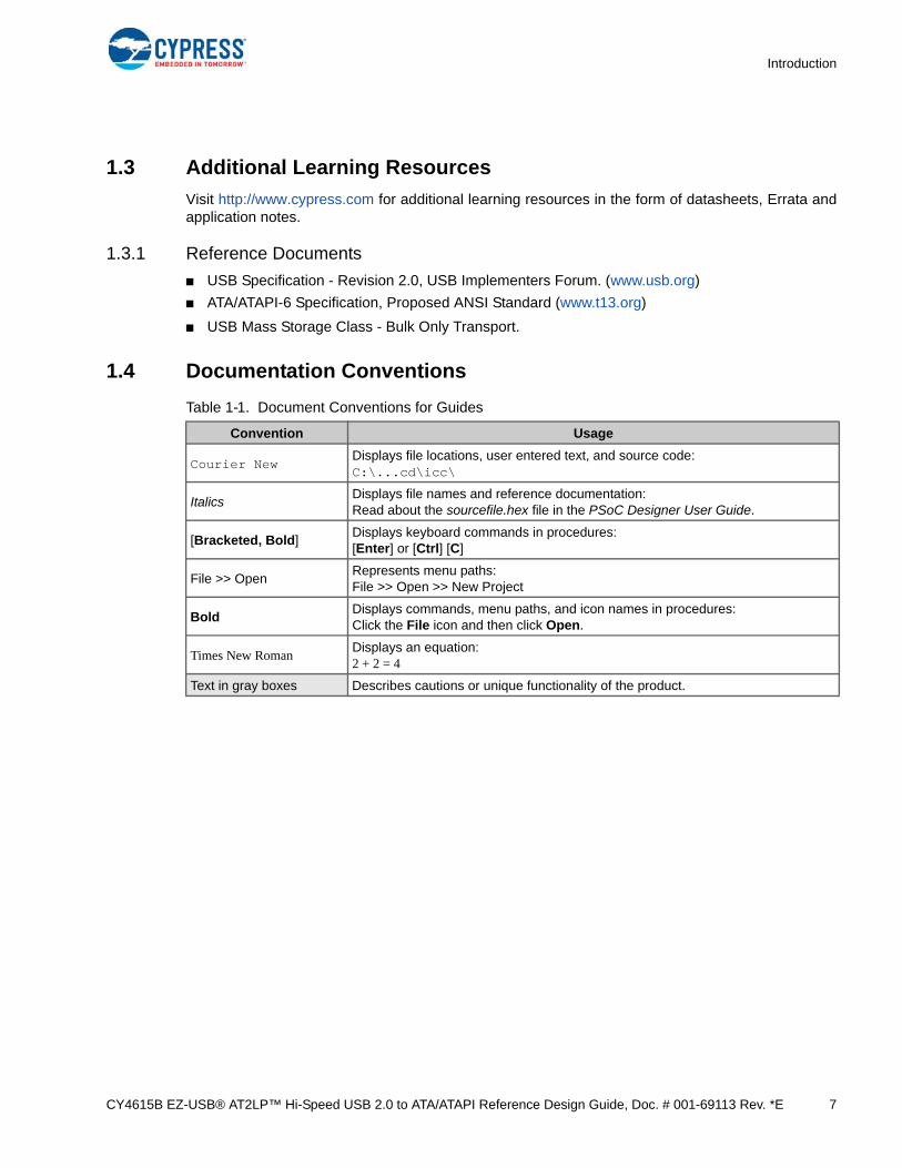
1.4 Documentation Conventions
Table 1-1. Document Conventions for Guides
Convention Usage
Courier NewDisplays file locations, user entered text, and source code:C:\...cd\icc\
ItalicsDisplays file names and reference documentation:Read about the sourcefile.hex file in the PSoC Designer User Guide.
[Bracketed, Bold]Displays keyboard commands in procedures:[Enter] or [Ctrl] [C]
File >> OpenRepresents menu paths:File >> Open >> New Project
BoldDisplays commands, menu paths, and icon names in procedures:Click the File icon and then click Open.
Times New RomanDisplays an equation:2 + 2 = 4
Text in gray boxes Describes cautions or unique functionality of the product.
CY4615B EZ-USB® AT2LP™ Hi-Speed USB 2.0 to ATA/ATAPI Reference Design Guide, Doc. # 001-69113 Rev. *E 8
2. Getting Started
This chapter describes the installation and configuration of the CY4615B AT2LP RDK. It also pro-vides configurations on CY4615B board to connect Compact Flash (CF) card in Bus power modeand ATA devices like DVD /IDE drives in Self-power mode.
2.1 Kit Installation
To install the kit software, follow these steps:
1. Insert the kit CD/DVD into the CD/DVD drive of your PC. The CD/DVD is designed to auto-run and the kit installer startup screen appears. You can also download the latest kit installer ISO file from http://www.cypress.com/go/CY4615B. Create an installer CD/DVD or extract the ISO using WinRar and install the executables.
2. Click “CY4615B AT2LP RDK” to start the installation, as shown in Figure 2-1.
Figure 2-1. Kit Installer Startup Screen
Note: If auto-run does not execute, double-click on the cyautorun.exe file in the root directory of the CD/DVD.
CY4615B EZ-USB® AT2LP™ Hi-Speed USB 2.0 to ATA/ATAPI Reference Design Guide, Doc. # 001-69113 Rev. *E 9
Getting Started
3. The InstallShield Wizard screen appears. The default location for setup is shown on the InstallShield Wizard screen. You can change the location for setup using Change button, as shown in Figure 2-2. Click Next after selecting the installed directory to launch the kit installer
Figure 2-2. InstallShield Wizard
CY4615B EZ-USB® AT2LP™ Hi-Speed USB 2.0 to ATA/ATAPI Reference Design Guide, Doc. # 001-69113 Rev. *E 10
Getting Started
4. On the Product Installation Overview screen, select the installation type that best suits your requirement. The drop-down menu has three options - Typical, Complete, and Custom, as shown in Figure 2-3. For this kit all these types of installations would result in the installation of same set of kit components. Click Next to start the installation
Figure 2-3. Installation Type Options
CY4615B EZ-USB® AT2LP™ Hi-Speed USB 2.0 to ATA/ATAPI Reference Design Guide, Doc. # 001-69113 Rev. *E 11
Getting Started
5. When the installation begins, all packages are listed on the Installation page. A green check mark appears adjacent to every package that is downloaded and installed, as shown in Figure 2-4.
Figure 2-4. Installation Page
CY4615B EZ-USB® AT2LP™ Hi-Speed USB 2.0 to ATA/ATAPI Reference Design Guide, Doc. # 001-69113 Rev. *E 12
Getting Started
6. Wait until all the packages are cached and installed successfully. Click Finish to complete the installation.
Figure 2-5. Installation Completion Page
Note: After software installation, verify your installation and setup.
2.2 Reference Design Kit Contents
After installation of CY4615B contents successfully as explained in Kit Installation on page 8 the kitcontents can be located at install directory <Installed_Directory>\<version>\.The<Installed_Directory> term referenced throughout this document refers toC:\Cypress\USB\CY4615B AT2LP RDK as default path. If the installed directory was modified duringinstallation the corresponding path needs to be verified. Following is the summary of CY4615B kitcontent folders with respect to <Installed_directory>\<version>
■ Documentation-Contains Release notes, Quick start Guide, Kit User Guide (This doc), Applica-tion notes, AT2LP datasheet, Errata...etc related to the kit.
■ Hardware-contains Kit BOM, Schematic, PCB, Gerber and Layout files related to CY4615B board.
■ Manufacturing Software-contains Blaster and Primer tools to program configuration files (.iic) to external I2C EEPROM connected to the AT2LP IC. Using the configuration file parameters CY4615B communicates with different ATA/ATAPI-6 compliant devices.
■ Manufacturing Software\Drivers-This folder contains cypress cyusb4615brdk.inf and cyusb.sys USB driver to bind CY4615B board with PC Host containing Windows OS.The Cypress USB driv-ers are supported on Windows 2000,XP,Vista and 7 on both 32/64-bit processor types.
■ Windows Driver-This folder contains Cypress USB Mass Storage Driver which provides support for the entire line of Cypress USB Mass Storage products (AT2, FX, FX2, ISD-200, ISD-300, ISD-300LP, and SL11R-IDE) on Windows 98 Second Edition, Millennium Edition, 2000 Professional Edition, and XP Home and Professional Editions.
CY4615B EZ-USB® AT2LP™ Hi-Speed USB 2.0 to ATA/ATAPI Reference Design Guide, Doc. # 001-69113 Rev. *E 13
Getting Started
2.3 Quick Start
The AT2LP DVK board is by default configured to connect to a Compact Flash (CF) card in a Bus-powered mode. Please verify the Jumper settings for “Bus-powered CF” mentioned in Recom-mended Settings on page 14. To verify Self-powered ATA devices like DVD and HDD refer toDetecting Self-powered Hard Disk (IDE) Using CY4615B Board on page 16.
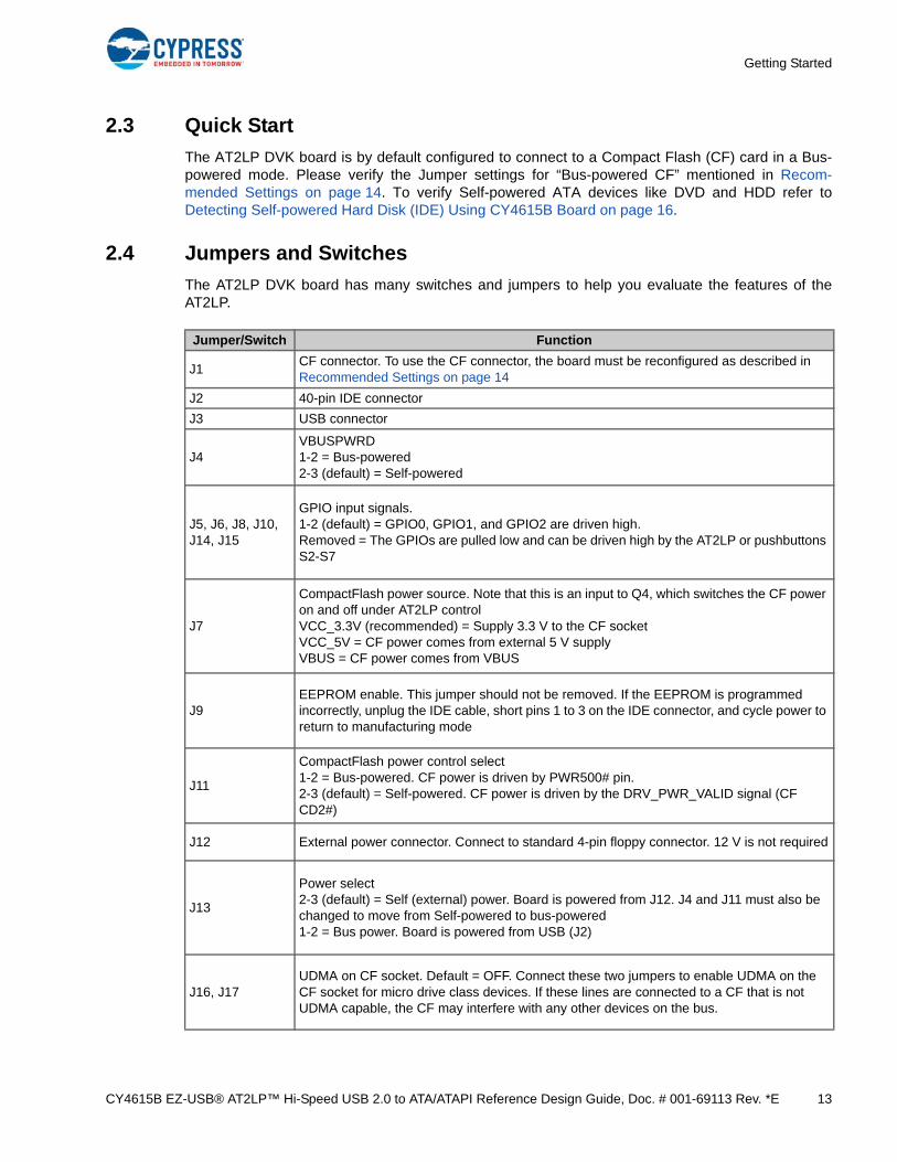
2.4 Jumpers and Switches
The AT2LP DVK board has many switches and jumpers to help you evaluate the features of theAT2LP.
Jumper/Switch Function
J1CF connector. To use the CF connector, the board must be reconfigured as described in Recommended Settings on page 14
GPIO input signals.1-2 (default) = GPIO0, GPIO1, and GPIO2 are driven high.Removed = The GPIOs are pulled low and can be driven high by the AT2LP or pushbuttons S2-S7
J7
CompactFlash power source. Note that this is an input to Q4, which switches the CF power on and off under AT2LP controlVCC_3.3V (recommended) = Supply 3.3 V to the CF socketVCC_5V = CF power comes from external 5 V supplyVBUS = CF power comes from VBUS
J9EEPROM enable. This jumper should not be removed. If the EEPROM is programmed incorrectly, unplug the IDE cable, short pins 1 to 3 on the IDE connector, and cycle power to return to manufacturing mode
J11
CompactFlash power control select1-2 = Bus-powered. CF power is driven by PWR500# pin.2-3 (default) = Self-powered. CF power is driven by the DRV_PWR_VALID signal (CF CD2#)
J12 External power connector. Connect to standard 4-pin floppy connector. 12 V is not required
J13
Power select2-3 (default) = Self (external) power. Board is powered from J12. J4 and J11 must also be changed to move from Self-powered to bus-powered1-2 = Bus power. Board is powered from USB (J2)
J16, J17UDMA on CF socket. Default = OFF. Connect these two jumpers to enable UDMA on the CF socket for micro drive class devices. If these lines are connected to a CF that is not UDMA capable, the CF may interfere with any other devices on the bus.
CY4615B EZ-USB® AT2LP™ Hi-Speed USB 2.0 to ATA/ATAPI Reference Design Guide, Doc. # 001-69113 Rev. *E 14
Getting Started
2.5 DIP Switches
2.6 Pushbutton Switches
2.7 Recommended Settings
Switch Function
SW1-1
ATA_ENOFF (default) = Normal operationON = Disconnect from USB. Tri-state the ATA bus if the EEPROM configuration is set to tri-state.
SW1-2DRV_PWR_VALIDOFF (default) = Normal operationON = Simulate CompactFlash connection
SW1-3 SPARE
SW1-4LED enableOFF = Disable power LED, GPIO LEDsON (default) = Enable power LED, GPIO LEDs
Button Function
S1SYSIRQ: Pushing this button pulls up the SYSIRQ line. This line latches the GPIO pins into the interrupt endpoint. Note that this button has no function when the GPIOs are used in HID mode.
S2-S7When the GPIO pins are used as inputs, they are pulled down by default. These buttons pull the GPIOs high when they are pressed. To tie the GPIOs high for longer periods of time, use J5, J6, J8, J10, J14, and J15.
Jumper/Switch Name Bus-Powered CF Self-Powered DVD or HDD
J1 CF connector CF unused
J2 40-pin IDE connector Unused 80-pin IDE cable
J3 USB connector USB USB
J4 VBUSPWRD 1-2 Bus-powered 2-3 Self-powered
J5, J6, J8, J10, J14, J15
GPIO input signals Application specific Application-specific
J7Compact Flash power source
VCC_3.3V (recommended) = Supply 3.3 V to the CF socket
N/A
J9 EEPROM enable Inserted Inserted
J11Compact Flash power con-trol select
1-2 = Bus-powered. CF power is driven by PWR500# pin.
2-3 = Self-powered. CF power is driven by the DRV_PWR_VALID signal (CF CD2#)
CY4615B EZ-USB® AT2LP™ Hi-Speed USB 2.0 to ATA/ATAPI Reference Design Guide, Doc. # 001-69113 Rev. *E 15
Getting Started
J12 External power connectionDo not supply power through this connector in bus-pow-ered mode.
Connect to standard 4-pin floppy connector. 12V is not required
J13 Power Select1-2 = Bus power. Board is powered from USB (J3).
2-3 (default) = Self (External) power. Board is powered from J12
J16, J17 UDMA on CF socket
Connect these two jumpers to enable UDMA on the CF socket for micro drive class devices. If these lines are connected to a CF that is not UDMA capable, the CF may interfere with any other devices on the bus.
N/A
(CF socket is not used)
SW1-1BUS_PWR_VALID / ATA_EN
Off (ATA is enabled) Off (ATA is enabled)
SW1-2 SPARE
SW1-3 SPARE
SW1-4 LED enableOff = Disable power LED, GPIO LEDs
On (Default) = Enable power LED, GPIO LEDs
CY4615B EZ-USB® AT2LP™ Hi-Speed USB 2.0 to ATA/ATAPI Reference Design Guide, Doc. # 001-69113 Rev. *E 16
Getting Started
2.8 Detecting Self-powered Hard Disk (IDE) Using CY4615B Board
The procedure to detect self powered Hard disk involves the following steps:
1. Binding Cypress Manufacturing Mode USB driver as explained in Binding Cypress Manufacturing Mode USB Driver to Blaster Tool on page 21.This step can be skipped if the binding process was already completed. The Manufacturing Mode USB drivers support Windows XP, Vista, and 7 platforms in both 32 and 64-bit configurations.
2. Program Configuration file (100_self_ATA.iic) to external I2C EEPROM on CY4615B board using Blaster utility. The procedure to program Configuration file is explained in further in section User Interface on page 20 and Using Configuration Files with CY4615B Board on page 22.
3. After programming the configuration file disconnect the USB cable between PC and CY4615B board.
4. Verify the Jumper settings mentioned for Self powered ATA devices in recommended settings in Recommended Settings on page 14.
5. If you are using more than one device, configure one as a master and the other as slave. If you are only using one device, master/slave configuration does not matter.
6. Plug the device into the 40-pin ATA connector via the 80-pin ribbon cable.
7. Connect the 4-pin EXT power (J12) connector to your external power supply.
8. Connect your ATA device to an external power supply.
9. Turn on the power supply and plug the USB cable into a host
10. The Hardware Connections are explained in detailed under “Hardware Connection” section of the Application note titled- Multiple IDE Drives Access using AT2LP - AN63019.The application note explains the hardware set up and PC software configuration process required to access more than one hard drive using AT2LP. It uses AT2LP DVK board (CY4615B) and an 80 conduc-tor IDE cable to interface two self-powered hard drives to the AT2LP. With this set up, when the AT2LP board is connected to the PC using a USB cable, you can access all the logical partitions available in both the drives simultaneously.
2.9 ATA Security
ATA security is supported via ATACB commands, the same method used by the ISD-300LP. ATACBcommands are not supported by the major operating system drivers so the Cypress driver must beused to support ATA security. BIOS authors can find the entire ATACB description in the data sheet.
IDE hard drives only prompt for the password on a hard reset. If the SKIP_PIN_RESET bit is set inthe EEPROM, the device will ask for a password only on initial power-up. If the SKIP_PIN_RESETbit is cleared, the device will ask for a password when it is unplugged from the host or when the hostis power-cycled.
CY4615B EZ-USB® AT2LP™ Hi-Speed USB 2.0 to ATA/ATAPI Reference Design Guide, Doc. # 001-69113 Rev. *E 17
3. Convert AT2 EEPROM to AT2LP
To further aid the transition from the AT2 to the AT2LP, Cypress has developed a simple tool that willconvert the EEPROM configuration files used with the AT2 into a format that can be used with theAT2LP manufacturing software. The AT2 configuration files are text files with a “W56” extension. TheAT2LP configuration files are hex files with an “IIC” extension. The CfgToI2C application reads theW56 files and converts them into IIC format. This tool is located at <Installed_Directory>/<version>/Manufacturing Software/AT2 to AT2LP conversion tool
3.1 User Interface
The application's user interface is simple and intuitive. The top field displays the W56 file that will beconverted to IIC format. The bottom field displays the location into which the newly converted IIC filewill be placed. Click the Convert button to launch the conversion process. Enter the source and des-tination paths manually or use the Browse button to open a browser window to choose the path.
The CfgToI2C application can read several different file types, so make certain that the W56 type isselected in the drop-down menu in the browser window.
Figure 3-1. Configuration File Converter
When the W56 configuration file is converted to the IIC format, it can be used with the AT2LP manu-facturing software. However, the converted file will still follow the format specified in the AT2 datasheet, rather than what is listed in the AT2LP data sheet.
CY4615B EZ-USB® AT2LP™ Hi-Speed USB 2.0 to ATA/ATAPI Reference Design Guide, Doc. # 001-69113 Rev. *E 18
Convert AT2 EEPROM to AT2LP
3.2 EEPROM Settings
Many major functions of the AT2LP are controlled by EEPROM settings. To modify the EEPROMsettings, run the Blaster.exe program located at <Installed_Directory>/<version>/Manufacturing Soft-ware.
If an EEPROM configuration prevents the AT2LP board from enumerating, follow this procedure toget the board into manufacturing mode:
1. Turn off the power
2. Unplug the ATA cable or 80-pin connector and any CompactFlash that is installed
3. Short pins 1 to 3 of the ATA connector with a jumper block
4. Turn on the power
5. The board is now in manufacturing mode. It can be reprogrammed using AT2LPBlaster
Figure 3-2. AT2LP Board
CY4615B EZ-USB® AT2LP™ Hi-Speed USB 2.0 to ATA/ATAPI Reference Design Guide, Doc. # 001-69113 Rev. *E 19
The Cypress AT2LP Configuration Utility Blaster.exe is a PC application software provided with theCY4615B AT2LP DVK. This software is located in the Manufacturing Software folder in the kit instal-lation directory. The AT2LP board is a fixed function device and initially requires EEPROM configura-tion (.iic) files with appropriate configuration information. Blaster.exe software performs the followingmajor operations:
■ Reads the configuration files already pre-programmed to on-board EEPROM
■ Writes the configuration file to on-board EEPROM
The Read configuration files can be modified based on certain ATA-ATAPI parameters to suit a cer-tain type of mass storage device.
4.1.1 Components
The software consists of the executable utility (Blaster.exe), manufacturing driver (CYUSB.sys andcyusb4615brdk.inf), and user guide (this file).
4.1.2 Supported Platforms
The cypress AT2LP Configuration utility has been tested and supports Windows 2000 professional ,Windows XP(32/64 bit),Vista(32/64 bit) and Windows-7(32/64 bit).The utility will not work with Win-dows 95 or any version of Windows NT
4.2 Overview
The Cypress AT2LP uses 16 bytes of configuration settings, which define how the part interacts withthe attached storage device and the USB host. The AT2LP also uses a standard set of USB descrip-tors to provide information about the product to the USB host. The AT2LP contains default configura-tion settings and USB descriptors in its internal ROM. These settings and USB descriptors are notsuitable for use in shipping products, because the USB descriptors do not provide unique serialnumbers, and are therefore not Mass Storage Class compliant. Therefore, circuit designs using theCypress AT2LP store the configuration settings and USB descriptors externally, on either a serialEEPROM, or the attached storage device.
The Cypress AT2LP Configuration Utility is used to edit the configuration settings and USB descrip-tors for the AT2LP. The configuration settings and USB descriptors can be stored in an AT2LP config(.iic) file on the PC, or the utility can work directly with settings and descriptors from a USB-attachedAT2LP-based board.
The Cypress AT2LP Configuration Utility provides developers an opportunity to develop an optimalset of AT2LP configuration settings and USB descriptors by experimenting with those settings anddescriptors on their product. When an optimal configuration is developed, it can be saved to anAT2LP config (.iic) file, which can be used with the Cypress AT2LP Manufacturing Utility for massproduction.
CY4615B EZ-USB® AT2LP™ Hi-Speed USB 2.0 to ATA/ATAPI Reference Design Guide, Doc. # 001-69113 Rev. *E 20
Configuration Utility
4.3 User Interface
The Cypress AT2LP Configuration Utility user interface consists of a single window, as shown in thefollowing image. Blaster.exe is available at <Installed_directory>\<version>\Manufacturing Software.
Figure 4-1. Configuration Utility
Configuration settings can be stored in a file on the PC. The "Read From File…" button at the bot-tom-left of the window opens a file browser and enable you to select a AT2LP config (.iic) file to loadfrom the location <Installed_Directory>\<version>\Manufacturing Software\Config_files. The "WriteTo File…" button at the bottom-right of the window opens a file browser and allows to save theAT2LP config (.iic) file.
Alternatively, the utility can work with configuration settings directly from a USB-attached AT2LPpart. The "Read from Device" controls in the bottom-center of the window enable you to select asource to read the configuration settings from and upload the settings. The sources the configurationsettings can be read from are the serial EEPROM or the internal RAM.
The configuration settings can also be downloaded directly to the USB attached AT2LP part. The"Write to Device" controls at the bottom-right of the window enable you to select the destination towrite to and download the settings. The configuration settings can be written to the serial EEPROMor the internal RAM.
Note: The AT2LP's internal RAM only contains device configuration settings and not the USBdescriptors.
CY4615B EZ-USB® AT2LP™ Hi-Speed USB 2.0 to ATA/ATAPI Reference Design Guide, Doc. # 001-69113 Rev. *E 21
Configuration Utility
The tabs at the top-left of the window provides a parsed display of the configuration settings andUSB descriptors. All configuration settings and USB descriptors are displayed on one of the six tabs(Device Settings, General Device Desc., Configuration Desc., Mass Storage Interface, HID Inter-face, and CSM Interface). Not all configuration settings or USB descriptor fields can be edited inparsed display. If a field cannot be edited, it is because it is a read-only, obsolete, or utility-managedvalue. The definitions of the configuration settings fields on the Device Settings tab is available in theCypress AT2LP data sheet “Table 11. Configuration Data Organization”. The definitions of the USBdescriptor fields on the General Device Desc., Configuration Desc., High-Speed Interface Desc, andFull-Speed Interface Desc. tabs can be found in the same table and also in the Chapter-9 of the USB2.0 Specification.
The table to the right of the window named Raw Configuration Data displays the configuration set-tings and USB descriptors in a raw format (as they are stored). The contents of this table can beedited and provide a way for advanced developers to edit settings that cannot be edited in theparsed display.
4.4 Binding Cypress Manufacturing Mode USB Driver to Blaster Tool
The Blaster Configuration Utility in windows PC requires Cypress Manufacturing Mode USB driver toupload or download configuration file(.iic) to external I2C EEPROM connected to AT2LP. The driverconsists of two parts, the device driver (cyusb.sys), and the driver information file(cyusb4615brdk.inf). Both files are located in the Drivers sub-directory, which can be found in thesame directory as the Blaster.exe application file located at (<Installed_Directory>\<version>\Manu-facturing Software\).
4.4.1 Installing Cypress Manufacturing Mode USB Driver
The CY4615B board by default is programmed to connect with Compact Flash (CF) card in Buspower mode. As a result, it is necessary for the user to change jumper settings specify to detectCypress Manufacturing driver. Follow these steps to install the Cypress Manufacturing mode driverfor the CY4615B board:
1. Disconnect USB A-to-B cable between USB connector (J9) on CY4615B board and PC.
2. Short pins 1-3 of the 40-pin ATA connector J2. This is to ensure the AT2LP boots in Manufactur-ing Mode with VID/PID-0x04B4/6830. Ensure J9 is open to ensure CY4615B does not boot with default configuration File(.iic) in external EEPROM.
3. Connect USB A-to-B cable between PC USB Host controller port and Type-B connector (J3) on CY4615B board and PC.
4. The Hardware Update wizard window pops up due to enumeration of CY4615B enumeration in manufacturing mode. Select the Yes, this time only option and click Next. In Windows Vista/7 machine choose “Browse My computer for driver software”
5. In the next window, select Install from a list or specific location and click Next.
6. Select Dont search. I will choose driver to install and click Next.
7. Select “Universal Serial Bus Controllers” in the next Window.Click on the Have Disk button in the next window. A new window pops up on top of the existing window.
8. In Windows Vista/7 machines browse directly after step-4 to matching Driver information file as mentioned below. Click Browse and point to the driver path for each OS and select the INF file as shown in the below path
a. Windows XP 32-bit: <Installed_Directory>\<version>\Manufacturing Software\Drivers\wxp\x86
b. Windows XP 64-bit: <Installed_Directory>\<version>\Manufacturing Software\Drivers\wxp\x64
c. Windows Vista/7 32-bit:<Installed_Directory>\<version>\Manufacturing Software\Driv-ers\wlh\x86
CY4615B EZ-USB® AT2LP™ Hi-Speed USB 2.0 to ATA/ATAPI Reference Design Guide, Doc. # 001-69113 Rev. *E 22
Configuration Utility
d. Windows Vista/7 64-bit: <Installed_Directory>\<version>\Manufacturing Software\Driv-ers\wlh\x64
9. For Windows XP 32-/64-bit, Vista, and Windows 7 in 32-bit configurations, it is not required for the drivers to be digitally signed. The cyusb.sys supplied with the kit is an unsigned driver and Windows may present a warning dialog. Choose Continue on the warning dialog. For more infor-mation on signing drivers, look at Windows Hardware Quality Labs (WHQL) documentation on the Microsoft website.
10.For Windows Vista and Windows 7 64-bit machines, we need to turn off the Driver Signature Enforcement by rebooting the PC OS with Advanced Boot Options (accessed via F8 on boot up). Click on Disable Driver Signature Enforcement; repeat steps 2 and 3. The Cypress driver cyusb.sys is not digitally signed and can be properly installed only when the Driver Signature Enforcement is turned off. This setting is temporary and does not propagate to the next reboot automatically.
11.Because the drivers are not digitally signed, Windows cannot verify the publisher and throws security warning. Choose Install this driver software anyway option to begin installation.
12.The hardware wizard now reports successful installation of the Cypress driver for the CY4615B board. Open the device manager by right clicking on My computer/Computer properties, select Hardware Tab and click on Device Manager Button. Observe the updated CY4615B board name (as defined in the cyusb4615brdk.inf file) in the expanded list of USB controllers.
13.However, if you reprogram devices that have already been programmed with a different Vendor ID and Product ID combination, the driver information file needs to be modified so that the driver matches the new VID/PID. The driver information file can be edited in any plain text editor (such as Notepad) to add support for a new VID/PID. Comments are included in the driver information file indicating where to add new entries to enable support for a new VID/PID. For more details about modifying the driver information file, see application note, AN61465, which is part of the kit documentation
Note: The Cypress USB Driver package (cyusb4615brdk.inf and cyusb.sys) are unsigned driverpackage i.e they do not contain Microsoft digital signature.The driver package must be used only forprogramming Configuration files (.iic) files and validate the functionality of different ATA/ATAPIdevices using AT2LP board. Microsoft provides native drivers to support(usbstor.sys)Mass storagefunctionality. Both Manufacturing and Mass storage modes of AT2LP board use common VID/PID-0x04B4/0x6830.To avoid driver loading problems between windows native mass storage driver andCypress Manufacturing mode drivers(if digitally signed) the current USB driver package is notWHQL certified. Please use step-10 as workaround to load cypress USB driver package in WindowsVista/7 64-bit OS.The unsigned driver loading problems are not stringent in 32-bit configuration ofWindows OS.
4.5 Using Configuration Files with CY4615B Board
Several configuration files (.iic) of 170-200 bytes size are provided along with the kit to verifyCY4615B kit functionality with various ATA/ATAPI-6 compliant devices like Compact Flash, DVD,CDROM, HDD, and so on. Refer to ReadMe.txt (under Installed_Directory>\<version>\Manufactur-ing Software\Config_files) to understand the complete functionality of each file. After binding theCY4615B board to the Cypress Manufacturing Mode USB Driver Short Jumper-J9 to connect exter-nal I2C EEPROM to AT2LP.The user can now Read/Write Configuration file parameters to externalI2C EEPROM as explained User Interface on page 20.
This software tool located at “<Installed_Directory>\<version>\Manufacturing Software” allows you toprogram the EEPROM configuration (.iic) files at the click of a button. The tool initially prompts you toplug-in the AT2LP device and then the EEPROM is automatically programmed with the image spec-ified as a configuration file. The status box of this software window turns yellow during programming,green if successful, or red if otherwise. This tool does not allow you to change any of the ATA/ATAPIparameters such as the Blaster tool. The tool is useful for mass programming of AT2LP boards.
5.1.1 Components
The software consists of the executable utility (Primer.exe), a configuration file (Primer.ini), manufac-turing driver (cyusb.sys and cyusb4615brdk.inf), and user guide (this file).
5.1.2 Supported Platforms
The Cypress AT2LP Manufacturing Utility has been tested and is supported on Windows 2000 pro-fessional, Windows XP(32/64 bit), Vista(32/64 bit), and Windows-7(32/64 bit). The utility is not sup-ported on Windows Millennium Edition or Windows 98. The utility will not work with Windows 95 orany version of Windows NT.
5.2 Overview
Circuit designs using the Cypress AT2LP use a serial EEPROM to store the device firmware. ForAT2LP-based designs, the EEPROM can conveniently be programmed via the USB interface usingthe Cypress AT2LP Manufacturing Utility. The Cypress AT2LP Manufacturing Utility software isinvoked by double-clicking the Primer.exe icon. The Cypress AT2LP Manufacturing Utility has a verysimple user interface consisting of a single screen that guides the user through the programmingprocess. Manufacturing options for the Cypress AT2LP Manufacturing Utility can be adjusted using aconfiguration file (Primer.ini).
CY4615B EZ-USB® AT2LP™ Hi-Speed USB 2.0 to ATA/ATAPI Reference Design Guide, Doc. # 001-69113 Rev. *E 24
AT2LP Manufacturing Software
5.3 User Interface
Figure 5-1 shows the user interface for the Cypress AT2LP Manufacturing Utility. The name of thefirmware image file used to program devices is shown in the box at the bottom-left of the window.The programming process can be abandoned at any point by closing the window, which will quit theapplication. The Instruction field displays instructions to the user. The Status field indicates the pro-gramming process.
First, plug in the device to be programmed. Note that due to a limitation in Windows, if the device isalready plugged in when the utility is started, the utility will not be able to detect it.
Figure 5-1. Manufacturing Utility
When the device is plugged in, the external EEPROM is programmed using the firmware imagespecified in the configuration file. During this step, the background of the Status field turns yellow,and the text indicates that the device is being programmed.
If the device is successfully programmed, the Status field turns green, and the status message "Pro-gramming Succeeded" is displayed. If the device cannot be programmed successfully, the Statusfield turns red, and the status message "Programming Failed" is displayed. The user is prompted todisconnect the device and plug in the next device.
CY4615B EZ-USB® AT2LP™ Hi-Speed USB 2.0 to ATA/ATAPI Reference Design Guide, Doc. # 001-69113 Rev. *E 25
AT2LP Manufacturing Software
5.4 Configuration File
The Cypress AT2LP Manufacturing Utility uses a configuration file (Primer.ini) to configure the globalsettings in the utility. This file can be found in the same directory as the Primer.exe application file.The file can be edited in any plain text editor (such as Notepad) to change the global settings.
When the file is opened in a text editor, the following is displayed:
//
// Manufacturing SW Custom Settings
//
// Copyright (c) 2012 Cypress Semiconductor
//
[General]
[DefStartupOpts]
SerNumPrefix=0xDEF1 ;SN prefix value (0xDEF1 is default)
ConfigFile=CFGFiles\100_bus_CF.iic ;The AT2LP config file to load at startup
The SerNumPrefix should contain the four digit serial number prefix. The utility generates serialnumbers based upon the host computer's clock. To guarantee uniqueness, the serial number prefixshould be different for each host computer being used to program devices. The ConfigFile settingtells the utility which firmware image file to download to devices. Note that the ConfigFile settingmust contain the complete path to the firmware image file. If a relative path is used, it is consideredto start from the directory where the utility resides. The "." (current directory) and ".." (parent direc-tory) path designators do not work for the ConfigFile setting.
5.5 Driver
The Cypress AT2LP Manufacturing Utility requires a special device driver to download device firm-ware to the external EEPROM and test AT2LP-based devices. Refer Binding Cypress ManufacturingMode USB Driver to Blaster Tool on page 21 for more details on installing the manufacturing modeUSB driver.
CY4615B EZ-USB® AT2LP™ Hi-Speed USB 2.0 to ATA/ATAPI Reference Design Guide, Doc. # 001-69113 Rev. *E 26
6. Resources
6.1 Hardware Resources
The CY4615B AT2LP DVK software kit has several hardware resources that guide you in designingyour own custom board. Some documents in the hardware directory of the DVK kit software are:
■ CY4615B_PCBA_BOM.xls: This document lists all the vendor hardware components used in designing the AT2LP DVK board.
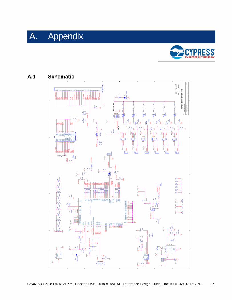
■ CY4615B_Schematic.DSN and CY4615B_Schematic.pdf: These document shows the schematic design of the DVK board.
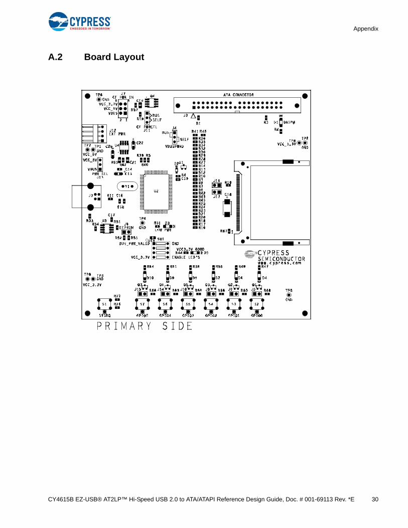
■ CY4615B_Board Layout.brd and CY4615B_Board Layout.pdf: These files can be opened in the PCB software (for example Allegro) to understand the via, trace lengths, and so on of the AT2LP DVK board.
■ CY4615B_Gerber.zip: Contains the gerber files for CY4615B DVK
6.2 Firmware Resources
The CY4615B AT2LP board is designed based on CY7C68320C. This is a fixed function device andrequires only EEPROM configuration files (.iic) in the range of 170 to 200 bytes to communicate withdifferent ATA-ATAPI-6 compliant mass storage devices.
The CY4611B is a reference design based on the FX2LP chip, which is a firmware programmableversion. This firmware contains all the ATA/ATAPI-6 commands support to communicate with differ-ent storage devices. For more information on this kit, see Reference Designs on page 28.
6.3 Application Notes
For the AT2LP family of chipsets, the following documents are available on the Cypress website:
■ Working with INF File of Device using CyUSB.sys - AN61465
Microsoft Windows uses the INF file to bind a device to its appropriate driver. If a window has a native driver for that USB device class, then an INF file is not required and the device is bound to the native driver. However, to bind the device to a custom driver, a custom INF file is required. This application note describes the sections of the INF file and provides guidelines to modify them based on requirement.
■ EZ-USB AT2LP™ Features - AN5071
This application note describes the features in the AT2LP that are new to the AT2 family of chips, as well as any features that may behave differently than with the previous AT2 chips.
■ Migrating from CY7C68300A (AT2) to CY7C68300B/C (AT2LP) - AN5047C
This application note discusses the hardware and some of the EEPROM configuration changes to be done when end customer designs switch from older AT2 chipsets to newer AT2LP. The AT2LP is an enhanced version of older AT2 series. Only a few schematic changes need to be done because both series of chipsets are pin-to-pin compatible.
This application note provides a detailed review of important hardware circuits such as RESET, crystal, EEPROM, and power on AT2LP DVK board (CY4615B). The document serves as a guideline to avoid problems when designing a custom AT2LP board.
■ Troubleshooting USB 2.0 Signal Quality -AN13632
This application note outlines the problems in measuring signal quality of the USB. It helps the designer to isolate setup issues from design issues.
■ High-speed USB PCB Layout Recommendations - AN1168
This application note describes general guidelines to be followed when designing any Cypress high-speed USB 2.0 device products based on the FX2LP/NX2LP/AT2LP family of chips.
■ Multiple IDE Drives Access using AT2LP - AN63019
This application note explains the hardware set up and PC software configuration process required to access more than one hard drive using AT2LP. It uses AT2LP DVK board (CY4615B) and a 80 conductor IDE cable to interface two self-powered hard drives to the AT2LP. With this set up, when the AT2LP board is connected to the PC using a USB cable, you can access all the logical partitions available in both the drives simultaneously.
■ AT2LP Revision: C Reset Issue and Workaround - AN14569
This application note describes the hard drive hang-up failure seen during boot time (or) soft reset in AT2LP Rev. C chipsets. The note suggests a workaround on how to modify the RESET duration of AT2LP using the Blaster tool software.
CY4615B EZ-USB® AT2LP™ Hi-Speed USB 2.0 to ATA/ATAPI Reference Design Guide, Doc. # 001-69113 Rev. *E 28
7. Reference Designs
7.1 CY4611B - USB 2.0 to ATA Reference Design
You can test a variety of storage devices using the CY4615 DVK board by changing only theEEPROM configuration (.iic) files, but storage device related features cannot be updated. TheCY4611B reference design kit can be used to add or update features. The board that comes alongwith CY4611B is based on the EZ-USB FX2LP™ chip, a general-purpose USB 2.0 high-speeddevice. After programming the ATA/ATAPI command processing firmware and the configuration files(.iic) combined, the board emulates AT2LP (similar to CY4615B DVK board). Here, you can modifythe firmware by adding new features or modifying the existing firmware logic. The reference designkit contains documents related to hardware, firmware, and application software useful while workingwith the board available in this kit.
7.2 CY4651 v1.3 - Cypress and AuthenTec Reference Design for Biometric Security in External USB Hard Disk Drives
The CY4651 is a third-party reference design from AuthenTec. The design uses the AuthenTecEntrePad 2510, biometric fingerprint slide sensor, and Cypress's EZ-USB FX2LP microcontroller, theindustry's most popular high-speed USB 2.0 microcontroller, which interfaces with AuthenTec's sen-sor and delivers data from the HDD to the host computer.
Item Qty Reference Description Manufacturer Mfr Part Number
CY4615B EZ-USB® AT2LP™ Hi-Speed USB 2.0 to ATA/ATAPI Reference Design Guide, Doc. # 001-69113 Rev. *E 34
Appendix
44 5** SEE ADDITIONAL ASSY INST.**
SHUNTS 2 POSITION SULLINS SSC02SYAN
45 1LABEL (DO NOT PLACE NEAR J1)
SERIAL NUMBER XXXXXX
46 1LABEL (DO NOT PLACE NEAR J1)
ASSEMBLY NUMBER PCA: 121-26500 PCA: 121-26500
47 4INSTALL TO THE 4 CORNERS
FEET RUBBER SELF ADHESIVE
3M SJ-5518-BLACK
**Additional Assembly Instructions**1. Place one shunt on each of the following jumpers: J9.2. Place one shunt on pins 1 and 2 of each of the following jumpers: J4,J11,J133. Place one shunt on pins 5 and 6 of each of the following jumpers: J7.4. Place the labels (items 45-46) on the top side of the board.
Item Qty Reference Description Manufacturer Mfr Part Number
CY4615B EZ-USB® AT2LP™ Hi-Speed USB 2.0 to ATA/ATAPI Reference Design Guide, Doc. # 001-69113 Rev. *E 35
Revision History
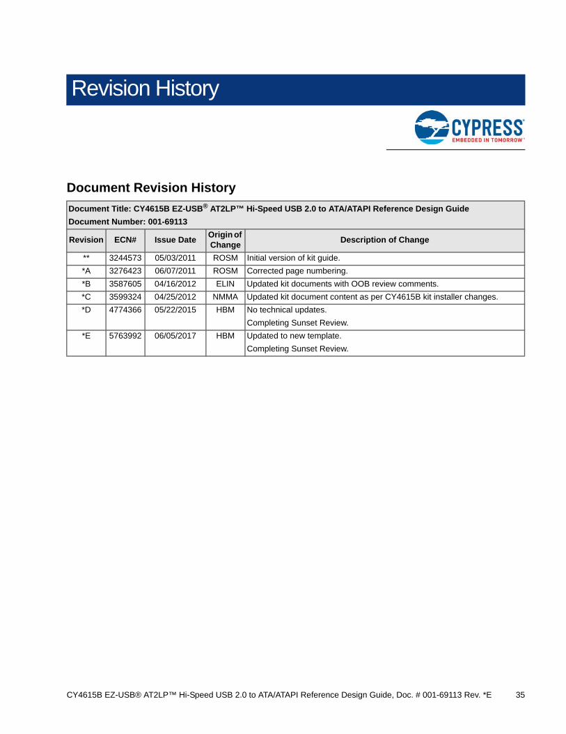
Document Revision History
Document Title: CY4615B EZ-USB® AT2LP™ Hi-Speed USB 2.0 to ATA/ATAPI Reference Design Guide
Document Number: 001-69113
Revision ECN# Issue DateOrigin of Change
Description of Change
** 3244573 05/03/2011 ROSM Initial version of kit guide.