Any Source Code (software and/or firmware) is owned by Cypress Semiconductor Corporation (Cypress) and is protected byand subject to worldwide patent protection (United States and foreign), United States copyright laws and international treatyprovisions. Cypress hereby grants to licensee a personal, non-exclusive, non-transferable license to copy, use, modify, createderivative works of, and compile the Cypress Source Code and derivative works for the sole purpose of creating custom soft-ware and or firmware in support of licensee product to be used only in conjunction with a Cypress integrated circuit as speci-fied in the applicable agreement. Any reproduction, modification, translation, compilation, or representation of this SourceCode except as specified above is prohibited without the express written permission of Cypress.
Disclaimer: CYPRESS MAKES NO WARRANTY OF ANY KIND, EXPRESS OR IMPLIED, WITH REGARD TO THIS MATE-RIAL, INCLUDING, BUT NOT LIMITED TO, THE IMPLIED WARRANTIES OF MERCHANTABILITY AND FITNESS FOR APARTICULAR PURPOSE. Cypress reserves the right to make changes without further notice to the materials describedherein. Cypress does not assume any liability arising out of the application or use of any product or circuit described herein.Cypress does not authorize its products for use as critical components in life-support systems where a malfunction or failuremay reasonably be expected to result in significant injury to the user. The inclusion of Cypress’ product in a life-support sys-tems application implies that the manufacturer assumes all risk of such use and in doing so indemnifies Cypress against allcharges.
Use may be limited by and subject to the applicable Cypress software license agreement.
PSoC Designer™, PSoC Creator™, and Programmable System-on-Chip™ are trademarks and PSoC® is a registered trade-mark of Cypress Semiconductor Corp. All other trademarks or registered trademarks referenced herein are property of therespective corporations.
Flash Code Protection
Cypress products meet the specifications contained in their particular Cypress PSoC Data Sheets. Cypress believes that itsfamily of PSoC products is one of the most secure families of its kind on the market today, regardless of how they are used.There may be methods, unknown to Cypress, that can breach the code protection features. Any of these methods, to ourknowledge, would be dishonest and possibly illegal. Neither Cypress nor any other semiconductor manufacturer can guaran-tee the security of their code. Code protection does not mean that we are guaranteeing the product as "unbreakable."
Cypress is willing to work with the customer who is concerned about the integrity of their code. Code protection is constantlyevolving. We at Cypress are committed to continuously improving the code protection features of our products.
3.1.1 Hardware Jumpers...........................................................................................93.2 Install Software ..........................................................................................................103.3 Verify Kit Version .......................................................................................................11
4. Code Examples 13
4.1 PSoC Rocks ..............................................................................................................134.1.1 Open the PSoC Rocks Project.......................................................................134.1.2 Modify PSoC Rocks Project ...........................................................................134.1.3 Build, Program, and Run the PSoC Rocks Project ........................................144.1.4 Schematic Design PSoC Creator...................................................................154.1.5 How the PSoC Rocks Project Works .............................................................164.1.6 PCB Schematic ..............................................................................................18
4.2 Bubble Level Emulator...............................................................................................194.2.1 How the Bubble Level Emulator Project Works .............................................204.2.2 PCB Schematic ..............................................................................................21
4.3 ThermistorTemperatureSense...................................................................................224.3.1 How the ThermistorTemperatureSense Project Works ..................................22
4.3.1.1 Temperature Sensing Design Principle ...........................................234.3.2 PCB Schematic ..............................................................................................24
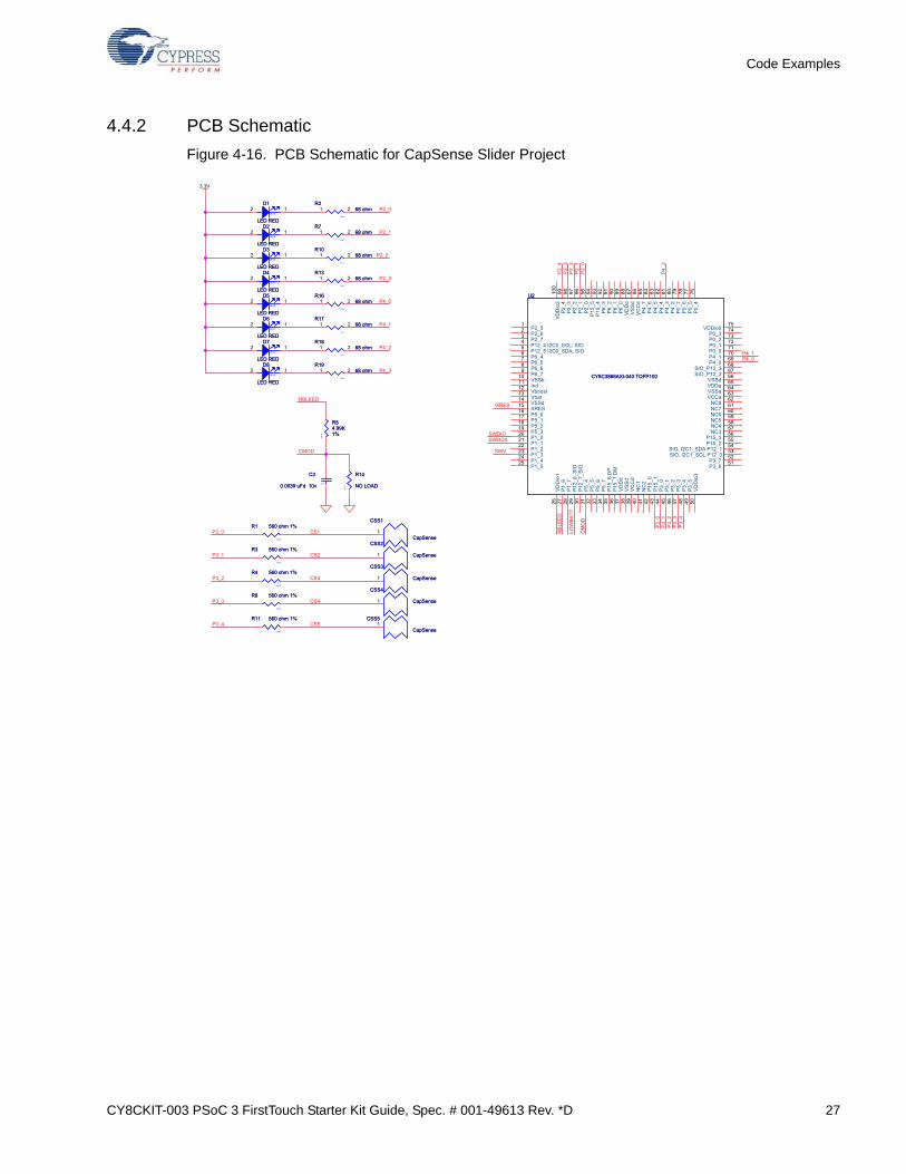
4.4 CapSense Slider........................................................................................................254.4.1 How the CapSense Slider Project Works.......................................................254.4.2 PCB Schematic ..............................................................................................27
4.5 Proximity Sensor........................................................................................................284.5.1 How the Proximity Sensor Project Works ......................................................294.5.2 PCB Schematic ..............................................................................................30
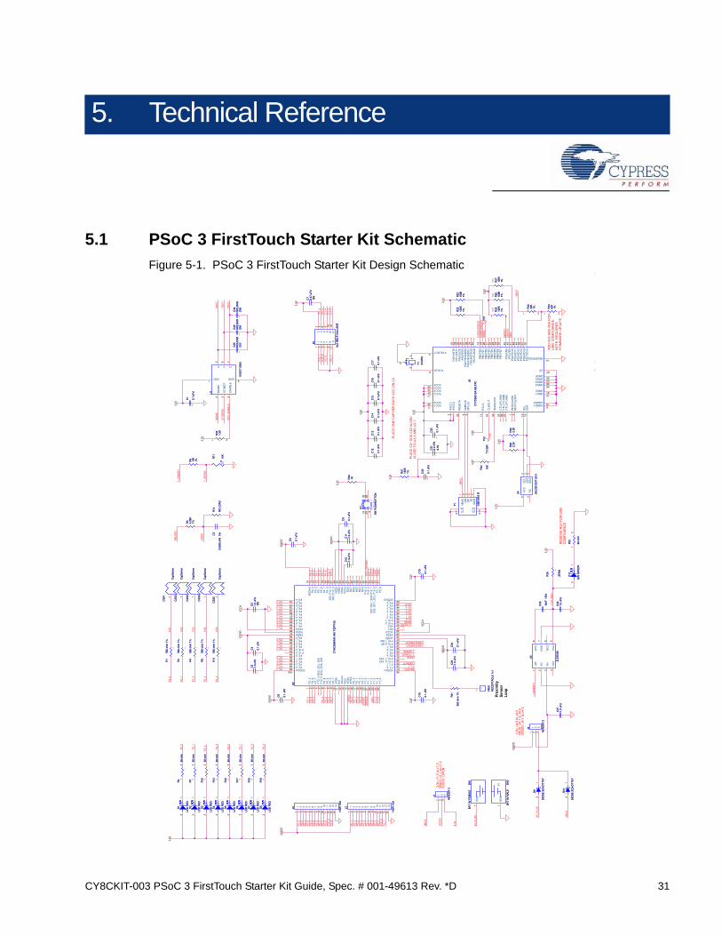
5.1.3 Bill of Material (BOM) ....................................................................................355.2 PSoC 3 Pin Assignment on PSoC 3 FirstTouch Starter Kit Board ............................37
Thank you for purchasing the CY8CKIT-003 PSoC® 3 FirstTouch™ Starter Kit.
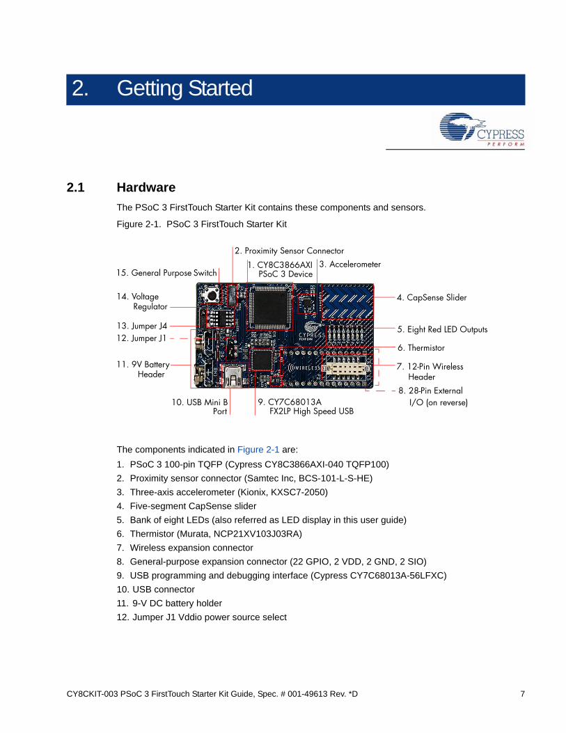
The PSoC 3 FirstTouch Starter Kit is designed to introduce you to the PSoC programmable system-on-chip design methodology and Cypress's new PSoC 3 architecture. This full-featured starter kitships with an array of sensors, I/Os, projects, and software to quickly get you up to speed with PSoCCreator and our powerful design methodology so you can easily evaluate PSoC and see whatvalues the solution can provide.
This kit, in addition to our new PSoC 3 architecture, features the following:
■ PSoC Creator development software with an integrated, free-edition Keil C51 Compiler
■ USB-based serial wire debugging (SWD) protocol programmer and debug interface
■ Accelerometer analog sensor
■ Thermistor analog sensor
■ Proximity analog sensor
■ CapSense® analog touch-sensing interface
■ 28-pin general purpose I/O pins
■ 12-pin wireless module header
This guide provides instructions on how to easily evaluate the PSoC 3 architecture and PSoC Cre-ator design methodology through five code examples.
If you have questions about or need help with this kit, visit our online technical support center athttp://www.cypress.com/go/support for support options, or contact your local Cypress salesrepresentative or authorized distributor.
1.2 Kit Contents
PSoC 3 FirstTouch Starter Kit contains:
■ Evaluation board
■ Quick start guide
■ Kit CD
■ USB A to mini B cable
■ Proximity wire (for use as proximity detection antenna)
The VDDIO1 and VDDIO3 power domains are always powered by 3.3 V. The VDDIO0 and VDDIO2can range from 1.8 V to 5 V depending on the J1 and J4 jumper settings. See Hardware Jumpers onpage 32 for more details.
Note Wireless modules such as ArtaFlex Radio Modules or Cypress Low power Radio modulessuch as CYWM6934/35 (not provided with the kit) can be plugged into the Wireless expansion con-nector on board. You can design your own radio module using the Cypress CyFI-Low power chipCYRF7936-40LXI.
This section shows you how to use the PSoC 3 FirstTouch Starter Kit.
Note This kit comes with a factory programmed demonstration to display "PSoC Rocks!" messageon the LED display when the board is waved.
1. Unpack the PSoC 3 FirstTouch Starter Kit.
2. Connect a 9-V DC battery to the battery connector on the kit board.
3. Hold the board and battery exposing the LEDs. Then, continuously wave the board from side to side in the plane of the PCB (shown in Figure 3-1).
4. As you wave the board, the rasterized image of the message "PSoC Rocks!" appears, as shown in the following figure.
5. Keep waving. The message changes every few seconds.
Figure 3-1. Rasterized Image of "PSoC Rocks!"
3.1.1 Hardware Jumpers
There are two jumpers for power configuration. All examples are run with the default setup of 3.3 Voperation. This requires J1-2 to connect to J1-3 and J4-2 to connect to J4-3. For all other configura-tions, see section 5.1.1 Hardware Jumpers on page 32.
When installing the PSoC 3 FirstTouch Starter Kit, the installer checks if the prerequisites, PSoCCreator, PSoC Programmer, Windows Installer, Windows.NET, Acrobat Reader, and Keil C51Compiler, are installed in your PC. If these applications are not installed, then the installer promptsyou to install them.
1. Insert the kit CD into the your PC. The CD is designed to automatically open an installation dialog (see Figure 3-3). If it does not automatically open, manually open this by running cyautorun.exe on the kit CD.
Figure 3-2. Auto Run File View
2. The kit CD installation dialog prompts you to open this file or begin installing the development environment software. Click the Install PSoC 3 FirstTouch Starter Kit menu item.
Figure 3-3. Installation Dialog.
3. As specified, this installation process first determines if you have all prerequisite software. Follow the on-screen dialogs to complete all required installations. After following these steps, you must have the following software installed:
e. PSoC 3 FirstTouch Starter Kit example projects and documentation
4. Following the software installation, verify you have all hardware and drivers set up for the PSoC 3 FirstTouch Starter Kit by connecting the kit board to your PC via its USB interface. Because this is the first time you have connected this board to this PC, initial driver installations occur. Follow any on-screen dialogs that appear to complete the installation process.
5. Now, verify your installation and setup by opening PSoC Programmer with the kit board attached over USB. Open PSoC Programmer. In the port selection frame, you should see the PSoC 3 FirstTouch starter kit. If you do, you have successfully installed all required software and drivers to begin your PSoC 3 evaluation. Congratulations!
6. Close PSoC Programmer.
7. Open PSoC Creator and continue to the next section to experiment with the included code examples.
3.3 Verify Kit Version
To know the kit revision, look for the white sticker on the bottom left on the reverse of the kit box. Ifthe revision reads CY8CKIT-003A Rev **, then, you own the latest version.
You can also check the silicon marketing part number on the board. If the part number isCY8C3866AXI-040, then you own the latest version and this kit is equipped with production PSoC 3silicon.
To upgrade CY8CKIT-003 to CY8CKIT-003A, you can purchase our latest kits at www.cypress.com/go/CY8CKIT-003.
The PSoC Rocks project displays a rasterized image of the user defined message ("PSoC Rocks!")using persistence of vision. Waving the circuit board back and forth quickly in the plane of the boardgenerates the message.
4.1.1 Open the PSoC Rocks Project
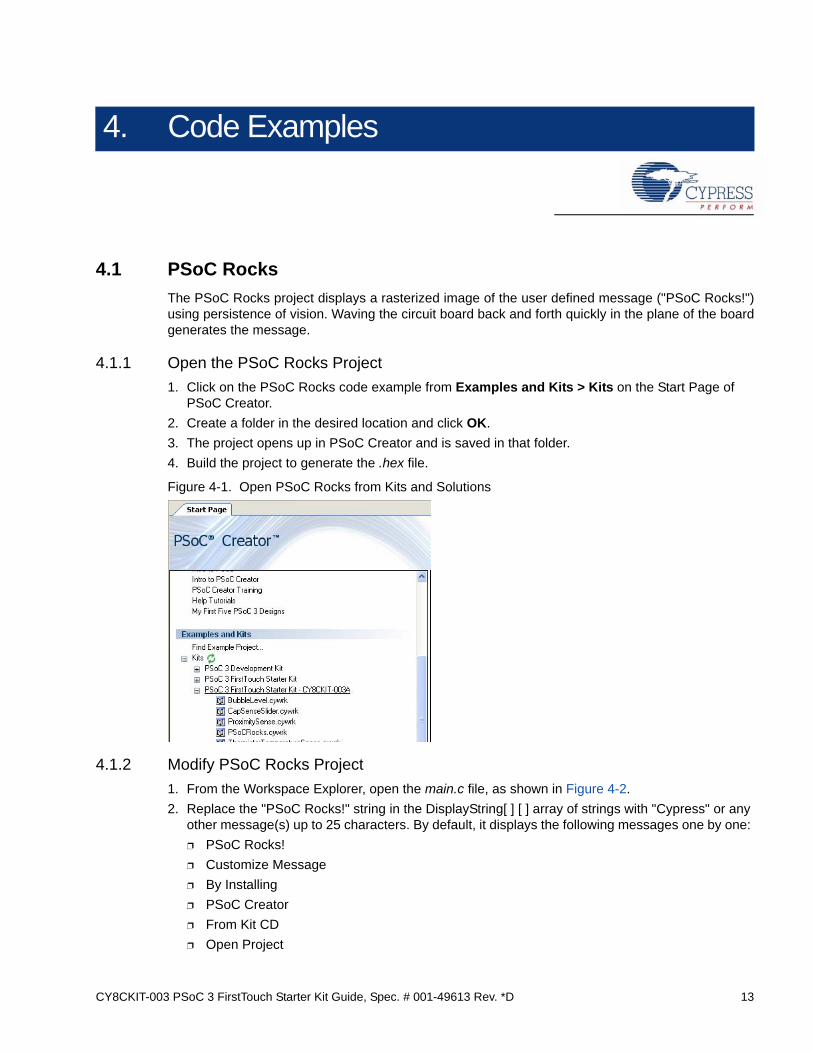
1. Click on the PSoC Rocks code example from Examples and Kits > Kits on the Start Page of PSoC Creator.
2. Create a folder in the desired location and click OK.
3. The project opens up in PSoC Creator and is saved in that folder.
4. Build the project to generate the .hex file.
Figure 4-1. Open PSoC Rocks from Kits and Solutions
4.1.2 Modify PSoC Rocks Project
1. From the Workspace Explorer, open the main.c file, as shown in Figure 4-2.
2. Replace the "PSoC Rocks!" string in the DisplayString[ ] [ ] array of strings with "Cypress" or any other message(s) up to 25 characters. By default, it displays the following messages one by one:
3. The number of times each string in the array is displayed can be adjusted by modifying the respective entry in the StringCycles[ ] array. Valid entries are 1 to 255.
4.1.3 Build, Program, and Run the PSoC Rocks Project
1. Build the project by selecting Build Build PSoCRocks.
Figure 4-3. Build PSoCRocks
2. Connect the PSoC 3 FirstTouch Starter Kit board to your PC by using a USB cable.
3. Click the Program icon.
Figure 4-4. Program
4. The project is programmed successfully, as shown in Figure 4-5.
5. When the download is complete, remove the USB cable from the PSoC 3 FirstTouch Starter Kit board and connect a 9-V battery to the battery connector.
6. Follow the steps in section 3.1 Install Hardware on page 9 to see your message displayed.
4.1.4 Schematic Design PSoC Creator
To view this project's customized hardware configuration, open the TopDesign.cysch file located inthe Workspace Explorer window. PSoC Creator's schematic design entry methodology, using pre-defined peripheral functions called components, allows rapid hardware definition andimplementation.
The schematic entry system works similar to standard circuit board schematic entry tools, with theexception that all components and routing are automatically implemented within the PSoC devicerather than on a PCB. This allows you to create custom solutions using peripherals commonly foundin MCU designs as well as analog peripherals, digital peripherals, and logic, not possible with anyother microcontroller or system-on-chip. In many designs, traditionally external resources can befully integrated within the PSoC device.
The PSoC Rocks design schematic uses several peripheral and circuit elements. A single analoginput pin connected to the accelerometer's Y axis is routed to an ADC. A pin component with threepins is used to control the functionality of the accelerometer and another pair is used to drive theLEDs. The last schematic element is a control register that is used to drive the LED pins. The controlregister output is inverted to sink current from the LEDs. This allows the LEDs to be driven externallywith the highest possible current and brightness without adding complexity to the design.Conventional systems require firmware overhead to decode and invert the data for each of theaffected LED pins.
The PSoC Rocks schematic (see Figure 4-6 on page 16) provides a small sample of how customhardware and peripherals are possible in PSoC devices. Each component selected from thecomponent catalog and placed on to the project schematic provides a GUI, configurable parameters,and data sheet to further customize its operation in the design. During the project build process,each component generates the required hardware configuration and firmware APIs as necessary toprovide a truly custom hardware configuration.
This example displays a message using a bank of LEDs, that when swung in a back and forth arcingmotion, produces a rasterized character display. The PSoC 3 FirstTouch Starter Kit has a three axisaccelerometer. The accelerometer detects the instant acceleration of the board when in motion. Theinstantaneous voltage at each axis of the accelerometer is directly proportional to the accelerationalong that axis.
In this project, the firmware uses the Y axis voltage output of the accelerometer. This voltage isrouted to an ADC in the PSoC. This digital value is now a measure of acceleration detected by theaccelerometer. If the acceleration exceeds a maximum value, it signals the start of a new waveevent. The firmware delays for a fixed period of time to start the first character in the proper positionof the wave. The current string is converted into a rasterized display data array before the start of thewave. Each column of the rasterized data array is sequentially output after a fixed delay. The delayperiods may be adjusted in firmware.
For a particular character in the message, a look up table determines which LEDs to turn on. Whenthe board is waved back and forth rapidly, due to persistence of vision, the user defined imageappears to float in the air. Multiple strings may be configured with each string being displayed for anadjustable number of wave cycles.
This project emulates a glass bubble level instrument using the onboard accelerometer and the LEDdisplay. When the program is run, the LEDs shows the direction in which the board is tilted.
Running the Bubble Level Emulator project:
1. Connect the PSoC 3 FirstTouch Starter Kit board to the USB port of the PC using the USB cable.
2. Click on the BubbleLevel example from Kits and Solutions present on the startup page of the PSoC Creator.
3. Create a folder in the desired location and click OK.
4. The project opens up in PSoC Creator and is saved in that folder.
5. Follow step 1 to 4 in section 4.1.3 Build, Program, and Run the PSoC Rocks Project on page 14 to program the project into the PSoC 3 FirstTouch Starter Kit board.
6. When the download is complete, remove the PSoC 3 FirstTouch Starter Kit board from the USB port and connect a 9-V DC battery to the battery connector of the PSoC 3 FirstTouch Starter Kit board.
7. Tilt the board along the X axis of the accelerometer by holding the battery in a stationary position and move the edge opposite the battery up and down, as shown in Figure 4-9. When you tilt the board, you can see the direction of the tilt on the LED display.
A bubble level displays the amount the level deviates from horizontal using a bubble of air in a glassvia level. In this project, a level is emulated by the accelerometer on the board.
In the bubble level detection, LEDs display the tilt of the board along its length (corresponding to theX axis of the accelerometer).
The accelerometer is always under the influence of gravity. When the board is placed flat on theground, the static acceleration due to gravity along the X axis of the accelerometer is zero. In thisposition, the two LEDs in the center of the LED display are turned on. Because the board is tilted inone direction, the force of gravity along that axis increases. This increases the static accelerationdetected by the accelerometer. The X axis voltage output of the accelerometer is fed into an ADC inthe PSoC. The ADC converts this voltage into digital count, which is the measure of the staticacceleration detected by the accelerometer. PSoC determines the tilt of the board and lights upLEDs indicating the tilt. If the board is further tilted in one direction, the LED moves accordingly tothe extreme of the LED display.
This project measures the current room temperature and displays it as a rasterized image when theboard is waved.
Running the ThermistorTemperatureSense project:
1. Connect the PSoC 3 FirstTouch Starter Kit board to the USB port of the PC through the USB cable.
2. Click on the ThemistorTemperatureSense example from Kits and Solutions on the startup page of the PSoC Creator.
3. Create a folder in the desired location and click OK.
4. Te project opens up in PSoC Creator and is saved in that folder.
5. Follow step 1 to 4 in section 4.1.3 Build, Program, and Run the PSoC Rocks Project on page 14 to program the project into the PSoC 3 FirstTouch Starter Kit board.
6. When the download is complete, remove the PSoC 3 FirstTouch Starter Kit board from the USB port and connect a 9-V DC battery to the battery connector of the PSoC 3 FirstTouch Starter Kit board.
7. Hold the board and wave it continuously from left to right, as shown in Figure 3-1 on page 9. A rasterized image of the current measured temperature in degree Celsius is visible in the air. Press the S1 switch while waving the board to toggle the temperature from Celsius to Fahrenheit and vice-versa.
4.3.1 How the ThermistorTemperatureSense Project Works
The thermistor example demonstrates how the PSoC device senses temperature using a thermistor.The thermistor resistance varies with temperature following a predictable nonlinear curve. Thetemperature-resistance relationship is given by the Steinhart-Hart equation:
1 /Tk = A + B*ln(R) + C*(ln(R))3
In this equation:
■ A, B, and C are empirical constants known as Steinhart-Hart coefficients.
■ R is the resistance of the thermistor in Ohms.
■ Tk is the temperature in degree Kelvins.
The same equation, when converted to Celsius scale becomes:
Tc = Tk - 273.15
In this equation, Tc is the temperature in degree Celsius.
4.3.1.1 Temperature Sensing Design Principle As shown in Figure 4-13, the design for temperature sensing uses a voltage divider with a precisionresistor on one side and the thermistor on the other to estimate the thermistor resistance. Thetemperature calculations are as accurate as the resistance measurement of the thermistor.
Figure 4-13. Temperature Sensing Design Principle
This setup significantly removes gain and offset errors from the resistance calculation.
The analog voltage output from the divider is converted to a digital signal using the ADC on thePSoC. To gain additional accuracy, the voltage at the input side of the divider is also measured. Theresistor value is calculated using the ratio of the voltages across two resistors in the resistor ladder.
Rthermistor = Rref * (V1-V2/V0-V1)
In this equation, V2 = 0 (Ground voltage)
Offset errors, if any, are removed due to subtraction of the two measured voltages. The ratio of thesetwo values removes the measurement path gain error. The error due to the reference resistor isreduced by using a precision resistance in series with the thermistor.
Boot
Start
String complete?
Yes
Change temperature display mode
Compute temperature
Update the raster display data array
Read and process accelerometer Y axis
voltage
Calculate character offset in the string and update
Temperature is calculated by referring to a table of 165 known points on the resistance/temperaturecurve using a look up table. The table holds resistance values of the thermistor from –40 °C to125 °C, in 1 °C increments. Linear interpolation is used between the points in the table fortemperature calculation up to two decimal places.
The temperature is then displayed as a rasterized image using persistence of vision when the boardis waved around. See section 4.1.5 How the PSoC Rocks Project Works on page 16 to understandhow the message is displayed on the LEDs.
For more information on using PSoC family devices with a thermistor, see the application noteAN2017 "Sensing - A Thermistor-Based Thermometer, PSoC Style".
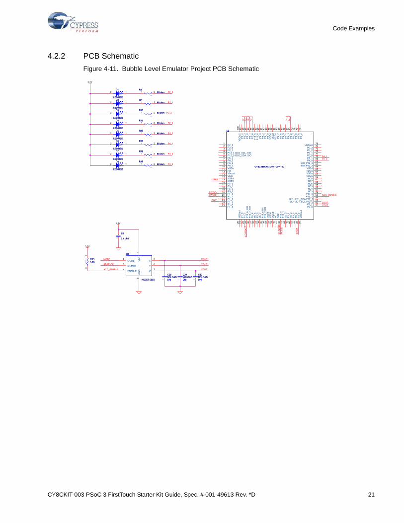
4.3.2 PCB Schematic
Figure 4-14. PCB Schematic for Temperature Sensing Project
This project shows how to detect the position of a finger on the CapSense slider of the PSoC 3 First-Touch Starter Kit board and indicate its position on the LED display.
Running the CapSense project:
1. Connect the PSoC 3 FirstTouch Starter Kit board to the USB port of the PC through the USB cable.
2. Click on the CapSenseSlider example from Kits and Solutions on the startup page of PSoC Creator.
3. Create a folder in the desired location and click OK.
4. The project opens up in PSoC Creator and is saved in that folder.
5. Follow step 1 to 4 in section 4.1.3 Build, Program, and Run the PSoC Rocks Project on page 14 to program the project into the PSoC 3 FirstTouch Starter Kit board.
6. When the download is complete, remove the PSoC 3 FirstTouch Starter Kit board from the USB port and connect a 9-V DC battery to the battery connector of the PSoC 3 FirstTouch Starter Kit board.
7. Move your finger along the CapSense Slider and see the corresponding LEDs light up.
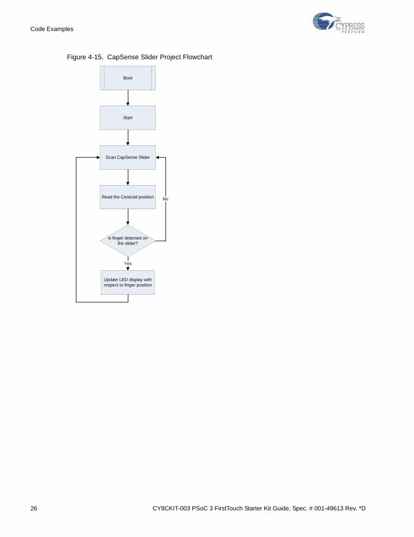
4.4.1 How the CapSense Slider Project Works
Capacitive sensing determines the presence of a conductive element, such as the finger, on acapacitive sensor incorporated on the PCB. The kit consists of a bank of CapSense sensors in theform of a slider. The size of the sensors and their position is designed such that when a finger isplaced on any part of the slider, at least three sensors are active (it detects the presence of the fingerby a change in its capacitance value).
The CapSense component provides APIs, which report the centroid (relative position) of the fingeron the slider based on the active sensors. The firmware then lights up the LED corresponding to thiscentroid position.
This project senses the presence of a finger near the proximity detection antenna. The number ofLEDs that light up on the LED display on the PSoC 3 FirstTouch Starter Kit board increases as thefinger gets closer to the antenna.
To run the proximity sensor project, follow these steps:
1. Connect the PSoC 3 FirstTouch Starter Kit board to the USB port of the PC through the USB cable.
2. Click on the ProximitySensor example from Kits and Solutions on the startup page of PSoC Creator.
3. Create a folder in the desired location and click OK.
4. The project opens up in PSoC Creator and is saved in that folder.
5. Follow step 1 to 4 in section 4.1.3 Build, Program, and Run the PSoC Rocks Project on page 14 to program the project into the PSoC 3 FirstTouch Starter Kit board.
6. When the download is complete, remove the PSoC 3 FirstTouch Starter Kit board from the USB port.
7. Attach the wire antenna to the board at the proximity sensor connector and connect the 9-V DC battery to the battery connector of the PSoC 3 FirstTouch Starter Kit board.
8. Move your finger near and away from the proximity antenna. When your finger comes closer to the antenna, the number of LEDs that light up increases. When it does not sense your finger or hand near the antenna, all the LEDs are turned off.
Figure 4-17. Wire Antenna attached to Proximity Sensor Connector
Proximity detection is performed by a proximity antenna acting as a capacitive sensor. The proximityantenna consists of a wire connected to the proximity connector on the board.
Upon power up, the board establishes a baseline capacitance value of the board along with theantenna attached to it. This is used as a reference value of capacitance and is called the parasiticcapacitance of the board.
When a conductive object, such as a human finger, is brought close to the antenna, the overallcapacitance of the board changes. This change in capacitance determines the proximity of the fingerto the antenna. An increase in capacitance corresponds to the finger being closer to the antenna.
This is used to light up the LEDs based on the proximity of the finger to the antenna. The number ofLEDs turned on increases as the proximity of the finger increases.
To establish the parasitic capacitance, the antenna must be connected to the board before power up.The baseline for capacitive sensors is updated continuously by the firmware. This accounts for anychanges in environmental conditions during the operation.
There are two jumpers on the PCB to set the power configuration, J1 and J4. These jumpers selectthe source for powering the PSoC 3. The options are to power the PSoC 3 from the on board 3.3-Vregulator, to run the PSoC 3 from the USB connector, or to supply power from off board using the J2/J3 connectors.
J4 is to select the power source to drive the 3.3-V regulator. This regulator can be used to powereverything on the board or just the accelerometer. The regulator cannot be powered independentlyfrom the VDDIO bus. It must either power the VDDIO bus or be powered by it.
J1 is to select the power source of the PSoC 3. The I/O cells of the PSoC 3 are driven by this sourcelevel. Only the I/O cells that the accelerometer is connected to remain connected to 3.3 V and mustpower up with the VDDIO bus or after the VDDIO power bus.