Page 1
5/13/2018 CY8CKIT-014_PSoC 5 First Touch Starter Kit_Guide - slidepdf.com
http://slidepdf.com/reader/full/cy8ckit-014psoc-5-first-touch-starter-kitguide 1/44
CY8CKIT-014
PSoC® 5 FirstTouch™ Starter Kit Guide
Spec. # 001-57708 Rev. *
Cypress Semiconducto198 Champion Cou
San Jose, CA 95134-170
Phone (USA): 800.858.181Phone (Intnl): 408.943.260
http://www.cypress.com
Page 2
5/13/2018 CY8CKIT-014_PSoC 5 First Touch Starter Kit_Guide - slidepdf.com
http://slidepdf.com/reader/full/cy8ckit-014psoc-5-first-touch-starter-kitguide 2/44
2 CY8CKIT-014 PSoC 5 FirstTouch Starter Kit Guide, Spec. # 001-57708 Rev. **
Copyrights
Copyrights
© Cypress Semiconductor Corporation, 2010. The information contained herein is subject to change without notice. Cypress
Semiconductor Corporation assumes no responsibility for the use of any circuitry other than circuitry embodied in a Cypress
product. Nor does it convey or imply any license under patent or other rights. Cypress products are not warranted nor
intended to be used for medical, life support, life saving, critical control or safety applications, unless pursuant to an express
written agreement with Cypress. Furthermore, Cypress does not authorize its products for use as critical components in life-
support systems where a malfunction or failure may reasonably be expected to result in significant injury to the user. The
inclusion of Cypress products in life-support systems application implies that the manufacturer assumes all risk of such use
and in doing so indemnifies Cypress against all charges.
Any Source Code (software and/or firmware) is owned by Cypress Semiconductor Corporation (Cypress) and is protected by
and subject to worldwide patent protection (United States and foreign), United States copyright laws and international treaty
provisions. Cypress hereby grants to licensee a personal, non-exclusive, non-transferable license to copy, use, modify, create
derivative works of, and compile the Cypress Source Code and derivative works for the sole purpose of creating custom soft-
ware and or firmware in support of licensee product to be used only in conjunction with a Cypress integrated circuit as speci-
fied in the applicable agreement. Any reproduction, modification, translation, compilation, or representation of this Source
Code except as specified above is prohibited without the express written permission of Cypress.
Disclaimer: CYPRESS MAKES NO WARRANTY OF ANY KIND, EXPRESS OR IMPLIED, WITH REGARD TO THIS MATE-
RIAL, INCLUDING, BUT NOT LIMITED TO, THE IMPLIED WARRANTIES OF MERCHANTABILITY AND FITNESS FOR A
PARTICULAR PURPOSE. Cypress reserves the right to make changes without further notice to the materials describedherein. Cypress does not assume any liability arising out of the application or use of any product or circuit described herein.
Cypress does not authorize its products for use as critical components in life-support systems where a malfunction or failure
may reasonably be expected to result in significant injury to the user. The inclusion of Cypress’ product in a life-support sys-
tems application implies that the manufacturer assumes all risk of such use and in doing so indemnifies Cypress against all
charges.
Use may be limited by and subject to the applicable Cypress software license agreement.
PSoC Designer™, and Programmable System-on-Chip™ are trademarks and PSoC® is a registered trademark of Cypress
Semiconductor Corp. All other trademarks or registered trademarks referenced herein are property of the respective corpora-
tions.
Flash Code Protection
Cypress products meet the specifications contained in their particular Cypress PSoC Data Sheets. Cypress believes that its
family of PSoC products is one of the most secure families of its kind on the market today, regardless of how they are used.
There may be methods, unknown to Cypress, that can breach the code protection features. Any of these methods, to our
knowledge, would be dishonest and possibly illegal. Neither Cypress nor any other semiconductor manufacturer can guaran-
tee the security of their code. Code protection does not mean that we are guaranteeing the product as "unbreakable."
Cypress is willing to work with the customer who is concerned about the integrity of their code. Code protection is constantly
evolving. We at Cypress are committed to continuously improving the code protection features of our products.
Page 3
5/13/2018 CY8CKIT-014_PSoC 5 First Touch Starter Kit_Guide - slidepdf.com
http://slidepdf.com/reader/full/cy8ckit-014psoc-5-first-touch-starter-kitguide 3/44
CY8CKIT-014 PSoC 5 FirstTouch Starter Kit Guide, Spec. # 001-57708 Rev. **
Contents
1. Introduction
1.1 Welcome.....................................................................................................................
1.2 Kit Contents ................................................................................................................1.3 Document Revision History .......................................................................................
1.4 Documentation Conventions ......................................................................................
2. Getting Started
2.1 Hardware ....................................................................................................................
3. Installation
3.1 Install Hardware..........................................................................................................
3.1.1 Hardware Jumpers..........................................................................................3.2 Install Software ..........................................................................................................1
4. Example Projects 1
4.1 PSoC Rocks, PSoC Rocks SAR ADC .......................................................................1
4.1.1 Open the PSoC Rocks Project.......................................................................14.1.2 Modify the PSoC Rocks Project .....................................................................1
4.1.3 Build, Program, and Run the PSoC Rocks Project ........................................14.1.4 Open and Modify the PSoC Rocks SAR ADC Project ...................................1
4.1.5 Schematic Design PSoC Creator...................................................................1
4.1.6 How the PSoC Rocks and PSoC Rocks SAR ADC Projects Work ................14.1.7 PCB Schematic ..............................................................................................1
4.2 Bubble Level Emulator...............................................................................................2
4.2.1 How the Bubble Level Emulator Project Works .............................................24.2.2 PCB Schematic ..............................................................................................2
4.3 ThermistorTemperatureSense...................................................................................2
4.3.1 How the ThermistorTemperatureSense Project Works ..................................2
4.3.1.1 Temperature Sensing Design Principle ...........................................24.3.2 PCB Schematic ..............................................................................................2
4.4 CapSense Slider........................................................................................................2
4.4.1 How the CapSense Slider Project Works.......................................................24.4.2 PCB Schematic ..............................................................................................2
4.5 Proximity Sensor........................................................................................................24.5.1 How the Proximity Sensor Project Works ......................................................3
4.5.2 PCB Schematic ..............................................................................................3
5. Technical Reference 3
5.1 PSoC 5 FirstTouch Starter Kit Schematic..................................................................35.1.1 Hardware Jumpers.........................................................................................3
5.1.2 Board Layout..................................................................................................35.1.3 Bill of Material (BOM) ....................................................................................3
5.2 PSoC 5 Pin Assignment on PSoC 5 FirstTouch Starter Kit Board ............................4
Page 4
5/13/2018 CY8CKIT-014_PSoC 5 First Touch Starter Kit_Guide - slidepdf.com
http://slidepdf.com/reader/full/cy8ckit-014psoc-5-first-touch-starter-kitguide 4/44
4 CY8CKIT-014 PSoC 5 FirstTouch Starter Kit Guide, Spec. # 001-57708 Rev. **
Contents
Page 5
5/13/2018 CY8CKIT-014_PSoC 5 First Touch Starter Kit_Guide - slidepdf.com
http://slidepdf.com/reader/full/cy8ckit-014psoc-5-first-touch-starter-kitguide 5/44
CY8CKIT-014 PSoC 5 FirstTouch Starter Kit Guide, Spec. # 001-57708 Rev. **
1. Introduction
1.1 Welcome
Thank you for purchasing the CY8CKIT-014 PSoC® 5 FirstTouch™ Starter Kit.
The PSoC 5 FirstTouch Starter Kit is designed to introduce you to the PSoC programmable system
on-chip design methodology and Cypress's new PSoC 5 architecture. This full-featured starter k
ships with an array of sensors, I/O's, projects and software to quickly get you up to speed with PSo
Creator and our powerful design methodology so you can easily evaluate PSoC and see wh
values the solution can provide you.
This kit, in addition to our new PSoC 5 architecture, features the following:
■ PSoC Creator development software with an integrated, GCC compiler version 4.2.1
■ USB-based Serial Wire Debugging protocol programmer and debug interface
■ Accelerometer analog sensor
■ Thermistor analog sensor
■ Proximity analog sensor
■ CapSense® analog touch-sensing interface
■ 28-pin general purpose I/O pins
■ 12-pin wireless module header
In this guide you will find instructions on how to easily evaluate the PSoC 5 architecture and PSoCreator design methodology through five included example projects. Experience the developmen
software for yourself and discover how we truly have changed the way you change the world!
If you have questions about or need help with this kit, visit our online technical support center a
http://www.cypress.com/go/support for support options, or contact your local Cypress sale
representative or authorized distributor.
1.2 Kit Contents
PSoC 5 FirstTouch Starter Kit contains:
■ Evaluation Board
■ Quick Start Guide
■ Kit CD
■ USB A to Mini B cable
■ Proximity wire (for use as proximity detection antenna)
■ 9V battery
Page 6
5/13/2018 CY8CKIT-014_PSoC 5 First Touch Starter Kit_Guide - slidepdf.com
http://slidepdf.com/reader/full/cy8ckit-014psoc-5-first-touch-starter-kitguide 6/44
6 CY8CKIT-014 PSoC 5 FirstTouch Starter Kit Guide, Spec. # 001-57708 Rev. **
Introduction
1.3 Document Revision History
1.4 Documentation Conventions
Table 1-1. Revision History
RevisionPDF
Creation Date
Origin of
ChangeDescription of Change
** 05/17/10 SSUT New kit guide.
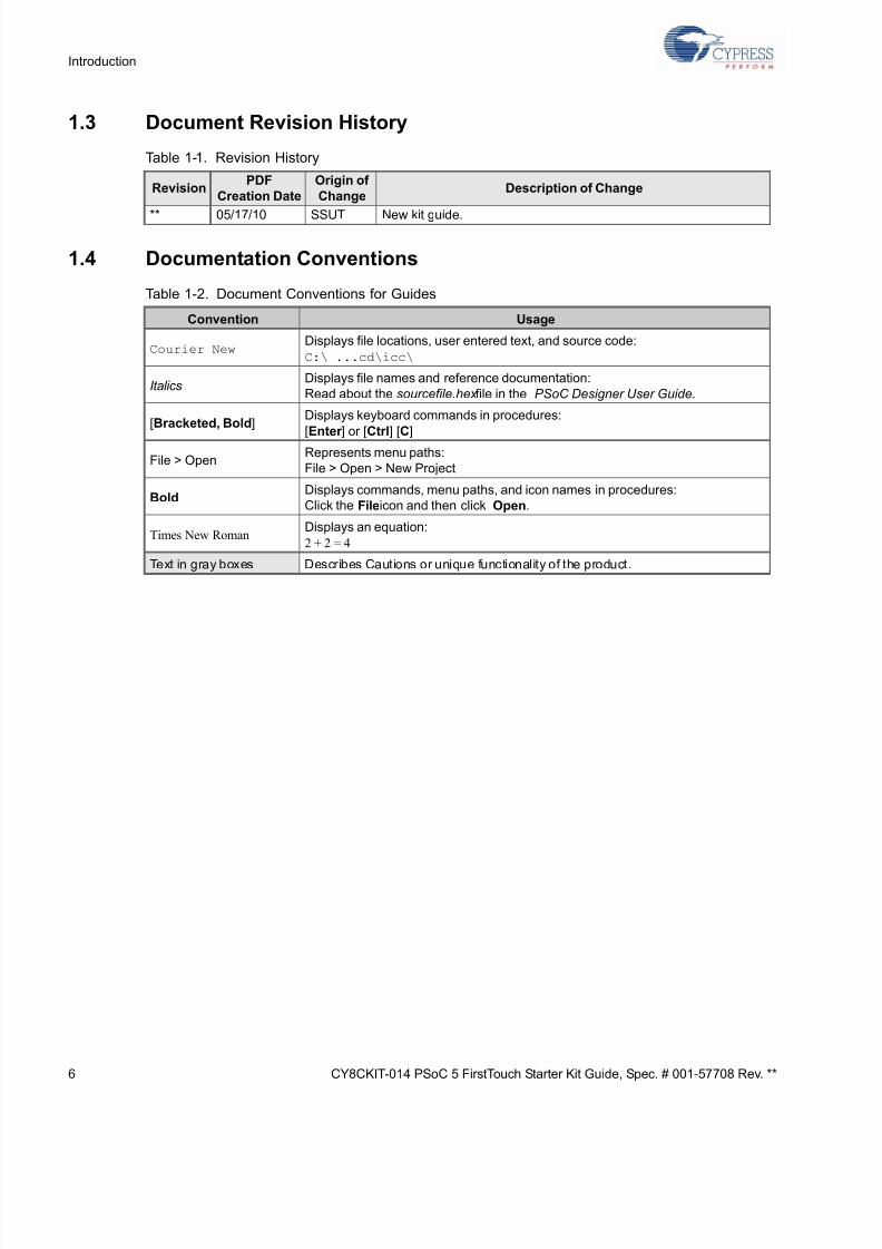
Table 1-2. Document Conventions for Guides
Convention Usage
Courier NewDisplays file locations, user entered text, and source code:
C:\ ...cd\icc\
ItalicsDisplays file names and reference documentation:
Read about the sourcefile.hex file in the PSoC Designer User Guide.
[Bracketed, Bold]Displays keyboard commands in procedures:
[Enter ] or [Ctrl] [C]
File > OpenRepresents menu paths:
File > Open > New Project
BoldDisplays commands, menu paths, and icon names in procedures:
Click the File icon and then click Open.
Times New RomanDisplays an equation:
2 + 2 = 4
Text in gray boxes Describes Cautions or unique functionality of the product.
Page 7
5/13/2018 CY8CKIT-014_PSoC 5 First Touch Starter Kit_Guide - slidepdf.com
http://slidepdf.com/reader/full/cy8ckit-014psoc-5-first-touch-starter-kitguide 7/44
CY8CKIT-014 PSoC 5 FirstTouch Starter Kit Guide, Spec. # 001-57708 Rev. **
2. Getting Started
2.1 Hardware
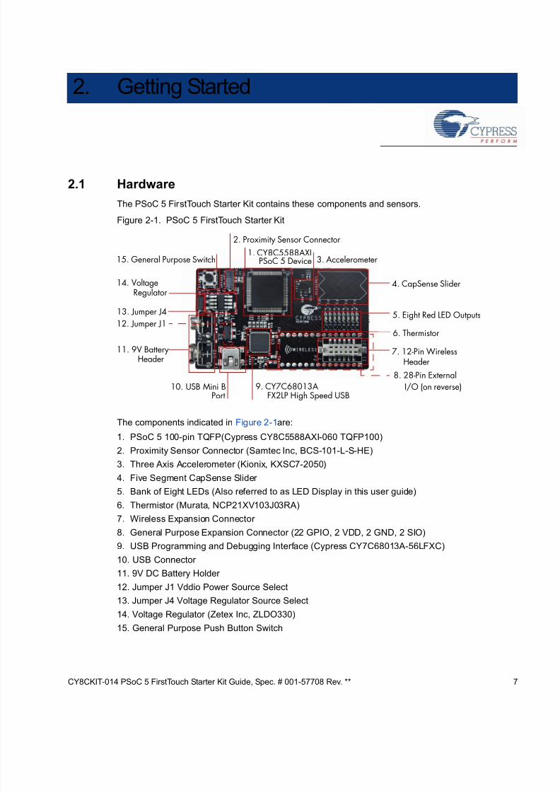
The PSoC 5 FirstTouch Starter Kit contains these components and sensors.
Figure 2-1. PSoC 5 FirstTouch Starter Kit
The components indicated in Figure 2-1 are:
1. PSoC 5 100-pin TQFP(Cypress CY8C5588AXI-060 TQFP100)
2. Proximity Sensor Connector (Samtec Inc, BCS-101-L-S-HE)
3. Three Axis Accelerometer (Kionix, KXSC7-2050)
4. Five Segment CapSense Slider
5. Bank of Eight LEDs (Also referred to as LED Display in this user guide)
6. Thermistor (Murata, NCP21XV103J03RA)
7. Wireless Expansion Connector
8. General Purpose Expansion Connector (22 GPIO, 2 VDD, 2 GND, 2 SIO)
9. USB Programming and Debugging Interface (Cypress CY7C68013A-56LFXC)
10. USB Connector
11. 9V DC Battery Holder
12. Jumper J1 Vddio Power Source Select
13. Jumper J4 Voltage Regulator Source Select
14. Voltage Regulator (Zetex Inc, ZLDO330)
15. General Purpose Push Button Switch
15. General Purpose
2. Proximity Sensor Connector
3. Accelerometer
4. CapSense Slider14. Voltage
11. 9V Battery
10. USB Mini B 9. CY7C68013A8. 28-Pin External
7. 12-Pin Wireless
6. Thermistor
5. Eight Red LED Outputs
Header
FX2LP High Speed USBPortI/O (on reverse)
Header
Regulator
Switch
13. Jumper J4
12. Jumper J1
1. CY8C5588AXIPSoC 5 Device
Page 8
5/13/2018 CY8CKIT-014_PSoC 5 First Touch Starter Kit_Guide - slidepdf.com
http://slidepdf.com/reader/full/cy8ckit-014psoc-5-first-touch-starter-kitguide 8/44
8 CY8CKIT-014 PSoC 5 FirstTouch Starter Kit Guide, Spec. # 001-57708 Rev. **
Getting Started
Page 9
5/13/2018 CY8CKIT-014_PSoC 5 First Touch Starter Kit_Guide - slidepdf.com
http://slidepdf.com/reader/full/cy8ckit-014psoc-5-first-touch-starter-kitguide 9/44
CY8CKIT-014 PSoC 5 FirstTouch Starter Kit Guide, Spec. # 001-57708 Rev. **
3. Installation
3.1 Install Hardware
This section shows you how to use the PSoC 5 FirstTouch Starter Kit.
Note: This kit comes with a factory programmed demonstration to display "PSoC Rocks!" messag
on the LED display when the board is waved.
1. Unpack the PSoC 5 FirstTouch Starter Kit.
2. Connect a 9V DC battery to the battery connector on the kit board.
3. Hold the board and battery exposing the LEDs. Then continuously wave the board from side toside in the plane of the PCB (shown in Figure 3-1).
4. As you wave the board, the rasterized image of the message "PSoC Rocks!" appears as shown
in the following figure.
5. Keep waving. The message changes every few seconds.
Figure 3-1. Rasterized Image of "PSoC Rocks!"
3.1.1 Hardware Jumpers
There are two jumpers for power configuration. All examples are run with the default setup of 3.3
operation. This requires J1-2 to connect to J1-3 and J4-2 to connect to J4-3. For all other configura
tions see section 5.1.1 Hardware Jumpers on page 35.
Page 10
5/13/2018 CY8CKIT-014_PSoC 5 First Touch Starter Kit_Guide - slidepdf.com
http://slidepdf.com/reader/full/cy8ckit-014psoc-5-first-touch-starter-kitguide 10/44
10 CY8CKIT-014 PSoC 5 FirstTouch Starter Kit Guide, Spec. # 001-57708 Rev. **
Installation
3.2 Install Software
When installing the PSoC 5 FirstTouch Starter Kit, the installer checks if the prerequisites, PSoC
Creator, PSoC Programmer, Windows Installer, Windows.NET, Acrobat Reader, and GCC compiler
version 4.2.1, are installed in your PC. If these applications are not installed, then the installer
prompts you to install them.
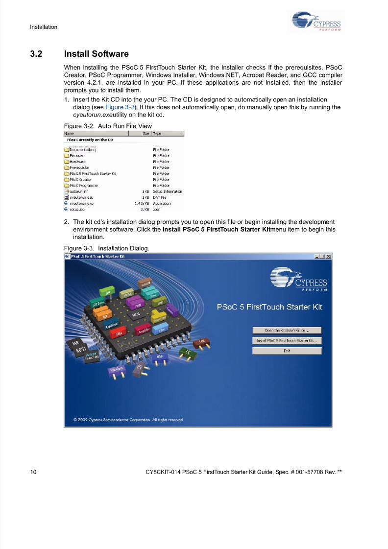
1. Insert the Kit CD into the your PC. The CD is designed to automatically open an installation
dialog (see Figure 3-3). If this does not automatically open, do manually open this by running the
cyautorun.exe utility on the kit cd.
Figure 3-2. Auto Run File View
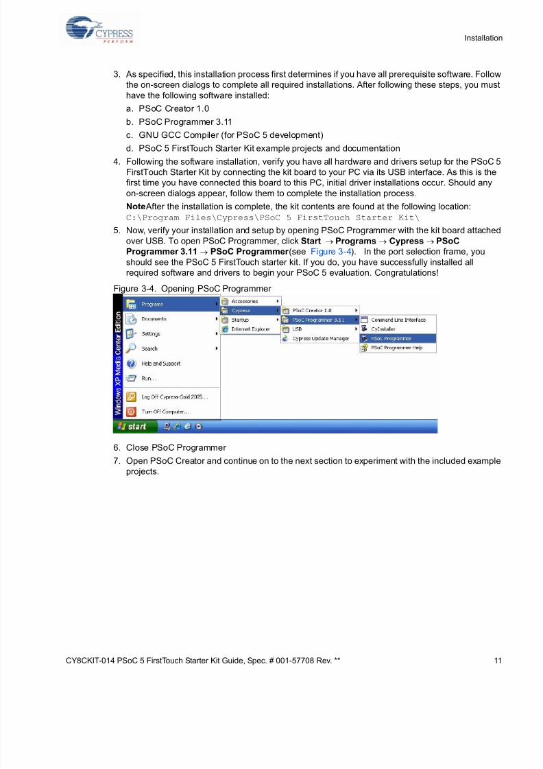
2. The kit cd's installation dialog prompts you to open this file or begin installing the development
environment software. Click the Install PSoC 5 FirstTouch Starter Kit menu item to begin this
installation.
Figure 3-3. Installation Dialog.
Page 11
5/13/2018 CY8CKIT-014_PSoC 5 First Touch Starter Kit_Guide - slidepdf.com
http://slidepdf.com/reader/full/cy8ckit-014psoc-5-first-touch-starter-kitguide 11/44
CY8CKIT-014 PSoC 5 FirstTouch Starter Kit Guide, Spec. # 001-57708 Rev. ** 1
Installatio
3. As specified, this installation process first determines if you have all prerequisite software. Follow
the on-screen dialogs to complete all required installations. After following these steps, you mus
have the following software installed:
a. PSoC Creator 1.0
b. PSoC Programmer 3.11
c. GNU GCC Compiler (for PSoC 5 development)
d. PSoC 5 FirstTouch Starter Kit example projects and documentation
4. Following the software installation, verify you have all hardware and drivers setup for the PSoC
FirstTouch Starter Kit by connecting the kit board to your PC via its USB interface. As this is the
first time you have connected this board to this PC, initial driver installations occur. Should any
on-screen dialogs appear, follow them to complete the installation process.
Note After the installation is complete, the kit contents are found at the following location:
C:\Program Files\Cypress\PSoC 5 FirstTouch Starter Kit\
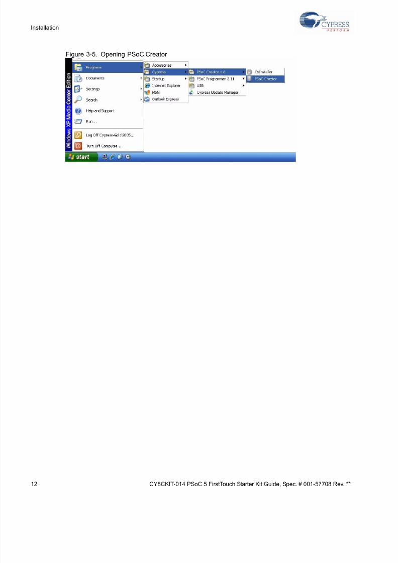
5. Now, verify your installation and setup by opening PSoC Programmer with the kit board attache
over USB. To open PSoC Programmer, click Start →Programs→ Cypress→PSoC
Programmer 3.11→ PSoC Programmer (see Figure 3-4). In the port selection frame, you
should see the PSoC 5 FirstTouch starter kit. If you do, you have successfully installed all
required software and drivers to begin your PSoC 5 evaluation. Congratulations!
Figure 3-4. Opening PSoC Programmer
6. Close PSoC Programmer
7. Open PSoC Creator and continue on to the next section to experiment with the included exampl
projects.
Page 12
5/13/2018 CY8CKIT-014_PSoC 5 First Touch Starter Kit_Guide - slidepdf.com
http://slidepdf.com/reader/full/cy8ckit-014psoc-5-first-touch-starter-kitguide 12/44
12 CY8CKIT-014 PSoC 5 FirstTouch Starter Kit Guide, Spec. # 001-57708 Rev. **
Installation
Figure 3-5. Opening PSoC Creator
Page 13
5/13/2018 CY8CKIT-014_PSoC 5 First Touch Starter Kit_Guide - slidepdf.com
http://slidepdf.com/reader/full/cy8ckit-014psoc-5-first-touch-starter-kitguide 13/44
CY8CKIT-014 PSoC 5 FirstTouch Starter Kit Guide, Spec. # 001-57708 Rev. ** 1
4. Example Projects
4.1 PSoC Rocks, PSoC Rocks SAR ADC
The PSoC Rocks project displays a rasterized image of the user defined message ("PSoC Rocks!
using persistence of vision. Waving the circuit board back and forth quickly in the plane of the boar
generates the message. PSoC 5 FirstTouch Starter Kit is factory programmed with PSoC Rock
SAR ADC project. This project is similar to PSoC Rocks project. The difference is PSoC Rocks SA
ADC project uses SAR ADC, and PSoC Rocks project uses Delta Sigma ADC
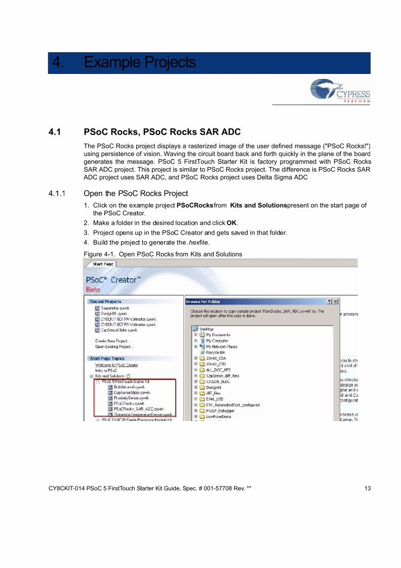
4.1.1 Open the PSoC Rocks Project
1. Click on the example project PSoCRocks from Kits and Solutions present on the start page o
the PSoC Creator.
2. Make a folder in the desired location and click OK.
3. Project opens up in the PSoC Creator and gets saved in that folder.
4. Build the project to generate the .hex file.
Figure 4-1. Open PSoC Rocks from Kits and Solutions
Page 14
5/13/2018 CY8CKIT-014_PSoC 5 First Touch Starter Kit_Guide - slidepdf.com
http://slidepdf.com/reader/full/cy8ckit-014psoc-5-first-touch-starter-kitguide 14/44
14 CY8CKIT-014 PSoC 5 FirstTouch Starter Kit Guide, Spec. # 001-57708 Rev. **
Example Projects
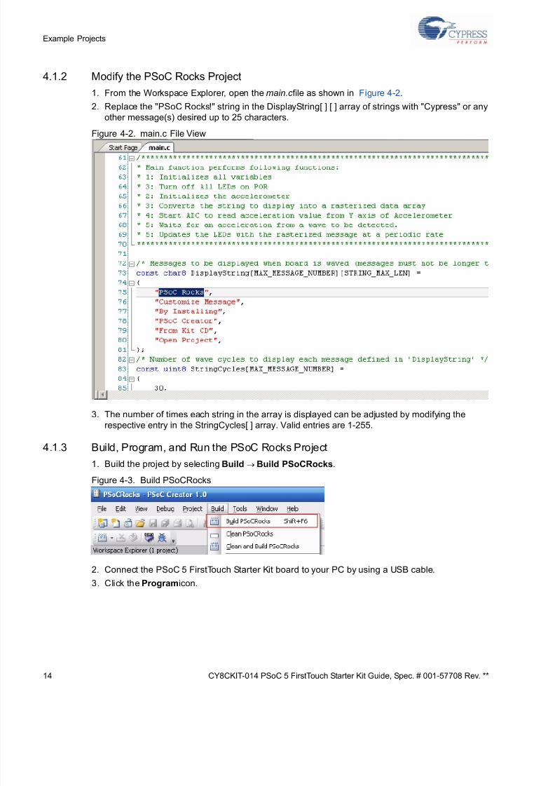
4.1.2 Modify the PSoC Rocks Project
1. From the Workspace Explorer, open the main.c file as shown in Figure 4-2.
2. Replace the "PSoC Rocks!" string in the DisplayString[ ] [ ] array of strings with "Cypress" or any
other message(s) desired up to 25 characters.
Figure 4-2. main.c File View
3. The number of times each string in the array is displayed can be adjusted by modifying therespective entry in the StringCycles[ ] array. Valid entries are 1-255.
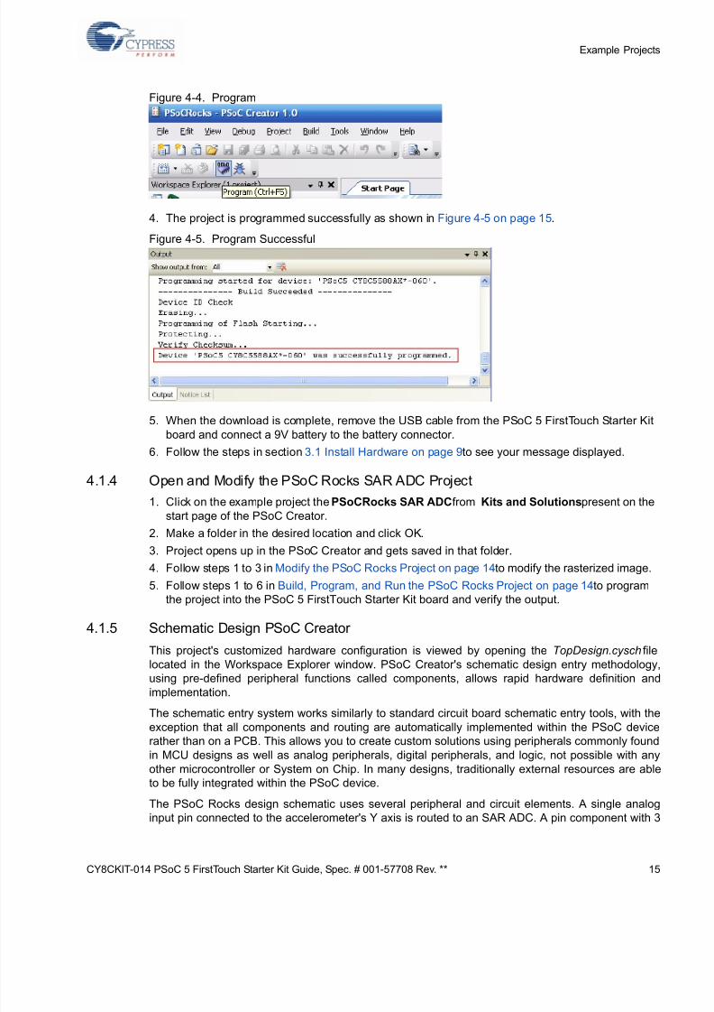
4.1.3 Build, Program, and Run the PSoC Rocks Project
1. Build the project by selecting Build →Build PSoCRocks.
Figure 4-3. Build PSoCRocks
2. Connect the PSoC 5 FirstTouch Starter Kit board to your PC by using a USB cable.
3. Click the Program icon.
Page 15
5/13/2018 CY8CKIT-014_PSoC 5 First Touch Starter Kit_Guide - slidepdf.com
http://slidepdf.com/reader/full/cy8ckit-014psoc-5-first-touch-starter-kitguide 15/44
CY8CKIT-014 PSoC 5 FirstTouch Starter Kit Guide, Spec. # 001-57708 Rev. ** 1
Example Projec
Figure 4-4. Program
4. The project is programmed successfully as shown in Figure 4-5 on page 15.
Figure 4-5. Program Successful
5. When the download is complete, remove the USB cable from the PSoC 5 FirstTouch Starter Kit
board and connect a 9V battery to the battery connector.
6. Follow the steps in section 3.1 Install Hardware on page 9 to see your message displayed.
4.1.4 Open and Modify the PSoC Rocks SAR ADC Project
1. Click on the example project the PSoCRocks SAR ADC from Kits and Solutions present on th
start page of the PSoC Creator.
2. Make a folder in the desired location and click OK.
3. Project opens up in the PSoC Creator and gets saved in that folder.
4. Follow steps 1 to 3 in Modify the PSoC Rocks Project on page 14 to modify the rasterized image
5. Follow steps 1 to 6 in Build, Program, and Run the PSoC Rocks Project on page 14 to program
the project into the PSoC 5 FirstTouch Starter Kit board and verify the output.
4.1.5 Schematic Design PSoC Creator
This project's customized hardware configuration is viewed by opening the TopDesign.cysch fi
located in the Workspace Explorer window. PSoC Creator's schematic design entry methodolog
using pre-defined peripheral functions called components, allows rapid hardware definition an
implementation.
The schematic entry system works similarly to standard circuit board schematic entry tools, with th
exception that all components and routing are automatically implemented within the PSoC devic
rather than on a PCB. This allows you to create custom solutions using peripherals commonly foun
in MCU designs as well as analog peripherals, digital peripherals, and logic, not possible with an
other microcontroller or System on Chip. In many designs, traditionally external resources are ab
to be fully integrated within the PSoC device.
The PSoC Rocks design schematic uses several peripheral and circuit elements. A single analo
input pin connected to the accelerometer's Y axis is routed to an SAR ADC. A pin component with
Page 16
5/13/2018 CY8CKIT-014_PSoC 5 First Touch Starter Kit_Guide - slidepdf.com
http://slidepdf.com/reader/full/cy8ckit-014psoc-5-first-touch-starter-kitguide 16/44
16 CY8CKIT-014 PSoC 5 FirstTouch Starter Kit Guide, Spec. # 001-57708 Rev. **
Example Projects
pins is used to control the functionality of the accelerometer and another pair is used to drive the
LEDs. The last schematic element is a control register that is used to drive the LED pins. The control
register output is inverted to sink current from the LEDs. This allows the LEDs to be driven externally
with the highest possible current and brightness without adding complexity to the design.
Conventional systems would require firmware overhead to decode and invert the data for each of the
affected LED pins.
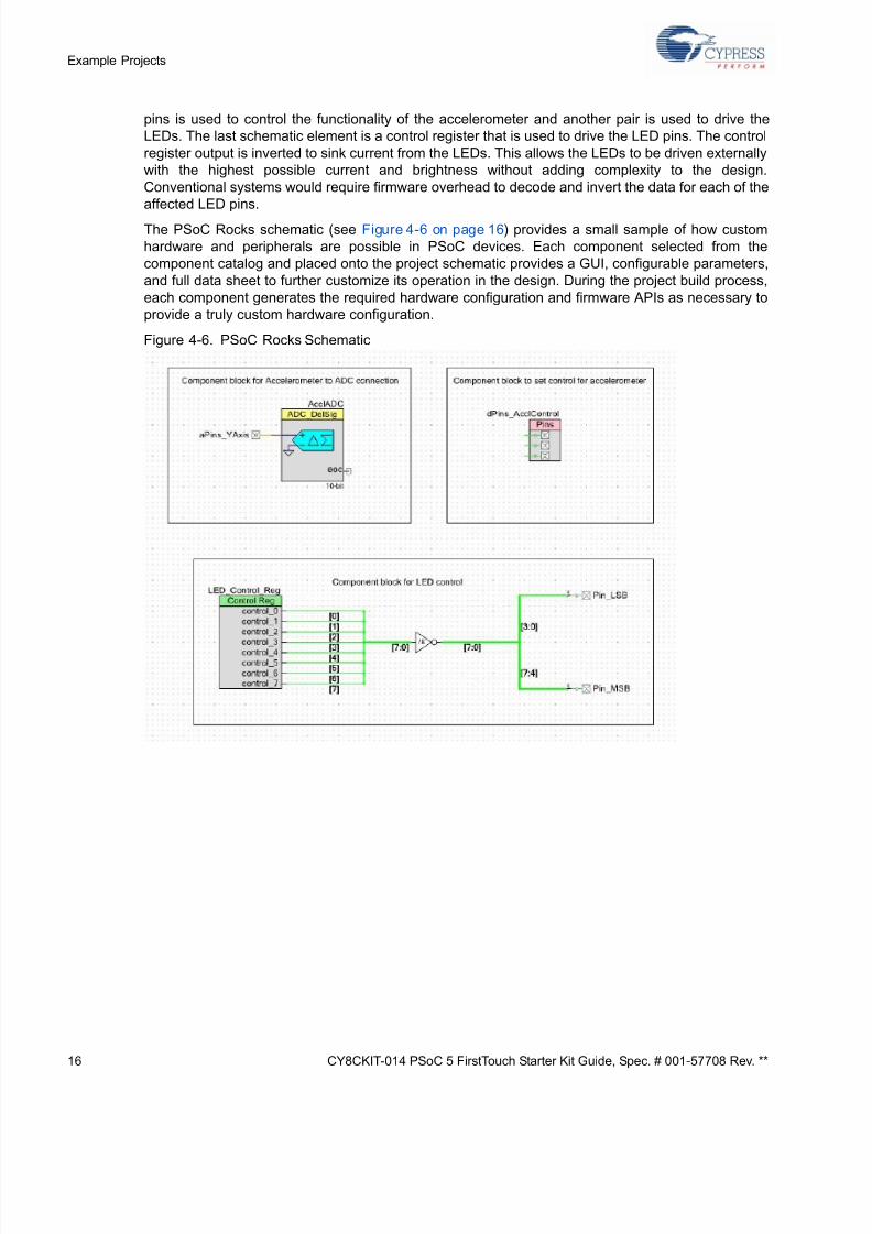
The PSoC Rocks schematic (see Figure 4-6 on page 16) provides a small sample of how custom
hardware and peripherals are possible in PSoC devices. Each component selected from the
component catalog and placed onto the project schematic provides a GUI, configurable parameters,
and full data sheet to further customize its operation in the design. During the project build process,
each component generates the required hardware configuration and firmware APIs as necessary to
provide a truly custom hardware configuration.
Figure 4-6. PSoC Rocks Schematic
Page 17
5/13/2018 CY8CKIT-014_PSoC 5 First Touch Starter Kit_Guide - slidepdf.com
http://slidepdf.com/reader/full/cy8ckit-014psoc-5-first-touch-starter-kitguide 17/44
CY8CKIT-014 PSoC 5 FirstTouch Starter Kit Guide, Spec. # 001-57708 Rev. ** 1
Example Projec
Figure 4-7. PSoC Rocks SAR ADC Schematic
4.1.6 How the PSoC Rocks and PSoC Rocks SAR ADC Projects Work
This example displays a message using a bank of LEDs, that when swung in a back and forth arcin
motion, produces a rasterized character display. The PSoC 5 FirstTouch Starter Kit has a three ax
accelerometer. The accelerometer detects the instantaneous acceleration of the board when
motion. The instantaneous voltage at each axis of the accelerometer is directly proportional to thacceleration along that axis.
In this project, the firmware uses the Y axis voltage output of the accelerometer. This voltage
routed to an ADC in the PSoC. This digital value is now a measure of acceleration detected by th
accelerometer. If the acceleration exceeds a maximum value it signals the start of a new wave even
On start of a new wave the firmware delays for a fixed period of time to start the first character in th
proper position of the wave. The current string is converted into a rasterized display data array prio
to the start of the wave. Each column of the rasterized data array is sequentially output after a fixe
delay. The delay periods may be adjusted in firmware.
For a particular character in the message, a look up table determines which LEDs to turn on. Whe
the board is waved back and forth rapidly, due to persistence of vision, the user defined imag
appears to float in the air. Multiple strings may be configured with each string being displayed for a
adjustable number of wave cycles.
Page 18
5/13/2018 CY8CKIT-014_PSoC 5 First Touch Starter Kit_Guide - slidepdf.com
http://slidepdf.com/reader/full/cy8ckit-014psoc-5-first-touch-starter-kitguide 18/44
18 CY8CKIT-014 PSoC 5 FirstTouch Starter Kit Guide, Spec. # 001-57708 Rev. **
Example Projects
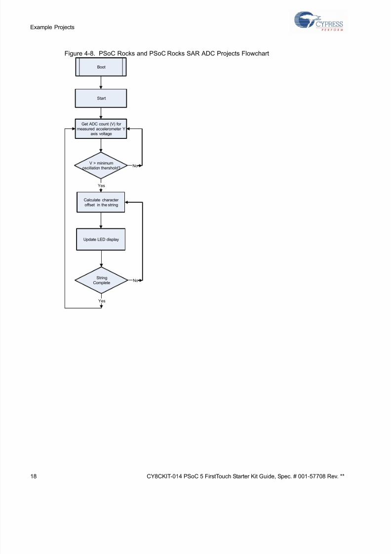
Figure 4-8. PSoC Rocks and PSoC Rocks SAR ADC Projects Flowchart
Boot
Start
Get ADC count (V) for
measured accelerometer Yaxis voltage
V > minimumoscillation thershold?
Calculate character
offset in the string
Update LED display
No
Yes
String
CompleteNo
Yes
Page 19
5/13/2018 CY8CKIT-014_PSoC 5 First Touch Starter Kit_Guide - slidepdf.com
http://slidepdf.com/reader/full/cy8ckit-014psoc-5-first-touch-starter-kitguide 19/44
CY8CKIT-014 PSoC 5 FirstTouch Starter Kit Guide, Spec. # 001-57708 Rev. ** 1
Example Projec
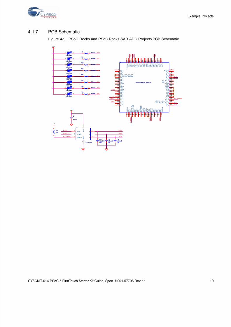
4.1.7 PCB Schematic
Figure 4-9. PSoC Rocks and PSoC Rocks SAR ADC Projects PCB Schematic
P2_0
P4_3
P4_2
P4_1
P4_0
P2_3
P2_2
P2_1
ACC_ENABLE
P4_0
SWDCK
P 2_
1
X O U T
P 2_
3
ZOUTSWV
P4_1
P 4_
3
L O W B A T T
P 4_
2
SWDIO
S T / M O D E
M O D E
/XRES
P 2_
0
P 2_
2
YOUT
MODE
ACC_ENABLE
ST/MODE
ZOUT
YOUT
XOUT
3.3V
3.3V
3.3V
0402
DNI
C29NOLOAD
0402
DNI
C29NOLOAD
0 4 0 2
R1768 ohm
0 4 0 2
R1768 ohm1 2
0603
D1
LED RED
0603
D1
LED RED
2 1
0402
C1
0.1 uFd0402
C1
0.1 uFd
0603
D5
LED RED
0603
D5
LED RED
2 1
0 4 0 2
R1868 ohm
0 4 0 2
R1868 ohm1 2
U1
KXSC7-2050
U1
KXSC7-2050
V D D
1
MODE2
ST/MOT3
ENABLE4
X5
Y6
Z7
G N D
8
0 4 0 2
R1968 ohm
0 4 0 2
R1968 ohm1 2
0402
DNI
C30NOLOAD
0402
DNI
C30NOLOAD
0603
D7
LED RED
0603
D7
LED RED
2 1
0603
D2
LED RED
0603
D2
LED RED
2 1
U2
CY8C5588AXI-060 TQFP100
U2
CY8C5588AXI-060 TQFP100
P2_51
P2_62
P2_73
P12_4 I2C0_SCL, SIO4
P12_5 I2C0_SDA, SIO5
P6_46
P6_57
P6_68
P6_79
VSSb10
Ind11
Vboost12
Vbat13
VSSd14
XRES15
P5_016
P5_117
P5_218
P5_319
P1_020
P1_121
P1_222
P1_323
P1_424
P1_525
V D D i o 1
2 6
P 1_
6
2 7
P 1_
7
2 8
P 1 2_
6_
S I O
2 9
P 1 2_
7_
S I O
3 0
P 5_
4
3 1
P 5_
5
3 2
P 5_
6
3 3
P 5_
7
3 4
P 1 5_
6 D P
3 5
P 1 5_
7 D M
3 6
V D D d
3 7
V S S d
3 8
V C C d
3 9
N C 1
4 0
N C 2
4 1
P 1 5_
0
4 2
P 1 5_
1
4 3
P 3_
0
4 4
P 3_
1
4 5
P 3_
2
4 6
P 3_
3
4 7
P 3_
4
4 8
P 3_
5
4 9
V D D i o 3
5 0
VDDio075
P0_374
P0_273
P0_172
P0_071
P4_170
P4_069
SIO_P12_368
SIO_P12_267
VSSd66
VDDa65
VSSa64
VCCa63
NC862
NC761
NC660
NC559
NC458
NC357
P15_356
P15_255
SIO, I2C1_SDA P12_154
SIO, I2C1_SCL P12_053
P3_752
P3_651
P 2_
4
9 9
P 2_
3
9 8
P 2_
2
9 7
P 2_
1
9 6
P 2_
0
9 5
P 1 5_
5
9 4
P 1 5_
4
9 3
P 6_
3
9 2
P 6_
2
9 1
P 6_
1
9 0
P 6_
0
8 9
V D D d
8 8
V S S d
8 7
V C C d
8 6
P 4_
7
8 5
P 4_
6
8 4
P 4_
5
8 3
P 4_
4
8 2
P 4_
3
8 1
P 4_
2
8 0
P 0_
7
7 9
P 0_
6
7 8
P 0_
5
7 7
P 0_
4
7 6
V D D i o 2
1 0 0
0603
D4
LED RED
0603
D4
LED RED
2 1
0 4 0 2
R768 ohm
0 4 0 2
R768 ohm1 2
0603
D6
LED RED
0603
D6
LED RED
2 1
0402
DNI
C25NOLOAD
0402
DNI
C25NOLOAD
0 4 0 2
R1068 ohm
0 4 0 2
R1068 ohm1 2
0 4 0 2
R268 ohm
0 4 0 2
R268 ohm1 2
0 4 0 2
R1368 ohm
0 4 0 2
R1368 ohm1 2
0 4 0 2
R351.5K 0
4 0 2
R351.5K
1
2
0603
D8
LED RED
0603
D8
LED RED
2 1
0 4 0 2
R1668 ohm
0 4 0 2
R1668 ohm1 2
0603
D3
LED RED
0603
D3
LED RED
2 1
Page 20
5/13/2018 CY8CKIT-014_PSoC 5 First Touch Starter Kit_Guide - slidepdf.com
http://slidepdf.com/reader/full/cy8ckit-014psoc-5-first-touch-starter-kitguide 20/44
20 CY8CKIT-014 PSoC 5 FirstTouch Starter Kit Guide, Spec. # 001-57708 Rev. **
Example Projects
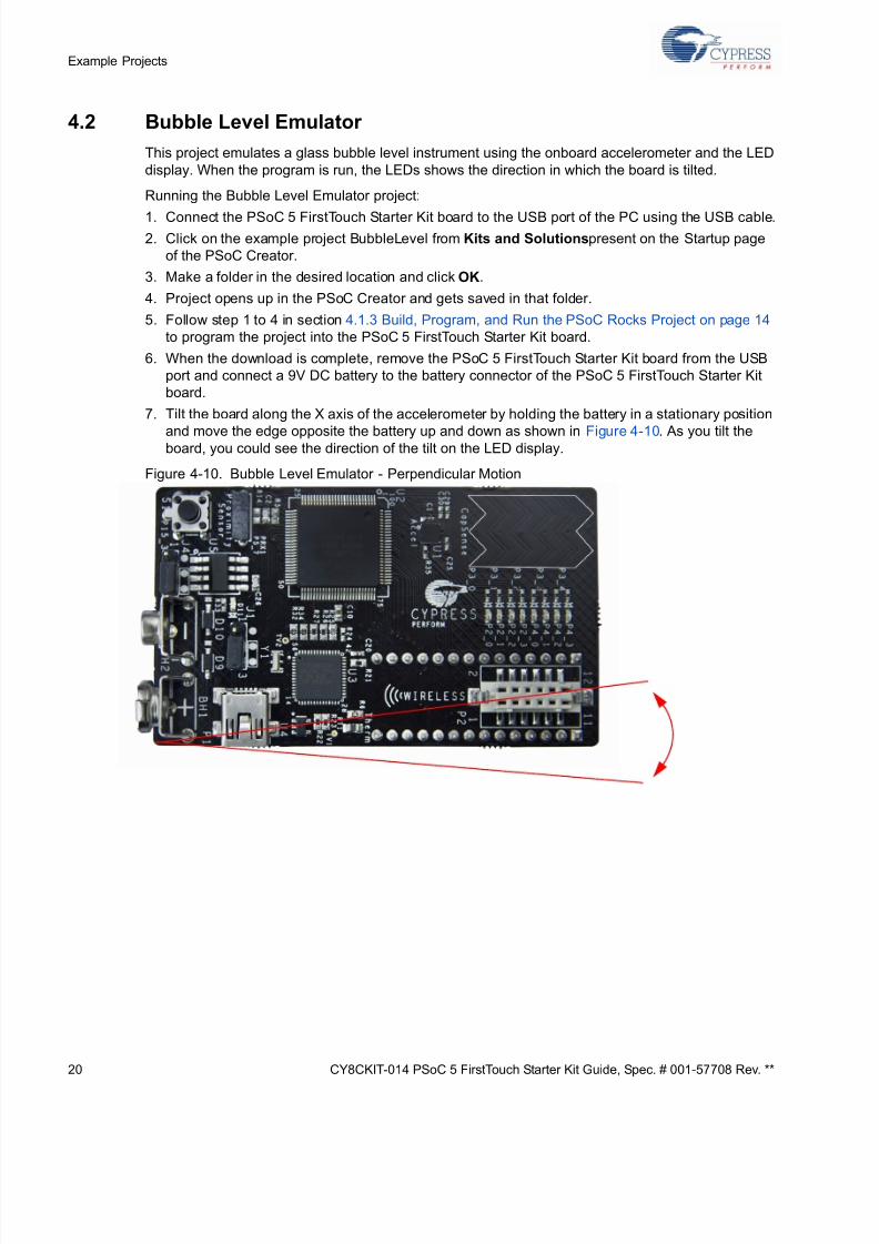
4.2 Bubble Level Emulator
This project emulates a glass bubble level instrument using the onboard accelerometer and the LED
display. When the program is run, the LEDs shows the direction in which the board is tilted.
Running the Bubble Level Emulator project:
1. Connect the PSoC 5 FirstTouch Starter Kit board to the USB port of the PC using the USB cable.2. Click on the example project BubbleLevel from Kits and Solutions present on the Startup page
of the PSoC Creator.
3. Make a folder in the desired location and click OK.
4. Project opens up in the PSoC Creator and gets saved in that folder.
5. Follow step 1 to 4 in section 4.1.3 Build, Program, and Run the PSoC Rocks Project on page 14
to program the project into the PSoC 5 FirstTouch Starter Kit board.
6. When the download is complete, remove the PSoC 5 FirstTouch Starter Kit board from the USB
port and connect a 9V DC battery to the battery connector of the PSoC 5 FirstTouch Starter Kit
board.
7. Tilt the board along the X axis of the accelerometer by holding the battery in a stationary position
and move the edge opposite the battery up and down as shown in Figure 4-10. As you tilt theboard, you could see the direction of the tilt on the LED display.
Figure 4-10. Bubble Level Emulator - Perpendicular Motion
Page 21
5/13/2018 CY8CKIT-014_PSoC 5 First Touch Starter Kit_Guide - slidepdf.com
http://slidepdf.com/reader/full/cy8ckit-014psoc-5-first-touch-starter-kitguide 21/44
CY8CKIT-014 PSoC 5 FirstTouch Starter Kit Guide, Spec. # 001-57708 Rev. ** 2
Example Projec
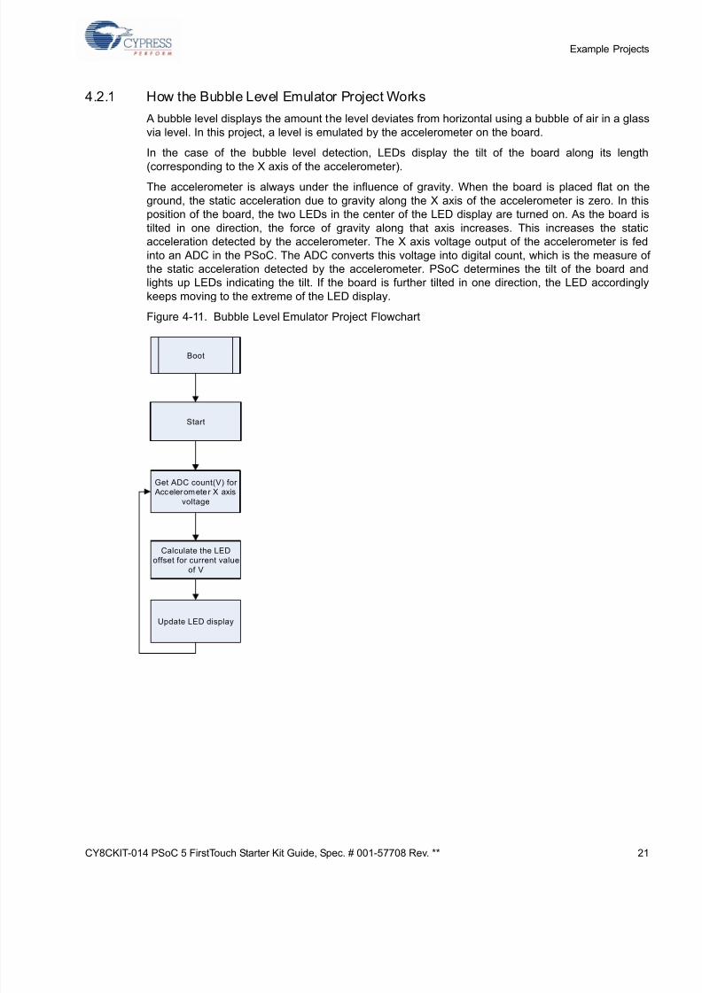
4.2.1 How the Bubble Level Emulator Project Works
A bubble level displays the amount the level deviates from horizontal using a bubble of air in a glas
via level. In this project, a level is emulated by the accelerometer on the board.
In the case of the bubble level detection, LEDs display the tilt of the board along its lengt
(corresponding to the X axis of the accelerometer).
The accelerometer is always under the influence of gravity. When the board is placed flat on th
ground, the static acceleration due to gravity along the X axis of the accelerometer is zero. In th
position of the board, the two LEDs in the center of the LED display are turned on. As the board
tilted in one direction, the force of gravity along that axis increases. This increases the stat
acceleration detected by the accelerometer. The X axis voltage output of the accelerometer is fe
into an ADC in the PSoC. The ADC converts this voltage into digital count, which is the measure
the static acceleration detected by the accelerometer. PSoC determines the tilt of the board an
lights up LEDs indicating the tilt. If the board is further tilted in one direction, the LED according
keeps moving to the extreme of the LED display.
Figure 4-11. Bubble Level Emulator Project Flowchart
Boot
Start
Get ADC count(V) for Accelerometer X axis
voltage
Calculate the LED
offset for current value
of V
Update LED display
Page 22
5/13/2018 CY8CKIT-014_PSoC 5 First Touch Starter Kit_Guide - slidepdf.com
http://slidepdf.com/reader/full/cy8ckit-014psoc-5-first-touch-starter-kitguide 22/44
22 CY8CKIT-014 PSoC 5 FirstTouch Starter Kit Guide, Spec. # 001-57708 Rev. **
Example Projects
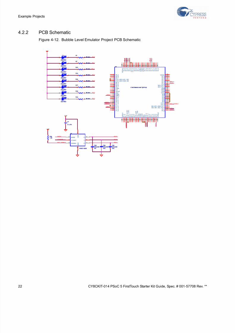
4.2.2 PCB Schematic
Figure 4-12. Bubble Level Emulator Project PCB Schematic
P2_0
P4_3
P4_2
P4_1
P4_0
P2_3
P2_2
P2_1
ACC_ENABLE
P4_0
SWDCK
P 2_ 1
X O U T
P 2_ 3
ZOUTSWV
P4_1
P 4_ 3
L O W B A T T
P 4_ 2
SWDIO
S T / M O D E
M O D E
/XRES
P 2_ 0
P 2_ 2
YOUT
MODE
ACC_ENABLE
ST/MODE
ZOUT
YOUT
XOUT
3.3V
3.3V
3.3V
0 4 0 2
R268 ohm
0 4 0 2
R268 ohm1 2
0603
D7
LED RED
0603
D7
LED RED
2 1
0 4 0 2
R1068 ohm
0 4 0 2
R1068 ohm1 2
0603
D5
LED RED
0603
D5
LED RED
2 1
U2
CY8C5588AXI-060 TQFP100
U2
CY8C5588AXI-060 TQFP100
P2_51
P2_62
P2_73
P12_4 I2C0_SCL, SIO4
P12_5 I2C0_SDA, SIO5
P6_46
P6_57
P6_68
P6_79
VSSb10
Ind11
Vboost12
Vbat13
VSSd14
XRES15
P5_016
P5_117
P5_218
P5_319
P1_020
P1_121
P1_222
P1_323
P1_424
P1_525
V D
D i o 1
2 6
P 1
_ 6
2 7
P 1
_ 7
2 8
P 1
2_
6_
S I O
2 9
P 1
2_
7_
S I O
3 0
P 5
_ 4
3 1
P 5
_ 5
3 2
P 5
_ 6
3 3
P 5
_ 7
3 4
P 1
5_
6 D P
3 5
P 1
5_
7 D M
3 6
V D
D d
3 7
V S
S d
3 8
V C
C d
3 9
N C 1
4 0
N C 2
4 1
P 1
5_
0
4 2
P 1
5_
1
4 3
P 3
_ 0
4 4
P 3
_ 1
4 5
P 3
_ 2
4 6
P 3
_ 3
4 7
P 3
_ 4
4 8
P 3
_ 5
4 9
V D
D i o 3
5 0
VDDio075
P0_374
P0_273
P0_172
P0_071
P4_170
P4_069
SIO_P12_368
SIO_P12_267
VSSd66
VDDa65
VSSa64
VCCa63
NC862
NC761
NC660
NC559
NC458
NC357
P15_356
P15_255
SIO, I2C1_SDA P12_154
SIO, I2C1_SCL P12_053
P3_752
P3_651
P 2_
4
9 9
P 2_
3
9 8
P 2_
2
9 7
P 2_
1
9 6
P 2_
0
9 5
P 1 5_
5
9 4
P 1 5_
4
9 3
P 6_
3
9 2
P 6_
2
9 1
P 6_
1
9 0
P 6_
0
8 9
V D D d
8 8
V S S d
8 7
V C C d
8 6
P 4_
7
8 5
P 4_
6
8 4
P 4_
5
8 3
P 4_
4
8 2
P 4_
3
8 1
P 4_
2
8 0
P 0_
7
7 9
P 0_
6
7 8
P 0_
5
7 7
P 0_
4
7 6
V D D i o 2
1 0 0
0603
D3
LED RED
0603
D3
LED RED
2 1
U1
KXSC7-2050
U1
KXSC7-2050
V D D
1
MODE2
ST/MOT3
ENABLE4
X5
Y6
Z7
G N D
8
0 4 0 2
R1668 ohm
0 4 0 2
R1668 ohm1 2
0 4 0 2
R1868 ohm
0 4 0 2
R1868 ohm1 2
0402
DNI
C25NOLOAD
0402
DNI
C25NOLOAD
0603
D8
LED RED
0603
D8
LED RED
2 1
0 4 0 2
R768 ohm
0 4 0 2
R768 ohm1 2
0603
D6
LED RED
0603
D6
LED RED
2 1
0402
DNI
C29NOLOAD
0402
DNI
C29NOLOAD
0402
C1
0.1 uFd0402
C1
0.1 uFd
0603
D4
LED RED
0603
D4
LED RED
2 1 0 4 0 2
R1368 ohm
0 4 0 2
R1368 ohm1 2
0603
D2
LED RED
0603
D2
LED RED
2 1
0603
D1
LED RED
0603
D1
LED RED
2 1
0 4 0 2
R1768 ohm
0 4 0 2
R1768 ohm1 2
0402
DNI
C30NOLOAD
0402
DNI
C30NOLOAD
0 4 0 2
R1968 ohm
0 4 0 2
R1968 ohm1 2
0 4 0 2
R351.5K 0
4 0 2
R351.5K
1
2
Page 23
5/13/2018 CY8CKIT-014_PSoC 5 First Touch Starter Kit_Guide - slidepdf.com
http://slidepdf.com/reader/full/cy8ckit-014psoc-5-first-touch-starter-kitguide 23/44
CY8CKIT-014 PSoC 5 FirstTouch Starter Kit Guide, Spec. # 001-57708 Rev. ** 2
Example Projec
4.3 ThermistorTemperatureSense
This project measures the current room temperature and displays it as a rasterized image when th
board is waved.
Running the ThermistorTemperatureSense project:
1. Connect the PSoC 5 FirstTouch Starter Kit board to the USB port of the PC through the USBcable.
2. Click on the example project ThemistorTemperatureSense from Kits and Solutions present on
the Startup page of the PSoC Creator.
3. Make a folder in the desired location and click OK.
4. Project opens up in PSoC Creator and gets saved in that folder.
5. Follow step 1 to 4 in section 4.1.3 Build, Program, and Run the PSoC Rocks Project on page 14
to program the project into the PSoC 5 FirstTouch Starter Kit board.
6. When the download is complete, remove the PSoC 5 FirstTouch Starter Kit board from the USB
port and connect a 9V DC battery to the battery connector of the PSoC 5 FirstTouch Starter Kit
board.
7. Hold the board and wave it continuously from left to right as shown in Figure 3-1 on page 9. Arasterized image of the current measured temperature in degree Celsius is visible in the air.
Press the S1 switch and continue to wave the board. The display has switched from Celsius to
Fahrenheit.
4.3.1 How the ThermistorTemperatureSense Project Works
The thermistor example demonstrates how the PSoC device senses temperature using a thermisto
The thermistor resistance varies with temperature following a predictable nonlinear curve. Th
temperature-resistance relationship is given by the Steinhart-Hart equation:
1 /Tk = A + B*ln(R) + C*(ln(R))3
In this equation:
■ A, B, and C are empirical constants known as Steinhart-Hart coefficients.
■ R is the resistance of the thermistor in Ohms.
■ Tk is the temperature in degree Kelvins.
The same equation, when converted to Celsius scale becomes:
Tc = Tk - 273.15
In this equation, Tc is the temperature in degree Celsius.
Page 24
5/13/2018 CY8CKIT-014_PSoC 5 First Touch Starter Kit_Guide - slidepdf.com
http://slidepdf.com/reader/full/cy8ckit-014psoc-5-first-touch-starter-kitguide 24/44
24 CY8CKIT-014 PSoC 5 FirstTouch Starter Kit Guide, Spec. # 001-57708 Rev. **
Example Projects
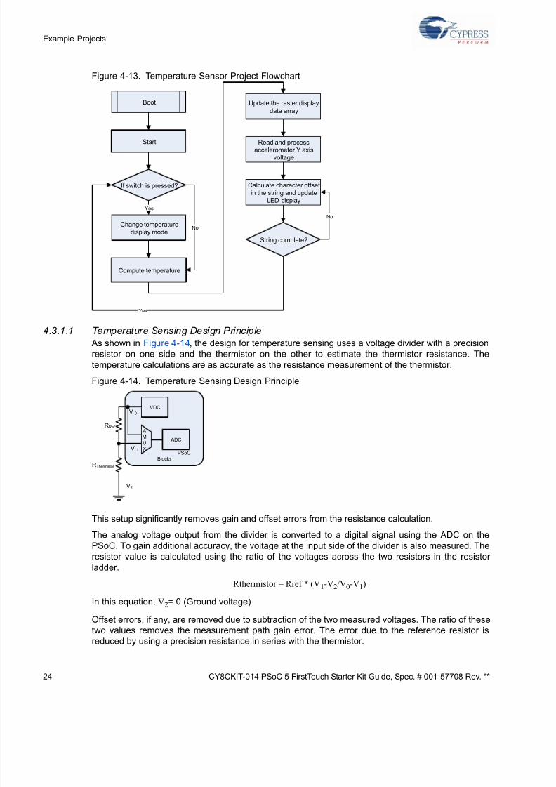
Figure 4-13. Temperature Sensor Project Flowchart
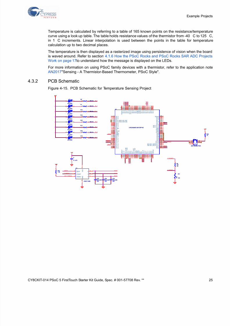
4.3.1.1 Temperature Sensing Design Principle
As shown in Figure 4-14, the design for temperature sensing uses a voltage divider with a precision
resistor on one side and the thermistor on the other to estimate the thermistor resistance. The
temperature calculations are as accurate as the resistance measurement of the thermistor.
Figure 4-14. Temperature Sensing Design Principle
This setup significantly removes gain and offset errors from the resistance calculation.
The analog voltage output from the divider is converted to a digital signal using the ADC on the
PSoC. To gain additional accuracy, the voltage at the input side of the divider is also measured. Theresistor value is calculated using the ratio of the voltages across the two resistors in the resistor
ladder.
Rthermistor = Rref * (V1-V2/V0-V1)
In this equation, V2 = 0 (Ground voltage)
Offset errors, if any, are removed due to subtraction of the two measured voltages. The ratio of these
two values removes the measurement path gain error. The error due to the reference resistor is
reduced by using a precision resistance in series with the thermistor.
Boot
Start
String complete?
Yes
Change temperature
display mode
Compute temperature
Update the raster display
data array
Read and processaccelerometer Y axis
voltage
Calculate character offset
in the string and update
LED display
If switch is pressed?
No
No
Yes
PSoC
Blocks
RRef
RThermistor
V2
V1
V0
A
M
U
X
ADC
VDC
Page 25
5/13/2018 CY8CKIT-014_PSoC 5 First Touch Starter Kit_Guide - slidepdf.com
http://slidepdf.com/reader/full/cy8ckit-014psoc-5-first-touch-starter-kitguide 25/44
CY8CKIT-014 PSoC 5 FirstTouch Starter Kit Guide, Spec. # 001-57708 Rev. ** 2
Example Projec
Temperature is calculated by referring to a table of 165 known points on the resistance/temperatu
curve using a look up table. The table holds resistance values of the thermistor from -40 C to 125 C
in 1 C increments. Linear interpolation is used between the points in the table for temperatu
calculation up to two decimal places.
The temperature is then displayed as a rasterized image using persistence of vision when the boar
is waved around. Refer to section 4.1.6 How the PSoC Rocks and PSoC Rocks SAR ADC ProjectWork on page 17 to understand how the message is displayed on the LEDs.
For more information on using PSoC family devices with a thermistor, refer to the application not
AN2017 "Sensing - A Thermistor-Based Thermometer, PSoC Style".
4.3.2 PCB Schematic
Figure 4-15. PCB Schematic for Temperature Sensing Project
P2_0
P4_3
P4_2
P4_1
P4_0
P2_3
P2_2
P2_1
ACC_ENABLE
P4_0
SWDCK
P 2_
1
X O U T
P 2_
3
ZOUTSWV
P4_1
P 4_
3
L O W B A T T
P 4_
2
SWDIO
S T / M O D E
M O D E
/XRES
P 2_
0
P 2_
2
YOUT
MODE
ACC_ENABLE
ST/MODE
ZOUT
YOUT
XOUTT_SENSE
T_POWER
T_
S E N S E
T_
P O W E R
3.3V
3.3V
3.3V
3.3V
0402
DNI
C29NOLOAD
0402
DNI
C29NOLOAD
FRAME
S1
SW PUSHBUTTON
FRAME
S1
SW PUSHBUTTON
1A2A
1B2B
3
0 4 0 2
R1768 ohm
0 4 0 2
R1768 ohm1 2
0603
D1
LED RED
0603
D1
LED RED
2 1
0402
C1
0.1 uFd0402
C1
0.1 uFd
0603
D5
LED RED
0603
D5
LED RED
2 1
0 4 0 2
R1868 ohm
0 4 0 2
R1868 ohm1 2
U1
KXSC7-2050
U1
KXSC7-2050
V D
D
1
MODE2
ST/MOT3
ENABLE4
X 5
Y6
Z7
G N D
8
0 6 0 3
R610K1%
0 6 0 3
R610K1%
0 4 0 2
R1968 ohm
0 4 0 2
R1968 ohm1 2
0402
DNI
C30NOLOAD
0402
DNI
C30NOLOAD
0603
D7
LED RED
0603
D7
LED RED
2 1
25
RT1
10K25
RT1
10K
0603
D2
LED RED
0603
D2
LED RED
2 1
U2
CY8C5588AXI-060 TQFP100
U2
CY8C5588AXI-060 TQFP100
P2_51
P2_62
P2_73
P12_4 I2C0_SCL, SIO4
P12_5 I2C0_SDA, SIO5
P6_46
P6_57
P6_68
P6_79
VSSb10
Ind11
Vboost12
Vbat13
VSSd14
XRES15
P5_016
P5_117
P5_218
P5_319
P1_020
P1_121
P1_222
P1_323
P1_424
P1_525
V D D i o 1
2 6
P 1_
6
2 7
P 1_
7
2 8
P 1 2_
6_
S I O
2 9
P 1 2_
7_
S I O
3 0
P 5_
4
3 1
P 5_
5
3 2
P 5_
6
3 3
P 5_
7
3 4
P 1 5_
6 D P
3 5
P 1 5_
7 D M
3 6
V D D d
3 7
V S S d
3 8
V C C d
3 9
N C 1
4 0
N C 2
4 1
P 1 5_
0
4 2
P 1 5_
1
4 3
P 3_
0
4 4
P 3_
1
4 5
P 3_
2
4 6
P 3_
3
4 7
P 3_
4
4 8
P 3_
5
4 9
V D D i o 3
5 0
VDDio075
P0_374
P0_273
P0_172
P0_071
P4_170
P4_069
SIO_P12_368
SIO_P12_267
VSSd66
VDDa65
VSSa64
VCCa63
NC862
NC761
NC660
NC559
NC458
NC357
P15_356
P15_255
SIO, I2C1_SDA P12_154
SIO, I2C1_SCL P12_053
P3_752
P3_651
P 2_
4
9 9
P 2_
3
9 8
P 2_
2
9 7
P 2_
1
9 6
P 2_
0
9 5
P
1 5_
5
9 4
P
1 5_
4
9 3
P 6_
3
9 2
P 6_
2
9 1
P 6_
1
9 0
P 6_
0
8 9
V D D d
8 8
V S S d
8 7
V C C d
8 6
P 4_
7
8 5
P 4_
6
8 4
P 4_
5
8 3
P 4_
4
8 2
P 4_
3
8 1
P 4_
2
8 0
P 0_
7
7 9
P 0_
6
7 8
P 0_
5
7 7
P 0_
4
7 6
V D D i o 2
1 0 0
0603
D4
LED RED
0603
D4
LED RED
2 1
0 4 0 2
R768 ohm
0 4 0 2
R768 ohm1 2
0603
D6
LED RED
0603
D6
LED RED
2 1
0402
DNI
C25NOLOAD
0402
DNI
C25NOLOAD
0 4 0 2
R1068 ohm
0 4 0 2
R1068 ohm1 2
0 4 0 2
R268 ohm
0 4 0 2
R268 ohm1 2
0 6 0 3
R201K
0 6 0 3
R201K
0 4 0 2
R1368 ohm
0 4 0 2
R1368 ohm1 2
0 4 0 2 R35
1.5K 0 4 0 2 R35
1.5K
1
2
0603
D8
LED RED
0603
D8
LED RED
2 1
0 4 0 2
R1668 ohm
0 4 0 2
R1668 ohm1 2
0603
D3
LED RED
0603
D3
LED RED
2 1
Page 26
5/13/2018 CY8CKIT-014_PSoC 5 First Touch Starter Kit_Guide - slidepdf.com
http://slidepdf.com/reader/full/cy8ckit-014psoc-5-first-touch-starter-kitguide 26/44
26 CY8CKIT-014 PSoC 5 FirstTouch Starter Kit Guide, Spec. # 001-57708 Rev. **
Example Projects
4.4 CapSense Slider
This project shows how to detect the position of a finger on the CapSense slider of the PSoC 5 First-
Touch Starter Kit board and indicate its position on the LED display.
Running the CapSense project:
1. Connect the PSoC 5 FirstTouch Starter Kit board to the USB port of the PC through the USBcable.
2. Click on the example project CapSenseSlider from Kits and Solutions present on the Startup
page of the PSoC Creator.
3. Make a folder in the desired location and click OK.
4. Project opens up in PSoC Creator and gets saved in that folder.
5. Follow step 1 to 4 in section 4.1.3 Build, Program, and Run the PSoC Rocks Project on page 14
to program the project into the PSoC 5 FirstTouch Starter Kit board.
6. When the download is complete, remove the PSoC 5 FirstTouch Starter Kit board from the USB
port and connect a 9V DC battery to the battery connector of the PSoC 5 FirstTouch Starter Kit
board.
7. Move your finger along the CapSense Slider and see the corresponding LEDs light up.
4.4.1 How the CapSense Slider Project Works
Capacitive sensing determines the presence of a conductive element, such as the finger, on a
capacitive sensor incorporated on the PCB. The kit consists of a bank of CapSense sensors in the
form of a slider. The size of the sensors and their position is designed such that when a finger is
placed on any part of the slider, at least three sensors are active (it detects the presence of the finger
by a change in its capacitance value).
The CapSense component provides APIs, which report the centroid (relative position) of the finger
on the slider based on the active sensors. The firmware then lights up the LED corresponding to this
centroid position.
Page 27
5/13/2018 CY8CKIT-014_PSoC 5 First Touch Starter Kit_Guide - slidepdf.com
http://slidepdf.com/reader/full/cy8ckit-014psoc-5-first-touch-starter-kitguide 27/44
CY8CKIT-014 PSoC 5 FirstTouch Starter Kit Guide, Spec. # 001-57708 Rev. ** 2
Example Projec
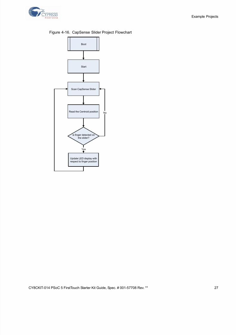
Figure 4-16. CapSense Slider Project Flowchart
Boot
Start
Scan CapSense Slider
Read the Centroid position
is finger detected on
the slider?
Update LED display with
respect to finger position
Yes
No
Page 28
5/13/2018 CY8CKIT-014_PSoC 5 First Touch Starter Kit_Guide - slidepdf.com
http://slidepdf.com/reader/full/cy8ckit-014psoc-5-first-touch-starter-kitguide 28/44
28 CY8CKIT-014 PSoC 5 FirstTouch Starter Kit Guide, Spec. # 001-57708 Rev. **
Example Projects
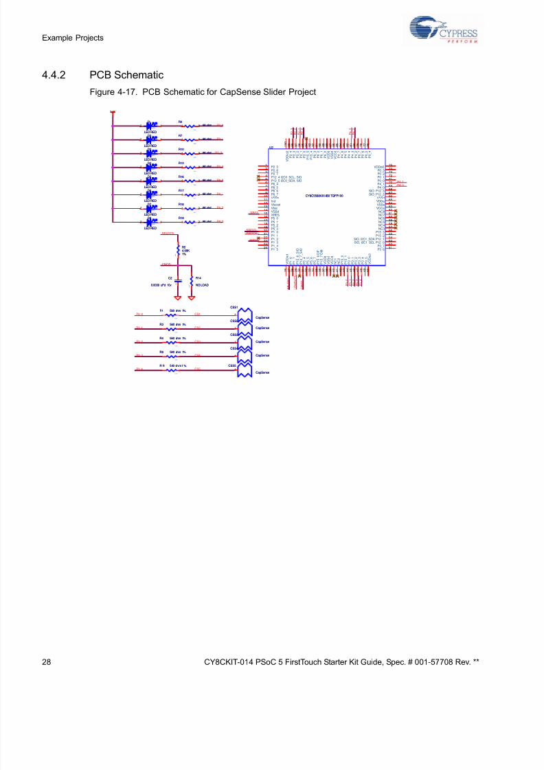
4.4.2 PCB Schematic
Figure 4-17. PCB Schematic for CapSense Slider Project
P2_0
P4_3
P4_2
P4_1
P4_0
P2_3
P2_2
P2_1
P4_0
SWDCK
P
2_
1
P
2_
3
SWV
P4_1
P
4_
3
L O W B A T T
P
4_
2
SWDIO
/XRES
P
2_
0
P
2_
2
RBLEED
CMOD
P3_0
P3_1
P3_2
P3_3
P3_4
CS1
CS2
CS3
CS4
CS5
P 3_
1
P 3_
2
P 3_
3
P 3_
4
P 3_
0
C M O D
R B L E E D
3.3V
0 6 0 3
R14
NO LOAD 0 6 0 3
R14
NO LOAD
CSS3
CapSense
CSS3
CapSense1
0603
D1
LED RED
0603
D1
LED RED
2 1
0 4 0 2
R1768 ohm
0 4 0 2
R1768 ohm1 2
0603
D5
LED RED
0603
D5
LED RED
2 1
0 4 0 2
R1868 ohm
0 4 0 2
R1868 ohm1 2
CSS2
CapSense
CSS2
CapSense1
0603
D7
LED RED
0603
D7
LED RED
2 1
0 4 0 2
R1968 ohm
0 4 0 2
R1968 ohm1 2
0603
D2
LED RED
0603
D2
LED RED
2 1
CSS1
CapSense
CSS1
CapSense1
CSS5
CapSense
CSS5
CapSense1
U2
CY8C5588AXI-060 TQFP100
U2
CY8C5588AXI-060 TQFP100
P2_51
P2_62
P2_73
P12_4 I2C0_SCL, SIO4
P12_5 I2C0_SDA, SIO5
P6_46
P6_57
P6_68
P6_79
VSSb10
Ind11
Vboost12
Vbat13
VSSd14
XRES15
P5_016
P5_117
P5_218
P5_319
P1_020
P1_121
P1_222
P1_323
P1_424
P1_525
V D D i o 1
2 6
P 1_
6
2 7
P 1_
7
2 8
P 1 2_
6_
S I O
2 9
P 1 2_
7_
S I O
3 0
P 5_
4
3 1
P 5_
5
3 2
P 5_
6
3 3
P 5_
7
3 4
P 1 5_
6 D P
3 5
P 1 5_
7 D M
3 6
V D D d
3 7
V S S d
3 8
V C C d
3 9
N C 1
4 0
N C 2
4 1
P 1 5_
0
4 2
P 1 5_
1
4 3
P 3_
0
4 4
P 3_
1
4 5
P 3_
2
4 6
P 3_
3
4 7
P 3_
4
4 8
P 3_
5
4 9
V D D i o 3
5 0
VDDio075
P0_374
P0_273
P0_172
P0_071
P4_170
P4_069
SIO_P12_368
SIO_P12_267
VSSd66
VDDa65
VSSa64
VCCa63
NC862
NC761
NC660
NC559
NC458
NC357
P15_356
P15_255
SIO, I2C1_SDA P12_154
SIO, I2C1_SCL P12_053
P3_752
P3_651
P 2_
4
9 9
P 2_
3
9 8
P 2_
2
9 7
P 2_
1
9 6
P 2_
0
9 5
P 1 5_
5
9 4
P 1 5_
4
9 3
P 6_
3
9 2
P 6_
2
9 1
P 6_
1
9 0
P 6_
0
8 9
V D D d
8 8
V S S d
8 7
V C C d
8 6
P 4_
7
8 5
P 4_
6
8 4
P 4_
5
8 3
P 4_
4
8 2
P 4_
3
8 1
P 4_
2
8 0
P 0_
7
7 9
P 0_
6
7 8
P 0_
5
7 7
P 0_
4
7 6
V D D i o 2
1 0 0
0603
D4
LED RED
0603
D4
LED RED
2 1
0 6 0 3
R 11 5 60 oh m 1 %
0 6 0 3
R 11 5 60 oh m 1 %
0 6 0 3
R1 560 ohm 1%
0 6 0 3
R1 560 ohm 1%
0 4 0 2
R768 ohm
0 4 0 2
R768 ohm1 2
0 6 0 3
R8 560 ohm 1%
0 6 0 3
R8 560 ohm 1%CSS4
CapSense
CSS4
CapSense1
0 4 0 2
R268 ohm
0 4 0 2
R268 ohm1 2
0 4 0 2
R1068 ohm
0 4 0 2
R1068 ohm1 2
0603
D6
LED RED
0603
D6
LED RED
2 1
0603
C2
0.0039 uFd 10v0603
C2
0.0039 uFd 10v
0 4 0 2
R1368 ohm
0 4 0 2
R1368 ohm1 2
0603
D8
LED RED
0603
D8
LED RED
2 1
0 6 0 3
R54.99K1%
0 6 0 3
R54.99K1%
0 6 0 3
R4 560 ohm 1%
0 6 0 3
R4 560 ohm 1%
0603
D3
LED RED
0603
D3
LED RED
2 1
0 4 0 2
R1668 ohm
0 4 0 2
R1668 ohm1 2
0 6 0 3
R3 560 ohm 1%
0 6 0 3
R3 560 ohm 1%
Page 29
5/13/2018 CY8CKIT-014_PSoC 5 First Touch Starter Kit_Guide - slidepdf.com
http://slidepdf.com/reader/full/cy8ckit-014psoc-5-first-touch-starter-kitguide 29/44
CY8CKIT-014 PSoC 5 FirstTouch Starter Kit Guide, Spec. # 001-57708 Rev. ** 2
Example Projec
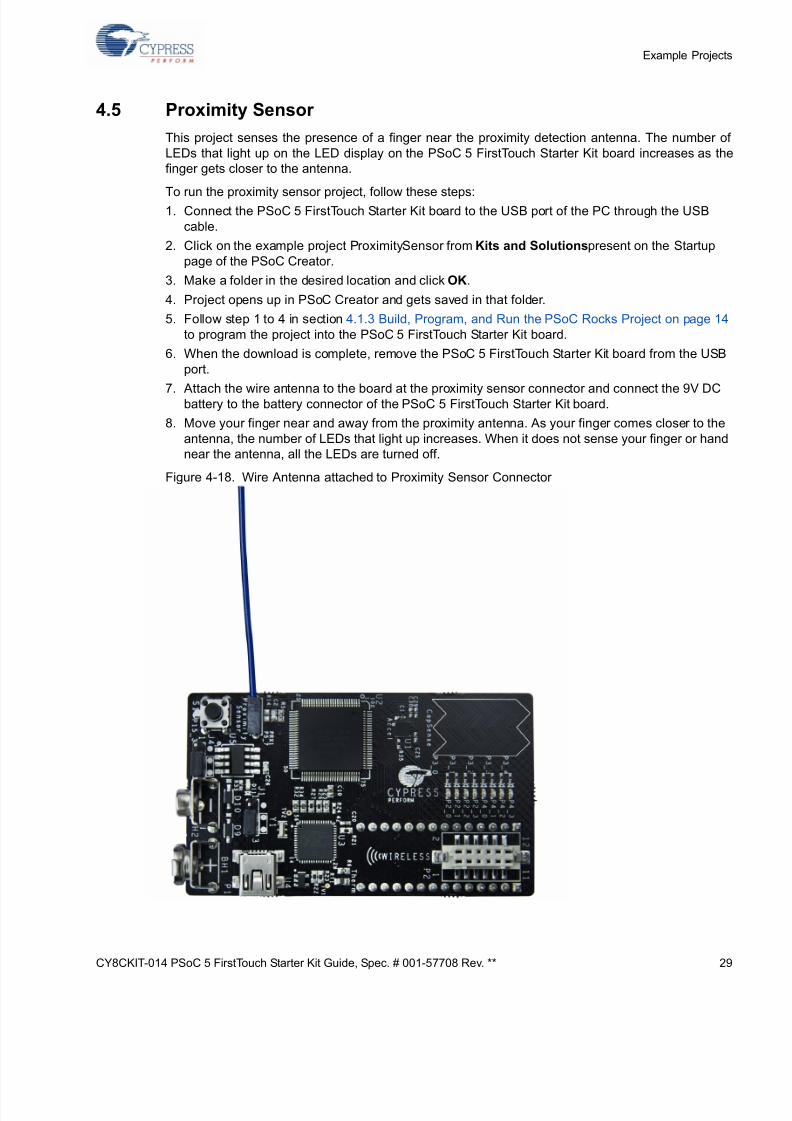
4.5 Proximity Sensor
This project senses the presence of a finger near the proximity detection antenna. The number o
LEDs that light up on the LED display on the PSoC 5 FirstTouch Starter Kit board increases as th
finger gets closer to the antenna.
To run the proximity sensor project, follow these steps:1. Connect the PSoC 5 FirstTouch Starter Kit board to the USB port of the PC through the USB
cable.
2. Click on the example project ProximitySensor from Kits and Solutions present on the Startup
page of the PSoC Creator.
3. Make a folder in the desired location and click OK.
4. Project opens up in PSoC Creator and gets saved in that folder.
5. Follow step 1 to 4 in section 4.1.3 Build, Program, and Run the PSoC Rocks Project on page 14
to program the project into the PSoC 5 FirstTouch Starter Kit board.
6. When the download is complete, remove the PSoC 5 FirstTouch Starter Kit board from the USB
port.
7. Attach the wire antenna to the board at the proximity sensor connector and connect the 9V DCbattery to the battery connector of the PSoC 5 FirstTouch Starter Kit board.
8. Move your finger near and away from the proximity antenna. As your finger comes closer to the
antenna, the number of LEDs that light up increases. When it does not sense your finger or hand
near the antenna, all the LEDs are turned off.
Figure 4-18. Wire Antenna attached to Proximity Sensor Connector
Page 30
5/13/2018 CY8CKIT-014_PSoC 5 First Touch Starter Kit_Guide - slidepdf.com
http://slidepdf.com/reader/full/cy8ckit-014psoc-5-first-touch-starter-kitguide 30/44
30 CY8CKIT-014 PSoC 5 FirstTouch Starter Kit Guide, Spec. # 001-57708 Rev. **
Example Projects
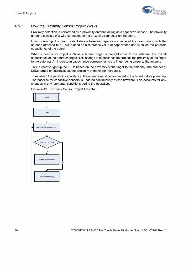
4.5.1 How the Proximity Sensor Project Works
Proximity detection is performed by a proximity antenna acting as a capacitive sensor. The proximity
antenna consists of a wire connected to the proximity connector on the board.
Upon power up, the board establishes a baseline capacitance value of the board along with the
antenna attached to it. This is used as a reference value of capacitance and is called the parasitic
capacitance of the board.
When a conductive object such as a human finger is brought close to the antenna, the overall
capacitance of the board changes. This change in capacitance determines the proximity of the finger
to the antenna. An increase in capacitance corresponds to the finger being closer to the antenna.
This is used to light up the LEDs based on the proximity of the finger to the antenna. The number of
LEDs turned on increases as the proximity of the finger increases.
To establish the parasitic capacitance, the antenna must be connected to the board before power up.
The baseline for capacitive sensors is updated continuously by the firmware. This accounts for any
changes in environmental conditions during the operation.
Figure 4-19. Proximity Sensor Project Flowchart
Boot
Start
Scan the Proximity sensor
Is sensor active?
Read signal value
Yes
No
update LED display
Page 31
5/13/2018 CY8CKIT-014_PSoC 5 First Touch Starter Kit_Guide - slidepdf.com
http://slidepdf.com/reader/full/cy8ckit-014psoc-5-first-touch-starter-kitguide 31/44
CY8CKIT-014 PSoC 5 FirstTouch Starter Kit Guide, Spec. # 001-57708 Rev. ** 3
Example Projec
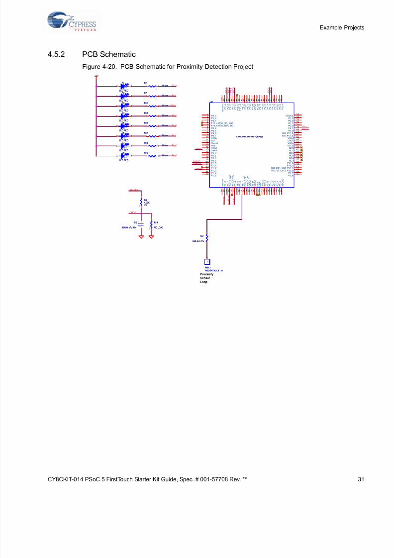
4.5.2 PCB Schematic
Figure 4-20. PCB Schematic for Proximity Detection Project
P2_0
P4_3
P4_2
P4_1
P4_0
P2_3
P2_2
P2_1
P4_0
SWDCK
P 2_
1
P 2_
3
SWV
P4_1
P 4_
3
L O W B A T T
P 4_
2
SWDIO
/XRES
P 2_
0
P 2_
2
RBLEED
CMOD
C M O D
R B L E E D
3.3V
ProximitySensorLoop
0 6 0 3
R14
NO LOAD 0 6 0 3
R14
NO LOAD
0 6
0 3 R31
560 ohm 1%
0 6
0 3 R31
560 ohm 1%
0603
D1
LED RED
0603
D1
LED RED
2 1
0 4 0 2
R1768 ohm
0 4 0 2
R1768 ohm1 2
PRX1
RECEPTACLE 1x1
PRX1
RECEPTACLE 1x1
1
1
0603
D5
LED RED
0603
D5
LED RED
2 1
0 4 0 2
R1868 ohm
0 4 0 2
R1868 ohm1 2
0603
D7
LED RED
0603
D7
LED RED
2 1
0 4 0 2
R1968 ohm
0 4 0 2
R1968 ohm1 2
0603
D2
LED RED
0603
D2
LED RED
2 1
U2
CY8C5588AXI-060 TQFP100
U2
CY8C5588AXI-060 TQFP100
P2_51
P2_62
P2_73
P12_4 I2C0_SCL, SIO4
P12_5 I2C0_SDA, SIO5
P6_46
P6_57
P6_68
P6_79
VSSb10
Ind11
Vboost12
Vbat13
VSSd14
XRES15
P5_016
P5_117
P5_218
P5_319
P1_020
P1_121
P1_222
P1_323
P1_424
P1_525
V D D i o 1
2 6
P 1_
6
2 7
P 1_
7
2 8
P 1 2_
6_
S I O
2 9
P 1 2_
7_
S I O
3 0
P 5_
4
3 1
P 5_
5
3 2
P 5_
6
3 3
P 5_
7
3 4
P 1 5_
6 D P
3 5
P 1 5_
7 D M
3 6
V D D d
3 7
V S S d
3 8
V C C d
3 9
N C 1
4 0
N C 2
4 1
P 1 5_
0
4 2
P 1 5_
1
4 3
P 3_
0
4 4
P 3_
1
4 5
P 3_
2
4 6
P 3_
3
4 7
P 3_
4
4 8
P 3_
5
4 9
V D D i o 3
5 0
VDDio075
P0_374
P0_273
P0_172
P0_071
P4_170
P4_069
SIO_P12_368
SIO_P12_267
VSSd66
VDDa65
VSSa64
VCCa63
NC862
NC761
NC660
NC559
NC458
NC357
P15_356
P15_255
SIO, I2C1_SDA P12_154
SIO, I2C1_SCL P12_053
P3_752
P3_651
P 2_
4
9 9
P 2_
3
9 8
P 2_
2
9 7
P 2_
1
9 6
P 2_
0
9 5
P 1 5_
5
9 4
P 1 5_
4
9 3
P 6_
3
9 2
P 6_
2
9 1
P 6_
1
9 0
P 6_
0
8 9
V D D d
8 8
V S S d
8 7
V C C d
8 6
P 4_
7
8 5
P 4_
6
8 4
P 4_
5
8 3
P 4_
4
8 2
P 4_
3
8 1
P 4_
2
8 0
P 0_
7
7 9
P 0_
6
7 8
P 0_
5
7 7
P 0_
4
7 6
V D D i o 2
1 0 0
0603
D4
LED RED
0603
D4
LED RED
2 1
0 4 0 2
R768 ohm
0 4 0 2
R768 ohm1 2
0 4 0 2
R268 ohm
0 4 0 2
R268 ohm1 2
0 4 0 2
R1068 ohm
0 4 0 2
R1068 ohm1 2
0603
D6
LED RED
0603
D6
LED RED
2 1
0603
C2
0.0039 uFd 10v0603
C2
0.0039 uFd 10v
0 4 0 2
R1368 ohm
0 4 0 2
R1368 ohm1 2
0603
D8
LED RED
0603
D8
LED RED
2 1
0 6 0 3
R54.99K1%
0 6 0 3
R54.99K1%
0603
D3
LED RED
0603
D3
LED RED
2 1
0 4 0 2
R1668 ohm
0 4 0 2
R1668 ohm1 2
Page 32
5/13/2018 CY8CKIT-014_PSoC 5 First Touch Starter Kit_Guide - slidepdf.com
http://slidepdf.com/reader/full/cy8ckit-014psoc-5-first-touch-starter-kitguide 32/44
32 CY8CKIT-014 PSoC 5 FirstTouch Starter Kit Guide, Spec. # 001-57708 Rev. **
Example Projects
Page 33
5/13/2018 CY8CKIT-014_PSoC 5 First Touch Starter Kit_Guide - slidepdf.com
http://slidepdf.com/reader/full/cy8ckit-014psoc-5-first-touch-starter-kitguide 33/44
CY8CKIT-014 PSoC 5 FirstTouch Starter Kit Guide, Spec. # 001-57708 Rev. ** 3
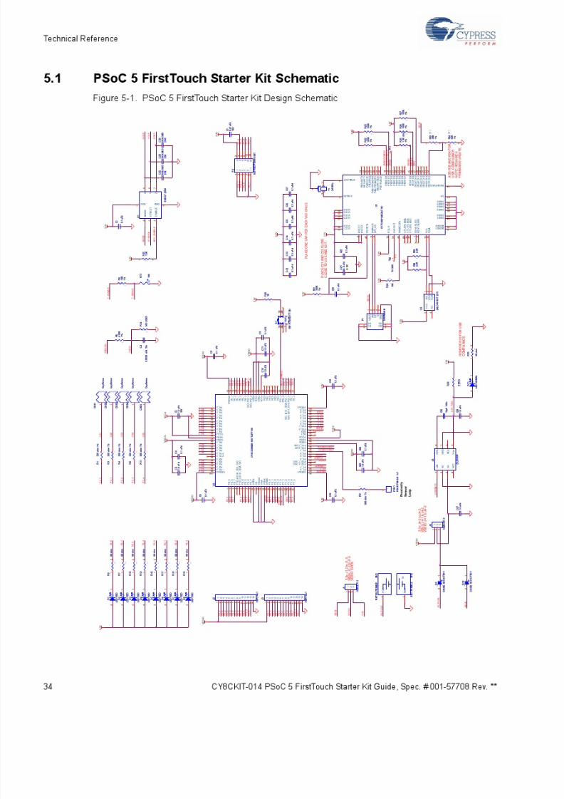
5. Technical Reference
When creating a new project or modifying an existing project, refer to the PSoC 5 FirstTouch Start
Kit board schematic provided in section 5.1 PSoC 5 FirstTouch Starter Kit Schematic on page 34 an
the pin assignment tables listed in section 5.2 PSoC 5 Pin Assignment on PSoC 5 FirstTouch Starte
Kit Board on page 41.
Page 34
5/13/2018 CY8CKIT-014_PSoC 5 First Touch Starter Kit_Guide - slidepdf.com
http://slidepdf.com/reader/full/cy8ckit-014psoc-5-first-touch-starter-kitguide 34/44
Page 35
5/13/2018 CY8CKIT-014_PSoC 5 First Touch Starter Kit_Guide - slidepdf.com
http://slidepdf.com/reader/full/cy8ckit-014psoc-5-first-touch-starter-kitguide 35/44
CY8CKIT-014 PSoC 5 FirstTouch Starter Kit Guide, Spec. # 001-57708 Rev. ** 3
Technical Referenc
5.1.1 Hardware Jumpers
There are two jumpers on the PCB for setting the power configuration. They are J1 and J4. Thes
jumpers are for selecting the source for powering the PSoC 5. The options are to power the PSoC
from the on board 3.3V regulator, to run the PSoC 5 from the USB connector, or to supply powe
from off board using the J2/J3 connectors.
J4 is for selecting the power source to drive the 3.3 volt regulator. This regulator can be used t
power everything on the board or just the accelerometer. The regulator cannot be powered indepen
dently from the VDDIO bus. It must either power the VDDIO bus or be powered by it.
J1 is for selecting the power source of the PSoC 5. The I/O cells of the PSoC 5 are driven by thi
source level. Only the I/O cells that the accelerometer is connected to remain connected to 3.3V an
must power up with the VDDIO bus or after the VDDIO power bus.
Valid combinations of the jumpers are:
■ 3.3V operation
❐ J1-2 to J1-3
❐ J4-2 to J4-3
■ VBUS operation❐ J1-1 to J1-2
❐ J4-1 to J4-2
■ VDDIO
❐ J1 open
❐ J4-1 to J4-2
Page 36
5/13/2018 CY8CKIT-014_PSoC 5 First Touch Starter Kit_Guide - slidepdf.com
http://slidepdf.com/reader/full/cy8ckit-014psoc-5-first-touch-starter-kitguide 36/44
36 CY8CKIT-014 PSoC 5 FirstTouch Starter Kit Guide, Spec. # 001-57708 Rev. **
Technical Reference
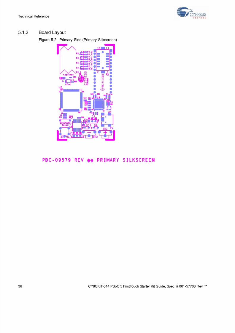
5.1.2 Board Layout
Figure 5-2. Primary Side (Primary Silkscreen)
Page 37
5/13/2018 CY8CKIT-014_PSoC 5 First Touch Starter Kit_Guide - slidepdf.com
http://slidepdf.com/reader/full/cy8ckit-014psoc-5-first-touch-starter-kitguide 37/44
CY8CKIT-014 PSoC 5 FirstTouch Starter Kit Guide, Spec. # 001-57708 Rev. ** 3
Technical Referenc
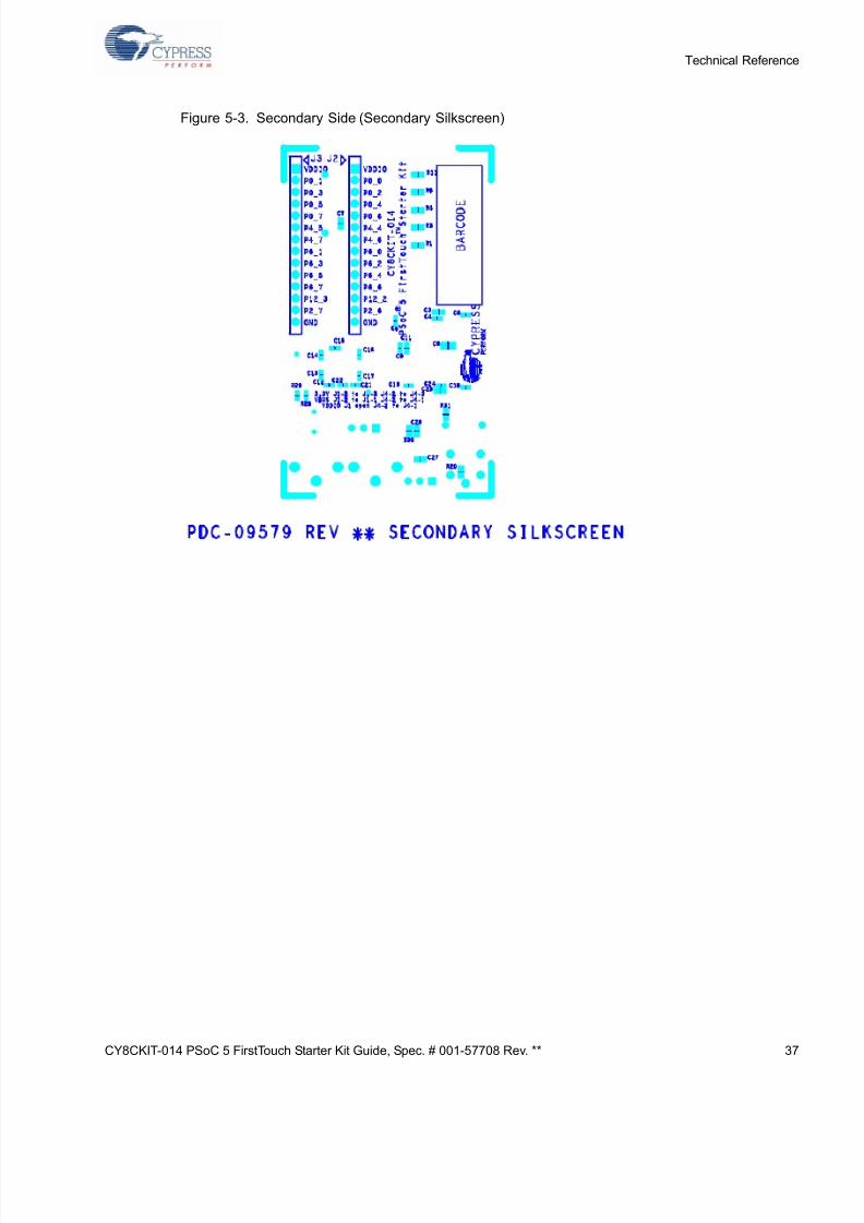
Figure 5-3. Secondary Side (Secondary Silkscreen)
Page 38
5/13/2018 CY8CKIT-014_PSoC 5 First Touch Starter Kit_Guide - slidepdf.com
http://slidepdf.com/reader/full/cy8ckit-014psoc-5-first-touch-starter-kitguide 38/44
38 CY8CKIT-014 PSoC 5 FirstTouch Starter Kit Guide, Spec. # 001-57708 Rev. **
Technical Reference
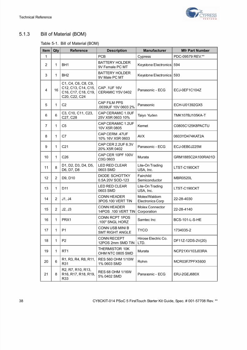
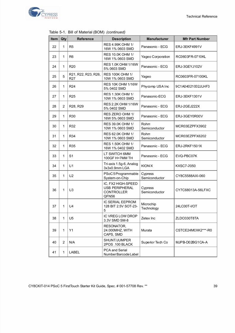
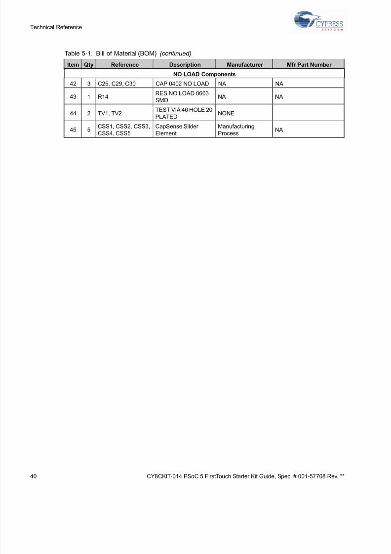
5.1.3 Bill of Material (BOM)
Table 5-1. Bill of Material (BOM)
Item Qty Reference Description Manufacturer Mfr Part Number
1 PCB Cypress PDC-09579 REV.**
2 1 BH1BATTERY HOLDER
9V Female PC MTKeystone Electronics 594
3 1 BH2BATTERY HOLDER
9V Male PC MTKeystone Electronics 593
4 16
C1, C4, C6, C8, C9,
C12, C13, C14, C15,
C16, C17, C18, C19,
C20, C22, C24
CAP .1UF 16V
CERAMIC Y5V 0402Panasonic - ECG ECJ-0EF1C104Z
5 1 C2CAP FILM PPS
.0039UF 10V 0603 2%Panasonic ECH-U01392GX5
6 6C3, C10, C11, C23,
C27, C28
CAP CERAMIC 1.0UF
25V X5R 0603 10%Taiyo Yuden TMK107BJ105KA-T
7 1 C5CAP CERAMIC 1.2UF
10V X5R 0805Kemet C0805C125K8PACTU
8 1 C7CAP CERM .47UF
10% 16V X5R 0603AVX 0603YD474KAT2A
9 1 C21CAP CER 2.2UF 6.3V
20% X5R 0402Panasonic - ECG ECJ-0EB0J225M
10 1 C26CAP CER 10PF 100V
C0G 0603Murata GRM1885C2A100RA01D
11 8D1, D2, D3, D4, D5,
D6, D7, D8
LED RED CLEAR
0603 SMD
Lite-On Trading
USA, Inc.LTST-C190CKT
12 2 D9, D10DIODE SCHOTTKY
0.5A 20V SOD-123
Fairchild
Semiconductor MBR0520L
13 1 D11LED RED CLEAR
0603 SMD
Lite-On Trading
USA, Inc.LTST-C190CKT
14 2 J1, J4CONN HEADER
3POS.100 VERT TIN
Molex/Waldom
Electronics Corp22-28-4030
15 2 J2, J3CONN HEADER
14POS .100 VERT TIN
Molex Connector
Corporation22-28-4140
16 1 PRX1CONN RCPT 1POS
.100" SNGL HORZSamtec Inc BCS-101-L-S-HE
17 1 P1CONN USB MINI B
SMT RIGHT ANGLETYCO 1734035-2
18 1 P2CONN RECEPT
12POS 2mm SMD TIN
Hirose Electric Co.
LTD.
DF11Z-12DS-2V(20)
19 1 RT1THERMISTOR 10K
OHM NTC 0805 SMDMurata NCP21XV103J03RA
20 6R1, R3, R4, R8, R11,
R31
RES 560 OHM 1/10W
1% 0603 SMDRohm MCR03EZPFX5600
21 8
R2, R7, R10, R13,
R16, R17, R18, R19,
R33
RES 68 OHM 1/16W
5% 0402 SMDPanasonic - ECG ERJ-2GEJ680X
Page 39
5/13/2018 CY8CKIT-014_PSoC 5 First Touch Starter Kit_Guide - slidepdf.com
http://slidepdf.com/reader/full/cy8ckit-014psoc-5-first-touch-starter-kitguide 39/44
CY8CKIT-014 PSoC 5 FirstTouch Starter Kit Guide, Spec. # 001-57708 Rev. ** 3
Technical Referenc
22 1 R5RES 4.99K OHM 1/
16W 1% 0603 SMDPanasonic - ECG ERJ-3EKF4991V
23 1 R6
RES 10.0K OHM 1/
16W 1% 0603 SMD Yageo Corporation RC0603FR-0710KL
24 1 R20RES 1.0K OHM 1/16W
5% 0603 SMDPanasonic - ECG ERJ-3GEYJ102V
25 5R21, R22, R23, R26,
R27
RES 100K OHM 1/
10W 1% 0603 SMDYageo RC0603FR-07100KL
26 1 R24RES 10K OHM 1/16W
5% 0402 SMDPhycomp USA Inc 9C1A04021002JLHF3
27 1 R25RES 1.30K OHM 1/
10W 1% 0603 SMDPanasonic-ECG ERJ-3EKF1301V
28 2 R28, R29RES 2.2K OHM 1/16W
5% 0402 SMDPanasonic - ECG ERJ-2GEJ222X
29 1 R30RES ZERO OHM 1/
16W 5% 0603 SMD Panasonic - ECG ERJ-3GEY0R00V
30 1 R32RES 39.0K OHM 1/
10W 1% 0603 SMD
Rohm
Semiconductor MCR03EZPFX3902
31 1 R34RES 62.0K OHM 1/
10W 1% 0603 SMD
Rohm
Semiconductor MCR03EZPFX6202
32 1 R35RES 1.50K OHM 1/
16W 1% 0402 SMDPanasonic - ECG ERJ-2RKF1501X
33 1 S1LT SWITCH 6MM
100GF H=7MM THPanasonic - ECG EVQ-PBC07K
34 1 U1Tri-axis 1.5g-6, Analog
3x3x0.9mm LGAKIONIX KXSC7-2050
35 1 U2 PSoC 5 ProgrammableSystem-on-Chip
CypressSemiconductor
CY8C5588AXI-060
36 1 U3
IC, FX2 HIGH-SPEED
USB PERIPHERAL
CONTROLLER
QFN56
Cypress
Semiconductor CY7C68013A-56LFXC
37 1 U4
IC SERIAL EEPROM
128 BIT 2.5V SOT-23-
5
Microchip
Technology24LC00T-I/OT
38 1 U5IC VREG LOW DROP
3.3V SMD SM-8Zetex Inc ZLDO330T8TA
39 1 Y1
RESONATOR,
24.000MHZ, WITH
CAPS, SMD
Murata CSTCE24M0XK2***-R0
40 2 N/ASHUNT/JUMPER
2POS .100 BLACKSuperior Tech Co MJPB-D02BG1CA-A
41 1 LABELPCA and Serial
Number Barcode Label
Table 5-1. Bill of Material (BOM) (continued)
Item Qty Reference Description Manufacturer Mfr Part Number
Page 40
5/13/2018 CY8CKIT-014_PSoC 5 First Touch Starter Kit_Guide - slidepdf.com
http://slidepdf.com/reader/full/cy8ckit-014psoc-5-first-touch-starter-kitguide 40/44
40 CY8CKIT-014 PSoC 5 FirstTouch Starter Kit Guide, Spec. # 001-57708 Rev. **
Technical Reference
NO LOAD Components
42 3 C25, C29, C30 CAP 0402 NO LOAD NA NA
43 1 R14RES NO LOAD 0603
SMD NA NA
44 2 TV1, TV2TEST VIA 40 HOLE 20
PLATEDNONE
45 5CSS1, CSS2, CSS3,
CSS4, CSS5
CapSense Slider
Element
Manufacturing
ProcessNA
Table 5-1. Bill of Material (BOM) (continued)
Item Qty Reference Description Manufacturer Mfr Part Number
Page 41
5/13/2018 CY8CKIT-014_PSoC 5 First Touch Starter Kit_Guide - slidepdf.com
http://slidepdf.com/reader/full/cy8ckit-014psoc-5-first-touch-starter-kitguide 41/44
CY8CKIT-014 PSoC 5 FirstTouch Starter Kit Guide, Spec. # 001-57708 Rev. ** 4
Technical Referenc
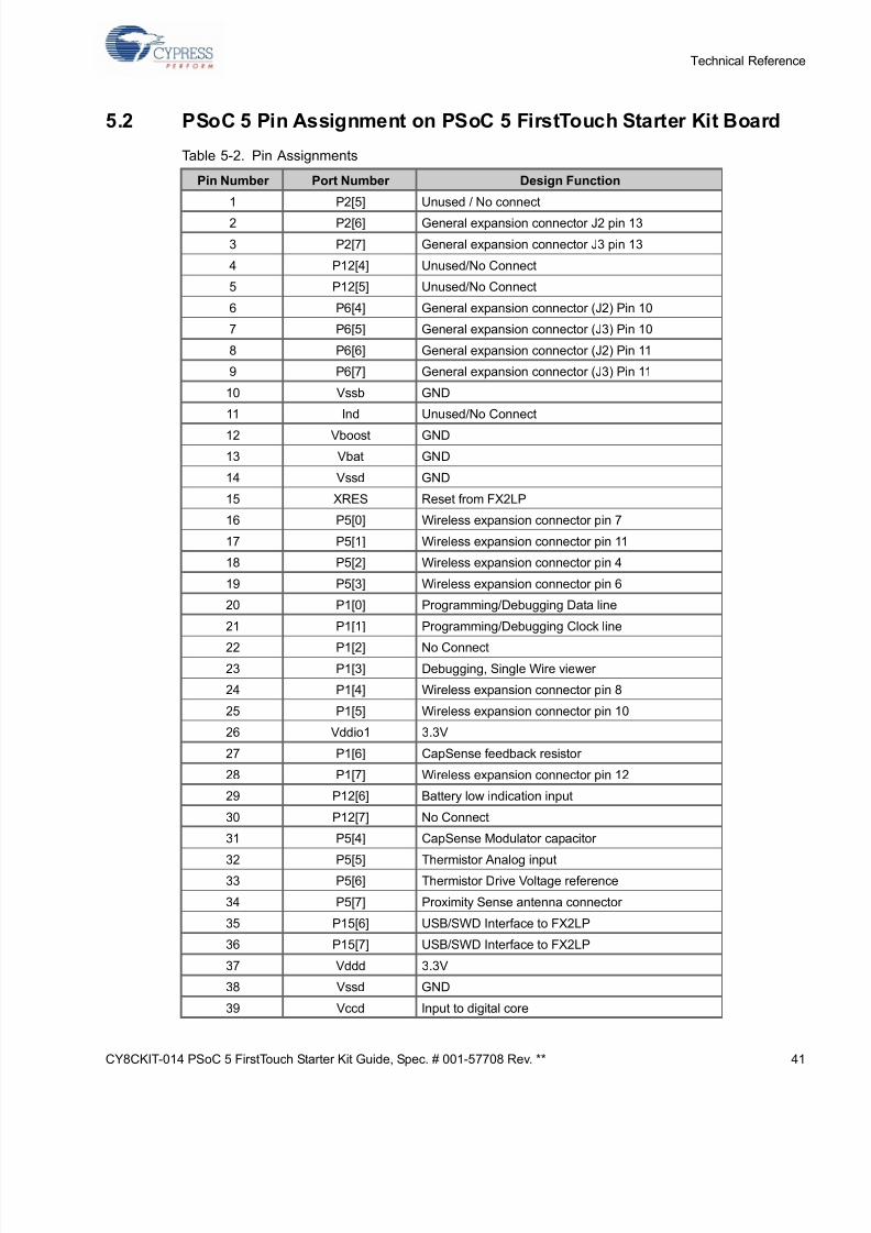
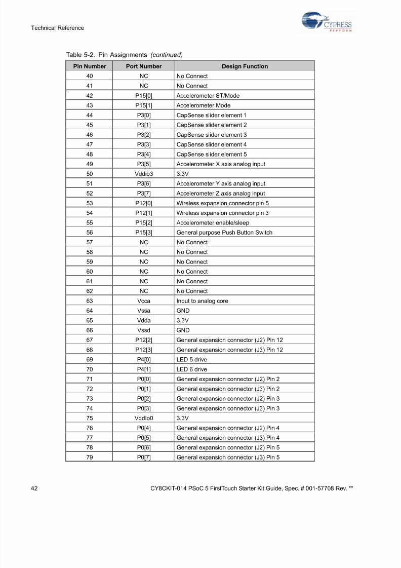
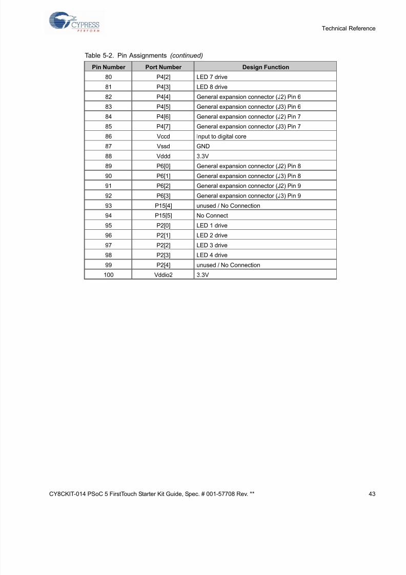
5.2 PSoC 5 Pin Assignment on PSoC 5 FirstTouch Starter Kit Board
Table 5-2. Pin Assignments
Pin Number Port Number Design Function
1 P2[5] Unused / No connect
2 P2[6] General expansion connector J2 pin 13
3 P2[7] General expansion connector J3 pin 13
4 P12[4] Unused/No Connect
5 P12[5] Unused/No Connect
6 P6[4] General expansion connector (J2) Pin 10
7 P6[5] General expansion connector (J3) Pin 10
8 P6[6] General expansion connector (J2) Pin 11
9 P6[7] General expansion connector (J3) Pin 11
10 Vssb GND
11 Ind Unused/No Connect
12 Vboost GND
13 Vbat GND
14 Vssd GND
15 XRES Reset from FX2LP
16 P5[0] Wireless expansion connector pin 7
17 P5[1] Wireless expansion connector pin 11
18 P5[2] Wireless expansion connector pin 4
19 P5[3] Wireless expansion connector pin 6
20 P1[0] Programming/Debugging Data line
21 P1[1] Programming/Debugging Clock line
22 P1[2] No Connect
23 P1[3] Debugging, Single Wire viewer
24 P1[4] Wireless expansion connector pin 8
25 P1[5] Wireless expansion connector pin 10
26 Vddio1 3.3V
27 P1[6] CapSense feedback resistor
28 P1[7] Wireless expansion connector pin 12
29 P12[6] Battery low indication input
30 P12[7] No Connect
31 P5[4] CapSense Modulator capacitor
32 P5[5] Thermistor Analog input33 P5[6] Thermistor Drive Voltage reference
34 P5[7] Proximity Sense antenna connector
35 P15[6] USB/SWD Interface to FX2LP
36 P15[7] USB/SWD Interface to FX2LP
37 Vddd 3.3V
38 Vssd GND
39 Vccd Input to digital core
Page 42
5/13/2018 CY8CKIT-014_PSoC 5 First Touch Starter Kit_Guide - slidepdf.com
http://slidepdf.com/reader/full/cy8ckit-014psoc-5-first-touch-starter-kitguide 42/44
42 CY8CKIT-014 PSoC 5 FirstTouch Starter Kit Guide, Spec. # 001-57708 Rev. **
Technical Reference
40 NC No Connect
41 NC No Connect
42 P15[0] Accelerometer ST/Mode
43 P15[1] Accelerometer Mode
44 P3[0] CapSense slider element 1
45 P3[1] CapSense slider element 2
46 P3[2] CapSense slider element 3
47 P3[3] CapSense slider element 4
48 P3[4] CapSense slider element 5
49 P3[5] Accelerometer X axis analog input
50 Vddio3 3.3V
51 P3[6] Accelerometer Y axis analog input
52 P3[7] Accelerometer Z axis analog input
53 P12[0] Wireless expansion connector pin 5
54 P12[1] Wireless expansion connector pin 3
55 P15[2] Accelerometer enable/sleep
56 P15[3] General purpose Push Button Switch
57 NC No Connect
58 NC No Connect
59 NC No Connect
60 NC No Connect
61 NC No Connect
62 NC No Connect
63 Vcca Input to analog core
64 Vssa GND
65 Vdda 3.3V
66 Vssd GND
67 P12[2] General expansion connector (J2) Pin 12
68 P12[3] General expansion connector (J3) Pin 12
69 P4[0] LED 5 drive
70 P4[1] LED 6 drive
71 P0[0] General expansion connector (J2) Pin 2
72 P0[1] General expansion connector (J3) Pin 2
73 P0[2] General expansion connector (J2) Pin 3
74 P0[3] General expansion connector (J3) Pin 3
75 VddIo0 3.3V
76 P0[4] General expansion connector (J2) Pin 4
77 P0[5] General expansion connector (J3) Pin 4
78 P0[6] General expansion connector (J2) Pin 5
79 P0[7] General expansion connector (J3) Pin 5
Table 5-2. Pin Assignments (continued)
Pin Number Port Number Design Function
Page 43
5/13/2018 CY8CKIT-014_PSoC 5 First Touch Starter Kit_Guide - slidepdf.com
http://slidepdf.com/reader/full/cy8ckit-014psoc-5-first-touch-starter-kitguide 43/44
CY8CKIT-014 PSoC 5 FirstTouch Starter Kit Guide, Spec. # 001-57708 Rev. ** 4
Technical Referenc
80 P4[2] LED 7 drive
81 P4[3] LED 8 drive
82 P4[4] General expansion connector (J2) Pin 6
83 P4[5] General expansion connector (J3) Pin 6
84 P4[6] General expansion connector (J2) Pin 7
85 P4[7] General expansion connector (J3) Pin 7
86 Vccd Input to digital core
87 Vssd GND
88 Vddd 3.3V
89 P6[0] General expansion connector (J2) Pin 8
90 P6[1] General expansion connector (J3) Pin 8
91 P6[2] General expansion connector (J2) Pin 9
92 P6[3] General expansion connector (J3) Pin 9
93 P15[4] unused / No Connection
94 P15[5] No Connect
95 P2[0] LED 1 drive
96 P2[1] LED 2 drive
97 P2[2] LED 3 drive
98 P2[3] LED 4 drive
99 P2[4] unused / No Connection
100 Vddio2 3.3V
Table 5-2. Pin Assignments (continued)
Pin Number Port Number Design Function
Page 44
5/13/2018 CY8CKIT-014_PSoC 5 First Touch Starter Kit_Guide - slidepdf.com
http://slidepdf.com/reader/full/cy8ckit-014psoc-5-first-touch-starter-kitguide 44/44
44 CY8CKIT-014 PSoC 5 FirstTouch Starter Kit Guide, Spec. # 001-57708 Rev. **
Technical Reference