Technische Berichte Nr. 64 des Hasso-Plattner-Instituts für Softwaresystemtechnik an der Universität Potsdam Cyber-Physical Systems with Dynamic Structure: Towards Modeling and Verification of Inductive Invariants Basil Becker, Holger Giese
Transcript
Technische Berichte Nr. 64
des Hasso-Plattner-Instituts für Softwaresystemtechnik an der Universität Potsdam
Cyber-Physical Systems
with Dynamic Structure:
Towards Modeling and
Verification of Inductive
Invariants
Basil Becker, Holger Giese
Technische Berichte des Hasso-Plattner-Instituts für Softwaresystemtechnik an der Universität Potsdam
Technische Berichte des Hasso-Plattner-Instituts für Softwaresystemtechnik an der Universität Potsdam | 64
Basil Becker | Holger Giese
Cyber-Physical Systems with Dynamic Structure
Towards Modeling and Verification of Inductive Invariants
Universitätsverlag Potsdam
Bibliografische Information der Deutschen Nationalbibliothek Die Deutsche Nationalbibliothek verzeichnet diese Publikation in der Deutschen Nationalbibliografie; detaillierte bibliografische Daten sind im Internet über http://dnb.de/ abrufbar. Universitätsverlag Potsdam 2012 http://verlag.ub.uni-potsdam.de/ Am Neuen Palais 10, 14469 Potsdam Tel.: +49 (0)331 977 2533 / Fax: 2292 E-Mail: [email protected] Die Schriftenreihe Technische Berichte des Hasso-Plattner-Instituts für Softwaresystemtechnik an der Universität Potsdam wird herausgegeben von den Professoren des Hasso-Plattner-Instituts für Softwaresystemtechnik an der Universität Potsdam. ISSN (print) 1613-5652 ISSN (online) 2191-1665 Das Manuskript ist urheberrechtlich geschützt. Online veröffentlicht auf dem Publikationsserver der Universität Potsdam URL http://pub.ub.uni-potsdam.de/volltexte/2012/6243/ URN urn:nbn:de:kobv:517-opus-62437 http://nbn-resolving.de/urn:nbn:de:kobv:517-opus-62437 Zugleich gedruckt erschienen im Universitätsverlag Potsdam: ISBN 978-3-86956-217-9
Cyber-physical systems achieve sophisticated system behavior exploring thetight interconnection of physical coupling present in classical engineering sys-tems and information technology based coupling. A particular challengingcase are systems where these cyber-physical systems are formed ad hoc ac-cording to the specific local topology, the available networking capabilities, andthe goals and constraints of the subsystems captured by the information pro-cessing part.
In this paper we present a formalism that permits to model the sketched classof cyber-physical systems. The ad hoc formation of tightly coupled subsys-tems of arbitrary size are specified using a UML-based graph transformationsystem approach. Differential equations are employed to define the resultingtightly coupled behavior. Together, both form hybrid graph transformation sys-tems where the graph transformation rules define the discrete steps wherethe topology or modes may change, while the differential equations capturethe continuous behavior in between such discrete changes. In addition, wedemonstrate that automated analysis techniques known for timed graph trans-formation systems for inductive invariants can be extended to also cover thehybrid case for an expressive case of hybrid models where the formed tightlycoupled subsystems are restricted to smaller local networks.
Cyber-physical systems (CPS) [10] exhibit sophisticated system behavior thatresults from the tight interconnection of physical coupling present in classicalengineering systems and coupling via information technology that cannot beachieved by classical control or information technology alone.
A particular challenging case are systems where these cyber-physical sys-tems are formed ad hoc according to the specific local topology, the availablenetworking capabilities, and the goals and constraints of the subsystems cap-tured by the information processing part.
In such cyber-physical systems with dynamic structure we have to cover twosources for complexity: At first we have cyber-physical subsystems tightly cou-pled locally via physical effects but also information technology. In addition, atthe coarse-grain level we have arbitrary complex topologies that evolve overtime and control which locally tightly coupled cyber-physical subsystems comeinto existence.
While the locally tightly coupled cyber-physical subsystems alone already re-sult in complex hybrid systems [1] with finite discrete state space, the coarse-grain level results also in dynamic structures that evolve potentially infinitelyand where the relevant initial configurations can be only characterized by someconstraints but not collapsed into a finite set of initial configurations. Therefore,we in essence have to deal with hybrid systems that also have a infinite dis-crete state component.
1
2 Introduction
1.1 Contribution
In this paper we present a formalism that permits to model the sketched classof cyber-physical systems. The ad hoc formation of tightly coupled cyber-physical subsystems of arbitrary size is specified using UML-based graphtransformation systems. Modes, rules for mode changes, and differential equa-tions defined for the modes are employed to define the tightly coupled cyber-physical behavior by means of hybrid behavior. Together, both options resultin hybrid graph transformation systems where the graph transformation rulesdefine the discrete steps such as formation of subsystems or mode changes,while the differential equations of the modes capture the continuous behaviorin between such discrete changes.
Besides modeling the outlined class of cyber-physical systems, we of coursealso need means to predict their behavior and provide guarantees for crucialsystem properties. To this means, we demonstrate that automated analysistechniques for inductive invariants known for untimed and timed graph transfor-mation systems can be extended to also cover the hybrid case for a subclassof the presented approach, where the tightly coupled cyber-physical subsys-tems result from only local reconfiguration rules and are of bounded size.
1.2 Former Work
The presented results extend former work that started with an approach tomodel and checking inductive invariants for graph transformation systems in[6]. This work was combined with result for the checking of timed coordina-tion behavior in [13]. However, the structural rules and the real-time aspectshad to provide the required guarantees independent of each other. Later, in[7] the modeling and checking concepts have been extended to timed graphtransformation systems where real-time constraints for the ad hoc formationof coordination structures could be first modeled and also verified. In contrastto these earlier results, in the current paper the supported hybrid graph trans-formation systems permit that the complex hybrid behavior that results fromthe tight coupling via physical effects as well as information technology can becaptured. In addition, also the checking procedures have been extended to asubclass of these hybrid systems.
Application Example 3
1.3 Application Example
In this paper we will use the RailCab1 system as running example to illustratethe presented approach. The RailCab system has been developed at the Uni-versity of Paderborn and targets the development of a new railway technology(see Figure 1.1).
Figure 1.1: The test track and shuttle prototype of the RailCab project
The RailCab system’s main constituents are so called Shuttles, which are smalland autonomous vehicles and can either be used for cargo or persons. Cus-tomers place their transportation requests online and shuttle can reply to theserequests by an offer. However, to be a competitive alternative to establishedpublic and individual transportation, the shuttles have to be fast and affordable.This can only be achieved if the shuttles consume less or at least not more en-ergy per passenger than other means of transport. Unfortunately the energyconsumption of a single shuttle, driving alone, is worse than that of classi-cal trains. But it can be improved if multiple shuttles collaborate and build aconvoy. Within the convoy only the first shuttle has to overcome the wind resis-tance and all following shuttles can benefit from the first shuttle’s work. Thusin average the energy consumption of multiple shuttles is less compared totoday’s most energy efficient trains.
The convoy are not build by mechanical coupling but via information technol-ogy and thus a convoy is a nice example for a cyber-physical system where
1http://www.railcab.de
4 Introduction
besides the physical coupling effects also information technology plays a majorrole. In addition, the RailCab system requires that the convoys are establishedbut also destructed according to the local situation and thus we have a cyber-physical system with dynamic structures.
Obviously the RailCab system is a safety critical system. As the shuttles areautonomous, the system’s safety has to be guaranteed for this cyber-physicalsystem with dynamic structures. In this paper we focus on the convoy buildingaspects of the RailCab system, demonstrate how it can be modeled with thepresented approach, and prove that collisions between two following shuttlesare excluded.
1.4 Outline
The report is structured as follows: In Section 2 we outline the modeling ap-proach for hybrid graph transformation systems by means of the applicationexample. Then, the automated verification approach permitting to verify in-ductive invariants is introduced and the verification of the application exampleis outlined in Section 3. The paper closes with a discussion of the related workin Section 4 and a final conclusion and outlook on future work.
Chapter 2
Modeling
For the modeling of the outlined class of cyber-physical systems with dynamicstructure we extend graph transformation systems. These graph transforma-tion systems are extended towards hybrid behavior by special nodes, whichrepresent the laws of the system’s continuos behavior. In a first step we willshortly introduce graph transformation systems and extend them in a secondstep to cover also the hybrid behavior.
2.1 Graph Transformation Systems
We employ UML class diagrams and story patterns for the modeling of the sys-tem’s behavior. To allow the also the modeling of continuous behavior we willintroduce in the next subsection special control modes, that represent differentlaws describing the continuous behavior.
2.1.1 Notation
A UML class diagram is used to model the system’s type system and whichassociations are required and allowed to exist between the instances. In Fig-ure 2.1 the class diagram showing the types for our application example isdepicted. Shuttles are located at one Track per time and can be connected toother Shuttles through a DistanceCoordination pattern. The DistanceCoordination
5
6 Modeling
pattern ensures a communication exchange, which is required to ensure safedriving in close proximity. Further, each Shuttle must have either a Speed- orPositionControlMode attached to it. These two control modes determine theway the Shuttle drives, by specifying the control laws for the Shuttle’s attributes(details to this are presented in Section 2.2).
Figure 2.1: Class diagram of the RailCab system
For the modeling of the Shuttle’s behavior we facilitate StoryDiagrams, a variantof UML collaboration diagrams, that are augmented with stereotypes to indi-cate side effects for creation and deletion of elements (cf. [17]). The stereo-type �create� marks elements that will be created if the StoryDiagram isexecuted. The stereotype �delete� is defined analogously, but for the dele-tion of elements. All other elements – those that neither have a �create�nor a �delete� stereotype attached – are preserved by the StoryDiagram.The precondition of an StoryDiagram is given by the preserved elements andthose that are to be deleted. Figure 2.2 depicts an example for a StoryDiagramspecifying the movement of a Shuttle to the succeeding Track. This StoryDia-gram deletes the association between Shuttle s1 and Track t1 and creates anassociation between Shuttle s1 and Track t2.
The StoryDiagram in Figure 2.2 contains only a constructive precondition, i.e.the precondition exactly states which elements have to exist. However, suchpreconditions are not expressive enough to express that, e.g., a Shuttle movesto an empty Track. To formulate StoryDiagrams like this it is required to useso called negative application conditions (NAC). NAC explicitly forbid the exis-tence of the elements contained in the NAC. Figure 2.3 shows a StoryDiagramthat specifies that a Shuttle is allowed is only allowed to move to the next Trackif this Track does not have a Shuttle located on it.
Graph Transformation Systems 7
Figure 2.2: StoryDiagram moveDC
Figure 2.3: StoryDiagram for the move rule including a NAC
We use StoryDiagrams to specify the unsafe states of the system, too. How-ever, these StoryDiagrams must not contain side effects. In our applicationexample we want to forbid states where two Shuttles are located at the sameTrack without having a DistanceCoordination pattern instantiated between them(cf. Figure 2.4).
2.1.2 Formal Model
After having introduced the concrete syntax of our modeling language we willuse the following paragraphs to specify the formal semantics of StoryPatternand forbidden states.
8 Modeling
Figure 2.4: Forbidden pattern noDC
Graph transformation systems (GTS) are a well established way to specifybehavior of a system, whose state can be expressed as a graph. This holdsfor object-oriented and component based systems as well as for networks. Agraph G is formally specified as G = (V,E, lv, le) where V is a finite set ofvertices, E ⊆ V × V is a set of edges and lv, le are labeling functions for thenodes and edges, respectively. The labeling functions lv and le assign eachnode and each edge a label from the global alphabet A. In our applicationexample the alphabet A is given as
A = {Track, Shuttle,DistanceCoordination, PositionControlMode,
The set of all graphs is denoted G. A graph isomorphism is a bijective mappingfunction between two graphs, which preserves the graphs’ type and structuralconstraints. Let G,H ∈ G be Graphs and m = (mV ,mE) a mapping from Gto H. This mapping is a graph isomorphism if and only if
We write G ≈m H if the isomorphism m maps the graph G to the graph H.
A graph pattern represents a possibly infinite number of graphs. A graph pat-tern is formally specified as P = (P+, P−) with P+ ∈ G and P− =∈ G. A
Hybrid Graph Transformation systems 9
graph pattern P = (P+, P−) can be matched to a graph G ∈ G if a sub-graph of G′ of G exists, such that G′ ≈m P+ and the subgraph G′ could notextended in such a way, that any of the elements contained in P− could bematched, too. A graph pattern P matches a graph pattern Q if there existtwo isomorphic functions m+ and m− that map all elements from P+ to theelements of Q+ and all elements from P− to Q−.
A graph transformation P = (L,R, i) can be specified through two graph pat-terns L = (L+, L−) and R = (R+, ∅) and a graph isomorphism i : L+ 7→ R+.The graph isomorphism i identifies those elements in L+ and R+ that are pre-served by the graph transformation. Following, the elements, that are deletedby the graph transformation P are given as delP = L+\dom(i) and the createdelements are given as newP = R+\ran(i). A graph transformation can be ap-plied to a graph H if we can find an isomorphism a that maps the graph rule’sleft hand side L = (L+, L−) to H. The result of the application is specified as
H ′ = H\(delP ◦a)∪(newP ◦a). We write graph rule applications asHP,a−−→ H ′.
We can define a GTS S = (R, prio) with R being a set of graph transforma-tions and prio : R 7→ N is a priority function that assigns each rule a priority.A transition G
r−→S H under the restrictions of the GTS S exists iff G r−→ His a valid application of r and 6 ∃p : p ∈ R ∧ prio(p) > prio(r) ∧ G p−→ H ′.We say H is reachable from G. A sequence of multiple rule applications un-der the restrictions of S is written as G →∗S H and following we can defineREACH(S,G0) = {H|G0 →∗S H}.
2.2 Hybrid Graph Transformation systems
2.2.1 Notation
The notation of graphs, graph transformation and forbidden patterns is mostlyin conformity with the notation we have presented in Section 2.1. However, weadd constraints to the graph transformations and forbidden patterns to restricttheir applicability. These conditions have to be linear, thus allowing only prod-ucts of variables and real valued coefficients. In Figure 2.2 the rule moveDCis restricted to situations where the shuttle’s position has reached the currenttrack’s end. After the rule has been applied the shuttle’s attribute t – a clockmeasuring the time the shuttle has already spent at the current track – is resetto zero.
10 Modeling
Figure 2.5: Clas diagram snippet showing the control laws
2.2.2 Formal Model
To capture also continuous behavior we introduce attributes and control lawsthat constrain the attribute’s continuous development. The global set V ar con-tains all available attributes. Each attribute is assigned to a type from theglobal alphabet A. This assignment is specified in Attr : A 7→ 2V ar witha, a′ ∈ AAttr(a) ∩ Attr(a′) = ∅ for a 6= a′.
Obviously, graphs as defined above are not well suited to represent the stateof a hybrid system. Thus, we extend graphs to also hold information of thesystem attributes’ values. A hybrid graph is given as G = (V,E, lv, le, X, β, θ).The constituents V,E, lv, le are defined as known. The set X ⊆ V × V ar with∀(v, i) : (v, i) ∈ X → i ∈ Attr(lv(v)) contains all variables existing in thegraph G. The function β : X 7→ R assigns all occurring variables a real value.The constraint θ : X ∪
.
X 7→ B with.
X representing the first derivative withrespect to the time of the variables contained in X.
Let G = (V,E, lv, le, X, β, θ) be a hybrid graph and CM ⊆ V the set ofcontrol nodes contained in G. Each control mode vCM ∈ CM specifiesa constraint θvCM over the variables XvCM ⊆ XG and
.
XvCM . The nodesholding these variables must be reachable from vCM . We can now defineθG =
∧vCM∈CM θvCM . In our application example we have two possible control
modes (cf. Figure 2.5) that can only be connected to Shuttles: SpeedCon-trolMode and PositionControlMode. If the Shuttle is in SpeedControlMode θvVM isgiven as
.pos = v ∧ .
v = a ∧ .a = vref − v.
A hybrid graph transformation is given as P = (L,R, i, φ) with φ : XL+ ∪XR+ 7→ B being a linear constraint, that restricts the transformation’s appli-
Hybrid Graph Transformation systems 11
cability. The transformation HP,a−−→ H ′ from the hybrid graph H to the hy-
brid graph H ′ is correct if H,H ′, P and a meet all requirements for graphtransformations as defined in Section 2.1 and φ(βH|dom(a), βH′|ran(a)) ≡ truewith βH|dom(a) being H ’s valuation restricted to the isomorphism’s domain,and βH′|dom(a) being H ′’s valuation restricted to the isomorphism’s range. Ifwant to explicitly mention that H and H ′ are hybrid graphs we can also write(H, β)
P,a−−→ (H ′, β′).
A hybrid graph pattern P = (P+, P−, φ), where φ is a constraint over the vari-ables XP+ , matches a hybrid graph H under the isomorphism m if there nonhybrid counterparts match as described above and additionally the graph’svaluation β fulfills the pattern’s condition φ. A hybrid graph pattern P =(P+, P−, φP ) matches a hybrid graph pattern Q = (Q+, Q−, φQ) if we findisomorphisms between P and Q and ∀β : β ∈ XQ+ × VQ+ 7→ R ∧ φQ(β) =⇒φP (βm). With βm = {(v, r)|(v′, r) ∈ β ∧ (v, v′) ∈ mv} being the translationof β according to the isomorphism m = (mv,me). We write P v Q or again(P, φP ) v (Q, φQ) to explicitly stress the matching of hybrid graph pattern.
Given a set of hybrid graph transformations we can combine them to a hy-brid graph transformation system (HGTS) S = (R, prio,Ru) with R beinga set of hybrid graph transformations, prio : R 7→ N a function that as-signs each rule a priority (rules can be preempted by other rules having ahigher priority) and Ru ⊆ R is a set of urgent rules. If a rule is markedas urgent the rule has to be applied as soon as the rule is applicable. Ina HGTS S = (G, prio,Ru) a discrete transition (G, βG)
R−→ (H, βH) is al-lowed if no rule P ∈ R with prio(P ) > prio(R) and (G, βG)
P−→ (H ′, βH′)
exists. A continuous transition(G, βG)δ−→ (G, β′G) with duration 0 ≤ δ is al-
lowed if and only if a function f : R 7→ (XG 7→ R) exists that is differen-tiable in the closed interval [0 . . . δ], with f(0) = βG and f(δ) = β′G, such thatθ(f(t),
.
f(t)) ≡ true for every 0 ≤ t ≤ δ and not exists t′ with 0 ≤ t′ < δ suchthat (G, f(t′))
R−→ for any R ∈ Ru. We use φ x for x ≤ δ to denote the con-tinuous change of the attributes over time for the time difference x accordingto the differential equations starting with the constraint assignment space φ(φ x = β′G|(G, βG)
x−→ (G, β′G) ∧ βG |= φ for the given G). We write G→S Hto denote that the HGTS specifies a transition (either continuous or discrete)from G to H. If the graph H can be reached from G by a sequence of tran-sitions we write G →∗S H. Finally the set REACH(S,G0) = {G|G0 →∗S G}defines the reachable graphs, given the start graph G0 and the HGTS S.
Chapter 3
Verification of Inductive Invariants
The UML-based modeling introduced in Section 2 and the underlying formalHGTS allow us to extend an existing verification technique for GTS which cov-ers inductive invariants for the possible structural changes. Our former ap-proach [6] for GTS is first explained and we then outline its extension towardsHGTS. Furthermore, results for the checking of the RailCab example using thenew technique are presented.
3.1 GTS Case
A set of forbidden graph patterns F = {F1, . . . , Fn} are employed in the un-derlying approach [6] for GTS to represent those cases of the system that haveto be excluded (hazards, accidents, incidents). We say that the property ΦF ,denoted by G |= ΦF , holds iff G matches none of the forbidden graph patternsin F . If a graph G matches a forbidden graph pattern F ∈ F , we call G awitness for the inverted property ¬ΦF .
ΦF is an operational invariant for the GTS S iff for all G ∈ REACH(S,G0) for agiven initial graph G0 holds G |= ΦF (cf. [8]). As graph transformation systemswith types are Turing-complete, checking them is restricted to finite models.As the considered systems fall not into this category, we instead tackle theproblem whether ΦF is only an inductive invariant which is the case if for allgraphs G and for all rules r ∈ R holds that G |= ΦF ∧ G
r−→ G′ implies
13
14 Verification of Inductive Invariants
G′ |= ΦF . It is to be noted that an inductive invariant implies the relatedoperational invariant but not vice versa as inductive invariants are stronger.
In our case we can reformulate the conditions for an inductive invariant tohave a falsifiable form as follows: ΦF is an inductive invariant of a GTS S =(R, prio) iff there exists no pair (G, r) of a graph G and a rule r ∈ R withG |= ΦF , G r−→ G′ and G′ 6|= ΦF . If in contrast a pair (G, r) witnesses theviolation of property ΦF by rule r, we have a counterexample for ΦF .
The application of a rule can only have a local effect (cf. [6]). We exploit thisfact to verify whether a counterexample (G, r) exists. It can only exist whenthe rule is not preempted by one with a higher priority and the local modifica-tion of G by rule r is transforming the correct graph G into a graph that violatesthe property. By representing the potentially infinite many possible counterex-amples by an only finite set of representative set Θ(Rl, Fi) of graph patternsP ′ (each a combinations of a RHS Rl of a rule rl and a forbidden graph pat-tern Fi ∈ F ; cf. [6]), we can only consider a finite number of cases to checkthat no counterexample exists (and ΦF is thus an inductive invariant).
k 6= l
Rl
Fi
Ll
F ′i
Fj
Lk
Figure 3.1: Schema to check a potential counterexample (P, rl) with resultinggraph pattern P ′ that is a combination of a RHS Rl of a rule rl and a forbiddengraph pattern Fi ∈ F (cf. [7])
As depicted in Figure 3.1 to do so, we have to check for some Fi ∈ F andrl ∈ R for any graph pattern P ′ ∈ Θ(Fi, Rl) whether the pair (P, rl) with Pdefined by P r−→ P ′ is a counterexample for ΦF or not as follows:
1. Check first that the rule rl can be applied to graph pattern P at all andthat the resulting graph pattern is P ′. this requires that no other rulerk∈R\{rl} with higher priority (prio(rk)>prio(rl)) exists that matchesP .
HGTS Case 15
2. Check in addition that there exists no Fj ∈ F with Fj v P as otherwiseP is already invalid.
The checking algorithm has to perform this check for any given rule (L,R)r ∈R and forbidden graph pattern F ∈ F . It first computes the set of all possibletarget graph patterns for R and the forbidden graph pattern F (Θ(R,F )) andthen computes the related source graph patterns. The conditions are thenchecked for all source graph pattern to determine if the pair (P, r) is a validcounterexample. In [6] an explicit as well as symbolic algorithm for GTS alongthese lines have been presented.
In Figure 3.4 a pair of source graph pattern and target graph pattern is shown.The pair has been created by combining the right hand side of the moveDCrule (cf. Figure 2.2) and the forbidden subgraph collision.
3.2 HGTS Case
To extend the checking scheme to the extension of the modeling technique forcontinuous and hybrid behavior outlined in Section 2, we have to take into ac-count that the behavior is described by a combination of rule applications andtime steps where the continuous dynamic evolves. Consequently, reaching aforbidden graph pattern could involve a rule application as well as a time step.The trick to approach the checking is to extend the untimed case similar to[7]. At first we have to determine for which graph pattern the forbidden graphpattern might be reached. Then, we habe to check whether for this case thecombination between the rule application and time steps could really lead froma valid configuration to an invalid one using a hybrid automata model checker.
We can analogously to the untimed case formulate the definition of an in-ductive invariant for the hybrid case in a falsifiable form: ΦF with forbiddenhybrid graph pattern (Fi, ψi) ∈ F is an inductive invariant of a HGTS S =(R,Ru, prio) iff no pair ((G,α), r) of an hybrid graph (G,α) and an hybrid ruler ∈ R an a time length δ exists such that (G,α) |= ΦF , (G,α)
r−→ δ−→ (G′, β),and (G′, β) 6|= ΦF . Such a pair ((G,α), r) which witnesses the violation ofproperty ΦF by rule r is then a counterexample for the hybrid case.
Using the same idea as for the untimed case we can lift this problem to hy-brid graph pattern. Again, only a finite set of representative hybrid patterns
16 Verification of Inductive Invariants
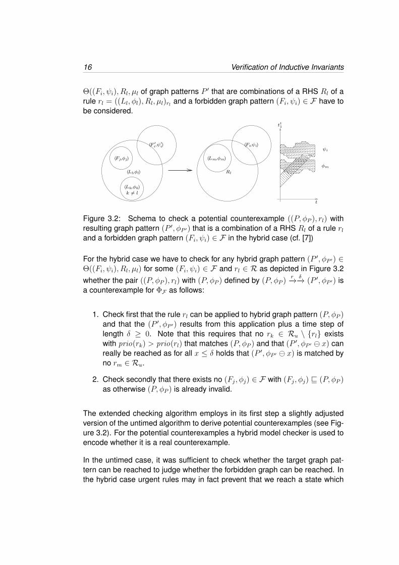
Θ((Fi, ψi), Rl, µl of graph patterns P ′ that are combinations of a RHS Rl of arule rl = ((Ll, φl), Rl, µl)rl and a forbidden graph pattern (Fi, ψi) ∈ F have tobe considered.
Figure 3.2: Schema to check a potential counterexample ((P, φP ), rl) withresulting graph pattern (P ′, φP ′) that is a combination of a RHS Rl of a rule rland a forbidden graph pattern (Fi, ψi) ∈ F in the hybrid case (cf. [7])
For the hybrid case we have to check for any hybrid graph pattern (P ′, φP ′) ∈Θ((Fi, ψi), Rl, µl) for some (Fi, ψi) ∈ F and rl ∈ R as depicted in Figure 3.2whether the pair ((P, φP ), rl) with (P, φP ) defined by (P, φP )
r−→ δ−→ (P ′, φP ′) isa counterexample for ΦF as follows:
1. Check first that the rule rl can be applied to hybrid graph pattern (P, φP )and that the (P ′, φP ′) results from this application plus a time step oflength δ ≥ 0. Note that this requires that no rk ∈ Ru \ {rl} existswith prio(rk) > prio(rl) that matches (P, φP ) and that (P ′, φP ′ x) canreally be reached as for all x ≤ δ holds that (P ′, φP ′ x) is matched byno rm ∈ Ru.
2. Check secondly that there exists no (Fj, φj) ∈ F with (Fj, φj) v (P, φP )as otherwise (P, φP ) is already invalid.
The extended checking algorithm employs in its first step a slightly adjustedversion of the untimed algorithm to derive potential counterexamples (see Fig-ure 3.2). For the potential counterexamples a hybrid model checker is used toencode whether it is a real counterexample.
In the untimed case, it was sufficient to check whether the target graph pat-tern can be reached to judge whether the forbidden graph can be reached. Inthe hybrid case urgent rules may in fact prevent that we reach a state which
HGTS Case 17
fulfills the conditions of the embedded forbidden hybrid graph patterns. There-fore, the encoding in form of a hybrid automata include transitions to a spe-cial urgent state that capture the behavior of urgent rules with higher priority((Lk, φk)). Therefore, in the hybrid automata model a path to the forbiddenhybrid pattern can only occur when no such higher priority rule has to be exe-cuted before.
Also the initial configuration before the rule application has to exclude that anyforbidden hybrid graph pattern ((Fj, ψj)) is already present as otherwise wewould not have the required transition from a valid configuration to an invalidone. This can be encoded by initial constraints for the initial state of the con-structed hybrid automata.
Due to both steps the hybrid automata can then be checked by the modelchecker to prove whether a rule application and subsequent time step couldreally result in an invalid configuration starting from a valid one (whether wehave a real counterexample).
sourcePattern
targetPattern
failureState
urgentState
¬φU
φU
φFi
φR∧timer ≥ 0
φinit
timer ≤ 0 ¬φFi∧
Figure 3.3: Generic automata for verifying the system’s continuous part
In Figure 3.3 the generic translation scheme to hybrid automata for some rule(LR, RR, φR) and some forbidden pattern (Fi, φFi) is depicted. The initial con-dition φinit guarantees that the source graph pattern is safe, φU holds if oneurgent transition is active. Let FS ⊆ F be the set of forbidden pattern thatcould be mapped into the source graph pattern and U ⊆ Ru the set of urgenttransitions, that could be mapped to the target graph pattern. Then we cangive φinit as φinit = φR ∧
∧Fs∈FS ¬φFs and φU as φu =
∨Ru∈U φRu . Thus the
failureState location can only be reached if we start in a correct source graphpattern, apply the rule and wait until the condition φFi holds. We use a clockcalled timer to force the hybrid automata to immediately leave the locationinitialState.
18 Verification of Inductive Invariants
3.2.1 Verification Results
The verification of the rules’ structural parts yields multiple possible witnessesagainst the system’s correctness. As mentioned above our verification ap-proach is twofold and the structural analysis gives us characteristic scenariosthat could result in an unsafe situations. However, to be sure that the found ex-ample prove the system to be incorrect we have to show that starting in a safesource graph pattern the application of the rule brings the system into a situa-tion where the condition of the forbidden pattern is reachable. With respect topossibly activated rules having a higher priority and urgent rules.
Figure 3.4: Possible counter example, derived from rule moveDC and forbid-den pattern collision
One possible counter example the structural verification found is depicted inFigure 3.4. The figures left hand side shows the source graph pattern and theright hand side the target graph pattern, respectively. The target graph patternhas been created by overlapping the right hand side of rule moveDC and theforbidden pattern collision at the nodes s1, s2 and t2, thus the whole patterncollision could be found in the rule’s right hand side. Reverse application ofthe rule led to the source graph pattern. In the source graph pattern we canfind only one forbidden pattern: The collision of two Shuttles while on two suc-ceeding Tracks.1 We require this forbidden pattern as the Shuttle’s length issupposed to be positive and thus it can happen that a Shuttle is physically attwo Tracks at the same time. In our system the Shuttle is only allowed to beat one Track at one point in time (we use the Shuttle’s front to determine thecurrent track).
1Note that the forbidden pattern noDC (cf. 2.4) does not match due to the existence of theDistanceCoordination instance.
HGTS Case 19
Listing 3.1: Hybrid automaton to counter example from Figure 3.4automaton GenericHybridGTS
contr var : s1 pos , s2 pos , s1 v , s2 v , s1 a , s2 a , v re f , pos re f ,t imer ;
parameter : d is tance , f a i l u r e ;synclabs : vo id ;loc sourcePat tern : while t<=0 wait { t imer ’ == 1} ;
when t imer >= 0 sync vo id do {pos re f ’ == s1 pos −d is tance − 2 & s1 pos ’ == s1 pos & s2 pos ’ == s2 pos &s2 v ’ == s2 v & s1 v ’ == s1 v & s1 a ’ == s1 a & s2 a ’== s2 a & v re f ’ == v r e f & f a i l u r e ’ == 0} gotot a r g e t P a t t e r n ;
loc t a r g e t P a t t e r n : while s1 pos − d is tance − s2 pos >= 0wait {s1 pos ’ == s1 v & s1 v ’ == s1 a & s1 a ’ == P ∗ (v r e f − s1 v ) & s2 v ’ == P 2 ∗ ( s1 pos − d is tance − 10 −s2 pos ) − Q 2 ∗ ( s2 v − 3 − s1 v ) & pos re f ’ == s1 pos ’ &
v re f ’ == 0} ;when s1 pos − d is tance − s2 pos <= 0 sync vo id do { f a i l u r e
’ == 1} goto f a i l u r e S t a t e ;loc f a i l u r e S t a t e : while t r ue wait { t r ue } ;loc u rg e n tT r an s i t i o n : while t r ue wait { t r ue } ;i n i t i a l l y : sourcePat tern & s1 pos > s2 pos + d is tance + 10 &
s2 pos > 0 & 60 < v r e f & v r e f < 200 & 60 < s1 v & s1 v< 200 & 3 <= s1 v − s2 v & s1 v − s2 v <= 3 & f a i l u r e ==0 & 5 < d is tance & d is tance < 10;
end
In the target graph pattern we do not find an urgent rule that could restrictthe reachability of the failure state. Thus, the hybrid automaton we have tocheck using PHAVer is the one shown in Listing 3.1. In this automaton mainlythree locations are of interest: sourcePattern, targetPattern and failureState.The automaton’s initial state is given by the line starting with initially :... . Inthe initial state all velocities are in their boundaries (we assume that velocitiesare less than 200 km/h) and that the shuttles s1 and s2 have not collided,yet. The situation we want to verify starts with the moment in time, when therule is applied. Hence, the automaton has to leave the location sourcePatternimmediately. We can express this in PHAVer with the use of a timer variableand a corresponding location invariant. Initially the timer is set to zero andthe invariant is given as timer ≤ 0. The guards of the transitions leaving thesourcePattern location are fulfilled if timer ≥ 0 holds.
20 Verification of Inductive Invariants
Following the active transition to the targetPattern location only resets the shut-tle’s timer t, which stores the time the shuttle is at the current Track. All otherstatements within the transitions do condition specify that no other attributevalues are changed. The automaton can stay at the targetPattern location aslong as the forbidden pattern’s condition is not fulfilled, i.e. the Shuttles havenot collided. If the forbidden pattern’s property is fulfilled the transition to thefailureState location becomes activated. This transition changes the value ofthe automaton’s failure parameter to 1. The reachability analysis we performusing PHAVer checks, whether a state is reachable where the failure param-eter’s value is set to 1. Performing this analysis on the automaton shown inListing 3.1 we find out that such a state (with failure set to 1) is not reachable,within the automaton. Thus, we showed that the possible counter example,provided by the structural analysis, is not a witness against the system’s cor-rectness.
3.3 Complete Checking
The complete algorithm performs this check for any given rule ((Ll, φl), Rl, µl)rl∈ R and forbidden graph pattern (Fi, ψi) ∈ F by computing the related set ofall possible target graph patterns (Θ((Fi, ψi), Rl, µl) and then derives the re-lated source graph patterns. The above outlined cases are then employed todecide whether the source graph pattern (P, φP ) represents potentially safegraphs that can be transformed into unsafe graphs by applying r plus a timestep δ. If so, the pair ((P, φP ), r) is a valid counterexample.
In the application example we had a total of six rules and fourteen forbiddenpatterns. We had to introduce several forbidden pattern to show that the multi-plicity constraints implicitly introduced through the system’s class diagram aresatisfied, too. We further modeled rules that allow the Shuttles to accelerateand decelerate if they are in SpeedControlMode. However, the algorithm hadto check 64 pairs of rules and forbidden pattern. While he did this, he found37 possible counterexamples, which we manually translated into a hybrid au-tomaton for PHAVer and checked whether the failureState location could bereached. Between the possible counter examples were lots of similarities,which were mainly introduced due to isomorphism.
Chapter 4
Related Work
A number of related approaches for the verification of systems with structuralchanges like our earlier work [6] exist which do not support time dependentbehavior. Further some approaches directly adresses the verification of hy-brid systems, mostly relying on hybrid automata for the input specification.DynAlloy [12] extends Alloy [16] in such a way that changing structures canbe modeled and analyzed. For operations and required properties in form oflogical formulae it can be checked whether given properties are operationalinvariants of the system. An approach which has been successfully applied toverify service-oriented systems [4] is the one of Varro et al. It transforms visualmodels based on graph theory into a model-checker specific input [20]. A moredirect approach is GROOVE [19] by Rensink where the checking works directlywith the graphs and graph transformations. However, these approaches do notfully cover the problem as they require an initial configuration and only supportfinite state systems (or systems for which an abstraction to a finite state modelof moderate size exist).
There are only first attempts that address the verification of infinite state sys-tems with changing structure: In [3] graph transformation systems are trans-formed into a finite structure, called Petri graph which consists of a graph anda Petri net, each of which can be analyzed with existing tools for the analy-sis of Petri nets. For infinite systems, the authors suggest an approximation.The approach is not appropriate for the verification of the coordination of au-tonomous vehicles even without time, because it requires an initial configura-tion and the formalism is rather restricted, e.g., rules must not delete anything.Partner graph grammars are employed in [5] to check topological propertiesof the platoon building. The partner abstraction is employed to compute over
21
22 Related Work
approximations of the set of reachable configurations using abstract interpre-tation. However, the supported partner graph grammars restrict not only themodel but also the properties which can be addressed a priori. It is to be notedthat in addition to the mentioned limitations, both approaches do not supporttime as approached in this paper.
The only approach we are aware of that addresses structural changes as wellas time is Real-Time Maude [18] which is based on rewriting logics. The toolsupports the simulation of a single behavior of the system as well as boundedmodel checking of the complete state space, if it is finite. Again, the require-ment of having an initial configuration and the limitation to finite state modelsexcludes that the real-time coordination of autonomous vehicles can be fullycovered.
Concerning the direct verification of hybrid system the work of Henzinger etal. [2, 15] is the first to mention. However, although we could have in princi-ple used the tool HyTech we decided to use the improved implementation byFrehse [11] called PHAVer. Both tools are applicable for the verification of thecounterexamples the structural analysis presents but are not applicable to theverification task in general.
There exist many approaches to cover the modeling of complex hybrid behav-ior sucvh as CHARON, Masaccio, HybridUML, UMLh, HyROOM, HyCharts,Mechatronic UML or Ptolemy (cf. [14]). However, none of them provides thecapability to describe dynamic structures as required for the considered classof cyber-physical systems.
Chapter 5
Conclusion and Future Work
We have presented an approach that is able to model cyber-physical systemswith dynamic structure. By extending established graph transformation sys-tems theory towards hybrid systems, the approach permits to capture suchsystems at a reasonable high level of abstraction and to describe how the adhoc formation of tightly coupled cyber-physical subsystems can happen.
Furthermore, the also presented extended checking approach for inductiveinvariants enables us to provide guarantees for such cyber-physical systemswith dynamic structure if the number of different types (not instances) of tightlycoupled cyber-physical subsystems is not too large.
5.1 Future Work
Future work will look for more convenient means to specify the local hybrid be-havior in form of models and differential equations (e.g., supporting algebraicones) as well as exploiting more sophisticated analysis tools for the checksrequired for the inductive invariants that would allow us to relax the constraintson the differential equations for checking inductive invariants.
For the case of discrete GTS we have recently developed an algorithm tocheck the existence of patterns, i.e. application of a set of graph-rules pre-servers the patterns, [9], in contrast to showing the absence of forbidden pat-
23
24 Conclusion and Future Work
terns, as we have done in this report. We still have to evaluate to which extentthis approach has to be adopted to be applicable for HGTS, too.
We also plan to apply our approach to a cyber physical system of small robotsto evaluate the applicability of our approach. An important aspect of this isto ensure that the verified system models remain valid models of the runningcode. One possibility to narrow the gap between model and code is the imple-mentation of an story diagram interpreter for embedded systems.
Bibliography
[1] Rajeev Alur, C. Coucoubetis, Thomas A. Henzinger, and Pei-Hsin Ho.Hybrid Automata: an algorithmic approach to the specification and ver-ification of hybrid systems. In R.L. Grossmann, A. Nerode, Anders P.Ravn, and Hans Rischel, editors, Hybrid Systems I, volume 736 of Lec-ture Notes in Computer Science, pages 209–229. Springer Verlag, 1993.
[2] Rajeev Alur, Thomas A. Henzinger, and Pei-Hsin Ho. Automatic Sym-bolic Verification of Embedded Systems. IEEE Transactions on SoftwareEngineering, 22:181–201, 1996.
[3] Paolo Baldan, Andrea Corradini, and Barbara Konig. A Static AnalysisTechnique for Graph Transformation Systems. In Proc. CONCUR, volume2154 of LNCS, pages 381–395. Springer, 2001.
[4] Luciano Baresi, Reiko Heckel, Sebastian Thone, and Daniel Varro. Mod-eling and Validation of Service-Oriented Architectures: Application vs.Style. In ESEC/FSE-11: Proceedings of the 9th European software en-gineering conference held jointly with 11th ACM SIGSOFT internationalsymposium on Foundations of software engineering, pages 68–77, NewYork, NY, USA, 2003. ACM.
[5] Jorg Bauer and Reinhard Wilhelm. Static Analysis of Dynamic Commu-nication Systems by Partner Abstraction. In Proceedings of the 14th In-ternational Symposium, SAS 2007, Kongens Lyngby, Denmark, August22-24, 2007, volume 4634 of Lecture Notes in Computer Science, pages249–264. Springer Berlin / Heidelberg, 2007.
[6] Basil Becker, Dirk Beyer, Holger Giese, Florian Klein, and DanielaSchilling. Symbolic Invariant Verification for Systems with Dynamic Struc-tural Adaptation. In Proc. of the 28th International Conference on Soft-ware Engineering (ICSE), Shanghai, China. ACM Press, 2006.
25
26 BIBLIOGRAPHY
[7] Basil Becker and Holger Giese. On Safe Service-Oriented Real-TimeCoordination for Autonomous Vehicles. In In Proc. of 11th InternationalSymposium on Object/component/service-oriented Real-time distributedComputing (ISORC), pages 203–210. IEEE Computer Society Press, 5-7May 2008.
[8] Michel Charpentier. Composing Invariants. In Proc. of International Sym-posium of Formal Methods Europe, volume 2805 of Lecture Notes inComputer Science, pages 401–421. Springer, 2003.
[9] Johannes Dyck. Increasing expressive power of graph rules and condi-tions and automatic verification with inductive invariants. Master’s thesis,Hasso-Plattner-Institut fur Softwaresystemtechnik, Universitat Potsdam,July 2012.
[10] National Science Foundation. Program Announcements & Informa-tion: Cyber-Physical Systems, September 2008. http://www.nsf.gov/publications/pub_summ.jsp?ods_key=nsf08611.
[11] Goran Frehse. PHAVer: Algorithmic Verification of Hybrid Systems PastHyTech. In Hybrid Systems: Computation and Control, volume 3414 ofLecture Notes in Computer Science, pages 258–273. Springer Berlin /Heidelberg, 2005.
[12] Marcelo Fabian Frias, Juan Pablo Galeotti, Carlos Lopez Pombo, andNazareno Aguirre. DynAlloy: Upgrading Alloy with actions. In Proc. ofInternational Conference of Software Engineering, pages 442–451. ACM,2005.
[13] Holger Giese. Modeling and Verification of Cooperative Self-adaptiveMechatronic Systems. In Fabrice Kordon and Janos Sztipanovits, edi-tors, Reliable Systems on Unreliable Networked Platforms - 12th Mon-terey Workshop 2005 . Laguna Beach, CA, USA, September 22-24,2005. Revised Selected Papers, volume 4322 of Lecture Notes in ComputerScience, pages 258–280. Springer Verlag, 2007.
[14] Holger Giese and Stefan Henkler. A Survey of Approaches for the Vi-sual Model-Driven Development of Next Generation Software-IntensiveSystems. Journal of Visual Languages and Computing, 17(6):528–550,December 2006.
[15] Thomas A. Henzinger, Pei-Hsin Ho, and Howard Wong-Toi. HyTech: AModel Checker for Hybrid Systems. Software Tools for Technology Trans-fer, 1:110–122, 1997.
[16] Daniel Jackson. Alloy: a lightweight object modelling notation. ACMTransactions on Software Engineering and Methodology, 11(2):256–290,2002.
[17] Hans J. Kohler, Ulrich A. Nickel, Jorg Niere, and Albert Zundorf. Integrat-ing UML Diagrams for Production Control Systems. In Proc. of the 22ndInternational Conference on Software Engineering (ICSE), Limerick, Ire-land, pages 241–251. ACM Press, 2000.
[18] Peter Olveczky and Jose Meseguer. Specification and Analysis of Real-Time Systems Using Real-time Maude. In Tiziana Margaria and MichelWermelinger, editors, Proceedings on Fundamental Approaches to Soft-ware Engineering (FASE2004), volume 2984 of Lecture Notes in Com-puter Science. Spinger-Verlag Heidelberg, 2004.
[19] Arend Rensink. Towards Model Checking Graph Grammars. In MichaelLeuschel, S. Gruner, and S. Lo Presti, editors, 3rd Workshop on Auto-mated Verification of Critical Systems (AVoCS), Technical Report DSSE–TR–2003–2, pages 150–160. University of Southampton, 2003.
[20] Daniel Varro. Automated formal verification of visual modeling languagesby model checking. Software and System Modeling, 3(2):85–113, May2004.
Aktuelle Technische Berichte des Hasso-Plattner-Instituts
Band ISBN Titel Autoren / Redaktion
63 978-3-86956-
204-9 Theories and Intricacies of Information Security Problems
Anne V. D. M. Kayem, Christoph Meinel (Eds.)
62 978-3-86956-212-4
Covering or Complete? Discovering Conditional Inclusion Dependencies
Jana Bauckmann, Ziawasch Abedjan, Ulf Leser, Heiko Müller, Felix Naumann
61 978-3-86956-194-3
Vierter Deutscher IPv6 Gipfel 2011 Christoph Meinel, Harald Sack (Hrsg.)
60 978-3-86956-201-8
Understanding Cryptic Schemata in Large Extract-Transform-Load Systems
Alexander Albrecht, Felix Naumann
59 978-3-86956-193-6
The JCop Language Specification
Malte Appeltauer, Robert Hirschfeld
58 978-3-86956-192-9
MDE Settings in SAP: A Descriptive Field Study
Regina Hebig, Holger Giese
57 978-3-86956-191-2
Industrial Case Study on the Integration of SysML and AUTOSAR with Triple Graph Grammars
Holger Giese, Stephan Hildebrandt, Stefan Neumann, Sebastian Wätzoldt
56 978-3-86956-171-4
Quantitative Modeling and Analysis of Service-Oriented Real-Time Systems using Interval Probabilistic Timed Automata
Christian Krause, Holger Giese
55 978-3-86956-169-1
Proceedings of the 4th Many-core Applications Research Community (MARC) Symposium
Peter Tröger, Andreas Polze (Eds.)
54 978-3-86956-158-5
An Abstraction for Version Control Systems
Matthias Kleine, Robert Hirschfeld, Gilad Bracha
53 978-3-86956-160-8
Web-based Development in the Lively Kernel
Jens Lincke, Robert Hirschfeld (Eds.)
52 978-3-86956-156-1
Einführung von IPv6 in Unternehmensnetzen: Ein Leitfaden
Wilhelm Boeddinghaus, Christoph Meinel, Harald Sack
51 978-3-86956-148-6
Advancing the Discovery of Unique Column Combinations
Ziawasch Abedjan, Felix Naumann
50 978-3-86956-144-8
Data in Business Processes Andreas Meyer, Sergey Smirnov, Mathias Weske
49 978-3-86956-143-1
Adaptive Windows for Duplicate Detection Uwe Draisbach, Felix Naumann, Sascha Szott, Oliver Wonneberg
48 978-3-86956-134-9
CSOM/PL: A Virtual Machine Product Line
Michael Haupt, Stefan Marr, Robert Hirschfeld
47 978-3-86956-130-1
State Propagation in Abstracted Business Processes
Sergey Smirnov, Armin Zamani Farahani, Mathias Weske
46 978-3-86956-129-5
Proceedings of the 5th Ph.D. Retreat of the HPI Research School on Service-oriented Systems Engineering