+ All Categories
Home > Documents > Cyber-Security Solutions for Ensuring Smart Grid Distribution Automation … · Distribution...

Cyber-Security Solutions for Ensuring Smart Grid Distribution Automation … · Distribution...

Date post: 28-Mar-2020
Category:
Upload: others
View: 18 times
Download: 2 times
Share this document with a friend
169
Tampere University of Technology Cyber-Security Solutions for Ensuring Smart Grid Distribution Automation Functions Citation Jafary, P. (2018). Cyber-Security Solutions for Ensuring Smart Grid Distribution Automation Functions. (Tampere University of Technology. Publication; Vol. 1534). Tampere University of Technology. Year 2018 Version Publisher's PDF (version of record) Link to publication TUTCRIS Portal (http://www.tut.fi/tutcris) Copyright In reference to IEEE copyrighted material which is used with permission in this thesis, the IEEE does not endorse any of Tampere University of Technology's products or services. Internal or personal use of this material is permitted. If interested in reprinting/republishing IEEE copyrighted material for advertising or promotional purposes or for creating new collective works for resale or redistribution, please go to http://www.ieee.org/publications_standards/publications/rights/rights_link.html to learn how to obtain a License from RightsLink. Take down policy If you believe that this document breaches copyright, please contact [email protected], and we will remove access to the work immediately and investigate your claim. Download date:07.04.2020
Transcript

Tampere University of Technology

Cyber-Security Solutions for Ensuring Smart Grid Distribution Automation Functions

CitationJafary, P. (2018). Cyber-Security Solutions for Ensuring Smart Grid Distribution Automation Functions.(Tampere University of Technology. Publication; Vol. 1534). Tampere University of Technology.

Year2018

VersionPublisher's PDF (version of record)

Link to publicationTUTCRIS Portal (http://www.tut.fi/tutcris)

CopyrightIn reference to IEEE copyrighted material which is used with permission in this thesis, the IEEE does notendorse any of Tampere University of Technology's products or services. Internal or personal use of thismaterial is permitted. If interested in reprinting/republishing IEEE copyrighted material for advertising orpromotional purposes or for creating new collective works for resale or redistribution, please go tohttp://www.ieee.org/publications_standards/publications/rights/rights_link.html to learn how to obtain a Licensefrom RightsLink.

Take down policyIf you believe that this document breaches copyright, please contact [email protected], and we will remove accessto the work immediately and investigate your claim.

Download date:07.04.2020

Peyman JafaryCyber-Security Solutions for Ensuring Smart GridDistribution Automation Functions

Julkaisu 1534 • Publication 1534

Tampere 2018

Tampereen teknillinen yliopisto. Julkaisu 1534 Tampere University of Technology. Publication 1534 Peyman Jafary Cyber-Security Solutions for Ensuring Smart Grid Distribution Automation Functions Thesis for the degree of Doctor of Science in Technology to be presented with due permission for public examination and criticism in Sähkötalo Building, Auditorium SA203, at Tampere University of Technology, on the 7th of September, at 12 noon. Tampereen teknillinen yliopisto - Tampere University of Technology Tampere 2018

Doctoral candidate: Peyman Jafary

Laboratory of Electrical Energy Engineering Faculty of Computing and Electrical Engineering Tampere University of Technology Finland

Supervisors: Sami Repo, Professor Laboratory of Electrical Energy Engineering Faculty of Computing and Electrical Engineering Tampere University of Technology Finland Hannu Koivisto, Professor Laboratory of Automation and Hydraulic Engineering Faculty of Engineering Sciences Tampere University of Technology Finland

Pre-examiners: Chen-Ching Liu, Professor

Faculty of Electrical Engineering & Computer Science Washington State University United States Matti Lehtonen, Professor Faculty of Electrical Engineering Aalto University Finland

Opponents: Lars Nordström, Professor Department of Electric Power and Energy Systems Royal Institute of Technology (KTH) Sweden Matti Lehtonen, Professor Faculty of Electrical Engineering Aalto University Finland

ISBN 978-952-15-4103-2 (printed) ISBN 978-952-15-4176-6 (PDF) ISSN 1459-2045

i

Abstract

The future generation of the electrical network is known as the smart grid. The

distribution domain of the smart grid intelligently supplies electricity to the end-users

with the aid of the decentralized Distribution Automation (DA) in which intelligent

control functions are distributed and accomplished via real-time communication between

the DA components. Internet-based communication via the open protocols is the latest

trend for decentralized DA communication. Internet communication has many benefits,

but it exposes the critical infrastructure’s data to cyber-security threats. Security attacks

may not only make DA services unreachable but may also result in undesirable physical

consequences and serious damage to the distribution network environment. Therefore, it

is compulsory to protect DA communication against such attacks. There is no single

model for securing DA communication. In fact, the security level depends on several

factors such as application requirements, communication media, and, of course, the cost.

There are several smart grid security frameworks and standards, which are under

development by different organizations. However, smart grid cyber-security field has not

yet reached full maturity and, it is still in the early phase of its progress. Security protocols

in IT and computer networks can be utilized to secure DA communication because

industrial ICT standards have been designed in accordance with Open Systems

Interconnection model. Furthermore, state-of-the-art DA concepts such as Active

distribution network tend to integrate processing data into IT systems.

This dissertation addresses cyber-security issues in the following DA functions:

substation automation, feeder automation, Logic Selectivity, customer automation and

ii

Smart Metering. Real-time simulation of the distribution network along with actual

automation and data networking devices are used to create hardware-in-the-loop

simulation, and experiment the mentioned DA functions with the Internet communication.

This communication is secured by proposing the following cyber-security solutions.

This dissertation proposes security solutions for substation automation by developing

IEC61850-TLS proxy and adding OPen Connectivity Unified Architecture (OPC UA)

Wrapper to Station Gateway. Secured messages by Transport Layer Security (TLS) and

OPC UA security are created for protecting substation local and remote communications.

Data availability is main concern that is solved by designing redundant networks.

The dissertation also proposes cyber-security solutions for feeder automation and Logic

Selectivity. In feeder automation, Centralized Protection System (CPS) is proposed as the

place for making Decentralized feeder automation decisions. In addition, applying IP

security (IPsec) in Tunnel mode is proposed to establish a secure communication path for

feeder automation messages. In Logic Selectivity, Generic Object Oriented Substation

Events (GOOSE) are exchanged between the substations. First, Logic Selectivity

functional characteristics are analyzed. Then, Layer 2 Tunneling over IPsec in Transport

mode is proposed to create a secure communication path for exchanging GOOSE over

the Internet. Next, communication impact on Logic Selectivity performance is

investigated by measuring the jitter and latency in the GOOSE communication. Lastly,

reliability improvement by Logic Selectivity is evaluated by calculating reliability indices.

Customer automation is the additional extension to the smart grid DA. This dissertation

proposes an integration solution for the heterogeneous communication parties (TCP/IP

and Controller Area Network) in Home Area Network. The developed solution applies

Secure Socket Layer in order to create secured messages.

The dissertation also proposes Secondary Substation Automation Unit (SSAU) for real-

time communication of low voltage data to metering database. Point-to-Point Tunneling

Protocol is proposed to create a secure communication path for Smart Metering data.

The security analysis shows that the proposed security solutions provide the security

requirements (Confidentiality, Integrity and Availability) for DA communication. Thus,

communication is protected against security attacks and DA functions are ensured. In

addition, CPS and SSAU are proposed to distribute intelligence over the substations level.

iii

Preface

This study was carried out in the Laboratory of Electrical Energy Engineering at Tampere

University of Technology during 2013-2017. The primary supervisor of this dissertation

has been Prof. Sami Repo. I wish to express my deepest gratitude to Prof. Sami Repo for

his unceasing support, technical supervision and guidance throughout this dissertation.

Additionally, I would like to thank my co-supervisor Prof. Hannu Koivisto for his

valuable comments during this study.

I would also like to express my appreciation to Prof. Pekka Verho for his helpful technical

advices in one project, as well as to all the co-authors of my papers, especially senior

researchers Mikko Salmenperä and Jari Seppälä.

Furthermore, I wish to thank all the university personnel who facilitated the

administrative regulations. Terhi. S, Nitta. L, Elina. O, Maikku. K, Päivi. O, Ulla. S, Jukka.

K and Mirva. S, to name but a few.

My greetings also go to all my friends who have made these past few years such a pleasant

experience. Last but not least, my sincere thanks go to my parents, my sister and my

brother for their constant encouragement and motivation during the years it has taken to

complete my studies. Finally, I dedicate this dissertation to my much-beloved wife.

Tampere, December 2017

Peyman Jafary

iv

Table of Contents

ABSTRACT ................................................................................................................... I

PREFACE .................................................................................................................... III

TABLE OF CONTENTS ............................................................................................... IV

LIST OF FIGURES ....................................................................................................... X

LIST OF TABLES ...................................................................................................... XIII

LIST OF PUBLICATIONS ......................................................................................... XIV

LIST OF ABBREVIATIONS ........................................................................................ XV

1 INTRODUCTION ................................................................................................. 1

1.1 Motivation and Objectives ............................................................................... 2

1.1.1 Distribution Automation Components ..................................................... 3

1.1.2 Communication and Security ................................................................. 4

1.1.3 Research Scope .................................................................................... 4

1.1.4 Multidisciplinary Research Objectives .................................................... 6

1.1.4.1 Multidisciplinary Research Objectives – Part 1 .................................. 6

1.1.4.2 Multidisciplinary Research Objectives – Part 2 .................................. 8

1.2 Contributions ................................................................................................... 9

1.3 Publications ................................................................................................... 10

1.4 Structure of Dissertation ................................................................................ 10

2 SMART GRID DA FUNCTIONS ......................................................................... 11

v

2.1 Remote Control and Monitoring ..................................................................... 11

2.1.1 Supervisory Control and Data Acquisition (SCADA) ............................. 11

2.1.2 Distribution Management System (DMS) ............................................. 11

2.1.3 Distribution Information Center (DIC) ................................................... 12

2.2 Substation Automation .................................................................................. 13

2.2.1 Primary Substation Automation ............................................................ 13

2.2.1.1 Modern Substation Architecture ....................................................... 13

2.2.1.2 Specific Requirements for Substation LAN ...................................... 15

2.2.2 Secondary Substation Automation ....................................................... 15

2.3 MV Fault Management .................................................................................. 17

2.3.1 Centralized Architecture (Restoration by DMS) .................................... 17

2.3.2 Peer-to-Peer Architecture (Restoration by Logic Selectivity) ................ 19

2.3.3 Feeder Automation............................................................................... 21

2.4 Customer Automation ................................................................................... 23

2.4.1 HEMS for Demand-Side Integration ..................................................... 23

2.4.2 HEMS Communication in Home Area Network .................................... 24

2.5 Smart Metering ............................................................................................. 25

2.5.1 Smart Metering Data for Smart Grid DA Applications ........................... 25

2.5.2 Smart Metering Architecture in the Distribution Network ...................... 26

3 INDUSTRIAL ICT AND UTILITY INTERNET ..................................................... 27

3.1 Communication Standards in Decentralized DA ............................................ 27

3.1.1 IEC 60870-5-104 .................................................................................. 27

vi

3.1.2 IEC 61850 ............................................................................................ 28

3.1.2.1 SV, GOOSE and MMS .................................................................... 28

3.1.2.2 Horizontal and Vertical Communication ........................................... 29

3.1.3 IEC 62439-3 PRP ................................................................................ 30

3.1.3.1 Link Redundancy Entity (LRE) ......................................................... 31

3.1.3.2 Routing in PRP Network .................................................................. 31

3.1.4 CAN and CANopen .............................................................................. 32

3.1.5 IEC 62056 DLMS/COSEM ................................................................... 33

3.1.6 IEC Common Information Model (CIM) ................................................ 34

3.2 Utility Internet for Decentralized DA............................................................... 34

4 CYBER-SECURITY IN DA COMMUNICATION ................................................. 36

4.1 Risk Analysis and Management in DA Communication ................................. 36

4.2 Security Vulnerabilities in DA Communication ............................................... 37

4.3 Risk Assessment in DA Communication ....................................................... 38

4.4 Security Requirements in DA Communication ............................................... 38

4.5 Security Solutions for DA Communication ..................................................... 39

4.5.1 Defense-in-Depth Strategy ................................................................... 40

4.5.2 Common Security Techniques for DA Communication ......................... 41

4.5.2.1 Cryptography ................................................................................... 41

4.5.2.2 Virtual LAN (VLAN) .......................................................................... 42

4.5.2.3 Firewall and Demilitarized Zone (DMZ) ............................................ 42

4.5.2.4 Virtual Private Network (VPN) .......................................................... 43

vii

5 RESEARCH METHODOLOGY AND MATERIALS ............................................ 44

5.1 Smart Grid Testbed ....................................................................................... 44

5.1.1 Real Time Simulation of the Distribution Network ................................. 44

5.1.2 Automation Devices for Experiencing DA Functions ............................. 44

5.1.3 Remote Monitoring and Control of the Distribution Network ................. 45

5.1.4 Internet for Data Communication .......................................................... 45

5.2 Software Tools and Application Development ............................................... 45

5.3 Utilization of Test setups for Cyber-Security Studies ..................................... 45

6 SECURITY SOLUTIONS ENSURING DA FUNCTIONS .................................... 46

6.1 Smart Grid DA Function 1: Substation Automation ........................................ 46

6.1.1 Primary Substation – SAS Local Communication ................................. 46

6.1.1.1 Use-Case: Local Monitoring in IEC 61850-based Substation ........... 46

6.1.1.2 Security Vulnerabilities .................................................................... 47

6.1.1.3 Security Requirements .................................................................... 47

6.1.1.4 Security Solution.............................................................................. 48

6.1.1.5 Final Security Analysis..................................................................... 49

6.1.2 Primary Substation – SAS Remote Communication ............................. 50

6.1.2.1 Use-case: Remote Monitoring in IEC 61850-based Substation........ 51

6.1.2.2 Security Vulnerabilities .................................................................... 52

6.1.2.3 Security Requirements .................................................................... 52

6.1.2.4 Security Solution.............................................................................. 52

6.1.2.5 Final Security Analysis..................................................................... 54

viii

6.2 Smart Grid DA Function 2: Feeder Automation ............................................. 55

6.2.1 Use-Case: Decentralized Feeder Automation ...................................... 55

6.2.2 Security Vulnerabilities ......................................................................... 56

6.2.3 Security Requirements ......................................................................... 57

6.2.4 Security Solution .................................................................................. 57

6.2.5 Final Security Analysis ......................................................................... 58

6.3 Smart Grid DA Function 3: Logic Selectivity .................................................. 58

6.3.1 Use-Case: GOOSE-based Logic Selectivity ......................................... 59

6.3.1.1 Algorithm Testing by Hardware-in-the-Loop Simulation ................... 59

6.3.1.2 Algorithm Performance Evaluation .................................................. 60

6.3.1.3 Algorithm Timing Evaluation ............................................................ 63

6.3.2 Security Vulnerabilities ......................................................................... 64

6.3.3 Security Requirements and Automation Requirements ........................ 64

6.3.3.1 Security Requirements .................................................................... 64

6.3.3.2 Automation Real-Time Requirements .............................................. 64

6.3.3.3 PICARD Requirements .................................................................... 64

6.3.4 Security Solution and Automation Solution ........................................... 65

6.3.4.1 Security Solution.............................................................................. 65

6.3.4.2 Automation Real-Time Solution ....................................................... 65

6.3.5 Final Security-Analysis and Final Automation-Analysis ........................ 66

6.3.5.1 Security Analysis ............................................................................. 66

6.3.5.2 Automation Real-Time Analysis ....................................................... 66

ix

6.3.5.3 PICARD Analysis ............................................................................. 67

6.3.6 Effect of Dependable Logic Selectivity on Reliability Indices ................ 68

6.4 Smart Grid Function 4: Customer Automation ............................................... 70

6.4.1 Use-Case: HEMS-BMS Integration in HAN .......................................... 70

6.4.2 Security Vulnerabilities ......................................................................... 71

6.4.3 Security Requirements ......................................................................... 72

6.4.4 Security Solution .................................................................................. 72

6.4.5 Final Security Analysis ......................................................................... 73

6.5 Smart Grid DA Function 5: Smart Metering ................................................... 73

6.5.1 Use-Case: Smart Metering Communication in SSAU ........................... 73

6.5.2 Security Vulnerabilities ......................................................................... 74

6.5.3 Security Requirements ......................................................................... 74

6.5.4 Security Solutions ................................................................................ 74

6.5.4.1 Security Solution for NAN Communication....................................... 74

6.5.4.2 Security Solution for WAN Communication ...................................... 75

6.5.5 Final Security Analysis ......................................................................... 76

6.5.5.1 Security Analysis in NAN Communication........................................ 76

6.5.5.2 Security Analysis in WAN Communication ....................................... 76

6.6 Discussion ..................................................................................................... 77

7 CONCLUSIONS ................................................................................................ 79

REFERENCES ........................................................................................................... 81

x

List of Figures

Fig 1. Data communication between DA components in decentralized DA ............................. 3

Fig 2. The research scope of this dissertation ...................................................................... 5

Fig 3. Modern Primary substation architecture [37] ........................................................... 14

Fig 4. Modular structure of the Secondary Substation Automation Unit (SSAU) ................... 16

Fig 5. Data communication to/from SSAU ....................................................................... 16

Fig 6. Supply restoration by DMS ................................................................................... 18

Fig 7. An application of standardized GOOSE-based Logic Selectivity ................................ 19

Fig 8. The GOOSE-based Logic Selectivity algorithm ....................................................... 20

Fig 9. Feeder automation approaches and the required devices for each approach.................. 22

Fig 10. Demand-Side Integration decision levels ............................................................... 23

Fig 11. HEMS communication in Home Area Network...................................................... 24

Fig 12. Smart Metering architecture in the distribution network .......................................... 26

Fig 13. The structure [66] of the IEC 104 message in the Ethernet Frame ............................. 27

Fig 14. Mapping IEC61850 data to the OSI model layers ................................................... 28

Fig 15. Destination MAC address for multicast SV and GOOSE communication .................. 29

Fig 16. DAN, SAN and Redundancy Box in the PRP network ............................................ 30

Fig 17. Ethernet frame with Redundancy Control Trailer ................................................... 31

Fig 18. The OBject Identification System (OBIS) structure ................................................ 33

Fig 19. Utility Internet for decentralized DA data communication ....................................... 35

Fig 20. Framework for risk analysis and management in DA communication ....................... 37

xi

Fig 21. Defense-in-depth strategy .................................................................................... 40

Fig 22. Lab setup for modeling an IEC 61850-based Primary substation .............................. 46

Fig 23. PRP networks design for high data availability ...................................................... 48

Fig 24. Secured messages for the substation local communication ....................................... 49

Fig 25. Primary substation remote communication ............................................................ 51

Fig 26. OPC UA for substation remote communication to control center .............................. 52

Fig 27. The OPC UA security [107] model ....................................................................... 53

Fig 28. Security for the substation remote communication .................................................. 53

Fig 29. Secure connection establishment between substation and control center .................... 54

Fig 30. Communication architecture for Decentralized feeder automation ............................ 56

Fig 31. Secure communication path for Decentralized feeder automation ............................. 57

Fig 32. Lab setup for testing the GOOSE-based Logic Selectivity algorithm ........................ 59

Fig 33. Real-Time network monitoring for the permanent fault between SS2 and SS3 ........... 61

Fig 34. The operation times of CB IEDs in the first stage of the algorithm ........................... 62

Fig 35. The operation times in the GOOSE-based Logic Selectivity algorithm ...................... 63

Fig 36. The calculated operation times in the ten times tests ............................................... 63

Fig 37. A QoS measurement with 200 kbps additional UDP traffic ...................................... 67

Fig 38. A QoS measurement with 10 kbps additional UDP traffic ....................................... 67

Fig 39. PICARD analysis for the GOOSE-based Logic Selectivity ...................................... 68

Fig 40. HEMS and BMS with disparate communication interfaces and protocols .................. 70

Fig 41. Communication entities in HEMS-BMS integration ............................................... 71

Fig 42. Secured messages for HAN communication .......................................................... 72

xii

Fig 43. SSAU for real-time transmission of the LV network data ........................................ 74

Fig 44. Secured messages for NAN communication in Smart Metering ................................ 75

Fig 45. Secure communication path for WAN communication in Smart Metering ................. 75

xiii

List of Tables

Table I. Description of the information systems in DIC ..................................................... 12

Table II. IEC 61850 Horizontal and Vertical Communication in the Station bus ................... 30

Table III. Security services in the OSI model layers [96] ................................................... 39

Table IV. Secure session establishment between the TLS Client and Proxy Server ............... 50

Table V. Comparison of security in the substation remote communication ........................... 54

Table VI. The assumptions for the simulated electrical network in RTDS ............................ 68

xiv

List of Publications

[P1] P. Jafary, S. Repo and H. Koivisto, “Secure Integration of the Home Energy

Management System to the Battery Management System in the Customer Domain of

the Smart Grid”, In IEEE Power and Energy Society (PES) General Meeting, National

Harbor, MD, United States, July 2014.

[P2] P. Jafary, M. Salmenperä, S. Repo and H. Koivisto, “OPC UA security for

protecting substation and control center data communication in the distribution domain

of the smart grid”, In IEEE International Conference on Industrial Informatics (INDIN),

Cambridge, United Kingdom, July 2015.

[P3] P. Jafary, S. Repo and H. Koivisto, “Secure communication of smart metering data

in the smart grid secondary substation”, In IEEE Innovative Smart Grid Technologies -

Asia (ISGT ASIA), Bangkok, Thailand, November 2015.

[P4] P. Jafary, S. Repo and H. Koivisto, “Security solutions for smart grid feeder

automation data communication”, In IEEE International Conference on Industrial

Technology (ICIT), Taipei, Taiwan, March 2016.

[P5] P. Jafary and et al, “Secure Layer 2 Tunneling Over IP for GOOSE-based Logic

Selectivity”, In IEEE International Conference on Industrial Technology (ICIT),

Toronto, Canada, March 2017.

[P6] P. Jafary, J. Seppälä, S. Repo and H. Koivisto, “Security and Reliability Analysis

of a Use Case in Smart Grid Substation Automation Systems”, In IEEE International

Conference on Industrial Technology (ICIT), Toronto, Canada, March 2017.

xv

List of Abbreviations

AAA Authentication, Authorization, Accounting

ADA Advanced Distribution Automation

AES Advance Encryption Standard

AIS Aggregator Information System

AMI Advanced Metering Infrastructure

AMM Automated Meter Management

AMR Automated Meter Reading

ANM Active Network Management

APCI Application Protocol Control Information

APDU Application Protocol Data Unit

API Application Programming Interface

ASDU Application Service Data Unit

BMS Battery Management System

CAN Controller Area Network

CC Control Center

CIA Confidentiality, Integrity, Availability

CIM Common Information Model

CIS Customer Information System

COSEM COmpanion Specification for Energy Metering

CPS Centralized Protection System

CRC Cyclic Redundancy Check

CYSEMOL Cyber Security Modeling Language

DA Distribution Automation

DAN Doubly Attached Node

DER Distributed Energy Resources

DG Distributed Generation

DIC Distribution Information Center

DLMS Device Language Message specification

DMS Distribution Management System

DMZ Demilitarized Zone

DO Data Object

DSO Distribution System Operator

EAP Extensible Authentication Protocol

EMS Energy Management System

ENISA European Network and Information Security Agency

ESP Encapsulating Security Payload

FDIR Fault Detection Isolation and Restoration

GIS Geographic Information Systems

xvi

GOOSE Generic Object Oriented Substation Event

HAN Home Area Network

HEMS Home Energy Management System

HMI Human Machine Interface

HSR High-availability Seamless Redundancy

HV High Voltage

IE Industrial Ethernet

IEC TC57 International Electrotechnical Commission Technical Committee 57

IED Intelligent Electronic Device

IKE Internet Key Exchange

IP Internet Protocol

IPRP IP Parallel Redundancy Protocol

IPSEC Internet Protocol Security

ISA International Society of Automation

ISO International Organization for Standardization

ISP Internet Service Provider

IT & OT Information and Operational Technologies

L2TPv3 Layer 2 Tunneling Protocol version 3

LAN Local Area Network

LD Logical Device

LN Logical Node

LRE Link Redundancy Entity

LV Low Voltage

MAC Media Access Control

MDC Meter Data Concentrator

MIS Metering Information System

MMS Manufacturing Message Specification

MV Medium Voltage

NAN Neighborhood Area Network

NIS Network Information System

NIST National Institute of Standards and Technology

NMT Network Management

NTP Network Time Protocol

OA Object Attribute

OBIS OBject Identification System

OPC DA Open Platform Communications Data Access

OPC UA OPen Connectivity Unified Architecture

OSI Open Systems Interconnection

P2CySeMoL Predictive, Probabilistic Cyber Security Modeling Language

PC Personal Computer

PD Physical Device

xvii

PDO Process Data Objects

PPTP Point-to-Point Tunneling Protocol

PRP Parallel Redundancy Protocol

PS Primary Substation

PTP Precision Time Protocol

QoS Quality of Service

RCT Redundancy Control Trailer

RPDO Receive PDO

RTDS Real Time Digital Simulator

RTU Remote Terminal Unit

SAIDI System Average Interruption Duration Index

SAIFI System Average Interruption Frequency Index

SAN Single Attached Node

SAS Substation Automation Systems

SCADA Supervisory Control and Data Acquisition

SCL Substation Configuration Language

SDO Service Data Objects

SFO Special Function Objects

SNTP Simple Network Time Protocol

SS Secondary Substation

SSAU Secondary Substation Automation Unit

SSL Secure Socket Layer

SV Sampled Values

TCP Transmission Control Protocol

TLS Transport Layer Security

TPDO Transmit PDO

UDP User Datagram Protocol

USB Universal Serial Bus

VLAN Virtual LAN

VPN Virtual Private Network

WAN Wide Area Network

WIS Work Information System

XML Extensible Markup Language

1

1 INTRODUCTION

The motivation behind the smart grid is to improve the efficiency of the electricity supply

chain in several economically feasible ways such as increasing the hosting capacity for

the renewable energy sources, supplying the acceptable-quality power to the customers,

the utilization of the heat pumps, the smart charging of the electric vehicles and enhancing

the general reliability of the grid. The distribution domain [1] of the smart grid links

electricity from the transmission domain to the customer domain. Traditional distribution

systems relied on a low level of automation with basic data communication capabilities.

However, smart grid Distribution Automation (DA) takes advantage of the latest

advances in ICT systems in order to enable efficient operation of the very much more

complex distribution grid of the future. Smart grid DA attempts to create an intelligent

and controllable distribution grid by deploying two-way ICT capable of transmitting real-

time operational data, rather than just historical data. This results in real-time monitoring

and control of the remote distribution elements, thus enabling intelligent operation of the

distribution network. ICT systems provide access to the distribution network data needed

for a variety of purposes such as monitoring, supervision, protection, control, condition

monitoring, operational planning, maintenance and asset management.

The DA is performed at different levels [2] such as the substation level, feeder level,

distribution network level, control center level and Distribution System Operator (DSO)

level. Information exchange and integration are the key enablers for adding new smart

grid functions to DA. ICT systems create the required interaction between the distribution

network applications and the components. DA ICT systems contain a heterogeneous

network of networks including automation networks, computer networks, cellular

2

network and wireless networks. On the one hand, employing various network types

satisfies the interaction requirements for the emerging DA applications. On the other hand,

DA data communication suffers from the security vulnerabilities to which all these

different networks are susceptible. Data exchange in ICT systems must be secure because

the overall performance of the DA is dependent on the validity of the real-time data that

is transmitted over the ICT systems.

Several organizations are currently studying smart grid security requirements including

DA communication security. Many of the challenges of smart grid security have already

been identified by the European Network and Information Security Agency (ENISA) in

[3]. The International Electrotechnical Commission Technical Committee 57 (IEC TC57)

Working Group 15 particularly focuses on communication security and has developed

the IEC 62351 [4] standard of the Information Security for Power System Control

Operations. Furthermore, security requirements for DA applications have been generally

defined in NISTIR 7628 [5] by the National Institute of Standards and Technology (NIST).

The International Society of Automation (ISA) has also created the ISA99 committee,

which has developed the ISA/IEC-62443 [6] standard of Network and System Security

for Industrial Process Measurement and Control. The International Organization for

Standardization (ISO) along with the IEC have jointly developed the ISO/IEC TR 27019

[7] standard of Information Security Management Systems for Energy Utility Industry.

1.1 Motivation and Objectives

The state-of-the-art smart grid approaches propose a decentralized [8] DA architecture

that applies hierarchical and distributed control architecture at different levels of the

distribution network. Real-time communication between the various levels is necessary

in order to accomplish intelligent DA functions. The decentralized DA enables efficient

integration between DA components and systems by transmitting standard-based

messages through an open networking infrastructure. Therefore, cyber-security has

become vitally important and security measures must be designed to achieve a reliable

and efficiently functioning DA.

3

1.1.1 Distribution Automation Components

There are several components that contribute to the decentralized DA process. The main

DA sub-components are Primary substation automation, field-disconnectors automation

(feeder automation), Secondary substation automation, customer automation, Data

Collectors, Distribution Information Center (DIC) and the distribution control center.

Real-time data communication within each of these sub-components, as well as between

them, is essential if the smart grid DA goals are to be accomplished. Fig 1 shows different

DA components and the communication between them required by the decentralized DA.

Fig 1. Data communication between DA components in decentralized DA

Decentralized DA requires both Vertical integration (to control center) and Horizontal

integration (between DA components). In Fig 1, DA data communication can be

categorized into four main groups. The first category includes control center and

substation/field communication, substation-to-substation communication and substation

to field communication. The second, customer and Data Collectors communication. The

third is Data Collectors and DIC communication, while the fourth is control center and

DIC communication. While the first communication category often contains Supervisory

Control and Data Acquisition (SCADA) messages to/from remote devices, the second

4

category includes LV network measurement data as well as the data from the customers’

Distributed Energy Resources (DER). In the third category, collected data from several

customers are transmitted to the respective databases in the DIC. The fourth

communication category relates to the Distribution Management System (DMS) that

sends/receives the required information for realizing intelligent automation functions.

1.1.2 Communication and Security

Connectivity is necessary for proposing new smart grid DA functions that require

integrating new resources into the DA operation. For instance, modern [8] DA concepts

(for example, Active distribution network) are more interested in the real-time visibility

of process data (for example, DER data). Therefore, Information and Operational

Technologies (IT & OT) have to be merged to improve the operational efficiency and to

decrease the integration costs. Smart grid DA facilitates integration by using standard

data communication and networking protocols. Internet-based data exchange, i.e.

communication over Internet Protocol (IP), is regarded as the latest trend for decentralized

DA communication because of its compatibilities with the latest generation of SCADA

[9], Internet-of-Things [10] devices in the fields/customer sites, and integration methods

[11] for databases in DIC. Furthermore, modern automation (control) networks adapt to

the Ethernet and Transmission Control Protocol (TCP)/IP, and integrate to enterprise

networks [12] via IP-based communication.

Internet-based communication has many benefits, such as cost-effective connectivity and

interoperability between DA components. However, this communication also presents

cyber-security challenges [13] that can have physical consequences because of the Cyber-

Physical-System [14] nature of the smart grid. Security attacks [15] on the DA systems

may lead to industrial espionage, system malfunction, blackouts and serious damage to

the distribution network environment. All of the above points to the necessity of applying

cyber-security solutions that will ensure the reliable DA operation. The principles of

security must be taken into account in the planning, design and operational phases of DA.

1.1.3 Research Scope

As stated above, secure Internet communication is essential for the reliable integration of

DA components and the realization of smart grid DA functions. The following research

questions will define the research scope of this dissertation:

5

- Can we implement smart grid DA functions by exchanging information (even

non-IP protocols) on top of the IP and utilizing the existing networking

infrastructures in a way that satisfies the requirements for multiple actors such as

DSO, meter provider and customers?

- Can we use standardized IT security protocols and create dependable

communication for smart grid DA functions in which information security and

automation real-time requirements are met?

o It should be noted here that the main focus of this dissertation is on the

security requirements rather than the automation real-time requirements.

- Can we manage intelligent DA functions hierarchically within decentralized DA

by applying new automation solutions that support industrial ICT and distribute

decision-making over the distribution network?

Fig 2 depicts the research scope of this dissertation, which is a combination of smart grid

DA function, industrial ICT and information security.

Fig 2. The research scope of this dissertation

Concerning Fig 2, smart grid DA functions selected for this dissertation are substation

automation, feeder automation, Logic Selectivity, customer automation and Smart

Metering. Industrial ICT includes information integration via power-system automation

standards and Internet communication. Information security comprises applying IT

security protocols at different layers of the Open Systems Interconnection (OSI) model.

As can be seen in Fig 2, the research scope is a combination of three disciplines.

Consequently, the research objectives are multidisciplinary as they encompass a broader

range of issues than could be handled by a single discipline study that would focus more

deeply on a specific problem in just one of the aforementioned disciplines.

6

1.1.4 Multidisciplinary Research Objectives

This multidisciplinary research creates a link between the three disciplines outlined in Fig

2, and has two aims:

- Confidentiality, Integrity and Availability are defined as the high-level security

requirements for the smart grid information networks [5]. The first aim is to meet

these high-level security requirements for the local DA communication, as well

as remote DA communication over the Internet with deterministic behavior.

- The second aim is to provide real-time connectivity and distribute intelligence in

decentralized DA by proposing innovative solutions in the distribution substations.

These aims will be accomplished by fulfilling the following multidisciplinary research

objectives (Parts 1 and 2), which correspond to the above-mentioned aims, respectively.

1.1.4.1 Multidisciplinary Research Objectives – Part 1

Smart grid security is regarded as a new field of research, which is still in the early stage

of its development [16]. While the importance of smart grid security has been identified

and recommendations have been made by government and industry professionals in

[3][5], there is as yet no common security framework for protecting communication in

smart grid DA. Indeed, most of the DA communication standards have no built-in security

mechanisms since they were developed when cyber-security was not a big issue for the

industrial networks. For instance, the well-known IEC TC57 standards (such as IEC

60870-5-104, IEC 60870-6, IEC 61968 and IEC 61850) and DNP3 originally lacked

internal security mechanisms to provide end-to-end security. Because of this, IEC

subsequently published the IEC 62351 standard for handling the security of the TC57

standard series. Although the IEC 62351 standard does address some security

requirements, it is not yet in its final version and it is expected that further [17][18]

security mechanisms will be proposed. Consequently, the current smart grid DA

equipment has no support for IEC 62351, as it is recognized that it is still under

development and may yet undergo major changes.

Several security solutions have been proposed [19,20,21,22,23] for securing DA data

communication. The proposed security protocol in [19] protects DA data communication,

7

but it is a proprietary protocol, which means that there are issues concerning security

management and implementation. In [20][21], the addition of security extensions to the

SCADA communication protocols are proposed. However, the implementation is tedious

and requires upgrading of the Data link layer. Although secure aggregation protocols are

proposed for the hierarchical collection of metering data in [22][23], these are not reliable

enough and contain security vulnerabilities [16] relating to an attacker penetrating the

aggregation process and accessing large quantities of critical data by decrypting just one

single aggregation packet. Moreover, while a secure framework for data exchange in a

Home Area Network (HAN) has been proposed in [24] for similar nodes supporting

ZigBee, information integration for dissimilar nodes will also be required especially for

other HAN communication technologies of interest [25] such as the Ethernet.

Furthermore, the HAN communication in [24] still requires more reliable security

protocols in order to avoid the security issues implicit in ZigBee [26]. While the existing

security protocols in IT networks may not provide the security requirements for all the

DA application areas (for example, IT security protocols does not fully cover industrial

control security requirements), but they do secure DA data exchange (particularly DA

Internet communication) in many applications because of the following reasons.

First of all, the broadly used security mechanisms in computer networks are compatible

with DA data exchange because industrial ICT standards are based on the OSI model, and

automation networks also tend to integrate [12] enterprise networks to bridge the gap

between the automation and IT systems. Also, although automation networks differ [27]

from computer network concerning to real-time requirements and continues functioning,

there are also many similarities in terms of using widely accepted networking protocols

and technologies. In addition, there are differences [16] between a smart grid DA Internet

and the regular Internet in terms of traffic type, performance metrics, communication

model and more importantly timeliness of data delivery. However, recent advancements

in the Internet access technologies provide high-performance Internet with the increased

bandwidth that is able to deliver fresh [27] data to the decision-making elements in DA.

This dissertation addresses the applicability of IT and computer security solutions at

different layers of the OSI model in order to achieve secure DA communication through

the establishment of secured messages, secured communication paths or both. The

following multidisciplinary research objectives are defined in below:

8

To create secured messages for the communication in customer automation and

Primary substation automation.

To build secure communication paths for the communication in Smart Metering,

feeder automation and Logic Selectivity.

To evaluate substation’s remote communication security by alternative solutions:

secured messages and secure communication paths.

To investigate the impact of the communication network on Logic Selectivity

real-time performance.

To analyze the effect of dependable (Secure and Real-time) Logic Selectivity on

the distribution network’s reliability.

1.1.4.2 Multidisciplinary Research Objectives – Part 2

The decentralized DA enhances the robustness of the system by distributing the

intelligence (via investment in controllability and ICT) over different levels [8] of the

distribution network, such as substations. While the automation capabilities of Primary

substations are enhanced, Secondary substation automation is also initiated through the

addition of a new automation device, i.e. Secondary Substation Automation Unit (SSAU).

In Primary substation, the protection and automation systems are linked in order to

provide new functionalities such as the Centralized Protection System (CPS) that was

introduced by ABB. While different studies [28][29][30] have addressed CPS from the

protection algorithms’ perspective, it can also be applied to feeder automation function.

In Secondary substation, SSAU requirements were investigated in IDE4L [31] project

conducted in cooperation with Tampere University of Technology. SSAU supports the

advanced automation and ICT standards [32] used for creating new intelligent automation

functions [33]. In addition, it can also be applied in the Smart Metering Process.

The following multidisciplinary research objectives are defined:

To consider Primary substation in feeder automation decision-making and to

create Horizontal integration between CPS and filed-disconnector.

To consider Secondary substation in Smart Metering process and to create

Horizontal integration of SSAU with customer site and DIC.

9

1.2 Contributions

These contributions are related to the multidisciplinary research objectives-part 1:

Publication 1 develops an integration solution for heterogeneous communication

interfaces (Serial and Ethernet) and protocols (CANopen and TCP/IP) in HAN.

Mutual authentication over SSL is proposed for securing the HAN communication.

Publications 2 and 6 propose Station Gateway as the key device for providing

security in Primary substation’s local and remote communications. The local

communication is secured by developing the proxy server application (supports

both IEC61850 and TLS) in the Station Gateway. The remote communication

security is achieved by adding OPC UA wrapper functionality to the Station

Gateway and create end-to-end security via OPC UA security model. In addition,

Publication 6 evaluates security in the substation’s remote communication by

comparing security mechanisms in two application layer protocols (OPC UA and

IEC 60870-5-104) and two types of VPN (PPTP and IPsec).

Publications 3 and 4 establish secure communication paths for metering data and

Decentralized feeder automation messages by proposing PPTP and IPsec tunnels.

Publication 5 experiments assessment of standardized Logic Selectivity in which

protection, control and monitoring functions modelled with IEC61850 data model.

Next, proposes L2TPv3 over IPsec for establishing a secure communication path

for transmitting GOOSE messages over the Internet. In addition, it measures jitter

and delay in the GOOSE recorded traffic in order to analyze them for Logic

Selectivity real-time requirements. Finally, it calculates reliability indices (SAIFI

and SAIDI) in case of employing GOOSE-based Logic Selectivity.

These following contributions are assigned to the mentioned multidisciplinary research

objectives-part 2:

Publication 4 proposes CPS as the place for making Decentralized feeder

automation decisions.

Publication 3 proposes SSAU for real-time LV network data transmission

between smart meter and metering database.

10

1.3 Publications

There are six publications [P1]-[P6] listed in this dissertation. These publications were

prepared in accordance with the top-down approach: smart grid, distribution network, DA

function, communication and security. The author of this dissertation proposed all the

publications and was responsible for the preparation, writing and presentation of the

papers. The author has conducted all the research work with the following exceptions.

Prof. Sami Repo (as the primary supervisor) and Prof. Hannu Koivisto have been the

supervisors of the dissertation and their roles in the publications have involved general

discussion, guidance and commentary. In Publication 2, M. Salmenperä assisted in

configuring the OPC UA wrapper and provided comments on the same paper. In

Publication 5, O. Raipala helped for configuring the electrical protection parameters. M.

Salmenperä and J. Seppälä prepared the communication setup for the secure Internet

communication. They also commented on issues related to PICARD analysis as well as

writing some paragraphs about the tunneling protocol and security. S. Horsmanheimo, H.

Kokkoniemi-Tarkkanen and L. Tuomimäki analyzed the recorded traffic measurements

as well as writing a few paragraphs. The Logic Selectivity algorithm was invented and

implemented at the device level by A. Alvarez, F. Ramos, A. Dede, and D. D Giustina.

In Publication 6, J. Seppälä has commented on the security related issues.

1.4 Structure of Dissertation

Following this introduction, chapters 2 and 3 describe smart grid DA functions and the

industrial ICT discussed in the above publications. Chapter 4 explains cyber-security in

DA data communication, while Chapter 5 defines the research methodology and materials.

The security solutions ensuring smart grid DA functions are discussed in Chapter 6 and

the dissertation’ conclusion is presented in Chapter 7.

11

2 SMART GRID DA FUNCTIONS

This chapter provides the background information for realizing the smart grid DA

functions that are the focus of this dissertation.

2.1 Remote Control and Monitoring

High-level DA decisions are made by the control center applications that receive data

from remote distribution devices and DIC. The control center contains SCADA and DMS

applications that monitor and manage MV network operation. SCADA applies remote-

to-field communication for exchanging measurement data, status of switches and control

commands. DMS carries out remote-to-corporate communication with DIC in order to

exchange the data values required to perform intelligent functions.

2.1.1 Supervisory Control and Data Acquisition (SCADA)

SCADA enables control center to collect data from the remote facilities and to send

control instructions to them. The changes in SCADA architecture can be described as

shifting from Monolithic to Distributed to Networked generations [34]. In the traditional

Monolithic-SCADA, the Master Terminal Unit collects data from Remote Terminal Units

(RTUs) via Wide Area Network (WAN) by using manufacturer-dependent

communication protocols. A Monolithic-SCADA does not integrate the distribution

network data with other applications in the control center. In a Distributed-SCADA, a

LAN is used in the control center in order to share SCADA data with other network

components (like DMS) via proprietary protocols. Finally, the Networked-SCADA

utilizes an open network infrastructure and standard protocols [35], not only for

communicating with the remote field devices but also for interconnecting with the DMS.

2.1.2 Distribution Management System (DMS)

DMS [36] provides new DA functions by integrating process data (SCADA data) and the

distribution network data (geographic, network components and management data),

which are acquired from DIC databases. DMS has functionalities such as topology

management, real-time network analysis, automated outage planning, Volt/VAR

12

optimization, fault management and supply restoration. DMS has been developed

incrementally by adding new intelligent tasks that use existing distribution network data

to perform new functions. Realizing DMS tasks requires the use of SCADA real-time

data, which means that there must be data exchange between DMS and SCADA

applications. Several versions of DMS to SCADA integration have evolved over time.

While proprietary communication protocols were used in the initial versions,

standardized Application Programming Interface (API) i.e. Open Platform

Communications Data Access (OPC DA) has been used in later versions. The most recent

version applies Web Service interface with the messages defined in the IEC 61968.

Additionally, realizing DMS tasks requires the use of network data in DIC databases.

2.1.3 Distribution Information Center (DIC)

A distribution utility company maintains a number of information systems containing

data related to the customers, the network facilities, maintenance and the geographic

locations of the feeders. Moreover, smart grid application areas, such as Smart Metering

and Distributed Generation (DG), have presented new information systems that are

applied to modern DA and an Active distribution network [8]. Table I describes the

information systems in a DIC.

Table I. Description of the information systems in DIC

13

In Table I, DIC elements can categorized into two main groups. The first group, consisting

of Network Information System (NIS), Customer Information System (CIS), Geographic

Information Systems (GIS) handles static data. The second group, consisting of Work

Information System (WIS), Metering Information System (MIS) and Aggregator

Information System (AIS) for the relevant DSO, handles dynamic (real-time) data. These

information systems are used for statistical, commercial, billing and technical purposes.

2.2 Substation Automation

Substation Automation can be implemented in both Primary and Secondary substations.

Although most of the Substation Automation Systems (SAS) have been designed for

Primary substations, the potential of Secondary substation automation will also be utilized

more in any smart grid DA.

2.2.1 Primary Substation Automation

In Primary substation, SAS provides automation at both the substation and distribution

network levels. At the substation level, SAS creates local automation for voltage control,

reactive power compensation and automated switch sequences. At the distribution

network level, SAS systems send measurements, status of switches, disturbance recorders

and events to the control center. In addition, they receive control commands,

acknowledgments, settings, and configuration parameters from the control center.

Traditional SAS apply analog signals via hardwiring for receiving the feeder

measurements, and manufacturer-dependent Fieldbuses for exchanging data between the

substation relays. The Fieldbus interface presents substation data to the substation

computer and Remote Terminal Unit (RTU) for the local and remote usage, respectively.

However, in a modern substation, the entire substation data is exchanged digitally

between the measurement, protection and control devices via the substation’s LAN.

2.2.1.1 Modern Substation Architecture

A modern substation LAN contains three logical levels: Process level, Bay level and

Station level [37]. The Process level includes measurement transformers and sensors that

provide process data via the network communication interface, rather than through analog

14

hard wiring. Intelligent Electronic Devices (IEDs) are located at the Bay level. These

IEDs are the latest substation automation devices, and are intelligent, programmable and

support advanced ICT protocols. Examples of such IEDs include the feeder/busbar

protection relay and the bay/voltage controller. The Station level consists of monitoring

and higher level automation devices including Human Machine Interface (HMI),

substation computer, and Station Gateway. These substation levels are connected via

Industrial Ethernet (IE) switches in which measurement transformers, IEDs and

automation applications are able to communicate through a single Ethernet network using

the uniform, interoperable [38] communication protocol that is the IEC 61850 standard.

In Fig 3, the IE switches are also linked together via a redundant network topology, such

as a ring, in order to increase substation data availability.

Fig 3. Modern Primary substation architecture [37]

In Process level, measurement transformers publish current and voltage values as

digitized Sampled Values (SV) in the IEC 61850-9-2 format. At the Bay level, the

intended IED subscribes the published values and performs the protection function. Bay

level IEDs also exchange data with other IEDs for monitoring and control purposes.

Station level is the place at which the substation LAN is connected to a remote network.

There are two other terms in a substation LAN, which need to be defined: Process bus

and Station bus. Process bus is intended for communication between the Process and Bay

levels, while the Station bus refers to communication between the Bay and Station levels.

15

2.2.1.2 Specific Requirements for Substation LAN

There are a number of similarities between a substation LAN and an ordinary computer

LAN. However, the SAS imposes specific requirements, time synchronization and

network redundancy, on the substation LAN standards. The on-time delivery of data to

substation IEDs and outdoor devices requires an extremely precise time-synchronization

method. The most recent substation IEDs support Ethernet technology and are able to use

the same network to exchange both process data and timing information. Therefore, a

Network Time Protocol (NTP) or a Simple Network Time Protocol (SNTP) can be used

for time synchronization. The accuracy of these protocols is within the millisecond range,

but does not satisfy the extreme time-demanding applications such as Process bus SV

(IEC 61850-9-2) and Synchrophasor (IEEE C37.118 and IEC 61850-90-5) applications

[40][41]. These applications require time synchronization accuracy at the microsecond

range. The IEEE 1588v2 Precision Time Protocol (PTP) [39] provides the required level

of accuracy and should be used for the time synchronization of substation LAN devices.

In addition to the above, network redundancy solutions with extremely fast recovery

times should be used in a substation LAN because data availability is critical for the

continuous operation of the IEDs. Although Spanning Tree Protocol and Rapid Spanning

Tree Protocol are often used to manage redundant topologies in a regular computer LAN,

they are not suitable for substation LAN because of their long recovery times, which can

take several seconds. The IEC 62439 standard defines suitably fast redundancy Ethernet

protocols [42] such as Media Redundancy Protocol, Parallel Redundancy Protocol (PRP),

High-availability Seamless Redundancy (HSR), Cross-network Redundancy Protocol,

Beacon Redundancy Protocol and Distributed Redundant Protocol. In a substation LAN,

the best solutions are HSR [43] and PRP [44] because they provide zero recovery time.

2.2.2 Secondary Substation Automation

In a distribution network, a substation that transforms MV to LV is known as a Secondary

substation. Legacy Secondary Substations mainly include MV/LV transformers and fuses

for protecting the LV feeders, but there is no automation, or at best only simple

automation functions such as that provided by a typical RTU. However, Secondary

Substation automation [45] will become more important in future DA, and will make

these substations capable of advanced automation and communication functionalities.

16

This is achieved by using an SSAU that provides monitoring and control functions at

Secondary substation level. The SSAU has new smart grid functions, such as fault current

measurement, fault indicators, optimization of power flow, power quality control and LV

grid management. The requirements for the next-generation SSAUs have been studied in

the IDE4L project [46], which was carried out by participating Tampere University of

Technology. An SSAU includes various functional modules, as is shown in Fig 4.

Fig 4. Modular structure of the Secondary Substation Automation Unit (SSAU)

The SSAU includes four main modules: the Communication, Database, Calculation and

Application Modules. The Communication Module handles the integration of SCADA

and third-party devices to SSAU. This module is also used for local time synchronization

of the SSAU via the use of NTP, SNTP or IEEE 1588v2 PTP. The Database Module can

be either a Relational Database Management System or a Time Series Database. The

Database Module is the data hub in the SSAU, which receives data from third-party

devices and provides data for internal and external applications. Fig 5 shows an example

of data communication to/from an SSAU using metering and SCADA protocols.

Fig 5. Data communication to/from SSAU

The Calculation Module includes processor for data processing, running programs and

protocols. An industrial computer with Linux or Microsoft Windows operating system

17

can be used as the hardware for SSAU. Application Module includes intelligent

algorithms for distributing DMS functionality over the Secondary substation level.

2.3 MV Fault Management

The MV fault management process involves three main steps: fault detection, fault

isolation and supply restoration. Fault detection is realized by a local protection IED. In

the fault isolation step, the fault is located and the protection IED isolates the faulty area

by sending a trip command to its circuit breaker. In the restoration step, the distribution

network’s topology is changed in order to restore power to the rest of network.

In a fault condition, power is disrupted within one part of the radial distribution network

and the affected customers experience an outage. In this situation, the DSO enhances

service continuity by using backup feeders that restore power to the affected customers.

Service continuity can be enhanced by utilizing several factors in the Design,

Implementation and Operation phases of the distribution network. In Design phase, MV

feeders are designed in accordance with the Open Ring Structure, in which the feeder’s

topology is radial but structured as a ring by allocating a normally open switch. The Open

Ring Structure is applied for designing back-up feeders for power restoration. In

Implementation phase, protection IEDs must be configured to be Selective, which means

only a minimal part of the network has to be isolated during the fault occurrence.

Protection IEDs provide Selectivity via two main methods: time-based Selectivity, which

configures the operational delay, or communication-based Selectivity, which exchanges

blocking messages [47]. In the Operation phase, there are two approaches [48] for

increasing service continuity: Fault Detection Isolation and Restoration (FDIR) and Logic

Selectivity. These methods can be implemented in Centralized or Peer-to-Peer

architectures. Centralized architecture applies Vertical integration while Peer-to-Peer

architecture uses Horizontal integration to accomplish their restoration decisions.

2.3.1 Centralized Architecture (Restoration by DMS)

In a fault condition, service continuity can automatically be realized with the FDIR

method, which applies coordinated interactions between the IEDs and the switching

devices. In [49], various solutions are proposed for FDIR. The main challenge in FDIR is

18

automatic restoration after fault detection and isolation. DMS can act as the central

location for making restoration decisions during the FDIR process. Below, the FDIR and

restoration steps are explained for the fault condition shown in Fig 6.

Fig 6. Supply restoration by DMS

Protection IED 1 detects a short circuit current and is activated. This results in the opening

of the feeder 1 circuit breaker and the subsequent outage experienced by the customers

connected to feeder 1. Then, IED 1 sends the value of the measured-fault-current to the

SCADA as an event. Next, the SCADA informs the DMS about the received value from

IED 1. The DMS requires this value (measured-fault-current) to automatically estimate

the fault location in the distribution network. The DMS then communicates with the NIS,

which contains the distribution network’s static data, including the feeder 1 data.

In the NIS, the fault currents have been previously calculated (calculated-fault-currents)

for all the feeder 1 zones: Primary substation to Disconnector 1 (D1), D1 to D2, and D2

to the Secondary substation. The DMS receives the calculated-fault-currents from the NIS

and compares them with the measured-fault-current received from SCADA. The fault

location is automatically estimated to be where these values overlap. Then, the DMS runs

its supply restoration algorithm and makes intelligent restoration decisions, i.e. opening

D1 and closing D3. Next, the DMS informs SCADA to execute its restoration decisions

by sending control commands to the remote disconnectors (D1 and D3). Finally, the DMS

sends an information request [50] to the WIS to dispatch a field crew for fault clearance.

The WIS sends an SMS/email/call to the crew to inform them about the fault location.

19

2.3.2 Peer-to-Peer Architecture (Restoration by Logic Selectivity)

Automatic supply restoration can be accomplished in a Peer-to-Peer architecture via

Horizontal integration, local processing and a distributed intelligence model. An example

of Peer-to-Peer architecture is Logic Selectivity, which exploits communication-based

selectivity and aims to maximize distribution network Selectivity, thus reducing the

number of outages and enabling faster reconfiguration during a fault condition. Logic

Selectivity is regarded as a highly efficient service continuity method, but it requires

substantial investment in feeder switching devices (replacing some switch disconnectors

with circuit breakers), substation IEDs, and the communication network between them.

In a fault condition, the operation time of the downstream IEDs must be less than that of

the upstream IEDs. Logic Selectivity provides protection Selectivity by using a blocking

signal that enables faster operation of the IEDs closer to the fault. This requires an

algorithm that is designed to consider blocking messages. Blocking messages block the

operation of the protection function in the upstream IEDs. These messages can be based

on a proprietary [51] protocol or they can be standard [52] blocking messages in the form

of Generic Object Oriented Substation Event (GOOSE).

Fig 7. An application of standardized GOOSE-based Logic Selectivity

Fig 7 shows an example of GOOSE-based Logic Selectivity application. The power flow

is from Primary (upstream) substation to Secondary (downstream) substations. All the

substations are equipped with IEDs that control the respective Circuit Breaker (CB IED)

and/or the attached Switch (SW IED). Implementing efficient Logic Selectivity requires

20

that there is a circuit breaker in at least one of the Secondary substations. Thus, a circuit

breaker is used in the first Secondary substation (SS1). Furthermore, all IEDs should be

equipped with some level of intelligence for executing the algorithm applied for fault

isolation and supply restoration. This algorithm’s design must take into account different

parameters relating to power direction, fault detection and switching devices.

Fig 8. The GOOSE-based Logic Selectivity algorithm

A summary of the Logic Selectivity algorithm [53] that is used for the network in Fig 7

is presented in Fig 8, above. This algorithm adapts [54] IEC61850 standard, and can be

21

defined in ISaGRAF [55]. The algorithm includes three main stages: fault isolation by

CB IEDs that open the closest breaker to the fault, further minimizing of the faulty section

by the SW IEDs that open the nearest switch to the fault, and service restoration by CB

IED that recloses the opened breaker after passing the reclosing time. There are also two

(fast and slow) reclosing times for handling temporary and permanent faults, respectively.

In the algorithm, T1 and T2 values have key roles and they make the operation time of

the upstream IEDs greater than that of the downstream IEDs. The number of GOOSE

subscriptions to each IED determines the X value and, consequently, T1 and T2 values.

The subscription of the upstream IEDs to the GOOSE messages published by the

downstream IED must occur within Waiting Time in T1 and T2 formulas. In other words,

the accurate operation of the algorithm requires the blocking message exchange between

IEDs within the Waiting Time, which is usually in millisecond range (e.g. 100ms).

A Peer-to-Peer architecture is considered more efficient than a Centralized architecture

because it has faster operation, autonomy (restoration decisions are locally made by the

field IEDs with no central controller), robustness (failure of one IED does not stop the

entire process), scalability (adaptation of system for adding new IEDs) and reliability

(decentralized decision making with no single-point-of-failure).

2.3.3 Feeder Automation

Both the Centralized and Peer-to-Peer architectures allow for the automatic operation of

the feeder switching devices, i.e. feeder automation as a subsection of DA. Feeder

automation is actualized through FDIR, Logic Selectivity, automatic transformer/feeder

load transfer, self-healing mechanisms and load balancing [56].

While some degree of feeder automation can be achieved using devices such as pole-

mounted reclosers and sectionalisers [37], fully automated feeder automation can be

fulfilled via the use of advanced IEDs interacting to make feeder automation decisions.

These decisions can be made in different locations in the distribution network such as the

control center, substations or even in-field. Publication 4 [P4] introduces four feeder

automation approaches: Semi-Automatic, Centralized, Decentralized and Distributed

explaining by Fig 9. This figure also includes a table that lists the devices required to

implement each approach, the required elements in the four highlighted points (A to D),

Disconnector 1 to 5 (D1 to D5), Primary Substation (PS) and Control Center (CC).

22

Fig 9. Feeder automation approaches and the required devices for each approach

Fig 9 illustrates a distribution network with two MV feeders designed in accordance with

the Open Ring Structure, in which D5 is normally open but the other disconnectors (D1

to D4) are normally closed. There are also four Secondary substations (SS1 to SS4). The

approaches to feeder automation are classified based on the location of the agent software

(which makes the feeder automation decisions), the intelligence level of the controlling

devices and the functionality of the switching devices. In Fig 9 the required devices are

proposed to achieve maximum distribution network reliability. However, in practice some

of these devices may be changed, depending on their cost and the load criticality.

23

2.4 Customer Automation

Customer domain [1] of the smart grid will include new application areas such as home

automation and smart charging [57] of the electrical vehicles. Furthermore, there is a shift

away from passive customers towards more active customers who participate in the

distribution network operation by providing their local generation and flexibility services

[8] to the market. Therefore, an intelligent customer automation and LV grid data

management system is required. Customer automation is a new dimension for DA. It

requires smart meters and HEMS, which provide customer data to the Data Collectors

that shown in Fig 1. These collected data are used for different purposes, including Active

distribution network [8] in which energy resources at the customer premises are

controlled in real-time in order to achieve the goals of Demand-side integration [58].

2.4.1 HEMS for Demand-Side Integration

Demand-side integration aims to meet the Active distribution network constraints by

managing customer loads through consumer load control, and by integrating local

generation capacity into the electricity network operations. The decision to integrate local

energy resources can be made at one of the four levels shown in Fig 10.

Fig 10. Demand-Side Integration decision levels

Each level has its own role in the complete system and the higher levels always co-

ordinate operation at the lower levels. These different levels have different ways of

24

making wise decisions, based on several factors such as DSO policy, specific use-case,

and the general scenario.

HEMS provides smart grid features such a, energy scheduling, load prioritization, home

appliance energy efficiency, local energy management and Demand-Side integration

decisions. Effective HEMS operation requires real-time data communication to both

Aggregator and customer’s energy resources via the Internet and HAN, respectively.

2.4.2 HEMS Communication in Home Area Network

A local network connecting a group of smart digital devices together within the

customer’s premises is called HAN. Smart home appliances, including HEMS, use the

HAN to carry out the communication requirements for home automation applications.

Fig 11. HEMS communication in Home Area Network

As can be seen from Fig 11, HEMS communicates with smart meter, electric vehicle,

smart home appliances and local energy resources. HEMS provides various automation

functions such as handling Demand-Side integration decisions by running an intelligent

energy management algorithm [59] [60] that controls local energy resources for various

situations, such as production following optimization and peak load management.

Home automation applications often require cost-effective and low-power-consumption

communication. Therefore, communication technologies with low data rates (up to

100kbps) and short communication ranges (up to 100m) are usually utilized in HAN [61].

HAN takes advantage of various wireless and wired networking technologies. Some

examples of the wireless technologies it uses [62] are WiFi, Z-Wave, ZigBee, Bluetooth

25

and 6LoWPAN. The wired technologies can be [62] Ethernet, HomePlug, HomePNA and

serial communication protocols such as Controller Area Network (CAN). Integration of

these different communication technologies and security are the key challenges in HAN.

These wired/wireless protocols can be used in HAN for communication of HEMS (level

2 in Fig 10) with local energy resources (level 1 in Fig 10) controller. This controller is

an IED in case of DER/DG, and a Battery Management System (BMS) in case of battery.

2.5 Smart Metering

A smart meter acts as a sensor that supports real-time bidirectional communication, which

is the essence of Smart Metering. The term Smart Metering implies a system that

automatically measures, records, analyzes and controls customers’ energy consumption

with the aid of advanced measurement and communication technologies [37]. Smart

Metering system includes three main elements: Automated Meter Reading (AMR),

Advanced Metering Infrastructure (AMI) and Automated Meter Management (AMM).

AMR utilizes digital data communication protocols/techniques for automatically

collecting data from the remote smart meters. AMI is the network architecture that

provides bidirectional data communication between smart meters and utility information

systems. AMM manages and stores customer data in the information systems.

2.5.1 Smart Metering Data for Smart Grid DA Applications

Traditional DA was only based on MV data, and was unaffected by LV network data.

However, smart grid DA also utilizes LV network data, as well as collecting information

from DER. Smart Metering is used to collect LV network data to accomplish new

application areas such as Active Network Management (ANM) and Advanced

Distribution Automation (ADA). ANM [8] is regarded as the newest distribution network

management model as it enhances the network’s hosting capacity by utilizing

decentralized DA and DER flexibility services. ANM operation requires both LV network

data and DER data, which are collected by Smart Metering and Aggregator, respectively.

In addition, the collected LV network data provided by Smart Metering adds advanced

LV automation functions to DA. LV data is applied for ADA in which control center

becomes capable of real-time LV grid monitoring and fault management [63]. The most

26

recent smart meters are able to indicate different LV network faults such as neutral

conductor fault, blown fuse, over/under voltage and wrong phase order [64]. ADA utilizes

smart meter data and provides LV network fault detection and location capabilities.

2.5.2 Smart Metering Architecture in the Distribution Network

Smart Metering in the distribution network includes automatically collecting LV network

data from smart meters and storing them in the respective database in DIC.

Fig 12. Smart Metering architecture in the distribution network

Fig 12 shows the Smart Metering architecture utilized in Finland. At the customer site,

smart meter communicates locally with HEMS and remotely with Meter Data

Concentrator (MDC) through Neighborhood Area Network (NAN). The smart meter’s

communication with the NAN can be carried out via wired network such as Power Line

Carrier and public telephone network or through wireless networks such as ZigBee, WiFi

and cellular networks. Communication network technologies with 100 kbps–10 Mbps

data rates and 10 km coverage distance are frequently used in NANs [61]. However, the

design of a NAN depends on several factors [65] such as the number of smart meters,

communication medium, cost, and the amount of data transfer. The NAN topology can

be varied but it must satisfy the timing requirements of the metering applications. For

instance, ad hoc network and mesh network can be designed as a NAN topology [65].

In Fig 12, MDC utilizes a WAN for transmitting data collected from several smart meters

to MIS database in DIC. The WAN supports higher data rates (10 Mbps–1Gbps) over

greater distances (100 km) than a NAN [61]. The WAN uses IP-based communication

that can be achieved through optical communication, cellular networks or satellite.

27

3 INDUSTRIAL ICT AND UTILITY INTERNET

Traditionally, a wide variety of communication protocols and separated networks were

utilized for communication in different components of DA. However, smart grid

improves integration by applying standard messages and communication network.

3.1 Communication Standards in Decentralized DA

Below, the most popular communication standards used in smart grid DA, which were

applied in publications [P1]-[P6], are explained.

3.1.1 IEC 60870-5-104

IEC TC 57 defines IEC 60870-5 standard series for process and telecontrol data

communication in electric power system. The latest version is IEC 60870-5-104 (IEC 104)

that is the most popular protocol utilized for electrical SCADA system communication in

European countries. In every IEC 104 communication system, there are two

communication parties: Controlling station and Controlled station. In case of DA,

Controlling station can be placed in the control center that receives data from Controlled

stations in remote substations/field devices. IEC 104 also defines two directions for data

transfer: control and monitor. It is also possible for a device to operate in the dual-mode.

TCP/IP transports IEC 104 data over a serial line or Ethernet. IEC 104 application layer

includes four groups of objects: Process, System, Parameter and File transfer information

[66]. Fig 13 illustrates the structure of IEC 104 messages transmitted by Ethernet frame.

Fig 13. The structure [66] of the IEC 104 message in the Ethernet Frame

Application Protocol Data Unit (APDU) consists of two [66] main parts: Application

Protocol Control Information (APCI) and Application Service Data Unit (ASDU). APCI

28

contains control information for managing the flow of communications. ASDU carries

the application data but only contains one of the four types of the above-mentioned

objects. One part within ASDU is Common address that is allocated to station. In addition,

every internal data element is also identified by its Information Object Address.

3.1.2 IEC 61850

IEC 61850 standard includes information model and abstract communication services that

facilitate integration between SAS from different manufactures. The hierarchical IEC

61850 data model [67] includes Physical Device (PD), Logical Device (LD), Logical

Node (LN), Data Object (DO) and Object Attributes (OA). PD is the device connects to

the communication network and may take the role of various LDs such as measurement,

protection, monitoring and control. Every LD includes one or more LNs that are related

to the various functions in SAS applications. There are LNs for measurements, circuit

breakers, switches, transformers, etc. LN supports one or multiple Dos, each with unique

name/s defined in the standard and related to the specific power system function. The

standard also defines sets of OA for every DO. Each OA has specific name and type

depending on its particular purpose. This hierarchical model provides a standard way of

defining SAS and their functions as an abstract data model. The abstract model can be

mapped to SV [68], GOOSE [69] and Manufacturing Message Specification (MMS) [69].

3.1.2.1 SV, GOOSE and MMS

The IEC 61850-7-2 presents the abstract communication service interfaces for the

information exchange. While IEC 61850-8-1 defines the mapping of IEC61850 datasets

to MMS and GOOSE protocols, IEC 61850-9-2 defines data mapping for the SV.

Fig 14. Mapping IEC61850 data to the OSI model layers

29

As can be seen in Fig 14, applications of SV and GOOSE are directly mapped to Ethernet

frame but MMS applications also utilizes TCP and IP layers.

The structure of SV and GOOSE messages are explained in [70] and [71], respectively.

SV and GOOSE are multicast messages that are published in the substation LAN and

intended IEDs or applications are subscribed. The publish-subscribe mechanism is based

on the destination multicast Media Access Control (MAC) address. Each address relates

to specific SV or GOOSE data. An IED is configured to subscribe to the specific multicast

address. Fig 15 depicts the hexadecimal values of destination multicast MAC address for

GOOSE and SV messages. The IEC TC 57 has defined these hexadecimal values.

Fig 15. Destination MAC address for multicast SV and GOOSE communication

MMS communication is based on client-server concept in which MMS client (for

example SCADA) and MMS server (for example IED) operate over TCP/IP. This

communication is typically used for read/write variables, reporting and file transfer.

MMS uses IEC 61850 communication services [72] , and defines standard objects,

messages, encoding rules and a set of protocols for exchanging messages between SAS.

3.1.2.2 Horizontal and Vertical Communication

In a modern substation, all of IEC 61850-compliant devices and their relationships can

be officially described by using Substation Configuration Language (SCL) [73] as the

XML files. The SCL files identify communication instructions such as sender, receiver,

period, content and method of exchanged messages among SAS. Communication in an

IEC 61850-compliant substation is categorized into two main groups: Horizontal and

Vertical communications, as described in Table II.

30

Table II. IEC 61850 Horizontal and Vertical Communication in the Station bus

Horizontal

Communication

Vertical

Communication

Scope Bay level Bay and Station levels

Direction IED to IED

IEDs and Station

Gateway/substation

computer/HMI

Data Content protection/interlocking control command to IEDs and

data/events reporting from IEDs

Message Type GOOSE MMS messages

OSI Layer Layer 2 Layer 3 and 4

Data Transmission Ethernet network Ethernet network

Communication Model Publish-Subscribe Client-Server

Time Criticality Highly time-critical Lesser time-critical

Information Flow SCL files SCL file

3.1.3 IEC 62439-3 PRP

PRP is a redundancy protocol with zero recovery time. PRP operates in the layer 2 of OSI

model and presents seamless redundancy for the layer 2 networks such as the SV and

GOOSE. It is based on the Ethernet frame duplication that is transparent to the higher

layer protocols. From topology point of view, PRP network can include both PRP and

non-PRP nodes. PRP node is called Doubly Attached Node (DAN) with two Ethernet

interfaces (A and B) connecting to two discrete LANs. Non-PRP device is called Single

Attached Node (SAN) and contains only one Ethernet interface, as shown in Fig 16.

Fig 16. DAN, SAN and Redundancy Box in the PRP network

SANs connect to only one LAN in a PRP network, and exchange data with other SANs

in the connected LAN. However, SANs can act like DANs via the Redundancy Box [44].

31

3.1.3.1 Link Redundancy Entity (LRE)

Every PRP device has two Ethernet interfaces but with the same MAC addresses.

Redundant transmission via two Ethernet controllers is managed by the Link Redundancy

Entity (LRE) software that duplicates each data frame [44]. A mechanism is required for

handling the duplicates at receiver side. There are two [74] methods for handling

duplicates: Duplicate Accept and Duplicate Discard. While receiver delivers both original

frames to the higher layer protocol in Duplicate Accept, LRE performs duplicate filtering

at Data Link layer in Duplicate Discard. This method is preferred mechanism since LRE

delivers just one data frame to the upper layer and offloads the application processor.

In Duplicate Discard, LRE recognizes duplicated frames with Redundancy Control

Trailer (RCT) [74]. In this method, the overhead bits are added to the duplicated Ethernet

frames as it is shown in Fig 17. In the RCT section of Ethernet pairs, the Sequence number

and Size fields are the same. The only field with a different value is the LAN identifier.

Fig 17. Ethernet frame with Redundancy Control Trailer

3.1.3.2 Routing in PRP Network

In some applications, IEDs connected to the substation LAN (designed based on PRP)

need to be logically categorized into different Virtual LANs (VLANs) or IP subnets,

based on their role and time-criticality. In these situations, data exchange between IEDs

requires a router to forward data packets from one subnet to another. However, routing

inside a PRP network is challenging. The routing challenge stem from the router operation

principle. First, router checks the destination IP address of the received packet. Then,

router checks its routing table to find the best matching interface for the received packet.

Finally, the received packet is encapsulated for router outgoing port. In the last step, router

replaces the source MAC address of the received packet with the source MAC address of

32

its outgoing port. This presents the challenge for PRP operation because PRP receiver

node applies the original source MAC address for duplicated frame detection [75].

Therefore, other mechanisms [75][76] are required for applying PRP in IP-based

communication. Examples of these mechanisms are a PRP-enabled router, PRP

modification algorithms and IP Parallel Redundancy Protocol (iPRP). In PRP-enabled

router, PRP should be supported either in router interfaces or tunneled by router over

networks. In PRP modification algorithm, adding the original source MAC address as the

new extension to RCT (in PRP frame) is proposed. Also, iPRP [76] presents a transport

layer approach by replicating User Datagram Protocol (UDP) packets in parallel paths.

Each packet is tagged with iPRP header containing the sequence number that is used for

duplication detection. iPRP header is located after IP and UDP headers of the data packet.

3.1.4 CAN and CANopen

CAN [77] is an industrial Serial communication protocol categorized in the group of

Fieldbuses. CAN supports distributed control in real-time in a robust way by broadcasting

short messages to the CAN bus network. There are four types of CAN frames transmitting

in the CAN bus: Data frame, Remote frame, Error frame and Overload frame. Up to 8

bytes of the application’s data can be transmitted in the Data frame, although the Remote

frame has no data field. The Error and Overload frames are quite similar, and they are

transmitted when an error is detected in the message or the node becomes too busy.

The CAN protocol stack includes layer 1 (Physical layer) and layer 2 (Data link Layer)

of OSI model. There are several application layer protocols for CAN such as CANopen

[78]. CANopen adapts CAN Physical and Data link layers and operates based on Master-

Slave data transmission. CANopen has its own upper application layer which presents

standardized objects for process data i.e. Process Data Objects (PDO), configuration data

i.e. Service Data Objects (SDO), predefined messages i.e. Special Function Objects (SFO)

as well as network administration data i.e. Network Management (NMT).

PDO are used for real-time communication of inputs and outputs up to 8 bytes of data.

There are two different kinds of PDO: Transmit PDO (TPDO) and Receive PDO (RPDO)

for sending and receiving process data, respectively. PDO can be transmitted cyclically,

or by change of state (event driven) or by polling i.e. reception of CAN request messages

such as a Remote message. PDOs to be transmitted/received are specified by PDO

33

mapping in the Object Dictionary. SDO is for transmission of parameter data that are non-

time-critical and exceed the 8 bytes’ limit of PDO. There are SDO for read/write of the

entries in the Object Dictionary, program download and configuring parameters. SFO are

for managing synchronization and errors. NMT are first messages used to start the CAN

bus and control the node operational states such as start, stop and reset.

CANopen protocol also comprises the Profile specification [78] concept that adds

capability of interchangeability and interoperability to the CANopen devices. CANopen

includes two types of Profile: Device and Communication profiles, which are based on

the Object Dictionary (systematically arranged objects) concept in which the device-

specific functions and communication mechanisms are described in the standard manner.

CANopen-based communication is a good candidate for embedded control applications

(such as BMS) because of its robustness and configuration flexibility.

3.1.5 IEC 62056 DLMS/COSEM

IEC 62056 DLMS/COSEM is a well-known metering protocol that can be used in a NAN.

The protocol uses client-server communication and provides modeling, messaging and

transporting of exchanged data between client and server [79]. DLMS/COSEM messages

can be transmitted either by Serial communication or by Ethernet and TCP/UDP protocols.

Device Language Message Specification (DLMS) is a general notion for abstract

modeling of the communicating parties. COmpanion Specification for Energy Metering

(COSEM) specifies collection of objects as the common language for metering data on

top of DLMS. DLMS message contains metering data or metering function with respect

to COSEM objects and data model. Similar objects form a COSEM Interface Class

containing particular attributes and methods that can be accessed by xDLMS services

such as Request, Response, GET (for reading an attribute) and SET (for writing an

attribute). These attributes/methods must be accessed by logical name referencing

includes ID of class, instance and attribute/method [80].

Fig 18. The OBject Identification System (OBIS) structure

34

Every metering data or function is uniquely represented as a code in the OBject

Identification System (OBIS) [80]. This structured code is meaningful sequence of six

numbers in hierarchical structure. Fig 18 shows general structure of the OBIS code.

OBIS codes are energy type specific. The first number (A) defines the energy type such

as electricity or gas metering, etc. The value of B is the input number using for separating

different sources. The C value denotes physical data items relating to the information

source concerned. The value of group D defines the processing method for example

integration. The E value is used for extra classification. The value of F is applied for

historical data definition or further classification. In this way, OBIS codes provide a

standard identification code for each metering data item that is exchanged between the

DLMS/COSEM client (for instance MDC) and server (for example smart meter).

3.1.6 IEC Common Information Model (CIM)

The IEC Common Information Model (CIM) [81] includes multiple standards used for

exchanging information between power system applications in different organizations.

The main IEC CIM standards are IEC 61970 and IEC 61968, which are used for Energy

Management System (EMS) and DMS in the transmission and distribution networks,

respectively. IEC 61968 aims to facilitate application integration in the distribution utility

companies. IEC 61968 presents a standard information model for creating the payload of

the messages exchanging between DSO applications such as DMS and SCADA.

IEC 61968 standard series (parts 1-9) describes CIM object model and architecture. CIM

data model is very large including high number of classes, attributes and associations.

However, only subset of the CIM is required in any specific context in power system

applications. Therefore, the concept of CIM Profiles [81] is introduced for every use-case

in order to prevent using unnecessary parts. CIM Profile only contains necessary classes,

attributes and associations requiring for the concrete implementation of the scenario.

3.2 Utility Internet for Decentralized DA

The Decentralized [8] DA architecture is very different from traditional Centralized

(control center-based) architecture. In decentralized DA, accomplishing new intelligent

35

functions requires real-time data communication of not only control center with field

devices but also between other DA components such as automation units [82] in Primary

substations, field disconnectors and substations, SSAU and smart meters, aggregator and

HEMS, and Data collectors with DIC.

The described communication protocols (in the previous Section) use utility Internet for

communication. Utility Internet signifies an IP-based network devoted to the utility using

for data exchange between DA components. A utility Internet can be a dedicated IP-based

network built for the utility, or one acquired as a service from the Internet Service

Provider (ISP). In Finland, ISP-based communication is the common and growing

method. Fig 19 shows a utility Internet with the communication elements in red.

Fig 19. Utility Internet for decentralized DA data communication

Utility Internet provides better DA data manageability, broad range of network services

and cost-effective method of interaction for the DA components. DA components use the

utility Internet and exchange DA data according to OSI model. This model organizes

network communication into seven layers. Each layer has its own protocols and adds

some info to the core data, which helps the receiving node to reconstruct the original data.

Security solutions must be designed for the utility Internet in order to ensure reliable

operation of DA and its subsections. Moreover, the utility Internet must meet the

automation real-time requirements for the time-critical DA applications.

36

4 CYBER-SECURITY IN DA COMMUNICATION

DA data network is a complex network that is used for supervising, protecting, controlling

and monitoring of the DA processes. DA data network includes communication within

DA components as well as communication between the DA components via utility

Internet. Security considerations have become essential for DA data network to ensure

the efficient and reliable operation of the distribution network. Any vulnerability in DA

data network could constitute a security threat [83] that malfunctions DA’s operation,

damage electrical devices or endanger human lives. This becomes even more vital in case

of SCADA communication [84] in which hacking of SCADA data presents a serious risk

that may result in significant economic losses. Thus, implementing security solutions for

DA communication is not just recommended, but is mandatory. Cyber-security solutions

aims to protect DA data network and utility Internet by applying a range of security

protocols, technologies, devices and policies. Security in DA data communication can be

methodically investigated using the security risk analysis and management process.

4.1 Risk Analysis and Management in DA Communication

The security risks could be analyzed in each DA use-case and the identified security

solutions are applied. Risk level in each DA use-case is determined by assessing the

associated security vulnerabilities and threats [85]. Vulnerability is a weakness in the

system or a lack of a countermeasure. Threat is the potential danger of the exploitation of

a system vulnerability. Risk is the probability of a threat agent exploiting a system’s

vulnerability and the associated consequences which could occur in the event of a security

attack [85]. Security attack is any action taken against an information resource aimed at

gaining unauthorized access, or destroying it. Security attacks can be divided into passive

attacks (access to the system data but no change to the system resources) and active

attacks (the attacker accesses the system information and changes the system resources).

In DA communication, security attacks may happen at any levels such as network,

communication stack, system, software, hardware, and physical levels [27][86]. Fig 20

shows the steps for the security risk analysis and management in DA data communication.

37

Fig 20. Framework for risk analysis and management in DA communication

The risk analysis phase investigates security vulnerabilities and identifies security threats

as well as assessing the risk and likelihood of possible security attacks. Risk assessment

evaluates the balance between the financial impact of the risk and the cost of mitigating

it. Risk mitigation involves reducing the risk level to an acceptable enough level for the

commercial operation of the business.

The risk management phase takes the outcome of Risk Assessment step and determines

the security requirements for a specific use-case. Then, security solutions are proposed

for risk mitigation and protecting data against different security attacks.

4.2 Security Vulnerabilities in DA Communication

In DA communication, there are security vulnerabilities in both utility Internet and data

communication within DA components. In utility Internet, transmitting DA data as the

plaintext (communication protocols without built-in security) may expose critical data to

the passive and active attacks. Such attacks could stop distribution network operation,

cause the protection system malfunction, decrease power supply quality, endanger

customer privacy and damage to critical infrastructure like Smart Metering.

There are also vulnerabilities in the data networks inside DA components, which may

disrupt precise functions of DA components. These vulnerabilities includes hardware,

software, operating system, communication stack, and implementation flaw

38

vulnerabilities. Lacking a secure perimeter between DA components and utility Internet

can also cause attacker penetration the private network (of DA components) from the

utility Internet and gain unauthorized access to the existing resources. Furthermore,

security vulnerabilities may be appeared because of the factors such as insecure network

architecture, poorly defined security policies and incorrect configuration.

4.3 Risk Assessment in DA Communication

Risk assessment step systematically examines the likelihood and severity of any security

attacks as well as the potential consequences of their impact on DA assets. The likelihood

depends on the number and extent of the security vulnerabilities and defined security

policies in DA data network. Likelihood and risk impact severities are estimated and

categorized at three different levels: low, medium and high. There are several standards

and frameworks applying for risk assessment such as the ISO/IEC 27005 [87], ISO/IEC

31010 [88] and NIST SP 800-30 [89]. Although these frameworks present guidelines for

implementing risk assessment within organizations, they do not address the specific

features of smart grid with Cyber-Physical System behavior in which security attacks

could result in physical actions. This has led to much research into risk assessment

methodologies and frameworks in terms of the smart grid’s requirements [90].

Furthermore, Cyber Security Modeling Language (CySeMoL) [91] and P2CySeMoL [92]

have been proposed as tools for system-level risk assessment in the smart grid.

4.4 Security Requirements in DA Communication

In the smart grid, security mechanisms aim to achieve [93] three primary goals:

Confidentiality, Integrity and Availability (CIA). Data is protected from unauthorized

access by Confidentiality, unauthorized modification of data is prevented by Integrity,

and access to the data is ensured by Availability. CIA are also used as the benchmarks for

determining the DA communication security requirements. In enterprise networks (like

DIC) the order of security requirements is Confidentiality, Integrity and Availability. This

is because in DIC the focuses are on the privacy of databases and network assets, but in

the field applications (like substation LAN) the order of security requirements is different

39

because the focus is more on high data availability and continuous operation. In DA data

communication, the priority and requirements of these security objectives depend on the

particular application area in the particular subsection of DA. In some DA application

areas, the real-time communication constraint has a key role in the automation system’s

performance. Logic Selectivity is an example of this, as blocking messages must be

exchanged between the IEDs within an exact period. This suggests the utilization of the

PICARD [94] model that addresses both security and automation requirements.

In addition to the above, the DA communication also requires [95] effective AAA

(Authentication, Authorization, Accounting), which must be planned, designed and

implemented at different levels, such as the network, application, message and user levels.

4.5 Security Solutions for DA Communication

Although information security in the field of industrial networking is still emerging, in

the field of computer networking it is contained and pervasive. Since most of the

industrial ICT protocols have been designed based on the OSI network layers, standard

IT security protocols in OSI layers can also be applied for DA data communication. Table

III describes the applicable security services [96] in the OSI layers.

Table III. Security services in the OSI model layers [96]

Security Service

Description

Possible

OSI Layers

Peer entity authentication 3,4,7

Data origin authentication 3,4,7

Access control service 3,4,7

Connection confidentiality 1,2,3,4,6,7

Connectionless confidentiality 2,3,4,6,7

Selective field confidentiality 6,7

Traffic flow confidentiality 1,3,7

Connection integrity with recovery 4,7

Connection integrity without recovery 3,4,7

Selective field connection integrity 7

Connectionless integrity 3,4,7

Selective field connectionless integrity 7

Nonrepudiation origin 7

Nonrepudiation delivery 7

40

As can be seen from Table III, most of computer networking security services operate in

top layers of the OSI model. These security services can be applied for the industrial ICT

standards that have included TCP/IP in their stack. However, industrial ICT standards

implemented in lower layers of OSI network model (for example for GOOSE and SV)

cannot directly utilize the security services that are used in the top layers of OSI model.

Moreover, state-of-the-art DA data networks (such as substation LAN) integrate [97][98]

to computer networks (such as control center) by using the utility Internet. As a result,

the security solutions for DA communication are no longer separated from the network

security protocols utilized in computer networks. However, the impact of applying these

security protocols needs to be investigated because of specific timing requirements of DA

applications. Security protocols may affect the real-time behavior of DA functions, which

is the main requirements in application areas such as Logic Selectivity or SAS.

The goal, therefore, is to apply IT security protocols in DA data communication in order

to mitigate the security risks arising from DA environment. Achieving this goal requires

a strategy. One of the most common risk mitigation strategies is the Defense-in-Depth

strategy [99][100] that designs security solutions in different layers in order to mitigate

the risks and minimize the probability of security attacks.

4.5.1 Defense-in-Depth Strategy

Defense-in-depth strategy can be used to secure DA data networks and its devices.

Multiple security layers (physical and electronic) are embedded all over the system to

provide security for data, applications and endpoints.

Fig 21. Defense-in-depth strategy

41

In Fig 21, Device Security layer provides limited access to the sensitive data. AAA

mechanisms are recommended for the Application Security layer. It is proposed that

Computer Security layer should use computer-hardening technologies such as antivirus

software and patch management. Network Security layer protects the network

communication by taking the advantage of technologies such as firewall and Virtual

Private Network (VPN). Finally, Physical Security layer restricts physical access to

critical areas, such as the control room or a substation, only to authorized personnel.

4.5.2 Common Security Techniques for DA Communication

This Section explains the most common IT security techniques that can also be used for

securing DA data networks.

4.5.2.1 Cryptography

Cryptography techniques [105] are used to protect system against security attacks.

Encryption is a cryptographic technique in which content of the messages alter by the

help of an encryption algorithm, for example Advanced Encryption Standard (AES), that

transforms raw (pliantext) data to unreadable (ciphertext) data by the secret key. The most

common encryption method is symmetric encryption that utilizes a single secret key. The

main weakness in symmetric encryption is once anyone’s secret key is compromised then

all of the secret keys need to be replaced. In contrast, another cryptographic technique is

Public-key Cryptography that is based on asymmetric encryption by using two secret keys:

public and private keys. One of the keys is used for encryption and another for decryption.

The public key is made public for using others while the private key is recognized just to

its owner. While the sender encrypts the message with the receiver’s public key, the

receiver decrypts the message by its own private key. In a case, the message origin is

more important than content of the message, Public-Key Cryptography can be used in

another mode: the sender encrypts the message with its private key and the receiver

decrypts the message by the sender’s public key. In this case, the encrypted message is

called Digital Signature that proves message source identity. In Public-Key Cryptography,

Security Certificates are applied in order to ensure ownership of the recipient’s public key

or the sender’s public key.

Another cryptographic techniques is Message Authentication Code in which sender

calculates an extra tag (as the function of message and secret key) for a message and

42

appends that to the original message. At the receiver side, recipient calculates Message

Authentication Code (tag) for the received message in the same way and compares the

received tag with the self-calculated tag in order to realize the message came from the

authentic source. Another technique that generates Message Authentication Code is Hash

function. In this technique, original message is considered as the only input for hash

function. Hash function produces digest of the message, which can be considered as

fingerprint of the message. The generated digest is also sent with the message and uses

for the message authentication. Unlike Message Authentication Code, the hash function

does not need a secret key as an input.

4.5.2.2 Virtual LAN (VLAN)

The managed [101] IE switches are the main networking elements in industrial networks

such as substation LAN. The managed switch is capable of the network traffic

segmentation that is a key consideration in highly time-critical DA applications like SAS.

GOOSE and SV traffic should be logically segmented in order to increase data availability

and satisfy the real-time requirements of SAS. VLAN is used for this purpose by

segmenting data traffic in the substation LAN. VLAN is a logical broadcast domain that

can span several physical LAN segments. VLAN provides security in two ways: IEDs

requiring higher security are segmented into a same VLAN. In addition, although IEDs

are grouped logically, their behaviors are like physically separate entities. Therefore,

inter-communication between VLANs becomes possible via the use of a router. This

provides router security functionalities to inter-communication.

4.5.2.3 Firewall and Demilitarized Zone (DMZ)

Firewall is a hardware or software tool that protects the private network from

unauthorized access from an external network usually the Internet. All the network traffic

between the private network and the Internet must pass through the firewall that examines

and blocks any unauthorized traffic. Firewalls [83] should be used in DA private networks

(such as substation LAN) to separate that from the utility Internet. The most common

types of firewalls are packet-filtering, stateful inspection and proxy firewalls. The packet-

filtering firewall operates at the Network layer of OSI model and incoming/outgoing data

traffic can be filtered according to the source or destination IP addresses. The filtering

mechanism is based on Access Control List file. The stateful inspection firewall uses a

43

dynamic state table for storing information about the data packets. Each packet has source

and destination connection information that are stored in the state table and this

information in combination with some defined rules are used to allow or block the

communication. The Proxy firewall operates at the Application layer of OSI model. This

firewall is capable of controlling the applications or services specifically.

DMZ [102] is applied when more secure architecture is required for separating a private

LAN from the Internet. DMZ is usually implemented with dual firewalls and only the

resources that need to be reachable from the Internet are located in the DMZ, while rest

of the LAN remains inaccessible from the Internet. A possible place for DMZ

implementation is in DIC in which all the databases are located in the Intranet behind the

DMZ. Remote access to DIC databases is only allowed via the intermediary gateway

located inside DMZ. This eliminates direct remote access to DIC from the utility Internet.

4.5.2.4 Virtual Private Network (VPN)

VPN is a private network solution for secure data transmission over an untrusted network

such as utility Internet. Its operation is based on the tunneling protocols and security

mechanisms like encryption and authentication. Tunneling standards operate at different

layers of the OSI model. The secure tunnel is established by encapsulating and encrypting

of data before transmission over the untrusted network. Data communication is invisible

for all the nodes in the network except for those that have VPN secret key. There are two

common types of VPN: Remote-Access and Site-to-Site. The Remote-access VPN allows

remote individuals to create secure tunnel to the private network such as a Company’s

Intranet. The Site-to-site VPN allows interconnection of entire network (multiple users)

to the main company network over the Internet. Site-to-site VPN can be used for securing

Internet communication between the control center and the substation networks.

44

5 RESEARCH METHODOLOGY AND MATERIALS

This section describes the environment and equipment that were used for building,

modeling and simulating different DA functions and verifying the security solutions.

5.1 Smart Grid Testbed

The smart grid DA testbed is located in the Laboratory of Electrical Energy Engineering

at Tampere University of Technology. The testbed is used for examining smart grid

functions like protection, monitoring, control, and communication. The testbed consists

of various hardware and software components such as real-time network simulator,

commercial IEDs, SSAU, software tools, data networking and cyber-security equipment.

5.1.1 Real Time Simulation of the Distribution Network

Although the focus of this research work is on data communication, distribution network

simulation is also required for accomplishing some projects. For instance, real-time

distribution network simulation is necessary for testing Logic Selectivity in [P5]. Real

Time Digital Simulator (RTDS) [103] was used for simulating the distribution network

components such as circuit breakers, switches, transformers, MV feeders and busbars.

RTDS consists of processor cards for network simulation and input/output cards for both

digital and analog signals: digital input, digital output, analog input and analog output.

RTDS simulates the electrical network model in real-time and this makes it possible to

connect actual IEDs to RTDS for hardware-in-the-loop simulation [104]. IEDs typically

receive network voltage/current from analog output card. Moreover, digital output/input

cards are applied for status/command signals from/to the simulated model in RTDS.

5.1.2 Automation Devices for Experiencing DA Functions

Testbed includes several type of IEDs such as feeder automation IED, protection IEDs,

Station Gateway and SSAU. These devices not only support electrical functions but also

communication protocols. These IEDs were used for building the lab setups for Logic

Selectivity, substation and feeder automation. Furthermore, HEMS, BMS and smart

meter were utilized for analyzing customer automation functions and Smart Metering.

45

5.1.3 Remote Monitoring and Control of the Distribution Network

One of the advantages of creating communication between the distribution network

elements is remote monitoring. SCADA is used for remote monitoring and control of the

distribution network. IEC 104 Master and OPC UA client applications were applied in

order to represent control center SCADA in our research work. These applications

exchange relevant data with the IEDs and other automation devices over the Internet.

5.1.4 Internet for Data Communication

The smart grid testbed also includes data networking devices for creating DA data

communication over the Internet. Examples of IE switches, routers, 3G/4G modem, PRP

devices and security gateway. The Internet service was provided from university research

and development network (TUT RDNet) and Finnish mobile network operator (Elisa).

5.2 Software Tools and Application Development

The software tools from different manufacturers were used for configuring the IEDs,

smart meter, automation and data networking devices in the laboratory environment.

Furthermore, some software applications were also developed in order to implement the

proposed solutions for the information integration as well as creating secured messages

for DA communication. These developed applications used software toolkits such as

OpenSSL, Java TLS libraries, PCAN-Basic API and IEC61850 MMS libraries.

5.3 Utilization of Test setups for Cyber-Security Studies

There are different test setups created in order to build different use-cases and analyze

data communication in various DA functions. The test setups contain the above-

mentioned automation devices, the aforementioned monitoring applications and electrical

network simulation in RTDS. In every test setup, accomplishing DA functions requires

data communication over IP-based network, mostly the Internet. Communication security

was investigated and security solutions were proposed by adding security protocols (SSL,

TLS, PPTP, IPsec and OPC UA security) to the data communication.

46

6 SECURITY SOLUTIONS ENSURING DA FUNCTIONS

Cyber-security solutions are proposed for the use-cases taken from the following DA

functions: substation automation, feeder automation, Logic Selectivity, customer

automation and Smart Metering. In each use-case, the issue of security is studied with

respect to the depicted steps in Fig 20 (use-case, security vulnerabilities, security

requirements and security solution) except the risk assessment step that is out of the scope

of this dissertation. Lastly, final security analysis is performed for each use-case in order

to analyze how the proposed security solution satisfies the use-case security requirements.

6.1 Smart Grid DA Function 1: Substation Automation

In Primary substation, SAS provides automation functions at both the substation and the

distribution network levels.

6.1.1 Primary Substation – SAS Local Communication

Modern SAS uses a substation LAN and IEC 61850 for the local data communication.

6.1.1.1 Use-Case: Local Monitoring in IEC 61850-based Substation

An IEC61850 substation is modeled with RTDS, real IEDs and software applications.

Fig 22. Lab setup for modeling an IEC 61850-based Primary substation

47

In Fig 22, substation LAN contains Process, Bay and Station level devices that

communicate via IE switch to accomplish Horizontal and Vertical communications that

was explained in Section 3.1.2.2. The communication details and contents of the

messages are explained in [P6]. An IEC61850 MMS client application is developed in

Java, and is installed in the substation computer. This MMS client functions as the

substation local monitoring software that is capable of requesting the data values from

the MMS servers in the IEDs.

6.1.1.2 Security Vulnerabilities

In the substation LAN, there are security vulnerabilities in all the substation levels. The

lack of SV in Process level stops protection IEDs functioning. Moreover, attacker could

generate spoof SV to cause the protection functions in the IEDs to malfunction. At Bay

level, fabricated GOOSE messages may lead to undesired outages and damage to the

electrical components. At Station level, an unauthorized IEC61850 client could send fake

MMS commands to the IEDs. Moreover, transmitting raw messages in the substation

LAN increases the risk of eavesdropping, traffic analysis and cyber-attack to IEDs.

Furthermore, there is a vulnerability in the network design of the substation LAN. Any

failure in IE switch or device connections to IE switch leads to unavailability of data in

the whole or part of the substation LAN. This could stop the substation from functioning.

6.1.1.3 Security Requirements

In substation LAN, the order of security requirements [27] is first Availability, next

Integrity and lastly Confidentiality. Availability is the most important requirement

because the continuous operation and correct functioning of SAS depends on the

availability of data. Substation data, in particular measurement (SV) and protection

(GOOSE) data should be readily available in the substation LAN that has reliably

designed in a robust way to minimize service downtime. The second most important

security requirement is Integrity that ensures authenticity of the substation data

exchanging between substation devices and applications. Finally, confidentiality is

required to protect substation data, especially critical data, from unauthorized access.

48

6.1.1.4 Security Solution

In [P6], designing PRP networks and secured messages by TLS are proposed as the

security solutions for the substation LAN. As stated above, data availability is the most

important security requirement. A solution to increase data availability is network

redundancy. In the lab setup (Fig 22), two PRP networks are designed for the substation

LAN in order to increase data availability. PRP network 1 includes devices in Process

and Bay levels. PRP network 2 contains Station level devices. In the lab setup (Fig 22),

all the devices are DANs except RTDS and substation computer (IEC61850 client) that

are SANs and connect to their respective PRP networks via Redundancy Boxes (PRP

modules) that was explained in Section 3.1.3.

Fig 23. PRP networks design for high data availability

In Fig 23, two PRP networks are designed due to routing challenges in PRP network that

were explained in Section 3.1.3.2. Router connects to two PRP networks via the IE switch

with PRP Software. This switch supports PRP protocol and has two parallel Ethernet ports

that are attached to the regular IE switches in each PRP network.

Integrity and confidentiality are achieved via TLS that is proposed to secure substation

local communication, particularly substation local monitoring by IEC61850 client.

49

However, TLS is not supported by the Bay level IEDs. This brings the idea of using

Station Gateway in the middle of communication because it is an industrial computer with

embedded Microsoft Windows, which has more possibilities for implementing security

protocols. The proxy server supporting TLS and MMS is programmed, and is proposed

for securing communication in the substation Station level.

Fig 24. Secured messages for the substation local communication

The proxy server is placed in the Station Gateway between the TLS client and the MMS

server, as illustrated in Fig 24. All the exchanged messages between the substation

computer and the Station Gateway are secured by TLS, providing not only

communication confidentiality and integrity but also preventing the unauthorized access

of other clients to the Proxy server. The structure of the exchanged data frames between

substation computer and Station Gateway is depicted in [P6].

6.1.1.5 Final Security Analysis

This Section analyzes how the proposed solutions in the previous Section provide the

security requirements mentioned in Section 6.1.1.3.

Availability: In Fig 23, all the PRP devices (DANs) and PRP modules run LRE software,

as was explained in Section 3.1.3.1. On the sender node, LRE duplicates messages before

sending them to two LANs (LAN 1 and LAN 2) in accordance with the data frame format

depicted in Fig 17. On the receiver side, LRE ignores the duplicated frame by inspecting

the RCT in the data frame. In cases of communication link or IE switch failures, data will

be automatically available from the backup LAN with zero recovery time.

Table IV briefly explains the stages [105] that occur to create integrity and confidentiality

(by TLS) for data communication between substation computer and Station Gateway.

50

Table IV. Secure session establishment between the TLS Client and Proxy Server

Integrity and Confidentiality: TLS record protocol uses the session keys (generated

during Handshaking) in order to add Message Authentication Code and encrypt

substation data for providing integrity and confidentiality, respectively. Moreover, server

and client authentications enhances the integrity by exchanging server X.509 security

certificate and client password. As a result, only authenticated clients in the substation

LAN are allowed to access substation data in the proxy server.

6.1.2 Primary Substation – SAS Remote Communication

Modern SAS has a utility Internet for the remote data communication. There are several

standards for the substation remote communication to the control center.

51

6.1.2.1 Use-case: Remote Monitoring in IEC 61850-based Substation

In the lab setup (Fig 22), substation also communicates with the control center for remote

monitoring and control. Modern substation uses Station Gateway for exchanging data

with the control center via the utility Internet. Station Gateway has more capabilities than

a typical RTU, and supports various communication protocols to the control center.

The most common substation remote communication protocols are IEC 60870-5-104,

IEC 61850, DNP3 and Modbus-TCP. These protocols have no internal security

mechanisms. In [P2], IEC 62541 OPen Connectivity Unified Architecture (OPC UA) is

proposed for the substation remote communication, as is shown in Fig 25, because it can

create secure and interoperable communication.

Fig 25. Primary substation remote communication

In Fig 25, substation remote communication is tested by transmitting the position

(OPEN/CLOSE) of the simulated breaker (in RTDS) to the remote OPC UA client

application. First, RTDS sends the position of the breaker to the feeder IED as a binary

signal. Then, the feeder IED defines this binary data with respect to IEC 61850 data model

as it is explained in [P2]. Next, the feeder IED performs Vertical communication and

transmits the denoted IEC61850 dataset (REF615.CTRL.CBXCBR1.pos.stVal) to the

Station Gateway. Finally, the Station Gateway should deliver this dataset to the remote

OPC UA client that functions as the substation remote monitoring software.

The Station Gateway supports classic OPC (OPC DA) and provides OPC DA server for

the IEC 61850 dataset. However, the Station Gateway has no support for OPC UA.

Therefore, adding OPC UA Wrapper [106] functionality to Station Gateway is proposed.

The OPC UA Wrapper application is installed in the Station Gateway, and makes the

Station Gateway capable of OPC UA communication to the control center.

52

Fig 26. OPC UA for substation remote communication to control center

Fig 26 shows the communication components in substation remote communication. The

wrapper functions as both OPC DA client and OPC UA server. The Wrapper presents the

IEC 61850 dataset in the OPC UA information model that can be requested by UA client.

6.1.2.2 Security Vulnerabilities

There are security vulnerabilities in the remote communication if substation data is sent

as the OPC UA without security. Network eavesdropping is a vulnerability in which an

unauthorized attacker captures OPC UA communication traffic. The attacker is able to

conceal substation events from the control center, modify the exchanged data, and send

forged commands to substation devices by impersonating control center personnel.

6.1.2.3 Security Requirements

In the substation remote communication, the security requirements order [5] is Integrity,

Availability and Confidentiality. Integrity is the most important requirement and is

especially essential for the control commands sending from the control center to

substation. Availability is highly critical for control commands and less critical for

monitoring data. Confidentiality is the last security requirement.

6.1.2.4 Security Solution

In [P2], secured messages by OPC UA security model is proposed for protecting

substation remote (Internet) communication. OPC UA contains the in-built security

model that administers security functions in the different layers: Application layer,

Communication layer and Transport layer in each of which there is provision for certain

security mechanisms, as shown in Fig 27. These security layers [107] provide security

mechanisms not only for integrity, confidentiality and availability but also for

53

authentication and authorization. Secure session is created between UA client and server

(Wrapper) once a secure channel for data transmission has been established between them.

Fig 27. The OPC UA security [107] model

OPC UA security provides security in the Application layer of OSI model. Although OPC

UA security model is robust, it is also recommended that security should be applied in

the communication path level in case of any possible faults occurring during the OPC UA

stack implementation. In this regard, Publication 6 [P6] also evaluates communication

path security by testing two types of VPN: Internet Protocol Security (IPsec) [110] and

Point-to-Point Tunneling Protocol (PPTP) [111]. While the VPN solution provides point-

to-point security over the Internet, the secure OPC UA provides end-to-end security

between the applications as illustrated in Fig 28. Moreover, firewalls are also used to

control incoming/outgoing traffic from/to Internet.

Fig 28. Security for the substation remote communication

The security mechanisms of the above-mentioned VPNs and OPC UA are compared in

details in [P6]. Table V briefly shows the comparison of the security mechanisms.

54

Table V. Comparison of security in the substation remote communication

Confidentiality Integrity Availability

Authentication

Application/Device

Authentication

User

Authentication

IEC 104 --- --- ✓ --- ---

OPC UA ✓ ✓ ✓ ✓ ✓

PPTP ✓ --- --- --- ✓

IPsec ✓ ✓ --- ✓ ---

A high level of security is achieved by applying secure OPC UA along with IPsec, which

provide security at the message level and the communication path level, respectively. The

structure of the secured OPC UA messages within IPsec tunnel is shown in the [P6].

6.1.2.5 Final Security Analysis

Fig 29. Secure connection establishment between substation and control center

55

Fig 29 summarizes the actions that occur during secure OPC UA communication, which

provide the remote communication security requirements declared in Section 6.1.2.3.The

secure OPC UA communication is established in four [107] stages: endpoint discovery,

secure channel creation, session creation and session activation. Each stage includes

specific OPC UA messages and security credentials which are explained in detail in [P2].

Integrity and Confidentiality: the Communication layer of the OPC UA security model

provides data integrity and confidentiality during the Secure Channel Creation stage. OPC

UA provide strong integrity and confidentiality by the security policy Basic256Sha256

[108] profile in which security algorithms apply Sha256 for the signature digest and 256-

bit encryption. This security policy requires Public Key Infrastructure that was explained

in Section 4.5.2.1. Both UA client and UA server contain a pair of security keys that are

used for signing and encrypting the transmitted messages between the UA client and

server (Wrapper). In addition, OPC UA security provides application authentication and

user authentication by exchanging certain X.509v3 certificates (Application Instance

Certificates), software certificates and username/password.

Availability: The transport layer of the OPC UA security model provides availability by

transmitting the secured data through the socket connection in which error recover

mechanisms retain the availability of the services.

6.2 Smart Grid DA Function 2: Feeder Automation

Feeder automation is a subsection of DA, which improves distribution network reliability.

Modern feeder automation approaches apply RTUs/IEDs interacting via utility Internet.

6.2.1 Use-Case: Decentralized Feeder Automation

Section 2.3.3 introduced Decentralized feeder automation approach in which automation

decisions are made by the agent software locating in Primary substation. Publication 4

[P4] proposes the use of CPS as the place for the agent software. In Primary substation,

CPS is applied as the backup protection for the substation protective IEDs. CPS is located

at the Station level and used for lesser time-critical protections such as high-resistance

earth faults [28][29] and circuit breaker condition monitoring. In CPS, the agent software

56

has access to the substation feeders’ data and makes intelligent decisions for

Decentralized feeder automation. In fact, the agent distributes DMS functionality to

Primary substation level. This corresponds the decentralized DA and increases

distribution network reliability by shifting the location of the decision–making element

from the central place (control center) to the distributed locations (Primary substations).

However, executing the agent decisions requires real-time communication between the

Primary substation and in-field disconnectors.

The agent communicates with in-filed disconnectors by cooperating with an additional

software module (for example IEC 104 master in Primary substation SCADA) that

executes feeder automation decisions. Fig 30 illustrates a communication architecture for

Decentralized feeder automation approach, as is explained in [P4].

Fig 30. Communication architecture for Decentralized feeder automation

IEC 104 is used as the communication protocol between Primary substation and in-field

RTU. IEC 104 master application executes Decentralized feeder automation decisions,

for example remotely open/close the disconnector switch that is simulated in RTDS. The

IEC 104 message containing open/close command is sent from CPS to the in-field RTU.

This message activates the digital output of RTU and subsequently the attached digital

input terminal of RTDS, which controls the switch disconnector position.

6.2.2 Security Vulnerabilities

IEC 104 has no internal security mechanisms for securing the Internet communication in

Decentralized feeder automation. The plaintext IEC 104 messages could be captured and

subversive electric outages may occur through unauthorized applications sending forged

IEC 104 commands to the in-field RTUs. This cause malfunctioning of the field-

disconnectors and unwanted outages in the MV feeders.

57

6.2.3 Security Requirements

In feeder automation, the most critical requirement [5] is Integrity, next Availability

(high-critical for control and less-critical for monitoring) and then Confidentiality.

6.2.4 Security Solution

In [P4], IPsec in Tunnel mode with Encapsulating Security Payload (ESP) is proposed to

create a secure communication path for exchanging feeder automation messages over the

Internet. Cellular communication, for example 3G, is being considered as the preferred

technology for Internet communication in Decentralized feeder automation. Therefore,

the Field Communication Gateway is required. This device supports not only the Internet

technologies (3G router) but also security technologies (integrated firewall and IPsec).

Fig 31. Secure communication path for Decentralized feeder automation

Fig 31 shows the secure architecture that is proposed. IPsec provides certificate-based

authentication for IPsec peers (field gateway and substation) and cryptographic security

for integrity and confidentiality of IP data (feeder automation messages). The structure of

the IEC 104 messages wrapped and secured in the IPsec tunnel is presented in [P4].

58

6.2.5 Final Security Analysis

In the following, it is explained that how IPsec creates secure communication path for

IEC 104 messages and provides the security requirements mentioned in Section 6.2.3.

Internet Key Exchange (IKE) and ESP are the main components of IPsec tunnel

establishment. IKE includes two phases operating for negotiating security policies and

generating a secret key, respectively. IPsec tunnel is stablished after successful

authentication of IPsec client and servers by exchanging security certificates during phase

one of IKE. The second phase of IKE applies Diffie–Hellman key exchange in which a

secure channel is established between IPsec peers by generating a shared key that is used

for securing communication. ESP provides cryptographically-based security for IP data.

Integrity: ESP in Tunnel mode [109] provides data integrity for the IP packets by signing

the portion of IP packet including the IP payload that contains IEC 104 messages.

Furthermore, ESP provides data source authentication by the hash algorithm and using

the shared secret key. The authentication data are placed in the ESP Authentication Trailer

that is appended to the IP packet. IPsec peers (in the substation and Field Communication

Gateway) calculates the hash value in order to verify the identity of the sender.

Confidentiality: The ESP trailer is added to the IP packet before encryption happens.

Then, the data after the ESP Header and before the ESP Authentication Trailer is

encrypted by the encryption algorithm that is specified during the Security Association

establishment in the phase one of IKE. The IEC 104 messages are also included in the

encrypted section of the IP packet.

Availability: IPsec has not specific mechanisms for data availability. However, Field

Communication Gateway has support for the second SIM card that can be used for a

redundant 3G connection in order to maximize network availability.

6.3 Smart Grid DA Function 3: Logic Selectivity

DSO employs Logic Selectivity to reduce both the number of outages and their durations.

Consequently, reliability indices such as SAIDI (System Average Interruption Duration

Index) and SAIFI (System Average Interruption Frequency Index) are improved.

59

6.3.1 Use-Case: GOOSE-based Logic Selectivity

An example of GOOSE-based Logic Selectivity algorithm was explained in Section 2.3.2.

6.3.1.1 Algorithm Testing by Hardware-in-the-Loop Simulation

Fig 32 depicts the lab setup that is used for testing the GOOSE-based Logic Selectivity

algorithm that was presented by Fig 8. Test setup is an example of the hardware-in-the-

loop simulation in which the distribution network is simulated in RTDS and actual IEDs

are externally connected to the RTDS. Every IED is attached to one of the simulated

substations by connecting to the analog terminals (for receiving measurements) and

digital terminals (for controlling circuit breaker/switch position) of RTDS.

Fig 32. Lab setup for testing the GOOSE-based Logic Selectivity algorithm

The Logic Selectivity algorithm is defined by ISaGRAF, and is embedded into the IEDs.

The IEDs support all the applied [P5] IEC61850 LNs for the algorithm. Regarding to the

algorithm, IED1 is CB IED. While IED3 and IED4 are SW IEDs, the IED2 functions as

both SW IED (to control the switches) and CB IED (to control the circuit breaker).

The content of the GOOSE blocking messages are defined for the IEDs as a SCL file that

was mentioned in Section 3.1.2.2. GOOSE subscription between IEDs is designed based

on the direction of the power flow and location of each IEDs in this direction. Power flow

60

direction is from Primary toward Secondary substations. Thus, every upstream IED

subscribes to the published GOOSE messages by downstream IEDs, as described in [P5].

GOOSE messages are exchanged between IEDs via utility Internet. GOOSE messages

are OSI model layer 2 messages and there are challenges in transmitting them over an IP-

based network. In [P5], Layer 2 Tunneling Protocol version 3 is proposed for this purpose.

Therefore, IED connect to the Router/4G modem that has support for this protocol.

6.3.1.2 Algorithm Performance Evaluation

The simulated network is run in RTDS, which is monitored and controlled by the RSCAD

[103] software. All the breakers and switches are normally closed except the CB1 that is

normally open (backup feeder). Investigating the Logic Selectivity algorithm

performance requires simulating a fault in the simulated network and examining the

behavior of the attached IEDs. Therefore, the fault logic is designed in RSCAD. The fault

logic is capable of simulating various fault categories (Phase/Phase-Phase/Three-Phase

overcurrent) and different fault types (temporary and permanent) at diverse locations of

the simulated model.

The algorithm performance is evaluated by simulating different faults while we have real-

time monitoring of the distribution network elements in RSCAD. Fig 33 demonstrates

one example in which the algorithm functionality was tested for the permanent (5sec

duration) three-phase short-circuit over current fault between SS2 and SS3 in the

simulated network of our test setup.

After simulating the fault (step1 in Fig 33), IEDs detect the fault and Logic Selectivity

algorithm is started. The first stage of the algorithm is accomplished by CB IEDs opening

the nearest CB to the fault location i.e. CB3 that is opened (step2 in Fig 33) by its attached

CB IED2. The algorithm includes two reclosing times: fast reclosing (R1=300ms) and

slow reclosing (R2=30sec) designed for temporary and permanent faults, respectively. In

this test, the opened CB3 is reclosed (step3 in Fig 33) by CB IED2 after passing the fast

reclosing time. CB3 is reopened (step4 in Fig 33) since the fault is permanent (5sec

duration). Then, the second stage of the algorithm operates by SW IED3 that opens (step5

in Fig 33) the nearest SW to the fault location, i.e. SW4. Finally, CB3 is reclosed after

passing the slow reclosing time for restoration. This last step is not shown in Fig 33

because Time Axis only shows real-time values for 3 seconds.

61

Fig 33. Real-Time network monitoring for the permanent fault between SS2 and SS3

As stated above, the IEDs behaves Selectively i.e. closest CB IED and SW IED to the

fault location are operated. For instance in the first stage of the algorithm, both CB IED1

62

and CB IED2 detect the simulated fault. However, only CB IED2 sends trip command to

open its attached circuit breaker (CB3). Fig 34 depicts the operation times of CB IEDs in

our test i.e. simulating a fault between SS2 and SS3.

Fig 34. The operation times of CB IEDs in the first stage of the algorithm

During fault condition, both CB IED1 and CB IED2 detect the fault current, start

publishing GOOSE messages and wait for passing the T1 before issuing the trip

commands. In T1 formula, the Waiting Time is 100ms in our test. The number of GOOSE

subscription to each CB IED determines the X value. This X value causes Selective

operation of CB IEDs. For example, if 50ms is considered for every subscription then the

value of the X is 1*50ms (T1=100ms+50ms) for CB IED1 because it only subscribes to

the published GOOSE messages by CB IED2 that is the only downstream CB IED after

that in the network. However, CB IED2 is the most downstream CB IED in the network

and there is no CB IED after that. Consequently, no GOOSE subscription has been

configured for that and X is equal to zero (0*50ms) in CB IED2. This results in smaller

T1 value (100ms+0) for CB IED2 that Selectively issues trip command before CB IED1.

To conclude, CB IEDs make Selective decisions by detecting fault currents as well as

receiving GOOSE from downstream CB IEDs during Waiting Time. The protection

operation in CB IED1 is blocked because the published GOOSE message by CB IED2 is

received to CB IED1. The important point here is CB IED1 operation is blocked only if

the published GOOSE message (by CB IED2) is received during Waiting Time (100ms).

Otherwise, T1 value is not increased in CB IED1, and both CB IED1 and CB IED2 will

have the same T1 value (100ms+0) and simultaneously operate and open both CB2 and

CB3. In such a case, the algorithm operation is not Selective. This concept is same for the

SW IEDs but they operate based on fault passage indication instead of fault detection.

63

6.3.1.3 Algorithm Timing Evaluation

In RSCAD, the algorithm operation times are calculated in order to compare theoretical

results with experimental outcomes by IEDs. The applied IEDs for testing the algorithm

are prototypes from Schneider Electric, which were tested in our Smart Grid Testbed.

Fig 35. The operation times in the GOOSE-based Logic Selectivity algorithm

The operation times (Fig 35) were analyzed for the three stages of the algorithm: Tcb

(time of fault isolation by CB IED), Tsw (time of further isolation by SW IED) and

restoration times (R1 is fast reclosing and R2 is slow reclosing). These operation times

were analyzed by performing 10 tests in which different faults are simulated in RSCAD

and the operation times are calculated. Fig 36 shows the results for the 10 tests.

Fig 36. The calculated operation times in the ten times tests

In Fig 36, some delays were added to the operation times in each test. For example, Tcb

is not exactly equal to T1 (100ms+0). These delays are related to the overcurrent

confirmation by the IED, which starts the algorithm, and delay created by cycle timing of

ISaGRAF. However, the testing results still meet the requirements for the application.

64

6.3.2 Security Vulnerabilities

In GOOSE-based Logic Selectivity, unauthorized applications may capture data traffic

and publish fabricated GOOSE blocking messages to overload the IEDs subscription to

the messages. This can also cause malfunctioning of the algorithm and subsequently

unwanted operation of circuit breakers or switches.

6.3.3 Security Requirements and Automation Requirements

Both security requirements and automation real-time requirements must be satisfied in

order to ensure accurate GOOSE-based Logic Selectivity performance.

6.3.3.1 Security Requirements

The security requirements are first Integrity (in order to ensure GOOSE messages are

genuine and not altered in transit), then Availability (access to GOOSE messages should

be ensured when they needed), and finally Confidentiality (in order to prevent

unauthorized access to GOOSE messages content).

6.3.3.2 Automation Real-Time Requirements

According to the Logic Selectivity algorithm, precise performance of algorithm requires

the exchange of blocking messages between substations strictly within the Waiting Time.

In other word, real-time communication has a significant role in the successful operation

of the automation system. Logic Selectivity is a hard real-time automation system because

receiving the GOOSE blocking message after the deadline (Waiting Time) is not useful

and leads to fail operation of the algorithm. In [P5], the Logic Selectivity algorithm with

T1 value of 100ms is tested. Therefore, the communication network must be capable of

transferring GOOSE messages between the IEDs within 100ms.

Accordingly, Logic Selectivity requires both secure and real-time data communication.

These requirements can be identified together by utilizing PICARD model.

6.3.3.3 PICARD Requirements

PICARD [94] model addresses both security (Privacy, Integrity, Confidentiality) and

automation (Alarm, Real-Time, auDiting) requirements in an automation system. In

PICARD model, Alarm is hard real-time requirement, Real-Time is cyclic

65

communication timeliness requirement, and auDiting is the security audit requirement. In

Logic Selectivity, the most important security requirement is Integrity. The most

important automation requirement is Alarm because of the hard real time requirement.

Confidentiality is the second most important security requirement.

6.3.4 Security Solution and Automation Solution

In the following, both security solution and automation real-time solution are explained

for the GOOSE-based Logic Selectivity.

6.3.4.1 Security Solution

The applied Router and 4G modem support L2TPv3 [112] that tunnels GOOSE messages

between substations. L2TPv3 in itself is a VPN solution with no encryption or strong

authentication. Thus, security must be added via the use of other protocols. In [P5],

L2TPv3 over IPsec [110] in Transport mode is proposed to create a secure communication

path for exchanging GOOSE blocking messages over the Internet. IPsec creates secure

communication path in three steps. First, the security certificates authenticate 4G modem

and Router during IKE. Next, a common IPsec security association (security algorithms

and policies) is established between them. Finally, ESP provides integrity, confidentiality

and authentication for the GOOSE communication over the Internet.

After establishing a secure IPsec communication path, L2TPv3 tunnel is created and

GOOSE blocking messages are exchanged through the L2TPv3 tunnel. The structure of

the data frames containing GOOSE message is illustrated in [P5].

6.3.4.2 Automation Real-Time Solution

The 4G Internet is used for GOOSE communication in the Logic Selectivity algorithm.

The Internet must be capable of transferring GOOSE messages between the IEDs within

the Waiting Time of the algorithm. Applying high-speed Internet with low latency and

deterministic behavior is proposed as the automation real-time solution for GOOSE-based

Logic Selectivity. Current 4G operators do not support applicable Quality of Service

(QoS) for end users. Therefore, it is necessary to measure communication path

characteristics in practice.

66

6.3.5 Final Security-Analysis and Final Automation-Analysis

This section contains analysis for security, automation real-time, and PICARD model.

6.3.5.1 Security Analysis

This Section describes how IPsec in Transport mode provides the security requirements

that stated in Section 6.3.3.1.

Integrity: ESP in Transport mode [109] provides integrity for the IP packets. GOOSE

messages are placed in the IP payload that is signed along with the appended ESP Header

and ESP trailer. Additionally, ESP protocol offers source authentication by adding

Authentication Trailer to the end of the IP packet. Thus, IPsec peers verify the data origin.

Confidentiality: The encryption algorithm that is specified during IPsec Security

Association encrypts the IP payload that includes the GOOSE blocking message.

6.3.5.2 Automation Real-Time Analysis

This Section analyzes how the applied 4G Internet satisfies the automation real-time

requirements that was mentioned in Section 6.3.3.2. In order to evaluate feasibility of the

4G Internet for Logic Selectivity, the communication network characteristics should be

measured. For this purpose, the communication setup is prepared in order to record the

data traffic between 4G modem and the router. The details of the communication setup

devices and applications are explained in [P5]. The aim is to analyze the recorded traffic

and investigate whether the GOOSE transmission times over the 4G Internet stay well

under 100ms. In the analysis, only GOOSE traffic without IPsec is analyzed because of

some limitation in the utilized QoS measurement software. However, we expect IPsec

causes insignificant delay when compared to 4G-network delay.

Ten recorded measurements are investigated in order to replicate changing network

conditions. The recorded files are analyzed to measure the communication parameters

such as jitter, packet loss, and delay. The measurements are affected by two generated

data traffics: the additional UDP traffic and the background traffic. In the following, Fig

37 and Fig 38 depict QoS measurements with additional UDP traffics of 200 kbps and 10

kbps, respectively.

67

Fig 37. A QoS measurement with 200 kbps additional UDP traffic

Fig 38. A QoS measurement with 10 kbps additional UDP traffic

In Fig 37, the jitter is around 7ms and the average delay value is below the threshold value

of 100ms. In Fig 38, two short connection breaks are encountered, which result in high

peak delays at the times 145s and 298s. In these cases, the highest delay value is still

smaller than the threshold value i.e. 100ms. However, the jitter peak increase to 90ms that

may result the latency to exceed the threshold value (100ms) in some cases such as data

encryption.

6.3.5.3 PICARD Analysis

The PICARD requirements for GOOSE-based Logic Selectivity were mentioned in

Section 6.3.3.3. Fig 39 shows PICARD analysis in which the security and automation

real-time requirements are highlighted (bolded letter) in each step. PICARD analysis only

shows two IEDs and one-way communication in order to increase figure clarification.

While green elements are trusted links or process, red elements are untrusted ones. The

dash lines indicate the trust boundaries. Trust change is not carried out unless IPsec

(gradient from red to green) checks for that.

68

Fig 39. PICARD analysis for the GOOSE-based Logic Selectivity

6.3.6 Effect of Dependable Logic Selectivity on Reliability Indices

Dependable (Secure and Real-Time) Logic Selectively immensely enhances distribution

network’s reliability. Reliability is the ability of the distribution network to supply

uninterrupted power to its clients with the quality demanded by the customers. Reliability

can be evaluated by calculating the reliability indices and comparing the effect of

alternative reliability improvement methods. In [P5], effect of GOOSE-based Logic

Selectivity on the distribution network’s reliability is evaluated by calculating SAIDI

before and after Logic Selectivity. In the following, both SAIDI and SAIFI are calculated

for the lab setup (Fig 32). Since the electrical network is simulated in RTDS, some

assumptions should be taken into account: fault rate (ƛ) of the network is 0.5/100km/year,

fault repair time is 3 hours (3h), CB/SW manual operation time is 1h, and CB auto-

reclosing time is 30sec (0.008h). Table VI describes the assumptions in the different areas:

Area 1 (PS to SS1), Area 2 (SS1 to SS2), Area 3 (SS2 to SS3) and Area 4 (SS3 to PS).

Table VI. The assumptions for the simulated electrical network in RTDS

Area 1 Area 2 Area 3 Area 4

Length (km) 1 km 2 km 3 km 4 km

Fault Rate (ƛi) 1*(0.5/100) =

0.005

2*(0.5/100) =

0.01

3*(0.5/100) =

0.015

4*(0.5/100) =

0.02

Customer Number (Nj) 300 200 100 50

69

𝑺𝑨𝑰𝑭𝑰 = ∑ ∑ ƛ𝑖𝑗𝑁𝑗𝑗𝑖

∑ 𝑁𝑗𝑗 𝑺𝑨𝑰𝑫𝑰 =

∑ ∑ ƛ𝑖𝑗𝑅𝑖𝑗𝑁𝑗𝑗𝑖

∑ 𝑁𝑗𝑗

Rij = outage duration of fault in area i from customers in area j point of view

ƛij = fault rate in area i affecting to customers in area j

Nj = number of customers in area j

Before Logic Selectivity:

∑ ∑ ƛ𝒊𝒋𝑵𝒋𝒋𝒊 = [ (0.005*300) + (0.005*200) + (0.005*100) + (0.005*50) ]+ [ (0.01*300) + (0.01*200) + (0.01*100) +

(0.01*50) ] + [(0.015*300) + (0.015*200) + (0.015*100) + (0.015*50)] + [(0.02*300) + (0.02*200) + (0.02*100) + (0.02*50)] =32.5

∑ 𝑵𝒋𝒋 = 300+200+100+50=650

SAIFI = 32.5/650 =0.05 SAIDI = 52.5/650 =0.08 h

After Logic Selectivity:

∑ ∑ ƛ𝒊𝒋𝑵𝒋𝒋𝒊 = [ (0.005*300) + (0.005*200) + (0.005*100) + (0.005*50) ] + [0 + (0.01*200) + (0.01*100) + (0.01*50) ] +

[0 + (0.015*200) + (0.015*100) + (0.015*50) ] + [0 + (0.02*200) + (0.02*100) + (0.02*50) ] =19

∑ ∑ ƛ𝒊𝒋𝑹𝒊𝒋𝑵𝒋𝒋𝒊 = [ (0.005*3h*300) + (0.005*3h*200) + (0.005*3h*100) + (0.005*3h*50) ] + [ 0 + (0.01*3h*200) +

(0.01*3h*100) + (0.01*3h*50) ] + [0 + (0.015*0.008h*200) + (0.015*3h*100) + (0.015*3h*50) ] + [0 +(0.02*0.008h*200) +

(0.02*0.008h *100) + (0.02*3h*50) ] =29.32

∑ 𝑵𝒋𝒋 = 300+200+100+50=650

SAIFI = 19/650 =0.02 SAIDI = 29.32/650 =0.04 h

70

According to the calculations, the GOOSE-based Logic Selectivity immensely improves

both reliability indices. While applying circuit breaker (rather than switch disconnector)

in the Secondary substation improves SAIFI, the designed algorithm improves SAIDI.

However, it has to be noted that reliability indices improvement should be ensured by

satisfying security and automation real-time requirements for GOOSE communication.

6.4 Smart Grid Function 4: Customer Automation

Customer automation is regarded as a further extension of DA, which provides the data

needed for Demand-side integration, as was explained in Section 2.4. HEMS is used for

this purpose by communicating to DER via HAN.

6.4.1 Use-Case: HEMS-BMS Integration in HAN

HEMS is the main automation element making energy management decisions in HAN.

In peak hours, HEMS encourages customers to switch their energy consumption from

electrical grid to the local energy resources such as battery storage. This requires HEMS

communication with battery controller i.e. BMS. This communication is challenging if

HEMS and BMS do not support similar communication interfaces and standards. Fig 40

shows an example of the heterogeneous communication parties in HAN.

Fig 40. HEMS and BMS with disparate communication interfaces and protocols

In Fig 40, the solution for creating successful HEMS and BMS communication is

information integration. In [P1], the use of a protocol converter and Personal Computer

(PC) is proposed for HEMS-BMS integration. As can be seen in Fig 41, protocol

converter is a USB-to-CAN converter that enables the HEMS to connect with the BMS

via a Universal Serial Bus (USB) port in the computer.

71

Fig 41. Communication entities in HEMS-BMS integration

In Fig 41, the first integration solution that comes to mind is connecting USB-CAN

converter directly to the HEMS. However, a PC is used in the middle for two reasons.

First, the USB-CAN device driver has no support for the embedded Linux of HEMS.

Second, our study aims to create a secure IP-based communication in the customer

automation application. Therefore, an intermediary PC is utilized in order to utilize the

possibilities of using IP and security protocols. Network sockets are applied for

programming client and server applications located in HEMS and PC, respectively.

USB-CAN device and BMS act as the CANopen Master and Slave, respectively. USB-

CAN device includes CAN API that is installed in the PC in order to create the CAN

messages required for the server application. The details of the implemented logic and

messages are described in [P1]. BMS supports CANopen device profile 401 [113] and

has PDO mapping that was mentioned in section 3.1.4. The proposed integration solution

makes HEMS capable of communicating with BMS. [P1] includes detailed explanations

of the messages for request/response the battery state-of-charge from/to the BMS/HEMS.

6.4.2 Security Vulnerabilities

With reference to Section 2.4.2, various wireless and wired communication protocols are

applied in HAN. Therefore, HAN communication encompasses both wireless

vulnerabilities and security vulnerabilities. In customer automation, HEMS is the most

vulnerable element in the HAN since it is the customer gateway and is the most accessible

node for attackers. Undesirable control of energy resources (such as battery) may happen

if unauthorized devices are able to impersonate HEMS communication with BMS.

Additionally, transmitting raw messages in the HAN increase the risk of traffic analysis

72

and message modification. This can result in fail operation of HEMS energy management

algorithm and consequently unsuccessful Demand-Side Integration.

6.4.3 Security Requirements

Customer automation security requirements can be classified [114] into three categories:

customer privacy, customer property security and the customer’s feeling of security.

Customer privacy emphases anonymization of customer activity data. The second

category of security focuses on protecting the customer’s resources from unauthorized

attackers. The third security category attempts to prevent the customer feeling dissatisfied

with the customer automation. The second security category aims to protect end-user

resources exchanging data via HAN. In HAN, the order of security requirements is

Integrity, Confidentiality and lastly Availability.

6.4.4 Security Solution

In [P1], username/password-based mutual authentication over Secure Socket Layer (SSL)

is proposed for creating secured messages for HAN communication.

Fig 42. Secured messages for HAN communication

Regarding Fig 42, SSL communication is established between client and server

applications that both authenticate each other by exchanging the security certificate and

73

username/password. The SSL session keys provides integrity and confidentiality for the

HEMS communication. The structure of the exchanged data frames are shown in [P1].

6.4.5 Final Security Analysis

This section explains how SSL provides the security requirements mentioned in Section

6.4.3. SSL includes [105] two main groups of protocols: the first group comprises the

Handshake protocol, Change Cipher Spec protocol and Alert protocol. The second group

contains the SSL record protocol that is used for securing the communication.

Integrity: SSL record protocol uses the security keys generated for the SSL session and

creates Message Authentication Code that is added to the application data (CAN

messages). Furthermore, mutual authentication allows only authorized HEMS to connect

to the PC and thus send CAN messages to BMS.

Confidentiality: The SSL record protocol uses the session keys and encrypts the

application data i.e. CAN messages that has the added Message Authentication Code.

6.5 Smart Grid DA Function 5: Smart Metering

Smart Metering obtains benefits from real-time two-way communication and assists for

executing ANM and ADA, as was explained in Section 2.5.1. Secondary substations also

play a significant role in the smart grid of the future.

6.5.1 Use-Case: Smart Metering Communication in SSAU

The [P3] considers Secondary substation in Smart Metering process and proposes SSAU

for transmitting real-time LV data requires in ANM and ADA. This requires the addition

of the Smart Metering features to the SSAU. Therefore, SSAU should support both

metering and TCP/IP protocols used for NAN and WAN communication, respectively.

In NAN communication, SSAU applies DLMS/COSEM protocol to ask the voltage value

from smart meter with respect to the OBIS code that was described in Section 3.1.5. The

voltage value is stored in SSAU’s Database module that was mentioned in Section 2.2.2.

74

Fig 43. SSAU for real-time transmission of the LV network data

Concerning Fig 43, the SSAU database is configured to internally map the voltage value

to the IEC 104 data. SSAU also acts as the IEC 104 Controlled Station that has internal

communication with DLMS/COSEM client, and provides real-time metering data to the

remote IEC 104 Controlling Station via WAN communication.

6.5.2 Security Vulnerabilities

There are security vulnerabilities in both NAN and WAN communication. Metering data

may be manipulated by unauthorized access in NAN or WAN communication. This could

result in not only the concealment of customer energy consumption but also the

modification of LV network data using for ANM and ADA. Furthermore, customer

privacy protection is endangered by transmitting plaintext data in NAN/WAN.

6.5.3 Security Requirements

In Smart Metering NAN/WAN, Integrity is the first requirement to ensure data exchange

with legitimate smart meters and SSAUs. Then Confidentiality (and Privacy) is required,

and lastly Availability [65].

6.5.4 Security Solutions

While secured messages by DLMS/COSEM security mechanisms are created for NAN,

secure communication path by PPTP is established for WAN communication.

6.5.4.1 Security Solution for NAN Communication

Smart meter is DLMS/COSEM server while the SSAU acts as DLMS/COSEM client.

The in-built security mechanisms in DLMS/COSEM are employed for securing LV real-

time data transmitting between the smart meter and SSAU. DLMS/COSEM security

75

mechanisms are classified into four main categories: role-based access security, peer

authentication, transport security and security logs, all of which are explained in [P3].

Fig 44. Secured messages for NAN communication in Smart Metering

After successful peer authentication, Application Association is established based on the

client type that has defined in the security policy. Peer authentication can be accomplished

either by Low Level security or by High Level security, which correspond to unilateral

or mutual authentication, respectively. Then, Role-based security provides access control

to COSEM data by allowing Read/Write access to the server data, according to the

Application Association established by the client. Message security provides encryption

and authentication for transporting the messages between smart meter and SSAU. In lab

setup, the smart meter configuration software has some limitations for selecting all of the

mentioned security mechanisms. In our experiment, Low Level Security with no message

security is applied. However, message security must also be applied in practice. The

structure of COSEM data secured in DLMS message is shown in [P3].

6.5.4.2 Security Solution for WAN Communication

The IEC 104 standard is used as the communication protocol for WAN communication.

Fig 45. Secure communication path for WAN communication in Smart Metering

76

IEC 104 messages are transmitted as plaintext without any security assignments, as

shown in Fig 13. Therefore, this is not a safe protocol for WAN (Internet) communication.

In [P3], PPTP is proposed for securing the communication between SSAU and DIC, as is

illustrated in Fig 45. Secure communication path between Secondary substation and DIC

is accomplished in two main steps. First, entering username/password for authentication

of PPTP client to the PPTP server. As a result, only authenticated DIC is allowed to

communicate Secondary substation. Second, confidential transmission of IEC 104

messages (Smart Metering data) in the secure tunnel. PPTP applies Point-to-Point

Protocol connections for transporting data and Generic Routing Encapsulation [117]

protocol for encapsulating IEC 104 messages in the tunnel. The structure of IEC 104

messages wrapped in PPTP tunnel is illustrated in [P3].

6.5.5 Final Security Analysis

In this section, it is explained that how the proposed solutions satisfy the security

requirements stated in Section 6.5.3.

6.5.5.1 Security Analysis in NAN Communication

Integrity: SSAU authentication to the Smart meter by password during Low Level

Security mechanism. Furthermore, authentication of DLMS/COSEM message by using

[115] the symmetric cryptography suite: Galois Counter Mode with AES-128. This

algorithm generates Authentication Tag for the messages that are transmitted between the

smart meter and SSAU.

Confidentiality: The Galois Counter Mode with AES-128 is utilized for encrypting the

payload of the DLMS/COSEM messages containing the application (COSEM) data.

6.5.5.2 Security Analysis in WAN Communication

Integrity: remote PPTP client is authenticated to the PPTP server by applying Extensible

Authentication Protocol (EAP) [116] secured password. This ensures that only the

authorized IEC 104 Controlling stations connect to the the SSAU.

Confidentiality: IEC 104 messages (metering data) are incorporated in the payload of

the Point-to-Point Protocol, and they are encrypted by Microsoft's Point-to-Point

Encryption protocol.

77

6.6 Discussion

Smart grid decentralized DA architecture not only includes Vertical integration (to the

control center) but also Horizontal integration as exemplified in [P3][P4][P5]. These

integrations are accomplished via the use of new automation devices and utility Internet

that provides real-time connectivity. The utility Internet can even be used for exchanging

non-IP protocols, as explained for GOOSE-based Logic Selectivity in [P5]. The Logic

Selectivity performance is heavily dependent on the availability of the GOOSE messages

and the utility Internet between the substations. These requirements can be met by

applying IE switches that support QoS for GOOSE messages and redundancy methods at

different levels: IED level (design PRP network in substations), communication network

level (using two different mobile network operator for redundant 4G connections), or ISP

level (applying redundant Internet channels such as 4G and satellite communication).

However, in practice, time-based Selectivity should also be designed as a backup solution

to ensure Selectivity in case of communication failure or low service quality.

Utility Internet provides many benefits such as real-time communication for DA

messages and even OSI model layer 2 messages. This opens up the possibility of defining

new DA application areas which require communication of GOOSE or SV over the WAN.

However, the Internet presents security challenges that are dealt with by the proposed

cyber-security solutions. These solutions indirectly improve the distribution network’s

reliability by ensuring that the DA functions operate correctly. The proposed security

solutions add security headers to the original messages, which may affect the real-time

requirements of the DA application. There are several methods for improving the real-

time requirements of the DA applications. In local DA communication (such as substation

LAN), highly time-critical traffic (like GOOSE and SV) must be separated from less time-

critical traffic (like MMS). This separation can be carried out either physically via the

network design (as was done in [P6]) or logically by VLAN technology. Moreover,

network traffic prioritization should be applied in which the IE switch must support the

QoS feature to prioritize highly time-critical traffic. Furthermore, IEEE 1588v2 PTP must

be used for time synchronization in order to ensure on-time delivery of data. In remote

DA communication, real-time requirements can be satisfied by utilizing a high

performance Internet service (acquired from the ISP) that has acceptable Service Level

Agreement parameters such as round trip time and bandwidth availability.

78

In practical implementations, there are several requirements for utilizing the proposed

security solutions for DA data communication. While Primary substations should be

upgraded from RTUs to Station Gateways, Secondary substations should be equipped

with SSAUs. In addition, Field Communication Gateways (3G/4G router) should be

attached to the in-filed RTUs/IEDs. Moreover, the customers should have HEMS located

either inside the customer’s premises or in the cloud.

The overall security architecture for DA data communication will contain firewalls along

with the proposed cyber-security solutions at the communication path level, message

level or both. All the private networks among the DA components (Fig 1) should be

separated from the utility Internet by firewalls. In local DA communication, TLS/SSL is

used for creating secured messages. Therefore, HEMS and Station Gateway must support

TLS/SSL in order to provide security for the local networks i.e. HAN and substation LAN.

In remote DA communication, while secure communication path can be established by

VPN protocols (IPsec or PPTP); secured messages can be created by OPC UA. The

maximum level of security is obtained by transmitting secured messages via OPC UA in

the secured communication path by VPN. In practice, IPsec VPN must be utilized and the

use of PPTP is not recommended because of the security vulnerabilities [118] in

Microsoft’s implementation of PPTP. In order to have maximum security for remote DA

communication, IPsec and OPC UA must be supported by the communication elements

in Fig 19 i.e. Communication Gateways, Station Gateway, Field Communication

Gateway, HEMS and SSAU. The SSAU structure (Fig 4) can be complemented by adding

a new module, Security Module, in order to incorporate IPsec and OPC UA standards.

In Fig 19, the communication elements can be made OPC UA-compliant either by having

built-in OPC UA support, by adding a UA wrapper [106], or being equipped with an

embedded [119] OPC UA server at the device level. Although OPC UA was originally

developed for industrial automation applications, the use of OPC UA in smart grid DA

will also be increased. OPC UA not only provides communication security but also

several other benefits such as interoperability, cross-domain communication, direct

interaction of IEDs with advanced SCADA software [120], endorsing by the latest

database technologies in DIC, and reducing both integration time and cost. Furthermore,

OPC UA meets [121] IEC 61850 and IEC CIM standards, which further improves the

interoperability [122][123].

79

7 CONCLUSIONS

This dissertation proposed cyber-security solutions for the smart grid DA functions. The

solutions were tested under several example use-cases to demonstrate how the secure

communications work. The secure communications were created with real devices and

applications in order to provide lab validation of proof of concept.

In substation automation, secure session was established between the TLS client and the

IEC61850-TLS proxy server in Station Gateway. The generated session keys secured the

messages exchanged in the substation local communication by TLS record protocol.

Furthermore, LRE in the designed PRP networks enhanced data availability that is a

major concern in a substation LAN. In substation remote communication, the

Communication layer of the OPC UA security model created secured messages by

signing and encrypting the transmitted data. The OPC UA security model also provided

application/device authentication and user authentication mechanisms for the substation

remote communication. Securing the local and remote communications ensures reliable

SAS operation at the substation and the distribution network levels, respectively.

In feeder automation, ESP in Tunnel mode established a secure communication path for

Decentralized feeder automation by signing and encrypting the IEC 104 messages that

are located in the payload of the IP packets, and transmitted between CPS and in-field

RTU. Securing this communication indirectly improves electrical service availability by

ensuring reliable operation of Decentralized feeder automation.

In Logic Selectivity, functional testing of the GOOSE-based Logic Selectivity was carried

out in order to experiment standardized (IEC61850) Logic Selectivity and evaluate the

algorithm performance under different MV faults. L2TPv3 over ESP in Transport mode

established a secure communication path by signing and encrypting the GOOSE blocking

messages that are located in the L2TPv3 tunnel secured with ESP. Moreover, the QoS

measurements in the GOOSE-recorded traffic indicated that applying 4G Internet with

low latency satisfies the automation real-time requirements for the algorithm. In addition,

SAIDI and SAIFI calculations showed that GOOSE-based Logic Selectivity greatly

reduces both the number and the duration of outages. Establishing dependable (Secure

80

and Real-Time) communication path for GOOSE messages ensures accurate functioning

of the algorithm and consequently improves the distribution network reliability.

In customer automation, integration between HEMS (support TCP/IP) and BMS (support

CAN) was accomplished by using a USB-CAN converter and programming the logic that

uses CAN API, network socket connection and SSL. The SSL record protocol created

secured messages for data exchange in HAN. Furthermore, mutual authentication over

SSL ensured only trusted HEMS could communicate in HAN. Securing HAN

communication ensures reliable operation of the energy management algorithm in HEMS.

In Smart Metering, DLMS/COSEM security was used to secure NAN communication.

Secure communication path for WAN communication was created by PPTP that encrypts

the IEC 104 messages wrapped in the PPTP tunnel. Furthermore, EAP provided user

authentication that restricts SSAU communication with authenticated DIC. Securing

NAN/WAN ensures validity of LV metering data as well as privacy of customers’ data.

The proposed security solutions create secured messages, secure communication path or

both for five DA functions: substation automation, feeder automation, Logic Selectivity,

customer automation and Smart Metering. While the secured messages were created by

TLS/SSL and OPC UA security, secure communication paths were established by PPTP

and IPsec. In fact, the created messages or the established communication paths satisfy

the high-level security requirements (Confidentiality, Integrity and Availability) for the

DA data networks that include IP-based industrial ICT standards as well as non-IP

protocols such as GOOSE messages. To sum up, DA communication must be dependable

(Secure and Real-Time) in order to ensure reliable operation of the DA functions.

Smart grid DA contains new ICT systems as well as those are currently in operation. The

proposed solutions are based on the widely accepted IT security protocols supported by

most of the current systems as well as newer upcoming ones. This provide benefits such

as long-term stability, reduce deployment costs, backward compatibility, and lower the

burden of DA security administration. Although, there has to be a trade-off between the

applied security protocol and the real-time requirement of the specific application in DA.

The proposed CPS and SSAU applications create Horizontal integration, provide real-

time connectivity and distribute DMS intelligence over the substation levels, which are

essential for the decentralized DA architecture of the future.

81

References

[1] National Institute of Standards and Technology. NIST Framework and Roadmap for Smart Grid

Interoperability Standards, Release 2.0, February 2012 [Online]. Available:

http://collaborate.nist.gov/twiki-sggrid/bin/view/SmartGrid/IKBFramework

[2] E. Lakervi and E.J. Holmes, “Electricity Distribution Network Design”, Institution of Engineering and

Technology, 2nd Edition, 2003

[3] Smart Grid Security Certification in Europe, challenges & recommendations, December2014,

Available:https://www.enisa.europa.eu/publications/smart-grid-security-certification-in-

europe/at_download/fullReport

[4] IEC 62351 Power systems management and associated information exchange – Data and

communications security, Available: http://www.iec.ch/smartgrid/standards/

[5] Introduction to NISTIR 7628 Guidelines for Smart Grid Cybersecurity, September 2010. Available:

http://www.nist.gov/smartgrid/upload/nistir-7628_total.pdf

[6] ISA99, Industrial Automation and Control Systems Security, IEC 62443. Available:

https://www.isa.org/isa99/

[7] ISO/IEC TR 27019, Information Technology-Security Techniques-Information Security Management.

Available: http://www.iso.org/iso/home/store/catalogue_tc/catalogue_detail.htm?csnumber=43759

[8] Repo, S., Ponci, F., Dede, A., Della Giustina, D., Cruz-Zambrano, M., Al-Jassim, Z., & Amaris, H.

(2016, October). Real-time distributed monitoring and control system of MV and LV distribution

network with large-scale distributed energy resources. In PES Innovative Smart Grid Technologies

Conference Europe (ISGT-Europe), 2016 IEEE (pp. 1-6)

[9] Colombo, A. W., Karnouskos, S., & Bangemann, T. (2014). Towards the next generation of industrial

cyber-physical systems. In Industrial cloud-based cyber-physical systems (pp. 1-22). Springer

International Publishing.

[10] Zanella, A., Bui, N., Castellani, A., Vangelista, L., & Zorzi, M. (2014). Internet of things for smart

cities. IEEE Internet of Things journal, 1(1), 22-32.

[11] Eerola. R, Master thesis, " Analyzing Integration and Information Security: Enterprise Service Bus

Solution for Smart Grid” Tampere University of Technology, 2013.

[12] ISA95, Enterprise-Control System Integration. Available: https://www.isa.org/isa95/

[13] Delgado-Gomes, V., Martins, J. F., Lima, C., & Borza, P. N. (2015, June). Smart grid security issues.

In Compatibility and Power Electronics (CPE), 2015 9th International Conference on (pp. 534-538).

IEEE.

[14] Cintuglu, M. H., Mohammed, O. A., Akkaya, K., & Uluagac, A. S. (2017). A survey on smart grid

cyber-physical system testbeds. IEEE Communications Surveys & Tutorials, 19(1), 446-464.

[15] Bou-Harb, E., Fachkha, C., Pourzandi, M., Debbabi, M., & Assi, C. (2013). Communication security

for smart grid distribution networks. IEEE Communications Magazine, 51(1), 42-49.

[16] Wang, Wenye, and Zhuo Lu. "Cyber security in the Smart Grid: Survey and challenges." Computer

Networks 57.5 (2013): 1344-1371.

82

[17] Fries, S., Hof, H. J., & Seewald, M. (2010, May). Enhancing IEC 62351 to improve security for energy

automation in smart grid environments. In Internet and Web Applications and Services (ICIW), 2010

Fifth International Conference on (pp. 135-142). IEEE.

[18] Fuloria, Shailendra, et al. "The protection of substation communications." Proceedings of SCADA

Security Scientific Symposium. 2010.

[19] Lim, I. H., et al. "Security protocols against cyber-attacks in the distribution automation system."

Power Delivery, IEEE Transactions on 25.1 (2010): 448-455.

[20] Majdalawieh, Munir, Francesco Parisi-Presicce, and Duminda Wijesekera. "DNPSec: Distributed

network protocol version 3 (DNP3) security framework." Advances in Computer, Information, and

Systems Sciences, and Engineering. Springer Netherlands, 2006. 227-234.

[21] Gilchrist, Grant. "Secure authentication for DNP3." Power and Energy Society General Meeting-

Conversion and Delivery of Electrical Energy in the 21st Century, 2008 IEEE. IEEE, 2008.

[22] F. Li, B. Luo, P. Liu, Secure information aggregation for smart grids using homomorphic encryption,

in: Proc. of IEEE Conference on Smart Grid Communications, 2010.

[23] A. Bartoli, J. Hernandez-Serrano, M. Soriano, M. Dohler, A. Kountouris, D. Barthel, Secure lossless

aggregation for smart grid M2M networks, in: Proc. of IEEE Conference on Smart Grid

Communications, 2010.

[24] Aravinthan, Visvakumar, et al. "Wireless AMI application and security for controlled home area

networks." Power and Energy Society General Meeting, 2011 IEEE. IEEE, 2011.

[25] Bian, D., Kuzlu, M., Pipattanasomporn, M., & Rahman, S. (2014, February). Assessment of

communication technologies for a home energy management system. In Innovative Smart Grid

Technologies Conference (ISGT), 2014 IEEE PES (pp. 1-5). IEEE.

[26] Dini, Gianluca, and Marco Tiloca. "Considerations on security in zigbee networks." Sensor Networks,

Ubiquitous, and Trustworthy Computing (SUTC), 2010 IEEE International Conference on. IEEE, 2010.

[27] Zhu, B., Joseph, A., & Sastry, S. (2011, October). A taxonomy of cyber attacks on SCADA systems.

In Internet of things (iThings/CPSCom), 2011 international conference on and 4th international

conference on cyber, physical and social computing (pp. 380-388). IEEE.

[28] Nikander, A., Valtari, J., Raipala, O., & Kettunen, E. (2013). Verifying the indication method for high-

resistance earth faults implemented in centralized protection system.

[29] Nikander, Ari, and Pertti Järventausta. "Identification of High-Impedance Earth Faults in Neutral

Isolated or Compensated MV Networks." IEEE Transactions on Power Delivery (2017).

[30] Umair, Ali, Ari Nikander, and Pertti Järventausta. "Simulation environment for centralized protection

and control applying dSPACE and RTDS with IEC 61850 9–2 communication." PES Innovative Smart

Grid Technologies Conference Europe (ISGT-Europe), 2016 IEEE. IEEE, 2016.

[31] Repo. S, and et al . (2017). The IDE4L Project: Defining, Designing, and Demonstrating the Ideal Grid

for All. IEEE Power and Energy Magazine, 15(3), 41-51.

[32] Lu, Shengye, Sami Repo, and Davide Della Giustina. "Standard-based secondary substation

automation unit—the ICT perspective." Innovative Smart Grid Technologies Conference Europe

(ISGT-Europe), 2014 IEEE PES. IEEE, 2014.

83

[33] Angioni, Andrea, et al. "Design and test of a real time monitoring system based on a distribution system

state estimation." Applied Measurements for Power Systems (AMPS), 2015 IEEE International

Workshop on. IEEE, 2015.

[34] S. Karnouskos, and A. W. Colombo, “Architecting the next generation of service-based SCADA/DCS

system of systems” 37th Annual Conference on Industrial Electronics Society, , 2011, pp. 359-364.

[35] J. Delsing, and et al. (2011, November). A migration approach towards a SOA-based next generation

process control and monitoring. In IECON 2011-37th Annual Conference on IEEE Industrial

Electronics Society (pp. 4472-4477). IEEE.

[36] Vaahedi, E. (2014). Distribution Management System. Practical Power System Operation, 176-192.

[37] J. Ekanayake, K. Liyanage, J. Wu, A. Yokoyama, and N. Jenkins, “Smart grid: technology and

applications,” First edition, WILEY, 2012

[38] Cheng, W.J. Lee and X. Pan, “Electrical substation automation system modernization through the

adoption of IEC61850”. In 2015 IEEE/IAS 51st Industrial & Commercial Power Systems Technical

Conference (I&CPS) pp. 1-7.

[39] Steinhauser, F., Riesch, C., & Rudigier, M. (2010, September). IEEE 1588 for time synchronization of

devices in the electric power industry. In Precision Clock Synchronization for Measurement Control

and Communication (ISPCS), 2010 International IEEE Symposium on (pp. 1-6). IEEE.

[40] McGhee, J., & Goraj, M. (2010, October). Smart high voltage substation based on IEC 61850 process

bus and IEEE 1588 time synchronization. In Smart Grid Communications (SmartGridComm), 2010

First IEEE International Conference on (pp. 489-494). IEEE.

[41] Amelot, Julien, and Gerard Stenbakken. "Testing phasor measurement units using IEEE 1588 precision

time protocol." Precision Electromagnetic Measurements (CPEM), 2012 Conference on. IEEE, 2012.

[42] Antonova, G., Frisk, L., & Tournier, J. C. (2011, April). Communication redundancy for substation

automation. In Protective Relay Engineers, 2011 64th Annual Conference for (pp. 344-355). IEEE.

[43] IEC 62439-3:2016 Industrial communication networks - High availability automation networks - Part

3: Parallel Redundancy Protocol (PRP) and High-availability Seamless Redundancy (HSR)

[44] Kirrmann, Hubert, Mats Hansson, and Peter Muri. "IEC 62439 PRP: Bumpless recovery for highly

available, hard real-time industrial networks." Emerging Technologies and Factory Automation, 2007.

ETFA. IEEE Conference on. IEEE, 2007.

[45] Vanhanen, T., Master thesis, “The evolving requirements for smart secondary substations in three

European regulatory market environments.” Tampere University of Technology, 2014

[46] IDE4L (ideal grid for all) project. http://ide4l.eu/

[47] Hakala-Ranta, A., RINTAMÄKI, O., Starck, J., & ABB, O. (2009). Utilizing possibilities of IEC

61850 and GOOSE. management, 383(252), 635.

[48] Energizing the digital grid, review 4, ABB, 2014, Available:

https://library.e.abb.com/public/b5d0b09ecd79799c83257e03004d91cf/ABB%20Review%204-

2014_72dpi.pdf

[49] F. Mekic, K. Alloway, C. Angelo, and R. Goodin, “Fault detection isolation and restoration on the

feeder (FDIR): Pick your technology,” in 21st International Conference on Electricity Distribution,

CIRED, 2011.

84

[50] Kalli. J, Master thesis, "Integrating a Distribution Management System and a Work Management

System using Standard Interfaces." Tampere University of Technology, 2014.

[51] F. Muzi, "Logic selectivity for an automatic reclosing and reconfiguration of electrical distribution

systems," In WSEAS International Conference on Information Technology and Computer Networks,

2012, pp. 10-12.

[52] A. Dede, D.D. Giustina, F. Franzoni, and, A. Pegoiani, “IEC 61850-based logic selectivity scheme for

the MV distribution network,” in Applied Measurements for Power Systems Proceedings (AMPS),

IEEE, 2014, pp. 1-5.

[53] A. Alvarez de Sotomayor, A. Dedè, D. Della Giustina, F. Ramos, A. Barbato, G. Massa, "IEC 61850-

based Adaptive Protection System for the MV Distribution Smart Grid", special issue on Technologies

and methodologies in modern distribution grid automation, Sustainable Energy, Grids and Networks

(SEGAN)

[54] Della Giustina, D., Dedè, A., de Sotomayor, A. A., & Ramos, F. (2015, March). Toward an adaptive

protection system for the distribution grid by using the IEC 61850. In Industrial Technology (ICIT),

2015 IEEE International Conference on (pp. 2374-2378). IEEE.

[55] ISaGRAF software technology. http://www.isagraf.com/index.htm

[56] J. Fan, and X. Zhang, "Feeder automation within the scope of substation automation," in Power

Systems Conference and Exposition, IEEE PES, 2006. pp. 607-612.

[57] García-Villalobos, J., Zamora, I., San Martín, J. I., Asensio, F. J., & Aperribay, V. (2014). Plug-in

electric vehicles in electric distribution networks: A review of smart charging approaches. Renewable

and Sustainable Energy Reviews, 38, 717-731.

[58] Palensky, P., & Dietrich, D. (2011). Demand side management: Demand response, intelligent energy

systems, and smart loads. IEEE transactions on industrial informatics, 7(3), 381-388.

[59] M. Pipattanasomporn, M. Kuzlu, and S. Rahman, “An algorithm for intelligent home energy

management and demand response analysis," IEEE Trans. Smart Grid, vol. 3, pp. 2166-2173, 2012.

[60] J. Han, C. S. Choi, W. K. Park, and I. Lee, " Green home energy management system through

comparison of energy usage between the same kinds of home appliances," in Proc. 2011 IEEE

Consumer Electronics (ISCE) Symposium., pp. 1-4.

[61] Kuzlu, M., Pipattanasomporn, M. and Rahman, S., 2014. Communication network requirements for

major smart grid applications in HAN, NAN and WAN. Computer Networks, 67, pp.74-88.

[62] Kuzlu, M., Pipattanasomporn, M. and Rahman, S., 2015, November. Review of communication

technologies for smart homes/building applications. In Smart Grid Technologies-Asia (ISGT ASIA),

2015 IEEE Innovative (pp. 1-6). IEEE.

[63] Repo, S., Della Giustina, D., Ravera, G., Cremaschini, L., Zanini, S., Selga, J. M., & Järventausta, P.

(2011, December). Use case analysis of real-time low voltage network management. In Innovative

Smart Grid Technologies (ISGT Europe), 2011 2nd IEEE PES International Conference and Exhibition

on (pp. 1-8). IEEE.

[64] P. Järventausta and et al. "Using advanced AMR system in low voltage distribution network

management," in 2007 Proceedings of the 19th International Conference on Electricity Distribution.,

Paper, no. 0560.

85

[65] Meng, Weixiao, Ruofei Ma, and Hsiao-Hwa Chen. "Smart grid neighborhood area networks: a survey."

IEEE Network 28.1 (2014): 24-32.

[66] G. Clarke, D. Reynders and E. Wright, “Practical Modern SCADA Protocols: DNP3, 60870.5 and

Related Systems”, First edition, 2004

[67] Mackiewicz, R. E. "Overview of IEC 61850 and Benefits." Power Systems Conference and Exposition,

2006. PSCE'06. 2006 IEEE PES. IEEE, 2006.

[68] IEC 61850 standard, part 9-2, Communication networks and systems in substations, “Specific

Communication Service Mapping (SCSM) - Sampled values over ISO/IEC 8802-3”, First edittion,

2004-04

[69] IEC 61850 standard , part 8-1, Communication networks and systems in substations, “Specific

Communication Service Mapping (SCSM)-Mapping to MMS and to ISO/IEC 8802-3”, First edittion,

2004-05

[70] Kanabar, M. G., & Sidhu, T. S. (2011). Performance of IEC 61850-9-2 process bus and corrective

measure for digital relaying. IEEE Transactions on Power Delivery, 26(2), 725-735.

[71] Kriger, C., Behardien, S., & Retonda-Modiya, J. C. (2013). A detailed analysis of the GOOSE message

structure in an IEC 61850 standard-based substation automation system. International Journal of

Computers Communications & Control, 8(5), 708-721.

[72] Yu, C., Li, G. J., Hu, H., Huang, H. R., Shen, Y. H., Cui, X. Y., & Liu, J. (2015). The Research,

Implementation and Telegram Analysis of IEC61850 Services Mapping to MMS Read. Applied

Mechanics and Materials, 734, 726.

[73] IEC 61850 standard , part 6, Configuration description language for communication in electrical

substations related to IEDs, First edition, 2004-03

[74] Weibel, Hans. "Tutorial on Parallel Redundancy Protocol (PRP)." Zurich University of Applied

Sciences Institute of Embedded Systems (2011).

[75] M. Rentschler and H. Heine. "The parallel redundancy protocol for industrial ip networks", IEEE

International Conference on Industrial Technology (ICIT), IEEE, 2013, pp. 1404-1409.

[76] Popovic, Miroslav, et al. "iPRP—The Parallel Redundancy Protocol for IP Networks: Protocol Design

and Operation." IEEE Transactions on Industrial Informatics 12.5 (2016): 1842-1854.

[77] Controller area network (CAN), ISO 11898-1, https://www.iso.org/standard/63648.html

[78] CAN in Automation, CANopen standard https://www.can-cia.org/canopen/

[79] DLMS documentation. http://dlms.com/documents/Excerpt_BB12.pdf

[80] Overview of the main concepts in the IEC 62056 DLMS/COSEM standard

http://www.dlms.com/training/TPAK2_DLMStraining_Ams2013_GKVV131008.pdf

[81] M. Uslar, M. Specht, S. Rohjans, J. Trefke and J. Gonzalez, “The Common Information Model”, 2012,

Springer, ISBN:978-3-642-25214-3

[82] Angioni, A, and et al. (2017). Design and Implementation of a Substation Automation Unit. IEEE

Transactions on Power Delivery, 32(2), 1133-1142.

[83] Tesfay, T. T., Hubaux, J. P., Le Boudec, J. Y., & Oechslin, P. (2014, March). Cyber-secure

communication architecture for active power distribution networks. In Proceedings of the 29th Annual

ACM Symposium on Applied Computing (pp. 545-552). ACM.

86

[84] Patel, S. C., & Sanyal, P. (2008). Securing SCADA systems. Information Management & Computer

Security, 16(4), 398-414.

[85] Certified Information Systems Security Professional (CISSP) book, six edition, Mc Graw Hill, 2013

[86] Securing the Smart Grid: Next Generation Power Grid Security, T.F lick and J. Morehouse. ISBN:

978-1-59749-570-7, Elsevier, 2011

[87] Information security risk management, https://www.iso.org/standard/56742.html

[88] Systematic techniques for risk assessment, https://www.iso.org/standard/51073.html

[89] Conducting Risk Assessments, https://www.nist.gov/publications/guide-conducting-risk-assessments

[90] Langer, Lucie, Paul Smith, and Martin Hutle. "Smart grid cybersecurity risk assessment." Smart

Electric Distribution Systems and Technologies, 2015 International Symposium on. IEEE, 2015.

[91] Sommestad, Teodor, Mathias Ekstedt, and Hannes Holm. "The cyber security modeling language: A

tool for assessing the vulnerability of enterprise system architectures." IEEE Systems Journal 7.3

(2013): 363-373.

[92] Holm, Hannes, et al. "P2 CySeMoL: Predictive, Probabilistic Cyber Security Modeling Language."

IEEE Transactions on Dependable and Secure Computing 12.6 (2015): 626-639.

[93] Hull, J., Khurana, H., Markham, T., & Staggs, K. (2012). Staying in control: Cybersecurity and the

modern electric grid. IEEE Power and Energy Magazine, 10(1), 41-48.

[94] J. Seppälä, and M. Salmenperä, “Towards Dependable Automation”, Springer international publishing,

Cyber-Security, Analytics, Technology and Automation, 2015, pp. 229-249.

[95] Pandey, R. K., & Misra, M. (2016, December). Cyber security threats—Smart grid infrastructure. In

Power Systems Conference (NPSC), 2016 National (pp. 1-6). IEEE.

[96] Richard Zurawski, Industrial Communication Technology Handbook, CRC Press 2005

[97] Ipakchi, A., & Albuyeh, F. (2009). Grid of the future. IEEE power and energy magazine, 7(2), 52-62.

[98] Farhangi, H. (2010). The path of the smart grid. IEEE power and energy magazine, 8(1).

[99] Ewing, Chris. "Engineering Defense-in-Depth Cybersecurity for the Modern Substation." proceedings

of the 12th Annual Western Power Delivery Automation Conference. 2010.

[100] Knapp, E. D., & Langill, J. T. (2014). Industrial Network Security: Securing critical

infrastructure networks for smart grid, SCADA, and other Industrial Control Systems. Syngress.

[101] Wei, D., Lu, Y., Jafari, M., Skare, P. M., & Rohde, K. (2011). Protecting smart grid

automation systems against cyberattacks. IEEE Transactions on Smart Grid, 2(4), 782-795.

[102] Budka, K. C., Deshpande, J. G., & Thottan, M. (2016). Communication networks for smart

grids. Springer London Limited.

[103] Real-Time Digital Simulator. https://www.rtds.com/

[104] Tuominen, V., Reponen, H., Kulmala, A., Lu, S., & Repo, S. (2017). Real-time hardware-

and software-in-the-loop simulation of decentralized distribution network control architecture. IET

Generation, Transmission & Distribution.

[105] W. Stallings, Network Security Essentials: Applications and Standards, Edition. 1. Prentice

Hall, 2000.

[106] T. Hannelius, M. Salmenpera, and S. Kuikka, "Roadmap to adopting OPC UA," Industrial

Informatics 2008, INDIN 2008. 6th IEEE International Conference on, pp. 756-761. IEEE, 2008.

87

[107] W. Mahnke, S. Leitner, and M. Damm, "OPC Unified Architecture," First edition, Springer,

2009, ISBN 978-3-540-68898-3

[108] Basic256Sha256 profile. http://opcfoundation.org/UA/SecurityPolicy#Basic256Sha256

[109] How IPsec works. https://technet.microsoft.com/en-us/library/cc759130(v=ws.10).aspx

[110] Security for the Internet Protocol. https://tools.ietf.org/html/rfc2401

[111] Point-to-Point Tunneling Protocol. https://tools.ietf.org/html/rfc2637

[112] Layer 2 Tunneling Protocol version 3. https://tools.ietf.org/html/rfc3931

[113] CiA Draft Standard 401, CANopen Device Profile for Generic I/O Modules, CAN in

Automation. Version 3, Jun. 2008.

[114] K. Paananen, J. Seppala, H. Koivisto and S. Repo, "Analysing security issues for a smart

grid demonstration environment," in Proc. 2013 CIRED Electricity Distribution Conf., paper 1300.

[115] H. Dantas, “Vulnerability Analysis of Smart Meters” Master thesis, TU Delft, Delft

University of Technology, 2014.

[116] Extensible Authentication Protocol. https://tools.ietf.org/html/rfc2284

[117] GRE Protocol. https://tools.ietf.org/html/rfc1701

[118] Schneier B. Cryptanalysis of Microsoft's point-to-point tunneling protocol (PPTP).

InProceedings of the 5th ACM conference on Computer and communications security 1998 Nov 1 (pp.

132-141).

[119] Embedded UA Server. https://opcfoundation.org/wp-content/uploads/2015/03/Keys-To-

Developing-an-Embedded-UA-Server_Whitepaper_EN.pdf

[120] Ignition automation platform. https://inductiveautomation.com/

[121] Rohjans, S., Piech, K., & Mahnke, W. (2011). Standardized Smart Grid Semantics using

OPC UA for Communication. IBIS, 11, 21-32.

[122] Cavalieri, S., & Regalbuto, A. (2016). Integration of IEC 61850 SCL and OPC UA to

improve interoperability in Smart Grid environment. Computer Standards & Interfaces, 47, 77-99.

[123] Kim, J. S., Park, H. J., & Choi, S. H. (2016). CIM and OPC-UA based Integrated Platform

Development for ensuring Interoperability. KEPCO Journal on Electric Power and Energy, 2, 233-244.

Publication 1

P. Jafary, S. Repo and H. Koivisto, “Secure Integration of the Home EnergyManagement System to the Battery Management System in the Customer Domain ofthe Smart Grid”, In IEEE Power and Energy Society (PES) General Meeting, NationalHarbor, MD, United States, July 2014.

© 2014 IEEE. Reprinted, with permission, from the proceedings of IEEE Power andEnergy Society (PES) General Meeting.

Secure Integration of the Home Energy Management

System to the Battery Management System in the

Customer Domain of the Smart Grid

Peyman Jafary, Sami Repo

Department of Electrical Engineering

Tampere University of Technology

Tampere, Finland

[email protected], [email protected]

Hannu Koivisto

Department of Automation Science and Engineering

Tampere University of Technology

Tampere, Finland

[email protected]

Abstract—In the future smart grid, electricity consumption also

follows production. Smart grid achieves this aim by applying

Demand-Side Integration and integrating of local generation in

electricity network operations. This requires Home Energy

Management System (HEMS) that controls Distributed Energy

Resources (DERs) from one hand and communicates with

electrical grid from another hand. In peak hours, HEMS

encourages customer to use residential energy resources like

battery storage. Therefore, communication between HEMS and

battery is required. Information integration is needed if two

sides of communication are heterogeneous. The possible solution

is locating of a protocol converter in the middle of

communication path. This paper discusses about secure

integration of HEMS that supports Ethernet to the battery

management system that supports Controller Area Network

(CAN). Integration is implemented by using of the protocol

converter device along with a computer. Client-server model is

applied in combination with username/password-based mutual

authentication over secure socket layer.

Index Terms—canopen, customer automation, home area

network, information integration, secure socket layer.

I. INTRODUCTION

Smart grid aims to meet the challenges of the next generation of electricity networks. It presents dynamic and intelligent electrical grid by integrating behaviors of the all domains in smart grid [1]. Customer domain is one of the smart grid domains which deals with end-users and interacts with other domains such as distribution, markets, operations, and service provider domains [1] . Smart meter and Home Energy Management System (HEMS) are significant sections of customer domain which enable monitoring of energy consumption and controlling of customer resources respectively. An important term of HEMS is Demand-Side Integration that discusses about the measures to use distributed local generation and energy resources in order to support market and network operations.

HEMS controls resources in home area network and supports both local and remote communication. In local communication, HEMS provides energy management in client premises by running of intelligent local energy management algorithms. Various algorithms [2]-[4] have been proposed that follow multiple purposes such as home appliances efficiency comparison, load prioritization, and selection of proper local energy resources for domestic consumption. Communication between HEMS and local energy source like battery storage system is essential in order to operate the algorithm. This communication is achieved directly if both HEMS and battery storage system support matching communication interface and same communication protocol. However, communication is demanding if they possess disparate communication interfaces and standards.

HEMS that has been used in this experiment supports Ethernet port and Internet protocols. In contrast, Battery Management System (BMS) supports serial interface and Controller Area Network (CAN) protocol. Whereas both parties of communication are heterogeneous with no common communication characteristics, merging of information is necessary in order to create data transmission between parties. The problem is solved by applying of the USB-CAN converter which is utilized between HEMS and BMS. Information integration is performed by two communication steps: HEMS to USB-CAN device, and USB-CAN converter to BMS. Since HEMS supports routing functionality and connects to the Internet, risk of security attacks is increased. Therefore, data transmission between HEMS and USB-CAN are secured by using username/password-based mutual authentication over Secure Socket Layer (SSL).

In the rest of this paper, section II discusses about customer automation in smart grid. Next, secure integration of HEMS to BMS will be elaborated in section III and finally conclusion is provided in the section IV.

II. CUSTOMER AUTOMATION IN SMART GRID

Customer domain of smart grid is divided to different

sub-groups such as residential, commercial and industrial

customers which support respective automation functions. In

residential area, customer automation is considered as the

further extension of the distribution automation and provides

automatic demand response requirements by creating

dynamic behaviors for end-users of electricity. Customer

automation presents different functionalities such as

integration of electric vehicles, remote reading of meters,

controlling of load, and energy management capability. These

functionalities are obtained by communication between smart

devices in customer premises through home area network [1].

A. Home Area Network Components

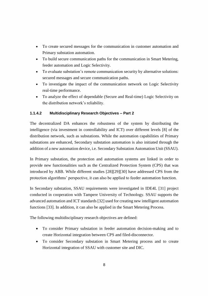
Local network in group of smart digital equipment within the customer premises is called Home Area Network (HAN). Smart devices use this network to interact with each other and other resources in order to facilitate home automation requirements. The most common devices in HAN are: controllable thermostats (heating and cooling loads), smart home appliances, local energy resources, PCs and smartphone, HEMS, and electric vehicle charging station. HEMS is central control unit that administers automation decisions in HAN. As can be seen in the Fig.1, HEMS also communicates with smart meter. This communication interconnects distributed energy resources to smart meter and presents abilities such as Demand-Side management and active distribution network management [6]. In addition, HEMS acts as a communication interface for data transmission to the next hierarchy information level which is aggregator software tool that locates between customer and electricity market. Aggregator is the centralized information integration that collects data of small-scale resources from multiple customers [7].

Figure 1. Home area network components

Both wired and wireless technologies are used in HAN.

While CAN, Ethernet, and HomePlug [8] are examples of

wired technologies; wireless technologies include wireless

LAN, Zigbee [9] and Z-wave [10].

B. Information Integration in Home Area Network

Energy demand management algorithms are implemented by HEMS in order to intelligently switch customer

consumption from electrical grid to local energy sources. Communication between HEMS and local energy resources is indispensable in order to check the availability of existing energy resources in customer premises. Fig.2 depicts an example of communication between HEMS and BMS.

Figure 2. Partial interaction diagram between HEMS and BMS

In the above figure, HEMS checks battery load requirement and then asks for the battery availability. Next, HEMS asks for the State of Charge (SoC%) in the battery and decides about duration of time that load can be supplied from the battery. Finally, battery starts supplying of the load. It is supposed that battery is available and has enough charge to cover the load energy requirement. Participants in HAN are equipped with different networking interfaces which are based on their operation, cost and processing power. As it was highlighted in the Fig.2, HEMS and BMS need to communicate and information integration is required if they include different communication interfaces.

C. Security in Home Area Network

State-of-the-art data network infrastructures in smart grid

propose interaction between customer domain and external

information systems. This communication provides

advantages such as remote meter reading and Demand-Side

Integration but on the other hand it presents security issues

like customer privacy limitation or unauthorized use of

customer properties [11]. The security issues in customer

domain can be divided to three categories: customer privacy,

customer property security and feel of security by customer

[12] .While the first category focuses on securing of customer

activity information, the second class of security concentrates

on protecting of customer resources and devices from

unauthorized attacker. The last group of security discusses

about preventing from dissatisfaction feeling of customer

about smart grid systems. Displeasure impression of end-user

can lead to unsuccessful implementation of the smart grid.

From security point of view, HEMS is the most vulnerable

element in HAN since it is the most accessible node by

attackers. Moreover, connecting HEMS to the Internet

enhances its vulnerability. As HEMS utilizes both wireless

and wired technologies for data communication, consequently

home area network can be subjected to either wireless attacks

or computer networking attacks. Traffic analysis and jamming

attacks are examples of wireless attacks. Computer

networking attacks include Eavesdropping, unauthorized

access to customer devices, Man-in-the-middle attack, and

Denial-of-service attack.

III. SECURE INTEGRATION OF HEMS TO BMS

As it was explained in the previous section, information

integration is desired to complete data transmission between HEMS and BMS that contain different communication interfaces. HEMS device in our research work is ThereGate by There Corporation. It is a programmable controller that includes CPU, WLAN router, Ethernet switch, GSM/GPRS/3G, and integrated home automation functionalities. ThereGate runs on an embedded Linux operating system and supports TCP/IP and Ethernet ports for both LAN and WAN networks. The BMS device, developed by European Batteries Corporation, manages battery operation and supports CANopen generic I/O profile 401 standard [5] and serial communication interface. CANopen is higher layer protocol for Controller Area Network (CAN) devices. The BMS is CANopen slave device which can be controlled by external CANopen master.

A. Information Integration Requirements

There are several alternatives for integration of the HEMS to BMS. CAN-Ethernet Bridge or CAN-TCP/IP Gateway is an example of devices which can be used for integration. These devices make information integration possible but they have limited support for communication security standards. Since this experiment investigates secure data communication between HEMS and BMS, it brings the idea of using a Personal Computer (PC) that gives us freedom to think about various security protocols such as SSL. HEMS device (ThereGate) also supports SSL and can connect to the Internet with different configuration.

Integration is carried out by using of the PC and USB-CAN converter that model Ethernet-CAN adapter. PCAN-USB device, produced by PEAK-System, acts as USB-CAN converter and enables connection of the HEMS device to the CAN network of BMS via a Universal Serial Bus (USB) port in the PC. The connection from HEMS to PC can be completed either wirelessly through WLAN or via Ethernet cable. Ethernet cable is selected in our experiment.

Figure 3. Information integration between HEMS and BMS

According to the Fig.2 in the previous section, ThereGate needs to ask BMS about the State of Charge (SoC%) of the battery. Fig.3 shows an integration solution that makes this communication possible.

BMS supports CANopen device profile 401 [5] and the implemented Process Data Objects (PDOs) to be transmitted/received are specified by PDO mapping in the Object Dictionary of the BMS. PDOs are applied for real-time transmission of battery data and have their own mapping parameter list. PDOs can be transmitted either by occurrence of an event (event-driven transmission) or by reception of CAN request messages such as SYNC message or Remote message. Remote message is chosen in our testing.

In regards to the BMS data sheet, the value of the State of Charge (SoC%) exists in the second Transmit Process Data Object (TPDO2) in the Object Dictionary of the BMS. The SoC data are sent to the caller (ThereGate) upon the correct remote message receives by the BMS. The communication object identifier (COB-ID) for remote message is calculated in the hexadecimal format: COB-ID = 0x280 + Node-ID.

The Node-ID is the address that is assigned to the BMS which is CANopen slave device. The node address “20” (hexadecimal equivalent is 0x14) is configured to the BMS by using terminal software tool via its serial interface. Consequently, the COB-ID of the remote message is equal to 0x294 (0x280+0x14). This is the message identifier section that should be incorporated in the CAN remote frame along with other required fields for the remote frame. BMS sends the SoC% to the ThereGate when the CAN remote frame contains the mentioned COB-ID receives by the BMS. This CAN remote message should send to the BMS by the CANopen master that is PCAN-USB device. PCAN-USB device supplies with CAN Application Programming Interface (API), PCAN-Basic API, which provides API functions for easy development of software with CAN support. One of the API functions in the PCAN-Basic API is sending remote message by identifying the COB-ID for the remote message, other parts of the CAN remote frame is calculated by the API.

Network socket programming and PCAN-Basic API are software solutions in order to complete the communication between HEMS (ThereGate) and BMS. Client application in ThereGate uses network socket to send the COB-ID of the CAN remote frame to the server application in the PC. The server application in PC uses PCAN-Basic API libraries and creates respective CAN remote frame and delivers that to the USB side of the PCAN-USB device through the USB port of the PC. Finally, PCAN-USB converts the received remote frame which is in USB data format to the CAN data format and sends that to the BMS via its serial side. The response to this CAN remote message is a CAN data frame contains the value for SoC% of the battery. This CAN data frame sends back from BMS to the ThereGate by travelling from the intermediate devices.

B. Securing Data Communication in the Integration Model

The integrity of data between HEMS and BMS is vital since incorrect data have impact not only to the customer energy management but also to the high level decision of the aggregator [7] for implementing Demand-Side Integration.

If the attacker is able to penetrate inside the HEMS, he finds access to the sensitive information which is transmitted between HEMS and BMS. Then, the attacker is capable of putting battery in nonfunctional state by sending unrelated CAN messages. If the attacker can make the battery of one customer inactive, the risk also exists for other customers and this may affects to the aggregator decision.

Encryption and authentication are applied in order to secure data communication against passive and active attacks such as eavesdropping (especially when HEMS and PC communicates wirelessly) and message alteration respectively. The applied security protocols provide customer property security [12] which is battery in this experiment. The software and hardware characteristics of the implemented model in our testing are depicted in the Fig.4.

Figure 4. Software and hardware charactristicts of the integration solution

The username/password-based mutual authentication over

SSL is applied in order to enhance the security of communication between client and server applications. SSL converts raw messages (COB-ID in our testing) to the unclear ciphertext and mutual authentication guarantees that just authorized HEMS can connect to the server application. In mutual authentication both client and server authenticate each other by the following steps:

- Client application in HEMS requests access to the protected server application in PC.

- Server presents its SSL certificate to the client.

- Client verifies the certificate of the server and if it is trusted certificate, server is authenticated by the client.

- Client sends its username/password to the server.

- Server verifies the client’s credentials and if verification is successful, client is also authenticated by the server.

- Client application in HEMS is granted access to the server application.

After successful mutual authentication, the calculated COB-ID (0x294) for CAN remote message sends from HEMS to the PC in encrypted format. Server receives the COB-ID and creates the related CAN remote message by the aid of programming libraries in the PCAN-Basic API. The CAN remote message conveys to the USB-CAN converter in the USB data format. Then, USB-CAN converter converts the USB data packet to the CAN remote frame and sends that to the BMS with CAN communication protocol. The response to

this message is SoC% which exists in the TPDO2 and sends back to the HEMS.

In the tested model, server application fulfills the majority of the tasks. The implemented logic in server application is depicted in the Fig.5. Server application developed in Java secure socket programming for the Windows operating system in the PC.

Start Server Application

Initialize PCAN-Basic API

Put BMS (CANopen slave) to the Operational State

Secure Socket Layer for Read/Write Data from/to

HEMS in Encrypted Format

Listen on the Specified Port

Send Data Field to HEMS

Any Request from HEMS?

Is it Authenticated

Client?

YES

Response to the Remote Request?

Extract Data Field (SoC%) of the Received CAN

Message

YES

NO

Login Failed

NO

Use API and Create CAN Remote Message for the

Received COB-ID from HEMS

YES

Send CAN Remote Message to the CAN-USB Converter

Ignore Message

NO

CAN Message is Received from CAN-USB Converter

Read the Message Content by Using PCAN-Basic API

Figure 5. The implemented logic in the server application

Server receives the CAN response message to the calculated CAN remote message via USB-CAN converter. Then, server application extracts the data field of the received message and sends that to the HEMS with secure socket layer protocol. The data field of the received CAN message contains eight bytes of data and its value is “0x5B00000000000000”. According to mapping parameters list in the object dictionary of the BMS CANopen slave, the SoC% of the battery is mapped to the first byte of the data field i.e. SoC% = 0x5B = 91%.

The client application in HEMS receives the data field of the received CAN frame and interprets the first byte of data field (SoC =91%) in order to make decision about the duration of time that loads can be supplied by the battery.

The SSL protocol provides confidentiality and integrity for the network socket connection. First, it applies Message Authentication Code (MAC) to the application data. Next, the obtained message is encrypted. Finally, SSL record header is added to the generated message and transmitted in a TCP segment [13].

In addition, further level of security is obtained for the system by applying physical security which is a segment of Defense-in-Depth security model [14]. Physical security

restricts physical access to HEMS and USB-CAN converter by locating HEMS and USB-CAN converter in the safe place with locking in order to avoid physical connection failure.

Table below illustrates Ethernet and CAN frames that are transmitted between HEMS and BMS in our testing.

TABLE I. TRANSMITTED ETHERNET AND CAN FRAMES IN THE INTEGRATION SOLUTION

IV. CONCLUSION

This paper presented secure information integration between home energy management system and battery management system. From device point of view, USB-CAN converter along with personal computer was used to perform integration. Software models included client-server model along with application programming interface for Controller Area Network protocol. Data communications were secured by applying secure socket layer protocol with username/password-based mutual authentication over secure socket layer.

Protecting of communication in home area network is recommended since customer domain is connected to the Internet and it is exposed to the information security threats. By applying the proposed secure integration solution, home energy management system and battery management system securely communicates to each other in order to accomplish customer energy management algorithms efficiently. Furthermore, this protection creates validity for the required data of Demand-Side Integration which are transmitted from customer domain to other domains of smart grid.

REFERENCES

[1] National Institute of Standards and Technology. NIST Framework and

Roadmap for Smart Grid Interoperability Standards, Release 2.0, February 2012 [Online]. Available: http://collaborate.nist.gov/twiki-

sggrid/bin/view/SmartGrid/IKBFramework

[2] M. Pipattanasomporn, M. Kuzlu, and S. Rahman, “An algorithm for intelligent home energy management and demand response analysis,"

IEEE Trans. Smart Grid, vol. 3, pp. 2166-2173, Dec. 2012.

[3] J. Li, J. Y. Chung, J. Xiao, J. W. Hong, and R. Boutaba, " On the

design and implementation of a home energy management system," in

Proc. 2011 IEEE Wireless and Pervasive Computing (ISWPC) Symposium., pp. 1-6.

[4] J. Han, C. S. Choi, W. K. Park, and I. Lee, " Green home energy

management system through comparison of energy usage between the same kinds of home appliances," in Proc. 2011 IEEE Consumer

Electronics (ISCE) Symposium., pp. 1-4.

[5] CiA Draft Standard 401, CANopen Device Profile for Generic I/O Modules, CAN in Automation. Version 3, Jun. 2008.

[6] H. Farhangi, "The path of the smart grid," IEEE Magazine. Power and

Energy, vol. 8, pp. 18-28, Jan-Feb. 2010. [7] A. Koto, S. Lu, T. Valavaara, A. Rautiainen, and S. Repo,

"Aggregation of small-scale active resources for smart grid

management," in Proc. 2011 IEEE PES Innovative Smart Grid Technologies (ISGT Europe) Conf., pp. 1-7.

[8] S. L. Clements, T. E. Carroll, and M. D. Hadley, "Home area networks

and the smart grid," Pacific Northwest National Laboratory, Richland, Washington, Apr. 2011.

[9] K. Gill, S. H. Yang, F. Yao, and X. Lu, “A zigbee-based home

automation system," IEEE Trans. Consumer Electronics, vol. 55, pp. 422-430, May. 2009.

[10] C. Gomez and J. Paradells. "Wireless home automation networks: a

survey of architectures and technologies," IEEE Communications Magazine, vol.48, pp. 92-101, Jun. 2010.

[11] H. Khurana, M. Hadley, N. Lu, and D. A. Frincke. "Smart-grid security

issues," IEEE Security & Privacy, vol. 8, pp. 81-85, Feb. 2010. [12] K. Paananen, J. Seppala, H. Koivisto and S. Repo, "Analysing security

issues for a smart grid demonstration environment," in Proc. 2013

CIRED Electricity Distribution Conf., paper 1300. [13] W. Stallings, Network Security Essentials: Applications and Standards,

Edition. 1. Prentice Hall, 2000, p. 209.

[14] P. Didier, F. Macias, J. Harstad, R. Antholine, S. A. Johnston, and et al., "Converged plantwide Ethernet (CPwE) design and implementation

guide," Cisco Systems and Rockwell Automation Corps., Tech. Rep.

OL-21226-01, ENET-TD001E-EN-P, Sep. 2011.

Publication 2

P. Jafary, M. Salmenperä, S. Repo and H. Koivisto, “OPC UA security for protectingsubstation and control center data communication in the distribution domain of the smartgrid”, In IEEE International Conference on Industrial Informatics (INDIN), Cambridge,United Kingdom, July 2015.

© 2015 IEEE. Reprinted, with permission, from the proceedings of IEEE InternationalConference on Industrial Informatics (INDIN).

OPC UA Security for Protecting Substation and Control Center Data Communication in the

Distribution Domain of the Smart Grid

Peyman Jafary, Sami Repo Department of Electrical Engineering Tampere University of Technology

Tampere, Finland [email protected], [email protected]

Mikko Salmenpera, Hannu Koivisto Department of Automation Science and Engineering

Tampere University of Technology Tampere, Finland

[email protected], [email protected]

Abstract— The distribution domain of the smart grid incorporates advantages of the newest substation automation standards in order to enhance distribution network automation. State-of-the-art distribution automation solutions use the public Internet for exchanging data between substation and control center. This presents challenges for cybersecurity, particularly for critical data determining distribution network operation. Therefore, Internet communication between substation and control center should be carried out via a secure communication protocol. OPC Unified Architecture (UA) is an interoperable communication standard supports Internet protocols from one hand and obtains benefits from mature built-in security mechanisms from other hand. This paper describes a solution for secure data transmission between modern substation and control center over the Internet. In this approach, circuit breaker position data is chosen as the data example that is defined in respect to the IEC 61850 data model and securely transmitted to OPC UA client application at remote control center by employing the OPC UA security architecture functions.

Keywords—distribution automation; IEC 61850; OPC UA security model; smart grid; substation automation

I. INTRODUCTION One of the major challenges in industrial control systems

and SCADA has been providing standard access to the automation data from devices of various manufacturers with different communication interfaces. The primary effort for solving this challenge was presenting OLE for Process Control (OPC) which is the standardized interface based on the Microsoft COM/DCOM technologies for exchanging real-time data in the client-server model [1]. The most recent OPC specification is OPC UA (OPen Connectivity Unified Architecture) [2] which was presented to overcome the limitations of classic OPC specifications, and provides a common object-oriented model for all OPC data in the secure way. Security is enhanced in the OPC UA specification (IEC 62541) by defining OPC UA security model that addresses security requirements [3].

In the distribution domain of the smart grid, high degree of distribution automation is enabled by integration of automation

applications at control center, modern substation automation systems and geographically dispersed devices [4]. Control center SCADA has data connections with applications inside and outside of the control center. Future SCADA software uses the IEC 61968 and IEC 61970 standards for communication with internal applications such as Distribution Management Systems (DMS) and Energy Management Systems (EMS). Additionally, SCADA remotely communicates with substations via the use of widespread communication protocols such as the IEC 60870-5-101/104, DNP3, and OPC UA.

OPC UA protocol runs over TCP/IP protocols, and provides secure cross-domain communication between OPC UA client and server over the Internet. These features make OPC UA a suitable candidate for communication in the smart grid and distribution network automation [5]. State-of-the-art substation automation systems support the IEC 61850 standard operating over the regular IT networking protocols. Consequently, connectivity between substation data network and control center network can be accomplished via standard IP-based networks. The latest distribution automation solutions use the Internet for data communication between substation LAN and control center network.

Internet provides flexible and cost effective communication solution for the smart grid. However, risks caused by network security threats are also increased. Therefore, securing exchanged data between substation and control center is mandatory. While using of Internet security protocols have been proposed [6] for data protection, applying application layer security protocols are also recommended to increase security of critical data transmission.

This study applies the OPC UA security methods in order to sign, encrypt and authenticate messages between modern substation communication gateway and OPC UA client at control center via the Internet. These messages encompass diverse information including the substation circuit breaker position data. In this experiment, the position data is used as a transmitted data example. The substation communication gateway has OPC DA server for IEC 61850, and receives position of Medium Voltage (MV) switch from protection relay referring to the IEC 61850 data model. Feeder protection relay

maps the IEC 61850 data to the Manufacturing Message Specification (MMS) protocol [7], and forward it to the communication gateway through the substation LAN. The aim is to study secure Internet connection between the substation gateway OPC DA server and remote OPC UA client. This is achieved by using the OPC UA wrapper application [2] that is OPC DA client from one side and OPC UA server from other side. The OPC DA client side is connected to the gateway OPC DA server and the OPC UA server side provides secure data connection for remote OPC UA client at control center.

The rest of this paper is structured as follows: substation automation in the distribution domain of the smart grid is explained in the section II. The section III discusses data protection in substation and control center communication. Next, section IV describes use case: secure transmission of circuit breaker position data from substation to control center. Finally, security analysis of the use case and conclusion are presented in the section V and section VI respectively.

II. SUBSTATION AUTOMATION IN THE DISTRIBUTION DOMAIN OF THE SMART GRID

The smart grid benefits from advanced automation technologies utilized to improve electrical network productivity and performance. Modern substation automation systems enhance substation operation efficiency and increase the automation level in the entire distribution network.

A. Automation in Legacy and Modern Substations Legacy substation automation systems are vendor

dependent with basic level of automation that is achieved through the use of traditional measurement devices and Fieldbus networks. As can be seen in the Fig. 1, relay in each feeder receives respective measurements from Current and Voltage Transformer (CT and VT) as the Analogue Signal via Hard Wiring (ASHW). Feeder relays exchange data via Fieldbus Hard Wiring (FBHW) that links relays together, and ends to the higher level Fieldbus interface within the substation [8]. The Fieldbus protocol depends on the relay manufacturer.

Fig. 1. Legacy substation automation systems

The Fieldbus interface presents feeders’ data to the station computer for local use and SCADA Remote Terminal Unit

(RTU) for remote usage. The RTU is connected to the industrial modem that transmits data to remote control center via dial-up connection or radio link.

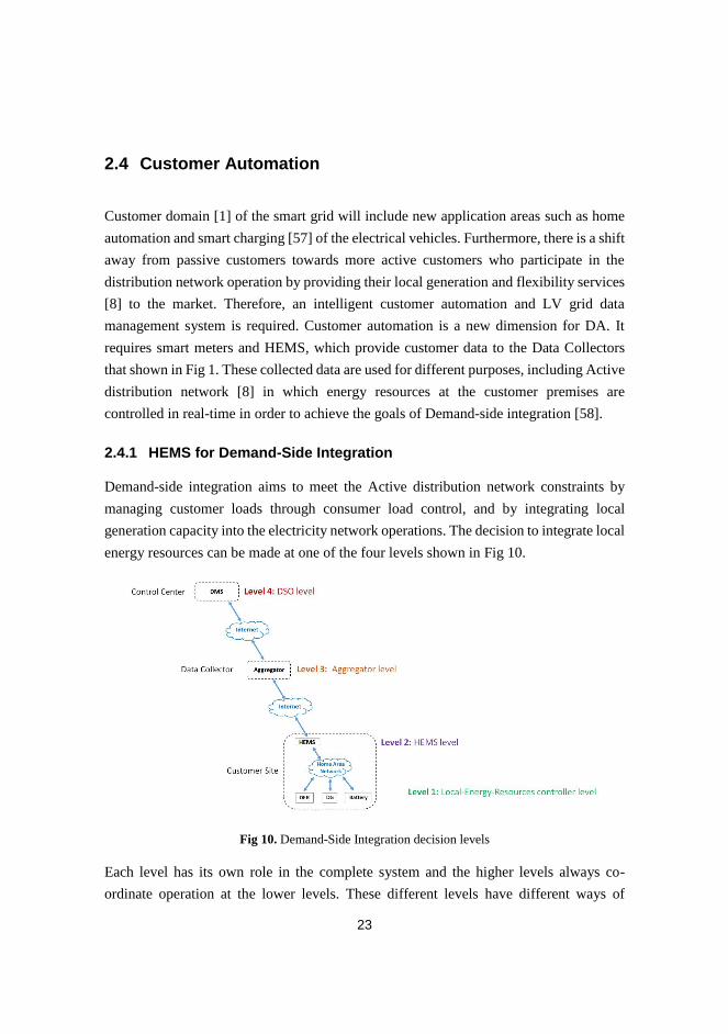
In modern substation automation, a single Ethernet-based data network (substation LAN) is used for data exchange among measurement, protection and control devices within the substation. The latest generation of substation protection and control devices are called Intelligent Electronic Devices (IEDs). They are programmable equipment supporting some level of intelligence along with advanced ICT protocols. In addition, State-of-the-art substation automation systems support the IEC 61850 standard. It is applied as a global communication model for substation automation systems regardless of the device/application manufacturer. Fig. 2 depicts the data network infrastructure in a modern substation.

Fig. 2. Modern substation automation structure

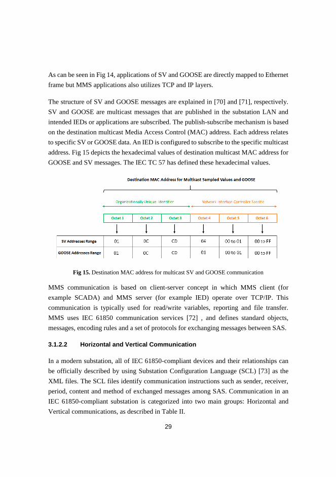
The IEC 61850 standard includes information models that describe substation automation devices and their functions in a hierarchical structure. In the IEC 61850 data structure [9], a substation automation device with its functions is hierarchically modelled as: Physical Device (PD), Logical Device (LD), Logical Node (LN), Data Object (DO) and Data Attribute (DA). The IEC 61850 modelled data are mapped to protocols such as GOOSE [7], Sampled Values (SV) [10] and MMS [7] in order to transmit both real-time and non-real-time data within the substation data network. Different levels are defined in the modern substation by respect to the location of devices and data communication.

B. Data Communication in Modern Substations As shown in the Fig.2, three levels are defined in the

modern substation network: Process level, Bay level, and Station level. The Process level includes modern measurement devices that publish measurement data to the process bus as the digital signals that are called Sampled Values. The Bay level contains IEDs that exchange data within the bay level, and also with control and automation devices at the Station level.

Communication between all the mentioned levels is carried out via the Ethernet-based network in accordance to the IEC 61850 standards. Communication in modern substation data network is classified into two categories: horizontal and vertical communication. The horizontal communication

address data exchange between IEDs in the bay level and the vertical communication is related to data transmission between the bay level and the station level devices.

In the modern substations, a communication gateway is used for data transmission between substation data network and control center. The communication gateway is a multi-functional device with more capabilities than a typical RTU. The gateway supports advanced electrical protection functions and substation automation standards including IEC 61850. It is also able to use Internet-based communication for data transmission between a modern substation and control center.

III. DATA PROTECTION IN SUBSTATION AND CONTROL CENTER COMMUNICATION

As it was mentioned, a modern substation applies the Internet as communication channel for data exchange between substation and control center. The Internet presents many advantages such as scalability, alternative transmission options, and worldwide remote access. However, transmitted data must be protected against cybersecurity threats as the Internet is a public network, and raw data can be accessed or modified by unauthorized attackers.

A. Communication Security Requirement Communication between substation and control center

contains diverse information such as measurement data, status of switches, control commands, acknowledgements, substation alarms and events. Some of these data are considered as critical information that directly affects to the operation of the substation critical devices and interlocking systems. If critical data are not protected, various security attacks such as the man-in-the-middle attack may happen in which the attacker is able to modify critical data. This is lead to physical harm to substation devices or undesirable function of control applications in control center. Therefore, critical data must be guarded against security threats in the public network. In other words, confidentiality, integrity and availability of the critical data must be assured.

Multiple competitive communication standards such as Modbus/TCP, IEC 60870-5-104, DNP3, and OPC UA can be used for Internet connection between substation and control center [11] [12]. OPC UA is considered as the preferable protocol candidate for exchanging data between substation and control center because it contains comprehensive inbuilt security functions that have been defined in OPC UA protocol specification [13]. Moreover, OPC UA can be applied along with the IEC 61850 standard. It provides a secure communication foundation between distributed applications of the smart grid [5].

B. OPC UA Security Model OPC UA security model manages security functions in

different layers: application layer, communication layer and transport layer. These security layers [13] cover essential data security objectives such as integrity, confidentiality,

availability, authorization and authentication. OPC UA itself is the OSI model application layer protocol and the mentioned security layers should be differentiated from the OSI model layers. The OPC UA security model is shown in the Fig. 3.

Fig. 3. OPC UA security model

As can be seen in the Fig. 3, the application layer provides user’s authentication and authorization via a logical connection between UA server and UA client that is called session. User authentication can be done by exchanging username/password, X.509 certificates or WS-Security token. The authorization for the authenticated user depends on the implementation of the UA server by each manufacturer.

The communication layer of the OPC UA security model offers confidentiality, integrity and application authentication. Real-time data are exchanged between client and server in a session in which data transmission are secured by establishing a secure channel. The communication layer applies encryption for confidentiality, digital signature for integrity and certain type of X.509v3 security certificate for application authentication [13].

System accessibility is enhanced by transmitting of secured data through the socket connection that applies error recovery techniques in the transport layer of the OPC UA security model.

IV. USE CASE:SECURE TRANSMISSION OF CIRCUIT BREAKER POSITION DATA FROM SUBSTATION TO CONTROL CENTER Control center contains different applications such as

SCADA, DMS, UA clients and servers. These applications receive data from substations in order to make decisions and send back commands to substations for network management in both normal and fault conditions. Integrity and accuracy of the transmitted data is necessary to maintain correct network operation.

In this experiment, the MV circuit breaker position data (open/close) is securely sent from substation to control center by applying IEC 61850-compliant devices and OPC UA protocol for Internet communication.

As can be seen in the Fig. 4, a single MV feeder is simulated in the Real Time Digital Simulator (RTDS)

hardware. The simulated MV feeder is externally controlled by a feeder protection IED that has data connection with the substation communication gateway. Both feeder IED and gateway are IEC 61850-compliant devices from ABB products: ABB REF615 [14] and ABB COM600 [15] respectively.

Fig. 4. Project device arrangement

RTDS includes a digital output that models the feeder circuit breaker position (open/close) as the binary signal (on/off) that is sent to the digital input terminal of the feeder IED. This binary signal should be defined for the feeder IED in the IEC 61850 format (IEC 61850 dataset). This dataset is transmitted to the communication gateway that sends the dataset to the OPC UA client application [16] via the Internet. This UA client can be considered as the OPC UA module of control center SCADA software. The aims are: first to define the circuit breaker position as the IEC 61850 dataset for communication within substation data network. Next, apply OPC UA and its security model to securely send the dataset to the external UA client via the Internet.

A. Circuit Breaker Position Data in the IEC 61850 Format The IEC 61850 dataset for the circuit breaker position is

defined by respect to the IEC 61850 hierarchy data model (PD.LD.LN.DO.DA) that was mentioned in the section II. The feeder IED includes the IEC 61850 configuration software tool for defining the dataset that is described in the table I.

TABLE I. DEFINE CIRCUIT BREAKER POSITION DATA IN THE IEC 61850

NO IEC 61850 Data Naming Description

1 PD The feeder IED hardware device (REF615)

2 LD

The IED includes multiple logical device functions such as protection, monitoring and control. The control function (CTRL) is selected.

3 LN

Every LD contains respective logical nodes. The logical device CTRL consists of several logical nodes. The logical node related to circuit breaker (CBXCBR1) is chosen.

4 DO Specific data objects are defined for the circuit breaker logical node. The position data object (pos) is elected.

5 DA

There are various data attributes for the position data object. The Boolean (on/off) data attribute (stVal) is selected as the DA. This Boolean attribute corresponds to the position data binary signal (open/close) that is entered to the feeder IED from RTDS.

The feeder IED configuration software (PCM600) [17] has IEC 61850 configuration tool. The IEC 61850 dataset (PD.LD.LN.DO.DA) for the circuit breaker position data is specified as the:

REF615.CTRL.CBXCBR1.pos.stVal

The PCM600 can be used for managing the feeder IED data communication in all the levels of the IEC 61850-compliant substation: Process level (measured Sampled Values to IED), Bay level (GOOSE messages communication between IEDs), and Station level (MMS communication between IED and the substation communication gateway).

In this experiment, the RTDS is considered as a device in the process level of a modern substation. The feeder IED and the substation communication gateway are located in the bay level and the station level respectively.

The feeder IED is configured to perform the vertical communication (from bay level to station level) that maps the defined dataset to the Manufacturing Message Specification (MMS) protocol, and transmits the dataset to the substation communication gateway. The substation gateway undertakes to transmit the received IEC 61850 dataset to the OPC UA client at control center.

B. Secure Transmission of the Dataset with OPC UA As it was depicted in the Fig. 4, the goal is to transmit data

between the substation communication gateway and control center by applying OPC UA standard via the Internet. The substation gateway includes configuration software (SAB600) that is utilized for IEC 61850 data communication and engineering to/from the substation gateway. First, MMS communication for the defined IEC 61850 dataset from the feeder IED to the substation gateway is configured in the SAB600. Next, the SAB600 is configured to apply the OPC standard for transmitting the defined 61850 dataset to the OPC UA client application at control center network.

The substation communication gateway supports IEC 61850 OPC Data Access (DA) server in which the circuit breaker position data is presented as an OPC item that is accessible for remote OPC DA clients. The main challenge here is to create connection between two incompatible communication protocol entities i.e. the substation gateway IEC 61850 OPC DA server and the control center OPC UA client.

The solution for enabling OPC UA client to connect the gateway IEC 61850 OPC DA server is using the OPC UA wrapper application [2]. The UA wrapper functions as both OPC DA client and OPC UA server that are connected to the substation gateway and control center client application respectively. The OPC UA client application from OPC Foundation [16] and the wrapper application developed by Unified Automation [18] are utilized in this experiment. Figure below displays the data communication steps from RTDS in the substation data network to the OPC UA client application in control center.

Fig. 5. Data communication steps from substation to control center

The OPC UA wrapper application runs on Microsoft Windows operating system. There are two possibilities for installing the UA wrapper application. It can be installed either on the substation communication gateway or in the external computer within the substation. In this case, the UA wrapper application is installed on the communication gateway because of compatibility and security reasons. The UA wrapper application is compatible with the substation gateway operating system that is embedded Microsoft Windows. In addition, the security is also enhanced because installing the wrapper application in the external computer requires the configuration of the external access to COM object (DCOM) over the network increasing potential attack surface on the gateway.

The substation gateway has two Ethernet ports: local and remote. It is connected to the feeder IED and other devices in the substation LAN through the local Ethernet port. Furthermore, the gateway is connected to the Internet via the remote Ethernet port. The installed wrapper application in the gateway presents the OPC UA communication between the gateway and the OPC UA client at control center. There are two types of data encoding are specified in OPC UA specifications: OPC UA native binary and XML. OPC UA binary protocol is selected for this experiment with UA TCP as the transport protocol.

In this way, OPC UA client is able to read the circuit breaker position data in the IEC 61850 data format. The OPC UA security protocols perform data protection functionalities that are described in the next section.

V. SECURITY ANALYSIS OF THE USE CASE The OPC UA security model creates secure data

communication between the OPC UA client and the wrapper. First, data availability is confirmed by creating socket connection. Second, security mode and security policy are applied for creating secure channel. The security mode is selected as the SignAndEncrypt in which transmitted messages are both signed and encrypted. The security policy is selected as the Basic128Rsa15 [19] in which security algorithms apply RSA15 for Key-Wrap-algorithm and 128-bit encryption. When the secure channel is established, the UA client and the UA wrapper applications are authenticated by exchanging certain X.509v3 certificates which are called Application Instance Certificates (AICs). Secure channel that is basically utilized for

deriving the symmetric keys which are applied for signing and encrypting of the subsequent messages.

Finally during the session establishment, UA client and wrapper exchange their Software Certificates (SCs) that identify the products and supported profiles [13]. In this experiment, user authentication is also performed during session establishment. The identity of the control center person that intends to connect the UA wrapper is proved by presenting user credential (username/password) to the wrapper. Fig. 6 depicts the data flow in secure connection establishment between UA client and UA wrapper.

Fig. 6. Secure connection establishment between UA client and UA wrapper

Secure connection establishment between the UA client and

UA wrapper is accomplished in four stages: endpoint discovery, secure channel creation, session creation and session activation [13]. Each stage includes specific OPC UA messages and security credentials which are described in the table II regarding to the Fig. 6.

TABLE II.MESSAGE DESCRIPTION IN SECURE CONNECTION ESTABLISHMENT BETWEEN UA CLIENT AND UA WRAPPER

OPC UA

Security Model

Stage Message Number Message Description Security

Credentials

Transport Layer

Com

munication Layer

Endpoint D

iscovery

1 UA client sends GetEndpoints Request to the wrapper in order to realize different UA server configuration.

Wrapper’s AIC 2 Wrapper sends GetEndpoints Response that includes the wrapper’s AIC. 3 Client asks from its validation authority in order to validate the received wrapper’s AIC. 4 The client validation authority responses that the received wrapper’s AIC is a trustworthy certificate.

Secure Channel

Creation

5

Client sends the OpenSecureChannel Request that includes the client’s AIC. This message is sent by respect to the chosen security policy and mode: the security policy is Basic128Rsa15 and the security mode is Sign and Encrypt. This security mode assures both integrity and confidentiality of the transmitted message by signing the message with private key of the client’s AIC, and encrypting the message with public key of the wrapper’s AIC. Wrapper’s AIC,

Client’s AIC 6 Wrapper asks from its validation authority about the validity of the received client’s AIC. 7 The wrapper validation authority is confirmed that the received client’s AIC is truthful.

8 The wrapper sends the OpenSecureChannel Response message which is secured with same security policy and mode i.e. signs the message with private key of the wrapper’s AIC, and encrypts the message with public key of the client’s AIC.

Application Layer

Session C

reation

9 Client sends CreateSession Request to the wrapper. This message is secured with the chosen security policy (Basic128Rsa15) and mode (Sign and Encrypt) but the derived keys during secure channel establishment are used for signing and encrypting the message. Derived Keys,

Wrapper’s SC

10 Wrapper replies by the CreateSession Response message. This message contains the wrappers’ SC. 11 Client asks its validation authority to validate the received wrappers’ SC.

12 The validation result is sent back to the client. The wrappers’ SC is considered as trustworthy certificate.

Session A

ctivation

13 The ActivateSession Request is sent to the wrapper. This message includes the client’s SC along with security credential (username/password) of the control center user.

Derived Keys, Client’s SC,

User/Password

14 The wrapper asks its validation authority to validate the received client’s SC. 15 The received client’s SC is validated as truthful.

16 Validity of the received security credential (username/password) is asked from the user management system of the substation gateway operating system that is Microsoft Windows.

17 The Windows user management system approves the user identity and sends back the validation result.

18 Wrapper sends the ActivateSession Response to the client, and secure connection between the wrapper and client is established.

There are two authentication mechanisms in the OPC UA security model: user authentication and application authentication. The user authentication is managed by creating a session which should be activated before using by presenting the user credential to the UA server (wrapper). Therefore, the user authentication in OPC UA consists of two steps: create session and activate session.

The other authentication mechanism is application authentication utilizing for creating secure communication channel in OPC UA security model. In OPC UA, an AIC is a unique security certificate for each UA application that is run on its respective device. This application instance certificate is used in order to identify the application and its related device while communicating to other distributed UA applications. All of the security certificates that are trusted by an application instance certificate are located in a special list which is called trust list. The Application authentication signifies that an OPC UA server/client checks the OPC UA client’s /server’s AIC and if the certificate is trustworthy, then AIC is authenticated and secure communication channel is established. Four authentication security categories are defined for UA applications [20]. Each category protects the system by

providing certain level of security and has its own application area. Table III describes four security tiers that can be configured to UA applications.

TABLE III. SECURITY TIERS IN OPC UA APPLICATIONS

NO Security Tiers Explanation

1 NO

Authentication

All valid certificates are trusted, and all OPC UA clients/servers are capable of communicating with the other parties. (No Security)

2 Server Authentication

All OPC UA clients trust a server. Clients are preconfigured by administrator to either put the certificate of server in the client’s trust list or place the Certificate Authority (CA) which issues certificate for the server in the client’s trust list.

3 Client Authentication

The OPC UA server just permits communication with trusted clients. Trust clients are who either have their certificates or the CA that issues certificate for them in the server’s trust list.

4 Mutual Authentication

Both OPC UA client and server should be preconfigured by the administrator, and communication will be performed only between trusted peers. (Maximum level of security)

The mutual authentication is applied in our testing because the UA client and the UA wrapper are communicating via the public network. Configuring the mutual authentication assures that only the permissible UA clients are able to communicate with the trustworthy UA server. The additional security level can be achieved by using the firewalls and VPN connection between the substation and control center. The network access to the substation data network and control center network is controlled by firewalls [21]. The VPN creates a secure private link (tunnel) between substation and control center networks over the public Internet.

Although the OPC UA security specification is comprehensive and broad, but utilizing a VPN is also recommended since OPC UA security implementation in various stacks may contains some implementation flaws. In fact, applying a VPN connection adds another layer of security for transmitted data between substation and control center. In this experiment, a Point to Point Tunneling Protocol (PPTP) VPN [22] was also utilized for increasing security by creating a secure tunnel between substation LAN and control center network over the Internet. As a result, authentication is performed via the Extensible Authentication Protocol (EAP) during VPN connection establishment between substation and control center. Besides, OPC UA data is encapsulated in the in the payload of the PPTP packets, and secured two times: one time with the security protocols of the OPC UA security model, and additionally compressed and encrypted by the PPTP VPN protocols.

VI. CONCLUSION

In this experiment, reliable and secure OPC UA communication was established with real devices in the laboratory. The OPC UA security architecture enhances Internet communication security by creating login session, secure channel and socket connection between UA client in control center and UA server in the substation communication gateway. The substation gateway also applies the IEC 61850 standard to interact with IEDs within the substation data network. Accordingly, secure remote communication of OPC UA clients with substation IEC 61850 devices is enabled via the substation communication gateway.

Internet data communication between control center and modern substations must be protected against cybersecurity attacks in order to assure correctness of the exchanged data. The integrity of the transmitted data results in reliable and secure distribution network automation that finally leads to the safe and efficient smart grid.

REFERENCES

[1] Y. Shimanuki, “OLE for process control (OPC) for new industrial automation systems,” Systems, Man, and Cybernetics 1999. IEEE SMC'99 Conference Proceedings. 1999 IEEE International Conference on, vol. 6, pp. 1048-1050. IEEE, 1999.

[2] T. Hannelius, M. Salmenpera, and S. Kuikka, "Roadmap to adopting OPC UA," Industrial Informatics 2008, INDIN 2008. 6th IEEE International Conference on, pp. 756-761. IEEE, 2008.

[3] H. Renjie, L. Feng, and P. Dongbo, “Research on OPC UA security,” Industrial Electronics and Applications (ICIEA), 2010 the 5th IEEE Conference on, pp. 1439-1444. IEEE, 2010

[4] J. Benoit, S. Gagnon, and L. Tétreault, “Securing Distribution Automation,” Western Power Delivery Automation Conference, Washington. 2010.

[5] S. Lehnhoff, W. Mahnke, S. Rohjans, and M. Uslar, “IEC 61850 based OPC UA Communication-The Future of Smart Grid Automation,” 17th Power Systems Computation Conference (PSCC 2011), Stockholm.

[6] V.C Gungor, and F. C Lambert, "A survey on communication networks for electric system automation," Computer Networks 50, 2006.

[7] IEC 61850 standard , part 8-1, Communication networks and systems in substations, “Specific Communication Service Mapping (SCSM)-Mapping to MMS and to ISO/IEC 8802-3”, First edittion, 2004-05

[8] J. Ekanayake, K. Liyanage, J. Wu, A. Yokoyama, and N. Jenkins, “Smart grid: technology and applications,” First edition, WILEY, 2012

[9] IEC 61850 standard, part 7-1, Communication networks and systems in substations, “Basic communication structure for substation and feeder equipment-Principles and models”, First edittion, 2003-07

[10] IEC 61850 standard, part 9-2, Communication networks and systems in substations, “Specific Communication Service Mapping (SCSM) - Sampled values over ISO/IEC 8802-3”, First edittion, 2004-04

[11] G. Sanchez, I. Gomez, J. Luque, J. Benjumea, and O. Rivera. “Using internet protocols to implement iec 60870-5 telecontrol functions,” IEEE Transactions on Power Delivery, vol. 25, pp. 407-416, IEEE 2010

[12] X. Lu, Z. Lu, W. Wang, and J. Ma. “On network performance evaluation toward the smart grid: A case study of DNP3 over TCP/IP,” GLOBECOM 2011, IEEE Global Telecommunications Conference, pp. 1-6, IEEE 2011.

[13] W. Mahnke, S. Leitner, and M. Damm, "OPC Unified Architecture," First edition, Springer, 2009

[14] http://new.abb.com/medium-voltage/distribution-automation/numerical-relays/feeder-protection-and-control/relion-for-medium-voltage/feeder-protection-and-control-ref615-iec

[15] http://new.abb.com/mediumvoltage/distributionautomation/communication-devices/gateways-and-controllers/grid-automation-controller-com600

[16] https://opcfoundation.org/developer-tools/developer-kits-unified-architecture/sample-applications

[17] http://new.abb.com/mediumvoltage/distributionautomation/engineering-tools/protection-and-control-ied-manager-pcm600

[18] http://www.unified-automation.com/products/wrapper-and-proxy.html [19] http://opcfoundationonlineapplications.org/profilereporting/index.htm?

ModifyProfile.aspx?ProfileID=53605a50-a6ac-44ed-9baa-36c4873ff504 [20] R. Armstrong and P.Hunkar, “The OPC UA security model for

administrators,” white paper, version 2, 2010 [21] D. Anderson and N. Kipp, “Implementing firewalls for modern

substation cybersecurity,” Schweitzer Engineering Laboratories Inc. 2010

[22] https://tools.ietf.org/html/rfc2637

Publication 3

P. Jafary, S. Repo and H. Koivisto, “Secure communication of smart metering data in the smartgrid secondary substation”, In IEEE Innovative Smart Grid Technologies - Asia (ISGT ASIA),Bangkok, Thailand, November 2015.

© 2015 IEEE. Reprinted, with permission, from the proceedings of In IEEE InnovativeSmart Grid Technologies - Asia (ISGT ASIA)

Secure Communication of Smart Metering Data in the Smart Grid Secondary Substation

Peyman Jafary, Sami Repo Department of Electrical Engineering Tampere University of Technology

Tampere, Finland [email protected], [email protected]

Hannu Koivisto Department of Automation Science and Engineering

Tampere University of Technology Tampere, Finland

[email protected]

Abstract— Smart Metering is considered as a critical infrastructure that collects low voltage network data for billing, management and automation applications in the smart grid. Secondary substation also plays significant role in the future smart grid and can participate in Smart Metering process. Reliable smart grid operation requires authentic metering data. Thus, Smart Metering data communication in Secondary substation must be protected against cyber-security attacks. This paper discusses Smart Metering architecture and security requirements, and then proposes utilization of the Secondary substation automation device for secure transmission of metering data from customer site to distribution network control center. The Secondary substation automation device provides security for communicating to customer site and control center via DLMS/COSEM security mechanisms and tunneled IEC 60870-5-104 data in PPTP VPN, respectively. Accordingly, customer metering data is securely transmitted to higher level information systems of the utility company via Secondary substation.

Keywords—DLMS/COSEM; IEC 60870-5-104; secondary substation automation; smart grid; smart metering security

I. INTRODUCTION Traditionally, the distribution network management was

only based on Medium Voltage (MV) data without any focus on Low Voltage (LV) network data. In the smart grid distribution network, role of the LV network data becomes more important because of emerging new application areas such as Distributed Generation (DG), Renewable Energy Resources (RES) and customer automation. These new topics lead to the new network management model that is called Active Network Management (ANM) [1] in which LV network data is used for dynamic administration of the DG in the distribution network. In addition, LV network data is applied in Advanced Distribution Automation (ADA) applications at control center. ADA utilizes LV data as a new dimension for distribution automation resulting in remote monitoring and management of LV grid from control center [2].

LV network data is collected by applying advanced and intelligent metering systems. In order to implement effective ANM and ADA, collected LV data by metering systems must be trustworthy and protected against security attacks during transmission from LV network to upper levels of the distribution network. Several studies have been investigated cyber-security issues of intelligent metering and proposed security solutions [3],[4],[5].

The intelligent metering elements are distributed in different locations of the distribution network. One location could be Secondary substation that is utilized to transmit metering data to control center via SCADA communication protocols. This communication must be secured by implementing network and SCADA security techniques [6],[7].

This study considers Secondary Substation (SS) in Smart Metering procedure in which SS communicates with both smart meter and SCADA via DLMS/COSEM and IEC 60870-5-104, respectively. While DLMS communication is secured with internal security functions of the protocol, PPTP VPN [8] is used to protect IEC 60870-5-104 Internet communication. This paper is organized as follows: Section II explains smart metering architecture and security. Next, smart grid secondary substation and security is discussed in Section III. After this, secure communication of low voltage data is described in Section IV. Finally, conclusion is presented in Section V.

II. SMART METERING ARCHITECTURE AND SECURITY The term Smart Metering implies a system that automatically measures, records, analyzes and controls customers’ energy consumption with the aid of advanced measurement protocols and bidirectional communication technologies [9]. Smart Metering includes three main sections: Automated Meter Reading (AMR), Advanced Metering Infrastructure (AMI) and Automated Meter Management (AMM). Information security mechanisms are necessary in all the sections in order to operate reliable Smart Metering.

A. Smart Metering Architecture in Distribution Network Smart Metering employs two-way communication between

customer sites and control center. In Smart Metering, Home Energy Management System (HEMS) and Distribution Management System (DMS) are automation elements at customer premises and control center respectively.

Figure 1: Smart Metering architecture in the distribution network

As can be seen in Fig. 1, data communication is bidirectional between all entities in the Smart Metering architecture. In customer site, smart meter exchanges data with HEMS from one side and with Neighborhood Area Network (NAN) [10] from other side. The HEMS is considered as the customer gateway that manages automation decisions [11] among smart equipment in the Home Area Network (HAN). Data from several smart meters is transmitted to the Meter Data Concentrator (MDC) via NAN.

Collected data in MDC is sent to the control center databases through Wide Area Network (WAN). In the control center, received data by Gateway is delivered to metering databases that are used for ANM and ADA applications. In fact, metering database is not just used for customer billing system. Additionally, metering database integrates to DMS and SCADA in order to provide new functions such as automatic demand response, integration of DERs to distribution network, and LV network monitoring and fault management.

B. Smart Metering Data for ANM and ADA Smart meters are used not only for remote reading of

customers’ monthly consumption but also for transmitting LV network data (customer data) that is used for ANM and ADA. From ANM point of view, smart meters send LV power quality data first to MDC and subsequently to the metering database at control center. The ANM service (that could be a module in DMS) receives data from several MDCs as well as Distributed Energy Resources (DERs) data from the Aggregator [1] service. Then, the ANM service computes algorithms for Demand Side Management, power quality measurement and use of controllable energy resources.

Smart Metering also provides customer automation data for ADA. Customer automation is considered as a new dimension for modern distribution automation in which smart meters are able to indicate different LV network faults such as neutral conductor fault, blown fuse, over/under voltage and wrong

phase order [2]. In fault condition, the message is sent to the metering database that makes DMS capable of automatic monitoring and disconnection of the faulty customer from LV network via the smart meter.

Therefore, Smart Metering data is utilized for multiple purposes in ANM and ADA. Authenticity of this data is very important for genuine functioning of the distribution network. Hence, Security requirements must be considered in communication protocol implementation, data exchange method and network design.

C. Smart Metering Security Requirements Smart Metering communication starts from smart meter

acting as an interface between customer data network and distribution data network. While data exchange in NAN is mostly carried out via metering communication standards, TCP/IP-based protocols are used in WAN communication. Secure Smart Metering communication provides valid data that result in dependable distribution network management and automation. In Fig. 1, different sections of Smart Metering have their own security issues and possible security threats.

Although IT security protocols can be applied for securing some parts of Smart Metering architecture, but exclusive security demands are also required in order to protect whole system [3]. In AMR, secure communication protocol must be used to ensure controlled access to meters as well as customers privacy protection. The AMI should be designed by considering network security technologies protecting AMI against cyber-attacks. Moreover, all collected data must be inspected before delivering to the AMM system that manages end-users data in protected databases.

Generally, the most important security aspects of Smart Metering are Confidentiality, Integrity, Availability and Accountability. Table I describes Smart Metering security requirements by taking the mentioned aspects into account [3].

TABLE I. SECURITY REQUIREMENTS OF SMART METERING IN THE DISTRIBUTION NETWORK

Smart Metering Security Requirements

AMR

and

AMI

Confidentiality Privacy for transmitted data/commands in NAN and WAN. Privacy for customer data stored in MDC.

Integrity Exchanging of data/commands must only be limited to authenticated smart meters and legitimate MDC. Protection of transmitted data/commands in NAN and WAN against unauthorized access and modification. Unauthorized local and remote access to the MDC and smart meter must not be allowed.

Availability Availability of smart meter internal firmware and communication interface. Reliable data transmission in NAN and WAN. Availability for stored data in MDC.

Accountability Any change to the smart meter setting must be auditable. Data exchange of MDC with other applications should be accountable.

AMM

Confidentiality Customer privacy protection by keeping all the databases private.

Integrity

Access control for any local user/application/device/network connection accessing to the databases. Unauthorized network access to the AMM local network must be blocked. Access control for any remote user/application/device/network connection accessing to the databases. Authentication of MDC to the control center Gateway before exchanging data/commands.

Availability High database availability technologies for metering critical data.

Accountability All data transaction from metering databases to other applications should be recordable.

D. Smart Metering Security Solutions There are various security solutions addressing the

mentioned security requirements in Table I. Security solutions should be selected based on the devices capabilities, network media (wired or wireless), application requirements and cost.

Data confidentiality can be achieved by applying encryption algorithm that protects Smart Metering data communication against eavesdropping and traffic analysis. Ideally, communication protocols with built-in security functions should be selected for data communication. While the link layer encryption is used in NAN, encryption at the network layer, for example IPSec, is applied in WAN.

Data integrity is assured by using authentication techniques such as password authentication or public-key cryptography protecting Smart Metering communication against active security attacks including data alteration [12]. In NAN, each smart meter can be distinguished by a digital certificate that authenticates the smart meter to the authentication server that may place in the MDC location. In WAN, Secure Socket Layer (SSL) protocol and VPN could be used for securing data communication over Internet Protocol (IP). In the AMM network, access to databases is protected by password authentication and role-based access control.

Data availability in smart meter can be obtained by designing the firmware with diagnostic tool that automatically checks the smart meter communication interface and alarms for any error. In NAN, a reliable network design that meets timing requirement and resist against traffic overloads results in availability. Data availability of MDC can be enhanced by creating backup for the stored data, and input power redundancy for MDC. Redundant network connection (for example dual sim card in mobile network) and TCP/IP socket connection increase data availability in WAN communication. In control center LAN, network redundancy techniques such as ring topology along with the Spanning Tree Protocol (IEEE 802.1D) improve data availability. Furthermore, redundant databases can be used for high critical data.

Accountability solution includes timestamp information for control commands, received data to MDC and stored data in metering databases. Moreover, MDC and metering databases should audit logs in which all of the main data transactions with other applications are recorded.

A firewall and antivirus software also increase security by protecting the local networks in MDC location and control center from unauthorized network access and computer viruses. Furthermore, there are two other factors that affect Smart Metering communication security and should be regarded: HEMS security and physical security.

III. SMART GRID SECONDARY SUBSTATION AND SECURITY Secondary Substation (SS) is the last stage in the process of

delivering electrical energy from generation to end-users. Conventional SS mainly contains MV/LV transformer and fuses for protecting LV feeders without any automation functions. However, SS automation becomes more important in the smart grid and makes the SS capable of data communication with other parts of the distribution network.

SS automation is achieved by applying programmable intelligent device that support automation and networking standards. This device, also known as Automation Unit (AU), provides intelligent functions from one hand and interaction of SS with the control center from other hand. Research projects such as INTEGRIS [13] and IDE4L [14] investigate requirements for designing the AU in the SS. First, AU should be cost-effective for applying in SS. Second, automation protocols for LV network management and monitoring should be supported by AU. Finally, AU should be capable of the Internet communication in order to exchange data with the control center over the utility Internet.

Implementing SS automation functions like real-time LV grid management require LV network data that is provided via Smart Metering. Therefore, some tasks of Smart Metering can be performed in SS. MDC location (in Fig.1) and SS are closest places to customer premises. Accordingly, MDC can operate as a part of AU in SS. Integration of MDC to AU adds database functionality to AU. The stored data in AU database can be used either locally (at secondary substation) or remotely (at control center) for ANM and ADA applications.

Incorporating SS automation in distribution network management and automation increases consistency in the whole distribution network. New approaches in distribution network administration propose distributed intelligence model [1] by shifting simple intelligent functions of ANM/ADA from control center to AUs at SSs. From Smart Metering data storage point of view, this means changing from centralized AMM databases at control center to the distributed databases at SSs. In other words, all of LV network data values are not sent from MDC to AMM and only messages contain calculated values are reported instead. The distributed intelligence model is more reliable since AMM databases are not the bottleneck of Smart Metering system for ANM/ADA decisions, and some of these decisions are autonomously made at SSs.

From information security point of view, local and network (Internet) access to AU must be controlled. Exchanging data with AU database must be restricted to authenticated customers (smart meters) and authorized applications at control center. Furthermore, appropriate access right (read/write) should be defined for the stored data in AU database.

IV. SECURE COMMUNICATION OF LOW VOLTAGE DATA Regarding to the prior section, SS can be applied as the

place for concentrating LV measurement data in Smart Metering. This becomes feasible by attaching MDC function to the AU. Thus, the AU should support both metering protocols and TCP/IP protocol for data communication in NAN and WAN respectively. The most common metering protocols in NAN are IEC 62056 DLMS/COSEM, IEC 61334 PLC and EN 13757 M-Bus. The Internet communication in WAN can be accomplished by SCADA communication protocols such as IEC 60870-5-104, DNP3, Modbus/TCP and. In the following, transmitting voltage data from smart meter to the monitoring application is carried out with real devices and applications.

A. Lab Setup Description Smart Metering process is partly experimented by using the

smart meter, SS supervision device and IEC 60870-5-104 (IEC

104) simulator. Smart meter measures customer voltage value and sends that to SS supervision device via DLMS protocol. Then, the SS supervision device (acts as AU with MDC function) transmits voltage value to the IEC 104 simulator via the Internet. This simulator can be considered as the control center SCADA. Fig. 2 shows devices layout and corresponded place in accordance with Smart Metering architecture.

Figure 2. Lab setup Devices

In Fig. 2, smart meter offers DLMS/COSEM server for measurement data. The SS supervision device supports both DLMS/COSEM client and IEC 104 Controlled station that are connected to smart meter and IEC 104 simulator (IEC 104 Controlling station), respectively.

DLMS communication is performed via RS-485 serial connection that models NAN communication, and IEC 104 communication is carried out via the Internet that is considered as the WAN. Both smart meter (E650) and SS supervision devices (S760) are from Landis+Gyr [15]. The IEC 104 simulator is the software tool from Mitra software [16].

B. Security vulnarabilities in the Lab Setup There are several security vulnerabilities in the lab setup

before configuring security parameters. All the exchanged data/commands are transmitted as the plaintext in both NAN and WAN communication. This may expose transmitted data/commands to security attacks, particularly in WAN i.e. Internet communication. Moreover, smart meter and MDC are not authenticated each other. In WAN, unauthorized IEC 104 clients in the Internet can connect to MDC and send unrelated control commands to the smart meter.

In order to secure the lab setup, all the communication parties must be authenticated and exchanged data/commands must be confidential. DLMS/COSEM protocol includes security functions that can be applied for securing NAN communication but IEC 104 protocol has no built-in security mechanisms to create secure WAN communication. However, computer network security protocols can be used for protecting WAN communication of IEC 104 messages.

C. Security in DLMS/COSEM Protocol Device Language Message specification (DLMS) is a

general notion for abstract modeling of communication parties. COmpanion Specification for Energy Metering (COSEM) specifies collection of objects as the common language for metering data on top of DLMS. The combination is the IEC 62056 DLMS/COSEM that provides modeling, messaging and transporting of exchanged data between metering devices in the client-server architecture [17]. First, metering data and functions are modeled in the COSEM data model. Next, the

modeled data is mapped to the Application Protocol Data Unit (APDU) and DLMS message is created. Finally, the produced message is transported by either High-Level Data Link Control (HDLC) or TCP (UDP) in serial communication or IP-based network, respectively.

In a DLMS/COSEM server, all the metering data and functions are structured using object modeling in which every quantity can be identified as a unique code in the OBject Identification System i.e. OBIS. OBIS code is meaningful sequence of six numbers in hierarchical structure, which is manufacturer-independent. Moreover, objects in COSEM data model can be organized in different manners and form Logical Devices (LDs). One physical device may include several LDs.

Information security in DLMS/COSEM protocol can be classified into four main categories: role-based access security, peer authentication, transport security and security logs.

In the first category, read and write access to COSEM data model elements (methods and attributes) is assigned to the clients based on their roles. Before accessing the LD in a server, clients require establishing an Application Association (AA) in order to identify the application context. Role-based security access to LDs can be defined in the server based on the established AA by the client. In other words, security policy is defined with respect to the AA. Role-based access security is carried out in two stages: first, visibility of server LDs to the clients is based on the established AA. When permissible LD becomes visible to the client, the second step is to define access right (read/write) for attributes and methods in the visible LD.

The second category is peer authentication that includes three [18] authentication levels: No Security (NS), Low Level Security (LLS) and High Level Security (HLS). NS is for public access without authentication. The LLS is unilateral password authentication in which the DLMS client must send password to the DLMS server. In HLS, mutual authentication is accomplished by exchanging security challenges between client and server i.e. challenge-response authentication. Both LLS and HLS take place during AA establishment and the AA is established only if authentication is successful.

The third security category is transport message security that happens after successful authentication and AA establishment. In this stage, COSEM data is mapped from data model to APDU in order to create DLMS/COSEM message for transmission. The payload (COSEM data) of this message can be either non-protected or protected by cryptographic algorithms in three ways: authenticated, encrypted and authenticated encryption. The Security Header (SH) is added to the protected messages and determines security policy of the message. Fig. 3 shows structure of a secured APDU by the authenticated encryption policy.

Figure 3. Secured APDU with Authenticated Encryption policy

DLMS/COSEM uses the symmetric cryptography suite for authentication and encryption algorithms: Galois Counter Mode (GCM) with AES-128. The AES-GCM-128 is utilized for both encrypting/decrypting APDU content and generating Authentication Tag (AT) that is appended to the end of the secured APDU. The AES-GCM-128 operation includes two actions: Authenticated Encryption (AE) and Authenticated Decryption (AD) [19]. The AE is performed by obtaining four inputs: secret key for encryption, initialization vector, plain text and additional authenticated data (this value is authenticated but not encrypted). The AD module first performs authentication and then generates plain text by receiving secret key for decryption, initialization vector, cipher text, additional authenticated data and further the Authentication Tag (AT) that is appended to the end of secured APDU.

The fourth security category is reporting AA events that provide accountability via security events logs. Any attempt for AA establishment (accepted/refused/unsuccessful) should be logged with timestamp.

D. Security in IEC 104Protocol The IEC 60870-5 standard describes communication

protocols for transmission of data and control commands in power system SCADA. The initial version of this standard is IEC 60870-5-101 (IEC 101) that discusses asynchronous data transmission over serial link. The last version is IEC 104 with same application layer as IEC 101but for communication over TCP/IP. IEC 104 contains object data modeling in which all required application data for power system SCADA are grouped in four main types of the information objects: Process, System, Parameter and File transfer information objects [20].

The IEC 104 APDU consists of two parts: Application Protocol Control Information (APCI) and Application Service Data Unit (ASDU). APCI contains control information for managing communication flow. Application data related to the above-mentioned information objects are carried inside ASDU in which every data element is uniquely addressed by Information Object Address (IOA) [20].

Figure 4. IEC 60870-5-104 APDU structure

In Fig. 4, all APDU sections including data payload (P) is transmitted as the plaintext without any security assignments. Consequently, this is not a safe protocol for public WAN communication i.e. Internet. However, IT security protocols, for instance VPN, can be used to improve security because IEC 104 APDUs are transported over TCP/IP networks.

E. Security Solutions for the Lab Setup First all of the devices should be configured. Smart meter

configures to run DLMS/COSEM server on RS485 interface and the physical HDLC device address is identified. Then, the Data Collection AA is defined.

The SS supervision device is configured to function as DLMS/COSEM client and IEC 104 controlled station. DLMS client is configured to request line voltage (OBIS: 1.1.32.7.0.255) from smart meter via serial port. Then, the voltage value is internally mapped to the IEC 104 data model.

The IEC 104 simulator is configured to operate as IEC 104 Controlling station for connecting to the SS supervision device, and request the mapped voltage value.

Security in DLMS communication is achieved via role-based access security and LLS authentication. The configured Data Collection AA only allows readout measurement data, and client application is not able to change (write) smart meter configuration. Furthermore, LLS authentication is configured for peer authentication. After successful authentication of the DLMS/COSEM client, Data Collection AA is established in which client is allowed to only to see measurement objects (including voltage value) with read data access right. There is no ciphering (message security) option for LLS authentication in the current version of the configuration software. As a result, client application is authenticated but messages are transmitted as the clear text in our experiment. However, in practice these messages must be sent as the cipher text.

Security in IEC 104 communication is assured via VPN connection. As it was explained earlier, IEC 104 messages are exchanged as the clear text and they require to be secured for Internet connection. In this experiment, we utilize Point to Point Tunneling Protocol (PPTP) [8] VPN for protecting IEC 104 Internet communication. Therefore, control center network must be first authenticated to the PPTP server at the SS network by sending username/password. After successful authentication, VPN connection is created and IEC 104 messages are wrapped within the VPN tunnel.

PPTP VPN applies Point-to-Point Protocol (PPP) [21] connections for transporting data between PPTP client at the control center and PPTP server at SS. PPTP VPN also uses Generic Routing Encapsulation (GRE) protocol that tunnels IEC 104 messages by incorporating them within PPP frames and encrypting PPP payloads i.e. IEC 104 messages. The PPP header and GRE header are added to the encrypted payload. These headers contain control data and tunnel information. Finally, the produced data frame is encapsulated within IP packet that includes new IP header. New IP header contains the IP addresses of PPTP client and PPTP server computers. In this way, all IEC 104 messages are encrypted and transmitted in a tunnel over the Internet.

Furthermore, firewalls are applied to protect control center and SS networks. All the incoming traffic is inspected by firewalls and any unauthorized network traffic is blocked. The SS firewall is configured to only allow PPTP VPN traffic (TCP port number 1723). So, all other Internet traffics are blocked and unknown IEC 104 Controlling stations are not allowed connecting to the SS supervision device via the Internet.

The above-mentioned security mechanisms were applied in order to fulfill the described requirements of the Table I for the lab setup. Figure below illustrates system components with explanations and general structure of the exchanged messages.

Figure 5. Explanation of Security solutions for the lab setup

V. CONCLUSION

This paper discussed secure LV data communication from customer place to monitoring application at control center via the SS automation device. This communication is accomplished in two main steps. First step includes voltage data communication from DLMS/COSEM server in smart meter to DLMS/COSEM client in the SS automation device. This communication is secured via the use of DLMS/COSEM protocol security functions. In the SS automation device, voltage value is mapped to IEC 104 and second step is started by integrating IEC 104 Controlled station into the remote IEC 104 monitoring software. PPTP VPN protects this Internet communication by encrypting IEC 104 messages.

Smart Metering is necessary for efficient collecting of data from LV network and delivering to utility information system. Security is an important parameter in Smart Metering communication that must be taken into account in the design, implementation and operation phases. Secure Smart Metering results in trusty distribution network management and automation.

REFERENCES

[1] S. Repo, F.Ponci, and D.D Giustina. "Holistic view of active distribution network and evolution of distribution automation," in 2014 Innovative Smart Grid Technologies Conference Europe., pp. 1-6

[2] P. Järventausta and et al. "Using advanced AMR system in low voltage distribution network management," in 2007 Proceedings of the 19th International Conference on Electricity Distribution., Paper, no. 0560.

[3] F.M. Cleveland "Cyber security issues for advanced metering infrasttructure," in 2008 IEEE Power and Energy Society General Meeting Conf., pp. 1-5.

[4] P. Savolainen, P. Koponen, S. Noponen, J. Sarsama and P. Ahonen. "Cyber security of smart metering of electricity consumption in Finland," in 2014 Nordic Electricity Distribution and Management Conference., paper 9.1.

[5] A. A Cardenas and et al. "A framework for evaluating intrusion detection architectures in advanced metering infrastructures," in 2014 IEEE Transactions on Smart Grid, pp. 906-915.

[6] V.C Gungor and F.C Lambert, "A survey on communication networks for electric system automation," Computer Networks Vol.50, May 2006.

[7] Y. Yang, K. McLaughlin, S. Sezer, Y.B. Yuan and W. Huang. "Stateful intrusion detection for IEC 60870-5-104 SCADA security." in 2014 IEEE PES General Meeting Conf., pp. 1-5.

[8] Point-to-Point Tunneling Protocol. https://tools.ietf.org/html/rfc2637 [9] J. Ekanayake, K. Liyanage, J. Wu, A. Yokoyama, and N. Jenkins, Smart

grid: technology and applications, First edition, WILEY, 2012 [10] W. Meng, R. Ma and H.H. Chen. “Smart grid neighborhood area

networks: a survey,”in 2014 IEEE Network, vol.28, issue 1, pp. 24-32. [11] P. Jafary, S. Repo and H. Koivisto. “Secure integration of the Home

Energy Management System to the battery management system in the customer domain of the smart grid,” in 2014 IEEE PES General Meeting Conference & Exposition., pp. 1-5.

[12] W. Stallings, “Network Security Essentials: Applications and Standards”, Edition. 1. Prentice Hall, 2000,

[13] INTEGRIS project. Available: http://www.fp7integris.eu [14] IDE4L project. Available: http://ide4l.eu/ [15] E650 smart meter, S760 supervision device. http://www.landisgyr.com/ [16] IEC 870-5-104 Simulator. http://mitraware.com/ [17] DLMS documentation. http://dlms.com/documents/Excerpt_BB12.pdf [18] DLMS documentation. http://dlms.com/documents/Excerpt_GB8.pdf [19] H. Dantas, “Vulnerability Analysis of Smart Meters” Master thesis, TU

Delft, Delft University of Technology, 2014. [20] G. Clarke, D. Reynders and E. Wright, “Practical Modern SCADA

Protocols: DNP3, 60870.5 and Related Systems”, First edition, 2004 [21] Point-to-Point Protocol. http://tools.ietf.org/html/rfc1661

Publication 4

P. Jafary, S. Repo and H. Koivisto, “Security solutions for smart grid feeder automation datacommunication”, In IEEE International Conference on Industrial Technology (ICIT), Taipei,Taiwan, March 2016.

© 2016 IEEE. Reprinted, with permission, from the proceedings of In IEEE InternationalConference on Industrial Technology (ICIT)

Security Solutions for Smart Grid Feeder Automation Data Communication

Peyman Jafary, Sami Repo Department of Electrical Engineering Tampere University of Technology

Tampere, Finland [email protected], [email protected]

Hannu Koivisto Department of Automation Science and Engineering

Tampere University of Technology Tampere, Finland

[email protected]

Abstract— Feeder automation creates automatic, fast and real-time power restoration during fault conditions in the distribution network. The most recent feeder automation solutions immensely decrease outage times through the use of smart field-devices interacting via communication network to perform feeder automation functions. The latest feeder automation methods use the utility Internet network for exchanging control information. This presents cybersecurity challenges and security measures must be employed to protect feeder automation data communication over the Internet. This paper discusses state-of-the-art feeder automation approaches and proposes security solutions for data exchange in each approach. Additionally, the lab setup is created to experience a modern feeder automation approach in which position of an overhead line disconnector is remotely controlled by transmitting IEC 60870-5-104 messages over the 3G Internet network. IPsec VPN in tunnel mode with Encapsulating Security Payload (ESP) is proposed for securing the lab setup. IPsec VPN implementation plus firewalls prevent unauthorized access and alteration of feeder automation data in the Internet. Consequently, distribution network reliability is enhanced.

Keywords— distribution network reliability; fault management; feeder automation security; service availability

I. INTRODUCTION Distribution Automation (DA) is realized by

communication of automation software tools in the control center with the remote distribution components. In the smart grid, protection devices also participate in DA process via substation automation systems. Furthermore, modern protection devices provide required info for Fault Management (FM) during fault conditions. The main software tool for FM is Distribution Management System (DMS) that is located in the distribution network control center. DMS operates by integrating SCADA and distribution components information system. As a result, DMS presents new DA functions for the existing data.

Feeder Automation (FA) is a subsection of the DA that is used for several purposes [1] such as automatic transformer/feeder load transfer, load balancing, Volt/VAR optimization and FDIR (Fault Detection Isolation and Restoration). FA is especially actualized during FDIR [2] and

logic selectivity [3] processes. Data exchange between FA elements can be made via SCADA communication protocols such as IEC 60870-5-104 or substation automation standards like IEC 61850.

Wireless Internet that meets real-time requirements is preferred as the communication channel for the smart grid FA approaches. Security issues become important for exchanging FA data over the utility Internet. Smart grid cyber-security requirements have been defined in NISTIR 7628 [4] including several use cases for DA security. One use case is related to FA in which generic security requirements have been mentioned for the FA data communication.

Applying security actions are required in order to ensure trusty operation of the FA applications. Internet security technologies [5] and SCADA communication protocols with in-built security functions [6] can be applied for securing the FA data communication but they should be selected with respect to the FA architecture, field-device capabilities and applied data exchange protocol.

In the rest of this paper, Section II describes medium voltage fault management. Next, security in feeder automation approaches is discussed in Section III. Finally, conclusion is provided in Section IV.

II. MEDIUM VOLTAGE FAULT MANAGEMENT Distribution system operators try to administer their network in a manner that manages the occurred fault in the shortest possible time. FM process is accomplished in three main steps: fault detection, fault isolation and supply restoration. Fault detection is always realized by local protection system. Fault isolation is the critical part in which closest protection device to the fault should rapidly send trip signal to the circuit breaker to isolate the faulty section. In supply restoration step, topology of the distribution network is changed in order to minimize the isolated area. In the last step, restoration time also depends on manual or automatic operation of feeder switching devices. Automatic switching of feeders (feeder automation) decreases restoration time and leads to higher electrical service availability.

A. Fault Detection via Modern Protection Systems Electrical protection functions such as overcurrent,

over/under voltage and earth fault protection are implemented in order to protect distribution network in fault conditions. Medium Voltage (MV) protection devices are located in the Primary Substation (PS) and in the location of overhead line disconnectors. Figure below depicts a distribution network with two MV feeders and the control center. Protection locations are highlighted with red dash lines.

Fig. 1. Protection locations in the distribution network

First location of the protection devices is PS. Modern protections systems are tied to new Substation Automation Systems (SAS) operating based on the IEC 61850 standard. In Fig.1, the PS is IEC 61850-based substation with three logical levels: Process level, Bay level and Station level that include Sampled Value (SV) communication [7], GOOSE messages [8] and MMS communication [8] respectively. All data communication including protection data communication is accomplished via digital data network of IEC 61850 devices/applications within the substation LAN. Modern substation automation devices are called Intelligent Electronic Devices (IEDs) that are available with various functionality levels such as monitoring, control, measurement and protection [9]. IEDs support not only IEC 61850 standards but also IT networking protocols. Therefore, IED is considered as a significant component of the modern SAS.

There are two types of protection in PS: Decentralized Protection (DP) and Centralized Protection (CP) implementing in Bay level and Station level, respectively. While DP is carried out for primary (highly time-critical) protection via protection IEDs in Bay level, CP is employed as the backup protection and performed within Centralized Protection System (CPS) [10] in Station level.

In DP, protection IED receives measurement data from the substation LAN in form of digital SVs and computes time-critical protections such as overcurrent protection. Moreover, IEDs in Bay level exchange protection data such as interlocking and blocking signal via GOOSE messages.

CP is applied as the backup protection for lesser time-critical functions such as high-resistance earth faults, cross-country fault and breaker condition monitoring. CPS can be run inside the substation computer in Station level. CPS receives required data from Bay level IEDs via IEC 61850 MMS.

In Fig.1, the second location of protection devices is in the place of overhead line disconnectors that are equipped by IEDs with monitoring and control functionality. Recloser unit (recloser IED along with pole-mounted circuit breaker) is used in this place to protect MV feeder against momentary overhead line faults. Recloser IED is configured for several instantaneous trips pursued by delayed trip [11]. Reclosers units are usually applied in cooperation with sectionalisers in order to minimize outages in permanent fault condition. Sectionaliser is an overhead line disconnector with normal load-current breaking capacity that is located after recloser unit. It is used for isolating a section of the feeder after fault clearance by the upstream recloser unit [11].

Sectionaliser has internal counter that is increased when the recloser unit operates (opens). The recloser unit is reclosed in order to realize about the fault type (temporary or permanent). In case of temporary fault (fault clearance by the recloser), the sectionaliser’s counter is reset. However, the counter is incremented when the fault is permanent. Once the number of counts reaches the preconfigured number, sectionaliser opens and downstream section of the feeder is isolated. If the fault location is in downstream of the sectionaliser, the power is restored to the upstream section by the recloser unit [11].

B. Fault Isolation and Service Continuity In fault condition, protection IED sends trip signal to the

circuit breaker in order to isolate the faulty section of the network. This results in electrical disruption within part of MV network because of radial distribution network topology. The number of industrial/residential customers that will be affected by the outage depends on the place of fault in the distribution network. Outage may lead to heavy losses by damaging customer equipment, particularly discontinuing industrial customers’ processes. Thus, service continuity is very important and the outage duration must be as less as possible. Enhancing service availability (continuity) requires instant isolation of the faulty section and fast power restoration to the rest of network via backup feeders.

There are several solutions for increasing service availability applying in Design, Implementation and Operation phases. In Design phase, MV feeders should be designed in Open Ring Structure (ORS) in which feeder’s topology is radial but structured as the ring with a normally open switch.

In Implementation phase, the protection IEDs must be accurately configured to be Selective that means minimum part of network should be isolated in fault condition. For instance in Fig.1, if fault occurred in Feeder 1, both Feeder 1 IED and Busbar IED see the occurred fault but only Feeder 1 IED should operate in order to prevent outage in the other feeder. Selectivity can be achieved by timing configuration of IEDs (time-based) or by blocking signal (communication-based).

In Operation phase, there are two approaches [9] for service availability enhancement: Fault Detection Isolation and Restoration (FDIR) and Logic Selectivity (LS). FDIR reduces duration of outages, LS severely decreases both duration and number of outages. Both FDIR and LS take advantages of automation and ICT functions of IEDs along with feeder

switching devices. LS method has higher performance in which fault isolation time is within the milliseconds range, but FDIR approach is accomplished in minutes. However, LS implementation requires high speed communication network and more sophisticated equipment.

FDIR operates based on the provided information by IED and coordinated interaction of outdoor devices with overhead line disconnectors. The main challenge in FDIR is automatic power restoration after fault location detection and isolation. In [12] various solutions have been proposed for FDIR.

LS functions by exchanging messages between substations IEDs, recloser IEDs and disconnector IEDs via highly efficient communication infrastructure with low latency. The exchanged messages can be based on proprietary [13] logic or standardized implementation [3][9] with IEC 61850 features. In IEC 61850-based LS, blocking messages are exchanged in form of GOOSE messages between IEDs in publish/subscribe mechanism via communication network. In a fault condition, IEDs in the faulty area publish/subscribe GOOSE messages and only faulty section is rapidly isolated by opening the circuit breakers/disconnectors placed exactly in upstream and downstream of the faulty area.

C. Automatic Supply Restoration via DMS Modern FM can be automatically carried out via DMS in

cooperation with SCADA, Network Information System (NIS) and Work Management System (WMS). In the following, FM steps are explained for the short-circuit fault between the Primary Substation and Disconnector 1 (D1) in Fig.2.

Fig. 2. Modern fault management in the distribution network

In the Primary substation, IED 1 opens feeder 1 circuit breaker and customers’ electricity is disrupted. IED1 has measurement function and sends the measured-fault-current value to the SCADA via an event. Then, SCADA sends the measured-fault-current to the DMS that uses this value for automatic estimation of the fault location. DMS has access to the NIS including the faulty feeder (feeder 1) information. In NIS, calculated-fault-currents have been assessed for the feeder 1 in different zones: Primary substation to D1, D1 to D2, and D2 to Secondary Substation (SS). DMS compares the measured-fault-current with calculated-fault-currents, and the fault location is automatically estimated where two mentioned values are equal. Next, DMS executes intelligent restoration algorithm and requests SCADA to perform network reconfiguration by sending commands to remote disconnectors

(opening D1and closing D3). Moreover, DMS requests WMS to automatically inform the field crew about the fault location via SMS/email/call. In this approach, fault isolation and power restoration to customers are accomplished in several minutes. Modern FM is fast and efficient but requires more investments in feeder switching devices which must be capable of communication with the remote Control Center (CC). Combining automation and communication features of these devices lead to automatic switching of MV feeders (feeder automation) that will be discussed in the next part.

D. Feeder Automation Approaches FA improves distribution network reliability. Reliability is

one of the important factors for evaluating utilities efficiency and can be analyzed via the use of reliability analysis software [14]. This software is applied for determining the optimal quantity and place of remote-controllable disconnectors, and also calculates reliability indices. The most popular reliability indices are SAIFI (System Average Interruption Frequency Index), SAIDI (System Average Interruption Duration Index) and CAIDI (Customer Average Interruption Duration Index). While SAIFI notes to the outage occurrence rate, SAIDI and CAIDI pertain to duration time of the outage.

The most challenging issue within reliability analysis process is determining the outage time for restoring power supply to different sections of the network [14]. FA reduces restoration time and improves some reliability indices (SAIDI and CAIDI). FA is often fulfilled during FDIR and LS. So, FA approaches depend so much to the FDIR/LS solution and place the restoration algorithm (making FA decisions) has been located. Generally, there are four [1][2][11] FA approaches: Semi-Automatic, Centralized, Decentralized and Distributed.

Fig. 3. Feeder automation in the distribution network

In the following, FA approaches are briefly explained with respect to Fig.3 including two feeders in ORS. First, required devices for FA approaches are pointed out in Table I. These devices are proposed to achieve highest network reliability in each approach. However, in practice some of the proposed devices may change (for example some reclosers are replaced with disconnectors) based on factors such as optimum cost, actual application requirement and load criticality level.

TABLE I. REQUIRED DEVICES FOR FEEDER AUTOMATION APPROACHES

A D1 B D2 C D3 D D4 D5 PS CC

Semi Automatic

Recloser

----

Sectionaliser

----

Recloser

----

Sectionaliser

---- ---- ---- ----

Centralized

Recloser

Rem

ote I/O

RTU

Recloser

Rem

ote I/O

RTU

Recloser

Rem

ote I/O

RTU

Recloser

Rem

ote I/O

RTU

Rem

ote I/O

RTU

IED

Agent

Decentralized

Recloser

Rem

ote I/O

RTU

Recloser

Rem

ote I/O

RTU

Recloser

Rem

ote I/O

RTU

Recloser

Rem

ote I/O

RTU

Rem

ote I/O

RTU

IED

Agent ----

Distributed

Recloser

Agent

IED

Agent

Recloser

Agent

IED

Agent

Recloser

Agent

IED

Agent

Recloser

Agent

IED

Agent

IED

Agent ---- ----

In Table I, recloser signifies recloser unit i.e. recloser IED along with pole-mounted circuit breaker. Semi-Automatic solution only contains recloser and sectionaliser that provide local automation as it was discussed in Section II part A. The automaticity of this approach is only relied on built-in logic inside the sectionaliser’s counter. All reclosers, sectionalisers and Disconnectors (D1to D5) operate locally in the field. The advantages of this approach are simplicity and low cost operation. Disadvantage is limited implementation of FA functions because of lacking data communication network.

Centralized approach contains Recloser, Remote I/O module, RTU, IED in PS and Agent software (restoration algorithm) in CC. Reclosers are used for clearing momentary faults and they are remotely controllable via SCADA communication protocols. In permanent fault conditions, IED reports required data to the CC agent that makes restoration decision and sends required control commands (open/close) to the overhead line disconnectors (D1 to D5) via in-field RTUs (and subsequently to remote I/O modules). All of the disconnectors must be remote-enabled disconnectors. In this approach, there is single centralized agent that covers FA decisions for all the supervising feeders in the CC. A possible place for the agent is in the DMS application as it was explained in Section II part C. The advantage of this approach is ability to fully implement FA functions. The drawbacks are complexity and weak reliability because agent is the bottleneck for all FA decisions in the whole CC supervising area.

Decentralized method is similar to Centralized approach but agent function (restoration algorithm) is decentralized to substations level. In other words, there is an agent in each PS that handles FA for its own substation feeders. A possible place for the agent software is CPS at substation Station level that was mentioned in Section II part A. The benefits of this approach are nearly full implementation of FA functions, medium scalability, and higher reliability because agents are distributed and there is no single-point-of-failure for FA decisions in the entire supervised distribution network. The

drawback is higher cost for implementing agent software in every Primary substation.

In Distributed approach, restoration and FA decisions are neither made at CC nor at PS but autonomously in the field. Previous approaches (Centralized and Decentralized) included in-field dumb RTUs that are only capable of obeying FA decisions made by the remote agent. However, Distributed approach utilizes in-field IEDs supporting not only intelligent functions for making decisions but also advanced ICT for communication. All of disconnectors (D1 to D5) are controlled by IEDs instead of RTUs. Distributed approach can be implemented by applying IEC 61850 GOOSE messages exchanging between recloser IEDs and disconnector IEDs as it was mentioned in Section II part B. Particular Logical Nodes for FA are proposed in IEC 61850-90-6. The advantages of this approach are high scalability (adaptation of system for adding new IEDs), autonomy (decisions are made locally) and robustness (failure of one element does not break entire process). Disadvantages include high cost because of using IEDs instead of RTUs, and requirements for implementing high performance communication network.

Distributed approach can also be realized in agent-based architecture. Agents are incorporated in each IED to distribute intelligence in device level. This leads to a multi-agent system that is loosely-coupled network of entities interacting with each other to solve a FA challenge. FA decisions can be executed by combining IEC 61850 data model with EC 61499 function blocks via a multi-agent architecture [15] [16]. There is no global system control in multi-agent architecture. So, FA decisions are distributed and concurrently made by the distributed agents via sophisticated patterns of interactions.

III. SECURITY IN FEEDER AUTOMATION APPROACHES Apart from Semi-Automatic approach, implementation of

all other approaches requires data communication network. In fact, communication is the essential component for the

discussed approaches. The most recent smart grid communication solutions propose applying open standards and Internet-based communication for DA applications including FA approaches. This communication can be carried out via wired networks or wirelessly. Wireless communication such as cellular network and WLAN are being considered as the preferred technologies for Internet communication inside FA approaches. Therefore Field Communication Gateway (FCG), for instance an industrial 3G router, is required for Internet communication of in-field RTU/IED with PS, CC or each other. Although, the Internet communication presents several benefits but on the other hand cyber-security becomes a challenge for FA data communication. Securing this communication indirectly improves electrical service availability by ensuring correct FA operation.

A. Security Vulnerabilities in FA Data Communication There are security vulnerabilities in the Internet-based

communication of Centralized, Decentralized and Distributed approaches. Subversive electric outage may happen by unauthorized application sending unrelated commands to the in-field RTUs/IEDs to malfunction overhead line disconnectors. Additionally, Denial-of-Service (DoS) attack can also happen by the attacker targeting unprotected FA application server (for example DMS) in the CC or PS. Moreover, transmitted data may be exposed to security attacks such as eavesdropping and traffic analysis if data/commands exchanged in plaintext format. Thus, information protection mechanisms are necessary in order to assure dependable functioning of FA applications which eventually results in reliable distribution network automation. In FA data communication, the most critical security requirements are first integrity, next availability (high-critical for control and less-critical for monitoring) and then confidentiality [4].

B. Security Solutions for FA Approaches As it was mentioned, FCGs are applied for Internet

communication of in-field devices with remote application/device. FCG must support network security technologies such as firewall and VPN in order to provide data integrity and confidentiality in FA approaches. Data availability can also be assured by using highly efficient communication network, reliable communication protocol and dual communication link (for example redundant SIM cards to increase network availability) in FCGs. In the following, security solutions for each approach are proposed.

In Centralized/Decentralized approaches, security solutions are based on security devices in both CC/PS and remote field. In CC/PS, network communication with the situated agent software is secured by applying firewall, VPN server and Communication Management Gateway (CMG). Firewall only allows VPN traffic with FCGs. Secured VPN connection is established after authentication of the FCG (VPN client) to the VPN server in CC/PS. CMG is a master unit exchanging data with in-field RTUs via SCADA protocols. The CMG must contain two Ethernet ports: remote Ethernet port for Internet communication of SCADA protocol and local Ethernet port for

communication with the agent in CC/PS LAN. This provides security by isolating external and internal data traffic in CC/PS.

Furthermore in the remote field, FCG must be equipped with built-in firewall and remote access VPN client. The firewalls are configured to only allow incoming VPN traffic from the CMG remote Ethernet port. Another layer of security can be achieved by applying secure version of SCADA communication protocols between in-field RTUs and CMG, for example OPC UA security instead of OPC UA [6].

In Distributed approach, security relies on two items: FCGs and communication protocol security mechanisms. FCGs are attached to the field IEDs and make them capable of secure communication over the utility Internet. FCGs must support firewall and specific type of VPN. In this approach, security via VPN is challenging because of GOOSE messages exchanging between IEDs. GOOSE messages are ISO layer 2 messages and there are challenges for not only transmitting the layer 2 GOOSE messages over the Internet [17] but also requirements for specific VPN (layer 2 tunneling) that securely transmits ISO layer 2 messages over the utility Internet.

The second item provides security for Distributed approach is communication protocol security mechanisms. This depends to the communication protocol in the Distributed approach application. In case of employing GOOSE messages, security can be enhanced via digitally sign of GOOSE messages by implementing the IEC 62351-6 standard.

C. Lab Setup forSecuring Decentralized Approach In the last section, a secure solution for Decentralized

approach is proposed and implemented. Furthermore, a FA scenario is partially tested within the proposed architecture by communication of PS with one remote point over the Internet.

Fig. 4. Secure architecture for Decentralized feeder automation approach

Fig.4 indicates applied devices/applications in the lab setup. In our experiment, the goal is to remotely close the overhead line disconnector from an application in PS via secure Internet communication. This experiment is in accordance to Decentralized approach. So, agent is located inside PS. A possible place for installing the agent software can be CPS. Since our focus is on data communication and we do not have agent (restoration algorithm) software, alternatively the IEC 60870-5-104 (IEC 104) Master application [18] is used inside the CPS that is essentially a personal computer. Basically, every agent calculates restoration algorithm (making FA decisions) and requires an additional software module for executing FA decisions (for example SCADA in PS). The IEC 104 Master application is applied for this purpose in order to execute (send) control command to close position of the remote overhead line disconnector. IEC 104 is a communication protocol that is used in electric power systems SCADA. This protocol has been designed to transport messages over TCP/IP networks and can be applied for Internet communication in Decentralized approach. The IEC 104 Master sends the IEC 104 control command to the in-field RTU [19] that supports IEC 104 Slave. The IEC 104 command is defined to turn on a digital output in the RTU. Internet communication between IEC 104 Master in CPS and IEC 104 Slave in RTU is carried out via FCG device [20]. This device is an industrial 3G router that supports not only Internet protocols but also security technologies such as firewall and IPsec VPN client. An overhead line disconnector (switch) is simulated in the Real Time Digital Simulator (RTDS) [21]. The switch position is closed when the binary signal is received from the RTU digital output (initially triggered by the remote IEC 104 Master) to the RTDS digital input. The RTDS digital inputs are corresponded to the Remote I/O module in the Decentralized FA approach. Secure infrastructure for Decentralized FA data communication is provided by firewalls and IPsec VPN. Firewalls control network traffic to/from CPS and FCG, and block Internet connections from untrusted devices. IPsec VPN provides integrity and confidentiality for data communication. First, FCG IPsec client establishes a secure tunnel with the PS IPsec server. Then, the IEC 104 Master securely sends control commands (turn on a digital output) to the RTU IEC 104 Slave over the Internet. In fact, the IEC 104 control commands are wrapped within the created VPN tunnel.

D. Analyzing Communication Security in the Lab Setup IPsec [22] is a layer 3 tunneling protocol that provides seamless security for exchanging IEC 104 messages. IPsec is a vastly modular protocol giving users ability of selecting various security policies. IPsec consist of three main components: Authentication Header (AH), Encapsulating Security Payload (ESP) and Internet Key Exchange (IKE). AH

only ensures integrity (and authentication) of IP packets by performing hash algorithm. ESP provides all of AH security services as well as symmetric key encryption for data confidentiality. IKE is applied for negotiating security policies and generating a secret key for exchanging data. Basically, IKE operates in two phases. Phase 1 is related to negotiation of two peers in order to establish a common Security Association (SA) for a session. SA specifies encryption/authentication algorithms, security policies and lifetime of the session. In order to securely create SA in phase 1, both peers are authenticated and securely communicate through the use of public-key cryptography. In the phase 2, a custom secure channel is created by generating private key for data communication and exchanging VPN tunnel parameters. Both phases apply Diffie–Hellman key exchange method for establishing a shared key. As it was stated, there are two types of IPsec Header: AH and ESP. These IPsec Headers can be propagated in two modes: Transport and Tunnel. While IPsec header is added to the original IP header in Transport mode, both IPsec header and original IP header are incorporated within a new IP packet in Tunnel mode. So, Tunnel mode includes new IP header. As can be seen in Fig.4, IEC 104 messages are used for experiencing Decentralized approach. Essentially, there are no built-in security functions inside IEC 104 standard and IEC 104 messages are transmitted as the plaintext over TCP/IP. This is the main security vulnerability for Internet communication of the IEC 104 messages in Decentralized approach. In our experiment, IPsec in Tunnel mode with ESP are applied in order to offer maximum security for Internet communication. Figure below illustrates securing of IEC 104 messages within the IPsec VPN tunnel.

Fig. 5. IEC 104 messages wrapped and secured in IPsec VPN tunnel

In summary, the following security functions are applied to protect data communication in our experiment: - Firewalls in PS and FCG only allow IPsec communication

and block other network traffic. - Secure IPsec tunnel is established after successful

authentication of IPsec client and IPsec server by exchanging security certificates during the phase 1 of

IKE. Cryptographic algorithms are also used for secure transmission of these digital certificates.

- Hash function (integrity), authentication and encryption of data packets via ESP in IPsec tunnel. ESP not only encrypts IEC 104 data/command but also original IP and TCP addresses of data frames.

- In ESP header, there is a Sequence Number field that prevents malicious/fraudulent repetition of FA data transmission.

- Isolating internal network from external network (Internet). Both CPS and in-field RTU have private IP addresses but communicate over the Internet. Only IPsec server [23] and IPsec client [20] devices have public IP addresses. Both of these devices support routing function.

- In-field RTU has IEC104 filtering option. So, RTU is configured to only communicate with the CPS private IP address. In this way, other IEC 104 master applications inside substation LAN are not allowed to communicate with the RTU.

- The FCG supports two SIM cards. The second SIM card can also be used to maximize network availability.

The described items fulfill the security requirements for Internet communication of IEC 104 messages in Decentralized FA approach of the lab setup.

IV. CONCLUSION

In the lab setup, a secure solution for Decentralized FA data communication was proposed and tested with real devices and applications. IPsec tunnel implementation provided data confidentiality, data integrity, data origin authentication and peer authentication. These mechanisms protect Internet communication of FA data against security attacks such as data alteration, eavesdropping, IP address spoofing, replay attack, Denial-of-service attack and man-in-the-middle attack. Furthermore, reliable communication was also obtained by transporting IEC 104 messages over TCP that is a connection-oriented transport protocol.

FA approaches can be compared with multiple parameters such as cost, flexibility, scalability and complexity. Information security mechanisms must also be taken into account during selection and implementation of the FA approaches. Secure FA data communication results in greater reliability in the electrical distribution network.

REFERENCES

[1] J. Fan, and X. Zhang, "Feeder automation within the scope of substation automation," in Power Systems Conference and Exposition, IEEE PES, 2006. pp. 607-612.

[2] Parikh, Palak, Ilia Voloh, and Michael Mahony, "Distributed fault detection, isolation, and restoration (FDIR) technique for smart

distribution system," in 66th Annual Conference for Protective Relay Engineers, IEEE, 2013, pp. 172-176.

[3] A. Dede, D.D. Giustina, F. Franzoni, and, A. Pegoiani, “IEC 61850-based logic selectivity scheme for the MV distribution network,” in Applied Measurements for Power Systems Proceedings (AMPS), IEEE, 2014, pp. 1-5.

[4] Introduction to NISTIR 7628 Guidelines for Smart Grid Cyber Security, September 2010. Available: http://www.nist.gov/smartgrid/upload/nistir-7628_total.pdf

[5] V.C Gungor, and F. C Lambert, "A survey on communication networks for electric system automation," Computer Networks 50, 2006.

[6] P. Jafary, S. Repo, M. Salmenpera, and H. Koivisto, “OPC UA security for protecting substation and control center data communication in the distribution domain of the smart grid,” in 13th International Conference on Industrial Informatics (INDIN), IEEE , 2015, pp. 645-651.

[7] IEC 61850 standard, part 9-2, Communication networks and systems in substations, “Specific Communication Service Mapping (SCSM) -Sampled values over ISO/IEC 8802-3”, First edittion, 2004-04.

[8] IEC 61850 standard , part 8-1, Communication networks and systems in substations, “Specific Communication Service Mapping (SCSM)-Mapping to MMS and to ISO/IEC 8802-3”, First edittion, 2004-05.

[9] Energizing the digital grid, review 4, ABB, 2014, Available: https://library.e.abb.com/public/b5d0b09ecd79799c83257e03004d91cf/ABB%20Review%204-2014_72dpi.pdf

[10] A. Nikander, J. Valtari, O. Raipala, and E. Kettunen, ”Verifying the indication method for high-resistance earth faults implemented in centralized protection system,”in 22nd International Conference and Exhibition on Electricity Distribution, CIRED, 2013.

[11] J. Ekanayake, K. Liyanage, J. Wu, A. Yokoyama, and N. Jenkins,“Smart grid: technology and applications,” First edition, WILEY, 2012.

[12] F. Mekic, K. Alloway, C. Angelo, and R. Goodin, “Fault detection isolation and restoration on the feeder (FDIR): Pick your technology,” in 21st International Conference on Electricity Distribution, CIRED, 2011.

[13] F. Muzi, "Logic selectivity for an automatic reclosing and reconfiguration of electrical distribution systems," In WSEAS International Conference on Information Technology and Computer Networks, 2012, pp. 10-12.

[14] P. Verho and et al, “Applying reliability analysis in evaluation of life-cycle costs of alternative network solutions,” in International Conference on Future Power Systems. IEEE, 2005, pp. 4-pp.

[15] G. Zhabelova, and V. Vyatkin, “Multiagent smart grid automation architecture based on IEC 61850/61499 intelligent logical nodes,”, IEEE Transactions on Industrial Electronics, 2012 pp. 2351-2362.

[16] D. Pala, C. Tornelli, and G. Proserpio, "An adaptive, agent-based protection scheme for radial distribution networks based on IEC 61850 and IEC 61499," CIRED, 2012.

[17] C. H. R. de Oliveira, and A. P. Bowen, “Iec 61850 goose message over wan,” in International Conference on Wireless Networks (ICWN’12), Las Vegas. 2012.

[18] IEC 870-5-104 Simulator. http://mitraware.com/ [19] iRTU. http://www.igrid-td.com/products/irtu/irtu-general-characteristics/ [20] 3G router.https://www.phoenixcontact.com/online/portal/us?uri=pxc-oc-

itemdetail:pid=2314008&library=usen&tab=1#Dimensions [21] Real Time Digital Simulator. https://www.rtds.com/ [22] Security for the Internet Protocol. https://tools.ietf.org/html/rfc2401 [23] FLMguard.https://www.phoenixcontact.com/online/portal/us?urile=pxc-

oc-itemdetail:pid=2700634

Publication 5

P. Jafary and et al, “Secure Layer 2 Tunneling Over IP for GOOSE-based Logic Selectivity”, InIEEE International Conference on Industrial Technology (ICIT), Toronto, Canada, March 2017.

© 2017 IEEE. Reprinted, with permission, from the proceedings of In IEEE InternationalConference on Industrial Technology (ICIT)

Secure Layer 2 Tunneling Over IP for GOOSE-basedLogic Selectivity

Peyman Jafary, Ontrei Raipala, Sami RepoDepartment of Electrical Engineering

Tampere University of Technology, Tampere, FinlandPeyman.Jafary, Ontrei.Raipala, [email protected]

Mikko Salmenperä, Jari Seppälä, Hannu KoivistoDepartment of Automation Science and Engineering

Tampere University of Technology, Tampere, FinlandMikko.Salmenpera, Jari.Seppala, [email protected]

Seppo Horsmanheimo, Heli Kokkoniemi-Tarkkanen,Lotta Tuomimäki

VTT Technical Research Centre, Helsinki, FinlandSeppo.Horsmanheimo, Heli.Kokkoniemi-Tarkkanen,

[email protected]

Amelia Alvarez, Francisco Ramos, Alessio Dede,Davide Della Giustina

Schneider Electric (Seville, Spain) - Unareti (Milan, Italy) Amelia.Alvarez, [email protected]

Alessio.Dede, [email protected]

Abstract—Logic Selectivity immensely reduces both numberof outages and their duration in the distribution network. IEC61850 can be applied for standard implementing of LogicSelectivity in which Generic Object Oriented Substation Events(GOOSE) messages should be exchanged between intelligent fielddevices over the Internet. However, information security andautomation requirements must be noted in order to ensure secureand accurate operation of Logic Selectivity. This paper describeslab setups for analyzing functional and non-functionalcharacteristics of GOOSE-based Logic Selectivity. Layer 2tunneling over IPsec is proposed for GOOSE communicationover 4G Internet. Data integrity and confidentiality are achievedvia IPsec in Transport mode. Furthermore, communicationimpact on Logic Selectivity performance are investigated by thesoftware tool measuring communication network quality.

Keywords— distribution automation security; IEC61850;layer 2 tunneling over IPsec; logic selectivity

I. INTRODUCTION

Distribution network automation includes various newfunctionalities such as Logic Selectivity. Motivation for LogicSelectivity is Distribution System Operator regulation whichallows to make higher profit if service availability is improved.Logic Selectivity [1] considerably decreases outages numberand duration by obtaining benefits from the advanced feederautomation [2] and communication technologies. In order toachieve full benefits of Logic Selectivity, investment isrequired in telecontrollable switching devices, IntelligentElectronic Devices (IEDs), and communication network forexchanging messages between IEDs. These messages can bebased on the proprietary protocol [3] or with respect to thestandard IEC61850 data model [4][5]. IEC61850-90-6 draftproposes Logical Nodes applying for Logic Selectivity.GOOSE [6] messages are exchanged between IEDs instandardized Logic Selectivity.

Wireless Internet that fulfills the automation real timerequirements is preferred as the communication channel forexchanging GOOSE messages between IEDs in Logic

Selectivity. GOOSE messages are OSI model layer 2 Multicastmessages. Layer 2 tunneling over IP (Internet Protocol) can beapplied in order to tunnel GOOSE messages in the Internet. ITand automation security are important aspects that must benoted for authentic and precise operation of Logic Selectivity.Information integrity and confidentiality must be added to thelayer 2 tunneling communication. Furthermore, IEDs must beconnected to high speed Internet connection with low latencyand deterministic behavior that guarantees on-time delivery ofGOOSE messages between IEDs.

This study examines Logic Selectivity functions and itsimpact to the distribution network reliability by improvingSAIFI (System Average Interruption Frequency Index) andSAIDI (System Average Interruption Duration Index).Furthermore, feasibility of applying layer 2 tunneling for LogicSelectivity GOOSE communication in the wireless Internet(4G/LTE mobile connection) is investigated. Informationsecurity and automation requirements of this communication isanalyzed with the aid of PICARD [7] model and QoSmet [8].This paper is organized as follows: Section II discusses logicselectivity functionality. Then, layer 2 tunneling protocol isdescribed in Section III. Next, Section IV explains test setups.After this, test results analysis is explained in Section V.Finally, conclusion is presented in Section VI.

II. LOGIC SELECTIVITY FUNCTIONALITY

Utilities always seek new solutions to maximize theirservice availability. One solution is Logic Selectivity.

A. Protection SelectivityLogic Selectivity is fundamentally tied to the concept of

protection Selectivity. This means protection IEDs must beoperated in a manner that minimum part of the distributionnetwork be isolated in fault condition. Selectivity betweenprotection IEDs can be configured via two main methods:time-based and communication-based. Time-based Selectivityis accomplished by setup the operation delays between IEDs.Communication-based Selectivity is performed by exchangingthe blocking [9] signal between IEDs. Communication-based

Selectivity has been evolved from electrical copper wire tooptical fiber cable to Ethernet cable.

Logic Selectivity is used in urban areas and aims to reachcomplete Selectivity in all sections of the distribution network.IEC61850-based Logic Selectivity utilizes EthernetCommunication-based Selectivity and standard blockingmessages in form of GOOSE. In fault condition, IEDs publishGOOSE messages and executes an intelligent algorithm thatresults in Selective operation of the IEDs.

B. IEC61850-based Logic Selectivity AlgorithmSummary of the IEC61850-based Logic Selectivity

algorithm [10] is explained in Table I.TABLE I. SUMMARY OF THE LOGIC SELECTIVITY ALGORITHM

All the substations should be equipped with IEDs andcontrollable CBs/SWs. The algorithm includes three mainstages: fault isolation by CB, further minimizing the faultysection by SW, and service restoration by reclosing the openedCB. In order to execute the algorithm, GOOSE messages must

be exchanged between the substations over the Internet. Layer2 tunneling over IP can be used for this purpose.

III. LAYER 2 TUNNELING PROTOCOL (L2TP)Layer 2 Tunneling Protocol version 3 (L2TPv3) [11]

enables integration of Ethernet segments over routed IPnetwork. With it, automation LAN segments can be merged toa single logical LAN. Therefore, GOOSE messaging that isbased on Ethernet multicast type communication can beextended between distant IEDs. Motivation to use L2TP comesfrom Software Defined Networking (SDN) point of viewwhich is a modern way to manage and alter topology ofcomplex network infrastructures without a need to actuallyalter the physical network cabling. This kind of virtualizationof networks is especially essential in the future smart gridwhere all relevant elements participating in operations are notnecessarily owned by a single company. In case of LogicSelectivity, layer 2 tunneling enables to bridge the substationsinto each other, utilizing existing networking infrastructure andeven the Internet. L2TP in itself is a VPN solution withoutencryption or strong authentication. These must be added byusing some other protocol like IPsec [12].

Implementing L2TP will have a negative influence oncommunication quality as 1) tunnel requires additional headersaffecting the maximum payload and data traffic amount, 2)intermediate networks and edge routers cause undeterministicdelays and 3) especially in mobile networks the reliability ofcommunication path decreases. Additionally, L2TP usesUDP/IP based transmission of tunneled information and canlead to problems typical to UDP, namely packet loss. If IPsecsecurity is also applied, additional headers and processing areincurred. But as most equipment have hardware support forcrypto processing, this additional performance cost is assumedto be insignificant. These are the key factors to be considereddeciding applicability of L2TP in each use case.

IV. TEST SETUPS

In this Section, lab setups are built for testing LogicSelectivity functional and non-functional characteristics.

A. Lab Setup for Logic Selectivity Functional TestingThe experiment contains a distribution network with four

substations: one Primary Substation (PS) and three SecondarySubstation (SS1 to SS3). PS is the substation for transformingHigh Voltage (HV) to Medium Voltage (MV). SS containstransformer for converting MV to Low Voltage (LV).

Fig. 1. Layout of the lab setup for Logic Selectivity functional testing

Stage No Algorithm Steps Description

Faul

tIso

latio

nby

Cir

cuit

Bre

aker

s(C

Bs)

1 Every substation IED receives and stores current/voltagevalues of its attached CB/SW. (MMXU Logical Node)

2 In fault condition, overcurrent is detected by all upstreamIEDs that have attached to CBs. (PTOC Logical Node)

3 All respective IEDs publish GOOSE blocking message.

4Every upstream IED (that control the CB) subscribes tothe published GOOSE messages by the downstreamIEDs. (ALSM Logical Node)

5

All the respective IEDs wait for the time T1 that is equalto 100ms plus an additional time. The additional time foreach IED is calculated based on the number of itsGOOSE subscriptions to the downstream IEDs.

6For each IED, protection is not operated if any GOOSEblock message received during T1. In other words, theIED waits for isolating the fault by the downstream IED.

7

After expiring T1, each IED rechecks for the overcurrent.Protection in the closest IED to the fault (that has notsubscribed to any GOOSE message) is Selectivelyoperated because this IED has the smallest value for T1.After IED operation, its attached CB is opened.

Faul

tIso

latio

nby

Switc

hes(

SWs)

&Se

rvic

eR

esto

ratio

n

8After opening closest CB to fault, all the related IEDs(that have attached to SWs) see fault passage indicationand under voltage. (SFPI and PTUV Logical Nodes)

9 All the related IEDs publish GOOSE blocking message.

10Every upstream IEDs (that control the SW) subscribes tothe published GOOSE messages by the downstreamIEDs. (ALSM Logical Node)

11

All the related IEDs wait for the time T2 that is equal to100ms plus an additional time. The additional time foreach IED is calculated based on the number of itsGOOSE subscriptions to the downstream IEDs.

12For each IED, the SW is not operated if any GOOSEblock message received during T2. In other words, theIED waits for SW operation by the downstream IED.

13

After expiring T2, each IED rechecks for the downstreamswitch operation. SW operation in the closest IED to thefault (that has not subscribed to any GOOSE message) iscarried out because this IED has the minimum value forT2. After IED operation, its attached SW is opened.

14The opened CB (nearest to the fault) is automaticallyreclosed by its attached IED after passing the reclosingtime (T3). T3 value is 30 seconds. (RREC Logical Node)

15 After reclosing the CB, the service is restored to the restof the network if the faulty section has isolated.

In order to implement Logic Selectivity, it is necessary touse IEDs in all the substations (both PS and SSs). Moreover,applying circuit breaker (instead of switch disconnector) in oneof the SSs is recommended. The test includes electricalnetwork real-time simulation and advanced IEDs that supportIEC61850 Ethernet Communication-based Selectivity.

The electrical network model including transformers,busbars, feeders, Circuit breakers (CBs) and Switchdisconnectors (SWs) are designed and simulated in Real TimeDigital Simulator (RTDS) [13]. RTDS simulates the electricalnetwork model in real-time and this makes it possible toconnect actual IEDs [14] to RTDS as hardware-in-the-loopsimulation. In RTDS simulation, every substation is equippedwith one IED that is externally connected to RTDS.

Both RTDS and IEDs have input/output terminals for bothanalog and digital signals. Analog terminals are applied fortransmitting voltage and current values of the simulatednetwork from RTDS to the IEDs. Additionally, Digitalterminals are used for sending/receiving of the status/commandsignals between the RTDS and IEDs. After configuring the labsetup, every substation IED receives current and voltage valuesof the CB/SW in its substation. Furthermore, position (open orclose) of every CB/SW in a substation can be controlled by itsIED that has connected to RTDS.

After running the simulation (Fig. 1) in RTDS, all the CBsand SWs are normally closed except CB1 (backup feeder) thatis normally open. Moreover, all the IEDs control either CB(CB controller) or SW (SW controller) except IED 2 thatfunctions as both CB controller and SW controller. In order toevaluate Logic Selectivity performance, the fault logic is alsodesigned in RTDS. The fault logic allows simulating differenttype of (phase, 3-phase and neutral short-circuit overcurrent)fault in different locations of the simulated network model.

The IEDs support required IEC61850 Logical Nodes andISaGRAF [15] technology for defining the mentioned LogicSelectivity algorithm. After defining the algorithm, overcurrentprotection settings (current and time thresholds) are configuredfor each IED. Then, GOOSE subscription is designed betweenIEDs based on the power flow direction and location of eachIED in the network. Power flow direction is from PS towardSSs and every upstream IED subscribes to the publishedmessages by downstream IEDs. GOOSE subscription (byactivating ALSM logical nodes) is configured to the IEDs as:CB2 controller (in IED1) subscribes to CB3 controller (inIED2); SW1 controller (in IED2) subscribes to SW3,4,5,6controllers (in IED3 and IED4); SW3 controller (in IED3)subscribes to SW5,6 controllers (in IED4); and SW4 controller(in IED3) also subscribes to SW5,6 controllers (in IED4).

B. Lab Setup for Logic Selectivity Non-Functional TestingIn this section lab setup is made for non-functional testing

i.e. testing security and automation requirements. In Fig.1,Ethernet switch was used for exchanging GOOSE messagesbetween IEDs. In real applications, however, IEDs are locatedin distant substations and communication network is requiredfor exchanging GOOSE messages between IEDs. WirelessInternet is the latest trend for the IEDs communication.

Fig. 2. Layout of the lab setup for Logic Selectivity non-functional testing

Applying layer 2 tunneling over IP, i.e. L2TPv3, isproposed for communication of layer 2 GOOSE messages inthe 4G Internet. In Fig. 2, the Router (Cisco 892) [16] and4G/LTE Modem (Cisco 819) [17] support layer 2 tunnelingover IP and connect IEDs to the Internet.

V. TEST RESULTS ANALYSIS

In this Section, Logic Selectivity performance as well assecurity and automation requirements for correct operation ofLogic Selectivity are investigated.

A. Results Analysis for Functional TestingLogic Selectivity algorithm for the lab setup (Fig. 1) was

tested and verified for the permanent overcurrent fault indifferent locations. The results are presented in Table II.

TABLE II. RESULT OF LOGIC SELECTIVITY (WITH AVERAGE TIME VALUES)

Area FaultLocation Description of Result

Area 1 PS to SS1 CB2 is opened by IED1 (146ms after starting fault).Area 2 SS1 to SS2 CB3 is opened by IED2 (146ms after starting fault).

Area 3 SS2 to SS3First, CB3 is opened by IED2 (after 146ms). Next,SW4 is opened by IED3 (after 1.817sec). Finally,CB3 is reclosed by IED2 (after 30.569sec).

Area 4 SS3 to PSFirst, CB3 is opened by IED2 (after 146ms). Then,SW6 is opened by IED4 (after 1.817sec). Lastly,CB3 is reclosed by IED2 (after 30.569sec).

As can be seen in Table II, protection behaves Selectivelyand distribution network reliability (service availability) isincreased. Network reliability can be evaluated by calculatingreliability indices such as SAIFI and SAIDI. Logic Selectivityimproves both of these indices. In order to analyze effect ofLogic Selectivity, reliability indices are calculated for twoscenarios: Smart Grid (SG) and Baseline (BL). While ourdepicted lab setup (Fig.1) is considered as SG scenario, the BLscenario (for Fig.1) is defined when only PS contains CB andall the SSs contains SWs that are operated manually. Also,there is only one IED (without automatic reclosing function) inPS. Reliability indices are calculated as:

= ∑ ∑ ƛ∑ =

∑ ∑ ƛ∑

ƛij = fault rate in area i affecting to customers in area jRij = outage duration of fault in area i from customers in area j point of viewNj = number of customers in area j

Since the electrical network is not actual and simulated inRTDS, some assumptions should be taken into account: thefault rate (ƛ) of the network is assumed to be 0.5/100km/year.Fault repair time is 3 hours (3h).TABLE III. NETWORK INFORMATION ASSUMPTIONS FOR THE MODEL

Area 1 Area 2 Area 3 Area 4Length (km) 1 km 2 km 3 km 4 kmFault Rate(ƛi)

1*(0.5/100)= 0.005

2*(0.5/100) =0.01

3*(0.5/100) =0.015

4*(0.5/100) =0.02

LVCustomerNumber(Nj) 300 200 100 50

Power flow is always in the depicted direction andrestoration via backup connection is not considered in theabove calculations i.e. CB1 is always open and not used forsupply restoration during fault condition. In BL scenario,CB/SW manual operation time is 1h. In SG scenario, CB auto-reclosing time is 30sec (0.008h). Also, in algorithm (regardingto Table I and II), fault isolation by SWs is carried out afterfault isolation by CBs and during the reclosing time (0.008 h).

SAIFI values are similarly calculated: SAIFI(BL) is 0.05and SAIFI(SG) is 0.02. According to calculation, the reliabilityindices are immensely reduced due to Logic Selectivity. Thesevalues can even be further decreased by designing additionallogic that applies the backup feeder (CB1) during fault.

B. Results Analysis for Non-Functional TestingIn Fig.2, L2TPv3 manages four Ethernet segments (in

substations) into one logical segment in which IEDs becomecapable of exchanging GOOSE over 4G Internet. In thiscommunication, security and automation real timerequirements are key enablers of dependable Logic Selectivity.

1) Information Security and Automation RequirementsIf information security measures are not considered,

unauthorized IEDs/applications may send forged GOOSEmessages to the IEDs. This cause malfunction of CB/SW in thenetwork. Eavesdropping is another vulnerability in which anunauthorized attacker captures GOOSE traffic over theInternet. Moreover, 4G Internet must meet the real timerequirements for Logic Selectivity algorithm. Preciseperformance of algorithm requires exchanging of GOOSEwithin T1 and T2 that have minimum value of 100ms.

Fig.3 shows time setting of the IEDs for the trip signals inthe first stage of the algorithm i.e. fault isolation by CBs. When

fault happens both IED1 and IED2 detect fault current, startpublishing the GOOSE blocking messages and wait for T1before issuing trip commands to their respective CBs.

Fig. 3. Time setting of the CB controller IEDs in the lab setup

The protection operates Selectively (IED2 trips to openCB3) only if the value of X be greater than zero in IED1. TheX value is determined by the number of GOOSE subscriptionto each IED. For example, if 50ms is considered for everysubscription then the value of the X is 1*50ms(T1=100ms+50ms) in IED1 because IED1 only subscribes tothe published GOOSE messages by one IED that is (CBcontroller) IED2. IED2 is the most downstream CB controllerIED in the network and there is no CB controller IED after that.Consequently, no GOOSE subscription has been configured forthat and X is equal to zero (0*50ms) that results in minimumT1 value (100ms+0) for IED2 that Selectively issues trip signalbefore IED1. This concept is same for the SW controller IEDsbut they operate based on fault passage (instead of faultdetection) with bigger X values because of further numbers ofGOOSE subscription in SW controller IEDs.

Security and real time requirements of the Logic Selectivityis analyzed with respect to PICARD [7] model addresses bothsecurity (Privacy, Integrity, Confidentiality) and automation(Alarm, Real-Time, auDiting) requirements. In PICARDmodel, Alarm is hard real time requirement, and Real-Time iscyclic communication real time requirement.

First, trust boundaries are identified: PS, SS1, SS2 and SS3.The most important security requirement is Integrity thatensures GOOSE messages are not altered during transmission.The most important automation requirement is Alarm (GOOSEmessages must be received by upstream IED strictly in 100msi.e. they require hard real time capability) that prioritizeGOOSE communication. Lastly, Confidentiality is required toprotect GOOSE data from unauthorized access in the Internet.

L2TPv3 over IPsec is proposed to provide communicationpath with required security between trust domains but cannot in

any way benefit the Alarm requirement. Fig.4 shows PICARDanalysis for our use case. Only two IEDs and one-waycommunication are shown to increase figure clarity.

Fig. 4. PICARD analysis for Logic Selectivity

Red elements are untrusted links or processes, green aretrusted. Dash lines are trust boundaries. Trust change cannot bemade unless there is checks (gradient from red to green) eitherfor communication path, messages or both. IPsec performscommunication path security checks verifying untrusted flow(red) conversion to trusted component (green circle).

2) Information Integrity and ConfidentialityWe propose that IPsec in Transport mode [12] is used to

provide state-of-the-art encryption, confidentiality andauthentication. By combining L2TPv3 with IPsec we canmitigate security threats arising from Logic Selectivity operatorenvironment. First 4G modem and Router are authenticated bysecurity credentials during Internet Key Exchange (IKE). Then,a common IPsec security association (security algorithms andpolicies) is established between them. Finally, EncapsulatingSecurity Payload (ESP) in IPsec provides integrity,confidentiality and authentication for the transmitted data.

Fig. 5. L2TPv3 frames secured with IPsec

Integrity requirement is also satisfied by L2TPv3 protocolsUDP checksumming detecting transmission errors. Thiscomplements GOOSE protocols retransmission property wherealarm messages are sent repeatedly.

3) Alarm Requirements AnalysisRegarding to Fig. 3, Selectivity relies on the X value that is

determined during fault detection by the IEDs. In faultcondition, the X value is determined by two factors relating todesign and operation phases. Both of these factors must beundertaken for determining the X value. In design phase (IEDspreparation), as it was mentioned in Section IV.A, (CB2controller) IED1 was configured for GOOSE subscription to(CB3 controller) IED2 that is the most downstream CB

controller IED. Therefore, X value is zero in (CB3 controller)IED 2 and higher than zero in IED1. In operation phase (faultdetection), the X value in IED1 will be considered higher thanzero only if the published GOOSE messages by IED2 arereceived to IED1 during 100ms waiting time. This depends tothe communication network characteristics that must becapable of transferring GOOSE messages during 100ms. If noGOOSE message received during this waiting period, operationin upstream IED1 is not blocked and both IEDs operatesimultaneously after 100ms. Thus, GOOSE traffic must beprioritized and transmitted in the high speed Internet.

The Alarm (prioritization) requirement can be achieved viathe use of Industrial Ethernet switch in every substation. Theindustrial Ethernet switch must be GOOSE aware and supportQuality of Service for GOOSE messaging.

Current Mobile operators do not support meaningfulQuality of Service (QoS) for end users. Therefore, it isnecessary to measure communication path characteristics inpractice to evaluate feasibility of selected technology forselected use case. In order to analyses the communicationnetwork performance of our case, telecommunicationmeasurements are done with SENSOR device that is adedicated Linux server with 8 Ethernet ports. Network traffic iscaptured with Wireshark from Cisco 892 and 819 mirror ports.

Fig. 6. Communication setup for recording GOOSE traffic over the Internet

Two sets of Wireshark files are recorded for GOOSEtraffic: without security (L2TPv3 over IP) and with security(L2TPv3 over IPsec). To analyze bi-directional end-to-endtraffic and the quality of asymmetrical data transmissions, theQoSMeT [8] is utilized. This application was developed tomonitor QoS parameters affecting end-users’ experiencedcommunication quality [8] and M2M latency [18]. The mainmeasured parameters are: jitter, packet loss, delay, connectionbreak duration, offered traffic load and throughput.

QoSmet uses WinPcap’s system performance counters.Jitter is the difference of delays between successive packets.Both averaged absolute jitter and moving averaged absolutejitter can be measured. Delay is the most difficult networkparameter to measure. The QoSmet application measures thetotal end-to-end delay at the link level experienced by eachpacket. As a result, it includes all of the possible delaycomponents e.g. propagation, queuing, and transmissiondelays. For one-way delay (OWD) measurements, a distributedand highly synchronized clock is required. Commonly usednetwork synchronization method, Network Time Protocol(NTP), is not suitable with the precision of 10ms [18]. ForOWD measurement, a separate GPS clock is used in all

measurement points to provide better than 100µs absoluteaccuracy (using phase information of the GPS signal), which iswell enough for the measurements. The latency calculationsfollow the one-way delay metrics defined in RFC 2679I [19].

In our experiment, we measured jitter and latency over acommercial LTE network using recorded GOOSE traffic fromIEDs with a pre-test setup. The goal was to investigate whetherthe end-to-end delay stays well under 100ms in all cases. Tenrecorded measurements were repeated 11 times in order to takethe changing network conditions into account. The measureduplink latency and jitter were affected by two factors;additional UDP traffic generated by us to be able to measurewith the QoSmet and background traffic generated by the otherusers in the network. Fig.7 shows a measurement case whereour own traffic was enough to keep radio resources allocated.The jitter stays around 7ms and is rather constant. The end ofthe measurement (after 1176 s) shows the impact of lowerbackground load in a commercial LTE network when peopleare leaving the office. Average delay and jitter reduce, but thedeviation increases. Nevertheless, the values stay well belowthe threshold of 100ms and jitter is rather constant.

Fig 7. A QoS measurement with 200 kbps additional UDP traffic

The second measurement (Fig.8) shows a case wheresmaller additional UDP traffic was used. The LTE networkstarts releasing radio resources, which increases the jitterdeviation. Moreover, two short connection breaks wereencountered. The effect was that the connection gets abrupt andhigh peak delays get generated (see 145 s and 298 s in thegraph). The maximum peak delay value is around 60ms, whichis still well below the 100ms threshold. However, the concernis that the jitter peak increases from 10ms to 90ms, which inspecific cases, e.g. data encryption, can result the latency toexceed the 100ms threshold.

Fig. 8. A QoS measurement with 10 kbps additional UDP traffic

Analyzing Wireshark files with IPsec security is still underprocess since QoSmet is updating for this type of analysis, anddetailed results will be published later. We expect IPsec causesinsignificant delay when compared to 4G network delay.

VI. CONCLUSION

This paper analyzed effect of GOOSE-based LogicSelectivity on service availability enhancement in the

distribution network. Also, secure Internet communication wascreated by encapsulating GOOSE messages in L2TPv3 tunneland transporting them with IPsec. The paper also representedthe pre-test lab results, which indicate that in most scenarios,the latency of GOOSE message is well under the 100msthreshold. However, there exist some peak values that requirefurther analysis and countermeasures.

Logic Selectivity is fully functional and SAIDI value isimproved only if the security and real time requirements forGOOSE communication are satisfied. The published GOOSEmessages by the downstream IEDs must securely receive to theupstream IEDs during 100ms threshold time in LTE network.

REFERENCES

[1] Energizing the digital grid, review 4, ABB, 2014, Available:https://library.e.abb.com/public/b5d0b09ecd79799c83257e03004d91cf/ABB%20Review%204-2014_72dpi.pdf

[2] P. Jafary, S. Repo, and H. Koivisto, “Security solutions for smart gridfeeder automation data communication”, In International Conference onIndustrial Technology (ICIT 2016), IEEE, 2016, pp. 551-557.

[3] F. Muzi, "Logic selectivity for an automatic reclosing andreconfiguration of electrical distribution systems," In WSEASInternational Conference on Information Technology and ComputerNetworks, 2012, pp. 10-12.

[4] D. Della Giustina, A. Dede, A. Alvarez de Sotomayor, F. Ramos,"Toward an adaptive protection system for the distribution grid by usingthe IEC 61850" In IEEE International Conference on IndustrialTechnology (ICIT 2015), IEEE, 2015, pp. 2374-2378

[5] T. Berry and L. Guise. "IEC61850 for distribution feeder automation"IET International Conference on Resilience of Transmission andDistribution Networks (RTDN) 2015. IET, 2015.

[6] IEC61850 standard , part 8-1, Communication networks and systems insubstations, “Specific Communication Service Mapping (SCSM)-Mapping to MMS and to ISO/IEC 8802-3”, First edittion, 2004-05

[7] J. Seppälä, and M. Salmenperä, “Towards Dependable Automation”,Springer, Analytics, Technology and Automation, 2015, pp. 229-249.

[8] J. Prokkola. “Qosmet – Enabling passive QoS measurements”. AvailableOnline: http://www.cnl.fi/qosmet.html

[9] A. Hakala-Ranta, O. Rintamaki, and J. Starck. "Utilizing possibilities ofIEC 61850 and GOOSE", 20th International Conference and Exhibitionon in Electricity Distribution, CIRED 2009, pp. 1-4.

[10] A. Alvarez de Sotomayor, A. Dedè, D. Della Giustina, F. Ramos, A.Barbato, G. Massa, "IEC 61850-based Adaptive Protection System forthe MV Distribution Smart Grid", special issue on Technologies andmethodologies in modern distribution grid automation, SEGAN, in press

[11] Layer 2 Tunneling Protocol version 3. https://tools.ietf.org/html/rfc3931[12] Security for Internet Protocol. https://tools.ietf.org/html/rfc2401[13] Real-Time Digital Simulator. https://www.rtds.com/[14] Saitel IED for Feeder Automation. http://www.schneider-

electric.com/en/product-range/61747-saitel/[15] ISaGRAF software technology. http://www.isagraf.com/index.htm[16] CISCO 892 router. http://www.cisco.com/c/en/us/support/routers/892-

integrated-services-router-isr/model.html[17] CISCO 819 4G/LTE Modem and Router.

http://www.cisco.com/c/en/us/products/collateral/routers/819-integrated-services-router-isr/data_sheet_c78-678459.html

[18] N. Maskey, S. Horsmanheimo, L. Tuomimäki, “Latency analysis of LTEnetwork for M2M applications”, 13th International Conference onTelecommunications (ConTEL), 2015.

[19] V. Paxson, “Measurements and Analysis of End-to-End InternetDynamics”, Ph.D. dissertation, University of California, , April1997.

a

Publication 6

P. Jafary, J. Seppälä, S. Repo and H. Koivisto, “Security and Reliability Analysis of a Use Casein Smart Grid Substation Automation Systems”, In IEEE International Conference on IndustrialTechnology (ICIT), Toronto, Canada, March 2017.

© 2017 IEEE. Reprinted, with permission, from the proceedings of In IEEE InternationalConference on Industrial Technology (ICIT)

Security and Reliability Analysis of A Use Case inSmart Grid Substation Automation Systems

Peyman Jafary, Sami RepoDepartment of Electrical EngineeringTampere University of Technology

Tampere, [email protected], [email protected]

Jari Seppälä, Hannu KoivistoDepartment of Automation Science and Engineering

Tampere University of TechnologyTampere, Finland

[email protected], [email protected]

Abstract—Substation automation systems provide high levelof automation for both substation and distribution network.Communication in modern substation automation systems isbased on Ethernet, TCP/IP and interoperable protocols withinstandard network infrastructure. Communication security andreliability become important and must be considered to ensurecorrect operation of substation automation systems. This paperpresents an experimental lab setup in which IEC6180 standard isapplied for substation communication. Designing substation LANwith Parallel Redundancy Protocol and programming proxyserver supporting Transport Layer Security are proposed forreliability and security of the substation data network,respectively. Also, substation remote communication security isevaluated by testing two communication standards (IEC60870-5-104 and OPC UA) and two types of VPN: PPTP and IPsec. Testresults are compared and the most secure solution is proposed.Securing remote communication assures reliable operation of thesubstation in the distribution network.

Keywords—distribution automation security; IEC61850;Parallel Redundancy Protocol; substation automation security

I. INTRODUCTION

In the distribution network, substation automation isachieved by utilizing automation technologies withinsubstation on both device and substation levels. On devicelevel, Substation Automation Systems (SAS) provide localautomation inside the substation. On substation level, SASparticipate in distribution automation by exchangingmeasurements/commands with remote Control Center (CC).

Network is an important component in modern SASsupporting advanced networking and communicationstandards. Substation data can be accessed locally via thesubstation LAN or remotely (in the CC) via the Internet-basedcommunication. Substation data can be exchanged in form ofstandard messages in accordance with IEC61850 [1] that notonly contains standard information model [2] but alsocoordinates with widespread networking standards likeTCP/IP. Applying standard messages and open infrastructureprovides many benefits such as interoperability but on the otherhand risk of security threats [3][4][5] is increased in substationlocal and remote communication. Considering securitymeasures [6][7] are mandatory to satisfy the requirements forSAS on both device and substation levels. IEC 62351[8]discusses security mechanisms that can be used for SAS.

This paper describes a use case for modern SAS thatapplies IEC61850 communication. Security and reliabilityweaknesses of the use case are analyzed and proper solutionsare proposed based on the existing facilities in our lab. In thefollowing, Section II describes modern SAS. Next, security inSAS is explained in Section III. Section IV contains use casedescription. Then, security and reliability for the use case inSection V. Finally, conclusion is presented in Section VI.

II. MODERN SAS In this paper SAS always refer to the primary substation inthe distribution network i.e. substation for transforming HighVoltage (HV) level to Medium Voltage (MV) level.

A. Modern Substation ArchitectureSmart grid substation contains three [7] logical levels:

Process, Bay and Station levels. Process level includes currentand voltage transformers that provide measurement data vianetwork interface instead of hard wiring. Intelligent ElectronicDevices (IEDs) are placed in Bay level. Station level consistsof monitoring and higher level automation devices includingsubstation computer and Station Gateway (SG). Substationconnects to the external network (Internet) from Station level.

These substation levels are connected via IndustrialEthernet (IE) switches in which IEDs and automationapplications communicate through substation LAN by usingIEC61850 standard. The managed IE switch should be appliedin substation LAN. The switch should also conform to the IEC61850-3 and IEEE 1613 standards that guarantee continuousoperation of switches in the substation environment.

B. Specific Requirements of Substation LANSubstation network requires particular devices and

standards that meet the requirements of SAS applications. Twofunctions are very vital in the Ethernet network of substation:time synchronization and network redundancy. Although thereare several standards for time synchronization and redundancyin computer networks, but those are not appropriate forsubstation network. Substation IEDs can use the same network(substation LAN) for exchanging process data as well as timesynchronization information by using Network Time Protocol(NTP) or Simple NTP (SNTP). However, these protocolspresent time accuracy within the millisecond range whichcould not meet the timing requirements of the extreme time

demanding applications such as Sampled Values (SV) [9] andSynchrophasor applications (IEC61850-90-5 and IEEEC37.118). These applications require extremely high timesynchronization accuracy in microsecond range. The IEEE1588v2 Precision Time Protocol (PTP) [10] should be appliedfor time synchronization in substation LAN.

Furthermore, a redundant network topology such as ring isrequired because data availability is critical for IEDs. Incomputer networks, Spanning Tree Protocol (IEEE 802.1D)and Rapid Spanning Tree Protocol (IEEE 802.1W) are appliedfor administration of ring topology. However, they are not fastenough for the SAS applications because of their long recoverytimes that is in the second range. Faster protocols with smallerrecovery times are required in substation LAN. IEC 62439standard defines redundancy Ethernet protocols. The mostreliable ones are Parallel Redundancy Protocol (PRP) [11] andHigh-availability Seamless Redundancy (HSR) [12] thatprovide zero recovery time.

C. Communication Types in IEC61850-based SubstationSubstation communication can be categorized into two

groups: Horizontal and Vertical. All IEDs and their relation canbe officially described with the aid of the SubstationConfiguration Language (SCL) as the XML files. SCL filesspecify sender, receiver and content of the transmittedmessages in Horizontal and Vertical communication.

TABLE 1. HORIZONTAL COMMUNICATION VS VERTICAL COMMUNICATION

Horizontal VerticalScope Bay level Bay and Station level

Direction IED to IED IEDs and substationcomputer/ SG

Data Content protection/interlocking command/reportingMessages Type GOOSE messages [13] MMS messages [13]

OSI Layer layer 2 layers 3 and 4Data Transmission Ethernet network Ethernet network

Communication Model publish-subscribe client-server

Time Criticality highly time-critical lesser time-criticalInformation Flow defined in SCL files defined in SCL file

III. SECURITY IN SASSecurity for substation data must be designed to mitigate

security threats, and protect substation against cyber-attacks.

A. Security Threats in IEC61850-based SubstationSecurity threats may be originated from either internal

network of the substation or external network connection to thesubstation LAN. In substation LAN, there are potential securitythreats in all the substation levels. In Process level,unavailability of measurement data (SV) at the right time willresult in improper operation of the protection IEDs. Moreover,fabricated SV may be generated in substation LAN by attacker.On Bay level, unauthorized access or cyber-attack to IED maychange its critical setting or modify the configured GOOSEmessages. This may lead to malfunction of the substation orserious damage to the electrical components. On Station level,plugging the USB stick with a malicious code or opening aninfected email by the substation employee may give the remoteattacker the computer access privileges of an employee.

Furthermore, traffic analysis is another threat in which attackerpenetrates the substation LAN and analyze network traffic toretrieve or modify sensitive data.

External data connection to the substation is carried out viaSG instead of conventional RTU [7]. Substation SG appliesInternet communication for exchanging data with CC. Thiscommunication is vulnerable to security threats and mayexpose substation assets to security attacks. Eavesdropping andmessage alteration are vulnerabilities in which an unauthorizedattacker captures (SCADA) data traffic, modify the transmittedmessages or generate spoofed messages. This can cause wrongsubstation operation and electrical power disruption.

B. Security Measures for IEC61850-based SubstationData communication must be protected in both substation

LAN and substation external communication. The Defence-in-depth [14] security principles should be considered from theplanning and design phases of the substation. In Process level,security can be achieved by implementing Virtual LANs(VLANs) and Quality of Service [15] for segmenting andprioritizing time-critical traffic. Bay and Station levelscommunications (GOOSE and MMS messages) should besecured via IEC62351 standards. Substation LAN must beseparated from external network either by Station level firewallor designing Demilitarized Zone. Additionally, IntrusionDetection [5] system can be used to recognize abnormalcondition in which intruder tries to access substation IEDs.

In substation remote communication, secure version ofSCADA communication protocols must be applied betweensubstation and CC. For instance, OPC UA along its securitymodel [7] or DNP3 with security enhancement [16]. VPNtunnel must be used for SCADA protocols without built-insecurity function, for example IEC 60870-5-104 (IEC 104).

IV. USE CASE DESCRIPTION

The aim of this Section is to build an experimental labinstallation to model an IEC61850-compliant substation. In thisSection, the lab setup is built without considering security.Communication security will be discussed in next Section.

A. Lab Setup DescriptionA substation including a transformer (110/20 KV), busbar,

and one MV feeder are simulated in the Real-Time DigitalSimulator (RTDS) [17]. Two protective IEDs, i.e. FeederProtection Relay (FPR) and Busbar Protection Relay (BPR),are externally connected to RTDS. These IEDs are attached tothe simulated feeder and busbar, respectively. Additionally, theSG device is used to exchange data with local IEDs and remoteCC application. The SG is an industrial computer withMicrosoft Windows operating system. Both SG device (ABBCOM600) and IEDs (ABB Relion familly) are from ABB.

Moreover, the IEC61850 client application is programmedin Java by using MMS libraries and installed in the substationcomputer. Another computer is also applied for substationremote monitoring. This computer contains IEC 104 master[18] application that communicate with SG. Fig.1 illustratesdevices and applications that are used in the lab setup.

Fig. 1. Lab setup componenets (without security and reliability)

The following features are defined for our experiment:

-RTDS sends measurement data (voltage values) as theSampled Values (SV) [9] to BPR via IE switch.-In RTDS, status (open/close) of the feeder circuit breaker issent to FPR as the binary signal.-The binary signal is defined in IEC61850 format for FPR thatperforms Vertical communication and sends this data to SG.-FPR also carries out Horizontal communication and sendsovercurrent blocking signal in form of GOOSE to BPR.-Substation local monitoring via Java IEC61850 client thatperforms Vertical communication by requesting status of thefeeder circuit breaker from FPR via MMS messages.-Substation remote monitoring via IEC 104 master that asksfeeder circuit breaker status from SG. IEC 104 is selectedbecause of its popularity and TCP/IP communication support.

B. IEC61850 Configuraion of IEDsIEC61850 data model structure [2] is based on the

hierarchical data model that includes Physical Device (PD),Logical Device (LD), Logical Node (LN), Data Object (DO)and Data Attribute (DA). The IEDs configuration softwaretools are used for defining IEC61850 data format for theHorizontal (FPR.LD0.PHIPTOC.Str.general), Vertical(FPR.CTRL.CBXCBR1.Pos.stVal) and Sampled Values(BPR.LD0.MMXU. PhV.mag) communication.

V. SECURITY AND RELIABITY FOR THE USE CASE

As it was discussed in Section III.A, security threats mayappear from either substation LAN or external communication.In Fig.1, there are security weaknesses in all the substationlevels. A failure in IE switch or device connections to theswitch leads to unavailability of data in the whole or part of thesubstation LAN. Data integrity can be endangered bymodifying setting of the IEDs/SG by unauthorized attacker,generating forged messages by connecting an illegal device tothe IE switch, undesirable changing of circuit breaker statusfrom the Java IEC61850 client and spreading malware tosubstation LAN by connecting malicious USB to the substationcomputer. Moreover, substation data confidentiality may belost by penetrating the unauthenticated user to substation LAN.

In Fig.1, there are also potential security threats for theexternal communication of the substation with the CC. If

substation data is sent as the plaintext (IEC 104 messages), theattackers will be able to perform various security attacks suchas eavesdropping and message modification. In this situation,the attacker can conceal substation events from CC, modifysubstation data that is sent to CC, and send forged commandsto SG/IEDs by impersonating CC personnel. Thus, securitymeasures must be considered for both substation internal andexternal communications. In the following, security solutionsare proposed by utilizing existing resources in our lab.

A. Security and Reliabilty Solutions for the Substation LANConfidentiality, Integrity and Availability are used as the

benchmarks for evaluating communication security. Insubstation LAN, the order of security requirements is firstAvailability, next Integrity and lastly Confidentiality[14]. Themost important requirement is data availability. Substation data(specially SV) should not only be highly available but theyshould also be delivered on-time to the IEDs for accuratefunctioning. One way to increase data availability is networkredundancy. In our experiment, IEC62439-3 PRP is selectedfor network redundancy because the main devices (FPR, BPRand SG) support this protocol.

1) High Data Availability in Substation LANIn Fig. 2, IEC 62439-3 PRP networks are designed to

increase data availability for the SAS in the substation LAN.

Fig. 2. Security and reliability solutions for substation LAN in the lab setup

IEC 62439-3 PRP [11] is OSI model layer 2 redundancymethod which provides zero recovery time. It is based onEthernet frame duplication that is transparent to higher layerprotocols. PRP can be used in any network topology with bothPRP and non-PRP nodes. PRP nodes are called DoublyAttached Nodes (DANs) that contain two Ethernet interfaces(A and B) connecting to two separate LANs.

Fig. 3. DANs connection in the PRP network 1 of the lab setup

Non-PRP nodes have only one Ethernet interface and arenamed Single Attached Nodes (SANs). SANs connect to justone LAN and can exchange data with other SANs in the sameLAN. However, SANs can act like DANs via the redundancybox [11] in which SANs also become capable of linking to twoseparate LANs in the PRP network. In our testing, RTDS andsubstation computer are considered as the SANs and connect tothe PRP networks via redundancy boxes i.e. PRP modules [19]in Fig.2. In the following, PRP network design and operationare briefly explained.

From PRP network design point of view for our use case(Fig.1), first redundancy solution that comes to mind isdesigning a single PRP network for all the devices in whichthey should be categorized into different IP subnets based ontheir communication type and time-criticality. In this case ifdevices are grouped into different subnets within single PRPnetwork, then a routing function is required for communicationbetween devices. However, PRP is layer 2 redundancy protocolthat originally has no support for IP routing because sourceMAC address field is changed due to routing and this field isused for duplication frame detection at PRP receiver side [20].

Although alternative routing options such as PRP-enabledrouter or PRP protocol modification algorithms are proposed in[20], however normal router and standard PRP devices areapplied in our experiment. Therefore, routing between varioussubnets is not applicable by designing a single PRP network.

In Fig. 2, two separate PRP networks are designed toincrease data availability and network manageability. WhilePRP network 1 includes PRP network of time-critical deviceson Process and Bay levels, PRP network 2 is designed forStation level devices. Data exchange between two PRPnetworks is achieved by a router that is connected to two PRPnetworks via Industrial Ethernet Switch with PRP Software(IESPS) [21]. Each IESPS has two parallel Ethernet ports thatare attached to the regular IE Switches (IES) in each PRPnetwork.

From PRP protocol operation point of view, every PRPdevice (or non-PRP device equipped with PRP module) hastwo Ethernet interfaces but with the same MAC addresses.Data transmission via two Ethernet controllers is managed bythe Link Redundancy Entity (LRE) software [11]. In senderdevice, LRE duplicates the data frame and simultaneouslysends two identical data frames to both LANs. In receiverdevice, LRE receives identical data frames from both LANsand filters the duplicated frame. LRE delivers just one dataframe to the upper layer. The designed PRP networks ensuredata availability in Process, Bay and Station levels. In case offailure in IES or communication link, data will beautomatically available from the backup network.

2) Integrity and Confidentiality in Substation LANIn the use case (Fig.1), data integrity and confidentiality can

be provided by implementing the IEC62351 [8] standards.However, the IEDs in our testing has currently no support forthis protocol. Therefore, it is tried to provide security via JavaIEC61850 client because of flexibility for adding securityfunctions to the Java source codes of the application. Thisapplication asks status of the circuit breaker from FPR viaMMS message. The first try is to create Transport Layer

Security (TLS) between the Java IEC61850 client and FPR byexecuting Secure Socket Layer (SSL) protocol. However, SSLis also not supported by FPR. The next attempt is to use the SGas the intermediary between the IEC61850 client and FPRbecause SG runs Microsoft Windows operating system and thispresents more possibilities for implementing security protocols.In Fig.4, proxy server that implements both MMS and TLS areproposed for securing traffic in the substation Station level.

Fig. 4. Proxy server with Transport Layer Security

First, place of the Java MMS client is shifted from thesubstation computer to the SG. Next, TLS (version 1.2) clientand server are programmed. The TLS client is installed in thesubstation computer. The TLS server and MMS client arecombined and programmed as a single Java application thatfunctions as Proxy server. Java is also installed in bothsubstation computer operating system and embedded MicrosoftWindows of the SG. Now, substation computer can securelyrequest/receive the circuit breaker status from SG. All the datatraffic is secured by SSL.

SSL includes two main groups of protocols: the first groupcomprises Handshake protocol, Change Cipher Spec protocoland Alert protocol. The second group contains the SSL recordprotocol [22]. The SSL record protocol provides integrity andconfidentiality for the connection between the substationcomputer and SG by using the shared secret keys that arecreated during Handshaking in the SSL session. These sessionkeys are applied for creating a Message Authentication Code(MAC) and message encryption. Fig.5 illustrates format of theEthernet data frames that are transmitted between thesubstation computer and SG.

Fig. 5. Secure data transmission in substation Station level

The SSL session keys provide integrity and confidentialityfor data transmission between TLS client and server. In orderto enhance integrity, TLS client access to the server is alsodesigned to be controlled after creating the SSL session. Forthis purpose, authentication mechanism for the TLS client isdesigned while TLS client and proxy server are programmed.Accordingly, client authentication (by the client password) isalso required in addition to the server authentication (by theserver X.509 security certificate) that is generally happenedduring the handshaking. As a result, other clients in substationcomputer or substation LAN are not allowed to accesssubstation data in the proxy server.

Security in Bay and Stations levels are further increased byuser authentication for access to IEDs/SG, disabling unusedEthernet and USB ports, and Port security (allow specific MACaddresses connection to the enabled Ethernet ports).

B. Security for the Substation Remote CommunicationIn substation remote communication, the order of security

requirements is first Integrity, next Availability (high-criticalfor control and less-critical for monitoring) and lastlyConfidentiality [23]. In our use case (Fig.1), the IEC 104master is used to remotely receive the feeder circuit breakerstatus from SG. The IEC 104 standard has no internal securityfunctions to secure the Internet communication. So, additionalsecurity mechanisms must be applied to protect thiscommunication. Alternatively, OPC UA is proposed forsecuring the remote communication because of its built-insecurity model [7]. The SG supports OPC Data Access (OPCDA) server but not OPC UA. Therefore, an OPC UA Wrapper[24] is additionally installed in the SG. The wrapper functionsas OPC UA server providing substation data to the remote OPCUA client [25] application. Fig.6 shows details of thesubstation remote communications.

Fig. 6. Substation and control center communication

Generally, substation remote communication can beprotected by securing the communication path, transmittedmessages or both. While secure communication path can becreated by setting up a VPN tunnel, transmitted messages canbe secured by applying SCADA communication protocols withinternal security mechanisms. In the following, substationremote communication security is evaluated by testing twotypes of VPN (PPTP and IPsec) and two SCADAcommunication protocols: IEC 104 and secure OPC UA.

Fig. 7. Secure architecture for testing substation remote communication

First, VPN client/server are configured for PPTP [26] andIPsec [28]. IPsec with Encapsulating Security Payload (ESP)[28] in tunnel mode is employed. Furthermore, substation isprotected with firewall that controls incoming networkconnections to the SG remote Ethernet port. Next, IEC 104communication and secure OPC UA [7] communication areestablished. Secure OPC UA communication is configured for:security mode (sign and encrypt), security policy(Basic128Rsa15) and security tier (mutual authentication).Secure OPC UA connection is established during four [7]steps: endpoint discovery, secure channel creation, sessioncreation and session activation.

TABLE II. COMPARISON OF SECURITY IN REMOTE COMMUNICATION

Security Description

IEC

104

- OSI Model: Application layer- Security Model: NO- User/App/Device Authentication: NO- Integrity: NO- Confidentiality: NO- Availability: IEC104 Redundant connections

Secu

reO

PCU

A

- OSI Model: Application layer- Security Model: Secured messages by OPC UA security model- User Authentication: Client validates the wrapper Software

Certificate [7] during the Session Creation. Wrapper validates theclient Software Certificate during the session activation. Also,username/password that is sent during Session Activation stagefrom remote CC user to the wrapper.

- App/Device Authentication: Mutual [7] authentication: clientvalidates wrapper Application Instance Certificate during endpointdiscovery. Also, wrapper validates the client Application InstanceCertificate during secure channel creation.

- Integrity: Basic128Rsa15 policy: Sign the messages during securechannel creation by the private keys of client and wrapperApplication Instance Certificates. Also, sign the messages duringsession creation and session activation with the derived keys createdduring secure channel creation.

- Confidentiality: Basic128Rsa15 policy: Encrypt the messagesduring secure channel creation by the public keys of client andwrapper Application Instance Certificate. Moreover, encrypt themessages during session creation and session activation with thederived keys created during secure channel creation.

- Availability: Socket connection

PPT

P

- OSI Model: Link layer- Security Model: Secure communication path by Layer 2 tunneling- User Authentication: Extensible Authentication Protocol (EAP)

[27] for authenticating the VPN client and server.- App/Device Authentication: NO- Integrity: NO- Confidentiality: Data Encryption via 3DS protocol- Availability: NO

IPse

c

- OSI Model: Network layer- Security Model: Secure communication path by securing IP packets- User Authentication: NO- App/Device Authentication: Peer authentication via exchanging

digital certificates in phase 1 of the Internet Key Exchange [28].- Integrity: Integrity of IP packets via Hash function of ESP.- Confidentiality: Encryption of IP packets via ESP- Availability: NO

As can be seen in the Table, there is no security functionsin IEC 104 standard. So, VPN connection must be used if theIEC 104 is selected for the remote communication. In this case,IPsec is proposed instead of PPTP because IPsec checks dataintegrity and also has stronger encryption than PPTP.Furthermore, there are security vulnerabilities [29] inMicrosoft's implementation of PPTP VPN.

Secure OPC UA is another option for securing substationremote communication. OPC UA contains strong securitymodel creating secured messages for transmission over theInternet. Although OPC UA security model is robust, howeverapplying VPN is also encouraged because of the possible flawsduring the OPC UA stack implementation. Maximum securitylevel can be achieved by applying IPsec with secure OPC UAthat provide security in the communication path level andmessage levels, respectively.

As a result, IPsec peers are authenticated by exchangingsecurity credentials in phase 1 of the Internet Key Exchange[28]. After successful peer authentication, IPsec tunnel is

established and OPC UA client in the CC is allowed to createsecure OPC UA connection with the OPC UA server (wrapperin the SG). In this step, OPC UA security presents anotherlayer of security in application level for connecting UA clientto the UA server. The following messages are transmitted inthe substation remote communication over the Internet.

Fig. 8. Secured OPC UA messages within IPsec tunnel

The IP header contains original IP addresses. The New IPheader includes IP addresses of the VPN peers. As can be seen,substation remote communication is secured two times: onetime with OPC UA security model (in message level) and onetime with IPsec ESP (in communication path level). Thesesecurity mechanisms provide data integrity and confidentialityfor remote communication. Moreover, data availability inremote communication can be enhanced by duplicating thecommunication link between substation and CC in order tomaximize Internet availability.

VI. CONCLUSION

This paper described an experimental lab setup with threegoals: modeling a modern substation with three logical levels,applying IEC 61850 data communication in all the levels, andsubstation local and remote monitoring. Furthermore,reliability and security solutions were proposed for securingProcess, Bay and Station levels. In all these levels, PRPnetworks were designed in order to create highly availableautomation network with zero recovery time. Data integrityand confidentiality in Station level was assured byprogramming a proxy server that implements SSL recordprotocol. Substation remote communication was also securedby IPsec ESP and OPC UA security model. VPN along withmessage level security are considered as the suitable solutioncreating end-to-end security for substation and control centerdata exchange over the Internet. Securing SAS will result independable substation operation and consequently efficientdistribution network automation.

REFERENCES

[1] X. Cheng, W.J. Lee and X. Pan, “Electrical substation automationsystem modernization through the adoption of IEC61850”. in 2015IEEE/IAS 51st Industrial & Commercial Power Systems TechnicalConference (I&CPS) pp. 1-7.

[2] IEC 61850 standard, part 7-1, Communication networks and systems insubstations, “Basic communication structure for substation and feederequipment-Principles and models”, First edittion, 2003-07

[3] W. Wang and Z. Lu, “Cyber security in the Smart Grid: Survey andchallenges”, Computer Networks 57 no 5, 2013, pp.1344-1371.

[4] J. Hoyos, M. Dehus and, T.X. Brown, “Exploiting the GOOSE protocol:A practical attack on cyber-infrastructure”. In 2012 IEEE GlobecomWorkshops, IEEE, 2012, pp. 1508-1513.

[5] C.Ten , J.Hong, and C. Liu. "Anomaly detection for cybersecurity of thesubstations." Smart Grid, IEEE Transactions on 2.4, 2011, pp. 865-873.

[6] N. Moreira, E. Molina, J. Lázaro, E. Jacob, and A. Astarloa, “Cyber-security in substation automation systems”. Renewable and SustainableEnergy Reviews 54, 2016, pp.1552-1562.

[7] P. Jafary, S. Repo, M. Salmenpera, and H. Koivisto, “OPC UA securityfor protecting substation and control center data communication in thedistribution domain of the smart grid,” in 13th International Conferenceon Industrial Informatics (INDIN), IEEE , 2015, pp. 645-651.

[8] IEC smart grid standards, IEC 62351.https://webstore.iec.ch/publication/6912

[9] IEC 61850 standard, part 9-2, Communication networks and systems insubstations, “Specific Communication Service Mapping (SCSM) -Sampled values over ISO/IEC 8802-3”, First edittion, 2004-04

[10] A. Moreno-Munoz, V. Pallarés-López, J. la Rosa, R. Real-Calvo, M.González-Redondo, M. Moreno-García, “Embedding synchronizedmeasurement technology for smart grid development”, IEEETransactions on Industrial Informatics 9.1. 2013, pp. 52-61.

[11] H. Kirrmann, M. Hansson and P. Muri, "IEC 62439 PRP: Bumplessrecovery for highly available, hard real-time industrial networks", IEEEConference on Emerging Technologies and Factory Automation, 2007,IEEE, 2007, pp. 1396-1399.

[12] H. Kirrmann, K. Weber, O. Kleineberg and H.Weibel, "Seamless andlow-cost redundancy for substation automation systems (highavailability seamless redundancy, HSR)", IEEE Power and EnergySociety General Meeting, IEEE, 2011, pp. 1-7.

[13] IEC 61850 standard , part 8-1, Communication networks and systems insubstations, “Specific Communication Service Mapping (SCSM)-Mapping to MMS and to ISO/IEC 8802-3”, First edittion, 2004-05

[14] P. Didier, F. Macias, J. Harstad, R. Antholine, S. A. Johnston, and et al.,"Converged plantwide Ethernet (CPwE) design and implementationguide," Cisco Systems and Rockwell Automation Corps., Tech. Rep.OL-21226-01, ENET-TD001E-EN-P, Sep. 2011.

[15] J. Gao, Y. Xiao, J. Liu, W. Liang, CP. Chen, “A survey ofcommunication/networking in smart grids”, Future GenerationComputer Systems vol 28.2. 2012, pp. 391-404.

[16] R. Amoah, S. Camtepe, E. Foo, “Formal modelling and analysis ofDNP3 secure authentication”, Journal of Network and ComputerApplications vol 59. 2016, pp. 345-360.

[17] Real-Time Digital Simulator. https://www.rtds.com/[18] IEC 870-5-104 Simulator. http://mitraware.com/[19] Ethernet redundancy module for PRP networks.

https://www.phoenixcontact.com/online/portal/us?urile=pxc-oc-itemdetail:pid=2701863

[20] M. Rentschler and H. Heine. "The parallel redundancy protocol forindustrial ip networks", IEEE International Conference on IndustrialTechnology (ICIT), IEEE, 2013, pp. 1404-1409.

[21] ABB AFS660 Switch with redundancy protocol.https://library.e.abb.com/public/7bf970a2e6097b6bc1257cec00496adf/AFS660_brochure.pdf

[22] W. Stallings, Network Security Essentials: Applications and Standards,Edition. 1. Prentice Hall, 2000, p. 209.

[23] Introduction to NISTIR 7628 Guidelines for Smart Grid Cyber Security,September 2010. Available: http://www.nist.gov/smartgrid/upload/nistir-7628_total.pdf

[24] OPC UA wrapper, http://www.unified-automation.com/products/wrapper-and-proxy.html

[25] OPC UA client, https://opcfoundation.org/developer-tools/developer-kits-unified-architecture/sample-applications

[26] Point-to-Point Tunneling Protocol. https://tools.ietf.org/html/rfc2637[27] Extensible Authentication Protocol. http://tools.ietf.org/html/rfc2284[28] Security for the Internet Protocol. https://tools.ietf.org/html/rfc2401[29] Schneier B. Cryptanalysis of Microsoft's point-to-point tunneling

protocol (PPTP). InProceedings of the 5th ACM conference onComputer and communications security 1998 Nov 1 (pp. 132-141).

ISBN 978-952-15-4103-2

ISSN 1459-2045

Tampereen teknillinen yliopisto PL 52733101 Tampere

Tampere University of TechnologyP.O.B. 527FI-33101 Tampere, Finland


Recommended