32
CYCLONIC AREA MANUAL 1 CYCLONIC AREA MANUAL FOR DESIGN AND INSTALLATION PROFESSIONALS
cy
clo
nic
ar
ea m
an
ua
l1
CYCLONIC AREA MANUALfor Design anD installation professionals
cy
clo
nic
ar
ea m
an
ua
l2
1. Using this manualthis manual has been prepared to assist architects, engineers and builders in the correct specification and installation of lYsagHt topspan® profiles and roofing & walling claddings in cyclonic areas.
it is a supplement to the lYsagHt® roofing & Walling installation Manual and individual product brochures, and should be used in conjunction with those publications. all information in this manual should be read in conjunction with the relevant australian standards and amendments: as 1170:2002 and as4055:2006.
the Wind pressure Capacity tables are determined by full scale tests conducted at lysaght’s nata-accredited testing laboratory, using the direct pressure-testing rig. this offers the full benefits of the latest methods for modelling wind pressures. testing was conducted in accordance with the low-high-low requirements of the Building Code of australia. appropriate reduction factors have been applied to capacities as tested to generate the design capacities presented in this Manual.
fasteners, cyclonic washers and fastening pattern all form an integrated roofing/walling system prescribed in this manual.
this manual contains the following technical information:
• Ultimate limit state design capacity tables are provided to allow engineers designing larger non-residential structures to perform the necessary calculations based on their specific designs in accordance with as1170.2: 2002.
• Residential tables are supplied to provide quick and easy look up of the suitability of products in residential roofing and walling, according to as 4055:2006.
• Data is supplied in Ultimate Limit State design capacity tables for a range of lYsagHt topspan steel sections.
• Specific technical information such as Material specifications, section properties and recommended fasteners and connection details are provided.
• General technical information such as Wind Classifications and topographic Classifications are provided in appendices.
Contents1. Using this manual 2
2. l-H-l testing procedures used for this design manual 3
3. residential & non residential design capacity tables 4-12
4. residential selection tables - roofing 13-15
5. residential selection tables - walling 16
6. Cladding span selection tables 17-19
7. topspan® profiles 20
8. topspan Capacity tables 20-23
9. topspan section properties 24
10. Material specifications 25
11. recommended fastener locations and lap details 26
12. fastener selection 27
13. fastening to supports 28
14. impact loading by wind-borne debris 29
Appendices
appendix 1) topographic classification 30
appendix2) tropical cyclones and wind forces
on buildings 31
appendix 3) local pressure areas 31
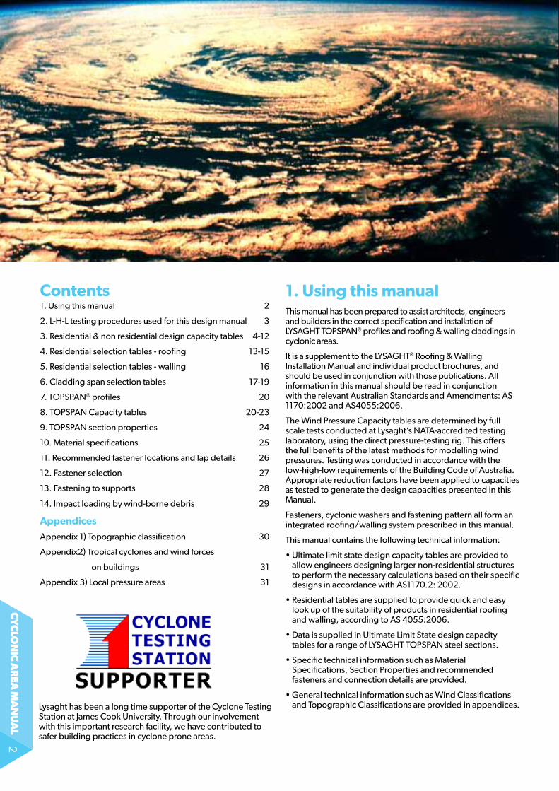
lysaght has been a long time supporter of the Cyclone testing Station at James Cook University. Through our involvement with this important research facility, we have contributed to safer building practices in cyclone prone areas.
cy
clo
nic
ar
ea m
an
ua
l3
the information in this document includes cyclonic capacities for a range of lYsagHt claddings and topspan® profiles.
these capacities are derived from extensive full scale cyclonic tests conducted at lysaght’s nata-accredited materials science testing laboratory.
Low-High-Low Pressure Sequence in Cyclonic Areas
the Building Code of australia (BCa) currently requires all roof claddings, fixing connections and immediate supporting members to withstand a low-high-low (lHl) cyclonic testing regime. topspan profiles are immediate supporting members according to the BCa definition, and as such, must be tested using the lHl cyclonic testing methodology to determine the outward capacity.
lysaght research & technology has performed comprehensive full scale tests of the entire range of claddings and topspan profiles. these tests were conducted on our direct air pressure rig in our testing laboratory.
2.L-H-L testing procedures used for this design manual
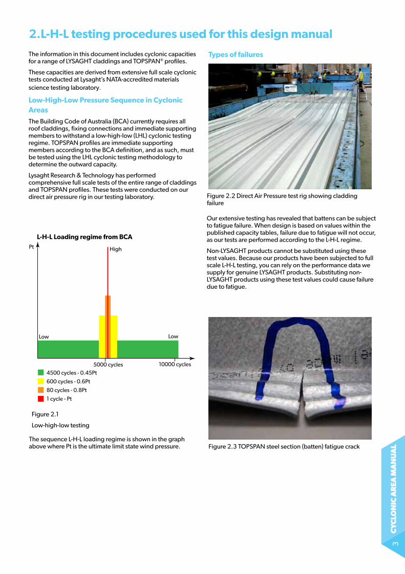
4500 cycles - 0.45Pt5000 cycles 10000 cycles
600 cycles - 0.6Pt
80 cycles - 0.8Pt
1 cycle - Pt
L-H-L Loading regime from BCA
Low Low
HighPt
figure 2.2 Direct air pressure test rig showing cladding failure
Types of failures
our extensive testing has revealed that battens can be subject to fatigue failure. When design is based on values within the published capacity tables, failure due to fatigue will not occur, as our tests are performed according to the l-H-l regime.
non-lYsagHt products cannot be substituted using these test values. Because our products have been subjected to full scale l-H-l testing, you can rely on the performance data we supply for genuine lYsagHt products. substituting non-lYsagHt products using these test values could cause failure due to fatigue.
the sequence l-H-l loading regime is shown in the graph above where pt is the ultimate limit state wind pressure. figure 2.3 topspan steel section (batten) fatigue crack
figure 2.1
low-high-low testing
cy
clo
nic
ar
ea m
an
ua
l4
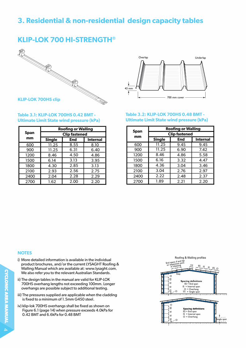
kLiP-Lok 700 Hi-STrengTH®
kLiP-Lok 700HS clip
Table 3.1: kLiP-Lok 700HS 0.42 BMT - Ultimate Limit State wind pressure (kPa)
ESIS
ES Single span
Spacing definitionsES = End spanIS = Internal spanO = Overhang
IS
O
O
Walling profiles only
Roofing & Walling profiles
Step
700 mm cover
43 mm
UnderlapOverlap
3. residential & non-residential design capacity tables
KLIP-LOK 700HS 0.42 BMT Limit States pressure (kPa)
Span Roofing or Walling
mm Clip fastened
Single End Internal600 8.10900 6.40
1200 4.861500 3.951800 3.132100 2.752400 2.292700 2.20
8.556.314.503.132.852.562.282.00
11.2511.258.466.144.302.932.041.62
KLIP-LOK 700HS 0.48 BMT Limit State wind pressure (kPa)
Span Roofing or Walling
mm Clip fastened
Single End Internal600 9.45900 7.42
1200 5.581500 4.471800 3.462100 2.972400 2.372700 2.20
9.456.904.863.323.042.762.482.21
11.2511.258.466.164.363.042.221.89
noTeS
i) More detailed information is available in the individual product brochures, and/or the current lYsagHt roofing & Walling Manual which are available at: www.lysaght.com. We also refer you to the relevant australian standards.
ii) the design tables in the manual are valid for Klip-loK 700Hs overhang lengths not exceeding 100mm. longer overhangs are possible subject to additional testing.
iii) the pressures supplied are applicable when the cladding is fixed to a minimum of 1.5mm g450 steel.
iv) klip-lok 700HS overhangs shall be fixed as shown on Figure 6.1 (page 14) when pressure exceeds 4.0kPa for 0.42 BMT and 6.6kPa for 0.48 BMT
Table 3.2: kLiP-Lok 700HS 0.48 BMT - Ultimate Limit State wind pressure (kPa)
cy
clo
nic
ar
ea m
an
ua
l5
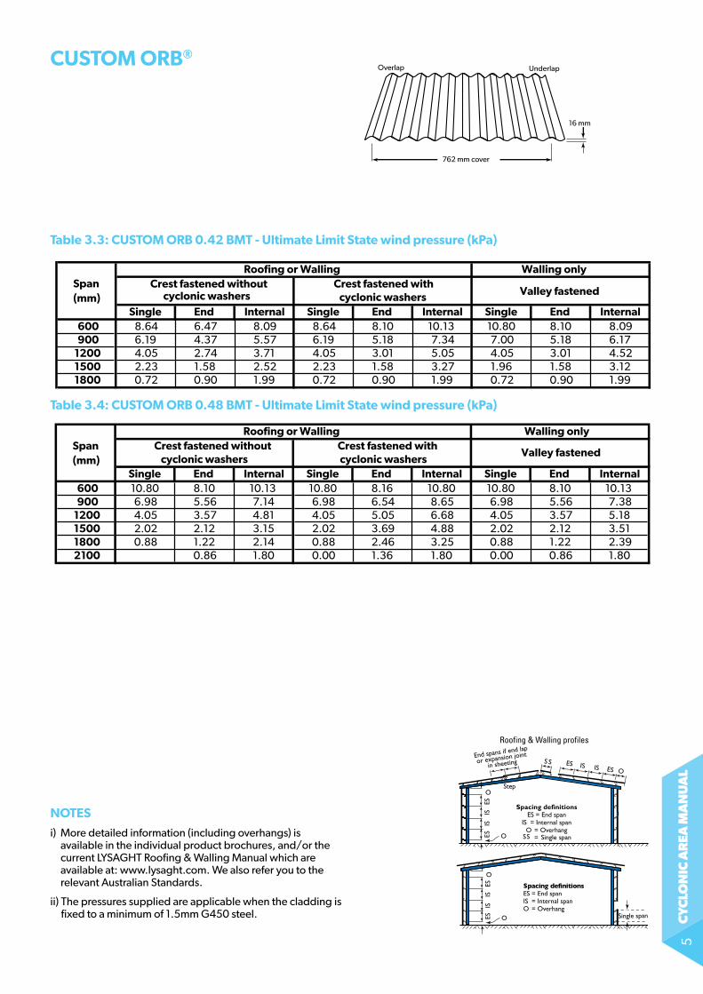
Table 3.3: CUSToM orB 0.42 BMT - Ultimate Limit State wind pressure (kPa)
Table 3.4: CUSToM orB 0.48 BMT - Ultimate Limit State wind pressure (kPa)
0.42 BMT CUSTOM ORB - Limit State pressure (kPa)
Span Roofing or Walling Walling only
(mm) Crest fastened without Crest fastened with
Valley fastened cyclonic washers cyclonic washersSingle End Internal Single End Internal Single End Internal
600 8.64 6.47 8.09 8.64 8.10 10.13 10.80 8.10 8.09900 6.19 4.37 5.57 6.19 5.18 7.34 7.00 5.18 6.17
1200 4.05 2.74 3.71 4.05 3.01 5.05 4.05 3.01 4.521500 2.23 1.58 2.52 2.23 1.58 3.27 1.96 1.58 3.121800 0.72 0.90 1.99 0.72 0.90 1.99 0.72 0.90 1.99
0.48 BMT CUSTOM ORB - Limit State pressure (kPa)
Span Roofing or Walling Walling only
(mm) Crest fastened without Crest fastened with
Valley fastened cyclonic washers cyclonic washers
Single End Internal Single End Internal Single End Internal600 10.80 8.10 10.13 10.80 8.16 10.80 10.80 8.10 10.13900 6.98 5.56 7.14 6.98 6.54 8.65 6.98 5.56 7.38
1200 4.05 3.57 4.81 4.05 5.05 6.68 4.05 3.57 5.181500 2.02 2.12 3.15 2.02 3.69 4.88 2.02 2.12 3.511800 0.88 1.22 2.14 0.88 2.46 3.25 0.88 1.22 2.392100 0.86 1.80 0.00 1.36 1.80 0.00 0.86 1.80
CUSToM orB®
762 mm cover
16 mm
UnderlapOverlap
ESIS
ES Single span
Spacing definitionsES = End spanIS = Internal spanO = Overhang
IS
O
O
Walling profiles only
Roofing & Walling profiles
Step
noTeS
i) More detailed information (including overhangs) is available in the individual product brochures, and/or the current lYsagHt roofing & Walling Manual which are available at: www.lysaght.com. We also refer you to the relevant australian standards.
ii) the pressures supplied are applicable when the cladding is fixed to a minimum of 1.5mm g450 steel.
cy
clo
nic
ar
ea m
an
ua
l6
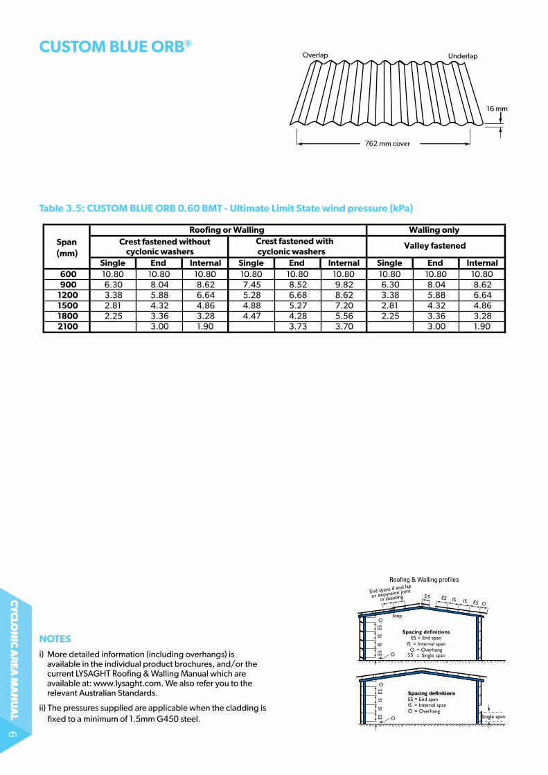
Table 3.5: CUSToM BLUe orB 0.60 BMT - Ultimate Limit State wind pressure (kPa)
CUSToM BLUe orB®
762 mm cover
16 mm
UnderlapOverlap
0.60 BMT CUSTOM BLUE ORB - Limit State pressure (kPa)
Span Roofing or Walling Walling only
(mm) Crest fastened without Crest fastened with Valley fastened cyclonic washers cyclonic washers
Single End Internal Single End Internal Single End Internal600 10.80 10.80 10.80 10.80 10.80 10.80 10.80 10.80 10.80900 6.30 8.04 8.62 7.45 8.52 9.82 6.30 8.04 8.62
1200 3.38 5.88 6.64 5.28 6.68 8.62 3.38 5.88 6.641500 2.81 4.32 4.86 4.88 5.27 7.20 2.81 4.32 4.861800 2.25 3.36 3.28 4.47 4.28 5.56 2.25 3.36 3.282100 3.00 1.90 3.73 3.70 3.00 1.90
ESIS
ES Single span
Spacing definitionsES = End spanIS = Internal spanO = Overhang
IS
O
O
Walling profiles only
Roofing & Walling profiles
Step
noTeS
i) More detailed information (including overhangs) is available in the individual product brochures, and/or the current lYsagHt roofing & Walling Manual which are available at: www.lysaght.com. We also refer you to the relevant australian standards.
ii) the pressures supplied are applicable when the cladding is fixed to a minimum of 1.5mm g450 steel.
cy
clo
nic
ar
ea m
an
ua
l7
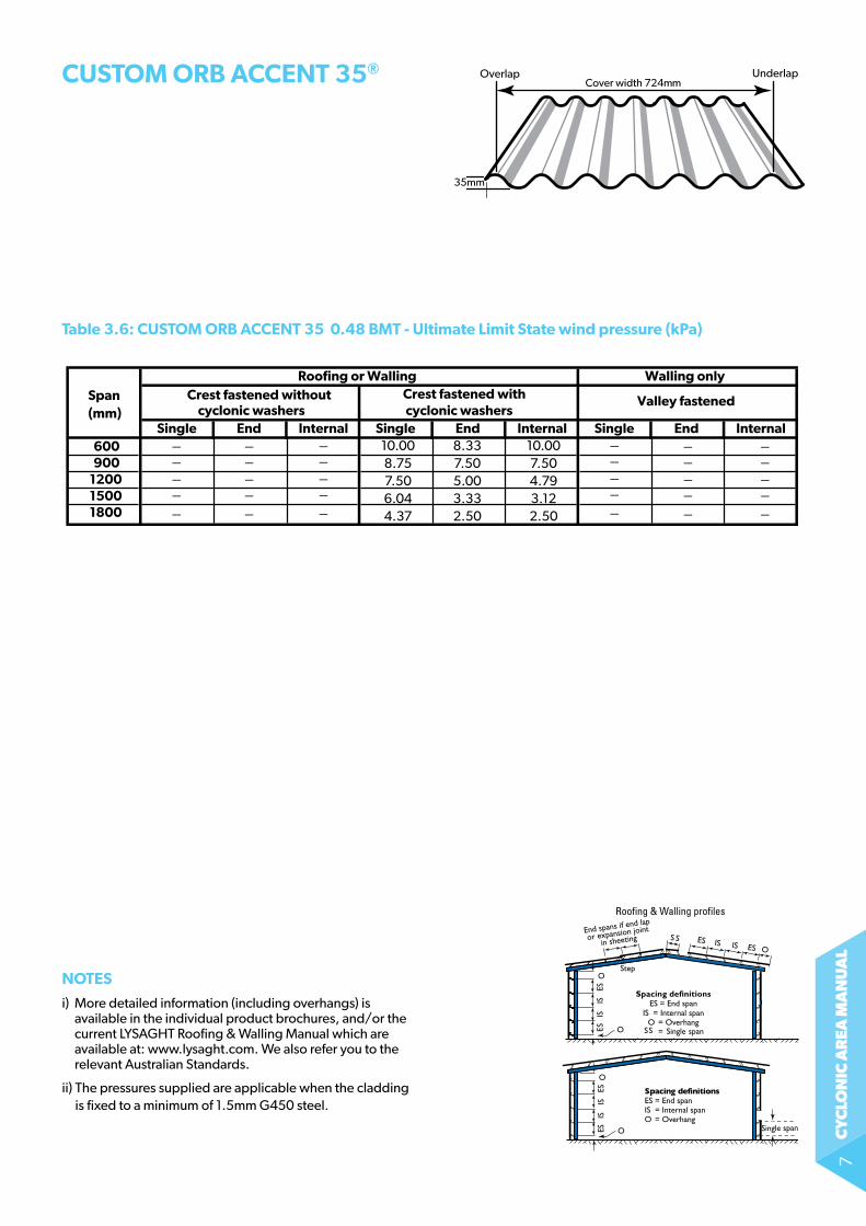
Table 3.6: CUSToM orB ACCenT 35 0.48 BMT - Ultimate Limit State wind pressure (kPa)
CUSToM orB ACCenT 35®
ESIS
ES Single span
Spacing definitionsES = End spanIS = Internal spanO = Overhang
IS
O
O
Walling profiles only
Roofing & Walling profiles
Step
noTeS
i) More detailed information (including overhangs) is available in the individual product brochures, and/or the current lYsagHt roofing & Walling Manual which are available at: www.lysaght.com. We also refer you to the relevant australian standards.
ii) the pressures supplied are applicable when the cladding is fixed to a minimum of 1.5mm g450 steel.
10.00 8.33 10.00 8.75 7.50 7.50 7.50 5.00 4.79 6.04 3.33 3.12 4.37 2.50 2.50
0.48 BMT CUSTOM ORB ACCENT 35 - Limit State pressure (kPa)
Span Roofing or Walling Walling only
(mm) Crest fastened without Crest fastened with Valley fastened cyclonic washers cyclonic washers
Single End Internal Single End Internal Single End Internal600900
120015001800
_____
_____
_____
_____
_____
_____
Overlap UnderlapCover width 724mm
35mm
cy
clo
nic
ar
ea m
an
ua
l8
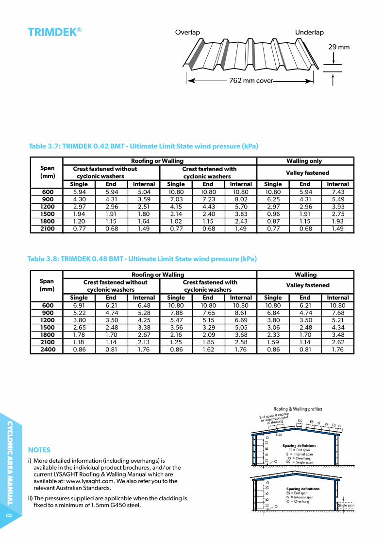
TriMdek® Overlap Underlap
762 mm cover
29 mm
Table 3.7: TriMdek 0.42 BMT - Ultimate Limit State wind pressure (kPa)
Table 3.8: TriMdek 0.48 BMT - Ultimate Limit State wind pressure (kPa)
0.42 BMT TRIMDEK - Limit State pressure (kPa)
Span Roofing or Walling Walling only
(mm) Crest fastened without Crest fastened with
Valley fastened cyclonic washers cyclonic washersSingle End Internal Single End Internal Single End Internal
600 5.94 5.94 5.04 10.80 10.80 10.80 10.80 5.94 7.43900 4.30 4.31 3.59 7.03 7.23 8.02 6.25 4.31 5.49
1200 2.97 2.96 2.51 4.15 4.43 5.70 2.97 2.96 3.931500 1.94 1.91 1.80 2.14 2.40 3.83 0.96 1.91 2.751800 1.20 1.15 1.64 1.02 1.15 2.43 0.87 1.15 1.932100 0.77 0.68 1.49 0.77 0.68 1.49 0.77 0.68 1.49
0.48 BMT TRIMDEK - Limit State pressure (kPa)
Span Roofing or Walling Walling
(mm) Crest fastened without Crest fastened with Valley fastened cyclonic washers cyclonic washers
Single End Internal Single End Internal Single End Internal600 6.91 6.21 6.48 10.80 10.80 10.80 10.80 6.21 10.80900 5.22 4.74 5.28 7.88 7.65 8.61 6.84 4.74 7.68
1200 3.80 3.50 4.25 5.47 5.15 6.69 3.80 3.50 5.211500 2.65 2.48 3.38 3.56 3.29 5.05 3.06 2.48 4.341800 1.78 1.70 2.67 2.16 2.09 3.68 2.33 1.70 3.482100 1.18 1.14 2.13 1.25 1.85 2.58 1.59 1.14 2.622400 0.86 0.81 1.76 0.86 1.62 1.76 0.86 0.81 1.76
ESIS
ES Single span
Spacing definitionsES = End spanIS = Internal spanO = Overhang
IS
O
O
Walling profiles only
Roofing & Walling profiles
Step
noTeS
i) More detailed information (including overhangs) is available in the individual product brochures, and/or the current lYsagHt roofing & Walling Manual which are available at: www.lysaght.com. We also refer you to the relevant australian standards.
ii) the pressures supplied are applicable when the cladding is fixed to a minimum of 1.5mm g450 steel.
cy
clo
nic
ar
ea m
an
ua
l9
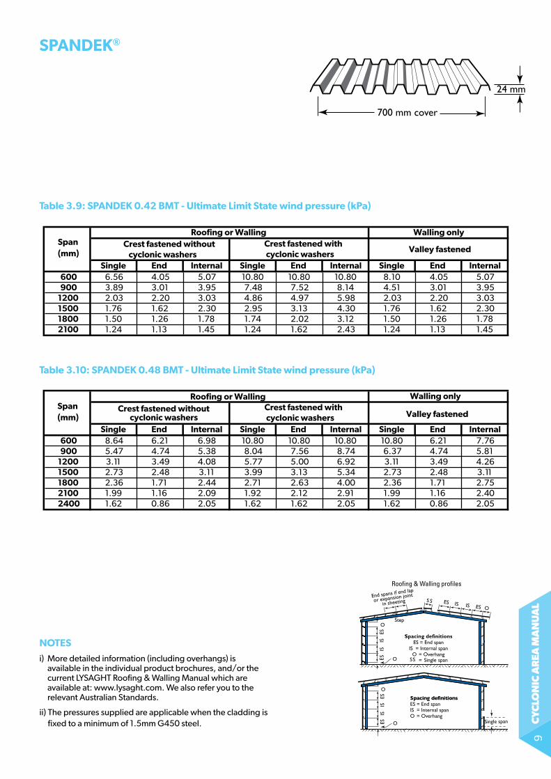
Table 3.9: SPAndek 0.42 BMT - Ultimate Limit State wind pressure (kPa)0.42 BMT SPANDEK - Limit State pressure (kPa)
Span Roofing or Walling Walling only
(mm) Crest fastened without Crest fastened with
Valley fastened cyclonic washers cyclonic washers
Single End Internal Single End Internal Single End Internal600 6.56 4.05 5.07 10.80 10.80 10.80 8.10 4.05 5.07900 3.89 3.01 3.95 7.48 7.52 8.14 4.51 3.01 3.95
1200 2.03 2.20 3.03 4.86 4.97 5.98 2.03 2.20 3.031500 1.76 1.62 2.30 2.95 3.13 4.30 1.76 1.62 2.301800 1.50 1.26 1.78 1.74 2.02 3.12 1.50 1.26 1.782100 1.24 1.13 1.45 1.24 1.62 2.43 1.24 1.13 1.45
Table 3.10: SPAndek 0.48 BMT - Ultimate Limit State wind pressure (kPa)0.48 BMT SPANDEK - Limit State pressure (kPa)
Span Roofing or Walling Walling only
(mm) Crest fastened without Crest fastened with
Valley fastened cyclonic washers cyclonic washersSingle End Internal Single End Internal Single End Internal
600 8.64 6.21 6.98 10.80 10.80 10.80 10.80 6.21 7.76900 5.47 4.74 5.38 8.04 7.56 8.74 6.37 4.74 5.81
1200 3.11 3.49 4.08 5.77 5.00 6.92 3.11 3.49 4.261500 2.73 2.48 3.11 3.99 3.13 5.34 2.73 2.48 3.111800 2.36 1.71 2.44 2.71 2.63 4.00 2.36 1.71 2.752100 1.99 1.16 2.09 1.92 2.12 2.91 1.99 1.16 2.402400 1.62 0.86 2.05 1.62 1.62 2.05 1.62 0.86 2.05
SPAndek®
700 mm cover
24 mm
ESIS
ES Single span
Spacing definitionsES = End spanIS = Internal spanO = Overhang
IS
O
O
Walling profiles only
Roofing & Walling profiles
Step
noTeS
i) More detailed information (including overhangs) is available in the individual product brochures, and/or the current lYsagHt roofing & Walling Manual which are available at: www.lysaght.com. We also refer you to the relevant australian standards.
ii) the pressures supplied are applicable when the cladding is fixed to a minimum of 1.5mm g450 steel.
cy
clo
nic
ar
ea m
an
ua
l10
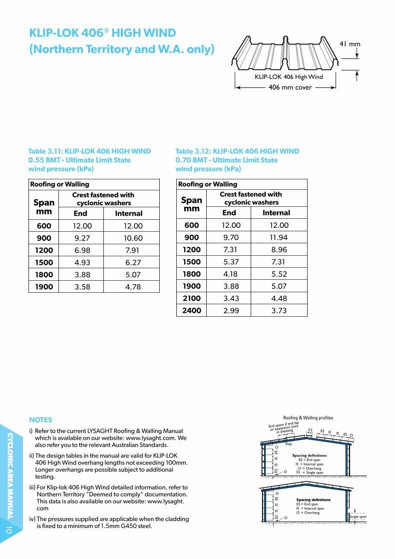
kLiP-Lok 406® HigH wind(northern Territory and w.A. only)
406 mm cover
41 mm
KLIP-LOK 406 High Wind
Span
600
900
1200
1500
1800
Crest fastened with cyclonic washers
End Internal
Roofing or Walling Roofing or Walling
1900
Span
600
900
1200
1500
1800
Crest fastened with cyclonic washers
End Internal
1900
2100
12.00
9.27
6.98
4.93
3.88
12.00
10.60
7.91
6.27
5.07
3.58 4.78
2400
12.00
9.70
7.31
5.37
4.18
12.00
11.94
8.96
7.31
5.52
3.88 5.07
3.43 4.48
2.99 3.73
mmmm
Table 3.11: kLiP-Lok 406 HigH wind0.55 BMT - Ultimate Limit State wind pressure (kPa)
Table 3.12: kLiP-Lok 406 HigH wind0.70 BMT - Ultimate Limit State wind pressure (kPa)
ESIS
ES Single span
Spacing definitionsES = End spanIS = Internal spanO = Overhang
IS
O
O
Walling profiles only
Roofing & Walling profiles
Step
noTeS
i) refer to the current lYsagHt roofing & Walling Manual which is available on our website: www.lysaght.com. We also refer you to the relevant australian standards.
ii) the design tables in the manual are valid for Klip-loK 406 High Wind overhang lengths not exceeding 100mm. longer overhangs are possible subject to additional testing.
iii) For Klip-lok 406 High Wind detailed information, refer to northern territory “Deemed to comply” documentation. this data is also available on our website: www.lysaght.com
iv) the pressures supplied are applicable when the cladding is fixed to a minimum of 1.5mm g450 steel.
cy
clo
nic
ar
ea m
an
ua
l11
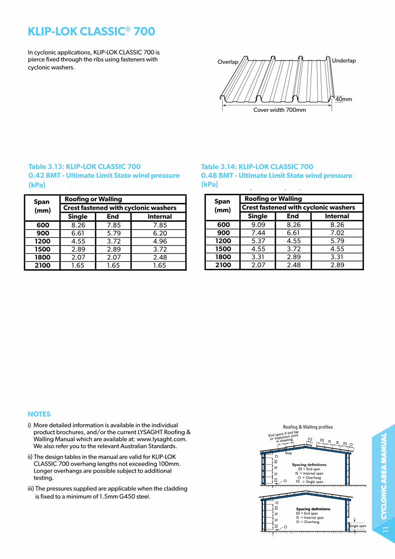
in cyclonic applications, Klip-loK ClassiC 700 is pierce fixed through the ribs using fasteners with cyclonic washers.
kLiP-Lok CLASSiC® 700
Table 3.13: kLiP-Lok CLASSiC 700 0.42 BMT - Ultimate Limit State wind pressure (kPa)
ESIS
ES Single span
Spacing definitionsES = End spanIS = Internal spanO = Overhang
IS
O
O
Walling profiles only
Roofing & Walling profiles
Step
Cover width 700mm
Overlap Underlap
40mm
KLIP-LOK 700 Classic 0.42 BMT KLIP-LOK 700 Classic 0.48 BMTLimit States pressure (kPa) Limit States pressure (kPa)
Span Roofing or Walling Span Roofing or Walling
(mm) Crest fastened with cyclonic washers (mm) Crest fastened with cyclonic washersSingle End Internal Single End Internal
600 8.26 7.85 7.85 600 9.09 8.26 8.26900 6.61 5.79 6.20 900 7.44 6.61 7.02
1200 4.55 3.72 4.96 1200 5.37 4.55 5.791500 2.89 2.89 3.72 1500 4.55 3.72 4.551800 2.07 2.07 2.48 1800 3.31 2.89 3.312100 1.65 1.65 1.65 2100 2.07 2.48 2.89
noTeS
i) More detailed information is available in the individual product brochures, and/or the current lYsagHt roofing & Walling Manual which are available at: www.lysaght.com. We also refer you to the relevant australian standards.
ii) the design tables in the manual are valid for Klip-loK ClassiC 700 overhang lengths not exceeding 100mm. longer overhangs are possible subject to additional testing.
iii) the pressures supplied are applicable when the cladding is fixed to a minimum of 1.5mm g450 steel.
Table 3.14: kLiP-Lok CLASSiC 700 0.48 BMT - Ultimate Limit State wind pressure (kPa)
cy
clo
nic
ar
ea m
an
ua
l12
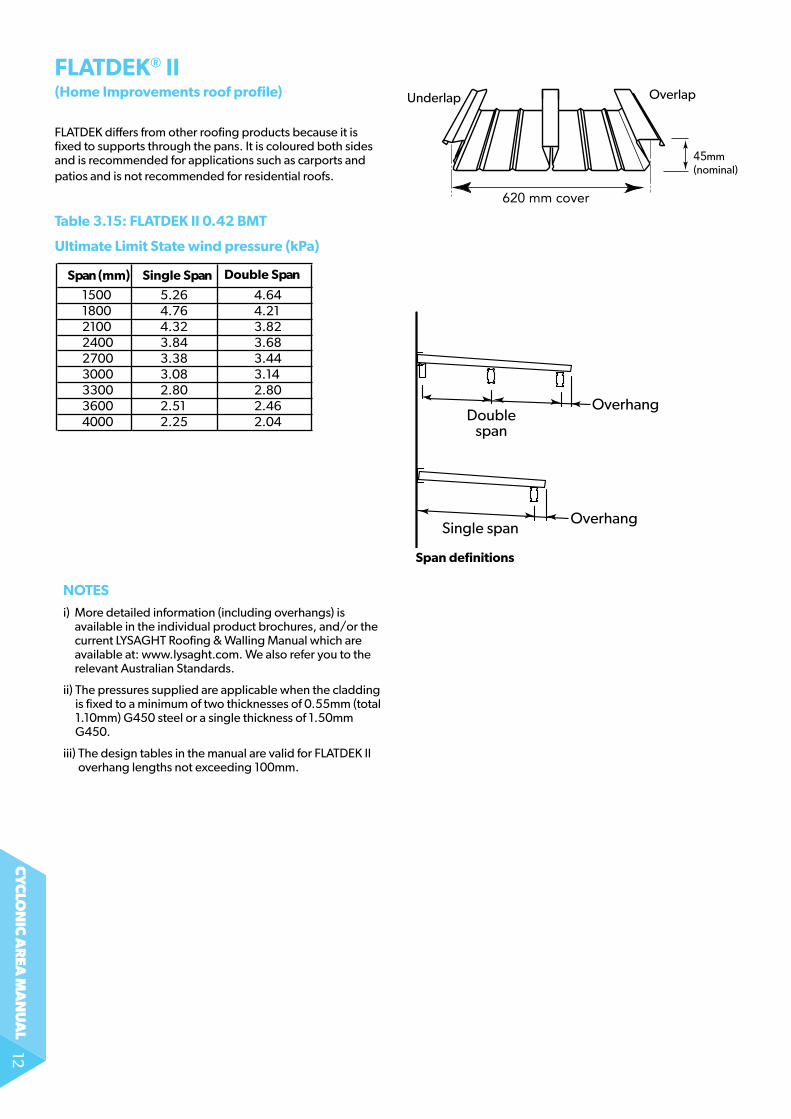
flatDeK differs from other roofing products because it is fixed to supports through the pans. it is coloured both sides and is recommended for applications such as carports and patios and is not recommended for residential roofs.
fLATdek® ii (Home improvements roof profile)
Span (mm) Single Span Double Span
150018002100240027003000330036004000
5.26 4.644.76 4.214.32 3.823.84 3.683.38 3.443.08 3.142.80 2.802.51 2.462.25 2.04
Note: Reduction Factor of 0.8 has been applied.
Span definitions
OverlapUnderlap
mm(nominal)
Single span
OverhangDouble
span
Overhang
Table 3.15: fLATdek ii 0.42 BMT
Ultimate Limit State wind pressure (kPa)
noTeS
i) More detailed information (including overhangs) is available in the individual product brochures, and/or the current lYsagHt roofing & Walling Manual which are available at: www.lysaght.com. We also refer you to the relevant australian standards.
ii) the pressures supplied are applicable when the cladding is fixed to a minimum of two thicknesses of 0.55mm (total 1.10mm) G450 steel or a single thickness of 1.50mm g450.
iii) the design tables in the manual are valid for flatDeK ii overhang lengths not exceeding 100mm.
cy
clo
nic
ar
ea m
an
ua
l13
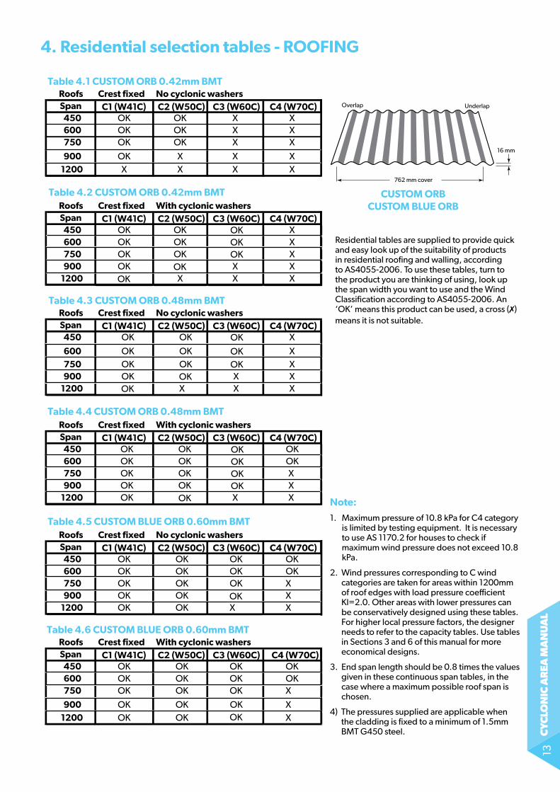
4. residential selection tables - roofing
Table 4.1 CUSTOM ORB 0.42mm BMTRoofs Crest fixed No cyclonic washersSpan C1 (W41C) C2 (W50C) C3 (W60C) C4 (W70C)
450 OK OK X X600 OK OK X X750 OK OK X X
900 OK X X X1200 X X X X
Table 4.2 CUSTOM ORB 0.42mm BMTRoofs Crest fixed With cyclonic washersSpan C1 (W41C) C2 (W50C) C3 (W60C) C4 (W70C)
450 OK OK X600 OK OK X750 OK OK
OKOKOK X
900 OK OKOK
X X1200 X X X
Table 4.3 CUSTOM ORB 0.48mm BMTRoofs Crest fixed No cyclonic washersSpan C1 (W41C) C2 (W50C) C3 (W60C) C4 (W70C)
450 OK OK X
600 OK OK X750 OK OK
OK
OKOK X
900 OK OKOK
X X1200 X X X
Table 4.4 CUSTOM ORB 0.48mm BMTRoofs Crest fixed With cyclonic washersSpan C1 (W41C) C2 (W50C) C3 (W60C) C4 (W70C)
450 OK OK600 OK OK750 OK OK X900 OK OK
OK
OKOK
OKOK
OKOK X
1200 OK X X
Table 4.5 CUSTOM BLUE ORB 0.60mm BMTRoofs Crest fixed No cyclonic washersSpan C1 (W41C) C2 (W50C) C3 (W60C) C4 (W70C)
450 OK OK OK OK600 OK OK OK OK750 OK OK OK
OKX
900 OK OK X1200 OK OK X X
Table 4.6 CUSTOM BLUE ORB 0.60mm BMTRoofs Crest fixed With cyclonic washersSpan C1 (W41C) C2 (W50C) C3 (W60C) C4 (W70C)
450 OK OK OK OK600 OK OK OK OK750 OK OK OK X
900 OK OKOKOK X
1200 OK OK X
762 mm cover
16 mm
UnderlapOverlap
CUSToM orB CUSToM BLUe orB
note:
1. Maximum pressure of 10.8 kPa for C4 category is limited by testing equipment. it is necessary to use AS 1170.2 for houses to check if maximum wind pressure does not exceed 10.8 kPa.
2. Wind pressures corresponding to C wind categories are taken for areas within 1200mm of roof edges with load pressure coefficient Kl=2.0. other areas with lower pressures can be conservatively designed using these tables. for higher local pressure factors, the designer needs to refer to the capacity tables. Use tables in sections 3 and 6 of this manual for more economical designs.
3. end span length should be 0.8 times the values given in these continuous span tables, in the case where a maximum possible roof span is chosen.
4) the pressures supplied are applicable when the cladding is fixed to a minimum of 1.5mm BMt g450 steel.
Residential tables are supplied to provide quick and easy look up of the suitability of products in residential roofing and walling, according to as4055-2006. to use these tables, turn to the product you are thinking of using, look up the span width you want to use and the Wind Classification according to as4055-2006. an ‘oK’ means this product can be used, a cross (7) means it is not suitable.

cy
clo
nic
ar
ea m
an
ua
l14
Table 4.7 TRIMDEK 0.42 BMTRoofs Crest fixed No cyclonic washersSpan C1 (W41C) C2 (W50C) C3 (W60C) C4 (W70C)
450 OK X X600 OK
OKOK X X
750 OK X X X900 OK X X X
1200 X X X X
Table 4.8 TRIMDEK 0.42 BMTRoofs Crest fixed With cyclonic washersSpan C1 (W41C) C2 (W50C) C3 (W60C) C4 (W70C)
450 OK OK OK OK600 OK OK OK OK750 OK OK OK X900 OK OK
OKX X
1200 OK X X
Table 4.9 TRIMDEK 0.48 BMTRoofs Crest fixed No cyclonic washersSpan C1 (W41C) C2 (W50C) C3 (W60C) C4 (W70C)
450 OK OK X X600 OK OK
OKX X
750 OK X X900 OK
OKX X X
1200 X X X
Table 4.10 TRIMDEK 0.48 BMTRoofs Crest fixed With cyclonic washersSpan C1 (W41C) C2 (W50C) C3 (W60C) C4 (W70C)
450 OK OK OK OK600 OK OK OK OK750 OK OK OK X900 OK OK OK
OKX
1200 OK X X
TriMdek
note:
1. Maximum pressure of 10.8 kPa for C4 category is limited by testing equipment. it is necessary to use as 1170.2 for houses to check if maximum wind pressure does not exceed 10.8 kPa.
2. Wind pressures corresponding to C wind categories are taken for areas within 1200mm of roof edges with load pressure coefficient Kl=2.0. other areas with lower pressures can be conservatively designed using these tables. for higher local pressure factors, the designer needs to refer to the capacity tables. Use tables in sections 3 and 6 of this manual for more economical designs.
3. end span length should be 0.8 times the values given in these continuous span tables, in the case where a maximum possible roof span is chosen.
4) the pressures supplied are applicable when the cladding is fixed to a minimum of 1.5mm BMt g450 steel.
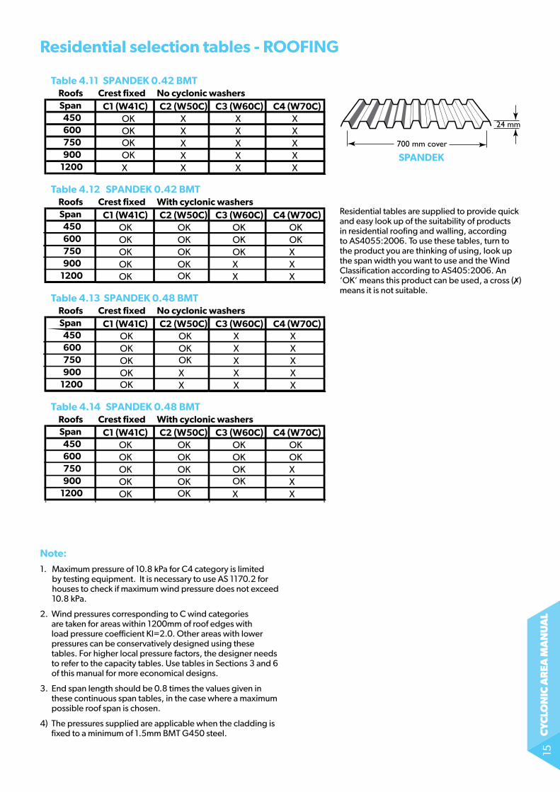
residential selection tables - roofing
Overlap Underlap
762 mm cover
29 mm
Residential tables are supplied to provide quick and easy look up of the suitability of products in residential roofing and walling, according to as4055-2006. to use these tables, turn to the product you are thinking of using, look up the span width you want to use and the Wind Classification according to as4055-2006. an ‘oK’ means this product can be used, a cross (7) means it is not suitable.
cy
clo
nic
ar
ea m
an
ua
l15
Table 4.11 SPANDEK 0.42 BMTRoofs Crest fixed No cyclonic washersSpan C1 (W41C) C2 (W50C) C3 (W60C) C4 (W70C)
450 OK X X X600 OK
OKOK
X X X750 X X X900 X X X
1200 X X X X
Table 4.12 SPANDEK 0.42 BMTRoofs Crest fixed With cyclonic washersSpan C1 (W41C) C2 (W50C) C3 (W60C) C4 (W70C)
450 OK OK OK OK600 OK OK OK OK750 OK OK OK X900 OK OK
OKX X
1200 OK X X
Table 4.13 SPANDEK 0.48 BMTRoofs Crest fixed No cyclonic washersSpan C1 (W41C) C2 (W50C) C3 (W60C) C4 (W70C)
450 OK OK X X600 OK OK X X750 OK X X900 OK
OK
OKX X X
1200 X X X
Table 4.14 SPANDEK 0.48 BMTRoofs Crest fixed With cyclonic washersSpan C1 (W41C) C2 (W50C) C3 (W60C) C4 (W70C)
450 OK OK OK OK600 OK OK OK OK750 OK OK OK X900 OK OK OK
OKX
1200 OK X X
700 mm cover
24 mm
SPAndek
residential selection tables - roofing
note:
1. Maximum pressure of 10.8 kPa for C4 category is limited by testing equipment. it is necessary to use as 1170.2 for houses to check if maximum wind pressure does not exceed 10.8 kPa.
2. Wind pressures corresponding to C wind categories are taken for areas within 1200mm of roof edges with load pressure coefficient Kl=2.0. other areas with lower pressures can be conservatively designed using these tables. for higher local pressure factors, the designer needs to refer to the capacity tables. Use tables in Sections 3 and 6 of this manual for more economical designs.
3. end span length should be 0.8 times the values given in these continuous span tables, in the case where a maximum possible roof span is chosen.
4) the pressures supplied are applicable when the cladding is fixed to a minimum of 1.5mm BMt g450 steel.
Residential tables are supplied to provide quick and easy look up of the suitability of products in residential roofing and walling, according to as4055:2006. to use these tables, turn to the product you are thinking of using, look up the span width you want to use and the Wind Classification according to as405:2006. an ‘oK’ means this product can be used, a cross (7) means it is not suitable.
cy
clo
nic
ar
ea m
an
ua
l16
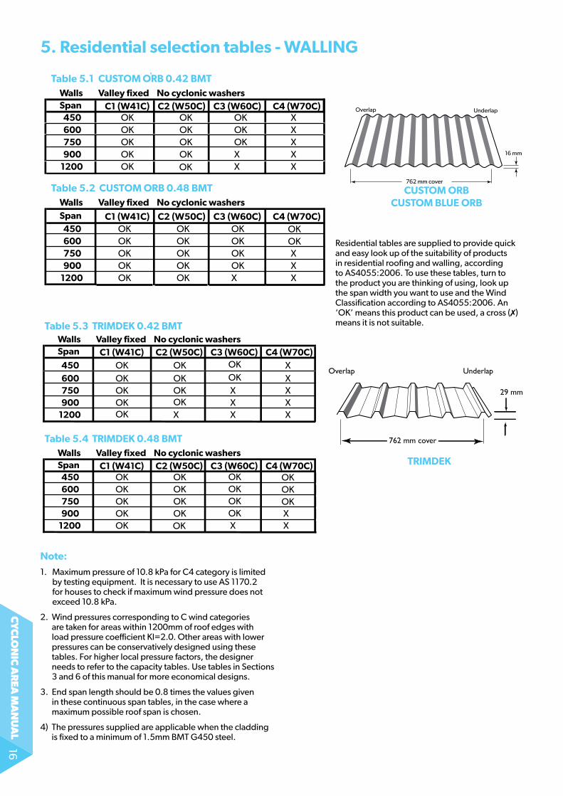
5. residential selection tables - wALLing
762 mm cover
16 mm
UnderlapOverlap
Table 5.1 CUSTOM ORB 0.42 BMTWalls Valley fixed No cyclonic washersSpan C1 (W41C) C2 (W50C) C3 (W60C) C4 (W70C)
450 OK OK OK X600 OK OK OK X750 OK OK OK X900 OK OK
OKX X
1200 OK X X
Table 5.2 CUSTOM ORB 0.48 BMTWalls Valley fixed No cyclonic washersSpan C1 (W41C) C2 (W50C) C3 (W60C) C4 (W70C)
450 OK OK OK600 OK OK OK
OKOK
750 OK OK OK X900 OK OK OK
OKX
1200 OK X X
CUSToM orB CUSToM BLUe orB
Overlap Underlap
762 mm cover
29 mm
TriMdek
Table 5.3 TRIMDEK 0.42 BMTWalls Valley fixed No cyclonic washersSpan C1 (W41C) C2 (W50C) C3 (W60C) C4 (W70C)
450 OK OK X600 OK OK
OKOK X
750 OK OK X X900 OK OK
OKX X
1200 X X X
Table 5.4 TRIMDEK 0.48 BMTWalls Valley fixed No cyclonic washersSpan C1 (W41C) C2 (W50C) C3 (W60C) C4 (W70C)
450 OK OK600 OK OK750 OK OK900 OK OK
OKOKOK
OKOKOK
OKOK
X1200 OK X X
note:
1. Maximum pressure of 10.8 kPa for C4 category is limited by testing equipment. it is necessary to use as 1170.2 for houses to check if maximum wind pressure does not exceed 10.8 kPa.
2. Wind pressures corresponding to C wind categories are taken for areas within 1200mm of roof edges with load pressure coefficient Kl=2.0. other areas with lower pressures can be conservatively designed using these tables. for higher local pressure factors, the designer needs to refer to the capacity tables. Use tables in Sections 3 and 6 of this manual for more economical designs.
3. end span length should be 0.8 times the values given in these continuous span tables, in the case where a maximum possible roof span is chosen.
4) the pressures supplied are applicable when the cladding is fixed to a minimum of 1.5mm BMt g450 steel.
Residential tables are supplied to provide quick and easy look up of the suitability of products in residential roofing and walling, according to as4055:2006. to use these tables, turn to the product you are thinking of using, look up the span width you want to use and the Wind Classification according to as4055:2006. an ‘oK’ means this product can be used, a cross (7) means it is not suitable.
cy
clo
nic
ar
ea m
an
ua
l17
notes:
1. fastening shall comply with sections 12 & 13 of this Manual.
2. Fixing to steel supports with thickness between 0.75 and 1.5mm may also result in reduced maximum spans due to reduced screw pull-out capacity.
3. Ultimate Limit State Wind pressure corresponding to AS 4055:2006 wind classification in this table refers to roof areas within 1200mm. (Kl = 2.0) according to as 4055:2006 table 3.3. except for C4 wind category where pressures are given for areas away from edges and within 1200mm of edges. Different pressures will apply on other roof and wall areas.
4. When pressure is calculated in accordance to as/nZs 1170.2:2002 following parameters shall be used:
Cpi = +0.7 and -0.65
Kc = 1.0
Kl = 1.5 and 2.0. Kl = 3.0 may be necessary for walls of tall (>25m) buildings.
5. outdated W classification is given as approximate reference only.
6. Maximum pressure of 10.8 kPa for C4 category is limited by testing equipment. It is necessary to use AS/NZS1170.2 for houses to check if maximum wind pressure does not exceed 10.8 kPa.
7. no washers are required for Klip-loK-700 Hi-strength since it is used as a concealed fixed cladding.
8. the spans supplied are applicable when the cladding is fixed to a minimum of 1.5mm g450 steel.
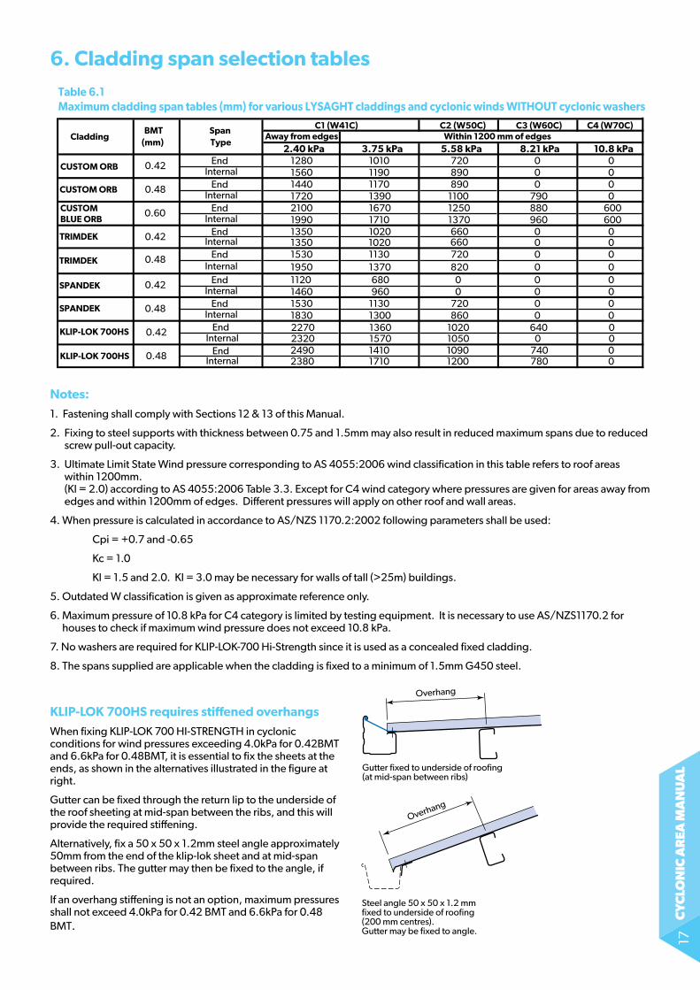
6. Cladding span selection tablesTable 6.1Maximum cladding span tables (mm) for various LYSAGHT claddings and cyclonic winds WITHOUT cyclonic washers
BMT Span C1 (W41C) C2 (W50C) C3 (W60C) C4 (W70C)Cladding
(mm) TypeAway from edges Within 1200 mm of edges
2.40 kPa 3.75 kPa 5.58 kPa 8.21 kPa 10.8 kPa
CUSTOM BLUE ORB
CUSTOM ORB
CUSTOM ORB
0.42 End 1280 1010 720 0 0Internal 1560 1190 890 0 0
0.48 End 1440 1170 890 0 0Internal 1720 1390 1100 790 0
0.60 End 2100 1670 1250 880 600Internal 1990 1710 1370 960 600
TRIMDEK 0.42 End 1350 1020 660660
0 0Internal 1350 1020 0 0
TRIMDEK 0.48 End 1530 1130 720 0 0Internal 1950 1370 820 0 0
SPANDEK
SPANDEK
0.42 End 1120 680 0 0 0Internal 1460 960 0 0 0
0.48 End 1530 1130 720 0 01830 1300 860 0 0Internal
2380 1710 1200 780 0
2320 1570 1050 0 02490 1410 1090 740 0
2270 1360 1020 640 0KLIP-LOK 700HS
KLIP-LOK 700HS
0.42 End Internal
0.48 End Internal
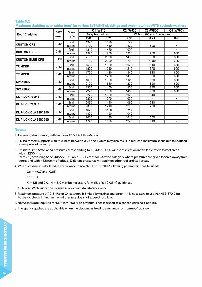
Table 6.2 Maximum cladding span tables (mm) for various LYSAGHT claddings and cyclonic winds WITH cyclonic washers
RoofBMT Span C1 (W41C) C2 (W50C) C3 (W60C) C4 (W70C)
Cladding (mm) Type Away from edges Within 1200 mm from edges2.40 3.75 5.58 8.21 10.8
CUSTOM ORB 0.42 End 1320 1090 850Internal 1700 1410 1130 800
CUSTOM ORB 0.48 End 1810 1480 1090Internal 1970 1700 1380 960 600
CUSTOM BLUE ORB 0.60 End 2100 2080 1430 950 600Internal 2100 2090 1790 1280 600
TRIMDEK 0.42 End 1500 1300 1070 810 600Internal 1800 1510 1210 870 600
TRIMDEK 0.48 End 1720 1420 1140 840 600Internal 2160 1780 1400 960 600
SPANDEK 0.42 End 1690 1390 1120 830 600Internal 2100 1640 1270 890 600
SPANDEK 0.48 End 1930 1400 1130 830 600Internal 2270 1860 1450 980 600
KLIP-LOK 700HS 0.42 End 2270 1360 1020 640Internal 2320 1570 1050
KLIP-LOK 700HS 0.48 End 2490 1410 1090 740Internal 2380 1710 1200 780
KLIP-LOK CLASSIC 700 0.42 End 1670 1190 920Internal 1820 1490 1040
KLIP-LOK CLASSIC 700 0.48 End 2030 1480 1040 600Internal 1740 1690 1240 610
------
--
--
--
-
-
--
kLiP-Lok 700HS requires stiffened overhangs
When fixing Klip-loK 700 Hi-strengtH in cyclonic conditions for wind pressures exceeding 4.0kPa for 0.42BMT and 6.6kPa for 0.48BMT, it is essential to fix the sheets at the ends, as shown in the alternatives illustrated in the figure at right.
gutter can be fixed through the return lip to the underside of the roof sheeting at mid-span between the ribs, and this will provide the required stiffening.
alternatively, fix a 50 x 50 x 1.2mm steel angle approximately 50mm from the end of the klip-lok sheet and at mid-span between ribs. the gutter may then be fixed to the angle, if required.
if an overhang stiffening is not an option, maximum pressures shall not exceed 4.0kPa for 0.42 BMT and 6.6kPa for 0.48 BMt.
Steel angle 50 x 50 x 1.2 mmfixed to underside of roofing(200 mm centres).Gutter may be fixed to angle.
Gutter fixed to underside of roofing(at mid-span between ribs)
Overhang
Overhang
Figure 6.1
cy
clo
nic
ar
ea m
an
ua
l18
notes:
1. fastening shall comply with sections 12 & 13 of this Manual.
2. Fixing to steel supports with thickness between 0.75 and 1.5mm may also result in reduced maximum spans due to reduced screw pull-out capacity.
3. Ultimate Limit State Wind pressure corresponding to AS 4055:2006 wind classification in this table refers to roof areas within 1200mm. (Kl = 2.0) according to as 4055:2006 table 3.3. except for C4 wind category where pressures are given for areas away from edges and within 1200mm of edges. Different pressures will apply on other roof and wall areas.
4. When pressure is calculated in accordance to as/nZs 1170.2:2002 following parameters shall be used:
Cpi = +0.7 and -0.65
Kc = 1.0
Kl = 1.5 and 2.0. Kl = 3.0 may be necessary for walls of tall (>25m) buildings.
5. outdated W classification is given as approximate reference only.
6. Maximum pressure of 10.8 kPa for C4 category is limited by testing equipment. It is necessary to use AS/NZS1170.2 for houses to check if maximum wind pressure does not exceed 10.8 kPa.
7. no washers are required for Klip-loK-700 High strength since it is used as a concealed fixed cladding.
8. the spans supplied are applicable when the cladding is fixed to a minimum of 1.5mm g450 steel.
Table 6.1Maximum cladding span tables (mm) for various LYSAGHT claddings and cyclonic winds WITHOUT cyclonic washers
BMT Span C1 (W41C) C2 (W50C) C3 (W60C) C4 (W70C)Cladding
(mm) TypeAway from edges Within 1200 mm of edges
2.40 kPa 3.75 kPa 5.58 kPa 8.21 kPa 10.8 kPa
CUSTOM BLUE ORB
CUSTOM ORB
CUSTOM ORB
0.42 End 1280 1010 720 0 0Internal 1560 1190 890 0 0
0.48 End 1440 1170 890 0 0Internal 1720 1390 1100 790 0
0.60 End 2100 1670 1250 880 600Internal 1990 1710 1370 960 600
TRIMDEK 0.42 End 1350 1020 660660
0 0Internal 1350 1020 0 0
TRIMDEK 0.48 End 1530 1130 720 0 0Internal 1950 1370 820 0 0
SPANDEK
SPANDEK
0.42 End 1120 680 0 0 0Internal 1460 960 0 0 0
0.48 End 1530 1130 720 0 01830 1300 860 0 0Internal
2380 1710 1200 780 0
2320 1570 1050 0 02490 1410 1090 740 0
2270 1360 1020 640 0KLIP-LOK 700HS
KLIP-LOK 700HS
0.42 End Internal
0.48 End Internal
Table 6.2 Maximum cladding span tables (mm) for various LYSAGHT claddings and cyclonic winds WITH cyclonic washers
RoofBMT Span C1 (W41C) C2 (W50C) C3 (W60C) C4 (W70C)
Cladding (mm) Type Away from edges Within 1200 mm from edges2.40 3.75 5.58 8.21 10.8
CUSTOM ORB 0.42 End 1320 1090 850Internal 1700 1410 1130 800
CUSTOM ORB 0.48 End 1810 1480 1090Internal 1970 1700 1380 960 600
CUSTOM BLUE ORB 0.60 End 2100 2080 1430 950 600Internal 2100 2090 1790 1280 600
TRIMDEK 0.42 End 1500 1300 1070 810 600Internal 1800 1510 1210 870 600
TRIMDEK 0.48 End 1720 1420 1140 840 600Internal 2160 1780 1400 960 600
SPANDEK 0.42 End 1690 1390 1120 830 600Internal 2100 1640 1270 890 600
SPANDEK 0.48 End 1930 1400 1130 830 600Internal 2270 1860 1450 980 600
KLIP-LOK 700HS 0.42 End 2270 1360 1020 640Internal 2320 1570 1050
KLIP-LOK 700HS 0.48 End 2490 1410 1090 740Internal 2380 1710 1200 780
KLIP-LOK CLASSIC 700 0.42 End 1670 1190 920Internal 1820 1490 1040
KLIP-LOK CLASSIC 700 0.48 End 2030 1480 1040 600Internal 1740 1690 1240 610
------
--
--
--
-
-
--
cy
clo
nic
ar
ea m
an
ua
l19
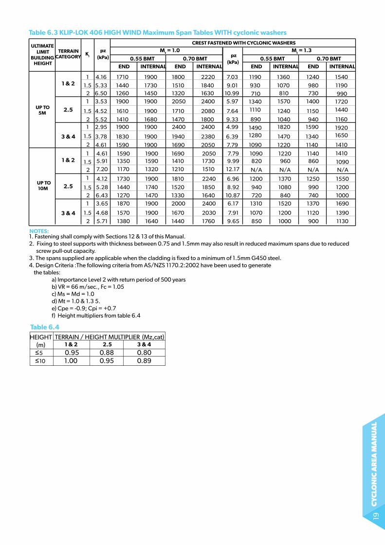
Table 6.3 KLIP-LOK 406 HIGH WIND Maximum Span Tables WITH cyclonic washers
ULTIMATE LIMIT
BUILDING HEIGHT
TERRAINCATEGORY
Kl
pz(kPa)
END END INTERNAL
UP TO 5M
UP TO 10M
1 & 21
1.521
1.5
4.16
5.336.503.53
4.52
2 5.521 2.95
3.78
4.61
2.5
3 & 4 1.5
2
1 & 21
1.521
1.521
2.5
3 & 4 1.5
2
4.615.917.20
4.12
5.28
3.65
4.68
5.71
6.43
INTERNAL
CREST FASTENED WITH CYCLONIC WASHERS
END END INTERNALINTERNAL
Mt = 1.0 Mt = 1.3
0.70 BMT0.55 BMT 0.70 BMT0.55 BMT
1710
144012601900
1610
14101900
1830
1590
159013501170
1730
1440
1870
1570
1380
1270
1900
173014501900
1900
16801900
1900
1900
190015901320
1900
1740
1900
1900
1640
1470
1800
151013202050
1710
14702400
1940
1690
169014101210
1810
1520
2000
1670
1440
1330
2220
184016302400
2080
18002400
2380
2050
205017301510
2240
1850
2400
2030
1760
1640
1190
71013401110
890
14901280
1090
1090820
N/A
1200
940
1310
1070
850
720
1360
1070810
1570
1240
10401820
1470
1220
1220960
N/A
1370
1080
1520
1200
1000
840
1240
980730
1400
1150
9401590
1340
1140
1140860
N/A
1250
990
1370
1120
900
740
1540
1190
17201440
1160
19201650
1410
1410
1090N/A
1550
1200
1690
1390
1130
1000
930
990
pz(kPa)
7.03
9.0110.995.97
7.64
9.334.99
6.39
7.79
7.799.99
12.17
6.96
8.92
6.17
7.91
9.65
10.87
1. Fastening shall comply with Sections 12 & 13 of this Manual.2. �Fixing to steel supports with thickness between 0.75 and 1.5mm may also result in reduced maximum spans due to reduced screw pull-out capacity. 3. The spans supplied are applicable when the cladding is fixed to a minimum of 1.5mm G450 steel.4. Design Criteria :The following criteria from AS/NZS 1170.2:2002 have been used to generate the tables: a) Importance Level 2 with return period of 500 years b) VR = 66 m/sec., Fc = 1.05 c) Ms = Md = 1.0 d) Mt = 1.0 & 1.3 5. e) Cpe = -0.9; Cpi = +0.7 f) Height multipliers from table 6.4
HEIGHT(m)
TERRAIN / HEIGHT MULTIPLIER (Mz,cat) 1 & 2
≤5
2.5 3 & 4
0.95 0.88 0.80 ≤10 1.00 0.95 0.89
NOTES:
Table 6.4
cy
clo
nic
ar
ea m
an
ua
l20
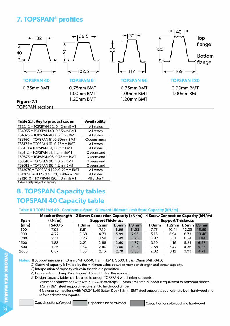
8. ToPSPAn Capacity tables ToPSPAn 40 Capacity table
Capacities for so�wood Capacities for hardwood Capacities for so�wood and hardwood
Member Strength 2 Screw Connection Capacity (kN/m) 4 Screw Connection Capacity (kN/m) Span (kN/m) Support Thickness Support Thickness (mm) TS4075 1.0mm 1.2mm 1.5mm 1.9 mm 1.0mm 1.2mm 1.5mm 1.9 mm 600 7.98 5.51 7.19 8.99 11.93 7.75 10.41 13.09 15.69 900 4.72 3.68 4.79 5.99 7.95 5.16 6.94 8.73 10.461200 2.41 2.76 3.59 4.49 5.96 3.87 5.21 6.54 7.841500 1.83 2.21 2.88 3.60 4.77 3.10 4.16 5.24 6.271800 1.25 1.84 2.40 3.00 3.98 2.58 3.47 4.36 5.232000 0.87 1.65 2.16 2.70 3.58 2.32 3.12 3.93 4.71 Notes: 1) Support members: 1.0mm BMT: G550; 1.2mm BMT: G500; 1.5 & 1.9mm BMT: G450 2) Outward capacity is limited by the minimum value between member strength and screw capacity. 3) Interpolation of capacity values in the table is permitted. 4) Laps are 40mm long. Refer Figure 11.5 and 11.6 in this manual. 5) Design capacity tables can be used to design TOPSPAN with timber supports: 2 fastener connections with M5.5-11x40 BattenZips - 1.5mm BMT steel support is equivalent to so�wood timber, 1.9mm BMT steel support is equivalent to hardwood timber. 4 fastener connections with M5.5-11x40 BattenZips - 1.9mm BMT steel support is equivalent to both hardwood and so�wood timber supports.
Table 8.1 TOPSPAN 40 - Continuous Span - Outward Ultimate Limit State Capacity (kN/m)
117
32
96
102.5
36.5
61
169
40
120
75
32
40
Top flange
Bottomflange
ToPSPAn 40 ToPSPAn 61 ToPSPAn 96 ToPSPAn 120
0.75mm BMt 0.75mm BMt 0.75mm BMt 0.90mm BMt 1.00mm BMt 1.00mm BMt 1.00mm BMt 1.20mm BMt 1.20mm BMt
7. ToPSPAn® profiles
Figure 7.1topspan sections
Table 2.1: Key to product codes Availability TS2242 = TOPSPAN 22, 0.42mm BMT All statesTS4055 = TOPSPAN 40, 0.55mm BMT All statesTS4075 = TOPSPAN 40, 0.75mm BMT All statesTS6160 = TOPSPAN 61, 0.60mm BMT Queensland#TS6175 = TOPSPAN 61, 0.75mm BMT All statesTS6110 = TOPSPAN 61, 1.0mm BMT All statesTS6112 = TOPSPAN 61, 1.2mm BMT QueenslandTS9675 = TOPSPAN 96, 0.75mm BMT QueenslandTS9610 = TOPSPAN 96, 1.0mm BMT QueenslandTS9612 = TOPSPAN 96, 1.2mm BMT QueenslandTS12070 = TOPSPAN 120, 0.70mm BMT All statesTS12090 = TOPSPAN 120, 0.90mm BMT All statesTS12010 = TOPSPAN 120, 1.0mm BMT All states## Availability subject to enquiry.
cy
clo
nic
ar
ea m
an
ua
l21
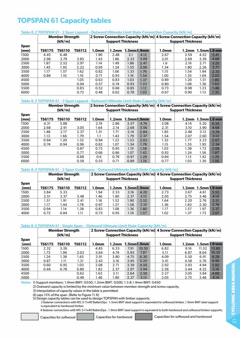
ToPSPAn 61 Capacity tables
Capacities for so�wood Capacities for hardwood Capacities for so�wood and hardwood
Table 8.2 TOPSPAN 61 - 2 Span Lapped - Outward Ultimate Limit State Connection Capacity (kN/m) Member Strength 2 Screw Connection Capacity (kN/m) 4 Screw Connection Capacity (kN/m) (kN/m) Support Thickness Support Thickness Span (mm) TS6175 TS6110 TS6112 1.0mm 1.2mm 1.5mm 1.9mm 1.0mm 1.2mm 1.5mm 1.9 mm1500 4.45 6.48 1.90 2.48 3.1 4.12 2.67 3.59 4.52 5.412000 2.98 3.79 3.85 1.43 1.86 2.33 3.09 2.01 2.69 3.39 4.062500 1.87 2.52 2.97 1.14 1.49 1.86 2.47 1.6 2.16 2.71 3.253000 1.45 1.95 2.22 0.95 1.24 1.55 2.06 1.34 1.80 2.26 2.713500 1.17 1.57 1.62 0.82 1.06 1.33 1.76 1.15 1.54 1.94 2.324000 0.88 1.10 1.16 0.71 0.93 1.16 1.54 1.00 1.35 1.69 2.034500 1.05 0.63 0.83 1.03 1.37 0.89 1.20 1.51 1.805000 0.94 0.57 0.74 0.93 1.23 0.80 1.08 1.36 1.625500 0.83 0.52 0.68 0.85 1.12 0.73 0.98 1.23 1.486000 0.72 0.48 0.62 0.78 1.03 0.67 0.90 1.13 1.35
Table 8.3 TOPSPAN 61 - 3 Span Lapped - Outward Ultimate Limit State Capacity (kN/m) Member Strength 2 Screw Connection Capacity (kN/m) 4 Screw Connection Capacity (kN/m) (kN/m) Support Thickness Support Thickness Span (mm) TS6175 TS6110 TS6112 1.0mm 1.2mm 1.5mm 1.9mm 1.0mm 1.2mm 1.5mm 1.9 mm1500 4.31 5.88 2.19 2.86 3.57 4.74 3.08 4.14 5.20 6.242000 2.68 2.91 3.05 1.64 2.14 2.68 3.56 2.31 3.10 3.90 4.682500 1.48 2.17 2.37 1.31 1.71 2.14 2.84 1.85 2.48 3.12 3.743000 1.13 1.66 1.79 1.1 1.43 1.79 2.37 1.54 2.07 2.60 3.123500 0.94 1.20 1.32 0.94 1.22 1.53 2.03 1.32 1.77 2.23 2.674000 0.74 0.94 0.96 0.82 1.07 1.34 1.78 1.15 1.55 1.95 2.344500 0.87 0.73 0.95 1.19 1.58 1.03 1.38 1.73 2.085000 0.77 0.66 0.86 1.07 1.42 0.92 1.24 1.56 1.875500 0.68 0.6 0.78 0.97 1.29 0.84 1.13 1.42 1.706000 0.58 0.55 0.71 0.89 1.19 0.77 1.03 1.30 1.56
Table 8.4 TOPSPAN 61 - 2 Span Continuous - Outward Ultimate Limit State Capacity (kN/m) Member Strength 2 Screw Connection Capacity (kN/m) 4 Screw Connection Capacity (kN/m) (kN/m) Support Thickness Support Thickness Span (mm) TS6175 TS6110 TS6112 1.0mm 1.2mm 1.5mm 1.9mm 1.0mm 1.2mm 1.5mm 1.9 mm1500 3.84 5.33 1.94 2.53 3.16 4.20 2.73 3.67 4.61 5.522000 2.51 3.37 3.48 1.46 1.90 2.37 3.15 2.05 2.75 3.46 4.142500 1.51 1.91 2.41 1.16 1.52 1.90 2.52 1.64 2.20 2.76 3.313000 1.17 1.44 1.78 0.97 1.27 1.58 2.10 1.36 1.83 2.30 2.763500 0.94 1.14 1.38 0.83 1.08 1.36 1.80 1.17 1.57 1.97 2.374000 0.72 0.84 1.11 0.73 0.95 1.19 1.57 1.02 1.37 1.73 2.07
Table 8.5 TOPSPAN 61 - Single Span - Outward Ultimate Limit State Capacity (kN/m) Member Strength 2 Screw Connection Capacity (kN/m) 4 Screw Connection Capacity (kN/m) (kN/m) Support Thickness Support Thickness Span (mm) TS6175 TS6110 TS6112 1.0mm 1.2mm 1.5mm 1.9mm 1.0mm 1.2mm 1.5mm 1.9 mm1500 2.32 3.26 4.85 6.33 7.91 10.50 6.82 9.16 11.52 13.802000 1.73 1.99 2.03 3.64 4.74 5.93 7.87 5.11 6.87 8.64 10.352500 1.24 1.38 1.65 2.91 3.80 4.75 6.30 4.09 5.50 6.91 8.283000 0.87 1.11 1.31 2.43 3.16 3.95 5.25 3.41 4.58 5.76 6.903500 0.60 0.95 1.03 2.08 2.71 3.39 4.50 2.92 3.93 4.94 5.924000 0.44 0.78 0.80 1.82 2.37 2.97 3.94 2.56 3.44 4.32 5.184500 0.62 1.62 2.11 2.64 3.50 2.27 3.05 3.84 4.605000 0.49 1.46 1.90 2.37 3.15 2.05 2.75 3.46 4.14Notes: 1) Support members: 1.0mm BMT: G550; 1.2mm BMT: G500; 1.5 & 1.9mm BMT: G450 2) Outward capacity is limited by the minimum value between member strength and screw capacity. 3) Interpolation of capacity values in the table is permitted. 4) Laps 15% of the span. (Refer to Figure 11.6) 5) Design capacity tables can be used to design TOPSPAN with timber supports: 2 fastener connections with M5.5-11x40 BattenZips - 1.5mm BMT steel support is equivalent to so�wood timber, 1.9mm BMT steel support is equivalent to hardwood timber. 4 fastener connections with M5.5-11x40 BattenZips - 1.9mm BMT steel support is equivalent to both hardwood and so�wood timber supports.
cy
clo
nic
ar
ea m
an
ua
l22
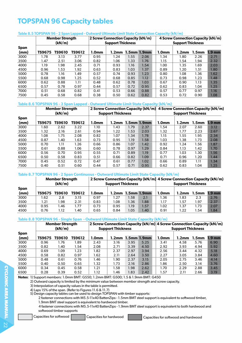
Table 8.5 TOPSPAN 96 - 2 Span Lapped - Outward Ultimate Limit State Connection Capacity (kN/m) Member Strength 2 Screw Connection Capacity (kN/m) 4 Screw Connection Capacity (kN/m) (kN/m) Support Thickness Support ThicknessSpan (mm) TS9675 TS9610 TS9612 1.0mm 1.2mm 1.5mm 1.9mm 1.0mm 1.2mm 1.5mm 1.9 mm3000 1.78 3.13 3.77 0.95 1.24 1.55 2.06 1.34 1.80 2.26 2.713500 1.47 2.51 3.06 0.82 1.06 1.33 1.76 1.15 1.54 1.94 2.324000 1.19 1.98 2.45 0.71 0.93 1.16 1.54 1.00 1.35 1.69 2.034500 0.96 1.53 1.92 0.63 0.83 1.03 1.37 0.89 1.20 1.51 1.805000 0.78 1.16 1.49 0.57 0.74 0.93 1.23 0.80 1.08 1.36 1.625500 0.68 0.98 1.25 0.52 0.68 0.85 1.12 0.73 0.98 1.23 1.486000 0.62 0.88 1.11 0.48 0.62 0.78 1.03 0.67 0.90 1.13 1.356500 0.57 0.78 0.97 0.44 0.57 0.72 0.95 0.62 0.83 1.04 1.257000 0.51 0.68 0.82 0.41 0.53 0.66 0.88 0.57 0.77 0.97 1.167500 0.45 0.58 0.68 0.38 0.50 0.62 0.82 0.53 0.72 0.90 1.08 Table 8.6 TOPSPAN 96 - 3 Span Lapped - Outward Ultimate Limit State Capacity (kN/m) Member Strength 2 Screw Connection Capacity (kN/m) 4 Screw Connection Capacity (kN/m) (kN/m) Support Thickness Support ThicknessSpan (mm) TS9675 TS9610 TS9612 1.0mm 1.2mm 1.5mm 1.9mm 1.0mm 1.2mm 1.5mm 1.9 mm3000 1.60 2.62 3.22 1.10 1.43 1.79 2.37 1.54 2.07 2.60 3.123500 1.32 2.16 2.61 0.94 1.22 1.53 2.03 1.32 1.77 2.23 2.674000 1.08 1.75 2.08 0.82 1.07 1.34 1.78 1.15 1.55 1.95 2.344500 0.87 1.40 1.63 0.73 0.95 1.19 1.58 1.03 1.38 1.73 2.085000 0.70 1.11 1.26 0.66 0.86 1.07 1.42 0.92 1.24 1.56 1.875500 0.61 0.88 1.06 0.60 0.78 0.97 1.29 0.84 1.13 1.42 1.706000 0.56 0.70 0.95 0.55 0.71 0.89 1.19 0.77 1.03 1.30 1.566500 0.50 0.58 0.83 0.51 0.66 0.82 1.09 0.71 0.96 1.20 1.447000 0.45 0.52 0.72 0.47 0.61 0.77 1.02 0.66 0.89 1.11 1.347500 0.40 0.51 0.60 0.44 0.57 0.71 0.95 0.62 0.83 1.04 1.25 Table 8.7 TOPSPAN 96 - 2 Span Continuous - Outward Ultimate Limit State Capacity (kN/m) Member Strength 2 Screw Connection Capacity (kN/m) 4 Screw Connection Capacity (kN/m) (kN/m) Support Thickness Support ThicknessSpan (mm) TS9675 TS9610 TS9612 1.0mm 1.2mm 1.5mm 1.9mm 1.0mm 1.2mm 1.5mm 1.9 mm3000 1.62 2.8 3.15 0.97 1.27 1.58 2.1 1.36 1.83 2.3 2.763500 1.21 1.98 2.31 0.83 1.08 1.36 1.88 1.17 1.57 1.97 2.374000 0.95 1.46 1.77 0.73 0.95 1.19 1.57 1.02 1.37 1.73 2.074500 0.76 1.12 1.40 0.65 0.84 1.05 1.40 0.91 1.22 1.54 1.84 Table 8.8 TOPSPAN 96 - Single Span - Outward Ultimate Limit State Capacity (kN/m) Member Strength 2 Screw Connection Capacity (kN/m) 4 Screw Connection Capacity (kN/m) (kN/m) Support Thickness Support ThicknessSpan (mm) TS9675 TS9610 TS9612 1.0mm 1.2mm 1.5mm 1.9mm 1.0mm 1.2mm 1.5mm 1.9 mm3000 0.96 1.76 1.89 2.43 3.16 3.95 5.25 3.41 4.58 5.76 6.903500 0.82 1.40 1.54 2.08 2.71 3.39 4.50 2.92 3.93 4.94 5.924000 0.69 1.09 1.23 1.82 2.37 2.97 3.94 2.56 3.44 4.32 5.184500 0.58 0.82 0.97 1.62 2.11 2.64 3.50 2.27 3.05 3.84 4.605000 0.48 0.61 0.76 1.46 1.90 2.37 3.15 2.05 2.75 3.46 4.145500 0.40 0.50 0.65 1.32 1.73 2.16 2.86 1.86 2.50 3.14 3.766000 0.34 0.45 0.58 1.21 1.58 1.98 2.62 1.70 2.29 2.88 3.456500 0.28 0.39 0.52 1.12 1.46 1.83 2.42 1.57 2.11 2.66 3.19Notes: 1) Support members: 1.0mm BMT: G550; 1.2mm BMT: G500; 1.5 & 1.9mm BMT: G450 2) Outward capacity is limited by the minimum value between member strength and screw capacity. 3) Interpolation of capacity values in the table is permitted. 4) Laps 15% of the span. (Refer to Figures 11.6 & 11.7) 5) Design capacity tables can be used to design TOPSPAN with timber supports: 2 fastener connections with M5.5-11x40 BattenZips - 1.5mm BMT steel support is equivalent to so�wood timber, 1.9mm BMT steel support is equivalent to hardwood timber. 4 fastener connections with M5.5-11x40 BattenZips - 1.9mm BMT steel support is equivalent to both hardwood and so�wood timber supports
Capacities for so�wood Capacities for hardwood Capacities for so�wood and hardwood
ToPSPAn 96 Capacity tables
cy
clo
nic
ar
ea m
an
ua
l23
Capacities for so�wood Capacities for hardwood Capacities for so�wood and hardwood
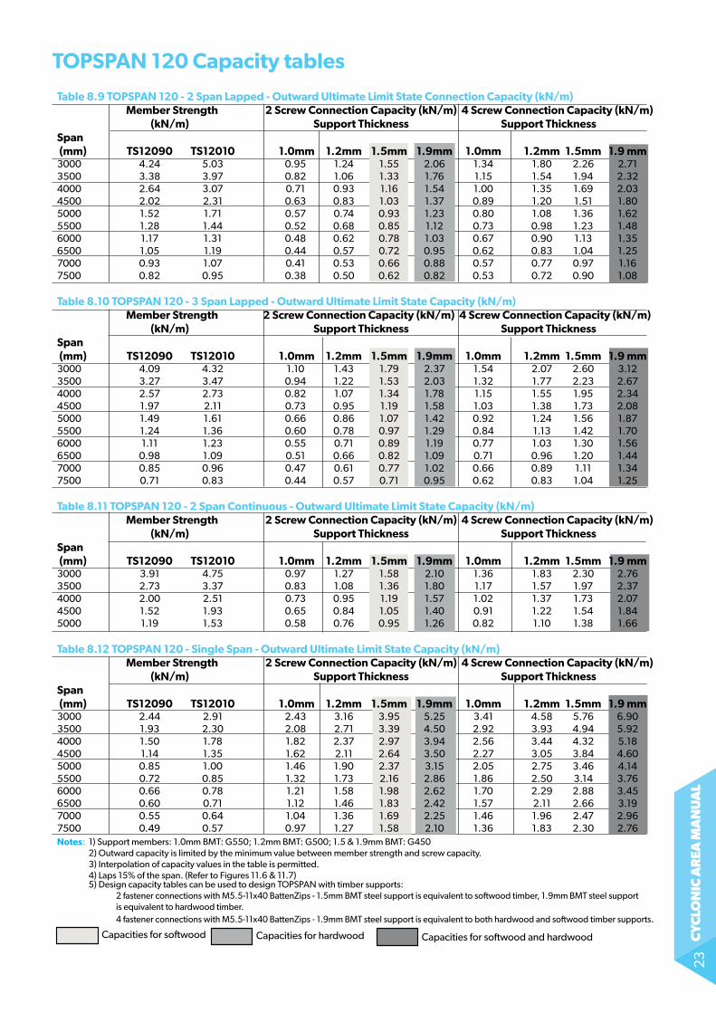
Table 8.9 TOPSPAN 120 - 2 Span Lapped - Outward Ultimate Limit State Connection Capacity (kN/m) Member Strength 2 Screw Connection Capacity (kN/m) 4 Screw Connection Capacity (kN/m) (kN/m) Support Thickness Support ThicknessSpan (mm) TS12090 TS12010 1.0mm 1.2mm 1.5mm 1.9mm 1.0mm 1.2mm 1.5mm 1.9 mm3000 4.24 5.03 0.95 1.24 1.55 2.06 1.34 1.80 2.26 2.713500 3.38 3.97 0.82 1.06 1.33 1.76 1.15 1.54 1.94 2.324000 2.64 3.07 0.71 0.93 1.16 1.54 1.00 1.35 1.69 2.034500 2.02 2.31 0.63 0.83 1.03 1.37 0.89 1.20 1.51 1.805000 1.52 1.71 0.57 0.74 0.93 1.23 0.80 1.08 1.36 1.625500 1.28 1.44 0.52 0.68 0.85 1.12 0.73 0.98 1.23 1.486000 1.17 1.31 0.48 0.62 0.78 1.03 0.67 0.90 1.13 1.356500 1.05 1.19 0.44 0.57 0.72 0.95 0.62 0.83 1.04 1.257000 0.93 1.07 0.41 0.53 0.66 0.88 0.57 0.77 0.97 1.167500 0.82 0.95 0.38 0.50 0.62 0.82 0.53 0.72 0.90 1.08 Table 8.10 TOPSPAN 120 - 3 Span Lapped - Outward Ultimate Limit State Capacity (kN/m) Member Strength 2 Screw Connection Capacity (kN/m) 4 Screw Connection Capacity (kN/m) (kN/m) Support Thickness Support ThicknessSpan (mm) TS12090 TS12010 1.0mm 1.2mm 1.5mm 1.9mm 1.0mm 1.2mm 1.5mm 1.9 mm3000 4.09 4.32 1.10 1.43 1.79 2.37 1.54 2.07 2.60 3.123500 3.27 3.47 0.94 1.22 1.53 2.03 1.32 1.77 2.23 2.674000 2.57 2.73 0.82 1.07 1.34 1.78 1.15 1.55 1.95 2.344500 1.97 2.11 0.73 0.95 1.19 1.58 1.03 1.38 1.73 2.085000 1.49 1.61 0.66 0.86 1.07 1.42 0.92 1.24 1.56 1.875500 1.24 1.36 0.60 0.78 0.97 1.29 0.84 1.13 1.42 1.706000 1.11 1.23 0.55 0.71 0.89 1.19 0.77 1.03 1.30 1.566500 0.98 1.09 0.51 0.66 0.82 1.09 0.71 0.96 1.20 1.447000 0.85 0.96 0.47 0.61 0.77 1.02 0.66 0.89 1.11 1.347500 0.71 0.83 0.44 0.57 0.71 0.95 0.62 0.83 1.04 1.25 Table 8.11 TOPSPAN 120 - 2 Span Continuous - Outward Ultimate Limit State Capacity (kN/m) Member Strength 2 Screw Connection Capacity (kN/m) 4 Screw Connection Capacity (kN/m) (kN/m) Support Thickness Support ThicknessSpan (mm) TS12090 TS12010 1.0mm 1.2mm 1.5mm 1.9mm 1.0mm 1.2mm 1.5mm 1.9 mm3000 3.91 4.75 0.97 1.27 1.58 2.10 1.36 1.83 2.30 2.763500 2.73 3.37 0.83 1.08 1.36 1.80 1.17 1.57 1.97 2.374000 2.00 2.51 0.73 0.95 1.19 1.57 1.02 1.37 1.73 2.074500 1.52 1.93 0.65 0.84 1.05 1.40 0.91 1.22 1.54 1.845000 1.19 1.53 0.58 0.76 0.95 1.26 0.82 1.10 1.38 1.66
Table 8.12 TOPSPAN 120 - Single Span - Outward Ultimate Limit State Capacity (kN/m) Member Strength 2 Screw Connection Capacity (kN/m) 4 Screw Connection Capacity (kN/m) (kN/m) Support Thickness Support ThicknessSpan (mm) TS12090 TS12010 1.0mm 1.2mm 1.5mm 1.9mm 1.0mm 1.2mm 1.5mm 1.9 mm3000 2.44 2.91 2.43 3.16 3.95 5.25 3.41 4.58 5.76 6.903500 1.93 2.30 2.08 2.71 3.39 4.50 2.92 3.93 4.94 5.924000 1.50 1.78 1.82 2.37 2.97 3.94 2.56 3.44 4.32 5.184500 1.14 1.35 1.62 2.11 2.64 3.50 2.27 3.05 3.84 4.605000 0.85 1.00 1.46 1.90 2.37 3.15 2.05 2.75 3.46 4.145500 0.72 0.85 1.32 1.73 2.16 2.86 1.86 2.50 3.14 3.766000 0.66 0.78 1.21 1.58 1.98 2.62 1.70 2.29 2.88 3.456500 0.60 0.71 1.12 1.46 1.83 2.42 1.57 2.11 2.66 3.197000 0.55 0.64 1.04 1.36 1.69 2.25 1.46 1.96 2.47 2.967500 0.49 0.57 0.97 1.27 1.58 2.10 1.36 1.83 2.30 2.76Notes: 1) Support members: 1.0mm BMT: G550; 1.2mm BMT: G500; 1.5 & 1.9mm BMT: G450 2) Outward capacity is limited by the minimum value between member strength and screw capacity. 3) Interpolation of capacity values in the table is permitted. 4) Laps 15% of the span. (Refer to Figures 11.6 & 11.7) 5) Design capacity tables can be used to design TOPSPAN with timber supports: 2 fastener connections with M5.5-11x40 BattenZips - 1.5mm BMT steel support is equivalent to so�wood timber, 1.9mm BMT steel support is equivalent to hardwood timber. 4 fastener connections with M5.5-11x40 BattenZips - 1.9mm BMT steel support is equivalent to both hardwood and so�wood timber supports.
ToPSPAn 120 Capacity tables
cy
clo
nic
ar
ea m
an
ua
l24
X0
0.75 113 0.91 0.054 0.028 1.47531.84 1.322 15.7221.84 21.23 4.661 80.43TS4075
Radius of Gyration
Shearcentre
to centroiddistance
103103
rxry
Product
Shearcentre
to centroiddistance
Xº
99
9TS6112 1.20 234 0.1881.87 0.119 46.49
46.4946.49
3.698 3.951 28.32 22.58 112.70 21.500
Product
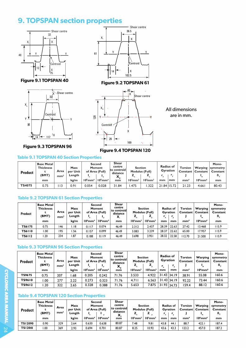
9. ToPSPAn section properties
Table 9.1 ToPSPAn 40 Section Properties
Table 9.2 ToPSPAn 61 Section Properties
0.75 207 1.68 0.205 0.242 3.53371.76 4.922 38.91 55.08 160.6
1.00 277 2.22 0.273 0.323 4.71171.76 6.563 92.22 73.44 160.6
1.20 322 2.65 0.328 0.388 5.65371.76 7.875
31.43 34.19
34.19
34.73
31.4331.93 159.4 88.12 160.6
X0
TS9610
TS9612
Radius of Gyration
Shearcentre
to centroiddistance
103103
rxry
Product
Table 9.3 ToPSPAn 96 Section Properties
Xº
Shearcentre
to centroiddistance
80.87
80.871.00 369 2.93 0.694 0.701 8.25 10.92 43.6 43.3 123.2 457.0 187.2
Product
Table 9.4 ToPSPAn 120 Section Properties
Centroid
Shear centre
4012
0
26169
X°
XX
X X
YYY Y
117 14
32
Xo
Shear centre
Centroid
96
36.5
YY
X
X
Xº
Centroid
102.5
61
14
Shear centre
32
YY
X
X
Xº
Centroid
75
40
12
Shear centre
all dimensions are in mm.
Figure 9.3 ToPSPAn 96
Figure 9.1 ToPSPAn 40 Figure 9.2 ToPSPAn 61
Figure 9.4 ToPSPAn 120
cy
clo
nic
ar
ea m
an
ua
l25
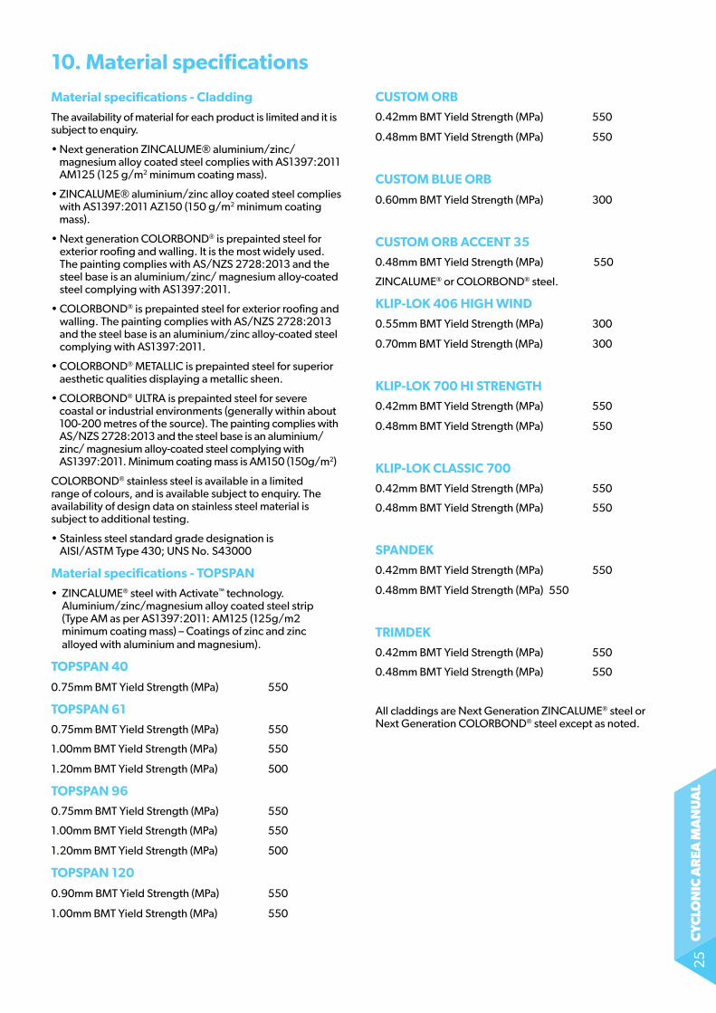
Material specifications - Cladding
the availability of material for each product is limited and it is subject to enquiry.
• Next generation ZINCALUME® aluminium/zinc/magnesium alloy coated steel complies with as1397:2011 aM125 (125 g/m2 minimum coating mass).
• ZINCALUME® aluminium/zinc alloy coated steel complies with as1397:2011 aZ150 (150 g/m2 minimum coating mass).
• Next generation ColorBonD® is prepainted steel for exterior roofing and walling. it is the most widely used. the painting complies with as/nZs 2728:2013 and the steel base is an aluminium/zinc/ magnesium alloy-coated steel complying with as1397:2011.
• ColorBonD® is prepainted steel for exterior roofing and walling. the painting complies with as/nZs 2728:2013 and the steel base is an aluminium/zinc alloy-coated steel complying with as1397:2011.
• ColorBonD® MetalliC is prepainted steel for superior aesthetic qualities displaying a metallic sheen.
• ColorBonD® ULTRA is prepainted steel for severe coastal or industrial environments (generally within about 100-200 metres of the source). the painting complies with as/nZs 2728:2013 and the steel base is an aluminium/zinc/ magnesium alloy-coated steel complying with as1397:2011. Minimum coating mass is aM150 (150g/m2)
ColorBonD® stainless steel is available in a limited range of colours, and is available subject to enquiry. the availability of design data on stainless steel material is subject to additional testing.
• Stainless steel standard grade designation is AISI/ASTM Type 430; UNS No. S43000
Material specifications - ToPSPAn
• ZINCALUME® steel with activate™ technology. Aluminium/zinc/magnesium alloy coated steel strip (type aM as per as1397:2011: aM125 (125g/m2 minimum coating mass) – Coatings of zinc and zinc alloyed with aluminium and magnesium).
ToPSPAn 40
0.75mm BMt Yield strength (Mpa) 550
ToPSPAn 61
0.75mm BMt Yield strength (Mpa) 550
1.00mm BMt Yield strength (Mpa) 550
1.20mm BMt Yield strength (Mpa) 500
ToPSPAn 96
0.75mm BMt Yield strength (Mpa) 550
1.00mm BMt Yield strength (Mpa) 550
1.20mm BMt Yield strength (Mpa) 500
ToPSPAn 120
0.90mm BMt Yield strength (Mpa) 550
1.00mm BMt Yield strength (Mpa) 550
10. Material specifications
CUSToM orB
0.42mm BMt Yield strength (Mpa) 550
0.48mm BMt Yield strength (Mpa) 550
CUSToM BLUe orB
0.60mm BMt Yield strength (Mpa) 300
CUSToM orB ACCenT 35
0.48mm BMt Yield strength (Mpa) 550
ZINCALUME® or ColorBonD® steel.
kLiP-Lok 406 HigH wind
0.55mm BMt Yield strength (Mpa) 300
0.70mm BMt Yield strength (Mpa) 300
kLiP-Lok 700 Hi STrengTH
0.42mm BMt Yield strength (Mpa) 550
0.48mm BMt Yield strength (Mpa) 550
kLiP-Lok CLASSiC 700
0.42mm BMt Yield strength (Mpa) 550
0.48mm BMt Yield strength (Mpa) 550
SPAndek
0.42mm BMt Yield strength (Mpa) 550
0.48mm BMt Yield strength (Mpa) 550
TriMdek
0.42mm BMt Yield strength (Mpa) 550
0.48mm BMt Yield strength (Mpa) 550
all claddings are next generation ZINCALUME® steel or next generation ColorBonD® steel except as noted.
cy
clo
nic
ar
ea m
an
ua
l26
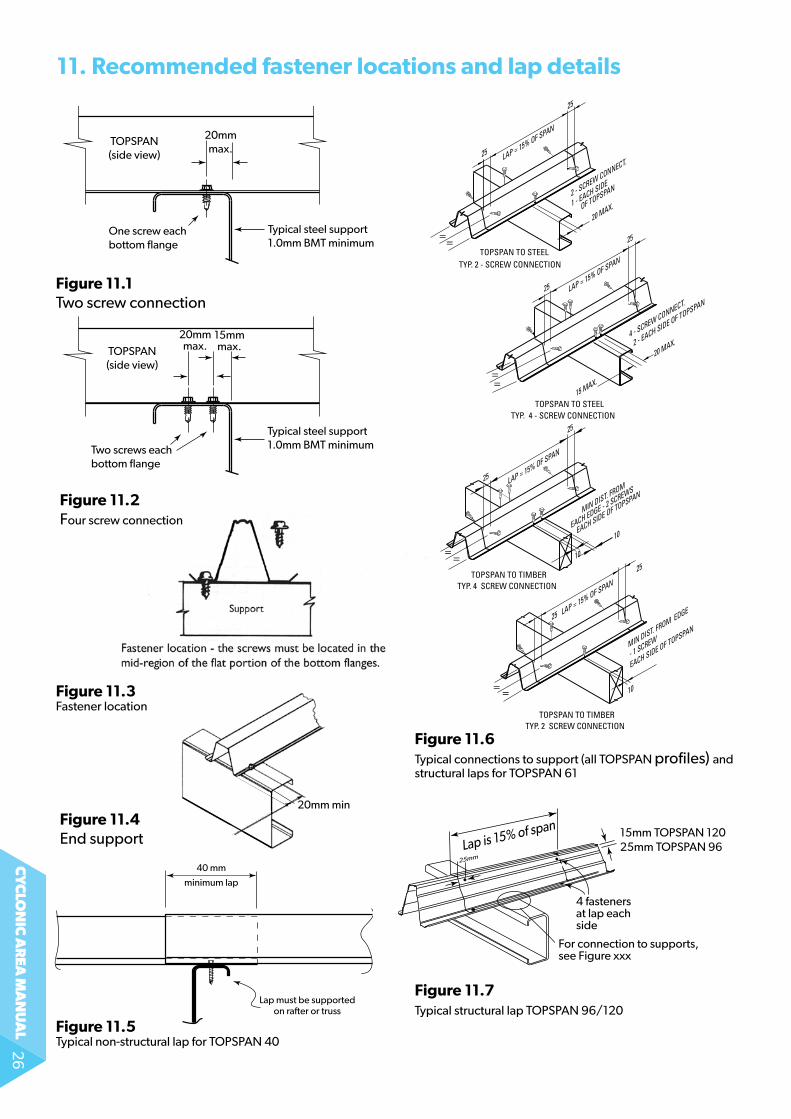
Figure 11.3fastener location
Figure 11.1two screw connection
11. recommended fastener locations and lap details
40 mm
minimum lap
Lap must be supportedon ra�er or truss
Typical non-structural lap
20mm min.Figure 11.4end support
Figure 11.6typical connections to support (all topspan profiles) and structural laps for topspan 61
Figure 11.7typical structural lap topspan 96/120
Figure 11.5typical non-structural lap for topspan 40
TOPSPAN TO TIMBER TYP. 4 SCREW CONNECTION
TOPSPAN TO STEEL TYP. 4 - SCREW CONNECTION
TOPSPAN TO STEEL TYP. 2 - SCREW CONNECTION
TOPSPAN TO TIMBER TYP. 2 SCREW CONNECTION
25
25
15 MAX.
20 MAX.
MIN DIST. FROM
EACH EDGE - 2 SCREWS
EACH SIDE OF TOPSPAN
LAP = 15% OF SPAN
25
25 LAP = 15% OF SPAN
10
10
4 - SCREW CONNECT.
2 - EACH SIDE OF TOPSPAN
25
20 MAX.
LAP = 15% OF SPAN
2 - SCREW CONNECT.
1 - EACH SIDE
OF TOPSPAN
MIN DIST. FROM EDGE
- 1 SCREW
EACH SIDE OF TOPSPAN
25
25 LAP = 15% OF SPAN
10
25
==
= =
==
==
20mmmax.
TOPSPAN(side view)
TOPSPAN(side view)
Typical steel support 1.0mm BMT minimum
One screw each bottom flange
Two screws each bottom flange
Typical steel support 1.0mm BMT minimum
20mmmax.
15mmmax.
Figure 11.2four screw connection
25mm
4 fastenersat lap each side
15mm TOPSPAN 12025mm TOPSPAN 96
For connection to supports, see Figure xxx
Lap is 15% of span
cy
clo
nic
ar
ea m
an
ua
l27
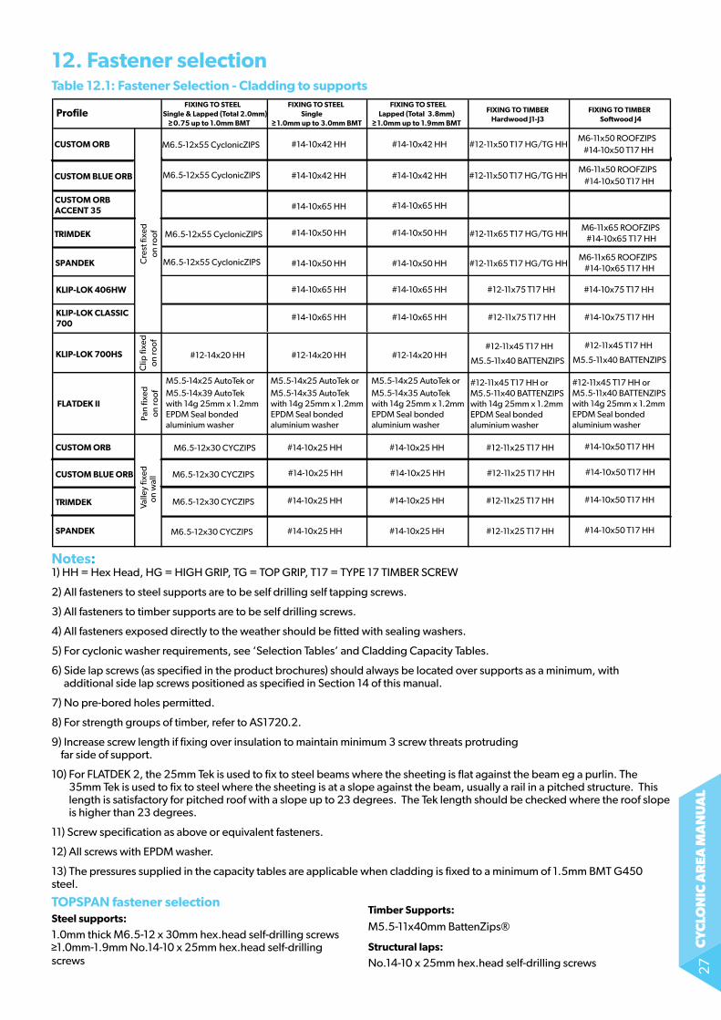
12. fastener selectionTable 12.1: fastener Selection - Cladding to supports
notes:1) HH = Hex Head, Hg = HigH grip, tg = top grip, t17 = tYpe 17 tiMBer sCreW
2) all fasteners to steel supports are to be self drilling self tapping screws.
3) all fasteners to timber supports are to be self drilling screws.
4) all fasteners exposed directly to the weather should be fitted with sealing washers.
5) for cyclonic washer requirements, see ‘selection tables’ and Cladding Capacity tables.
6) side lap screws (as specified in the product brochures) should always be located over supports as a minimum, with additional side lap screws positioned as specified in section 14 of this manual.
7) no pre-bored holes permitted.
8) for strength groups of timber, refer to as1720.2.
9) increase screw length if fixing over insulation to maintain minimum 3 screw threats protruding far side of support.
10) For FLATDEK 2, the 25mm Tek is used to fix to steel beams where the sheeting is flat against the beam eg a purlin. The 35mm Tek is used to fix to steel where the sheeting is at a slope against the beam, usually a rail in a pitched structure. This length is satisfactory for pitched roof with a slope up to 23 degrees. The Tek length should be checked where the roof slope is higher than 23 degrees.
11) screw specification as above or equivalent fasteners.
12) all screws with epDM washer.
13) the pressures supplied in the capacity tables are applicable when cladding is fixed to a minimum of 1.5mm BMt g450 steel.
ToPSPAn fastener selection
ProfileFIXING TO STEEL FIXING TO STEEL FIXING TO STEEL
FIXING TO TIMBER FIXING TO TIMBERSingle & Lapped (Total 2.0mm) Single Lapped (Total 3.8mm)Hardwood J1-J30.75 up to 1.0mm BMT 1.0mm up to 3.0mm BMT 1.0mm up to 1.9mm BMT
CUSTOM ORB #14-10x42 HH #14-10x42 HH #12-11x50 T17 HG/TG HHM6-11x50 ROOFZIPS
CUSTOM BLUE ORB
CUSTOM ORBACCENT 35
M6.5-12x55 CyclonicZIPS#14-10x50 T17 HH
#14-10x42 HH
#14-10x65 HH #14-10x65 HH
#14-10x42 HH #12-11x50 T17 HG/TG HHM6-11x50 ROOFZIPS
M6.5-12x55 CyclonicZIPS#14-10x50 T17 HH
TRIMDEK
#14-10x50 HH #14-10x50 HH #12-11x65 T17 HG/TG HHM6-11x65 ROOFZIPS
SPANDEK
FLATDEK II
M6.5-12x55 CyclonicZIPS#14-10x65 T17 HH
#14-10x50 HH #14-10x50 HH #12-11x65 T17 HG/TG HHM6-11x65 ROOFZIPS
M6.5-12x55 CyclonicZIPS #14-10x65 T17 HH
KLIP-LOK 700HS
KLIP-LOK 406HW
#12-14x20 HH #12-14x20 HH #12-14x20 HH#12-11x45 T17 HH #12-11x45 T17 HH
M5.5-11x40 BATTENZIPS M5.5-11x40 BATTENZIPS
CUSTOM ORB
M6.5-12x30 CYCZIPS
M6.5-12x30 CYCZIPS
M6.5-12x30 CYCZIPS
M6.5-12x30 CYCZIPS
#14-10x25 HH #14-10x25 HH #12-11x25 T17 HH #14-10x50 T17 HH
#14-10x25 HH #14-10x25 HH #12-11x25 T17 HH #14-10x50 T17 HH
#12-11x45 T17 HH orM5.5-11x40 BATTENZIPSwith 14g 25mm x 1.2mm EPDM Seal bondedaluminium washer
#12-11x45 T17 HH orM5.5-11x40 BATTENZIPSwith 14g 25mm x 1.2mm EPDM Seal bondedaluminium washer
#14-10x25 HH #14-10x25 HH #12-11x25 T17 HH #14-10x50 T17 HH
#14-10x25 HH #14-10x25 HH #12-11x25 T17 HH #14-10x50 T17 HH
CUSTOM BLUE ORB
TRIMDEK
SPANDEK
Valle
y fix
ed o
n w
all
Clip
fixe
don
roof
Pan
fixed
on ro
ofC
rest
fixe
don
roof
#14-10x65 HH #14-10x65 HH #12-11x75 T17 HH #14-10x75 T17 HH
KLIP-LOK CLASSIC 700
#14-10x65 HH #14-10x65 HH #12-11x75 T17 HH #14-10x75 T17 HH
Table 16.1 Fastener Selection - Cladding to supports - Cyclonic Areas
M5.5-14x25 AutoTek orM5.5-14x39 AutoTekwith 14g 25mm x 1.2mm EPDM Seal bondedaluminium washer
M5.5-14x25 AutoTek orM5.5-14x35 AutoTekwith 14g 25mm x 1.2mm EPDM Seal bondedaluminium washer
M5.5-14x25 AutoTek orM5.5-14x35 AutoTekwith 14g 25mm x 1.2mm EPDM Seal bondedaluminium washer
Steel supports:
1.0mm thick M6.5-12 x 30mm hex.head self-drilling screws 1.0mm-1.9mm no.14-10 x 25mm hex.head self-drilling
screws
Timber Supports:
M5.5-11x40mm BattenZips®
Structural laps:
no.14-10 x 25mm hex.head self-drilling screws
cy
clo
nic
ar
ea m
an
ua
l28
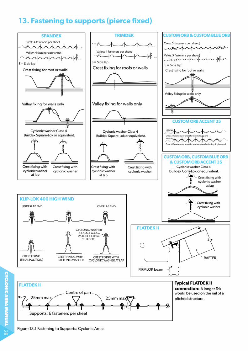
13. fastening to supports (pierce fixed)
figure 13.1 fastening to supports: Cyclonic areas
SPAndek TriMdek
CUSToM orB, CUSToM BLUe orB & CUSToM orB ACCenT 35
CUSToM orB ACCenT 35
CUSToM orB & CUSToM BLUe orB
Crest: 3 fasteners per sheet†
Valley: 3 fasteners per sheet†
Valley: 5 fasteners per sheet†
Crest: 5 fasteners per sheet†
† Fasteners per sheet per supportS = Side-lap
S
S
Crest fixing for roof or walls
Valley fixing for walls only
s = side lap
SValley: 4 fasteners per sheet
Crest: 4 fasteners per sheet
S
Crest: 4 fasteners per sheet
Valley: 4 fasteners per sheet
TRIMDEK
SPANDEK
Number of fasteners depends onwind pressure (see brochure on
this product).
S
S
Crest: 3 fasteners†
Crest: 4 fasteners†
Valley: 3 fasteners†
Valley: 4 fasteners†
† Fasteners per sheet per support. Most common practice is: 3 fasteners for internal spans and 4 fasteners for single and end spans.S = Side-lap
Crest fixing for roof or walls
Valley fixing for walls only
SValley: 4 fasteners per sheet
Crest: 4 fasteners per sheet
S
Crest: 4 fasteners per sheet
Valley: 4 fasteners per sheet
TRIMDEK
SPANDEK
Number of fasteners depends onwind pressure (see brochure on
this product).
s = side laps = side lapCrest fixing for roofs or walls
Valley fixing for walls only
Cyclonic washer Class 4 Buildex Square-Lok or equivalent.
Crest fixing with cyclonic washer
at lap
Crest fixing with cyclonic washer
Cyclonic washer Class 4 Buildex Corri-Lok or equivalent.
Crest fixing with cyclonic washer
at lap
Crest fixing with cyclonic washer
Crest fixing with cyclonic washer
at lap
Crest fixing with cyclonic washer
Cyclonic washer Class 4 Buildex Square-Lok or equivalent.
UNDERLAP END OVERLAP END
CREST FIXING WITH CYCLONIC WASHER AT LAP
CREST FIXING CREST FIXING WITH CYCLONIC WASHER
CYCLONIC WASHERCLASS-4 G300
25 X 33 X 1.0mm'BUILDEX'.
(FINAL POSITION)
UNDERLAP END OVERLAP END
CREST FIXING WITH CYCLONIC WASHER AT LAP
CREST FIXING CREST FIXING WITH CYCLONIC WASHER
CYCLONIC WASHERCLASS-4 G300
25 X 33 X 1.0mm'BUILDEX'.
(FINAL POSITION)
kLiP-Lok 406 HigH wind
fLATdek ii
fLATdek ii
Supports: 6 fasteners per sheet
25mm max. 25mm max.Centre of pan
Typical fLATdek ll connection: A longer Tek would be used on the rail of a pitched structure.
FIRMLOK beam
RAFTER
Crest: 3 fasteners per sheet for internal supports
Crest: 6 fasteners per sheet for end supports (including single spans)
side lap
side lap
cy
clo
nic
ar
ea m
an
ua
l29
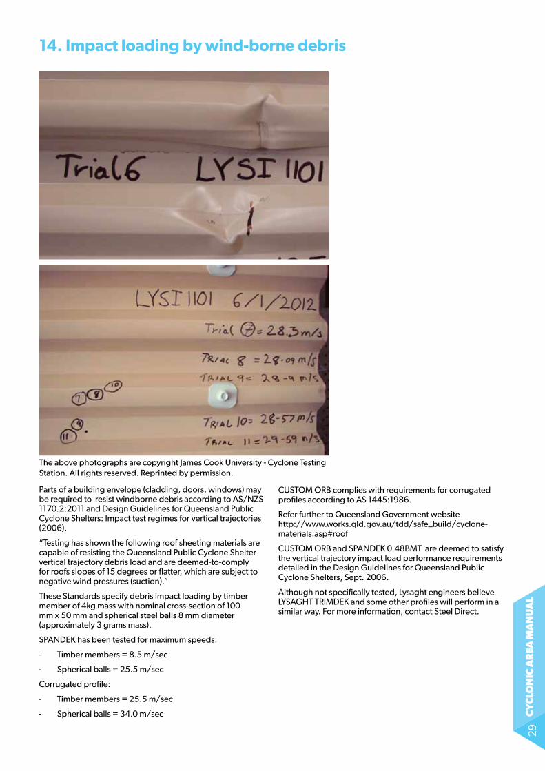
14. impact loading by wind-borne debris
The above photographs are copyright James Cook University - Cyclone Testing station. all rights reserved. reprinted by permission.
parts of a building envelope (cladding, doors, windows) may be required to resist windborne debris according to as/nZs 1170.2:2011 and Design guidelines for Queensland public Cyclone shelters: impact test regimes for vertical trajectories (2006).
“testing has shown the following roof sheeting materials are capable of resisting the Queensland public Cyclone shelter vertical trajectory debris load and are deemed-to-comply for roofs slopes of 15 degrees or flatter, which are subject to negative wind pressures (suction).”
these standards specify debris impact loading by timber member of 4kg mass with nominal cross-section of 100 mm x 50 mm and spherical steel balls 8 mm diameter (approximately 3 grams mass).
spanDeK has been tested for maximum speeds:
- timber members = 8.5 m/sec
- spherical balls = 25.5 m/sec
Corrugated profile:
- timber members = 25.5 m/sec
- spherical balls = 34.0 m/sec
CUSToM oRB complies with requirements for corrugated profiles according to as 1445:1986.
refer further to Queensland government website http://www.works.qld.gov.au/tdd/safe_build/cyclone-materials.asp#roof
CUSToM oRB and spanDeK 0.48BMt are deemed to satisfy the vertical trajectory impact load performance requirements detailed in the Design guidelines for Queensland public Cyclone shelters, sept. 2006.
although not specifically tested, lysaght engineers believe lYsagHt triMDeK and some other profiles will perform in a similar way. for more information, contact steel Direct.

cy
clo
nic
ar
ea m
an
ua
l30
Appendix 1: Topographic classification
notes:
1. an escarpment has one average slope less than 1 in 20 and another average slope greater than 1 in 10.
2. the location of a site on a hill, ridge or escarpment is shown in the illustration above.
3. the average slope (a) is the slope measured by averaging the steepest slope and the least slope through the top half of the hill, ridge or escarpment.
the average slope will not often occur at the actual proposed building site and should be appraised by considering the adjacent topography (see appendix D for the calculation of topography - refer to as 4055).
4. The top-third zone extends for an equal distance, d, either side of the crest of an escarpment as shown above.
The distance ‘d’ is the average horizontal distance measured from the crest of the escarpment to the near top-third zone.
5. The over-top zone of an escarpment is considered to extend to a distance of 5H past the crest of an escarpment.
6. the bottom of a hill, ridge or escarpment is that area at the base of a hill, ridge or escarpment where the average slope is less than 1 in 20, e.g. creek, river valley or flat area.
7. above data is an excerpt from as 4055: 2006.
TOPOGRAPHIC CLASSIFICATION FOR HILLS, RIDGES OR ESCARPMENTS
Average slope (øa)
Hill height (H) below which T1 applies for all sites on the hill, ridge
or escarpment. (m)
Site location (refer to illustration above)
Lower-third zone
(L)
Mid-third zone(M)
Top-third zone(T)
H≤30m H≥30m
Over-top zone (O) for 4H past crest of
escarpments only
<1:10
≥1:10 <1:7.5
≥1:7.5 <1:5
≥1:1.5 <1:3
≥1:3
All H
H< 20
H < 9
—
—
T1 T1 T1
T1
T1
T2
T2 T2
T2 T3
T3 T4
T4 T5T2
T1
T1
T1
T2
T3
T1
T1
T1
T1
T1
Legend:H = Height of hill, ridge or escarpmentL = Lower third of the hill, ridge or escarpmentM = Middle third of the hill, ridge or escarpmentT = Top third of the hill, ridge or escarpmentO = Overtop zone (for escarpment only)d = Average horizontal distance measured from the crest of the escarpment to the near top third zone.
H
d d d d
cy
clo
nic
ar
ea m
an
ua
l31
Appendix 2: Tropical cyclones and wind forces on buildings
Tropical cyclones
tropical cyclones are warm cored wind systems which affect the coastal regions of northern australia. they are formed over warm tropical waters, where the temperature must be >27ºC when severe barometric depressions occur. High speed winds blow spirally inward from all sides to form a roughly circular core or eye which can range in size up to about 50km in diameter. overall, a cyclonic wind system can have a diameter as large as 650km.
the spiralling action is caused by the earth’s rotation and is clockwise in the southern hemisphere, anti-clockwise in the northern hemisphere.
air drawn into the eye of a cyclone is carried vertically by convection and a pumping action generated by high altitude winds. This core activity extends up to 12km above the sea. the air rising in the core of the cyclone carries with it substantial amounts of water vapour which condenses to form heavy cloud and rain in the area of maximum wind force around the core.
the condensing water vapour releases vast amounts of heat energy which is expended enlarging the system. as cyclones extract their energy from the warm water, they dissipate fairly quickly on reaching land, but often not before doing tremendous damage.
Cyclones usually move at speeds of between 2 and 15 m/sec and because of their size, high wind speeds can last for many hours. these winds are of a cyclic nature, causing significant dynamic forces on building components.
these cyclic forces can induce fatigue in roofing materials, their supports and fixings; fatigue which often limits the performance of a component or system. in addition, because of the rotation of the wind system, the wind direction at a particular point can change 180º as the cyclone passes. This requires that building designs should not take shielding into account unless it is roughly equal on all sides.
wind forces on Buildings
Wind creates a number of forces on both internal and external surfaces of a building; forces which must be considered when designing or selecting cladding materials, their fasteners and supports. these forces produce both positive pressure and negative pressure (suction) and their magnitude is affected by the velocity of the wind and the building’s degree of exposure and configuration. the resultant pressures are calculated using as/nZs 1170.2: 2002 structural Design actions part 2: Wind actions.
In cyclonic areas, particular note should be taken of the effects of internal pressures on roof and wall cladding and the importance of local pressure areas.
flying debris is a significant problem in tropical cyclones and there are numerous instances of buildings appearing to stand up to the wind forces until debris broke windows or penetrated wall cladding, thus allowing pressure from the wind to build up inside. the internal pressure, acting with suction on the outside of the roof, was then sufficient to cause failure of the roof system - a sort of “explosion”.
failure of the roofing can be due to inadequate fastening of roof sheeting, in which case the fixings pull out or the sheeting cracks around the fasteners. It can be equally due to inadequate fixing of the roof framing, either the connection between the battens and rafters or the connection of the rafters to the building frame.
irrespective of the reason for the loss of roof, the result is usually catastrophic. Water damage commonly results in the destruction of furniture and furnishings. in addition, framed buildings lose the bracing effect cause by the roof membrane, resulting in the collapse of some external walls.
design wind Speeds
the various conditions which affect the design wind speeds, such as geographic location, terrain category, etc., are to be taken from the ASNZS 1170.2:2002.
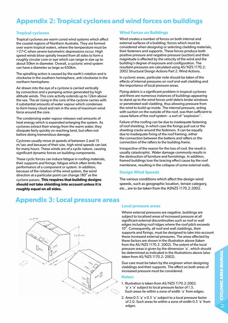
Appendix 3: Local pressure areasLocal pressure areas
Where external pressures are negative, buildings are subject to localised areas of increased pressure at all significant external discontinuities such as roof or wall edges including roof ridges where the roof pitch exceeds 10º. Consequently, all roof and wall claddings, their supports and fixings, must be designed to take into account these increased external pressures. the areas affected by these factors are shown in the illustration above (taken from the as/nZs 1170.2: 2002). the extent of the local pressure areas is given by the dimension ‘a’, which should be determined as indicated in the illustrations above (also taken from AS/NZS 1170.2: 2002).
Due care must be taken by the engineer when designing claddings and their supports. the effect on both areas of increased pressure must be considered.
notes:
1. Illustration is taken from AS/NZS 1170.2:2002. ‘a’ x ‘a’ subject to local pressure factor of 1.5. Such areas lie within a zone of width ‘a’ from edges.
2. area 0.5 ‘a’ x 0.5 ‘a’ subject to a local pressure factor of 2.0. Such areas lie within a zone of width 0.5 ‘a’ from edges.

cy
clo
nic
ar
ea m
an
ua
l32
Product descriptions
all descriptions, specifications, illustrations, drawings, data, dimensions and weights contained in this catalogue, all technical literature and websites containing information from lysaght are approximations only.
they are intended by lysaght to be a general description for information and identification purposes and do not create a sale by description. lysaght reserves the right at any time to:
(a) supply goods with such minor modifications from its drawings and specifications as it sees fit; and
(b) alter specifications shown in its promotional literature to reflect changes made after the date of such publication.
disclaimer, warranties and limitation of liability
this publication is intended to be an aid for all trades and professionals involved with specifying and installing lYsagHt products and not to be a substitute for professional judgement.
terms and conditions of sale available at local lysaght sales offices.
except to the extent to which liability may not lawfully be excluded or limited, Bluescope steel limited will not be under or incur any liability to you for any direct or indirect loss or damage (including, without limitation, consequential loss or damage such as loss of profit or anticipated profit, loss of use, damage to goodwill and loss due to delay) however caused (including, without limitation, breach of contract, negligence and/or breach of statute), which you may suffer or incur in connection with this publication.
© Copyright Bluescope steel limited 10 september, 2014
www.LYsAght.COMTechnical enquires: [email protected] or call 1800 641417LySAGHT, ToPSPAN, KLIP-LoK, SPANDEK, TRIMDEK, CUSToM oRB, CUSToM BLUE oRB, FLATDEK, CoLoRBoND & ZINCALUME are registered trademarks of BlueScope Steel Limited, ABN 16 000 011 058. Teks®, AutoTeks®, Corri-Lok, RoofZips® and Square-Lok® are registered trademarks of ITW Buildex. The lYsagHt ® range of products is made by or for Bluescope steel limited trading as lysaght. 10/9/14 9 3 2 0 0 7 5 0 7 8 1 1 9


