Model CYK Compound Centrifugal Liquid Units Style G Cooling Duty: 300 through 2,500 Tons (1,050 through 8,800 kW) Heating Duty: 10,000 through 40,000 MBH (2,900 through 11,700 kW) Air-cooled Radiators, Brine-chilling and Heat Pump Applications 50 and 60 Hz Utilizing R-134a FORM 160.82-EG1 (712)
Transcript
Model CYK Compound Centrifugal Liquid UnitsStyle G
Cooling Duty:300 through 2,500 Tons (1,050 through 8,800 kW)
Heating Duty:10,000 through 40,000 MBH (2,900 through 11,700 kW)
Air-cooled Radiators, Brine-chilling and Heat Pump Applications50 and 60 Hz
Utilizing R-134a
FORM 160.82-EG1 (712)
2 JOHNSON CONTROLS
FORM 160.82-EG1 (712)
Table of Contents
FORM 160.82-EG1 (712) ....................................................................................................................................................................................... 1Introduction ........................................................................................................................................................................................................... 3Sustainability Focus............................................................................................................................................................................................. 5Equipment Overview ............................................................................................................................................................................................ 7Unit Components ................................................................................................................................................................................................ 10Quantum LX Control Center ...............................................................................................................................................................................11Accessories and Modifications ......................................................................................................................................................................... 14Application Data ................................................................................................................................................................................................. 18Overall Unit Arrangement .................................................................................................................................................................................. 27Compact Nozzle Arrangements ........................................................................................................................................................................ 28Marine Nozzle Arrangements ............................................................................................................................................................................ 34Guide Specifications .......................................................................................................................................................................................... 38SI Metric Conversion .......................................................................................................................................................................................... 44
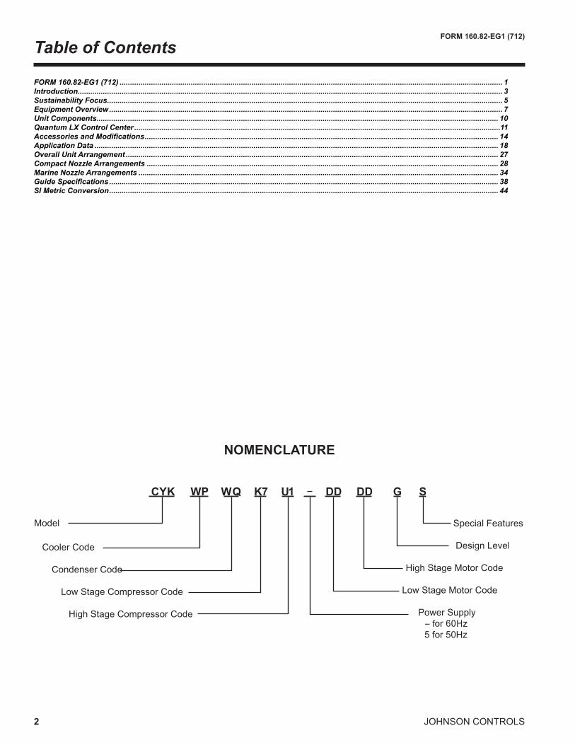
NOMENCLATURE
��� �� �� �� �� �� �� � �
�����
�����������
��������������
�������������������������
�������������������������
��������������
������������������
�����������������������
������������������������������
�������������������������������
�������� �����������������������
FORM 160.82-EG1 (712)
3JOHNSON CONTROLS
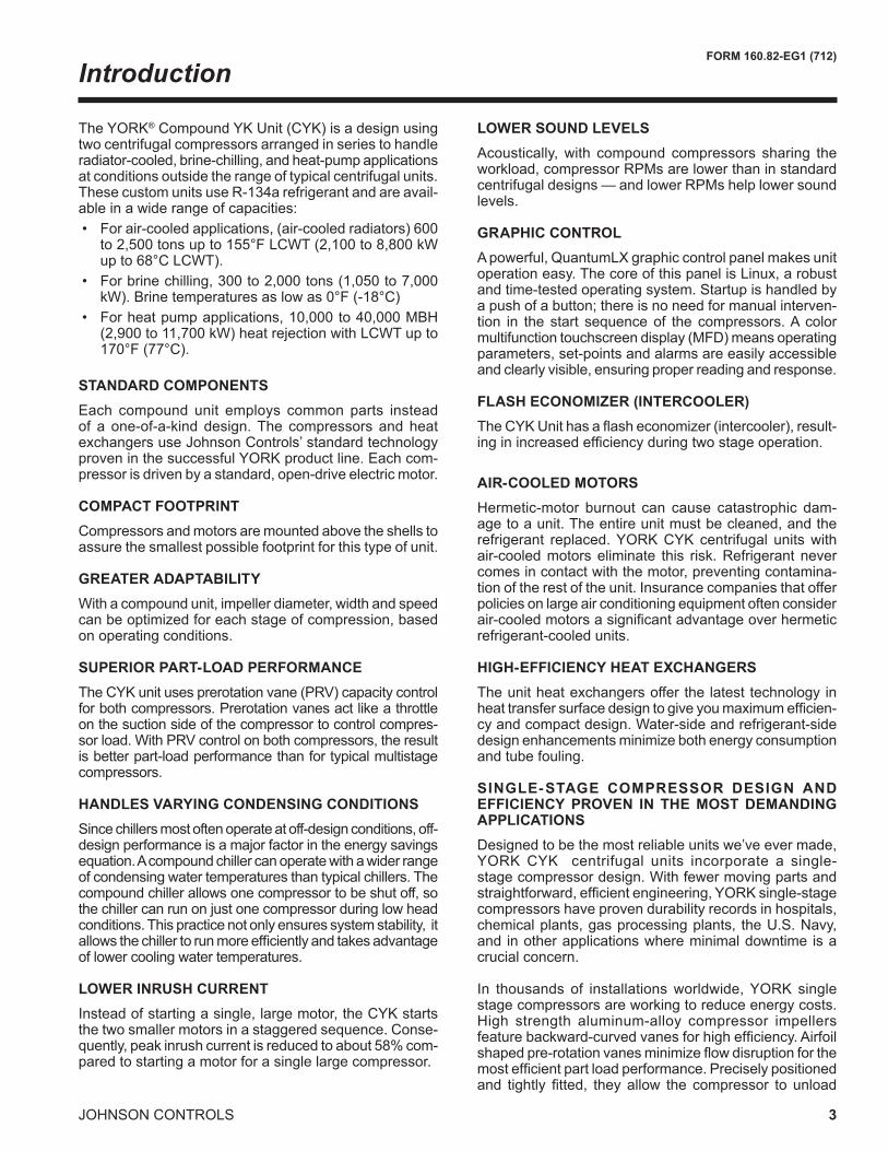
The YORK® Compound YK Unit (CYK) is a design using two centrifugal compressors arranged in series to handle radiator-cooled, brine-chilling, and heat-pump applications at conditions outside the range of typical centrifugal units. These custom units use R-134a refrigerant and are avail-able in a wide range of capacities: • Forair-cooledapplications,(air-cooledradiators)600
STANDARD COMPONENTSEach compound unit employs common parts instead of a one-of-a-kind design.The compressors andheatexchangers use Johnson Controls’ standard technology proven in the successful YORK product line. Each com-pressor is driven by a standard, open-drive electric motor.
COMPACT FOOTPRINTCompressors and motors are mounted above the shells to assure the smallest possible footprint for this type of unit.
GREATER ADAPTABILITYWithacompoundunit,impellerdiameter,widthandspeedcan be optimized for each stage of compression, based on operating conditions.
SUPERIOR PART-LOAD PERFORMANCEThe CYK unit uses prerotation vane (PRV) capacity control forbothcompressors.Prerotationvanesactlikeathrottleon the suction side of the compressor to control compres-sorload.WithPRVcontrolonbothcompressors,theresultis better part-load performance than for typical multistage compressors.
HANDLES VARYING CONDENSING CONDITIONSSince chillers most often operate at off-design conditions, off-designperformanceisamajorfactorintheenergysavingsequation. A compound chiller can operate with a wider range of condensing water temperatures than typical chillers. The compound chiller allows one compressor to be shut off, so thechillercanrunonjustonecompressorduringlowheadconditions. This practice not only ensures system stability, it allowsthechillertorunmoreefficientlyandtakesadvantageof lower cooling water temperatures.
LOWER INRUSH CURRENTInstead of starting a single, large motor, the CYK starts the two smaller motors in a staggered sequence. Conse-quently,peakinrushcurrentisreducedtoabout58%com-pared to starting a motor for a single large compressor.
LOWER SOUND LEVELSAcoustically, with compound compressors sharing the workload,compressorRPMsarelowerthaninstandardcentrifugaldesigns—andlowerRPMshelplowersoundlevels.
GRAPHIC CONTROLApowerful,QuantumLXgraphiccontrolpanelmakesunitoperationeasy.ThecoreofthispanelisLinux,arobustand time-tested operating system. Startup is handled by a push of a button; there is no need for manual interven-tion in the start sequence of the compressors. A color multifunctiontouchscreendisplay(MFD)meansoperatingparameters, set-points and alarms are easily accessible and clearly visible, ensuring proper reading and response.
AIR-COOLED MOTORSHermetic-motor burnout can cause catastrophic dam-age to a unit. The entire unit must be cleaned, and the refrigerant replaced. YORK CYK centrifugal units with air-cooledmotorseliminate this risk.Refrigerantnevercomes in contact with the motor, preventing contamina-tion of the rest of the unit. Insurance companies that offer policies on large air conditioning equipment often consider air-cooledmotorsasignificantadvantageoverhermeticrefrigerant-cooled units.
HIGH-EFFICIENCY HEAT EXCHANGERSThe unit heat exchangers offer the latest technology in heattransfersurfacedesigntogiveyoumaximumefficien-cyandcompactdesign.Water-sideandrefrigerant-sidedesign enhancements minimize both energy consumption and tube fouling.
SINGLE-STAGE COMPRESSOR DESIGN AND EFFICIENCY PROVEN IN THE MOST DEMANDING APPLICATIONSDesignedtobethemostreliableunitswe’veevermade,YORK CYK centrifugal units incorporate a single-stagecompressordesign.Withfewermovingpartsandstraightforward,efficientengineering,YORKsingle-stagecompressors have proven durability records in hospitals, chemical plants, gas processing plants, the U.S. Navy, and in other applications where minimal downtime is a crucial concern.
In thousands of installations worldwide, YORK single stagecompressorsareworkingtoreduceenergycosts.High strength aluminum-alloy compressor impellersfeaturebackward-curvedvanesforhighefficiency.Airfoilshapedpre-rotationvanesminimizeflowdisruptionforthemostefficientpartloadperformance.Preciselypositionedand tightly fitted, theyallow the compressor to unload
Introduction
4 JOHNSON CONTROLS
FORM 160.82-EG1 (712)
smoothlyfrom100%tominimumloadforexcellentopera-tion in all applications.
PRECISION CONTROL OF COMPRESSOR OIL PRES-SUREUsing our expertise in variable-speed drive technology and applications,JohnsonControlshasmovedbeyondthefixedhead and bypass approach of oil pressure control. The old approach only assures oil pressure at the outlet of the pump rather thanat thecompressor,andallowsnoadjustmentduring unit operation. The CYK units feature two variable-speed drive oil pumps, monitoring and providing the right amountofoilflowtoeachcompressoronacontinuousbasis.Variable-speed drive technology reduces oil pump power consumption, running only at the speed required, rather than at full head with a pressure regulating bypass valve. This design also provides sophisticated electronic monitoring and protection of the oil pump electrical supply, ensuring long life and reliable operation of the oil pump motors.
FACTORY PACKAGING REDUCES FIELD LABOR COSTSCYKcentrifugalunitsaredesigned tokeep installationcosts low.Where installation access is not a problem,the unit can be shipped completely or partially pack-aged, requiring minimal piping and wiring to complete the installation.
Theflasheconomizer (intercooler)shipsseparately forassembly with the unit at the time of installation. All piping between the economizer and the unit is prefabricated so no welding is required for installation.
TAKE ADVANTAGE OF COLDER COOLING TOWER WATER TEMPERATURESYORK CYK centrifugal chillers have been designed to takefulladvantageofcoldercoolingtowerwatertempera-tures, which are naturally available during most operating hours. Considerable energy savings are available by let-tingtowerwatertemperaturedrop,ratherthanartificiallyholdingitabove75°F(23.9°C),especiallyatlowload,assome units require.
COMPUTERIZED PERFORMANCE RATINGSEach unit is custom-matched to meet the individual building load and energy requirements. Standard heat exchanger tube bundle sizes and pass arrangements,
are available to provide the best possible match. It is not practical to provide tabulated performance for each com-bination, as the energy requirements at both full and part loadvarysignificantlywitheachheatexchangerandpassarrangement. Computerized ratings are available through eachJohnsonControlssalesoffice.Theseratingscanbetailoredtospecificjobrequirements.
HIGH HEAD APPLICATIONS
• Radiator Cooled: The CYK can be used with air-cooled radiators in a closed loop, designed for areas where cooling towers are not allowed or water is scarce and expensive. The CYK has a huge advantage over low-cost and low-efficiencyair-cooledunits, due tohigh individual compressor capacity and high perfor-mance.
• Thermal Storage: The CYK can be used to produce ice during the night and chilled solution during the day. This unit is well suited in regions with expensive energy cost (demand and usage). The CYK has a huge advantage over 2-stage commercial units or low temperature screw units, based upon the excellent efficiencyatbothduties.
• Turbine Inlet Air Cooling: A CYK can be used to combine both previous applications to improve the performance of gas turbine in regions with a very hot climate and a scarcity of water. The CYK can provide a better initial cost and higher capacities than custom-builtlowtemperaturescrewpackages.
• Low Temperature Process Cooling: The CYK can be applied in industrial applications to produce chilled solutionwithstrictrequirements,likeClass1,GroupD.Div2.Whenusedinthisapplication,theCYKhasadvantages versus custom-built screw packages,based on the excellent efficiency, higher individualcapacity and lower initial cost.
• Heat Pump: The CYK is ideal for use in heat pump applications,supplyingup170°F(77°C)leavingcon-denser water. In this application, the CYK can provide coefficientsofperformanceover4timesgreaterthanwater heaters.More informationonheat pumpap-plications can be found in JohnsonControls FormPUBL-6142.
Introduction
FORM 160.82-EG1 (712)
5JOHNSON CONTROLS
Sustainability Focus
OZONE-DEPLETION POTENTIAL (ODP)
The YORK CYK unit employs one the most environmen-tallyfriendlyrefrigerantsavailabletoday,HFC-134a,withnoOzoneDepletionPotential(ODP)andnophaseoutdatepertheMontrealProtocol.
Ozone is a very small part of the atmosphere, but its presenceisneverthelessvitaltohumanwell-being.Mostozone resides in the upper part of the atmosphere. This region,calledthestratosphere,ismorethan10kilometers(6miles)above theEarth’ssurface.There,about90%of atmospheric ozone is contained in the “ozone layer,” which shields us from harmful ultraviolet radiation from thesun.However,itwasdiscoveredinthemid-1970sthatsome human-produced chemicals could destroy ozone and deplete the ozone layer. The resulting increase in ultraviolet radiation at the Earth’s surface may increase theincidencesofskincancerandeyecataracts.Follow-ing the discovery of this environmental issue, researchers focused on gaining a better understanding of this threat to the ozone layer.
Monitoringstationsshowedthatozone-depletingchemi-cals were steadily increasing in the atmosphere. These trendswere linked to growing production and use ofchemicalslikechlorofluorocarbons(CFCs)forrefrigerationand air conditioning, foam blowing, and industrial clean-ing.Measurementsinthelaboratoryandtheatmospherecharacterized the chemical reactions that were involved in ozone destruction. Computer models employing this information could predict how much ozone depletion was occurring and how much more could occur in the future.
Observations of the ozone layer showed that depletion was indeed occurring. The most severe and most surpris-ing ozone loss was discovered to be recurring in spring-time over Antarctica. The loss in this region is commonly called the “ozone hole” because the ozone depletion is so large and localized. A thinning of the ozone layer also has been observed over other regions of the globe, such astheArcticandnorthernmiddlelatitudes.Theworkofmany scientists throughout the world has provided a basis forbuildingabroadandsolidscientificunderstandingoftheozonedepletionprocess.With this understanding,weknowthatozonedepletionisoccurringandwhy.And,most important,weknowthat ifozone-depletinggaseswere to continue to accumulate in the atmosphere, the result would be more depletion of the ozone layer. In response to the prospect of increasing ozone depletion, the governments of theworld crafted the1987UnitedNationsMontrealProtocolasaglobalmeanstoaddressthis global issue. As a result of the broad compliance with theProtocolanditsAmendmentsandAdjustmentsand,ofgreatsignificance, industry’sdevelopmentof “ozonefriendly” substitutes for the now-controlled chemicals, the total global accumulation of ozone-depleting gases has slowedandbeguntodecrease.Thishasreducedtheriskof further ozone depletion.
HCFC’swereusedasatransitionalrefrigerantastheywerea“LesserEvil”andallowedtheHVACindustrytoquickly transition away fromCFCswhilemaintainingenergyefficiency.Thefactremainsthattheydestroytheozone layer and are legislated to be completely phased out.
TheMontrealProtocoldoesnotextendtoHFC’sastheyhavenoODPnordoesitextendtonaturalrefrigerantsfor the same reason.
The typical usage of the refrigerant, the phase-out status bytheMontrealProtocolandtheglobalusageofrefriger-ant in tons is shown in the table on pg 5.
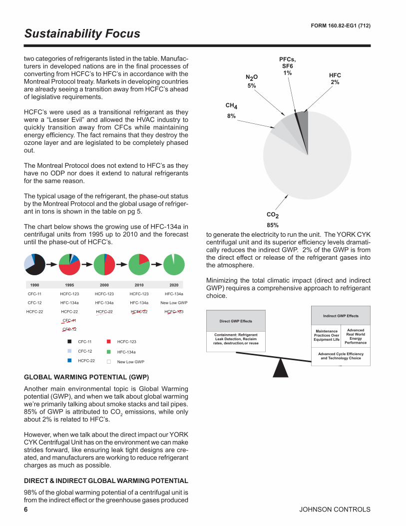
Anothermain environmental topic isGlobalWarmingpotential(GWP),andwhenwetalkaboutglobalwarmingwe’reprimarilytalkingaboutsmokestacksandtailpipes.85%ofGWPisattributedtoCO2 emissions, while only about2%isrelatedtoHFC’s. However,whenwetalkaboutthedirectimpactourYORKCYKCentrifugalUnithasontheenvironmentwecanmakestridesforward,likeensuringleaktightdesignsarecre-ated,andmanufacturersareworkingtoreducerefrigerantcharges as much as possible.
DIRECT & INDIRECT GLOBAL WARMING POTENTIAL
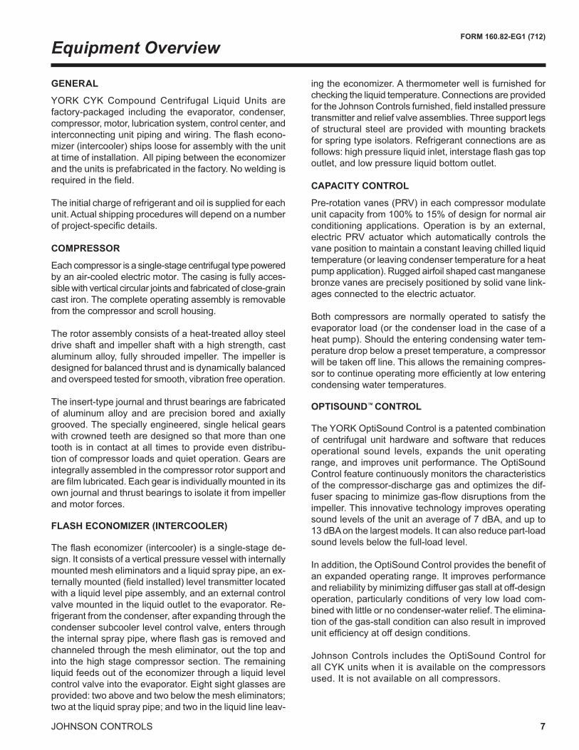
98%oftheglobalwarmingpotentialofacentrifugalunitisfrom the indirect effect or the greenhouse gases produced
to generate the electricity to run the unit. The YORK CYK centrifugalunitanditssuperiorefficiencylevelsdramati-callyreducestheindirectGWP.2%oftheGWPisfromthe direct effect or release of the refrigerant gases into the atmosphere.
Minimizing the total climatic impact (directand indirectGWP)requiresacomprehensiveapproachtorefrigerantchoice.
������
��������
��������
�������
������
����������
����������
���������
��������
������
������
����������
����������
���������
������
����������
����������
�������
������
����������
�������������
��������
������
������
�������
��������
��������
�����������
�������
������ �
������ �
������������ ����
��
,
Sustainability Focus
FORM 160.82-EG1 (712)
7JOHNSON CONTROLS
Equipment Overview
GENERAL
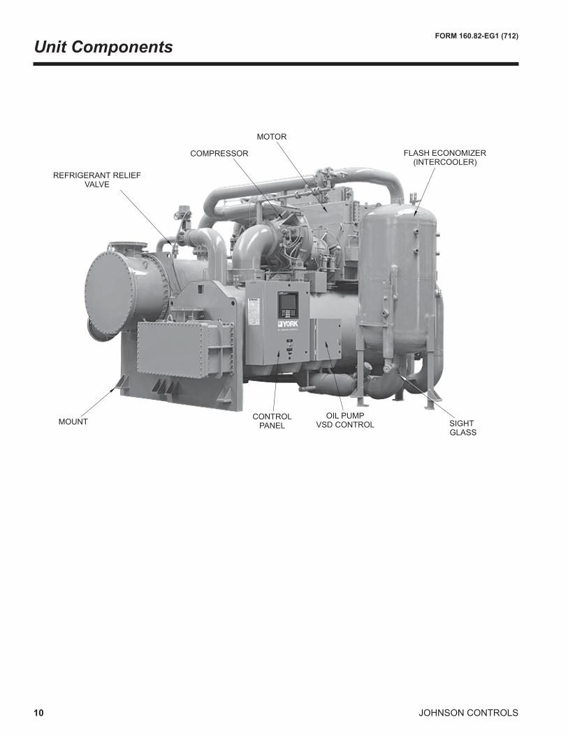
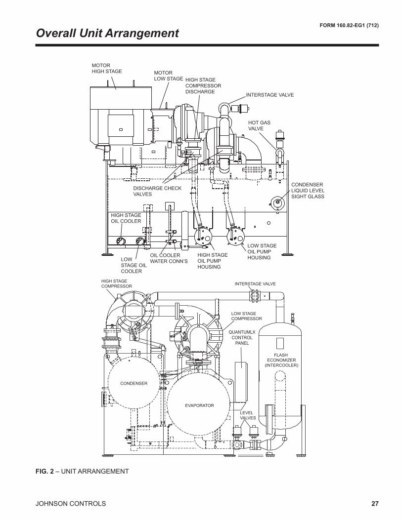
YORK CYK CompoundCentrifugal Liquid Units arefactory-packaged including the evaporator, condenser,compressor, motor, lubrication system, control center, and interconnectingunitpipingandwiring.Theflashecono-mizer (intercooler) ships loose for assembly with the unit at time of installation. All piping between the economizer and the units is prefabricated in the factory. No welding is requiredinthefield.
The initial charge of refrigerant and oil is supplied for each unit. Actual shipping procedures will depend on a number ofproject-specificdetails.
COMPRESSOR
Each compressor is a single-stage centrifugal type powered by an air-cooled electric motor. The casing is fully acces-siblewithverticalcircularjointsandfabricatedofclose-graincast iron. The complete operating assembly is removable from the compressor and scroll housing.
The rotor assembly consists of a heat-treated alloy steel drive shaft and impeller shaft with a high strength, cast aluminum alloy, fully shrouded impeller. The impeller is designed for balanced thrust and is dynamically balanced and overspeed tested for smooth, vibration free operation.
Theinsert-typejournalandthrustbearingsarefabricatedof aluminum alloy and are precision bored and axially grooved. The specially engineered, single helical gears with crowned teeth are designed so that more than one tooth is in contact at all times to provide even distribu-tionofcompressorloadsandquietoperation.Gearsareintegrally assembled in the compressor rotor support and arefilmlubricated.Eachgearisindividuallymountedinitsownjournalandthrustbearingstoisolateitfromimpellerand motor forces.
FLASH ECONOMIZER (INTERCOOLER)
Theflasheconomizer(intercooler)isasingle-stagede-sign. It consists of a vertical pressure vessel with internally mounted mesh eliminators and a liquid spray pipe, an ex-ternallymounted(fieldinstalled)leveltransmitterlocatedwith a liquid level pipe assembly, and an external control valve mounted in the liquid outlet to the evaporator. Re-frigerant from the condenser, after expanding through the condenser subcooler level control valve, enters through theinternalspraypipe,whereflashgasisremovedandchanneled through the mesh eliminator, out the top and into the high stage compressor section. The remaining liquid feeds out of the economizer through a liquid level control valve into the evaporator. Eight sight glasses are provided: two above and two below the mesh eliminators; two at the liquid spray pipe; and two in the liquid line leav-
ing the economizer. A thermometer well is furnished for checkingtheliquidtemperature.ConnectionsareprovidedfortheJohnsonControlsfurnished,fieldinstalledpressuretransmitter and relief valve assemblies. Three support legs ofstructuralsteelareprovidedwithmountingbracketsfor spring type isolators. Refrigerant connections are as follows:highpressureliquidinlet,interstageflashgastopoutlet, and low pressure liquid bottom outlet.
CAPACITY CONTROL
Pre-rotation vanes (PRV) in each compressor modulate unitcapacityfrom100%to15%ofdesignfornormalairconditioning applications. Operation is by an external, electric PRV actuator which automatically controls the vane position to maintain a constant leaving chilled liquid temperature (or leaving condenser temperature for a heat pump application). Rugged airfoil shaped cast manganese bronzevanesarepreciselypositionedbysolidvanelink-ages connected to the electric actuator.
Bothcompressorsarenormallyoperated tosatisfy theevaporator load (or the condenser load in the case of a heat pump). Should the entering condensing water tem-perature drop below a preset temperature, a compressor willbetakenoffline.Thisallowstheremainingcompres-sortocontinueoperatingmoreefficientlyatlowenteringcondensing water temperatures.
OPTISOUND™ CONTROL
The YORK OptiSound Control is a patented combination of centrifugal unit hardware and software that reduces operational sound levels, expands the unit operating range, and improves unit performance. The OptiSound Control feature continuously monitors the characteristics of the compressor-discharge gas and optimizes the dif-fuserspacingtominimizegas-flowdisruptionsfromtheimpeller. This innovative technology improves operating soundlevelsoftheunitanaverageof7dBA,andupto13dBAonthelargestmodels.Itcanalsoreducepart-loadsound levels below the full-load level.
Inaddition,theOptiSoundControlprovidesthebenefitofan expanded operating range. It improves performance and reliability by minimizing diffuser gas stall at off-design operation, particularly conditions of very low load com-bined with little or no condenser-water relief. The elimina-tion of the gas-stall condition can also result in improved unitefficiencyatoffdesignconditions.
Johnson Controls includes the OptiSound Control for all CYK units when it is available on the compressors used. It is not available on all compressors.
8 JOHNSON CONTROLS
FORM 160.82-EG1 (712)
LUBRICATION SYSTEM
Lubrication oil is force-fed to all bearings, gears androtating surfaces by a variable speed drive pump; which operates prior to startup, and continuously during opera-tion and during coast-down. A gravity-fed oil reservoir is built into the top of each compressor to provide lubrica-tion during coast-down in the event of a power failure.
Dual oil reservoirs, separate from the compressors,containthe2HPsubmersibleoilpumpsand1500wattimmersion-type oil heaters for each compressor. The oil heaters are thermostatically controlled to remove refrigerant from the oil.
A water-cooled oil cooler is provided after each oil pump, with factory installed water piping terminat-ing at the center on the condenser side of the unit. A thermostatically controlled bypass valve maintains the required oil temperature supply from each oil cooler to itscompressor.Oilisfilteredbyexternallymounted,1/2micron,replaceablecartridgeoilfilters,equippedwithservice valves. An automatic oil return system recovers any oil that may have migrated to the evaporator. Oil piping is completely factory installed.
MOTOR DRIVELINE
The compressor motors are open drip-proof, squir-rel cage, induction type constructed to YORK design specifications.60hertzmotorsoperateat3570 rpm.50hertzmotorsoperateat2975rpm.
The openmotor is providedwith aD-flange, and isfactory-mounted to a cast iron adapter mounted on the compressor. This unique design allows the motor to be rigidly coupled to the compressor to provide factory alignment of motor and compressor shafts.
Motordriveshaftisdirectlyconnectedtothecompres-sor shaft with a flexible disc coupling. Coupling hasall metal construction with no wearing parts to assure long life, and no lubrication requirements to provide low maintenance.
Alarge,steelterminalboxwithgasketedfrontaccesscoverisprovidedoneachmotorforfield-connectedcon-duit. There are six terminals (three for medium voltage) brought through the motor casing into the terminal box. Jumpers are furnished for three-lead types of starting. Motorterminallugsarenotfurnished.
HEAT EXCHANGERS
Shells
Evaporator and condenser shells are fabricated from rolled carbon steel plates with fusion welded seams. Carbon steel tube sheets, drilled and reamed to accom-modate the tubes, are welded to the end of each shell. Intermediate tube supports are fabricated from carbon steel plates, drilled and reamed to eliminate sharp edges, and spaced no more than four feet apart. The refrigerant side of each shell is designed, tested, and stampedinaccordancewithASMEBoilerandPressureVesselCode,SectionVIII–DivisionI.
Tubes
Heatexchangertubesarestate-of-the-art,high-efficien-cy, externally and internally enhanced type to provide optimum performance. Tubes in both the evaporator and condenser are 3/4” or 1”O.D. copper alloy andutilizethe“skip-fin”design,providingasmoothinternaland external surface at each intermediate tube support. Thisprovidesextrawallthickness(uptotwiceasthick)andnon-workhardenedcopperatthesupportlocation,extending the life of the heat exchangers. Each tube is rollerexpandedintothetubesheetsprovidingaleak-proof seal, and is individually replaceable.
Evaporator
Theevaporatorisashellandtube,floodedtypeheatexchanger. A distributor trough provides uniform distri-bution of refrigerant over the entire shell length to yield optimumheattransfer.Mesheliminatorsorbafflesarelocated above the tube bundle to prevent liquid refriger-antcarryoverintothecompressor.A1.5”(38mm)liquidlevel sight glass is conveniently located on the side of the shell to aid in determining proper refrigerant charge. The evaporator shell contains a dual refrigerant relief valvearrangementsettopressuresupto235psig(16.2barg). A 1” refrigerant charging valve is provided.
Condenser
The condenser is a shell and tube type, with discharge gasbafflestopreventdirecthighvelocityimpingementon the tubes.Thebafflesarealsoused todistributetherefrigerantgasflowproperlyformostefficientheattransfer. An integral sub-cooler is located at the bot-tom of the condenser shell providing highly effective liquid refrigerant sub-cooling to provide the highest cycleefficiency.Thecondensercontainsdualrefriger-antreliefvalvesthatcanbesettopressuresupto350psig (24.1 barg).
Equipment Overview
FORM 160.82-EG1 (712)
9JOHNSON CONTROLS
WATER BOXES
The removable water boxes are fabricated of steel. The designworkingpressure is150psig (10.3barg)andthe boxes are tested at 225 psig (15.5 barg). Integral steelwaterbafflesarelocatedandweldedwithinthewater box to provide the required pass arrangements. Stub-outwaternozzleconnectionswithANSI/AWWAC-606groovesareweldedtothewaterboxes.ThesenozzleconnectionsaresuitableforANSI/AWWAC-606couplings,weldingorflanges,andarecappedforship-ment. Plugged 3/4” drain and vent connections areprovided in each water box.
WATER FLOW SWITCHES
Thermaltypewaterflowswitchesarefactorymountedin the chilled and condenser water nozzles, and are factorywiredtothecontrolpanel.Thesesolidstateflowsensors have a small internal heating element. They use thecoolingeffectoftheflowingfluidtosensewhenanadequateflowratehasbeenestablished.Thesealedsensorprobeis316stainlesssteel,whichissuitedtoveryhighworkingpressures.
ZERO LOAD HOT GAS BYPASS
Sizedforoperationto0%evaporator loadtopreventnuisance shutdowns due to low load conditions, and critical industrial and process applications.
LOW INLET CONDENSER WATER CAPABILITY
The CYK Compound unit incorporates a control strategy that allows a compressor to shut down automatically when two-compressor operation is no longer required. This allows the unit to take advantage of low-inletcondenser water temperatures to reduce energy con-sumption.
The unit is provided with four vibration isolation mounts consisting of 1” (25.4mm) thick neoprene isolationpadsforfieldmountingunderthesteelmountingpadslocatedonthetubesheetsandthreepadsfortheflasheconomizer (intercooler).
REFRIGERANT CONTAINMENT
The standard unit has been designed as a complete andcompactfactory-packagedunitexceptfortheflasheconomizer. The piping between the economizer and the main unit is all prefabricated in the factory with stra-tegicallyplacedflanges.Nofieldweldingisnecessarytoattachtheeconomizer.Assuch,ithasminimumjointsfromwhichrefrigerantcan leak.Theentireassemblyhasbeenthoroughlyleaktestedatthefactorypriortoshipment. The CYK unit includes service valves, con-veniently located to facilitate transfer of refrigerant to a remoterefrigerantstorage/recyclingsystem.
PAINT
Exterior surfaces are protected with one coat of Ca-ribbean blue, durable alkyd-modified, vinyl enamel,machinery paint.
SHIPMENT
Protective covering is furnished on the motor, control center,andunit-mountedcontrols.Waternozzlesarecappedwithfittedplasticenclosures.Entireunitispro-tectedwithindustrial-grade,reinforcedshrink-wrappedcovering.Theflasheconomizer(intercooler)isremovedforshipment.Flangedjointsareprovidedandallpipingis prefabricated.
10 JOHNSON CONTROLS
FORM 160.82-EG1 (712)
Unit Components
FORM 160.82-EG1 (712)
11JOHNSON CONTROLS
Quantum LX Control Center
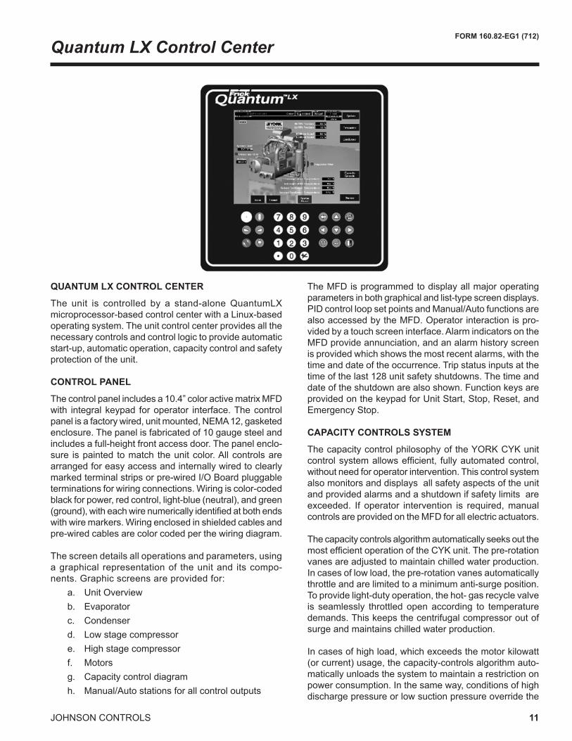
QUANTUM LX CONTROL CENTER
The unit is controlled by a stand-aloneQuantumLXmicroprocessor-basedcontrolcenterwithaLinux-basedoperating system. The unit control center provides all the necessary controls and control logic to provide automatic start-up, automatic operation, capacity control and safety protection of the unit.
CONTROL PANEL
Thecontrolpanelincludesa10.4”coloractivematrixMFDwith integralkeypad foroperator interface.Thecontrolpanelisafactorywired,unitmounted,NEMA12,gasketedenclosure.Thepanelisfabricatedof10gaugesteelandincludes a full-height front access door. The panel enclo-sure is painted to match the unit color. All controls are arranged for easy access and internally wired to clearly markedterminalstripsorpre-wiredI/OBoardpluggableterminationsforwiringconnections.Wiringiscolor-codedblackforpower,redcontrol,light-blue(neutral),andgreen(ground),witheachwirenumericallyidentifiedatbothendswithwiremarkers.Wiringenclosedinshieldedcablesandpre-wired cables are color coded per the wiring diagram.
The screen details all operations and parameters, using a graphical representation of the unit and its compo-nents.Graphicscreensareprovidedfor: a. Unit Overview b. Evaporator c. Condenser d. Lowstagecompressor e. Highstagecompressor f. Motors g. Capacity control diagram h. Manual/Autostationsforallcontroloutputs
TheMFDisprogrammedtodisplayallmajoroperatingparameters in both graphical and list-type screen displays. PIDcontrolloopsetpointsandManual/AutofunctionsarealsoaccessedbytheMFD.Operatorinteractionispro-vided by a touch screen interface. Alarm indicators on the MFDprovideannunciation,andanalarmhistoryscreenis provided which shows the most recent alarms, with the time and date of the occurrence. Trip status inputs at the timeofthelast128unitsafetyshutdowns.Thetimeanddateoftheshutdownarealsoshown.FunctionkeysareprovidedonthekeypadforUnitStart,Stop,Reset,andEmergency Stop.
CAPACITY CONTROLS SYSTEM
The capacity control philosophy of the YORK CYK unit controlsystemallowsefficient, fullyautomatedcontrol,without need for operator intervention. This control system also monitors and displays all safety aspects of the unit and provided alarms and a shutdown if safety limits are exceeded. If operator intervention is required, manual controlsareprovidedontheMFDforallelectricactuators.
ThecapacitycontrolsalgorithmautomaticallyseeksoutthemostefficientoperationoftheCYKunit.Thepre-rotationvanesareadjustedtomaintainchilledwaterproduction.In cases of low load, the pre-rotation vanes automatically throttle and are limited to a minimum anti-surge position. To provide light-duty operation, the hot- gas recycle valve is seamlessly throttled open according to temperature demands.Thiskeepsthecentrifugalcompressoroutofsurge and maintains chilled water production.
Incasesofhighload,whichexceedsthemotorkilowatt(or current) usage, the capacity-controls algorithm auto-matically unloads the system to maintain a restriction on power consumption. In the same way, conditions of high discharge pressure or low suction pressure override the
TheHeatPumpislimitedtoproduceheatontheavail-able heat extracted from the chilled water loop. If there isinsufficientloadonthechilledwaterloop,thenhotgaswillgenerateasmuchheatasitcantomakeupthelackofsourceheatfromthechilledloop.MoreimportantlytheHeatPumpmusthavesufficientloadonthecondenser(heating) side to carry away the heat of compression of the system.TheDesignworkingpressureofthecondenservessel is the limiting factor of the hot water production. On the condenser side of the heat pump, if the load is less than the heat of compression load plus the refrigeration effect, the system will not be able to stay online as the total heat generated in the heat pump is not removed from the heating water loop and will accumulate causing a high pressure shutdown.
HeatPumpmodeandUnit/HeatRecoverycapacitycon-trols operation are mutually exclusive operational modes. The Unit mode produces cold water at setpoint, and any hotwaterrecoveredsimplyabenefit.Theinverseisalsotrue.WhicheverlimitationisreachedfirstbecomesthelimitingfactorandtheHeatPumpwillunloadbasedonlow water temperature or high discharge pressure. There are also limitations on the lift of the single stage centrifugal compressor if the chilled water loop gets too low, which will result in wide-open vane surge if exceeded.
Security access to prevent unauthorized change of set-points, to allow local or remote control of the unit, and to allow manual operation of the pre-rotation vanes and oil pump.AccessisthroughIDandpasswordrecognition,whichisdefinedbythreedifferentlevelsofusercompe-tence: operator, service and factory.
Over-Current Protection
A fused connection through a transformer on the Vari-able Speed Oil Pump Panel to provide individual over-current protected power for all controls.
PLANT MANAGEMENT/CONTROL SYSTEM INTER-FACE:
Ethernet is the preferred LAN (LocalAreaNetwork)betweenLocalUnitControlPanels.Ethernetallowsfull
TheQuantumLXcontrolsystemcanbeaccessedremotelyby any internet browser, when it is incorporated into an eth-ernetnetwork.Thisvirtualoperatorinterfaceallowsquickaccess to the units for full remote management without havingtocreateaseparateSCADAorsupervisorycontrol.
All required analog and discrete data for communica-tionswillbearrangedinblocksof16-bitwords.Alldatais available remotely as read only values. The following write-able control signals are available. Remote Start, RemoteStop,RemoteLeavingChilledWaterSetpoint,andRemoteDemandLimitSetpoint.
Available Network ProtocolsAnyprotocol/mediarequirementsnotlistedinTable1mustbe called out on the factory order form.
Available protocols will be implemented with a Johnson Controls eLink module* or RedLion Data Station where applicable:
Check appropriate protocol and include this docu-ment attached to the Factory Order Form.
All communication interface wiring and hardware, which is required external to the unit control panel, will be sup-plied and installed by the electrical installation contractor under another contract.
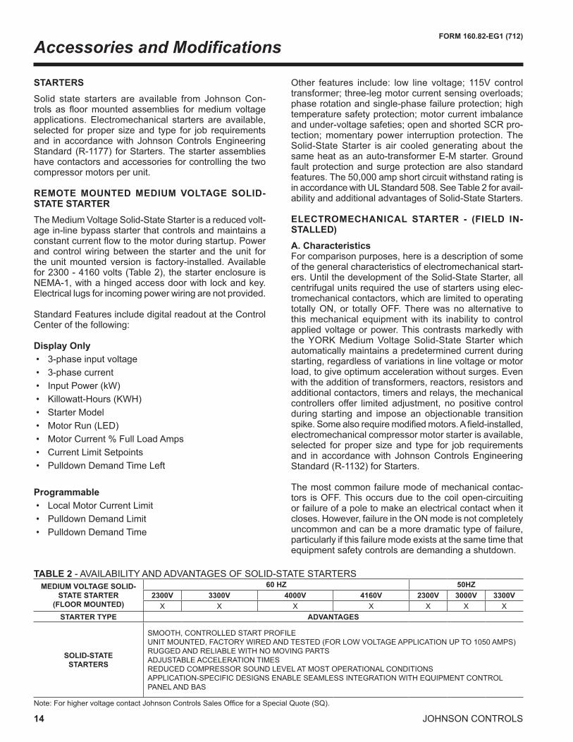
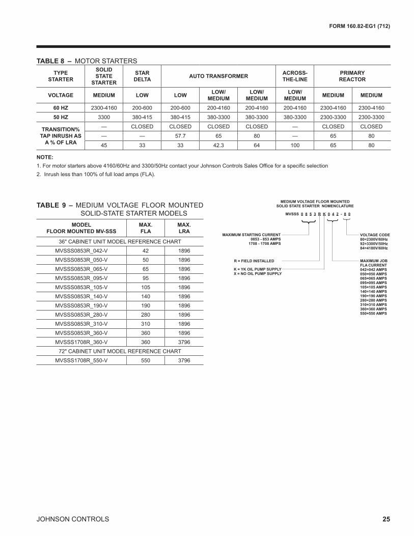
STARTERSSolid state starters are available from Johnson Con-trols as floormountedassemblies formediumvoltageapplications. Electromechanical starters are available, selected for proper sizeand type for job requirementsand in accordance with Johnson Controls Engineering Standard (R-1177) forStarters.Thestarterassemblieshave contactors and accessories for controlling the two compressor motors per unit.
REMOTE MOUNTED MEDIUM VOLTAGE SOLID-STATE STARTER TheMediumVoltageSolid-StateStarterisareducedvolt-age in-line bypass starter that controls and maintains a constantcurrentflowtothemotorduringstartup.Powerand control wiring between the starter and the unit for the unit mounted version is factory-installed. Available for2300-4160volts(Table2),thestarterenclosureisNEMA-1,withahingedaccessdoorwithlockandkey.Electrical lugs for incoming power wiring are not provided.
StandardFeaturesincludedigitalreadoutattheControlCenter of the following:
Other features include: low line voltage; 115V control transformer; three-leg motor current sensing overloads; phase rotation and single-phase failure protection; high temperature safety protection; motor current imbalance and under-voltage safeties; open and shorted SCR pro-tection; momentary power interruption protection. The Solid-State Starter is air cooled generating about the sameheatasanauto-transformerE-Mstarter.Groundfault protection and surge protection are also standard features.The50,000ampshortcircuitwithstandratingisinaccordancewithULStandard508.SeeTable2foravail-ability and additional advantages of Solid-State Starters.
ELECTROMECHANICAL STARTER - (FIELD IN-STALLED)A. Characteristics Forcomparisonpurposes,hereisadescriptionofsomeof the general characteristics of electromechanical start-ers. Until the development of the Solid-State Starter, all centrifugal units required the use of starters using elec-tromechanical contactors, which are limited to operating totallyON, or totallyOFF.Therewasnoalternative tothis mechanical equipment with its inability to control appliedvoltageorpower.ThiscontrastsmarkedlywiththeYORKMediumVoltageSolid-StateStarterwhichautomatically maintains a predetermined current during starting, regardless of variations in line voltage or motor load, to give optimum acceleration without surges. Even with the addition of transformers, reactors, resistors and additional contactors, timers and relays, the mechanical controllers offer limitedadjustment, nopositive controlduring starting and imposeanobjectionable transitionspike.Somealsorequiremodifiedmotors.Afield-installed,electromechanical compressor motor starter is available, selected for proper sizeand type for job requirementsand in accordance with Johnson Controls Engineering Standard (R-1132) for Starters.
The most common failure mode of mechanical contac-tors isOFF.Thisoccursdue to thecoilopen-circuitingorfailureofapoletomakeanelectricalcontactwhenitcloses.However,failureintheONmodeisnotcompletelyuncommon and can be a more dramatic type of failure, particularly if this failure mode exists at the same time that equipment safety controls are demanding a shutdown.
Accessories and Modifications
TABLE 2 -AVAILABILITYANDADVANTAGESOFSOLID-STATESTARTERSMEDIUM VOLTAGE SOLID-
STATE STARTER(FLOOR MOUNTED)
60 HZ 50HZ2300V 3300V 4000V 4160V 2300V 3000V 3300VX X X X X X X
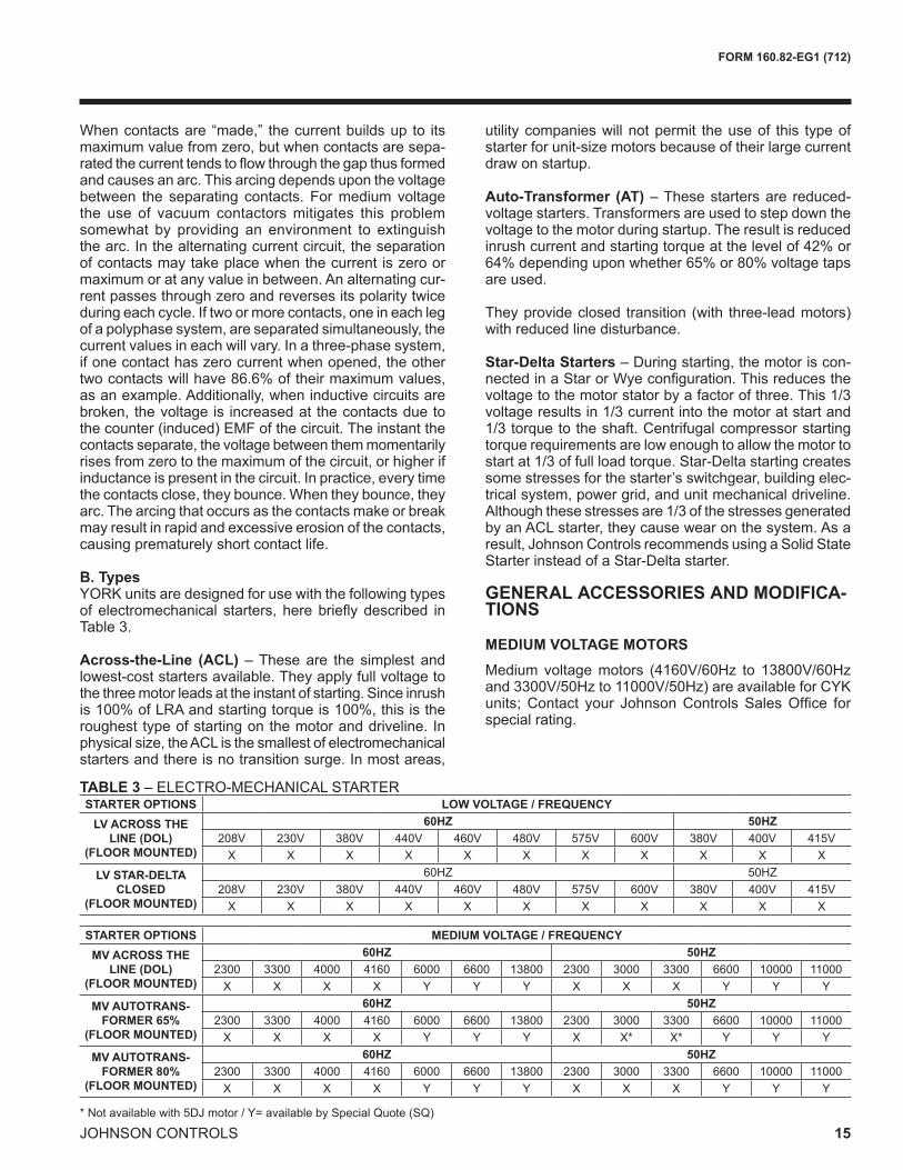
Whencontactsare “made,” thecurrentbuildsup to itsmaximum value from zero, but when contacts are sepa-ratedthecurrenttendstoflowthroughthegapthusformedand causes an arc. This arcing depends upon the voltage between the separating contacts. Formediumvoltagethe use of vacuum contactors mitigates this problem somewhat by providing an environment to extinguish the arc. In the alternating current circuit, the separation ofcontactsmaytakeplacewhenthecurrentiszeroormaximum or at any value in between. An alternating cur-rent passes through zero and reverses its polarity twice during each cycle. If two or more contacts, one in each leg of a polyphase system, are separated simultaneously, the current values in each will vary. In a three-phase system, if one contact has zero current when opened, the other twocontactswillhave86.6%oftheirmaximumvalues,as an example. Additionally, when inductive circuits are broken,thevoltageis increasedatthecontactsduetothecounter(induced)EMFofthecircuit.Theinstantthecontacts separate, the voltage between them momentarily rises from zero to the maximum of the circuit, or higher if inductance is present in the circuit. In practice, every time thecontactsclose,theybounce.Whentheybounce,theyarc.Thearcingthatoccursasthecontactsmakeorbreakmay result in rapid and excessive erosion of the contacts, causing prematurely short contact life.
B. Types YORK units are designed for use with the following types ofelectromechanical starters, herebrieflydescribed inTable 3.
Across-the-Line (ACL) – These are the simplest and lowest-cost starters available. They apply full voltage to the three motor leads at the instant of starting. Since inrush is100%ofLRAandstartingtorqueis100%,thisistheroughest type of starting on the motor and driveline. In physicalsize,theACListhesmallestofelectromechanicalstarters and there is no transition surge. In most areas,
utility companies will not permit the use of this type of starter for unit-size motors because of their large current draw on startup.
Auto-Transformer (AT) – These starters are reduced-voltage starters. Transformers are used to step down the voltage to the motor during startup. The result is reduced inrushcurrentandstartingtorqueatthelevelof42%or64%dependinguponwhether65%or80%voltagetapsare used. They provide closed transition (with three-lead motors) with reduced line disturbance.
Star-Delta Starters–Duringstarting,themotoriscon-nectedinaStarorWyeconfiguration.Thisreducesthevoltagetothemotorstatorbyafactorofthree.This1/3voltageresultsin1/3currentintothemotoratstartand1/3torquetotheshaft.Centrifugalcompressorstartingtorque requirements are low enough to allow the motor to startat1/3offullloadtorque.Star-Deltastartingcreatessome stresses for the starter’s switchgear, building elec-trical system, power grid, and unit mechanical driveline. Althoughthesestressesare1/3ofthestressesgeneratedbyanACLstarter,theycausewearonthesystem.Asaresult, Johnson Controls recommends using a Solid State StarterinsteadofaStar-Deltastarter.
GENERAL ACCESSORIES AND MODIFICA-TIONS
MEDIUM VOLTAGE MOTORS Mediumvoltagemotors (4160V/60Hz to 13800V/60Hzand3300V/50Hzto11000V/50Hz)areavailableforCYKunits;Contact your JohnsonControlsSalesOffice forspecial rating.
TABLE 3–ELECTRO-MECHANICALSTARTERSTARTER OPTIONS LOW VOLTAGE / FREQUENCY
LV ACROSS THE LINE (DOL)
(FLOOR MOUNTED)
60HZ 50HZ208V 230V 380V 440V 460V 480V 575V 600V 380V 400V 415VX X X X X X X X X X X
LV STAR-DELTA CLOSED
(FLOOR MOUNTED)
60HZ 50HZ208V 230V 380V 440V 460V 480V 575V 600V 380V 400V 415VX X X X X X X X X X X
STARTER OPTIONS MEDIUM VOLTAGE / FREQUENCY MV ACROSS THE
LINE (DOL)(FLOOR MOUNTED)
60HZ 50HZ2300 3300 4000 4160 6000 6600 13800 2300 3000 3300 6600 10000 11000X X X X Y Y Y X X X Y Y Y
MV AUTOTRANS-FORMER 65%
(FLOOR MOUNTED)
60HZ 50HZ2300 3300 4000 4160 6000 6600 13800 2300 3000 3300 6600 10000 11000X X X X Y Y Y X X* X* Y Y Y
MV AUTOTRANS-FORMER 80%
(FLOOR MOUNTED)
60HZ 50HZ2300 3300 4000 4160 6000 6600 13800 2300 3000 3300 6600 10000 11000X X X X Y Y Y X X X Y Y Y
16 JOHNSON CONTROLS
FORM 160.82-EG1 (712)
SPECIAL MOTORS ENCLOSURES There are jobapplications, primarily inmanufacturing,comfort cooling plants, and process applications, where moremotorprotectionisrequired.Listedbelowareseveralalternatives.NOTE:UnitcertificationtoULbyathirdpartycould be affected. Contact your Johnson Controls sales officeforaspecificselection.
Weather-Protected Type I Motors (WP-I)–AWeather-Protected Type I motor is an open machine with its ven-tilating passages constructed to prevent the passage of a cylindrical rod ¾” in diameter. This affords protection against intrusion of rodents and some types of debris. These are regularly used in the pulp industry and where grime is present.
Weather-Protected Type II Motors (WP-II)–AWeather-Protected Type II motor has, in addition to the enclosure definedforWeather-ProtectedTypeImotor,ventilatingpassagesatboth intakeandexhaustsoarranged thathigh-velocity air and air-borne particles, blown into the motor, can be discharged without entering the internal ventilating passages leading directly to the electric parts of themachineitself.SpaceheatersarerequiredwithWP-II.
Totally Enclosed Fan-Cooled Motors (TEFC)–TEFCmotors are used where the location is extremely dirty, dusty, or wet, both indoors and outdoors. A totally enclosed fan-cooled unit is enclosed to prevent the free exchange of air between the inside and outside of the case but not sufficientlyenclosedas tobe termedair-tight. It isair-cooled by means of a fully enclosed fan blowing cooling air over the outside of the motor. The fan is externally mounted on the motor shaft.
Totally Enclosed Air-to-Air Cooled (TEAAC) – TEAAC motors are used when the environment is dirty or corro-sive. A TEAAC motor is a totally enclosed motor, cooled by circulating the internal air through an air-to-air heat exchanger.
Totally Enclosed Water-to-Air Cooled (TEWAC) – TEWACmotorsareusedwhentheenvironmentisdirtyorcorrosive, in hazardous areas, or where minimum noise levelsarerequired.ATEWACmotorisatotallyenclosedmachine which is cooled by circulating internal air which, in turn, is cooled by circulating water. It is provided with an internal water-cooled heat exchanger for cooling the internal air and fans, integral with the rotor shaft for cir-culating the internal air.
BAS REMOTE CONTROL Alternatenetworkmediumsandprotocolsmaybeaccom-plished with the addition of a protocol translator gateway. See Table 1 on pg. 9 for additional protocols.
FACTORY INSULATION OF EVAPORATOR Factory-appliedthermalinsulationoftheflexible,closed-cellplastictype,3/4”(19mm)thickisattachedwithvapor-proofcementtotheevaporatorshell,flowchamber,tubesheets, suction connection, and (as necessary) to the aux-iliarytubing.Theflasheconomizer(intercooler)operatesnear room temperature and does not require insulation. Forallotherprojects,optional factory insulationontheflasheconomizer(intercooler)isavailableuponrequest.Not included is the insulation of compact waterboxes and nozzles. This insulation will normally prevent condensation inenvironmentswithrelativehumidifiesupto75%anddrybulbtemperaturesrangingfrom50°to90°F(10°to32.2°C).11/2”(38mm)thickinsulationisalsoavailableforrelativehumidifiesupto90%anddrybulbtemperaturesrangingfrom50°to90°F(10°to32.2°C).Forheatpumpapplications, the condenser can be ordered with optional factory insulation to minimize heat loss to the atmosphere.
WATER FLANGES Four150lb.ANSIraised-faceflangesforcondenserandevaporator water connections are factory-welded to water nozzles.Companionflanges,bolts,nutsandgasketsarenot included.
SPRING ISOLATION MOUNTING Spring isolation mounting is available instead of standard isolation mounting pads when desired. Seven vertically restrained level-adjusting, spring-type vibration isolatorassemblieswith non-skid pads are provided for field-installation. Isolators are designed for one-inch (25 mm) deflection.
MARINE WATER BOXES Marinewaterboxesallowserviceaccessforcleaningoftheheatexchangertubeswithouttheneedtobreakthewaterpiping.Bolted-oncoversarearrangedforconve-nientaccess.ANSI/AWWAC-606nozzleconnectionsarestandard;flangesareoptional.Marinewaterboxesareavailableforcondenserand/orevaporator.
HINGED WATERBOXES Hingedwaterboxesallowfastandsafeserviceaccessforcleaningheatexchangertubes.Hingedwaterboxesonanon-nozzle end give access to the tubes without having todisconnect thewaterpiping.Hingedwaterboxesareavailable forcondenserand/orevaporator forcompactand marine waterboxes. KNOCK-DOWN SHIPMENT Theunitcanbeshippedknockeddownintomajorsub-assemblies (evaporator, condenser, driveline, etc.) as required to rig into tight spaces. This is particularly conve-nient for existing buildings where equipment room access doesnotallowriggingafactory-packagedunit.
Accessories and Modifications
FORM 160.82-EG1 (712)
17JOHNSON CONTROLS
REFRIGERANT ISOLATION VALVES Optional factory-installed isolation valves in the compres-sor discharge line and refrigerant liquid line are available. This allows isolation and storage of the refrigerant charge in the unit condenser during servicing, eliminating time-consuming transfers to remote storage vessels. Bothvalves are positive shut-off, assuring integrity of the stor-age system.
REFRIGERANT STORAGE/RECYCLING SYSTEM Arefrigerantstorage/recyclingsystemisaself-containedpackageconsistingofarefrigerantcompressorwithoilseparator,storagereceiver,water-cooledcondenser,filterdrier and necessary valves and hoses to remove, replace and distill refrigerant. All necessary controls and safety devices are a permanent part of the system.
TUBE AND/OR TUBE SHEET MATERIALS AND/OR WATER BOX COATING Forcondenserand/orevaporatorforprotectionagainstaggressivewater conditions.Alternate cupro-nickel ortitanium tubes can be provided in lieu of standard cop-per. Tube sheets may be of the clad type. Epoxy coating may be applied to water boxes or to tubesheet and water boxes.
HIGHER WATER CIRCUIT DWP Condenserand/orevaporatorwatercircuit(s)DWPhigherthanthestandard150psig(1034barg)DWP.
OUTDOOR AND/OR HAZARDOUS DUTY APPLICA-TIONS Necessaryunit,controlandcontrolcentermodificationsforOutdoor(NEMA-3&4)applicationinlieuofstandardNEMA-1construction.Suitablealternatesurfaceprepara-tion and protective coating systems also available.
UNIT PERFORMANCE TEST VariousoperationalconditionscanbeofferedforFactoryPerformance Test. Please contact your local Johnson Controls Sales Representative for additional details. In caseofFieldPerformanceTest,refertothePUBL-6286andForm160.82-TD1.
18 JOHNSON CONTROLS
FORM 160.82-EG1 (712)
Application Data
The following discussion is a user’s guide in the applica-tion and installation of CYK units to ensure the reliable, trouble-free life for which this equipment was designed. Whilethisguideisdirectedtowardsnormal,water-chillingapplications, the Johnson Controls sales repre sentative can provide complete recommendations on other types ofapplications.IfthisisaHeatPumpapplication,refertoForm160.00-AG1,ApplicationGuideforLargeCapacityWater-to-WaterHeatPumpsforCentralizedPlants.
LOCATION
CYK units are virtually vibration free and may generally be located at any level in a building where the construction will support the total system operating weight.
Theunitsitemustbeafloor,mountingpadorfoundationwhichislevelwithin1/4”(6.4mm)andcapableofsup-porting the operating weight of the unit.
Sufficientclearancetopermitnormalserviceandmain-tenanceworkshouldbeprovidedallaroundandabovethe unit. Additional space should be provided at one end of the unit to permit cleaning of evaporator and condenser tubes as required. A doorway or other properly located opening may be used.
The unit should be installed in an indoor location where temperaturesrangefrom40°Fto104°F(4.4°Cto40°C).
WATER CIRCUITS
Flow Rate – Fornormalwaterchillingduty,evaporatorandcondenserflowratesarepermittedatwatervelocitylevelsintheheatexchangerstubesofbetween3.0ft/secand12ft/sec(0.91m/sand3.66m/s).Variableflowap-plications are possible, and initial unit selections should bemadeaccordinglytoallowproperrangeofflowwhilemaintaining the minimum velocity noted above. Variable flowinthecondenserisnotrecommended,asitgenerallyraisestheenergyconsumptionofthesystembykeepingthe condenser pressure high in the unit. Additionally, the rate of fouling in the condenser will increase at lower water velocitiesassociatedwith variable flow, raisingsystemmaintenance costs. Cooling towers typically have narrow rangesofoperationwith respect toflowrates,andwillbemoreeffectivewithfulldesignflow.ContactJohnsonControlsSalesforspecificflowlimits.
Water Quality – The practical and economical applica-tion of liquid units requires that the quality of the water supply for the condenser and evaporator be analyzed by awatertreatmentspecialist.Waterqualitymayaffecttheperformance of any unit through corrosion, deposition of heat-resistant scale, sedimentation or organic growth. These will degrade unit performance and increase operat-ing and maintenance costs. Normally, performance may
be maintained by corrective water treatment and periodic cleaning of tubes. If water conditions exist which cannot be corrected by proper water treatment, it may be nec essary toprovidealargerallowanceforfouling,and/ortospecifyspecial materials of construction.
General Piping – All chilled water and condenser water piping should be designed and installed in accordance with accepted piping practice. Chilled water and con denser water pumps should be located to discharge through theunittoassurepositivepressureandflowthroughtheunit.Pipingshouldincludeoffsetstoprovideflexibilityandshould be arranged to prevent drainage of water from the evaporator and condenser when the pumps are shut off. Piping should be adequately supported and braced independently of the unit to avoid the imposition of strain onunitcomponents.Hangersmustallowforalignmentof the pipe. Isolators in the piping and in the hangers are highly desirable in achiev ing sound and vibration control.
Convenience Considerations – To facilitate the performanceof routinemaintenancework,someorallof the followingstepsmaybe takenby thepurchaser.Evaporator and condenser water boxes are equipped with plugged vent and drain connections. If desired, vent and drain valves may be installed with or without piping toanopendrain.Pressuregaugeswithstopcocksandstop valves may be installed in the inlets and outlets of the condenser and chilled water line as close as possible to the unit. An overhead monorail or beam may be used to facilitate servicing.
Connections – Thestandardunit isdesigned for150psig (1034 kPA) designworking pressure in both thechilled water and condenser water circuits. The connec-tions (water nozzles) to these circuits are furnished with groovesforANSI/AWWAC-606couplings.Pipingshouldbe arranged for ease of disassembly at the unit for tube cleaning. All water piping should be thoroughly cleaned ofalldirtanddebrisbeforefinalconnectionsaremadeto the unit.
Condenser Water Strainer – A water strainer of maxi-mum1/8”(3mm)perforatedholesisrecommendedtobefieldinstalledintherefrigerantcondenserwaterinletlineas close as possible to the unit. If located close enough to the unit, the condenser water pump may be protected by the same strainer. The loss or severe reduction of water flowdue to blockage could seriously impair theunit’s performance.
MULTIPLE UNITS
Selection – Many applications requiremultiple unitsto meet the total capacity requirements as well as to provideflexibilityandsomedegreeofprotectionagainst
FORM 160.82-EG1 (712)
19JOHNSON CONTROLS
equipment shutdown. There are several common unit ar-rangements for this type of application. The CYK unit has been designed to be readily adapted to the requirements of these various arrangements.
Parallel Arrangement (Refer to Fig. 1) – Unitsmaybe applied in multiples with chilled and condenser water circuits connected inparallelbetween theunits.Fig.1represents a parallel arrangement with two units. Parallel unit arrangements may consist of equally or unequally sizedunits.Whenmultipleunitsare inoperation, theywill load and unload at equal percentages of design full load for the unit.
Dependingonthenumberofunitsandoperatingchar-acteristics of the units, loading and unloading schemes shouldbedesignedtooptimizetheoverallefficiencyoftheunit plant. It is recommended to use an evaporator by-pass pipingarrangementtobypassfluidaroundevaporatorofany unit which has cycled off at reduced load conditions. It is also recommended to alternate the unit cycling order to equalize unit starts and run hours.
REFRIGERANT RELIEF PIPING
Each unit is equipped with dual pressure relief valves on the condenser, dual relief valves on the evaporator and dualreliefvalvesontheflasheconomizer(intercooler).The dual relief valves are redundant and allow changing of either valve while the unit is fully charged. The purpose ofthereliefvalvesistoquicklyrelieveexcesspressureof the refrigerant charge to the atmosphere, as a safety precaution in theevent of anemergency suchas fire.
They are set to relieve at an internal pressure as noted on the pressure vessel data plate, and are provided in accordancewithASHRAE15safetycodeandASMEorapplicable pressure vessel code.Sized to the requirements of applicable codes, a vent line must run from the relief device to the outside of the build-ing. This refrigerant relief piping must include a cleanable, vertical-leg dirt trap to catch vent-stack condensation.Vent piping must be arranged to avoid im posing a strain onthereliefconnectionandshouldincludeoneflexibleconnection.
SOUND AND VIBRATION CONSIDERATIONS
A CYKunit isnotasourceofobjectionablesoundandvibration in normal air conditioning applica tions. Neoprene isolation mounts are furnished as standard with each unit.Optionallevel-adjustingspringisolatorassembliesdesigned for1” (25mm)staticdeflectionareavailablefrom Johnson Controls.
CYK unit sound pressure level ratings will be furnished on request.
Controlofsoundandvibrationtransmissionmustbetakeninto account in the equipment room construction as well as in the selection and installation of the equip ment.
THERMAL INSULATION
No appreciable operating economy can be achieved by thermallyinsulatingtheunit.However,theunit’scoldsur-faces should be insulated with a vapor barrier insulation sufficienttopreventcondensation.Aunitcanbefactoryinsulatedwith3/4”(19mm)or1-1/2”(38mm)thickinsu-lation, as an option. This insulation will normally pre vent condensation in environments with dry bulb temperatures of50°F to90°F(10°C to32°C)andrelativehumiditiesupto75%[3/4”(19mm)thickness]or90%[1-1/2”(38mm) thickness].Forheatpumpapplicationswhere thecondenseroperatingtemperatureisabove140°F(60°C),thermal insulation is also recommended. The insulation surfaceisflexibleandreasonablyresistanttowear.Itisintended for a unit installed indoors and, therefore, no protective covering of the insulation is usually required. Ifinsulationisappliedtothewaterboxesatthejobsite,it must be removable to permit access to the tubes for routinemaintenance. For heat pumpapplications thecondenser can be ordered with optional factory insulation to minimize heat loss to the atmosphere.
VENTILATION
TheASHRAEStandard15SafetyCodeforMechanicalRefrigeration requires that all machinery rooms be vented to the outdoors using mechanical ventilation by one or more power-driven fans. This standard, plus National FIG. 1 – PARALLELEVAPORATORS
PARALLELCONDENSERS
CONDENSER1
CONDENSER2
EVAPORATOR1
EVAPORATOR2
TEMPERATURE SENSOR FORUNIT CAPACITY CONTROL
THERMOSTAT FOR UNIT CAPACITY CONTROL
20 JOHNSON CONTROLS
FORM 160.82-EG1 (712)
FireProtectionAssociationStandard90A,state,localandanyotherrelatedcodesshouldbereviewedforspecificrequirements. Since the CYK unit mo tor is air-cooled, ven-tilation should allow for the removal of heat from the motor.
Inaddition,theASHRAEStandard15requiresarefriger-ant vapor detector to be employed for all refrigerants. It istobelocatedinanareawhererefrigerantfromaleakwouldbelikelytoconcentrate.Analarmistobeactivatedand the mechanical ventilation started at a value no great-erthantheTLV(ThresholdLimitValue)oftherefrigerant.
ELECTRICAL CONSIDERATIONS
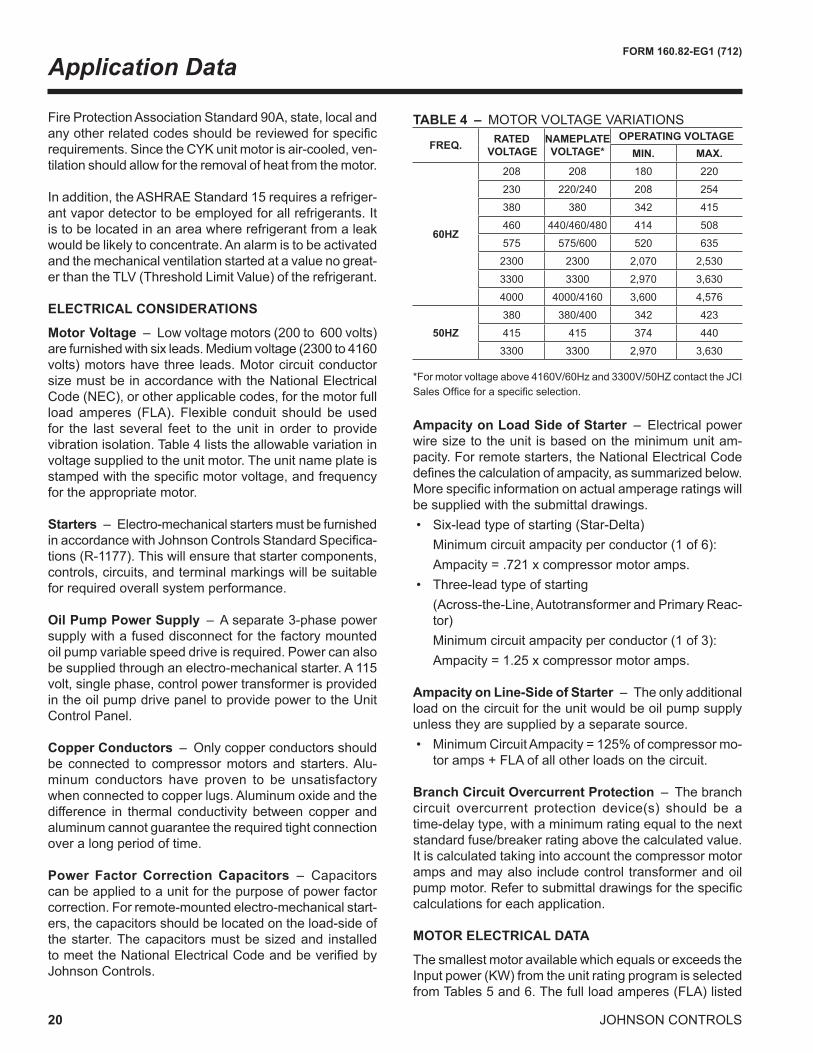
Motor Voltage – Lowvoltagemotors(200to600volts)arefurnishedwithsixleads.Mediumvoltage(2300to4160volts)motorshavethree leads.Motorcircuitconductorsize must be in accord ance with the National Electrical Code (NEC), or other applica ble codes, for the motor full load amperes (FLA). Flexible conduit should be usedfor the last several feet to the unit in order to provide vibration isolation. Table 4 lists the allowable variation in voltage supplied to the unit motor. The unit name plate is stampedwiththespecificmotorvoltage,andfrequencyfor the appropri ate motor.
Starters – Elec tro-mechanical starters must be furnished inaccordancewithJohnsonControlsStandardSpecifica-tions(R-1177).Thiswillensurethatstartercomponents,controls,circuits,andterminalmarkingswillbesuitablefor required overall system performance. Oil Pump Power Supply – A separate 3-phase power supply with a fused disconnect for the factory mounted oil pump variable speed drive is required. Power can also be supplied through an electro-mechanical starter. A 115 volt, single phase, control power transformer is provided in the oil pump drive panel to provide power to the Unit Control Panel.
Copper Conductors – Only copper conductors should be connected to compressor motors and starters. Alu-minum conductors have proven to be un satisfactory when connected to copper lugs. Aluminum oxide and the difference in thermal conductivity be tween copper and aluminum cannot guarantee the re quired tight connection over a long period of time.
Power Factor Correction Capacitors – Capacitors can be applied to a unit for the purpose of power factor correction.Forremote-mountedelectro-mechanicalstart-ers, the ca pacitors should be located on the load-side of the starter. The capacitors must be sized and installed tomeettheNationalElectricalCodeandbeverifiedbyJohnson Controls.
Ampacity on Load Side of Starter – Electrical power wire size to the unit is based on the minimum unit am-pacity.Forremotestarters,theNationalElectricalCodedefinesthecalculationofampacity,assummarizedbelow.Morespecificinformationonactualamperageratingswillbe supplied with the submittal drawings.• Six-leadtypeofstarting(Star-Delta) Minimumcircuitampacityperconductor(1of6): Ampacity=.721xcompressormotoramps.• Three-leadtypeofstarting (Across-the-Line,AutotransformerandPrimaryReac-
Ampacity on Line-Side of Starter – The only additional load on the circuit for the unit would be oil pump supply unless they are sup plied by a separate source.• MinimumCircuitAmpacity=125%ofcompressormo-
toramps+FLAofallotherloadsonthecircuit.
Branch Circuit Overcurrent Protection – The branch circuit overcurrent protection device(s) should be a time-delay type, with a minimum rating equal to the next standardfuse/breakerratingabovethecalculatedvalue.Itiscalculatedtakingintoaccountthecompressormotoramps and may also include control trans former and oil pumpmotor.Refertosubmittaldrawingsforthespecificcalculations for each application.
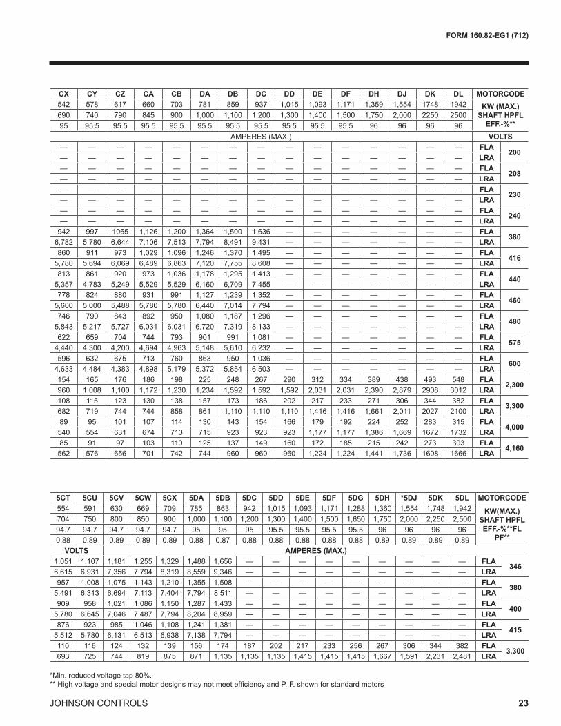
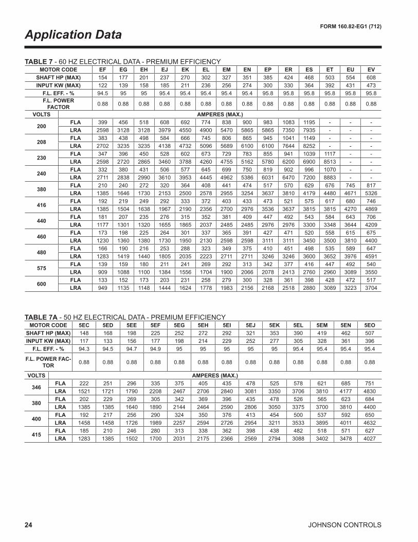
MOTOR ELECTRICAL DATA
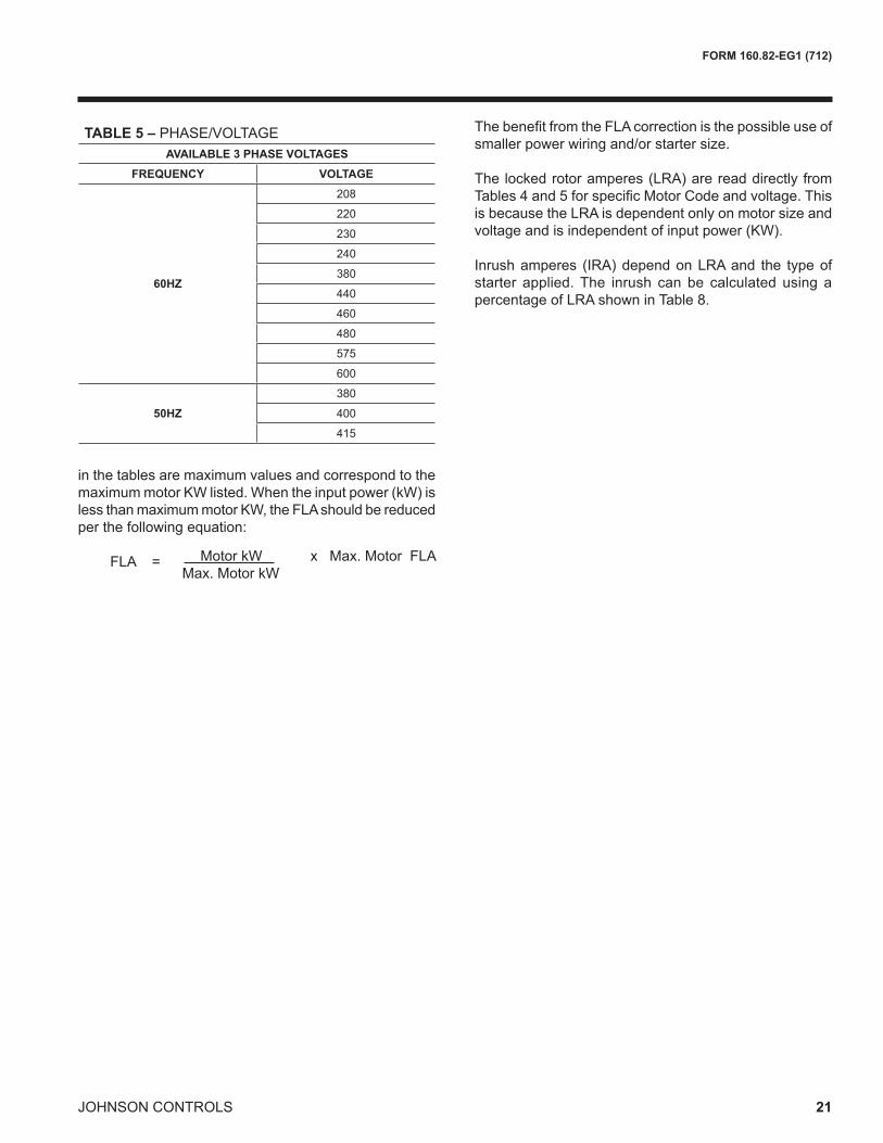
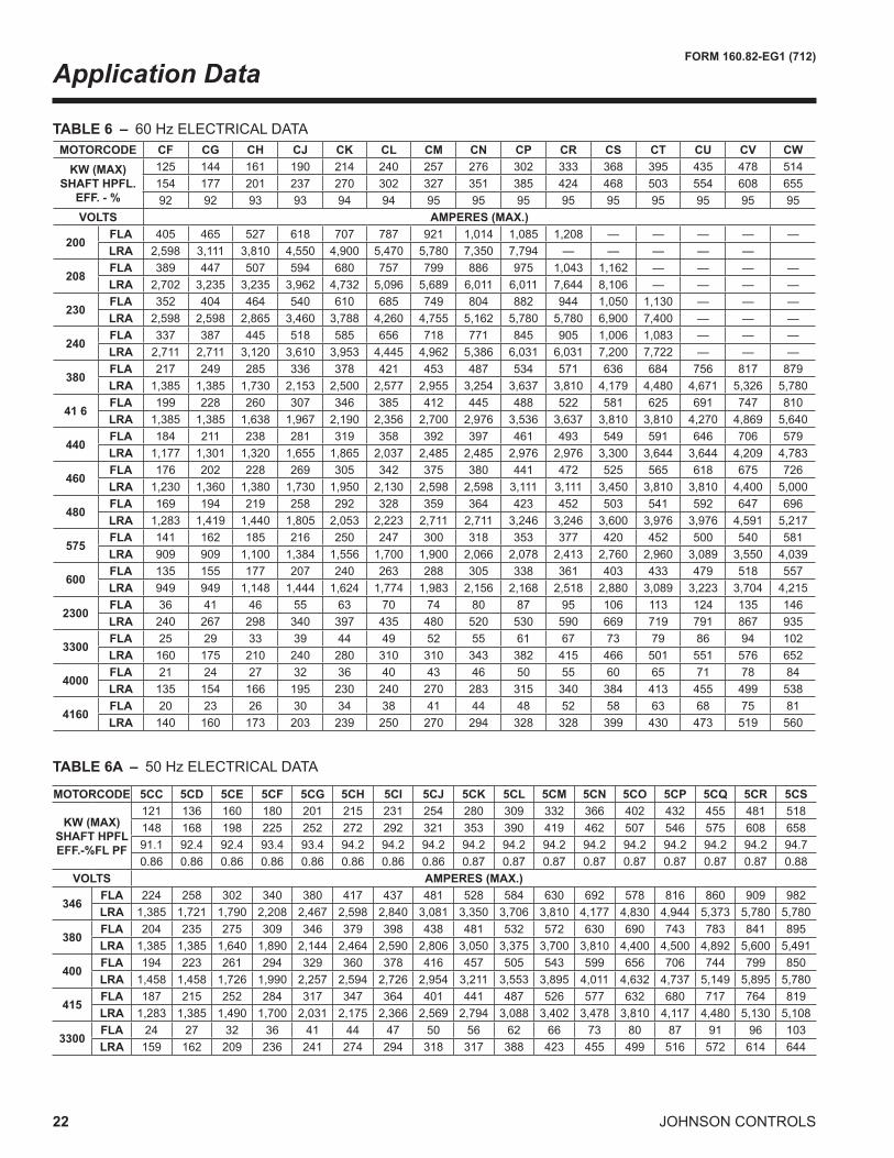
The smallest motor available which equals or exceeds the Inputpower(KW)fromtheunitratingprogramisselectedfromTables5and6.Thefullloadamperes(FLA)listed
in the tables are maximum values and correspond to the maximummotorKWlisted.Whentheinputpower(kW)islessthanmaximummotorKW,theFLAshouldbereducedper the following equation:
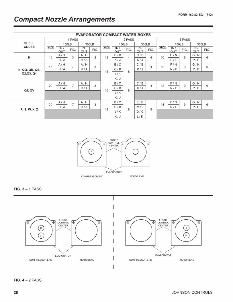
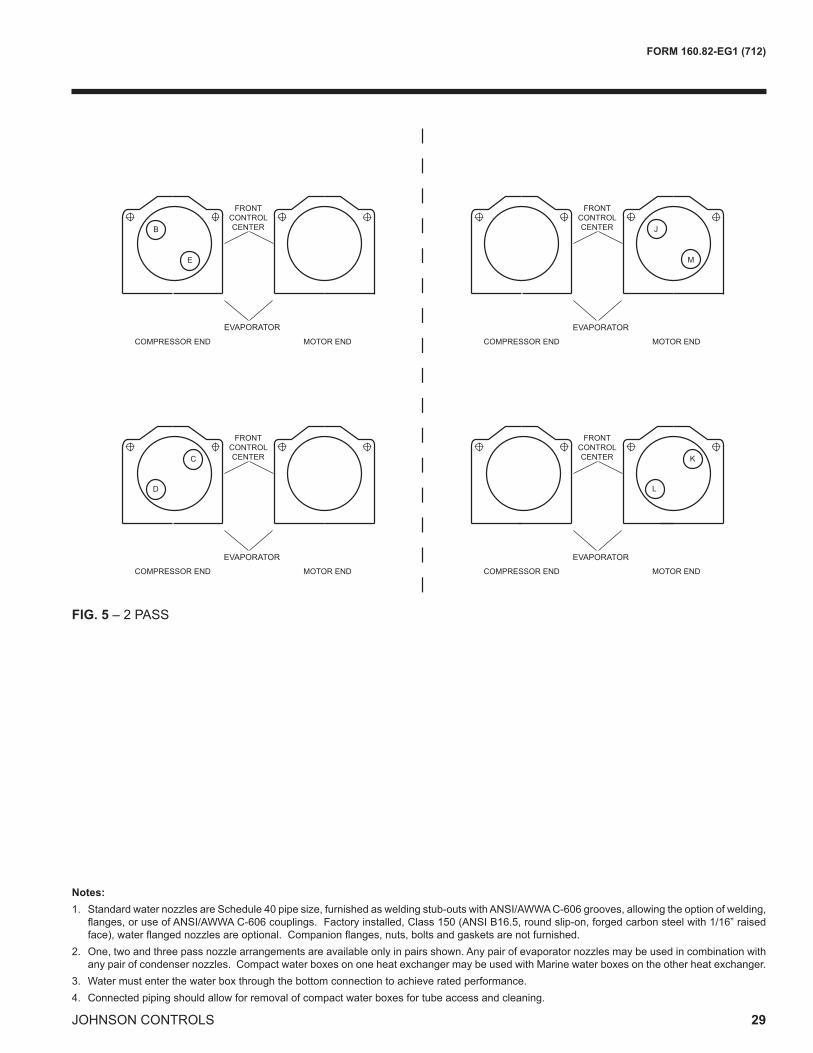
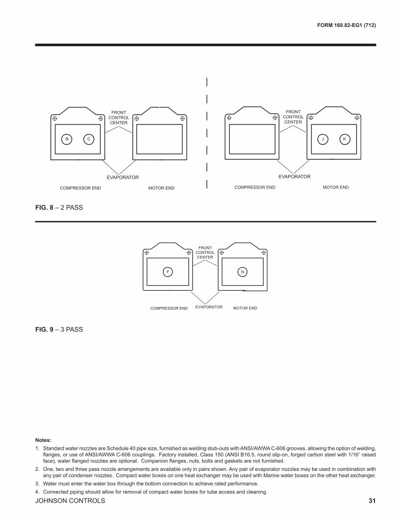
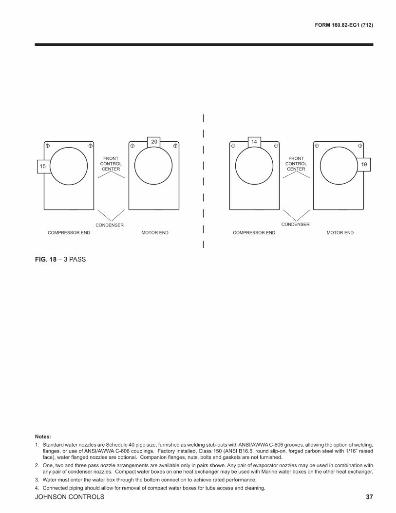
2. One, two and three pass nozzle arrangements are available only in pairs shown. Any pair of evaporator nozzles may be used in combination with anypairofcondensernozzles.CompactwaterboxesononeheatexchangermaybeusedwithMarinewaterboxesontheotherheatexchanger.
3.Watermustenterthewaterboxthroughthebottomconnectiontoachieveratedperformance.4. Connected piping should allow for removal of compact water boxes for tube access and cleaning.
30 JOHNSON CONTROLS
FORM 160.82-EG1 (712)
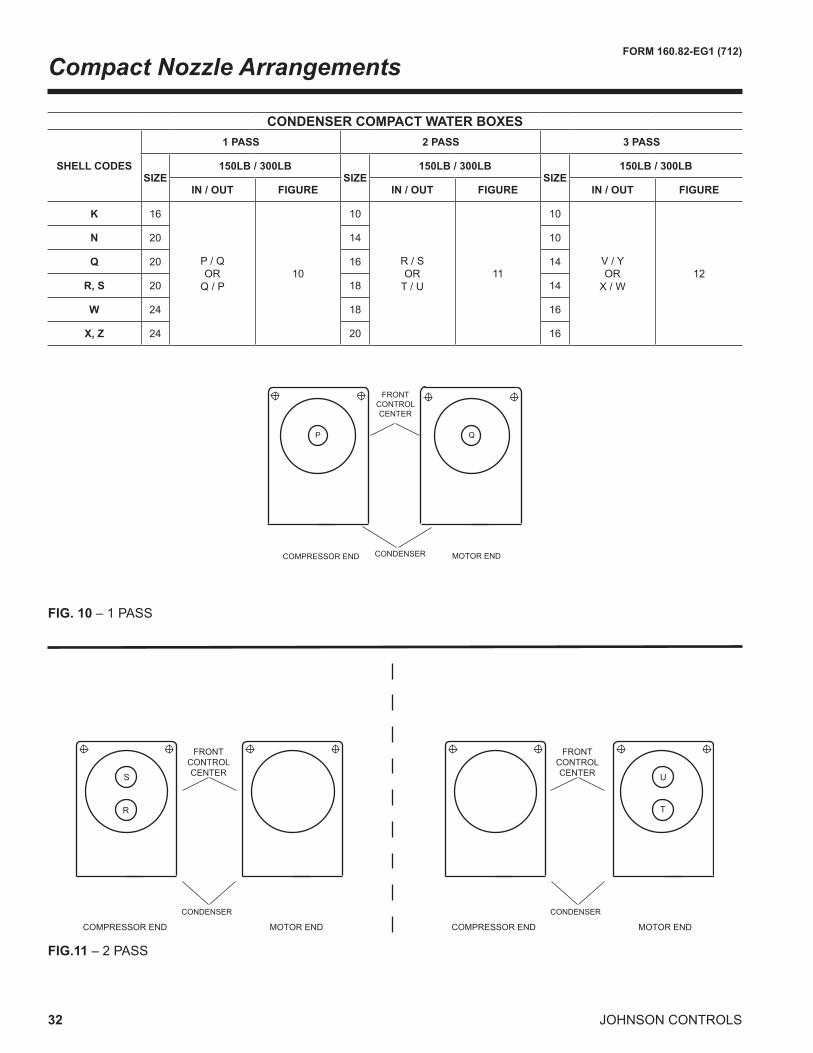
Compact Nozzle Arrangements
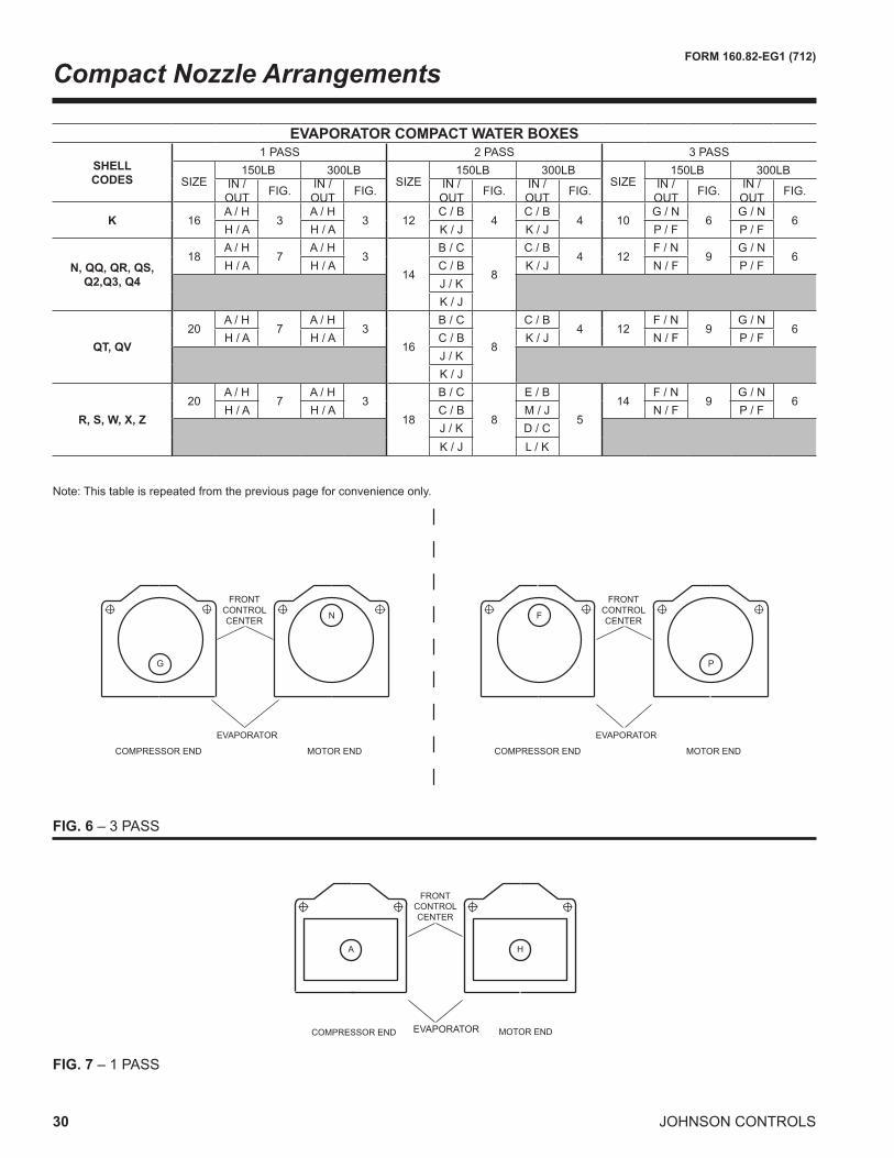
COMPRESSOR END MOTOR END
EVAPORATOR
N
G
FRONTCONTROLCENTER
COMPRESSOR END MOTOR END
EVAPORATOR
F
P
FRONTCONTROLCENTER
FIG. 6 – 3 PASS
A
COMPRESSOR END
FRONTCONTROLCENTER
EVAPORATOR MOTOR END
H
FIG. 7 – 1 PASS
Note: This table is repeated from the previous page for convenience only.
2. One, two and three pass nozzle arrangements are available only in pairs shown. Any pair of evaporator nozzles may be used in combination with anypairofcondensernozzles.CompactwaterboxesononeheatexchangermaybeusedwithMarinewaterboxesontheotherheatexchanger.
3.Watermustenterthewaterboxthroughthebottomconnectiontoachieveratedperformance.4. Connected piping should allow for removal of compact water boxes for tube access and cleaning.
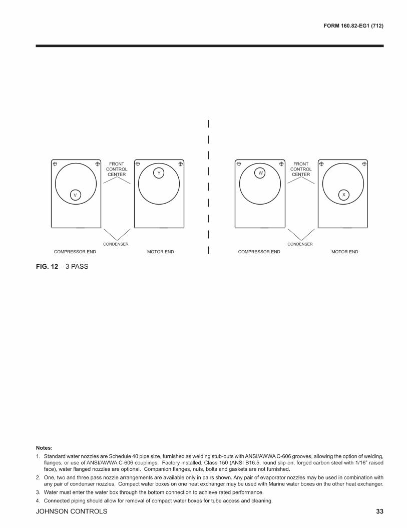
34 JOHNSON CONTROLS
FORM 160.82-EG1 (712)
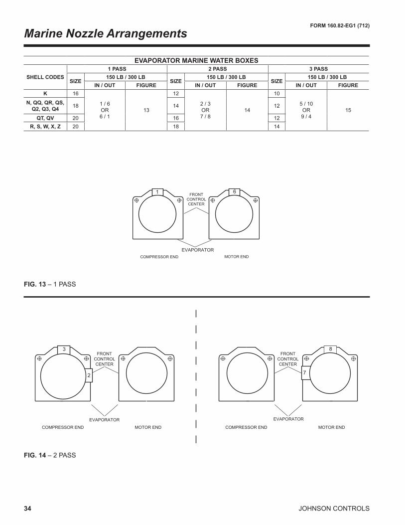
Marine Nozzle Arrangements
EVAPORATOR MARINE WATER BOXES
SHELL CODES1 PASS 2 PASS 3 PASS
SIZE150 LB / 300 LB
SIZE150 LB / 300 LB
SIZE150 LB / 300 LB
IN / OUT FIGURE IN / OUT FIGURE IN / OUT FIGUREK 16
2. One, two and three pass nozzle arrangements are available only in pairs shown. Any pair of evaporator nozzles may be used in combination with anypairofcondensernozzles.CompactwaterboxesononeheatexchangermaybeusedwithMarinewaterboxesontheotherheatexchanger.
3.Watermustenterthewaterboxthroughthebottomconnectiontoachieveratedperformance.4. Connected piping should allow for removal of compact water boxes for tube access and cleaning.
36 JOHNSON CONTROLS
FORM 160.82-EG1 (712)
��������������
������������������
��������� ���������
�� ��
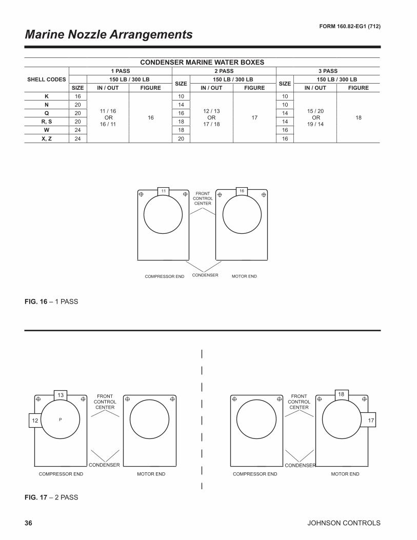
FIG. 16 – 1 PASS
CONDENSER MARINE WATER BOXES
SHELL CODES1 PASS 2 PASS 3 PASS
150 LB / 300 LBSIZE
150 LB / 300 LBSIZE
150 LB / 300 LBSIZE IN / OUT FIGURE IN / OUT FIGURE IN / OUT FIGURE
2. One, two and three pass nozzle arrangements are available only in pairs shown. Any pair of evaporator nozzles may be used in combination with anypairofcondensernozzles.CompactwaterboxesononeheatexchangermaybeusedwithMarinewaterboxesontheotherheatexchanger.
3.Watermustenterthewaterboxthroughthebottomconnectiontoachieveratedperformance.4. Connected piping should allow for removal of compact water boxes for tube access and cleaning.
38 JOHNSON CONTROLS
FORM 160.82-EG1 (712)
GENERAL
Furnishandinstallwhereindicatedonthedrawings____YORK model CYK Compound Centrifugal Compressor LiquidChillingUnit(s).Eachunitshallproduceacapacityof____tons,cooling____GPMof____from____°Fto____°Fwhensuppliedwith____GPMofcondenserwater at ____ °F.Total power input (twomotors) shallnotexceed____kW.Theevaporatorshallbeselectedfor____ fouling factor and amaximum liquid pressuredropof____ft.Watersideshallbedesignedfor150psigworkingpressure.Thecondensershallbeselected for____foulingfactorandmaximumliquidpressuredropof____ft.Watersideshallbedesignedfor150psigworkingpressure. Power shall be supplied to the compressor drive motorsat____volts–3-phase–(60)(50)Hertz.Auxiliarypower to the oil pump motors and controls shall be sup-pliedat___volts–3-phase–(60)(50)Hertz
(or)
Furnish and install where indicated on the drawings___YORKmodelCYK Compound Centrifugal Compres-sorHeatPumpUnit(s).Eachunitshallproduceacapacityof____tons,heating____GMPof____from____°Fto____°Fwhensuppliedwith____GPMofevaporatorwater at ____°F.Total power input (twomotors) shallnotexceed____kW.Theevaporatorshallbeselectedfor____ft.foulingfactorandmaximumliquidpressuredropof____ft.Watersideshallbedesignedfor150psigworkingpressure.Thecondensershallbeselected for____ft.foulingfactorandmaximumliquidpressuredropof____kPa.Watersideshallbedesignedfor150psigworkingpressure.
(or)
Furnish and install where indicated on the drawings___YORKmodelCYK Compound Centrifugal Compressor LiquidChillingUnit(s).Eachunitshallproduceacapac-ityof____kW,cooling____L/Sof____from____°Cto____°Cwhensuppliedwith____L/Sofcondenserwaterat____°C.Totalpowerinput(twomotors)shallnotexceed____kW.Theevaporatorshallbeselected for____m2°C/Wfoulingfactorandmaximumliquidpressuredropof____barg.Watersideshallbedesignedfor10.3bargworkingpressure.Thecondensershallbeselectedfor____m2°C/Wfoulingfactorandmaximumliquidpres-suredropof____barg.Watersideshallbedesignedfor10.3bargworkingpressure.
Power shall be supplied to the compressor drive motors at____volts–3-phase–(60)(50)Hertz.Auxiliarypowerto the oil pump motors and controls shall be supplied at ___volts-3-phase–(60)(50)Hertz.
(or)
Furnish and install where indicated on the drawings___YORKmodelCYK Compound Centrifugal Compres-sorHeatPumpUnit(s).Eachunitshallproduceacapac-ityof____kW,heating____L/Sof____from____°Cto____°Cwhensuppliedwith____L/Sofevaporatorwaterat____°C.Totalpowerinput(twomotors)shallnotexceed____kW.Theevaporatorshallbeselected for____m2°C/Wfoulingfactorandmaximumliquidpressuredropof____kPa.Watersideshallbedesignedfor10.3bargworkingpressure.Thecondensershallbeselectedfor____m2°C/Wfoulingfactorandmaximumliquidpres-suredropof____kPa.Watersideshallbedesignedfor10.3bargworkingpressure.
Eachunitshallbecompletelyfactory-packagedincludingevaporator, condenser, sub-cooler, compressors, flasheconomizer (intercooler), open motors, lubrication system, Control Center, and all interconnecting unit piping and wiring.Theeconomizerisremovedforshipment.Flangedjointsareprovidedandallpipingisprefabricated.Theunitshall be painted prior to shipment. The initial charge of oil and refrigerant shall be supplied, shipped in containers andcylindersforfieldinstallationorfactorychargedintheunit when possible.
COMPRESSORS
Two centrifugal compressors shall be provided, operating in series and using a common refrigerant circuit on the unit.Checkvalveswillbesuppliedonthedischargeofthe low and high stage compressors to control refrigerant flowduringsinglecompressorlowheadoperationandtwocompressor high head operation.
Each compressor shall be a single-stage centrifugal type, powered by an open-drive electric motor. The housing shallbefullyaccessiblewithverticalcircularjoints,withthe complete operating assembly removable from the compressor and scroll housing. Compressor castings on the low stage shall be designed for a minimum 235 psig (16.2 barg)workingpressure andhydrostatically pres-sure tested at a minimum of 352 psig (24.3 barg). The highstageshallbedesignedfor235or350psig(16.2or 24.1 barg) as applicable, and hydrostatically pressure tested at a minimum of 1.3 times the design pressure. The rotor assembly shall consist of a heat-treated alloy steel drive shaft and impeller shaft with a cast aluminum, fully shrouded impeller. The impeller shall be designed for balanced thrust, dynamically balanced and over-speed tested for smooth, vibration-free operation. Insert-type journalandthrustbearingsshallbefabricatedofaluminumalloy, precision bored and axially grooved.
Guide Specifications
FORM 160.82-EG1 (712)
39JOHNSON CONTROLS
Internal single helical gears with crowned teeth shall be designed so that more than one tooth is in contact at all times to provide even load distribution and quiet operation. Eachgearshallbeindividuallymountedinitsownjournaland thrust bearings to isolate it from impeller and motor forces. Shaft seal shall be provided in double bellows, double-seal, cartridge type. A gravity-fed oil reservoir shall be built into the top of the compressor to provide lubrica-tion during coast-down in the event of a power failure.
Capacity control shall be achieved by use of pre-rotation vanes to provide fully modulating control from full load to minimum load. Control shall automatically compensate for adverse operating conditions, such as fouled tubes, and adjusttoprioroperationaftercorrectionofthesecondi-tions. The unit shall be capable of continuous, reliable operationwithlowECWTatallloadconditionsasoutlinedon the equipment schedule. An external electric actuator shall automatically control pre-rotation vane position for each compressor.
LUBRICATION SYSTEM
Lubricationoilshallbeforce-fedtoallcompressorbear-ings, gears, and rotating surfaces by variable speed oil pumps mounted in individual oil reservoirs. Each oil pump shallvaryoilflowtoitscompressorbasedonoperatingand stand-by conditions, ensuring adequate lubrication at all times. The oil pump shall operate prior to start-up, during compressor operation and during coast-down.
Dualoilreservoirs,separatefromthecompressors,shallcontainthe2HPsubmersibleoilpumpsand1500wattimmersion-type oil heaters for each compressor. The oil heaters shall be thermostatically controlled to remove re-frigerant from the oil. The oil reservoirs shall be designed andstampedinaccordancewithASMEpressurevesselcode. A non-code reservoir is not acceptable.
Water-cooledoilcoolersshallbeprovidedaftereachoilpump, with factory installed water piping. A thermostati-cally controlled bypass valve shall maintain the required oil temperature supply from each oil cooler to its compressor.
Oilshallbefilteredbyexternallymounted,1/2micron,re-placeablecartridgeoilfilters,equippedwithservicevalves.An automatic oil return system to recover any oil that may have migrated to the evaporator shall be provided. Oil piping shall be completely factory installed and tested.
MOTOR DRIVELINE
Each compressor motor shall be an open drip-proof, squir-relcage,inductiontypeoperatingat3570rpm(2975rpmfor50Hzoperation).
EachopenmotorshallbeprovidedwithaD-flange,boltedto a cast iron adaptor mounted on the compressor to al-low the motor to be rigidly coupled to the compressor to provide factory alignment of motor and compressor shafts.Each motor drive shaft shall be directly connected to its compressorshaftwithaflexibledisccoupling.Thecou-pling shall have all metal construction with no wearing parts to assure long life, and no lubrication requirements to provide low maintenance. A large steel terminal box withgasketed frontaccesscovershallbeprovided forfield-connectedconduit.
EVAPORATOR
Evaporatorshallbeof theshell-and-tube,flooded typedesignedforaminimumof180psig(12.4barg)workingpressure on the refrigerant side. Shell shall be fabricated from rolled carbon steel plates with fusion welded seams, carbon steel tube sheets, drilled and reamed to accom-modate the tubes, and intermediate tube supports spaced no more than four feet apart. The refrigerant side of each shell is designed, tested and stamped in accordance withASMEBoiler andPressureVesselCode,SectionVIII–DivisionI.
Heatexchangertubesshallbehigh-efficiency,externallyandinternallyenhancedtype.Tubesshallutilizethe“skip-fin” design, providing a smooth internal and externalsurface at each intermediate tube support. This provides extrawallthicknessandnon-workhardenedcopperatthesupport location, extending the life of the heat exchangers. Ifskip-fintubesarenotused,minimumtubewallthick-nessshallbe0.035”(0.889mm).Eachtubeshallberollerexpandedintothetubesheetsprovidingaleak-proofseal,andbe individually replaceable.Watervelocity throughthetubesshallnotexceed12ft./sec.(3.65m/sec).Aliq-uid level sight glass shall be provided on the side of the shell to aid in determining proper refrigerant charge and tocheckconditionof the refrigerantcharge.Aluminummesheliminatorsorbafflesshallbe locatedabove thetube bundle to prevent liquid refrigerant carryover to the compressor. The evaporator shall have a refrigerant relief devicesizedtomeettherequirementsoftheASHRAE15SafetyCodeforMechanicalRefrigeration.
Waterboxesshallberemovabletopermittubecleaningand replacement. Stub-out water connections having ANSI/AWWAC-606grooves shall be provided.Waterboxesshallbedesignedfor150psig(10.3barg)designworkingpressureandbetestedat225psig(15.5barg).Vent and drain connections with plugs shall be provided on eachwaterbox.Lowflowprotectionshallbeprovidedbyathermal-typeflowsensor,factorymountedinthewaternozzle connection and wired to the unit panel.
40 JOHNSON CONTROLS
FORM 160.82-EG1 (712)
CONDENSER
Condenser shall be of the shell-and-tube type, designed foraminimumof235psig(16.2barg)workingpressureon the refrigerant side. Shell shall be fabricated from rolled carbon steel plates with fusion welded seams. Carbon steel tube sheets, drilled and reamed to accommodate the tubes, are welded to the end of each shell. Intermediate tube supports are drilled and reamed to eliminate sharp edges, fabricated from carbon steel plates. The refriger-ant side of each shell is designed, tested and stamped in accordancewithASMEBoilerandPressureVesselCode,SectionVIII–DivisionI.
Heat exchanger tubes shall be high efficiency, exter-nally and internally enhanced type. Tubes shall utilize the “skip-fin” design, providing a smooth internal andexternal surface at each intermediate tube support. This provides extrawall thickness and non-work hardenedcopper at the support location, extending the life of the heatexchangers.Ifskip-fintubesarenotused,minimumtubewallthicknessshallbe0.035”(0.889mm).Eachtubeshall be roller expanded into the tube sheets providing a leak-proof seal, andbe individually replaceable.Watervelocitythroughthetubesshallnotexceed12ft./sec.(3.65m/sec.).Aliquidlevelsightglassshallbeprovidedontheside of the shell to aid in determining proper refrigerant chargeandtocheckconditionoftherefrigerantcharge.The condenser shall have dual refrigerant relief devices; eachsizedtomeettherequirementsoftheASHRAE15SafetyCodeforMechanicalRefrigeration.Arrangementshall allow either valve to be isolated and replaced without removing the unit refrigerant charge.
Waterboxesshallberemovabletopermittubecleaningand replacement. Stub-out water connections having ANSI/AWWAC-606grooves shall be provided.Waterboxesshallbedesignedfor150psig(1034barg)designworkingpressureandbetestedat225psig(1551barg).Vent and drain connections with plugs shall be provided oneachwaterbox.Athermal-typewaterflowsensorshallprovidelowflowprotection,factorymountedinthewaternozzle connection and wired to the unit control panel.
FLASH ECONOMIZER (INTERCOOLER)
A single stage flash economizer (intercooler) shall beprovided with internally mounted mesh eliminators, liquid spraypipe,anexternallymounted(field installed) leveltransmitter and an external control valve. Economizer shall include eight sight glasses, two above and two below the mesh eliminators, two at the liquid spray pipe and two in liquid line leaving the economizer. A thermometer well shallbefurnishedforcheckingliquidtemperature.Con-nectionsandfieldinstalledpressuretransmitterandreliefvalveassembliesshallbeprovidedforfieldinstallation.
Support legs of structural steel tubing shall be provided withmountingbracketsforoptionalspringtypeisolators.
CONTROL CENTER
General – The unit is controlled by a stand-alone Quan-tumLXmicroprocessorbasedcontrolcenterwithLinuxoperating system (a PLC control center is providedforDualEvaporatorCYK). The unit control panel shall provide control of unit operation and monitoring of unit sensors, actuators, relays and switches. The unit panel shall provide capacity control operation of the two series compressors in reponse to low entering condenser water and start-up requirements. The panel shall also allow the unittooperatedownto0%evaporatorload.
Control Panel – Thecontrolpanelshallincludea10.4”coloractivematrixdisplaywithintegralkeypadandtouch-screen for operator interface. The control panel shall be factorywired,unitmounted,Nema12,gasketedenclo-sure.Thepanelshallbefabricatedof10gaugesteelandinclude full height front access door. The panel enclosure shall be painted to match the unit color. All controls are arranged for easy access and internally wired to clearly marked terminalstripswiringconnections.Wiringshallbecolor-codedblack(power),red(control),light-blueandgreen(ground),witheachwirenumericallyidentifiedatbothendswithwiremarkers.Wiringenclosedinshieldedcables and pre-wired cables shall be color coded per the wiring diagram.
The screen shall detail all operations and parameters, using a graphical representation of the unit and its com-ponents.Graphicscreensshallprovidefor:
a. Unit Overviewb. Evaporatorc. Condenserd. Lowstagecompressore. Highstagecompressorf. Motorsg. Capacity control diagramh. Manual/Autostationsforallcontroloutputs
The operator interface shall be programmed to provide displayofallmajoroperatingparametersinbothgraphicalandlisttypescreendisplays.PIDcontrolloopsetpoints,andManual/Autofunctionsshallbeaccomplishedbytheoperator interface. Alarm indicators on the graphic display screen shall provide annunciation, and an alarm history screen to which show the most recent alarms, with the time and date of occurrence. Trip status screens shall be provided which show the values of all analog inputs at thetimeofthelast128unitsafetyshutdowns.Thetime
Guide Specifications
FORM 160.82-EG1 (712)
41JOHNSON CONTROLS
anddateoftheshutdownshouldalsobeshown.FunctionKeys shall be provided on the control panel for Unit Start, Stop, Reset and Emergency Stop.
TheQuantumLXcontrolsystemcanbeaccessedremotelyby any internet browser, when it is incorporated into an eth-ernetnetwork.Thisvirtualoperatorinterfaceallowsquickaccess to the units for full remote management without havingtocreateaseparateSCADAorsupervisorycontrol.
CAPACITY CONTROLS SYSTEM
The Capacity Control philosophy of the unit control system shallallowefficient fullyautomatedcontrol,withoutneedfor operator intervention. This control system shall monitor and display all safety aspects of the unit and provide alarms and a shutdown if safety limits are exceeded. If operator intervention is required, manual controls shall be provided on the electronic operator interface, for all electric actuators.
Thecapacity controlsalgorithmshallautomatically seekoutthemostefficientoperationoftheunit.Thepre-rotationvanes are automated to obey the temperature controller to maintain chilled water production. In cases of low load, the pre-rotation vanes shall automatically throttle and be limited to a minimum anti-surge position. To provide light duty opera-tion, the hot gas recycle valve shall be seamlessly throttled openaccordingtotemperaturedemands.Thiskeepsthecentrifugal compressor out of surge and maintains chilled water production.
Incasesofhigh load,whichexceeds themotorkilowatt(or current) usage, the capacity controls algorithm shall automatically unload the system to maintain a restriction on power consumption. In the same way, conditions of high discharge pressure or low suction pressure shall override theproductionofchilledwaterintheinterestsofkeepingtheunit system online.
In cases of light load and low head, the high stage compres-sorshallbedroppedoffline,theflasheconomizerbypassed,andtheunitwillberunwiththelowstagecompressorlikeanormal single-compressor unit.
Temperature 18.HighStageCompressorRefrigerantDischarge
Temperature 19.SubcooledRefrigerantLiquidTemperature20.LowStageCompressorOilTemperature21.HighStageCompressorOilTemperature22.LowStagePRVPosition 23.HighStagePRVPosition24.LowStageCompressorhighstagethrustBearing
Security access to prevent unauthorized change of set-points, to allow local or remote control of the unit, and to allow manual operation of the pre-rotation vanes and oilpumpshallbeprovided.AccessshallbethroughIDandpasswordrecognition,whichisdefinedbythreedif-ferent levels of user experience: operator, service and programming.
OVER-CURRENT PROTECTION
The Variable Speed Oil Pump Panel shall include a fused connection through a transformer to provide individual over-current protected power for all controls.
PLANT MANAGEMENT/CONTROL SYSTEM INTER-FACE:
Ethernet is the preferred LAN (LocalAreaNetwork)betweenLocalUnitControlPanels.Ethernetallowsfullmanagementof theQuantumLXsystemfromacentrallocation.
TheQuantumLXcontrolsystemcanbeaccessedremotelyby any internet browser, when it is incorporated into an eth-ernetnetwork.Thisvirtualoperatorinterfaceallowsquickaccess to the units for full remote management without havingtocreateaseparateSCADAorsupervisorycontrol.
All required analog and discrete data for communica-tionswillbearrangedinblocksof16-bitwords.Alldatais available remotely as read only values. The following write-able control signals are available. Remote Start, RemoteStop,RemoteLeavingChilledWaterSetpoint,andRemoteDemandLimitSetpoint.
Available Network ProtocolsAnyprotocol/mediarequirementsnotlistedbelowmustbe called out on the factory order form.
Available protocols will be implemented with a Johnson Controls eLink module* or RedLion Data Station where applicable:• ModbusRTUoverRS-485**• BACnetMS/TP*• BACnet/IP*
Check appropriate protocol and include this docu-ment attached to the Factory Order Form.
All communication interface wiring and hardware, which is required external to the unit control panel, will be supplied and installed by the electrical installation contractor under another contract.
FACTORY-SUPPLIED COMPRESSOR MOTOR START-ER (2300V & 4160V/3/60Hz or 3300V/3/50Hz)
The unit manufacturer shall furnish a reduced-voltage, MediumVoltageSolid-State Starter, in accordance with theunitmanufacturer’sstarterspecifications.Thestartershall be of modular construction with complete access to all parts. The starter shall be tested and the design starting current and overload settings adjusted at thefactory. The starter shall provide, through the use of six in-line(notinsidetheDelta)siliconcontrolledrectifiers(2per phase), a smooth acceleration of the motor without current transitions or transients.
The following protective devices and convenience items shall be factory mounted and wired to the starter:a. 3-leg Sensing Electronic Overloads – shuts unit
b. Phase Rotation Protection Circuit – denies start-up when detecting incorrect power wiring phase sequence to the starter which could cause reverse motor rotation and damage the equipment.
c. Single-Phase Failure Protection Circuit – ensures against motor burnout by shutting the unit down if power loss occurs in any of the incoming lines during start-up.
d. High Temperature Safety Protection System –temperatureactivatedswitchesonheatsinkswillshut the unit down if the SCR temperature exceeds acceptable limits.
e. 3-Phase Digital Ammeter And Digital Voltmeter Readout Via Control Center–easilycross-checkdesign current and voltage limitations against supply characteristics.
f. Startermounted loadbreak rated inputdisconnectswitchwithinterlockedpadlockablehandle.Positivedisconnecting means shall be visible from outside
the enclosure, in operator area. All doors shall be interlockedwiththedisconnectingmeans.
g. Open/Shorted SCR Protection – Failed semi-conductor devices are automatically detected and reported via the Control Center.
h. Power Fault Protection – momentary power inter-rup-tion protection detects power interruptions within 3 line cycles and interrupts power to the compressor motor within 1 additional line cycle.
i. Electrical Connections – these tin-plated or copper bus bars provide easy connection to incoming copper power lines.
k. Wattmeter – An instantaneous wattmeter tells the customer how much power the unit is consuming. A kilowatt-hourenergymeterisalsoprovidedtomea-sure power consumption over a period of time.
l. Shutdown History –TheMediumVoltageSolid-State Starter shall provide the system control panel with ten histories of previous unit shutdowns initiated by the starter.
In addition, the Starter shall include as standard, the fol-lowing convenience items already mounted and wired to the starter at the factory: • Auxiliarycontrolsupplytransformer–eliminatesthe
needforrunningseparate115V-1Ø-50/60Hzpowersource wiring to the unit Control Center.
REMOTE ELECTRO MECHANICAL COMPRESSOR MOTOR STARTER (OPTION)
A remote electro mechanical starter of the R-1132 type shall be furnished for each compressor motor. The starter shall be furnished in accordance with the unit manufac-turer’sstarterspecificationsandasspecifiedelsewhereinthesespecifications.
PORTABLE REFRIGERANT STORAGE/RECYCLING SYSTEM
Aportable, self-contained refrigerant storage/recyclingsystem shall be provided consisting of a refrigerant com-pressor with oil separator, storage receiver, water-cooled condenser,filterdrierandnecessaryvalvesandhosesto remove, replace and distill refrigerant. All necessary controls and safety devices shall be a permanent part of the system.
SI Metric Conversion
Values provided in this manual are in the English inch-pound (I-P) system. ThefollowingfactorscanbeusedtoconvertfromEnglishtothemostcommonSlMetricvalues.